i ns tr uc ti on m a nua l zwd2 2 5 paf se r i es i ns t ... tdk-lambda zw d225pa f s er i es i ns...
TRANSCRIPT
PA574-04-01F
TDK-Lambda ZWD225PAF Series INSTRUCTION MANUAL
ZWD225PAF Series Instruction Manual
BEFORE USING THE POWER SUPPLY UNIT
Pay attention to all warnings and cautions before using the unit. Incorrect usage could lead to an elec-trical shock, damage to the unit or a fire hazard.
WARNING and CAUTION
· Do not modify.
· Do not touch the internal components, they may have high voltage or high temperature. You may get electrical shock or burned.
· When the unit is operating, keep your hands and face away from it, you may get injured by an accident.
· This power supply is primarily designed and manufactured to be used and enclosed in other equipment. Stick the WARNING label for users on the system equipment and describe the notice in the instruction manual.
· Never operate the unit under over current or shorted conditions for 30 seconds or more and outside of its specified Input Voltage Range which could result in damage.There is no possibility of fire or burning.
· Confirm that connections to input/output terminals are correct as indicated in the instruction manual.
· This power supply is PC board type unit. Please hold the board edge while mounting, and do not touch the component side. Please lift the power supply with a spacer when mounting the power supply on any sur-face.
· This power supply is capable of providing hazardous energy output(240VA), the end equipment manu-facturer must provide protection to service personal against inadvertent contact with output terminals. This terminal must not be user accessible.
· Under single fault conditions in secondary circuits, the output(s) of this product may go non-SELV be-tween parts of the secondary circuits and earth. It is therefore necessary to earth the output(s) to maintain SELV between output(s) and earth. Alternatively, the output(s) may be considered hazardous and must not be made user accessible in the end equipment.
· Do not drop or apply shock to power supply unit. Note: CE MARKING
CE Marking, when applied to a product covered by this handbook, indicates compliance with the low voltage directive.

- 1 -
TDK-Lambda ZWD225PAF Series INSTRUCTION MANUAL
1. Terminal Explanation
1-1. ZWD225PAF
L: AC Input terminal (pin 6 of CN1) Live line (fuse in line)
N: AC input terminal (pin 4 of CN1) Neutral line
FG: Input terminal FG (pin 1 of CN1) Safety earth (Frame Ground)
Connect to safety ground of apparatus or equipment.
PE: Protective Earth (Connected to pin 1 of CN1)
Must be connected to electrically safety ground of apparatus or equipment by electrically conductive spacers. The mounting surface of the spacer should be within MAX f8mm.
V1: CH1 +ve Output terminal G1: CH1 –ve Output terminal V2: CH2 +ve Output terminal G2: CH2 –ve Output terminal V.ADJ: 5V Output Voltage adjust trimmer (VR1)
The 5V Output voltage rises when the trimmer is turned clockwise.
V.ADJ : 24V Output Voltage adjust trimmer (VR2) The 24V Output voltage rises when the trimmer is turned clockwise.
-R : CN3 ON/OFF control -R terminal +R : CN3 ON/OFF control +R terminal
*Input & Output connector (MOLEX) (also for option model /L,/A)
Recommended Connector Housing Terminal Pin
Input (CN1)
5414-30B or 5273-06A(1.4.6)
5195-06 or 2139-06 or 3069-06
5194PBTL
Output (CN2) 5273-10A
5195-10 or 2139-10 or 3069-10
5194PBTL
*Output Current of each connector pin must be less than 5A.(7A at peak load)
*Hand Crimping Tooling : 11-26-0058 (MOLEX) *Connector for Remote ON/OFF control: CN3 (JST)
*CN3 is normally shorted by JM-2W-96 ( JST ) *Hand Crimping Tool: YC-110R (JST) or YRS-110 (JST)
Recommended
Connector Housing Terminal Pin
B2B - XH - A XHP – 2 BXH - 001T - P0.6
or SXH - 001T - P0.6

- 2 -
TDK-Lambda ZWD225PAF Series INSTRUCTION MANUAL
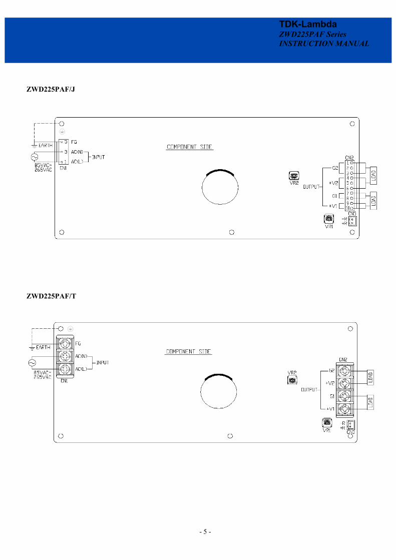
1-2. ZWD225PAF/J
L: AC Input terminal (pin 1 of CN1) Live line (fuse in line)
N: AC input terminal (pin 3 of CN1) Neutral line
FG: Input terminal FG (pin 5 of CN1) Safety earth (Frame Ground)
Connect to safety ground of apparatus or equipment. PE: Protective Earth (Connected to pin 5 of CN1)
Must be connected to electrically safety ground of apparatus or equipment by electrically conductive spacers. The mounting surface of the spacer should be within MAX f8mm.
V1: CH1 +ve Output terminal G1: CH1 –ve Output terminal V2: CH2 +ve Output terminal G2: CH2 –ve Output terminal V.ADJ: 5V Output Voltage adjust trimmer (VR1)
The 5V Output voltage rises when the trimmer is turned clockwise.
V.ADJ : 24V Output Voltage adjust trimmer (VR2) The 24V Output voltage rises when the trimmer is turned clockwise.
-R : CN3 ON/OFF control -R terminal +R : CN3 ON/OFF control +R terminal
*Input & Output connector ( JST ) (also for option model /JL,/JA)
Recommended Connector Housing Terminal Pin
Input (CN1) B3P5-VH VHR-5N SVH-21T-P1.1 Output (CN2) B10P-VH VHR-10N SVH-21T-P1.1
*Output Current of each connector pin must be less than 5A. (7A at peak load) *Hand Crimping Tool : YC-160R ( JST ) *Connector for Remote ON/OFF control: CN3 (JST)
Recommended
Connector Housing Terminal Pin
B2B - XH - A XHP - 2 BXH - 001T - P0.6
or SXH – 001T - P0.6
*CN3 is normally shorted by JM-2W-96 ( JST ) *Hand Crimping Tool: YC-110R (JST) or YRS-110 (JST)

- 3 -
TDK-Lambda ZWD225PAF Series INSTRUCTION MANUAL
1-3. ZWD225PAF/T
L: AC Input terminal L (M4 screw) Live line (fuse in line) N: AC input terminal N (M4 screw) Neutral line FG: Input terminal FG (M4 screw)
Safety earth (Frame Ground) Connect to safety ground of apparatus or equipment.
PE: Protective Earth Must be connected to electrically safety ground of apparatus or equipment by electrically conductive spacers. The mounting surface of the spacer should be within MAX f8mm.
V1: CH1 +ve Output terminal G1: CH1 –ve Output terminal V2: CH2 +ve Output terminal G2: CH2 –ve Output terminal V.ADJ: 5V Output Voltage adjust trimmer (VR1)
The 5V Output voltage rises when the trimmer is turned clockwise.
V.ADJ : 24V Output Voltage adjust trimmer (VR2) The 24V Output voltage rises when the trimmer is turned clockwise.
-R : CN3 ON/OFF control -R terminal +R : CN3 ON/OFF control +R terminal
* Input & Output connector ( EMUDEN ) (also for option model /TL,/TA)
*Connector for Remote ON/OFF control: CN3 (J.S.T) Recommended
Connector Housing Terminal Pin
B2B – XH - A XHP – 2 BXH - 001T - P0.6
or SXH - 001T - P0.6
*CN3 is normally shorted by JM-2W-96 ( J.S.T ) *Hand Crimping Tool: YC-110R (J.S.T) or YRS-110 (J.S.T)
Connector Input (CN1) T6957-A-X
Output (CN2) T6958-A-X

- 4 -
TDK-Lambda ZWD225PAF Series INSTRUCTION MANUAL
2. Terminal Connecting Method
Pay attention to the input wiring. If it is connected to the wrong terminal, the power supply will be damaged.
· Input must be turned off when making connections. · Connect FG terminal of input connector and mountable
PE to ground terminal of the equipment. · Output current of each connector pin must be less than
5A. ( Except /T model which M4 screw is used. ) · The output load line and input line shall be separated
and twisted to improve noise sensitivity. · Remote ON/OFF control lines shall be twisted or use
shielded wire. · Use recommended input/output connector housing,
terminal pin & crimping tool. Connector housing and terminal pin is not included with this product.
· When connecting or removing connector, do not apply stress to PCB.
ZWD225PAF
- 5 -
TDK-Lambda ZWD225PAF Series INSTRUCTION MANUAL
ZWD225PAF/J
ZWD225PAF/T

- 6 -
TDK-Lambda ZWD225PAF Series INSTRUCTION MANUAL
3. Explanation of Function and Precautions
3-1. Input Voltage Range Input voltage range is single phase 85 ~ 265VAC ( 47 ~ 63Hz ) or 120 ~ 300VDC. For cases of application under 300 to 370VDC input, please contact to our sales office. Input voltage which is out of specification may damage unit. For cases where conformance to various safety specs(UL,CSA,EN) are required, input voltage range will be 100 ~ 240VAC ( 50/60Hz ). 3-2. Output Voltage Range V.ADJ trimmer (VR1 & VR2) which is nearby to output connector is for output voltage adjustment. Please refer to the specifications for the output adjustment range. When the trimmer is turned clockwise, the output voltage will increase. Note that over voltage protection (OVP) function may trigger if the output voltage is increased excessively. 3-3. Inrush Current This series used Power Thermistor to protect the circuit from Inrush Current. Please carefully select input switch and fuse in cases of high temperature and brown-out. 3-4. Over Voltage Protection ( OVP ) OVP circuit will shutdown output correspondingly. OVP for V1, both V1 & V2 will shutdown, OVP for V2, only V2 shutdown. Manual reset or input voltage recycling is needed for output recovery. 3-5. Over Current Protection ( OCP ) OCP type is constant current limiting with automatic recovery. OCP function operates when the output current exceeds OCP specifications. The output will automatically recover when the overload condition is removed. Do not operate overload or dead short conditions for more than 30 seconds, which could result in damage. There is no possibility of fire or burning. 3-6. Over Temperature Protection ( OTP ) OTP circuit is built into the power supply to prevent user from fire hazard when ambient temperature is over the specification.
3-7. Output Ripple & Noise The standard specification for maximum ripple and noise value is measured according to measurement circuit specified below When load lines are longer, ripple and noise may become larger. In this case, electrolytic capacitor, film capacitor, etc. might be necessary across the load terminal. The output ripple and noise cannot be measured accurately if the oscilloscope probe ground lead is too long.
3-8. Series Operation Series operation is not possible.
Output Terminal
Output Terminal
Power Supply
Load
3-9. Parallel Operation Paralled operation is not possible.
Load
Output Terminal
Output Terminal
Power Supply

- 7 -
TDK-Lambda ZWD225PAF Series INSTRUCTION MANUAL
3-10. Peak Output Current For ZWD225PAF series, the peak output current should satisfy the conditions below: 1)Should not exceed the rated peak current in the specification.
(eg. 14/18A respectively for 100VAC/200VAC) 2)The relation between peak output current with average output
current is defined as below.
Ip = Peak output current Im = Minimum output current D = Duty cycle, t/T t = Peak output current operating time T = Period Io = Maximum allowable average output current of specifica-
tions (Io should be average load after derating at various mounting and ambient temperature)
3)For peak output current (Ip ≤ 14A) at 100VAC & 200VAC,
the duty cycle of the peak output current is ≤ 35% and oper-ating time of the peak output current is less than 10 seconds. For peak output current (Ip ≤ 18A) at 200VAC only, the duty cycle of the peak output current is ≤ 20% and operating time of the peak output current is less than 5 seconds. Maximum ambient has to be reduced by 10°C if 35% duty operation is required.
Vin (VAC) Ip (max) Duty(max) t(sec) 85 ~ 132 14A 35% 10sec 170 ~ 265 14A 35% 10sec 170 ~ 265 18A 20% 5sec
4)Formula:
ZWD225PAF: Io(ave) = Ip x D + Im x (1-D) ≤ Io spec. (refer to derating curve) Example : For ZWD225PAF-0524 at Ta =60°C,Mounting A,
Max Io(ave) =4.5A (after 50% Derating) Io(ave) = Ip x D + Im x (1-D) ≤ Io spec. (A)100VAC : In case of Im =0, Ip =14A,
D<32% (B)200VAC : In case of Im =2A, Ip =18A,
D<15% 3-11. Remote ON/OFF Control Remote ON/OFF control (CN3) function is available. Using this function allows the user to turn the 24V output on and off without having to turn the AC input on and off. It is controlled by short or open between +R & -R of CN3. CN3 is provided in the secondary circuit for ON/OFF control by means of a switch or other device. [CN3] The control mode is shown below.
+R & -R Terminal condition Output condition of V2 Short < 0.5V ON Open > 4.5V OFF
3-12. Isolation Test Isolation resistance between output and PE (Chassis) shall be more than 100MW at 500VDC. For safety operation, voltage setting of DC isolation tester must be done before the test. Ensure that it is fully discharged after the test. Output – PE ( Chassis ) 500VDC 100MW or more
AC(L)
AC(N)
+V1
G1 FG
+V2
G2
Isolation Tester
+R
-R
(ave)
PE

- 8 -
TDK-Lambda ZWD225PAF Series INSTRUCTION MANUAL
3-13. Withstand Voltage This series is designed to withstand 3.0kVAC between input and output, 2.0kVAC between input and PE (Chassis) and 500VAC between output and the PE (Chassis) each for 1 mi-nute. When performing this test, set current limit of the with-stand voltage test equipment to 20mA ( Output - PE (Chassis) : 100mA ). The applied voltage must be gradually increased from zero to the test value and then gradually decreased for shut down. When timer is used, the power supply may be damaged by high impulse voltage during timer switch on and off. Con-nect input and output as follows. Input ~ Output (dotted line )
3kVAC 1min. ( 20mA ) Input ~ PE (Chassis) (solid line ) 2kVAC 1min. ( 20mA )
AC(L)
AC(N)
+V1
G1 FG
+V2
G2
Withstand Voltage Tester
+R
-R
Output ~ PE (Chassis)
500VAC 1min. ( 100mA )
AC(L)
AC(N)
+V2
G2 FG
+V1
G1
Withstand Voltage Tester
+R
- R
3-14. External connection of circuit with protective seperation All the outputs is protected using protection of SELV. ( As per required in the EN50178, clause 5.2.8) 3-15. Max Current during abnormal The Max output current of CH1 under any abnormal situation is 8.1 A (DC) The Max output current of CH2 under any abnormal stituation is 21.2 A (DC) 3-16. Climatic condition This product is certified to the Climatic condition, Type B of the EN50178.
PE
PE

- 9 -
TDK-Lambda ZWD225PAF Series INSTRUCTION MANUAL
4. Mounting Directions
4-1. Output Derating according to the Mounting Direc-tions
Recommended standard mounting method is (A). Method (B), (C), (D), (E) are also possible. Mounting (F), (G), (H), (I) are prohibited. Refer to the derating curve. In the following de-rating curve, average load(%) is percent of maximum output load (both Maximum Output Current and Maximum Output Power in specifications). Do not exceed the load deratings. PCB type ( A )
With chassis and with chassis&cover type mounting method
( A ) Standard Mounting
( B )
( C ) ( D )
( E ) ( F ) Prohibit
( G ) Prohibit
Input
Input
Output
Component
Input
Output
Input
( B )
( C )
Standard Mounting
( D )
Component
Input
Input
Input
Output
Output
Input
( H ) Prohibit
( I ) Prohibit
( E ) ( F ) Prohibit
- 10 -
TDK-Lambda ZWD225PAF Series INSTRUCTION MANUAL
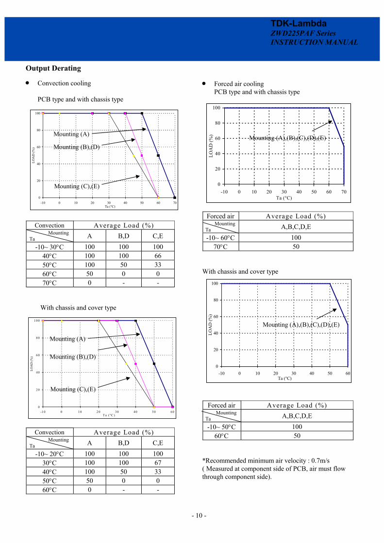
Output Derating
· Convection cooling PCB type and with chassis type
Convection Average Load (%)
Mounting Ta A B,D C,E
-10~ 30°C 100 100 100 40°C 100 100 66 50°C 100 50 33 60°C 50 0 0 70°C 0 - -
With chassis and cover type
Convection Average Load (%)
Mounting Ta A B,D C,E
-10~ 20°C 100 100 100 30°C 100 100 67 40°C 100 50 33 50°C 50 0 0 60°C 0 - -
· Forced air cooling PCB type and with chassis type
Forced air Average Load (%)
Mounting Ta A,B,C,D,E -10~ 60°C 100
70°C 50 With chassis and cover type
Forced air Average Load (%) Mounting Ta A,B,C,D,E -10~ 50°C 100
60°C 50 *Recommended minimum air velocity : 0.7m/s ( Measured at component side of PCB, air must flow through component side).
0
20
40
60
80
100
-10 0 10 20 30 40 50 60Ta (°C)
LOA
D (%
)
Mounting (A),(B)
Mounting (C),(D),(E)
0
20
40
60
80
100
-10 0 10 2 0 30 40 50 60T a (°C )
LOA
D (%
)
0
20
40
60
80
100
-10 0 10 20 30 40 50 60 70Ta (°C)
LOA
D (%
)
0
20
40
60
80
100
-10 0 10 20 30 40 50 60 70Ta (°C)
LOA
D (%
) Mounting (A),(B),(C),(D),(E)
Mounting (A),(B),(C),(D),(E)
Mounting (A)
Mounting (C),(E)
Mounting (B),(D)
Mounting (A)
Mounting (C),(E)
Mounting (B),(D)

- 11 -
TDK-Lambda ZWD225PAF Series INSTRUCTION MANUAL
4-2. Mounting Method PCB type
Please use the mounting holes (5 holes of f3.5) and insert the spacer (MAXf8.0)of height over 8mm to lift the unit. Also use all 5 mounting holes for the unit installation. The vibration test is taken when the unit is raised by 8mm spacers.
Please leave 4.5mm space from the unit surfaces and leave 4.5mm space from the sides of PCB. For the solder surface, 8mm space is necessary. If the space is not enough, the specification for insulation and withstand voltage will not be satisfied.
PE should be connected to the earth terminal of the apparatus. If not, the EMI noise and output noise will increase.
Hatching area is maximum permissible area of metal part for mounting.
For chassis option /L, chassis & cover option /A Recommended mounting by following holes A or B, to meet 19.6m/s2 vibration specification. Mounting direction (F) & (G) is prohibited as shown in section 4-1. A: Embossed tapped and countersunk holes by 4-M4 screws B: F4.5 holes and R2.25 slot hole by 3-M4 screws
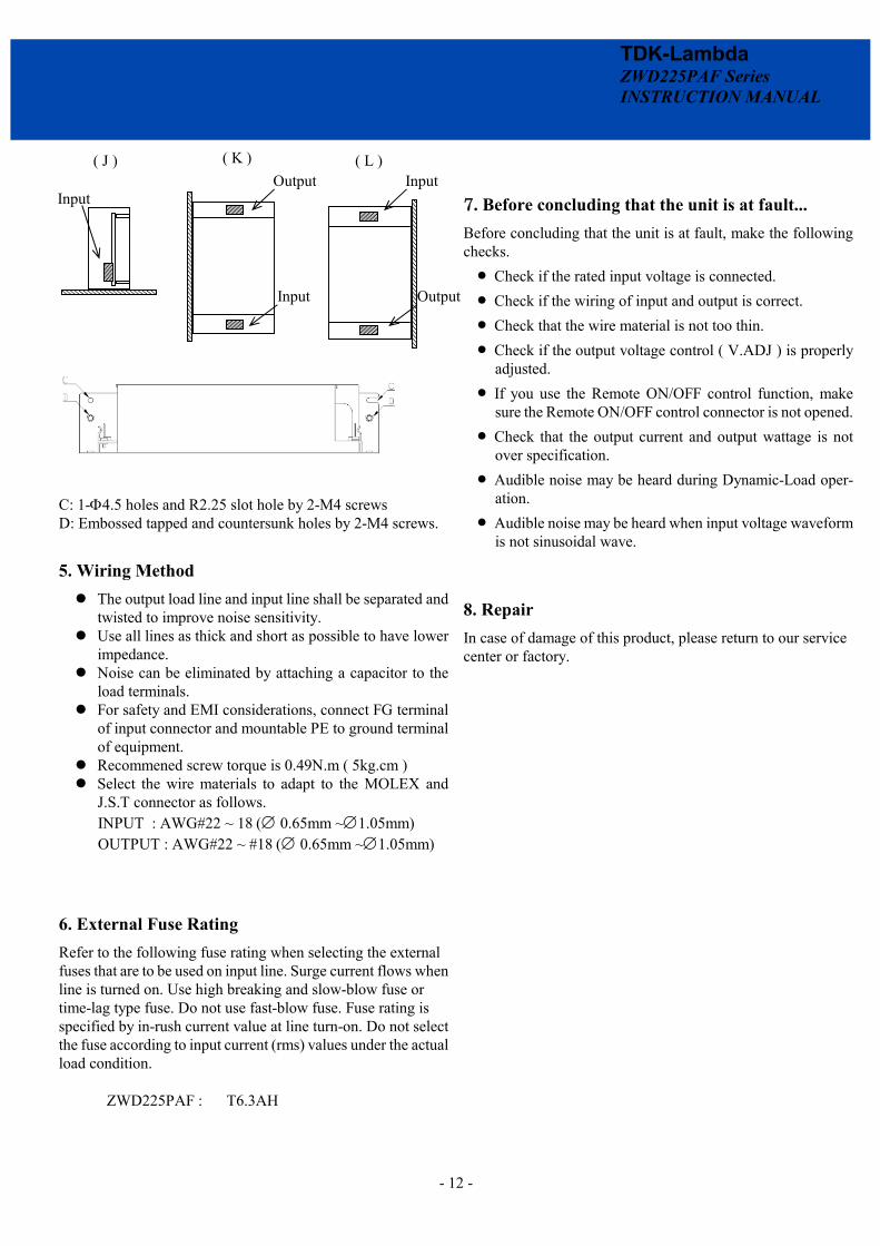
Mounting (F), (G), (H), (I) is prohibited. For mounting method (J), (K), (L), below, the vibration speci-fication is 4.9m/s2, mounted through holes C or D. Note: Output derating for mounting (J) is same as mounting (C). Output derating for mounting (K) is same as mounting (E). Output derating for mounting (L) is same as mounting (D).
PE
- 12 -
TDK-Lambda ZWD225PAF Series INSTRUCTION MANUAL
C: 1-F4.5 holes and R2.25 slot hole by 2-M4 screws D: Embossed tapped and countersunk holes by 2-M4 screws.
5. Wiring Method The output load line and input line shall be separated and
twisted to improve noise sensitivity. Use all lines as thick and short as possible to have lower
impedance. Noise can be eliminated by attaching a capacitor to the
load terminals. For safety and EMI considerations, connect FG terminal
of input connector and mountable PE to ground terminal of equipment.
Recommened screw torque is 0.49N.m ( 5kg.cm ) Select the wire materials to adapt to the MOLEX and
J.S.T connector as follows. INPUT : AWG#22 ~ 18 (Æ 0.65mm ~Æ1.05mm) OUTPUT : AWG#22 ~ #18 (Æ 0.65mm ~Æ1.05mm)
6. External Fuse Rating Refer to the following fuse rating when selecting the external fuses that are to be used on input line. Surge current flows when line is turned on. Use high breaking and slow-blow fuse or time-lag type fuse. Do not use fast-blow fuse. Fuse rating is specified by in-rush current value at line turn-on. Do not select the fuse according to input current (rms) values under the actual load condition.
ZWD225PAF : T6.3AH
7. Before concluding that the unit is at fault... Before concluding that the unit is at fault, make the following checks.
· Check if the rated input voltage is connected. · Check if the wiring of input and output is correct. · Check that the wire material is not too thin. · Check if the output voltage control ( V.ADJ ) is properly
adjusted. · If you use the Remote ON/OFF control function, make
sure the Remote ON/OFF control connector is not opened. · Check that the output current and output wattage is not
over specification. · Audible noise may be heard during Dynamic-Load oper-
ation. · Audible noise may be heard when input voltage waveform
is not sinusoidal wave.
8. Repair In case of damage of this product, please return to our service center or factory.
Input Output
Input
Input
Output
( J )
( K )
( L )