illumination system colibri.2 operating manual · introduction colibri.2 notes on device safety...
TRANSCRIPT

Illu
min
atio
n S
ystem
Colibri.2
O
peratin
g M
anual

Carl Zeiss Copyright / Trademarks Colibri.2
2 423052-7244-001 07/2014
Knowledge of this manual is required for the operation of the device. You are therefore requested to familiarize yourself with its content and pay special attention to the instructions regarding the safe handling of the device.
We reserve the right to make changes in the interest of further technical development. This manual is not subject to an update service.
© Unless expressly authorized, forwarding and reproduction of this document, as well as the utilization and communication of its contents are not permitted. In the event of failure to comply with this requirement, the violating party will be held liable for damage.
All rights reserved in the event of a patent approval or utility model registration.
All company and product names mentioned in this operating manual may be trademarks or registered trademarks. Reference to non-company products is made for information purposes only and constitutes neither an approval nor a recommendation.
Carl Zeiss Microscopy GmbH assumes no liability for the performance or use of such products.
Issued by: Carl Zeiss Microscopy GmbH Carl-Zeiss-Promenade 10 07745 Jena, Germany
[email protected] www.zeiss.com/microscopy
Carl Zeiss Microscopy GmbH Königsallee 9-21 37081 Göttingen, Germany
Number of this manual: 423052-7244-001
Date of issue: Version 2 - 07/22/2014
authorized dealer:Pulch + Lorenz GmbHAm Untergrün 23, 79232 MarchTel.: 07665 927 20www.pulchlorenz.de

Colibri.2 Contents Carl Zeiss
07/2014 423052-7244-001 3
CONTENTS
Page
1 INTRODUCTION ................................................................................................................ 5 1.1 Notes on device safety ........................................................................................................ 5 1.2 Warning labels ................................................................................................................... 9 1.3 Warranty notes................................................................................................................. 11
2 DESCRIPTION .................................................................................................................. 12 2.1 Name, intended use, and main features ............................................................................ 12 2.2 Components overview ...................................................................................................... 13 2.3 Technical data .................................................................................................................. 14
3 START-UP ....................................................................................................................... 15 3.1 Unpacking the illumination system .................................................................................... 15 3.2 Attaching the lamp module, connecting the control unit and the control panel .................. 16 3.3 Connection diagram ......................................................................................................... 17 3.3.1 Connection diagram for stand-alone operation.................................................................. 17 3.3.2 Connection diagram with PC and motorized microscope for Fast Acquisition ..................... 18 3.4 Construction of the illumination system ............................................................................ 19 3.4.1 Colibri.2 lamp module ...................................................................................................... 19 3.4.2 Control unit ..................................................................................................................... 19 3.4.3 Control panel ................................................................................................................... 20 3.4.4 External white light source ................................................................................................ 21
4 OPERATION .................................................................................................................... 22 4.1 Switching on the control unit ............................................................................................ 22 4.2 Functions of the control panel ........................................................................................... 22 4.3 Functions of the white light source HXP 120 V .................................................................. 23
5 MODIFYING THE LAMP MODULE .................................................................................. 24 5.1 Removing the lamp module from the microscope and opening it ....................................... 24 5.2 Inserting or changing LED modules ................................................................................... 25 5.3 Inserting or changing a mounting frame with beam combiner ........................................... 27 5.4 Inserting the beam combiner into the mounting frame or changing it ................................ 28
6 CONFIGURATION AND OPERATION IN MTB AND AXIOVISION .................................... 29 6.1 Configuration of LED modules, beam combiners and excitation filters ................................ 29 6.2 Operation via the AxioVision Software .............................................................................. 31 6.2.1 Microscope - Reflected Light Work area ............................................................................ 31 6.2.2 Alternative operating menu with graphical representation ................................................. 32
7 CONFIGURATION EXAMPLES OF THE LAMP MODULE ................................................. 34
8 CARE, CHANGE OF FUSES, AND SERVICE ...................................................................... 39 8.1 Care ................................................................................................................................. 39 8.2 Changing the fuses of the control unit .............................................................................. 40 8.3 Service ............................................................................................................................. 40

Carl Zeiss Contents / List of illustrations Colibri.2
4 423052-7244-001 07/2014
9 ANNEX ............................................................................................................................ 41 9.1 Property rights .................................................................................................................. 41
LIST OF ILLUSTRATIONS
Fig. 1-1 Warning labels on the Colibri.2 illumination system .............................................................. 9 Fig. 1-2 Warning labels and safety components on the Colibri.2 illumination system for laser
applications ...................................................................................................................... 10 Fig. 2-1 Components overview of the Colibri.2 illumination system ................................................. 13 Fig. 3-1 Attaching the illumination adapter ..................................................................................... 15 Fig. 3-2 Attaching the lamp module ............................................................................................... 16 Fig. 3-3 Connection diagram for stand-alone operation .................................................................. 17 Fig. 3-4 Connection diagram with PC and motorized microscope for Fast Acquisition ...................... 18 Fig. 3-5 Construction of the lamp module ...................................................................................... 19 Fig. 3-6 Control unit, front ............................................................................................................. 19 Fig. 3-7 Control unit, rear .............................................................................................................. 19 Fig. 3-8 Control unit, bottom ......................................................................................................... 20 Fig. 3-9 Control panel .................................................................................................................... 20 Fig. 3-10 Illumination system HXP 120 V, front ................................................................................. 21 Fig. 3-11 Illumination system HXP 120 V, rear .................................................................................. 21 Fig. 4-1 Control unit ...................................................................................................................... 22 Fig. 4-2 Control panel, with lamp module being controlled ............................................................. 22 Fig. 4-3 Various indications on the control panel display when using the
Colibri.2 illumination system and the white light source HXP 120 V, respectively ................. 23 Fig. 4-4 Illumination system HXP 120 V, front ................................................................................. 23 Fig. 5-1 Loosening fastening screws ............................................................................................... 24 Fig. 5-2 Removing the upper part of the housing ............................................................................ 24 Fig. 5-3 Inserting an LED module into the lamp module .................................................................. 26 Fig. 5-4 Changing a mounting frame with beam combiner ............................................................. 27 Fig. 5-5 Changing the beam combiner in the mounting frame ........................................................ 28 Fig. 6-1 Configuration via MTB2004 ............................................................................................... 29 Fig. 6-2 Configuration via MTB2004 ............................................................................................... 30 Fig. 6-3 AxioVision Software: Microscope - Reflected Light Tab Work area ...................................... 31 Fig. 6-4 Operating the LED modules in the illumination mode "Continuous" or "Gated" via a
separate operating menu .................................................................................................. 32 Fig. 6-5 Operating the external white light source via a separate operating menu ............................ 33 Fig. 8-1 Changing the fuses of the control unit ............................................................................... 40

INTRODUCTION Colibri.2 Notes on device safety Carl Zeiss
07/2014 423052-7244-001 5
1 INTRODUCTION
1.1 Notes on device safety
The Colibri.2 illumination system has been designed, produced and tested in compliance with the DIN EN 61010-1 (IEC 1010-1) standard - safety requirements for electrical measuring, control and laboratory instruments. It meets the EC requirements 2006/95/EC - Low-Voltage Directive - and 2006/95/EC - Electromagnetic Compatibility. The device has to be disposed of in accordance with the WEEE Directive 2012/19/EC.
It is marked with the sign.
The present manual contains information and warnings that have to be observed by the operator.
The warning and note symbols used in this manual are described below:
CAUTION This symbol indicates possible danger to the operator.
WARNING of possible laser radiation! The safety screws on the lamp module and Colibri.2 illumination adapter may only be removed by Carl Zeiss Service (not a customer interface). Otherwise there is a risk of eye damage upon laser coupling.
WARNING of possible laser radiation! The safety ring on the fiber coupling of the HXP light source may not be removed (not a customer interface). Otherwise there is a risk of eye damage upon laser coupling.
CAUTION LED radiation! LED risk group 3 according to DIN EN 62471:2009 when the user looks directly into the Colibri.2 light output. UV radiation is emitted. Any direct looking into the Colibri.2 light output is to be avoided. Failure to heed this caution may result in eye damage. Skin and eye irradiation is to be minimized by appropriate shielding.
CAUTION: High-energy UV radiation! Risk of damage to the eyes and skin!
CAUTION Disconnect the device from the line before any intervention!
ATTENTION This symbol indicates possible danger to the device or device system.
NOTE This symbol marks notes the operator must pay special attention to.

INTRODUCTION Carl Zeiss Notes on device safety Colibri.2
6 423052-7244-001 07/2014
The Colibri.2 illumination system is usually attached to the microscope stand. Depending on the design of the microscope, the risk for the user must be assessed as being markedly lower then.
When it comes to the intended use of the Axio Examiner microscope with Colibri.2, for example, the risk status of the overall system is downgraded to LED risk group 2 according to DIN EN 62471:2009.
The Colibri.2 illumination system including its original accessories may only be used for the purposes described in this operating manual.
Particular attention must be paid to the following notes:
Use the illumination system for Carl Zeiss microscopes only. The manufacturer cannot assume liability for any other applications, including that of individual modules or single parts. This also applies to any service or repair work that is not carried out by authorized service personnel. All warranty claims shall be forfeited.
To ensure safe operation of the illumination system in connection with the microscope, please pay attention to the operating manual of the microscope.
Do not operate the Colibri.2 illumination system in explosion-prone areas.
Keep combustible and easily inflammable materials away from the light beam and its surroundings.
The Colibri.2 illumination system is not equipped with any special devices for protection from substances that are corrosive, potentially infectious, toxic, radioactive, or other substances that could be hazardous to health. When handling such substances make sure that all legal regulations, particularly the relevant national accident prevention regulations, are observed.
The power plug of the control unit must be inserted in an outlet featuring a grounding (earth) contact. The grounding effect must not be made ineffective by an extension cable that does not have a protective ground wire.
When protection measures are found to be no longer effective, the instrument must be switched off and safeguarded against inadvertent operation. For repair please contact the Carl Zeiss Microscopy Service in Germany (see page 40) or your local Carl Zeiss representative.

INTRODUCTION Colibri.2 Notes on device safety Carl Zeiss
07/2014 423052-7244-001 7
Before switching on the control unit please check whether it is suitable for the available line voltage. Disconnect the power plug of the control unit before opening the device and before changing the fuses! Take care that only fuses for the rated power are used. Use of makeshift fuses and short-circuiting of the fuse holders are not permitted.
The lamp module, if equipped with the corresponding LED modules or if a white light source coupled by a liquid light guide is used, emits ultraviolet radiation that may cause burns to the eyes and skin. Therefore, never look directly into the light and avoid direct incidence of the light on your skin. When operating the microscope, always use the protective devices belonging to the instrument.
Never look into the light beam – neither with nor without optical instruments, even not if you simply want to observe the specimen. Your eyes may be damaged in case of non-observance!
Placing objects against or covering ventilation slats of the control unit may lead to heat build-up that may damage the device and, in extreme cases, cause a fire. Always keep the ventilation slats clear and ensure that no objects enter the device through the ventilation slats.
Dirt and dust may impair the performance of the device. Therefore, the device must largely be protected from these influences and covered with the dust cover when not being in use. Before covering the device, please make sure that it has been switched off.
Take appropriate protective measures if the specimen releases noxious gases, dust, and vapors, secondary radiation or explosive substances as a result of the UV radiation!
If an external white light source (e.g. HXP 120 V) is used in connection with Colibri.2, never look directly into the light guide output of the white light source to avoid the risk of being dazzled and going blind.
The white light source must not be switched on until after having connected the output of the liquid light guide tightly with the Colibri.2 system.
When using the white light source HXP120 V, please pay attention to the manufacturer's operating instructions.

INTRODUCTION Carl Zeiss Notes on device safety Colibri.2
8 423052-7244-001 07/2014
Opening the Colibri.2 Controller housing is only permitted to authorized service personnel.
The bulb of the external white light source has to be changed according to the operating instructions of the manufacturer of the white light source. Otherwise there is danger of burns and explosion when changing the bulb.
Defective devices must not be disposed of with the household waste. Dispose them of in compliance with the relevant legal requirements or return them to the manufacturer of the device.
The manufacturer of the device is under the legal obligation to take defective devices back.

INTRODUCTION Colibri.2 Warning labels Carl Zeiss
07/2014 423052-7244-001 9
1.2 Warning labels
Standard labeling
Fig. 1-1 Warning labels on the Colibri.2 illumination system

INTRODUCTION Carl Zeiss Warning labels Colibri.2
10 423052-7244-001 07/2014
Labels on the lamp module and Colibri.2 illumination adapter for laser application.
Fig. 1-2 Warning labels and safety components on the Colibri.2 illumination system for laser applications
The safety screws (Fig. 2-1/1 and 2) on the lamp module and Colibri.2 illumination adapter may only be removed by Carl Zeiss Service (not a customer interface). Otherwise there is a risk of eye damage upon laser coupling.
The safety ring (Fig. 2-1/3) on the fiber coupling of the HXP light source may not be removed (not a customer interface). Otherwise there is a risk of eye damage upon laser coupling.

INTRODUCTION Colibri.2 Warranty notes Carl Zeiss
07/2014 423052-7244-001 11
1.3 Warranty notes
The manufacturer guarantees that the device is free from material and manufacturing defects when delivered. Any defects have to be reported to us immediately and everything possible has to be done to minimize the damage. In the event that such a defect has been reported, the manufacturer is obligated to remedy it to its discretion by repairing the defective device or by delivering a perfect one. No guarantee is provided for defects caused by natural wear (wearing parts in particular) and improper use.
The manufacturer of the device is not liable for damage caused by faulty operation, negligence or any other tampering with the device, in particular as a result of removing or exchanging device components, or the use of accessories from other manufacturers. This forfeits all claims against warranty.
With the exception of the work specified in this manual, no maintenance or repair work to the microscopes may be performed. Repairs are only allowed to the Carl Zeiss service staff or specially authorized personnel. Should any defect occur, please contact first the Carl Zeiss Microscopy Service in Germany (see page 40) or your local Carl Zeiss representative.

DESCRIPTION Carl Zeiss Name, intended use, and main features Colibri.2
12 423052-7244-001 07/2014
2 DESCRIPTION
2.1 Name, intended use, and main features
Manufacturer's designation: Colibri.2 Illumination System
The Colibri.2 illumination system is designed to be used as a light source for reflected light fluorescence applications. It can be used in connection with the upright microscopes Axio Imager, Axioplan 2, Axioskop 2, Axioskop 2 FS, Axioskop 40, as well as with the inverted microscopes Axio Observer and Axiovert 200.
Major features are:
− High-end LED light source for fluorescence applications with visible and UV light for direct connection to the microscope
− Excellent contrast properties
− Up to four LED modules with different emission wavelengths can be used individually or combined in the lamp module
− LED modules are exchangeable, at present ten different LED modules are available
− No alignment required
− LED modules are equipped with a chip for automatic component recognition (ACR)
− LED emission is individually adjustable for every LED in one-percent steps
− Very quick switching on, over and off of the LED modules, no shutter required
− Optoelectronic switchover between LED modules, no mechanical movements
− Very long life time
− Minimum heat development
− Changeable beam combiners for the configuration of the light path in the Colibri.2 lamp module
− Specific filter sets (as P&C filter modules and separate excitation filters) for the LED modules deliverable
− Motorized interface for fiber coupling of an external white light source

DESCRIPTION Colibri.2 Components overview Carl Zeiss
07/2014 423052-7244-001 13
2.2 Components overview
Fig. 2-1 Components overview of the Colibri.2 illumination system

DESCRIPTION Carl Zeiss Technical data Colibri.2
14 423052-7244-001 07/2014
2.3 Technical data
Dimensions Lamp module (length × width × height) ....................................................... 240 mm x 155 mm x 75 mm Control unit (length × width × height) ........................................................... 225 mm x 250mm x 95 mm Control panel (length × width × height) ....................................................... 178 mm x 108 mm x 64 mm LED module (length × diameter) ...................................................................................... 53 mm x 31 mm Illumination adapter (length × diameter).......................................................................... 86 mm x 78 mm
Weight Lamp module ...................................................................................................................approx. 2400 g Control unit .....................................................................................................................approx. 2600 g Control panel .................................................................................................................... approx. 460 g LED module ........................................................................................................................ approx. 75 g Illumination adapter .......................................................................................................... approx. 550 g
Ambient conditions Transport (in packaging): Permissible ambient temperature .................................................................................... -40 to +70 °C
Storage: Permissible ambient temperature ................................................................................... +10 to +40 °C Permissible relative humidity (without condensation) ............................................. max. 75 % at 35 °C
Operation: Permissible ambient temperature ................................................................................... +10 to +40 °C Permissible relative humidity (without condensation) ............................................. max. 75 % at 35 °C Altitude of installation site............................................................................................... max. 2000 m Atmospheric pressure ......................................................................................... 800 hPa to 1060 hPa Pollution degree ............................................................................................................................... 2
Operating data Operating environment ........................................................................................................ closed room Protection class ...................................................................................................................................... I Protection type ................................................................................................................................ IP 20 Electrical safety............................................................ in compliance with DIN EN 61010-1 (IEC 61010-1) .............................................................................................................. including CSA and UL directives Overvoltage category............................................................................................................................. II Radio interference suppression ........................................................ in accordance with EN 55011 Class B Noise immunity .................................................................................... in accordance with DIN EN 61326 Line voltage range of control unit .................................................................... 100 to 240 V AC (± 10 %) Line frequency....................................................................................................................... 50 to 60 Hz Power consumption of control unit ................................................................................................ 70 VA
Fuses according to IEC 60127 Control unit ................................................................................................T 2.5 A/H; 250 V; 5 X 20 mm
Colibri.2 overall LED classification: .......................... LED risk group 3 according to DIN EN 62471:2009 LED module 365 nm .................................................... LED risk group 3 according to DIN EN 62471:2009 LED module 470 nm .................................................... LED risk group 1 according to DIN EN 62471:2009 LED module 619 nm .................................................. No LED risk group according to DIN EN 62471:2009

START-UP Colibri.2 Unpacking the illumination system Carl Zeiss
07/2014 423052-7244-001 15
3 START-UP
The Colibri.2 illumination system consists of the following main parts:
− Colibri.2 lamp module
− Control unit
− Control panel
The device can be assembled by the customer. The lamp module is completely mounted according to customers' order, including LED modules and beam combiners. If necessary, the LED modules and beam combiners can be changed quickly and easily by the customer (see Section 5). 3.1 Unpacking the illumination system
The lamp module, the control unit and the control panel, as well as the optional accessories are supplied separately in customary packaging.
Remove all parts from the packaging and check them for completeness according to the delivery note.
For use with confocal Laser Scanning Microscopes the illumination system Colibri.2 (Fig. 3-1/1) is delivered with tightly mounted illumination adapter (Fig. 3-1/2).
For laser safety reasons the connection between illumination adapter and lamp module is no customer interface. Disregard results in losing laser safety of the system.
The Colibri.2 lamp module can be only used with the upper part of its housing properly mounted. As soon as the upper part of the housing is removed, a safety switch (interlock) will switch off the LED modules.
Fig. 3-1 Attaching the illumination adapter

START-UP Carl Zeiss Attaching the lamp module, connecting the control unit and the control panel Colibri.2
16 423052-7244-001 07/2014
3.2 Attaching the lamp module, connecting the control unit and the control panel
The lamp module operates via the illumination mount (reflected light) of the microscope.
• Attach the lamp module (Fig. 3-2/1) via the dovetail of the illumination adapter to the reflected light mount (Fig. 3-2/4) of the microscope and fasten it by means of the clamping screw.
The lamp module does not require any adjustment.
• Connect the lamp module cable (Fig. 3-2/2) to the 25-pin subD port of the control unit (see Fig. 3-7/4).
• Connect the connection cable of the control panel (see Fig. 3-9/1) to the 15-pin subD port of the control unit (see Fig. 3-6/2).
• Connect the control unit (see Fig. 3-7/2) with the power cable to a power outlet.
An external white light source (e.g. HXP 120 V, see Fig. 3-10) can be connected at the coupling position for liquid light guides as follows:
• Introduce one end of the light guide into the white light source (see Fig. 3-11/3) and the other end into the connection point of the lamp module (Fig. 3-2/3) and fasten it by means of the swivel nut.
• The internal motorized shutter of the white light source HXP 120 V can be triggered via the 9-pin subD port of the lamp housing. Connect for this purpose the trigger cable with the BNC socket OUT 1 of the Colibri control unit (see Fig. 3-7/1).
• Connect the white light source (see Fig. 3-11/2) with a power cable to a power outlet.
Fig. 3-2 Attaching the lamp module

START-UP Colibri.2 Connection diagram Carl Zeiss
07/2014 423052-7244-001 17
3.3 Connection diagram
3.3.1 Connection diagram for stand-alone operation
Fig. 3-3 Connection diagram for stand-alone operation

START-UP Carl Zeiss Connection diagram Colibri.2
18 423052-7244-001 07/2014
3.3.2 Connection diagram with PC and motorized microscope for Fast Acquisition
* Colibri.2 can be connected alternatively via USB or via CAN!
Fig. 3-4 Connection diagram with PC and motorized microscope for Fast Acquisition

START-UP Colibri.2 Construction of the illumination system Carl Zeiss
07/2014 423052-7244-001 19
3.4 Construction of the illumination system
3.4.1 Colibri.2 lamp module
The Colibri.2 lamp module can be equipped with up to four LED modules (Fig. 3-5/1) and three beam combiners (Fig. 3-5/2).
The LED modules and beam combiners can be switched by the customer.
When using an additional fiber coupled white light source, it is possible to toggle between the lamp module and the external white light source by means of a motorized built-in switching prism (Fig. 3-5/3, covered).
3.4.2 Control unit
The control unit of the lamp module contains the control and the power electronics.
At the front of the device there is the ON/OFF switch Power (Fig. 3-6/1 with pilot lamp), as well as a 15-pin subD port (Fig. 3-6/2) for the control panel.
The rear of the control unit contains:
− several BNC ports; the trigger cable leading to the white light source has to be inserted in OUT 1 (Fig. 3-7/1)
− the power connection socket (Fig. 3-7/2)
− two CAN ports (Fig. 3-7/3) for the connection to the microscope
− the 25-pin subD port (Fig. 3-7/4) for connecting the Colibri.2 lamp module
− the USB port (Fig. 3-7/5) for the connection to a PC.
Fig. 3-5 Construction of the lamp module
Fig. 3-6 Control unit, front
Fig. 3-7 Control unit, rear

START-UP Carl Zeiss Construction of the illumination system Colibri.2
20 423052-7244-001 07/2014
The rating plate is located at the bottom of the control unit.
3.4.3 Control panel
The control panel can be used to control the LED modules, switch over to the external white light source, and control the shutter of the white light source HXP 120 V.
• The control panel has to be connected to the 15-pin subD port (see Fig. 3-6/2) of the control unit via the connection cable (Fig. 3-9/1).
Fig. 3-8 Control unit, bottom
Fig. 3-9 Control panel

START-UP Colibri.2 Construction of the illumination system Carl Zeiss
07/2014 423052-7244-001 21
3.4.4 External white light source
At the front of the white light source (illumination system HXP 120 V) there are
− the Power switch (Fig. 3-10/1), − the Brightness turning knob (Fig. 3-10/2) with
LED bar graph, − the Shutter button (Fig. 3-10/3) with the
Shutter open indicator (Fig. 3-10/4), − the Lamp Status indicator (Fig. 3-10/5), − and the Confirm Lamp Change button
(Fig. 3-10/6).
After the lamp has fired, the Lamp Status indicator shows the state of the internal operation- hour counter and therefore the age of the lamp in different colors:
Lamp Status indicator Internal operation-hour counter Comment
Green < 2000 hours
Yellow > 2000 hours Prepare lamp change
Red > 2500 hours Change lamp
Flashing red Lamp defective
At the rear there are the power connection socket (Fig. 3-11/2) and the fiber optics outlet (Fig. 3-11/3).
Besides that, the trigger cable port Trigger in (Fig. 3-11/4) is situated here. The trigger cable must be used to connect the HXP 120 V to the Colibri.2 control unit, if the shutter should be controlled via the Colibri.2 unit. If the shutter should be controlled by the microscope, the microscope has to be connected to the CAN port (Fig. 3-11/1) of the HXP 120 V.
If the HXP 120 V is used without the Colibri.2 lamp module, an illumination adapter is required to couple the liquid light guide into the reflected light path of the microscope (423302-0000-000 illumination adapter for light sources with light guide).
Fig. 3-10 Illumination system HXP 120 V,
front
Fig. 3-11 Illumination system HXP 120 V, rear

OPERATION Carl Zeiss Switching on the control unit Colibri.2
22 423052-7244-001 07/2014
4 OPERATION
4.1 Switching on the control unit
• Switch the Colibri.2 illumination system on/off by means of the ON/OFF switch Power (Fig. 4-1/1) at the front of the control unit.
As soon as the pilot lamp integrated in the switch is illuminated, the lamp module is ready for operation.
4.2 Functions of the control panel
The control panel is used to control the LED modules, to switch over to the white light source, and to check the shutter of the HXP 120 V.
When switching on the control unit, the system will be initialized, the LED modules present in the lamp module will be identified by ACR (automatic component recognition) and indicated on the 4-line display (Fig. 4-2/1 and Fig. 4-3/1, respectively).
In addition, the intensity for each LED module will be shown in percent and the switching status ON and - (for OFF) is indicated.
The LED modules are individually switched on/off by pressing the control elements 1 to 4 (Fig. 4-2/5) down. These control elements are also used to regulate the intensity by pushing them in the direction of the display or in the opposite direction.
The set brightness will remain temporarily stored even after switching off the respective LED module (i.e. unless the control unit is switched off). When this LED module is switched on again, it will illuminate with the same brightness as it did before it had been switched off.
To switch off all LED modules at the same time, press the All off button (Fig. 4-2/2).
The Ext. button (Fig. 4-2/3) is used to switch the prism to the external white light source, and the Shutter button (Fig. 4-2/4) functions to open/close the shutter of the white light source HXP 120 V. If another white light source is used, the Shutter button will have no function.
Fig. 4-1 Control unit
Fig. 4-2 Control panel, with lamp module
being controlled
OPERATION Colibri.2 Functions of the white light source HXP 120 V Carl Zeiss
07/2014 423052-7244-001 23
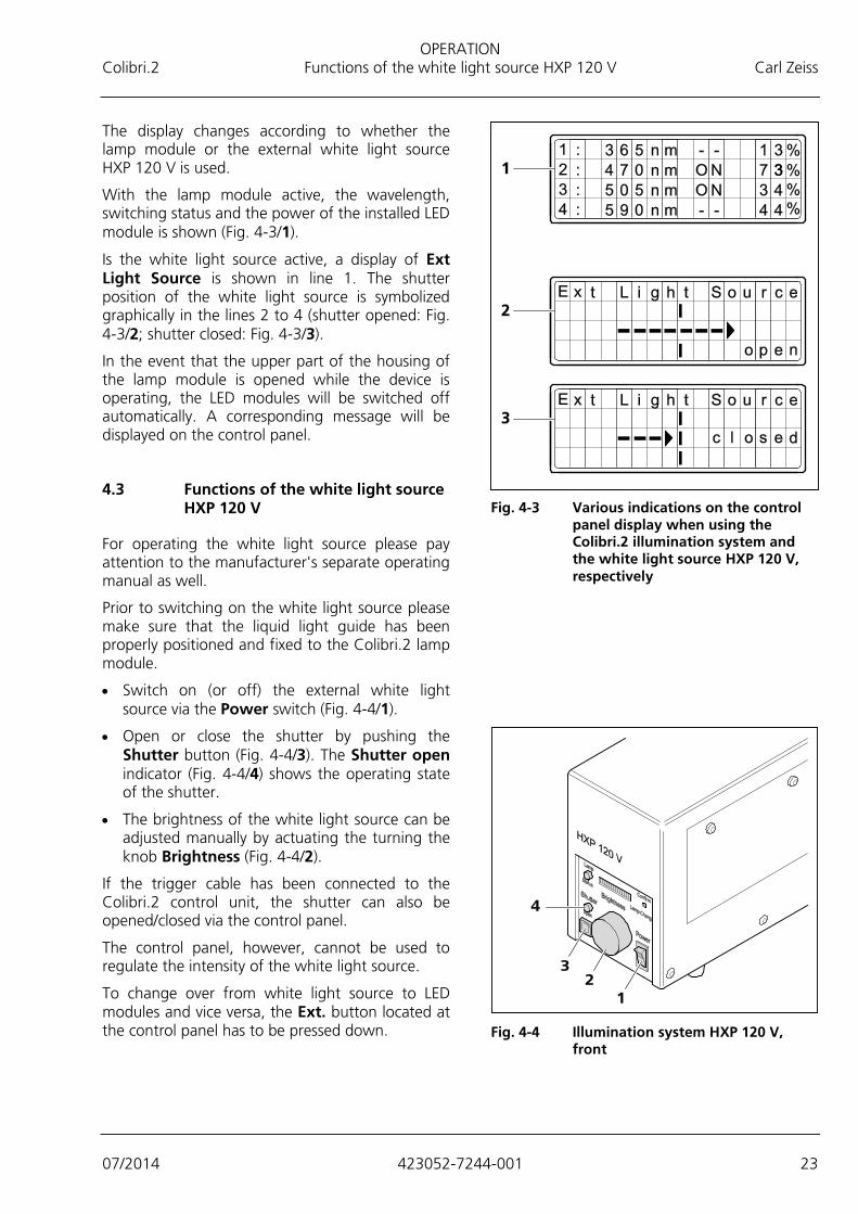
The display changes according to whether the lamp module or the external white light source HXP 120 V is used.
With the lamp module active, the wavelength, switching status and the power of the installed LED module is shown (Fig. 4-3/1).
Is the white light source active, a display of Ext Light Source is shown in line 1. The shutter position of the white light source is symbolized graphically in the lines 2 to 4 (shutter opened: Fig. 4-3/2; shutter closed: Fig. 4-3/3).
In the event that the upper part of the housing of the lamp module is opened while the device is operating, the LED modules will be switched off automatically. A corresponding message will be displayed on the control panel.
4.3 Functions of the white light source HXP 120 V
For operating the white light source please pay attention to the manufacturer's separate operating manual as well.
Prior to switching on the white light source please make sure that the liquid light guide has been properly positioned and fixed to the Colibri.2 lamp module.
• Switch on (or off) the external white light source via the Power switch (Fig. 4-4/1).
• Open or close the shutter by pushing the Shutter button (Fig. 4-4/3). The Shutter open indicator (Fig. 4-4/4) shows the operating state of the shutter.
• The brightness of the white light source can be adjusted manually by actuating the turning the knob Brightness (Fig. 4-4/2).
If the trigger cable has been connected to the Colibri.2 control unit, the shutter can also be opened/closed via the control panel.
The control panel, however, cannot be used to regulate the intensity of the white light source.
To change over from white light source to LED modules and vice versa, the Ext. button located at the control panel has to be pressed down.
Fig. 4-3 Various indications on the control
panel display when using the Colibri.2 illumination system and the white light source HXP 120 V, respectively
Fig. 4-4 Illumination system HXP 120 V,
front

MODIFYING THE LAMP MODULE Carl Zeiss Removing the lamp module from the microscope and opening it Colibri.2
24 423052-7244-001 07/2014
5 MODIFYING THE LAMP MODULE
Unplug the power plug of the microscope, the control unit and the connected white light source from the power supply before mounting/dismounting the lamp module to or from the microscope and before carrying out any modification! Disconnect the power plug of the control unit as well before changing the fuses! Make sure that only fuses for the rated power are used. Use of makeshift fuses and short-circuiting of the fuse holders are not permitted.
The lamp module is provided with an interlock switch that will disconnect the illumination system immediately as soon as the upper part of the housing is removed.
5.1 Removing the lamp module from the microscope and opening it
• Hold the lamp module firmly, loosen the clamping screw at the microscope coupling or at the illumination adapter (Fig. 5-1/2) using the SW 3 ball-headed screwdriver and remove the lamp module.
• Loosen both fastening screws (Fig. 5-1/1) at the lamp module.
• Place the lamp module safely on a suitable base.
• Pull off the upper part 1 of the housing (Fig. 5-2/1) upwards (the upper part 2 (Fig. 5-2/2) is firmly joined with the lower part and cannot be removed).
Fig. 5-1 Loosening fastening screws
Fig. 5-2 Removing the upper part of the
housing

MODIFYING THE LAMP MODULE Colibri.2 Inserting or changing LED modules Carl Zeiss
07/2014 423052-7244-001 25
5.2 Inserting or changing LED modules
To make them distinguishable, the LED modules are provided with adhesive labels where wavelength and part number are indicated. The mounts for the LED modules are marked with the position numbers to , corresponding to the numbers (1 to 4) on the control panel. If all LED modules are to be mounted, they should be inserted according to increasing wave lengths, beginning with position.
According to how the LEDs are combined, many different configurations are possible. Some configuration proposals are given in the overview of chapter 7.
• Insert the LED module (Fig. 5-3/1) into the mount up to the stop position (here, for example, the mount for channel ).
• Tighten the knurled screw (Fig. 5-3/2) slightly to hold the module in place.
• Connect the cable of the LED module (Fig. 5-3/3) to the corresponding socket. With the LED module inserted, the cable length allows only one plug-in position.
• Proceed in reverse order to dismount it: Press the clip of the plug and remove the cable from the socket. Loosen the knurled screw and pull the LED module out of the mount by pulling on the knurled screw.
• Do not pull the connection cable to remove the LED module.
• No adjustment is required after changing LED modules or beam combiners.
The bandwidth of an LED module can be restricted by using an excitation filter (diameter 25 mm). The filter has to be fixed by a retaining ring.

MODIFYING THE LAMP MODULE Carl Zeiss Inserting or changing LED modules Colibri.2
26 423052-7244-001 07/2014
Fig. 5-3 Inserting an LED module into the lamp module

MODIFYING THE LAMP MODULE Colibri.2 Inserting or changing a mounting frame with beam combiner Carl Zeiss
07/2014 423052-7244-001 27
5.3 Inserting or changing a mounting frame with beam combiner
• Hold the mounting frame (Fig. 5-4/1) by the grip and insert it from above into the corresponding seat (Fig. 5-4/2) of the lamp module until it locks in place (point of pressure). Avoid tilting the mounting frame to prevent damage.
• To change the mounting frame, hold it by the grip and remove it carefully upwards.
• The mounting frames are provided with an adhesive label indicating the wavelength of the inserted beam combiner (e.g. BC 490 for beam combiner 490 nm).
Fig. 5-4 Changing a mounting frame with beam combiner

MODIFYING THE LAMP MODULE Carl Zeiss Inserting the beam combiner into the mounting frame or changing it Colibri.2
28 423052-7244-001 07/2014
5.4 Inserting the beam combiner into the mounting frame or changing it
Different beam combiners are available to be inserted into the mounting frames marked with the corresponding wavelength designations.
The beam combiners are designed as high passes, which means that shorter wavelengths than that indicated for the beam combiner are reflected, while longer wavelengths can pass. For configuration proposals of LED modules and beam combiners see also chapter 7.
If both are ordered, the mounting frame will be delivered with the beam combiner already inserted.
If another beam combiner is required, an additional, empty mounting frame (423052-9110-000, mounting frame for beam combiner) must be ordered or an already mounted beam combiner must be dismounted.
To insert or change the beam combiner proceeds as follows:
Please handle the beam combiner and the mounting frame, respectively, with reasonable care, as these components can easily be damaged.
• Remove the mounting frame for the beam combiner (Fig. 5-5/1) carefully from the lamp module (see also Section 5.3).
• Loosen the screw (Fig. 5-5/3) and remove the beam combiner (Fig. 5-5/2).
• Carefully slide the new beam combiner underneath the spring-loaded frames (Fig. 5-5/4).
• Carefully re-tighten the screw (Fig. 5-5/3).
When mounted, the coated side of the beam combiner should point to the LED module with the shorter wavelength.
• Insert the mounting frame with the beam combiner again into the lamp module.
After completing the modification, assemble the lamp module again and mount it to the microscope.
Then, the lamp module can be used again (see Section 3).
Fig. 5-5 Changing the beam combiner in the
mounting frame
CONFIGURATION AND OPERATION IN MTB AND AXIOVISION Colibri.2 Configuration of LED modules, beam combiners and excitation filters Carl Zeiss
07/2014 423052-7244-001 29
6 CONFIGURATION AND OPERATION IN MTB AND AXIOVISION
6.1 Configuration of LED modules, beam combiners and excitation filters
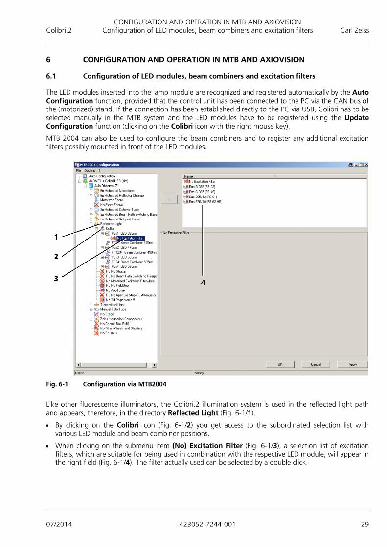
The LED modules inserted into the lamp module are recognized and registered automatically by the Auto Configuration function, provided that the control unit has been connected to the PC via the CAN bus of the (motorized) stand. If the connection has been established directly to the PC via USB, Colibri has to be selected manually in the MTB system and the LED modules have to be registered using the Update Configuration function (clicking on the Colibri icon with the right mouse key).
MTB 2004 can also be used to configure the beam combiners and to register any additional excitation filters possibly mounted in front of the LED modules.
Fig. 6-1 Configuration via MTB2004
Like other fluorescence illuminators, the Colibri.2 illumination system is used in the reflected light path and appears, therefore, in the directory Reflected Light (Fig. 6-1/1).
• By clicking on the Colibri icon (Fig. 6-1/2) you get access to the subordinated selection list with various LED module and beam combiner positions.
• When clicking on the submenu item (No) Excitation Filter (Fig. 6-1/3), a selection list of excitation filters, which are suitable for being used in combination with the respective LED module, will appear in the right field (Fig. 6-1/4). The filter actually used can be selected by a double click.
CONFIGURATION AND OPERATION IN MTB AND AXIOVISION Carl Zeiss Configuration of LED modules, beam combiners and excitation filters Colibri.2
30 423052-7244-001 07/2014
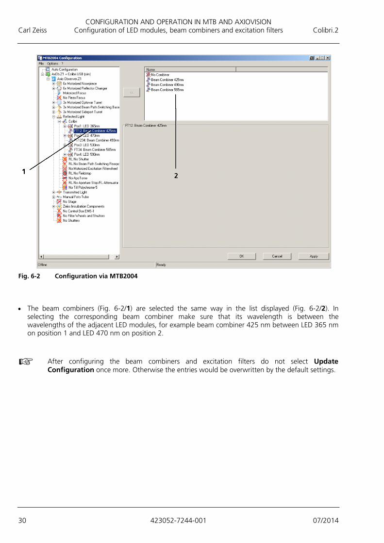
Fig. 6-2 Configuration via MTB2004
• The beam combiners (Fig. 6-2/1) are selected the same way in the list displayed (Fig. 6-2/2). In selecting the corresponding beam combiner make sure that its wavelength is between the wavelengths of the adjacent LED modules, for example beam combiner 425 nm between LED 365 nm on position 1 and LED 470 nm on position 2.
After configuring the beam combiners and excitation filters do not select Update Configuration once more. Otherwise the entries would be overwritten by the default settings.

CONFIGURATION AND OPERATION IN MTB AND AXIOVISION Colibri.2 Operation via the AxioVision Software Carl Zeiss
07/2014 423052-7244-001 31
6.2 Operation via the AxioVision Software
6.2.1 Microscope - Reflected Light Work area
1 LED module On/Off
2 Power in %
3 Overlaying the graphical representation
4 Switching off all LED modules
5 Selection between LED modules and external white light source
6 Selection between operating mode "continuous" and "gated" (light source waits for trigger signal)
7 Checking external shutter
Fig. 6-3 AxioVision Software: Microscope - Reflected Light Tab Work area

CONFIGURATION AND OPERATION IN MTB AND AXIOVISION Carl Zeiss Operation via the AxioVision Software Colibri.2
32 423052-7244-001 07/2014
6.2.2 Alternative operating menu with graphical representation
1 On/Off individually for each LED module
2 Setting of power in %
3 Schematic beam path
4 Selection between LED and external white light source
5 All LEDs On/Off
6 External white light source activated
7 Illumination mode "Gated" activated
Fig. 6-4 Operating the LED modules in the illumination mode "Continuous" or "Gated" via a separate
operating menu
If the illumination mode Gated has been selected, the beam paths appear as dashed lines. The system is waiting for a trigger signal.

CONFIGURATION AND OPERATION IN MTB AND AXIOVISION Colibri.2 Operation via the AxioVision Software Carl Zeiss
07/2014 423052-7244-001 33
1 External white light source activated
Fig. 6-5 Operating the external white light source via a separate operating menu
If the illumination is switched to the external white light source by clicking on External, the LED modules will be switched off automatically. The switching prism symbolized in the graphics changes its position to external. When switching back to LEDs, the shutter of the external white light source HXP 120 V will be closed automatically and the LED modules will be reset to the original operating state.

CONFIGURATION EXAMPLES OF THE LAMP MODULE Carl Zeiss Operation via the AxioVision Software Colibri.2
34 423052-7244-001 07/2014
7 CONFIGURATION EXAMPLES OF THE LAMP MODULE
Examples of configuration when equipping the lamp module with 4, 3, or 2 LED modules The LED modules and beam combiners printed in bold face refer to the corresponding example configuration displays (see below).
The LED modules in one box can only be used alternatively.
Example configuration
LED Pos. 1 BC 12 LED Pos. 2 BC 1234 LED Pos. 3 BC 34 LED Pos. 4
4 LED modules provided
1
365 nm
380 nm 400 nm
BC 425 455 nm
470 nm BC 490
505 nm 530 nm
BC 565
590 nm
615 nm
625 nm
3 LED modules provided
2 365 nm 380 nm
400 nm
BC 425 455 nm 470 nm
BC 490 empty empty 505 nm 530 nm
3
365 nm
380 nm
400 nm BC 425
455 nm
470 nm BC 490 BC 565
empty
590 nm
615 nm 625 nm
4 empty empty
365 nm 380 nm
400 nm
BC 425
BC 490
505 nm
530 nm BC 565
590 nm
615 nm
625 nm
5 empty empty 455 nm 470 nm
BC 490 505 nm
530 nm BC 565
590 nm 615 nm
625 nm

CONFIGURATION EXAMPLES OF THE LAMP MODULE Colibri.2 Operation via the AxioVision Software Carl Zeiss
07/2014 423052-7244-001 35
Example configuration
LED Pos. 1 BC 12 LED Pos. 2 BC 1234 LED Pos. 3 BC 34 LED Pos. 4
2 LED modules provided
6 empty empty empty empty
365 nm
380 nm 400 nm
BC 425
455 nm
470 nm 505 nm
530 nm
590 nm
615 nm
625 nm
6a empty empty
365 nm
380 nm 400 nm
BC 425 empty empty
455 nm
470 nm 505 nm
530 nm
590 nm
615 nm
625 nm
7 empty empty empty empty
365 nm
380 nm
400 nm
455 nm 470 nm
BC 490
505 nm
530 nm
590 nm 615 nm
625 nm
8 empty empty empty empty
365 nm
380 nm
400 nm 455 nm
470 nm
505 nm
530 nm
BC 565
590 nm
615 nm 625 nm

CONFIGURATION EXAMPLES OF THE LAMP MODULE Carl Zeiss Operation via the AxioVision Software Colibri.2
36 423052-7244-001 07/2014
Example 1: Example 2: Example 3:
Example 4: Example 5: Example 6:

CONFIGURATION EXAMPLES OF THE LAMP MODULE Colibri.2 Operation via the AxioVision Software Carl Zeiss
07/2014 423052-7244-001 37
Example 6a: Example 7: Example 8:
LED modules
Part number Designation Main wavelength Peak wavelength Half-width
423052-9011-000 LED 365 nm 360 – 370 nm 360 – 370 nm 8 nm
423052-9022-000 LED 350 nm 375 – 385 nm 375 – 385 nm 15 nm
423052-9031-000 LED 400 nm 390 – 410 nm 390 – 410 nm 15 nm
423052-9141-000 LED 420 nm 410 – 420 nm 410 – 420 nm 15 nm
423052-9131-000 LED 445 nm 450 nm 440 – 460 nm 24 nm
423052-9042-000 LED 455 nm 455 – 460 nm 450 – 455 nm 25 nm
423052-9052-000 LED 470 nm 470 – 475 nm 465 – 470 nm 30 nm
423052-9061-000 LED 505 nm 505 – 510 nm 500 – 505 nm 40 nm
423052-9072-000 LED 530 nm 530 – 535 nm 525 – 530 nm 45 nm
423052-9082-000 LED 590 nm 585 – 590 nm 590 – 595 nm 20 nm
423052-9091-000 LED 615 nm 615 – 620 nm 620 – 625 nm 20 nm
423052-9101-000 LED 625 nm 625 – 630 nm 630 – 635 nm 20 nm
423052-9121-000 LED 540 – 580 nm – – –

CONFIGURATION EXAMPLES OF THE LAMP MODULE Carl Zeiss Operation via the AxioVision Software Colibri.2
38 423052-7244-001 07/2014
Especially recommended filter sets for multi-channel fluorescence applications without switching the reflector turret
Part number Designation Examples of dyes
Components
489059-9901-000 Filter set 59 HE CFP + YFP shift free DMR 25
CFP YFP
2 excitation filters (single band), 1 beam splitter (dual band), 1 emission filter (dual band)
489060-9901-000 Filter set 60 HE CFP + YFP + HcRed shift free DMR 25
CFP YFP HcRed
3 excitation filters (single band), 1 beam splitter (triple band), 1 emission filter (triple band)
489061-9901-000 Filter set 61 HE shift free DMR 25 eGFP HcRed
2 excitation filters (single band), 1 beam splitter (dual band), 1 emission filter (dual band)
489062-9901-000 Filter set 62 HE shift free DMR 25 BFP GFP HcRed
3 excitation filters (single band), 1 beam splitter (triple band), 1 emission filter (triple band)

CARE, CHANGE OF FUSES, AND SERVICE Colibri.2 Care Carl Zeiss
07/2014 423052-7244-001 39
8 CARE, CHANGE OF FUSES, AND SERVICE
8.1 Care
Care of the device is limited to the following operations:
• Cover the device with the dust cover (microscope) after every use.
• Do not set up the device in a damp room.
• Remove dust and loose dirt from visible optical surfaces using a brush, a blowing brush, a cotton swab, optics cleaning paper, or a cotton cloth.
• Remove water-soluble dirt (coffee, cola, etc.) after breathing on it, using a dust-free cotton cloth or a moistened cloth. You can add a mild detergent to the water.
• Remove stubborn oily or greasy dirt (immersion oils, fingerprints) using a cotton swab or a dust-free cotton cloth dipped in the optics cleaning mixture L. This cleaning mixture is produced of 90 % by volume of gasoline and 10 % by volume of isopropanol (IPA). The individual components are also known under the following synonyms: Gasoline: Surgical spirit, petroleum ether Isopropanol: Isopropyl alcohol, dimethyl carbinol, 2-hydroxypropane
To clean the optical surface moves the swab or cloth in circles from the center to the edge of the optical surface. Slight pressure should be used on the optics during cleaning.
The control unit must be cleaned using a slightly moistened, not dripping cloth. Make sure that no humidity enters the device.
When using the device in warm and humid climatic zones, pay attention to the following instructions:
• Store the device in bright, dry and well-ventilated rooms with a humidity of less than 65 %; store particularly sensitive optical components and accessories, such as objectives and eyepieces, in a dry cabinet.
• When storing the device in closed cases for a longer period of time, the growth of fungus can largely be avoided by putting in cloths soaked in fungicide.
The risk of fungus growth on opto-mechanical instruments invariably exists in the following conditions:
− Relative humidity in excess of 75% and temperatures between +15 °C and +35 °C for more than three days.
− Installation in dark rooms without air ventilation.
− Dust deposits and fingerprints on optical surfaces.

CARE, CHANGE OF FUSES, AND SERVICE Carl Zeiss Changing the fuses of the control unit Colibri.2
40 423052-7244-001 07/2014
8.2 Changing the fuses of the control unit
The fuse holder is located at the rear of the control unit.
In case of a fuse failure, at first you should find the reason. If the failure is due to a technical fault, it has to be properly taken care of.
Before changing the fuses, disconnect in any case the power plug from the power supply.
• Disconnect the power plug.
• Pull the fuse holder (Fig. 8-1/1) out of the fusecompartment.
• Replace the defective fuse T 2,5 A/H.
• Push the fuse holder back into the fusecompartment until it locks into place.
• Connect the power plug again.
8.3 Service
Any intervention concerning optical components or moving elements inside the device, as well as any work on the power supply may only be performed by qualified service technicians or specially authorized personnel.
When service is required, please contact your competent local representative or
Carl Zeiss Microscopy GmbH Carl-Zeiss-Promenade 10 07745 Jena, Germany
[email protected] www.zeiss.com/microscopy
Carl Zeiss Microscopy GmbH Königsallee 9-21 37081 Göttingen, Germany
Fig. 8-1 Changing the fuses of the control unit

ANNEX Colibri Property rights Carl Zeiss
07/2014 423052-7244-001 41
9 ANNEX
9.1 Property rights
Devices, parts of devices or any procedures described in this manual are protected by the following patents:
US 6154282 A1 Semiconductor based excitation illuminator for fluorescence and phosphorescence microscopy.
authorized dealer:Pulch + Lorenz GmbHAm Untergrün 23, 79232 MarchTel.: 07665 927 20www.pulchlorenz.de
