imp feasibi llty study - nasa anchored imp orbit parameters (delta project office study). ..... 7...
TRANSCRIPT

X-672-64-4
IMP D&E FEASIBI LlTY STUDY
JANUARY 1964
d GODDARD SPACE FLIGHT CENTER
I, - GREENBELT, MARYLAND
https://ntrs.nasa.gov/search.jsp?R=19650010243 2018-07-03T00:16:35+00:00Z

I X-672-64-4
IMP D & E FEASIBILITY STUDY
Prepared by Paul G. Marcotte
GODDARD SPACE FLIGHT CENTER Greenbelt, Maryland

IMP D & E FEASIBILITY STUDY
SUMMARY i 1.
planetary Monitoring Platform (IMP) spacecraf t can be placed into a gravitationally anchored orbit about the moon by a thrust-augmented Delta (TAD) vehicle utilizing an X-258 third stage and a re t rorocket ( J P L apogee kick motor ) for lunar injection.
The IMP D&E feasibility study has revealed that a 181-pound In te r -
2. for achieving a stable lunar orbit a r e bet ter than 90 percent; 58 of the 100 s ta t is t ical cases employed would have a lunar orbi t lifetime of 180 days o r more.
In the improved nominal t ra jectory case , the success probabilities
3. Objectives of the satell i te a r e to investigate interplanetary magne- t ic fields, so la r plasma fluxes, so la r and galactic cosmic rays , and cosmic dust distributions and lunar gravitational field variations in the vicinity of the moon.
4. IMP- 1 components; ten other IMP components require some modifica- tion before being used in the I M P D&E. possible active thermal controllers, and some o r all of the experiments would be new to IMP; however, the kick motor and probably most o r all of the experiments selected would have pr ior successful flight experience on other satell i tes,
Ten of the basic I M P D&E spacecraf t components a r e identical to
The apogee kick motor ,
5. measurements on the front side and back side of the ear th and moon in respect to the sun thir teen times a yea r , where standard IMP satel l i tes will sample this region of the ea r th only once a year .
IMP D&E will be able to make scientific par t ic le and field
6. and gravitational f ield variations in support of future scientific and manned lunar explorations, In fact, most of the possible I M P D & E orbi ts will be adequate to obtain some measu re of the J coefficient of the moon's gravitational field, which would be of value in planning subsequent c loser orbits. of determining t e s se ra l harmonics which a r e of significant geophysical in te res t ,
The IMP D&E should supply ear ly knowledge of lunar environment
zonal harmonic 3
I M P D&E will have a f a i r change
7. basic I M P plasma and field measurements i n a unique way.
Being essentially lunar -anchored, IMP D&E will continue the
i

8. because no midcourse corrections a r e required.
The overall mission reliability i s ve ry high (be t t e r than 90 percent)
9. angle to 15 degrees, or a combination of both, i s required to optimize the probabilities of success . well within the capability of the Delta second stage.
A shor t coast phase (10-15 minutes) o r vehicle reorientation in pitch
This coast phase o r pitch maneuver i s
10. s t ra ted repeatedly. The Delta has been successful in the l a s t 20 out of 21 t imes; moreover , the Delta could have met the IMP D & E t r ans fe r orbi t launch window in 17 out of 21 launches.
The reliability of the Delta f o r such a s t ra ight shot has been demon-
11. and 2 hours in the improved nominal case , to f i r e the kick motor and achieve an acceptable and stable orbit.
The l u n a r injection window allows up to 1 hour in the nominal c a s e ,
12. The I M P D & E has fourfold redundancy in fir ing the kick motor.
13. instrumentation designs a r e completed, and much hardware is now available off the shelf , the total e f for t and funding should be minimized over that of an entirely new program. begin now on long-lead i tems and designs on a bas i s of noninterference with other established programs.
Owing to the fact that better than 75 percent of the s t ruc ture and
Moreover, l imited effort could
14. be successfully ca r r i ed out in a t ime period of 18 to 24 months af ter the experimenters were selected and funded.
If approved and properly supported, the IMP D & E mission could
.. 11

CONTENTS
1.
2 .
3.
4.
5.
6.
7.
Summary . . . . . . . . . , . . . . . . . . . . . . . . . . . . . . . . IN TROD UCTION. . . . . . . . . . . . . . . . . . . . . . . . . . . . GENERAL.. . . . . . . . . . . . . . . . . . . . . . . . . . . . . . . OB JEC T IV ES. . . . . . . . . . . . . . . . . . . . . . . . . . . . . . SPACECRAFT AND SUBSYSTEMS . . . . . . . . . . . . . . . LAUNCH . . . . . . . . . . . . . . . . . . . . . . . . . . . . . . . . . GROUND SYSTEMS . . . . . . . . . . . . . . . . . . . . . . . . . INFORMATION-PROCESSING S Y S T E M . . . . . . . . . . .
Page
1
1
3
13
15
35
41
43
Appendix I Success Probabilities for the IMP D & E Mission. . . . . . . . . . . . . . . . . . . . . . . . . . . . I- 1
Appendix I1 IMP D & E Orbital Study . . . . . . . . . . . . . . . . 11- 1
Appendix III Calculations of Perturbations of Lunar Orbi te rs 111-1
Appendix IV The Anchored IMP Scientific Mission. . . a . . . IV-1
Appendix V Detailed Weight Distribution for the IMP D & E Spacecraft e . . . . . . . . . . . . . . . . . . . . . . . . v - 1
Appendix VI IMP D & E Temperature Control. . . . . . . . . . . VI-1
Appendix VII IMP D & E Solar Paddles. . . . . . . . . . . . . . . VII-1
Appendix VI11 Transponder Power Required t o Track IMP D & E a t Lunar Distances. . . . . . . . . . . . . . . . . . . . VIII-1
Appendix IX Planning Information on the IMP D & E Mission and S-64 on De l t a . . . . . . . . . . . . . . . IX-1
iii

ILLUSTRATIONS
Figure
1
2
3
4
5
10
11
12
13
T ab1 e
1
2
3
4
5
6
I M P D & E Spacecraft (Side View). . . . . . . . . . . . Page
4
5
6
I M P D & E Spacecraft (Top View) . . . . . . . . . . . . Earth-Moon Transfer Orbit . . . . . . . . . . . . . . . . Nominal Anchored IMP Orbit P a r a m e t e r s (Delta
7 Project Office Study). . . . . . . . . . . . . . . . . . . . . Improved Nominal Anchored IMP Orbit P a r a m e t e r s (Special Pro jec ts Branch Study) . . . . . . . . . . . . . 8
2 0
2 1
I M P D & E Module and Facet Locations . . . . . . . . I M P D & E Module F r a m e Locations . . . . . . . . . .
25 I M P D & E View Angles. . . . . . . . . . . . . . . . . . . Approximate Initial Average Solar Ar ray Power
29
30
vs Spin Axis - Sun Angle . . . . . . . . . . . . . . . . . . I M P D & E P F M Telemetry Format . . . . . . . . . . . Word - E r r 0 r Probability Curve s for Rayleigh Noise . . . . . . . . . . . . . . . . . . . . . . . . . . . . . . . . . . . . . . . . . 3 4
38
39
Results of a Lifetime Study.. .................... IMP D&E Nosecone (Side View). . . . . . . . . . . . . . . . . .
TABLES Page
10 Delta Launch Vehicle Countdown Per formance . . . . . . . . 17
18
19
I M P - I . IMP D & E Component Comparison Lis t
Summary Weight Distribution fo r IMP D & E . . . . . . Weight Saving on IMP D & E Compared to IMP-I . . . Evaluation of Active Tempera ture Control Systems for the IMP D & E 23 . . . . . . . . . . . . . . . . . . . . . . .
28 I M P D & E Power Summary . . . . . . . . . . . . . . . . . iv

1. INTRODUCTION
1.1 OBJECT
This report , prepared at the request of Dr . John W. Townsend, Jr., Assistant Director for Space Sciences and Satellite Applications, pre - sents the resul ts of a study to determine the feasibility and desirabil i ty of placing an IMP-type satellite in orbit about the moon. assumptions were that a thrust augmented Delta (TAD) with an X-258 third stage would be the pr imary vehicle, a r e t r o kick motor equal o r s imi la r to the J P L Syncom B apogee kick motor would be used for lunar injection, and the IMP- I spacecraft hardware and instrumentation would be used a s much a s possible.
The basic
1.2 PURPOSE
In view of the fact that little is known about the lunar environment in respect to energetic particles, cosmic rays, cosmic dust, and magnetic and gravitational f ields, the mission of an IMP satell i te anchored in interplanetary space by the moon's gravitational field was proposed and the feasibility study initiated. should add significantly to man's scientific understanding of the ea r th ' s own satell i te (the moon), and should also establish environmental and gravitational field knowledge in support of future scientific and manned lunar explorations. It will also continue in a unique manner the long- t e r m measurements and monitoring of interplanetary conditions begun
The resul ts f rom this satell i te
by IMP-1.
1. 3 PART IC IPANTS
The IMP D & E feasibility study was conducted by the author with the ass i s tance of the Pro jec t Resources Office (T&DS), Space Sciences Division, Spacecraft Systems and Pro jec ts Division, Spacecraft Tech- nology Division, Theoretical Division, and Spacecraft Integration and Sounding Rocket - Division. by:
Major contributions to this study were made
J. Kork Appendix I, "Success Probabili t ies fo r the IMP D
R.K. Squires , R. Kolenkiewicz Appendix 11, "IMP D & E Orbital Study"
& E Mission' '
W . M. Kaula Appendix 111, "Calculation of Per turbat ions of Lunar Orbi te rs"
1

Dr. N. Ness
J. Webb
S . Ollendorf
L. Slifer, S. Mc Carron
G. C. Kronmiller
W . Schindler
R. Rochelle
Appendix Iv, "Anchored IMP Scientific Missions
Appendix V, "Detailed Weight Distributions for IMP D & E , " a l so mechanical layout and drawings
Appendix VI, "IMP D & E Tempera ture Control"
Appendix VII, "IMP D & E Solar Paddles"
Appendix VIII, "Transponder Power Required to T r a c k IMP D & E a t Lunar Distances"
Appendix I X , "Planning Information on IMP D & E"
Telemetry received power calculations
2

c
2. GENERAL The Goddard Space Flight Center proposes to anchor an IMP satell i te about the moon, to measure in detail the energetic par t ic le population, magnetic fields, and cosmic dust in this orbi t , and to explore the variations of the moon's gravitational field. The orbiting IMP will be anchored about the moon by the lunar gravity field and will be im- m e r s e d in essentially interplanetary space. The spacecraf t will be similar to the present IMP satellite and will weigh a total of 181 pounds.
The side and top views of the proposed IMP D & E a r e shown in Figures 1 and 2. rubidium vapor magnetometer has been deleted, an apogee kick motor added, and the individual fluxgate senso r s combined into one t r iaxial sensor package extending out f rom a paddle arm. motor , a heat shield was included, and it was necessary to move the antenna to the outer edge of the spacecraft .
It i s proposed that the IMP D&E be launched from Cape Canaveral during the calendar year 1966. The launch vehicle will be a thrus t - augmented Delta with an X-258 th i rd stage and a sma l l apogee kick motor s imi la r to the J P L kick motor used successfully in the Syncom B satell i te.
The major differences in appearance f rom IMP-I a r e that the
In adding the apogee
A typical sequence of launch events is shown in Figure 3. The f i r s t eleven s teps of injection into the t ransfer orbit a r e nominal Delta f i r s t , second, and third stage events. However, BTL cutoff is not cer ta in , and the second stage cutoff may have to be determined by the output f r o m an integrating accelerometer . booms, and solar paddles a r e re leased and locked into place in s e - quences 13 and 14. approximately 2 5 rpm. Separation of the third stage occurs next ( s tep 15) and the spin-stabilized satellite then coasts out to the lunar in te r - cept a r ea . F r o m actual tracking data, a s e t of lunar orbi t charac te r - i s t ics (F igures 4 and 5 ) i s generated. These curves a r e examined and a time to f i r e is selected to meet the mission objectives. mately 2 hours before time to f i r e the apogee motor, the command to s t a r t an electronic apogee sequence t imer i s initiated. t imer will initiate the f i r ing of the motor and the separation of the motor f r o m the spacecraft. If, according to telemetry data, the apogee motor has not f i r ed within the prescr ibed t ime, a d i rec t command to f i r e will be initiated, r ece ive r s , bypassing the t imer function, and will f i r e the motor. This method provides four opportunities to f i r e and separate the apogee kick motor. f i r ed before lunar intercept i n the optimized t ra jectory case. The time to f i r e the apogee kick motor is not cr i t ical and allows up to 1 hour (F igu re 4) in the nominal case and 2 hours (F igure 5) in the improved nominal case to achieve the desired range of lunar orbit character is t ics .
The fluxgate sensor and companion
This reduces the spin f rom a nominal 100 rpm to
Approxi-
This redundant
This signal will go through redundant command
The assumption here is that the r e t r o kick motor i s always
3

.
h
3
? a, .d
+J cr d k V a, V d a m w c a
I3
4
a, k
4

5

w V z 3 Y
g LA
I u Z 3 Q .J
w 4 o n. r
Y
V Y .^
+ u, n
6
\ bf
\ Oi \
\ Y
Y
a

100
90
80
70
60
50
40
30
20
IO
0
TYPICAL I HOUR INCLINATION (DEG.) L
4 T H STP FIRING W INDOL
PERICY N T H ION
70 72 I I I I
74 76 78 80 02
TIME (HOURS)
1.0
.8
.6
.4
.2
. I
0
Figure 4 - - Nominal Anchored IMP Orbit Parameters (Delta Project Office Study)
7

PERICYNTHION ( 103x K m )
NTHION ( lo3 x K m )
OdS 68 70 72 74 76
\
78
TYPICAL 2 - HOUR 4TH STAGE
FIRING WINDOW
1 00
90 -
TIME OF IMPULSE
Figure 5 Improved Nominal Anchored IMP Orbit P a r a m e t e r s (Special Projects Branch Study)
8
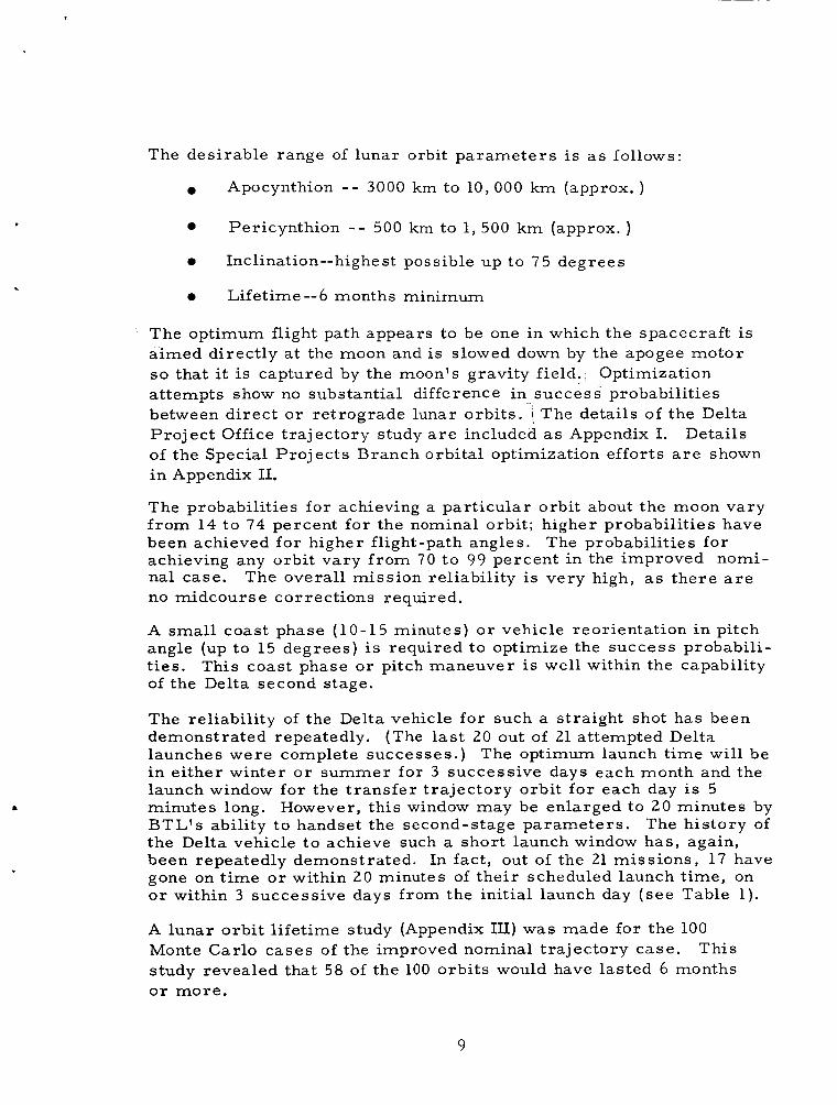
The desirable range of lunar orbit pa rame te r s i s a s follows:
Apocynthion - - 3000 km to 10,000 k m (approx. )
0
0
0 Lifetime--6 months minimum
Pericynthion - - 500 km to 1, 500 km (approx. )
Inclination--highest possible up to 7 5 degrees
The optimum flight path appears to be one in which the spacecraf t is a imed direct ly a t the moon and is slowed down by the apogee motor so that it is captured by the moon's gravity field. attempts show no substantial difference in success probabilities between d i rec t o r re t rograde lunar orbi ts . ; The details of the Delta Pro jec t Office t ra jectory study a r e included a s Appendix I. Details of the Special Pro jec ts Branch orbital optimization efforts a r e shown i n Appendix 11.
Optimization
The probabilities for achieving a par t icular orbit about the moon vary f rom 14 to 74 percent for the nominal orbit ; higher probabilities have been achieved for higher flight-path angles. achieving any orbit vary f rom 7 0 t o 99 percent in the improved nomi- nal case. no midcourse corrections required.
The probabilities f o r
The overall mission reliability i s very high, as the re a r e
A smal l coast phase (10 -15 minutes) o r vehicle reorientation in pitch angle (up to 15 degrees) is required to optimize the success probabili- t ies . of the Delta second stage.
This coast phase o r pitch maneuver is well within the capability
The reliability of the Delta vehicle for such a straight shot has been demonstrated repeatedly. (The last 20 out of 21 attempted Delta launches were complete successes . ) in either winter o r summer for 3 successive days each month and the launch window for the t ransfer t ra jectory orbit for each day is 5 minutes long. However, this window may be enlarged to 2 0 minutes by BTL's ability to handset the second-stage parameters . The his tory of the Delta vehicle t o achieve such a short launch window has , again, been repeatedly demonstrated. In fact , out of the 21 miss ions , 17 have gone on t ime o r within 2 0 minutes of the i r scheduled launch t ime, on o r within 3 successive days f r o m the initial launch day ( s e e Table 1).
The optimum launch t ime will be
A lunar orb i t l ifetime study (Appendix 111) was made for the 100 Monte Carlo cases of the improved nominal t ra jectory case. This study revealed that 58 of the 100 orbi ts would have lasted 6 months o r more .
9

a, V c i!
z k 0 k
%I
~
N d W .+
u o S h .5 e, Y a g c .- .2 4 x +
c
W
6 z
10

Ten of the basic IMP D & E spacecraft components a r e identical to IMP-I components; ten other IMP-I components require some modi- fication p r io r to use in I M P D & E. (different f rom IMP-I) would be the apogee kick motor and possible active thermal control lers . Syncom B. The proposed temperature control lers are s imilar to those used on the Atlas-Able 4 program. However, this program did not produce a successful satell i te, and as a resu l t no flight data a r e avail- able on this design. Some development and testing would be needed to incorporate active temperature control for IMP D & E. passive thermal control is adequate to meet the basic spacecraft mission if the initial lifetime spin axis-sun angle is maintained between 30 and 150 degrees , and only pericynthion-type shadows a r e encoun- tered. temperature controller (rotating vane) as an experiment on S -3c and/ or an ear ly IMP to flight-prove the design.
The only actually new i tems
The kick motor was used successfully on
However,
Consideration is being given to placing this type of active
11

,
3. OBJECTIVES
The pr imary goal of the IMP D & E will be to investigate interplanetary magnetic fields, so la r plasma fluxes, so la r and galatic cosmic rays, and interplanetary dust distributions in the vicinity of the moon. principal problem in cosmic electrodynamics is the interaction of a moving magnetized plasma and a solid object. definitively studied with IMP D & E satel l i tes whereby the interaction of the so la r wind and the moon can be studied without the complicating effects of a planetary magnetic field. and ionization chambers are included in the proposed instrumentation, as well as a cosmic dust detector and a t r iaxial fluxgate magnetometer. Information on the lunar ionosphere may also be obtained by analysis of the te lemetry data (e.g., entrance and exit times of the satell i te be- hind the moon).
A
This phenomenon can be
High-energy particle detectors
Performing simultaneous measurements in space with magnetometers and plasma and particle detectors on the IMP D & E and other space- c raf t will provide invaluable data on the propagation of so la r t ransient disturbances in interplanetary space. In addition, the anchoring of a satell i te in the lunar gravitational field will allow the magnetohydro- dynamic wake of the ear th in the interplanetary medium to be studied at lunar distances thirteen t imes a y e a r , instead of once a year as is the case of the standard IMP'S. A second major objective of the IMP D & E will be a detailed anal- y s i s of its orbital dynamics. the lunar gravitational field and will permit investigation of the mass distribution in the moon.
This will provide cr i t ical information on
IMP D & E will a lso a s s i s t in the determination of the earth-moon mass rat io and the figure of the moon. Accurate knowledge of the lunar gravitational field is important in determining the bulk proper- ties of the lunar body and the development of m o r e specific models of the lunar interior. Finally, detailed knowledge of the lunar gravita- t ional field will be of importance in future lunar missions requiring accura te t ra jectory orbit manuevers. A more extensive t reatment of the scientific justification for this mission is given in Appendix IV.
13

4. SPACECRAFT AND SUBSYSTEMS
4.1 ASSUMPTIONS
The basic assumption for the IMP D & E spacecraft w a s that the IMP-I s t ruc ture and instrumentation be utilized a s much a s possible. In r e - viewing the proposedIMP D & Espacecraf t , the following i tems were changes to the basic IMP-I satellite:
F o r the experiments, the rubidium vapor magnetometer, Chicago telescope, orthogonal Geiger counter, and Ames proton analyzer have been deleted. A full tr iaxial flux gate magnetometer is pro- posed in place of the Rb magnetometer. The proposed so lar wind experiment will have two sensors 180 degrees apa r t f rom one another, in place of the single one now used on IMP-1. ment, and one o r two cosmic-ray experiments (E vs dE/dX, o r a n ion chamber , o r both) a r e proposed to complete a typical experiment lineup.
A cosmic-dust experi-
The optical aspect system wi l l be identical to that used on IMP-I. The power system will be identical except that IMP D & E will have 3-mil glass instead of 12-mil glass on the solar paddles, owing to lack of trapped radiation about the moon.
There will be a small modification to the pr ime converter t o furnish m o r e power to the t ransmi t te r , since the t ransmi t te r will now require 6 watts output for the IMP D & E instead of 4 watts output for the IMP-I. The wiring harness will be modified for the new layout and the slightly changed experiments.
The te lemetry data system will be basically the same except for internal modifications in the reformatting of the information, The s a m e building block modules will be used throughout the encoder. The programming will be provided in three basic cards which wi l l include the undervoltage detector, fluxgate calibration,. kil ler - t imer s , and the apogee sequence t imer functions.
The performance parameter card i s essentially the same except for two added functions: the apogee-motor fir ing signal and the signal indicating separation f r o m the apogee motor.
The t ransmi t te r and range-rate package wi l l be identical with the exception of 2 watts additional output f rom the t ransmi t te r and the addition of a redundant command receiver .
The antenna i s a modified turnst i le which will be placed at the outer edge of the spacecraft instead of around the central boom as i s the case in IMP-I.
15

The only actually new i tems a r e the J P L apogee kick motor and pqssibly active thermal controllers. The J P L kick motor was successfully flown on the Syncom B satellite, and i s made by the J e t Propulsion Laboratory in California. Active temperature controllers will require development and testing, i f used. IMP-1 and the IMP D & E , and what change there i s should be accom- plished with a minimum of complications. comparison listing.
4.2 STRUCTURE
There i s not a g rea t deal of change between the
(See Table 2 for component
The IMP D & E structure i s essentially identical to the IMP-1 s t ruc- ture , except that i t will be smal le r in height, will have aluminum honeycomb and sheet-metal covers, and will have smal l conical a r e a s on the top and bottom of the spacecraft which can support active ther - mal-control rotating blades. will now come out of the bottom of the spacecraft instead of the top.
The pr ime converter chimney stack
Table 3 gives a summary of the weight distribution for IMP D & E. The total spacecraft weight, minus the motor systems, is 110 pounds. The apogee kick motor weighs 70.9 pounds. The detailed weight distribution is included a s Appendix V. Table 4 shows the weight saving on IMP D & E compared to that of the IMP-I spacecraf t . Figure 6 shows the proposed placement of the experiments and instru- ments within the IMP-type s t ructure . spacecraft facets. essentially the same instrumentation, much of the design, fabrication, and layout have already been accomplished.
Figure 7 i s a side view of the In utilizing the IMP-I basic spacecraft design and
4.2.1 Stabilization
Inertial stabilization of the satell i te spin axis will be accomplished by gyroscopic spin of the satellite. nominal 100 r p m to 2 5 rpm by means of deploying the booms and pad- dles . No yo-yo despin system wi l l be used. Calculations indicate that spin variations should not exceed *5 r p m f rom the nominal.
The satell i te will be despun f rom a
4.3 THERMAL CONTROL
The cr i t ical par ts within the spacecraft in r ega rds to low tempera ture operation appear t o be the cosmic r a y experiment (Facet A) which may be permanently damaged by tempera tures below -15°C and the encoder (Facet E) which goes out of calibration below 0°C; however, the encoder does function at lower temperatures . During the lunar t r a n s f e r with a sun angle looking down on top of the spacecraf t , the battery and the facets run at a low temperature somewhere between -10 to -20°C. i s due to the f a c t that the heat shield for the kick motor shades the top par t of the spacecraft ( s e e F igure 1). With a transDarent heat shield, these temperatures can be ra i sed to approximately t 3°C and t24"CJ util izing passive thermal control. During orbi t about the moon, with spin axis-sun angle res t r ic ted to variations f r o m 30 to 150 degrees , the
This
16

TABLE 2
IMP - I - IMP D & E COMPONENT COMPARISON LIST
IMP-1
Experiments Cosmic r a y Cosmic r a y Magnetic field Solar wind
Not onboar d
Optical Aspect Svstem
Power System Solar paddles (4)
P r i m e converter
Battery Solar a r r a y regulator Encoder converter M ult i convert e r Internal e lectr ical
Telemetry Data System Encoder and DDP
Programmer No. 1 and undervoltage detector
P rogrammer No. 2 , fluxgate cal. and kil le r-t ime r
P r o g r a m m e r No. 4 and apogee sequence t imer
P a r a m e t e r s card
I M P D & E
Approximately s ame Approximately same Triaxial fluxgate Approximately s ame
Cosmic dust
Same
Approximately same
Approximat e ly s ame
Same Same Same Same
Approximately same
Approximate ly s ame
Approximat e ly same
Approximat e ly same
Approximately same
Approximate ly same
Change
No Rb magnetometer Two senso r s instead of one New experiment
3-mil g lass instead of 12 mil More output power for t ransmi t te r
Modify harness to suit new layout and c i rcu i t ry
New format - simpler design, many sub- modules and compo- nents on shelf and checked out
Regrouped
Regrouped
Regrouped and new function
Add motor firing and separation signal
17

I M P - I T e lem e t r y Communi c ations and Range and Range-Rate System
T r ansmi tt er
R&RR 1 R&RR 2 R&RR 3 Command receiver
Antenna system
Structure
Apogee Kick Motor
Table 2 (cont'd.) IMP D & E
Approximately same
Same Same Same
Same as R&RR r e ceive r Approximately same
Approximately same
New
Change
6 -watt output i n st e ad of 4 watts
Added for redundancy
Moved to outer edge of spacecraf t Smaller height, aluminum covers , pr ime converter stack-out bottom JPL motor f i r e and proved out on Syncom
TABLE 3
SUMMARY WEIGHT DISTRIBUTION FOR IMP D & E IT EM
Zxper iments Cosmic r a y Cosmic r a y Magnetic field Solar wind Cosmic dust
lp t ica l Aspect System
Power System .. Solar Conversion !. Internal Electrical
re lemet rv Data Svstem
re lemet r y Communication Sy s tern
Space craf t Structure
6.7 2.0 5.5 7.0 4.5
25.7
35.8 4.9
Total (Spacecraft minus apogee motor )
4pogee Motor -
Total (Spacecraft plus apogee motor )
TOTALS
22.2 (allow- able )
1.8
40.7
7 .9
7.2
30.2
110.0
70.9
180.9
18

TABLE 4
WEIGHT SAVING ON IMP D & E COMPARED TO IMP-I
Fluxgate senso r s
Fluxgate signal processor
Chicago telescope and electronics
Geiger counter experiment
Plasma probe and electronics
Solar paddles
Digital Data Processor Mod B
Programmer No. 3
Aspect sensor guide
Paddle arms
Bias sphere
Despin assembly
Support tube
Rb magnetometer assembly
Ames experiment
P la t form and top cover
Pounds Saved
3 . 0
Change
Reduced
1.0 Reduced
7.6 Deleted
3.0 Deleted
1.6 Reduced
3.0 Reduced
1.0 De le t e d
.9 De let e d
.2 Reduced
.5 Reduced
.5 Deleted
.2 Deleted
.5 Reduced
5.7 Deleted
1.5 Deleted
2.0 Reduced
32 . 2

20
t I 9 a,

3 ! i! 3 a
$
E
i
k7 1 f
i
21

t
satell i te temperatures can be held to reasonable values of -5 to t5O"C using passive thermal control, if there a r e only perigee-type shadows of about 1 hour. l em occurs i f the spacecraf t has only passive thermal control. temperatures within the facets and the bat tery can drop to -30 to -40°C during long shadows. Pass ive thermal control will be used fo r the IMP D & E spacecraft to fulfil the basic 6-month mission l ifetime requi re - ments. satisfactory. Active thermal control by means of shut ters and rotating elements has been investigated ( see Appendix VI). These tempera tures can be con- trolled so that they a r e within a pract ical range (for example -10°C minimum f o r the cr i t ical par ts) . Inclusion of active temperature control of course necessitates a small weight penalty; however, active tempera- ture control can be included within the framework of the weight available. With a reduction in the size af the solar paddles and use of a titanium case for the kick motor , a higher basic spacecraf t weight can be allowed.
4.3.1 SDacecraft Temr,erature Control
F o r shadows longer than 1 hour, a severe cooling prob- The
Active thermal controllers will be used if the design proves
An evaluation was made of various active control sys tems for the IMP D & E spacecraft. Three cases were studied.
Case I -Shutters on s ides , rotating blades top and bottom
0 Case Ia - Shutters on s ides , passive coatings on top and bottom
0 Case 11 - Rotating blades on top and bottom, passive coating on s ides
Table 5 shows the summary of the evaluation of the three sys tems over the full range of spin axis-sun angles (0 to 180 degrees) for the nominal orbit , listing the advantages and disadvantages of each system.
For the purpose of choosing an adequate tempera ture control sys tem, a ground r u l e has been adopted which l imi t s the spin axis-sun angle to the 30- t o 150-degree range. ability t o maintain tempera ture l imits ,during the t ransfer phase and extended shadow orbi ts using the simplest , mos t reliable means.
The c r i t e r i a fo r such a sys tem should be i t s
4.3.1.1 Case I
Examination of Table 5 shows that Case I, using a total active system, maintains the minimum temperatures best , is lightweight (in that no heat shield is required) , but is most complex. As shown in Table 5, minimum temperatures in the facets fall t o -18°C if the spacecraf t were to enter the shadow a t 0-degree or 180-degree sun angles. This would not be the case, however, i f the sun-angle res t r ic t ion were im- posed. tained above -15°C. resu l t s in lower mean spacecraft t empera ture during shade periods.
The minimum tempera ture in the cr i t ical facets could be main- Case Ia is only a slightly l e s s complex system, but
22

0 a- Z E e = C
C
2 3

4.3.1.2 Case I1
Case I1 is a much s impler and m o r e reliable approach than Case I, the main consequences being lower mean orbital t empera tures during ex- tended shadows a t low sun angles, the need for a heat shield, and a r e l - atively wide swing in temperatures in the event of a failure.
As in Case I, the minimum facet tempera ture can be raised to proper levels during extended shade periods for all orbital altitudes by r e - stricting the spin axis-sun angle to 30 to 150 degrees. the band on the temperature swing during a failure mode (t5"C to t7O"C). The heat-shield requirement will not be a weight penalty since the r o - tating-blade temperature control sys tem is l ighter than the shutter system. each other. for hea te rs during the t ransfer phase, a s spacecraft t empera tures do not exceed the lower l imits.
This also closes
Thus, taken on a total-weight bas i s , the two sys tems approach The restr ic ted spin axis-sun angle a l so removes the need
In summary, the most worthwhile sys tem for the res t r ic ted spin ax is - sun angle mission involves the use of rotating elements mounted to the spacecraft top and bottom surfaces. However, i f this sys tem were chosen, and the sun-angle res t r ic t ion removed, the l ife of the space- craf t would be limited to either 100 percent sunlight or pericynthion shadow orbits. To circumvent this problem to include all shadow orbi ts for the nominal mission, a total active control sys tem similar to Case I would have to be applied.
4.3.2 Rocket Thermal Control
In order t o prevent severe cooling of the propellant during t ransfer t o the moon, super-insulation wi l l have to be applied to the case. tionally, a thermal cover of superinsulation may have to be provided over the nozzle to keep it at near propellant-case tempera tures a t the t ime of a r r iva l at the moon. There a r e no data available f rom the man- ufacturers at present which places a lower l imit on the mater ia l (carbon cloth and phenolic) or maximum allowable gradients in the nozzle. Tes t s on the mater ia l may prove that a coating of evaporated aluminum on both outside and inside surfaces of the nozzle will suffice.
Addi-
4.4 EXPERIMENTS
Four basic experiments are proposed for this mission: magnetic field experiment, solar wind experiment, cosmic r a y experiment (E vs d E / dX and/or a Neher-type ion chamber) and a cosmic dust experiment. Depending upon a finalized weight figure, possibly all five experiments will be used. A full description of the experiments is given below and the sensor look angles a r e shown in F igure 8.
24

I
2 5

4.4.1 Magnetic Field Experiment
A t r iaxial set of fluxgate sensors is used to measu re the three orthog- onal components of the vector magnetic field. the component of the magnetic field along i t s axis by detecting a second harmonic content in the secondary of the sensor t ransformer . The dy- namic range of the unit is *64 gammas on each component with a sensi- tivity of k0.5 gamma.
Each sensor measu res
4.4.2 Solar Wind Experiment
Two Faraday cup detectors will measu re the integrated f l u x of low- energy positive particles. to include all fluxes coming f rom directions within 30 to 150 degrees of the spacecraft spin axis. A set of grids in the sensor re jec ts e lectrons and low-energy ions while modulating the velocity of the f l u x to various levels. t rometer circuit for fluxes f rom 106 to 5 x 10¹⁰ par t ic les /crnZ/sec a t energies from 10 ev to 10 kev.
The field of view of the two senso r s is chosen
The detection of the modulated flux is achieved with an elec-
4.4.3 Cosmic Ray Experiment (E vs dE/dX)
A thin dE/dX crystal i s placed in coincidence with a thick total-energy scinti l lator. This experiment furnishes precision separation of protons, e lectrons, alpha par t ic les , and heavy p r imar i e s , and i s sensit ive down to v e r y small flux values. This provides a means of determining energy and charge spectra. regions 10 t o 100 Mev per nucleon. of singly charged particles.
Proton and alpha-energy sensit ivity covers the It a l so provides mass separation
4.4.4 Cosmic Ray Experiment (Neher -Type Ion Chamber)
This instrument measu res total ionization produced per unit of t ime in a unit volume of standard-density air. tains a constant calibration for extended periods of t ime, and i s intended to se rve as a basic radiation monitor.
It is s imple to operate, main-
4.4.5 Cosmic Dust Experiment
The cosmic dust experiment will measu re the momentum, kinetic energy, speed and approximate radiants of individual dust par t ic les detected by the senso r s over a long period of time. coincidence unit and comprises an acoustical sensor , an ionization sen- so r , and condenser sensor. signals wi l l reveal the kinetic energy and momentum. measurements between sensor elements will revea l the velocity, and approximate directions will be determined f r o m the ape r tu re look angles.
The cosmic dust sensor i s a
The pulse-height analysis of the sensor Elapsed t ime
26

4.5 INSTRUMENTATION
4.5.1 Optical Aspect System
The optical aspect system, a sun- and an ear th-aspect sensing system, will be identical to that flown on IMP-I.
4.5.2 Power System
The pr imary power sys tem consists of solar paddles, battery, and a solar a r r a y regulator with following converters to convert the pr ime system voltage to individual voltages used within the spacecraft . Solar paddles will be essentially those used on the IMP-I exceptfor 3-mil glass shielding, since there i s much l e s s radiation expectedabout the moon than about the earth, and the missionlifetime of 6 months requi res l e s s shielding.
A summary of the power estimated for the spacecraft is shown in Table 6, and the power output curves for a three-paddle and four-paddle configuration a r e shown in Figure 9. As seen f rom these curves, t h ree IMP-I paddles a r e marginal and four a r e m o r e than adequate to perform the mission a s estimated. The details of the three-paddle power calcu- lation a r e given in AppendixVII. The final solar a r r a y chosen can be optimized in paddle spa r angle and pitch angle so that four paddles smal- l e r than the IMP-I paddles could be used with a resultant weight saving.
The so la r - a r r ay regulator regulates the power output f rom the paddles and l imits the charging voltage to the battery. multiconverter, encoder converter, and the optical aspect converter a r e essentially the same a s those used in IMP-I except that more power out- put will be required f rom the prime converter to supply the t ransmi t te r for this particular mission and the individual converter voltages may have to be adjusted for the new experiments. The battery will be ident- ica l to that on the IMP-I satellite and the internal e lectr ical ha rness w i r - ing will be modified to adapt to the new spacecraft experiments and layout.
The pr ime converter,
4.5.3 Telemetry Data System
The existing and well-proven pulsed frequency modulation (PFM) te- lemetry sys tem will be employed. satell i tes to process both analog and digital data inputs f rom the var ious sensors . t o encode this information onto the te lemetry link. essentially a voltage -controlled oscil lator (VCO) for handling the analog inputs, and a digital oscillator to handle digital data inputs. tization of the analog data is accomplished on the ground during data processing. and 22 o r 44 bits per second fo r the analog experiments depending on whether burst-blank o r continuous t ransmiss ion is used for that par t i - cu la r experiment.
It i s uniquely designed for scientific
The system has been optimized in power, weight, and volume The system uses
The digi-
The bit ra te is 9 bits per second for the digital experiments ,
27

TABLE 6
IMP D & E POWER SUMMARY
Cosmic r a y experiment Cosmic r a y experiment Magnetic field experiment Solar wind experiment Cosmic dust experiment 0 pti c a1 aspe c t s y s t em Transmi t te r and range and range-
Command receiver No. 2 Encoder , D D P and converter Apogee sequence timer Pa rame te r c a r d Undervoltage detector sys tem Solar a r r a y regulator Bat tery M ulti convert e r P r i m e converter
r a t e system (6-watt radiated power)
Peak Power watts
3.6
3.7 14.8
Aver age Power (watts)
1.7 0.2 0.8 1.0 0.4 0.3
17.5 0.1 0 . 7 0 .6 0.05 0.20 0.24 1.00 3 .3
11.8
TotaI Average Power: Additional Peak Power : Total Peak Power:
39.89 t6.0 45.89
The telemetry encoder and digital data p rocesso r (DDP) will be modi- fied to f i t the new experiment lineup, and a typical te lemet ry format is shown in Figure 10. The encoder and DDP will use identical submod- ules t o those in IMP-I a r ranged i n a different o r d e r to suit the IMP D&E needs. The undervoltage detector, the fluxgate cal ibrator , and the apogee se - quence timer function will be combined within the IMP-I programmer c a r d s 1, 2 and 4. The same IMP-I performance pa rame te r ca rd will be used except that the functions concerning the firing and separating of the apogee motor will be added.
Three basic programmer c a r d s will be used in the satellite.
4.5.3.1 Telemetry Received Signal Power
Transmi t te r output power will be 6 watts, *57-degree phase-modulated signal is twice the c a r r i e r power, o r 4 watts.
The sideband power f o r a
P, = f 36.0 dbm
28

. L .
I1
m
0 DD
29

30

Transmitting-antenna gain includes the dipole gain, wir ing-harness loss, and c i rcu lar polarization loss.
Gt = -4 db
Receiving-antenna gain is based on the assumption that the 21 -db gain a r r a y of crossed-yagi antennas (NASA 16) will be used.
Gr = t 2 1 db
Attenuation due to the 250,000 nautical-mile maximum path loss is:
136 x 477 x 2.5 x 10 5 x 1853
= (3.80 x
19 = 1.44 x 10-
= 14.4 x )" = 1.6 -190 db
= -188.4 db
Substitution of the above factors in the received power equation yields:
2 W = P G G (") r t t r 4 n r
= + 3 6 . 0 -4 t 2 1 -188.4 = -135.4 dbm
= 2.9 x wat ts
4.5.3.2 Safety Margin
Sky-noise tempera ture at 136 Mc in the plane of the ecliptic has a n average value of about 600°K; however, there is a hot spot of about 2000°K looking toward the center of the galaxy.
The receiver-noise figure is 3 db. This corresponds to a rece iver - noise temperature of 290°K.
31

The noise temperature due to the ear th seen by the antenna side lobes and atmospheric noise is 55°K.
The noise temperature then becomes:
Tn = 600" t 290" + 55" = 945°K
A se t of 128 contiguous f i l ters will be used in the detection process during data reduction to enhance the output signal-to-noise ratio. The bandwidth of each fi l ter is 100 o r 6.25 cps.
16
The performance of the te lemetry sys tem can best be judged by knowing the probability of a word e r r o r as a function of a parameter that is in- dependent of the detection process . This parameter , p, is the received energy pe r bit divided by the noise-power-density Pn.
W r x T
Pn x n P =
where W r = received power
T = t ime length of word
Pn = noise power density
n = degree of coding
The power spectral density of the noise at the input to the receiver i s given by Pn = kT,
where k = 1.38 x watt seconds per degree
Pn = 1.38 x x 9 45°K
= 13.0 x watt seconds
The parameter P becomes:
2.9 x x 0.16
13.0 x l o m z 1 x 7 = 50.8 o r t B =
32
7. db

In Figure 11 a ver t ical line i s drawn corresponding to a value of ,B of 50.8 o r 17.1 db. At an e r r o r probability of one e r r o r in one thousand words, the safety margin that exists f o r a perfect comb fil ter i s 12 db.
4.5.4 Telemetry Communications and Range and Range-Rate System
The spacecraft t ransmi t te r functions as a PFM-PM telemetry t r ans - mi t te r and also a s a range and range-rate (R&RR) transponder. lunar orbit and during the ranging t ransmission, no telemetry data will be sent, and likewise during telemetry t ransmiss ion no ranging data will be transmitted. telemetry-data t ransmission will be determined at a la te r date. spacecraft t ransmi t te r will be identical to the IMP-I t ransmi t te r , ex- cept that the output power will be boosted f rom 4 watts to 6 watts. i s required for both telemetry and R&RR functions. for a detailed R&RR power calculation.) identical to IMP-I, except that an additional command receiver will be added for redundancy. will be located on the outer periphery of the spacecraft .
In
The optimum time sequence of the R&RR ve r sus the The
This (See AppendixVIII
The R&RR system will be
The antenna will be a modified turnsti le and
3 3

- ST - - ENERGY PER BIT ’ = NOISE POWER DENSITY (N/B)
Figure 11-- Word-Error Probabili ty Curves for Rayleigh Noise
34

5. LAUNCH
5.1 ORBIT AND TRAJECTORY CONSIDERATIONS
A nominal typical flight plan f o r this mission was prepared by the Delta Project Office and a s imilar plan was worked out by the Douglas Aircraft Company. The two compared favorably, although the Douglas Company was more conservative in their approach. However, proba- bility resul ts agree satisfactorily when compared on a common basis ( s ee Appendix I). Spacecraft weight and vehicle feasibility for this mission is reconfirmed by the Delta project office in Appendix IX. The Special Projects Branch ran studies which confirmed the above work and improved the success probabilities by improving the t ransfer t ra jectory.
A nominal orbit and the probabilities of achieving a lunar orbit f rom the nominal orbit were computed (Appendixes I and 11). motor was f i red at 1-hour intervals for the nominal case. nominal orbit, the probabilities for achieving a par t icular orbit varied f r o m 14 to 74 percent; however, higher probabilities have been achieved for higher flight-path angles. Probabilities for achieving any orbit about the moon vary f rom 70 to 99 percent in the improved nominal case. The overal l mission reliability is very high a s there a r e no mid-course c o r - rections required. orientation in pitch angle (up to 15 degrees) is required to optimize the success probabilities for the t ransfer t ra jectory. This coast phase o r pitch maneuver i s well within the capability of the Delta second stage. The reliability of the Delta vehicle for such a straight shot has been demonst rated repeatedly .
The fourth-stage F o r the
A small coast phase (10-15 minutes) o r vehicle r e -
The basic flight plan, shown i n F igure 3 , is as follows
(a) F r o m the la tes t performance figures of the TAD and the X-258, and the spacecraft final weight, an optimum nominal t ransfer t ra jectory will be generated.
(b) The vehicle will be launched into this optimum nominal t ra jectory.
(c) The spacecraft/fourth-stage combination i s boosted into the t r ans - fer t ra jectory by the X-258 and, af ter separation, coasts out to the lunar intercept a r e a while spin-stabilized at 25 rpm.
(d) Depending upon the performance of a l l s tages and the pointing accu- r a c y obtained, the t ransfer trajectory will follow the optimum nominal t ransf e r t ra jectory within certain deviations.
35

(e) The spacecraft will be tracked by range and range-rate and other tracking systems; a se t of orbital pa rame te r s and lifetime contour: will be generated and improved almost continuously during the approximately 70-hour t ransfer t ra jec tory flight t ime.
I
( f ) manager and project scientist will fourth stage.
F r o m the la tes t lunar parameter and l ifetime data, the project select the optimum t ime to f i r e the
(g ) The command to initiate the apogee sequence t i m e r will be given two hours before optimum kick-motor f i r e t ime.
(h) Functioning of the t imer during the 2-hour interval will be confirmed by telemetry. If confirmation of kick-motor firing is not received within appropriate tolerances, a d i rec t command to f i r e the motor will be initiated.
(i) This direct command bypasses the t imer function and f i r e s the motor igniter as a direct output f rom one of the command rece iver channels. This system allows a fourfold opportunity to f i r e the motor .
The launch window for the t r ans fe r t ra jec tory , it should be pointed out, occurs fo r only 3 succeeding days a month, and then fo r only 5 minutes a day during these 3 days. The launch window can be enlarged up to 20 minutes a day by BTL ' s ability to handset the t ra jec tory parameters . However, to achieve a desirable range of spin-axis sun angles (between 30 and 150 degrees for purposes of power, experiment look angle, and tempera tures) , launch must be made in e i ther December o r June to achieve the f i r s t 4 months of orbital l i fe within these spin-axis requi re - ments . 3 months within the desired spin-axis sun angle.
Launching the following month would resu l t in only the init ial
The launch window for lunar injection i s not c r i t i ca l , and excellent orbi ts can be obtained during a 1-hour period in the nominal ca se o r a 2-hour period in the improved nominal case .
5.2 ORBIT LIFETIME CONSIDERATIONS
A Runge-Kutta integration of the Lagrangian planetary equation was ca r r i ed out for the 100 orbi ts of the improved nominal t r ans fe r t r a j ec - to ry (Appendix 111). ing function is the ear th effect, which is long-periodic with respect to both the lunar satell i te and the earth-moon orbi t . The r e su l t s , shown
F o r these orb i t s , the important pa r t of the dis turb-
36

in F igure 12, may be summarized as follows: Out of 100 orbits con- sidered, 92 orbits survived 40 days; 75, 80 days; 67, 120 days; 61, 160 days; 56, 200 days; 48, 300 days; and 43, 400 days.
5 .3 LAUNCH VEHICLE
The launch vehicle for the Lunar IMP will be a thrust-augmented Delta utilizing an X-258 third stage and a JPL kick motor for the fourth stage. The launch configuration is shown in Figure 1 3 . P r i m e contractor for this th ree -stage launch vehicle is the Douglas Aircraf t Company.
37

: 0 03 0
0
1 cu 0
0 3 d a,
5 w 0
0 9 m
0 N m
0 a3 N
0 lz
0 0 cu
0 9 -
0 hl -
0 03
0 -t
0
. . a,
cdw
3NIAIAtlnS SlI980 A 0 l N 3 3 8 3 d
38

1 3.500
t
SUBSYSTEM PACKAGE
X-258 MOTOR 1
JPL STARFINDER
ANTENNA (4
I 0 0 0 0 0 00001
1 I
7: REF
SEPARATION PLANE STATION 256.794
\ FLUXGATE SENSOR
MOTOR
Figure 13 - - IMP D & E Nosecone (Side View)
39

6. GROUND SYSTEMS
6.1 LAUNCH SUPPORT EQUIPMENT
The Atlantic Missile Range and the launch vehicle contractor, Douglas Aircraf t Company, will supply suitable personnel t o handle the following tasks :
0 Assemble the Delta launch vehicle
0 Assume responsibility for checkout of the vehicle 's t r ansmi t t e r s and range safety beacon
0 Prelaunch checkout and launching the vehicle
GSFC will be responsible f o r delivery of the completedIMP D & E satell i te to the Atlantic Missile Range, and for an operational checkout of the satellite af ter installation of the launch vehicle. the satell i te before launching will be made at a t ime break in the count -down.
The final t e s t of
6.2 SPACECRAFT GROUND TEST EQUIPMENT
The equipment of the IMP D & E te s t stand is divided into five major categories :
Transducer s imulators - and simulated sources , such as radio- active and light sources to energize t ransducers of some space- c raf t experiments. (Current inputs and count inputs a r e used as s imulators for other experiments.)
Spacecraft control and monitoring equipment - such a s block- house control unit, external power supplies, and high-accuracy vol tmeters
Signal receiving and storage - included he re a r e equipment for receiving, displaying, and demodulating the phase -modulated c a r r i e r , and for R F frequency and power measurements , as well as WWV t ime signals, and tape r eco rde r s
P F M decoding to extract channel, f rame, and mas te r - f r ame synchronization signals, and generate gates t o select any des i red channel for examination and printout
Experiment logic decoding - collects PFM-to-digital decoder outputs, r e s to re s original format , and converts to equivalent decimal f o r m (P rogrammers a r e used to identify the experiments being transmitted, select proper conversion format , and provide inputs to printout equipment.)
41

6.3 TRACKING OPERATIONS
The IMP D & E satell i te will utilize a range and range-rate transponder. The Orbiting Geophysical Observatories (S-49/50) ground stations will be employed for range and range-rate tracking.
, At launch, early tracking data will be collected by Ascension Island and Johannesburg. Azusa and other Atlantic Missile Range r ada r informa- tion will be available to GSFC for incorporation into a computer pro- gram. The vector information f rom the AMR rada r t r ack on range and velocity of the booster stages will provide inputs for computing the ini- tial injection-point velocities of the spacecraft to a nominal orbit, a f te r which data f r o m the range and range-rate and Minitrack stations will be added into the computer problem to co r rec t the orbit calculations. the tracking stations receive additional data, the accuracy of the cal- culated parameters of the orbit will be continuously improved.
6.4 TELEMETRY OPERATIONS
A s
Three r e c eiving stat ions ( W o ome r a , Australia ; J o hanne s bur g , Africa; and Santiago, Chile) a r e properly equipped and spaced longitude to record the te lemetry signal for most of the t ime.
South in These
telemetry-receiving antennas have 21 -db gain, and may be circular ly polarized. with their capability using the following receiving antennas: 40 -foot dish, 21-db gain; 85-foot dish, 27-db gain; 16-yagi l inear ly polarized 21-db gain. 6 months and periodically thereaf ter a s required by the project scientist .
Other stations may be utilized a s required in accordance
Present plans a r e to record te lemet ry continuously for
The minimum expected life of the spacecraf t is 6 months.

7. INFORMATION -PROCESSING SYSTEM
7.1 GENERAL
The information-processing system designed to t r e a t the IMP satell i te data is identical t o the IMP-I information processing
7.2 OBJECTIVES
D & E system.
The objective of the IMP D & E information-processing system is to provide the scientist with precise data f rom his experiment in as short a t ime a s possible in the most useful format . Inherent in the system is the utilization of high-speed electronic data-processing machinery (EDPM) and high-performance analog-to-digital conversion equipment. The principal operation i s one of conversion of telemetry-tape signals, representing ei ther encoded digital data o r continuous signal data, t o a universal digital representation. netic tape in a fo rm suitable for handling by EDPM. The operations of checking, editing, putting into format, and scattering of an individual exper imenter ' s data is an internal operation in a medium-scale computer.
This information is recorded on mag-
The basic output of the sys tem w i l l be in two fo rms : tape in IBM high- o r low-density bit modes with formats (binary coded decimal) suitable for computer analysis, using an algebraic compiler language such as FORTRAN; and accompanying paper printouts of the tape information in a format bearing a one-to-one correspondence with the tape recorded format. If necessary, additional o r complementary output media will be provided upon special request f rom the experi- men te r and approval by the project staff.
computer magnetic
7 . 3 SCIENTIFIC EXPERIMENTAL DATA
Each experimenter will receive his experimental information with ac - cura te t ime reference. There will be no scaling of the information in o rde r to re turn the processed analog data to i t s original f o r m (i.e., a voltage f rom 0 to t 5), but a calibration and scaling procedure (mathe- matical formula and e r r o r analysis) will be provided.
No merging of scientific data with t ra jectory information will occur directly in the IMP D & E information-processing sys tem (IPS). The justification for not merging th is information by the sys tem is that the t ra jec tory data normally undergoes a s e r i e s of modifications and r e - finements before finalization. Hence, the scientific data will be ready fo r distribution t o the experimenters before the t ra jectory and orienta- t ion information is available. In the initial s tages of data analysis, it is not necessary for the experimenter to know precisely where the space- craft is located o r oriented. Interpretation and correlation of scientific data among the experimenters can proceed a t a rapid rate even when an accurate t ime reference alone is provided.
43
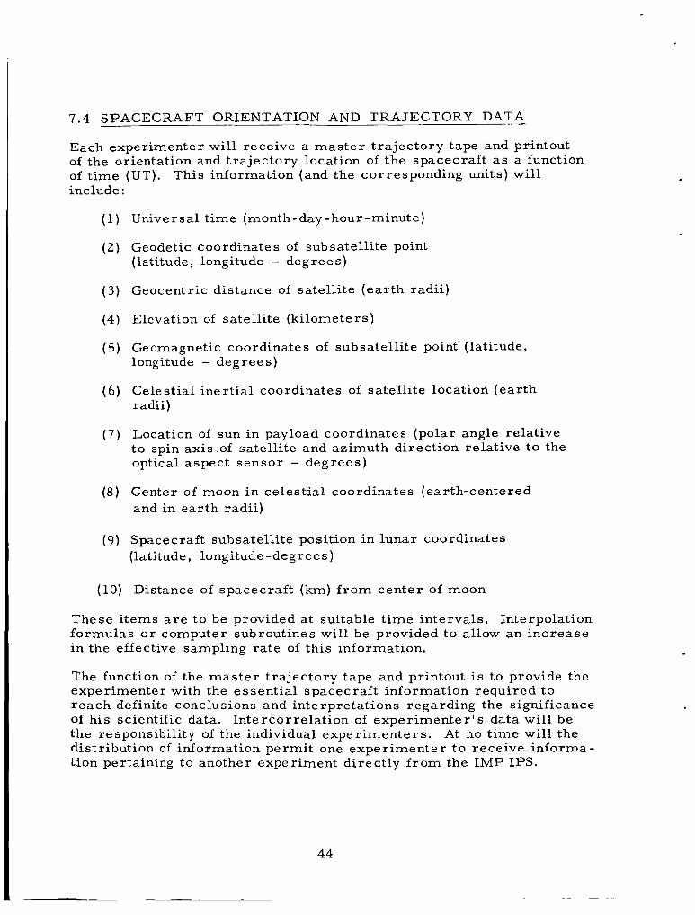
7.4 SPACECRAFT ORIENTATION AND TRAJECTORY DATA
Each experimenter will receive a m a s t e r t ra jectory tape and printout of the orientation and t ra jectory location of the spacecraft as a function of t ime (UT) . include :
This information (and the corresponding units) will
Universal t ime (month-day - hour -minute)
Geodetic coordinates of subsatellite point (latitude, longitude - degrees)
Geocentric distance of satell i te ( ea r th radii)
Elevation of satellite (ki lometers)
Geomagnetic coordinates of subsatellite point (latitude, longitude - degrees)
Celestial iner t ia l coordinates of satell i te location (ear th rad i i )
Location of sun in payload coordinates (polar angle relative to spin axis.of satell i te and azimuth direction relative to the optical aspect sensor - degrees)
Center of moon in celestial coordinates (earth-centered and in ear th radii)
Spacecraft subsatellite position in lunar coordinates (latitude, longitude -degrees )
Distance of spacecraf t (km) f r o m center of moon
These i tems a r e t o be provided a t suitable t ime intervals. Interpolation formulas o r computer subroutines will be provided to allow an increase in the effective sampling rate of this information.
The function of the m a s t e r t ra jectory tape and printout is to provide the experimenter with the essent ia l spacecraf t information required to reach definite conclusions and interpretations regarding the significance of his scientific data. the responsibility of the individual experimenters . distribution of information permit one experimenter t o receive informa- tion pertaining to another experiment directly f rom the I M P IPS.
Intercorrelation of exper imenter ' s data will be At no t ime will the
44

7 . 5 INFORMATION-PROCESSING SYSTEM
The IMP D&E telemetry system util izes a hybrid time.-multiplexed pulse -frequency modulation ( P F M ) encoding technique whose salient features a r e described in Reference 1. The details of applying the P F M technique to the I M P D&E have been adequately presented in the IMP interface document of Reference 2. The essent ia l fact i s that the IMP D&E telemetry system, through t ime -multiplexing, combines a var ie ty of experimental-data bit ra tes and modes (i. e. , digital, analog o r continuous signal) in a maximally efficient and convenient manner. burst-blank t ime envelope, provision i s made for continuous infor - mation t ransmiss ion f rom certain experiments a s required. Detection and identification of this information in i ts various modes , digitization, and f i n a l t ransfer into EDPM format for analysis a r e the goals of the processing system. system:
Although the sys tem inherently operates with a
Four major functions a r e performed by the
Telemetry tape digitization
0 Master data tape production
Experimenters data tape production
Master t ra jectory tape production
References: 1. Rochelle, R. W. , Pulse Frequency Modulation, NASA-GSFC Technical Note D-1421 (1962)
2. White, H. D., IMP PFM Encoder, NASA-GSFC IMP Project (1962)
45

OPTIONAL FORM NO. 10 5010-1 04
UNITED STATES GOVERNMENT
Mem oran dum TO : William R. Schindler
Delta Project Manager
APPENDIX I
June .24, 1963
A 100 run Monte Carlo analysis was generated around this nominal t ra jectory, using the Republic n-body program at Goddard and a normal probability distribution.
The following 10 deviations in the launch conditions were used:
FROM : J y r i Kork
SUBJECT: Success Probabilities f o r the IMP D & E Mission
REFERENCE: Memorandum dtd May 14, 1963 W.R. Schindler to Dr. N.F. Ness
This i s a short presentation of the resul ts of a Monte Carlo study establishing the success probabilities f o r the I M P D & E mission. The basic outline of the t ra jectory analysis taken by the Delta group was established in reference 1.
A nominal lunar t ra jectory was generated for a December 1964 launch date. A thrust augmented Delta with an X-258 third stage and a payload weight of 180 lbs. was used, employing the following initial conditions: V i = 35985.0 fps, h i = 100 n. mil, ~i = 1.2" and A; = 85" (AMR launch). r e -orientations o r midcourse corrections were considered, the satell i te axis being fixed in iner t ia l space by spin stabilization.
The nominal flight t ime was about 72 hours. No vehicle
Velocity: Av = *41 fps Flight path angle: Azimuth: AA = *0.22"
AY = *0.5"
F o r each individual run the fourth stage ( J P L spherical motor ) was "fired" at every full hour of flight t ime, resulting in a tabular printout of corresponding lunar orbit osculating elements (pericynthion - apocynthion radii , eccentricit ies, inclinations, etc.). The fourth stage lunar orbit in - jection window was found to be 2 - 4 hours in general, running in cer ta in c a s e s even up to 15 hours.
It was assumed that during the lunar t r ans fe r phase sufficient tracking data can be accumulated and optimum firing t ime for each individual flight may be utilized (within *1/2 hour).
Probabili t ies for establishing lunar orbits with a Delta vehicle were found to be the following:
I- 1

REQUIREMENTS PROBABILITY
The lower limits of the probability spreads a r e obtained by selec- ting only "stable" lunar orbi ts (i.e. apocynthion radi i l e s s than the Hill 's surface for escape in a res t r ic ted 3-body problem). limits include all circumlunar orbi ts that do not escape o r hit the moon.
The upper
It should be pointed out, at this point, that the overall mission r e - liability is very high, a s there a r e no parking orbits, no miss i le r e - orientations o r midcourse correct ions required. The reliability of the Delta vehicle for such a "straight shot" has been demonstrated r e - peatedly. The launch window at AMR can be enlarged up t o 20 minutes (on three days each month) by BTL's ability to hand-set the t ra jec tory parameters .
A s imilar Monte Carlo analysis was conducted by the Douglas Aircraf t Company, using 2000 sample runs. The probability f o r ob- taining lunar orbits in the DAC study was 57% - 63% (corresponding to our 70% - 90%). Actually, DAC study is extremely conservative and based on somewhat m o r e res t r ic ted ground rules. a r e reduced to DAC ground rules , a perfect correlat ion between the t rends of the probability distributions has been shown to exist .
If our resu l t s
J y r i Kork
1-2

1-3

I o
E 4:
E k4
0 0 In N
II
0 0 m
In In
d I1 II E-c
a d 0
U
z 4/ 2 W E-c
E 0
a, M c
0
d
.I4
5 4 31 s! 0
rd s!
.rl c,
5 k
L .r( k
4 d c pc
a, u V W
. . .I4 I+
u c H
0
2 * d 0 I3 u W
a, d
2 c 8 ra
w 0
m a 0 In cc)
PI
.I
s-" $ c, .rl
u 0 d
; c, ? 0 E k ? a
..
2 M
.rl l-4 L-4 ._I
d w cr z c d I3 c2 l- z w U a
cn
v:
0 m vl N I
n ..
Q) a ? c, .r(
2 s
2 0 0 A
a c a, a ?
.. c, .rl
c, d
c
E .rl
4
1-4

23a
22c
h
E Y
0 m c Y
x" 21c
200
19C
NOMINAL TRANSFER TRAJECTORY
( X Y - PLANE )
\
TRANSFER TIMES IN HOURS
290 300 31 0
-Y, ( 103km)
320
1-5

0 0 0 0 0 a 0 0 0 0 0 ~ * ‘ h l * N d
E x 0 0 0 d
i A 0 0 0 m
.- E A 0 0 0 *
... E k.4 0 0 0 *
V V V V V V
1-6

100
90
80
70
60
50
40
30
20
10
0
NOMINAL ANCHORED IMP ORBIT PARAMETERS
INCLINATION ( DEG )
\
1 1 1 I 70 72 74 76 78 80 82
1 .o
e
.8
.6
.4
.2
0
TIME ( HOURS )
1-7

55
54
53
52
51
50 u, 2 4 9 - W Y
," 4 8 - 0
47
46
45
> 4 4 -
43
42
41
40
L 3a NOMINAL TRANSFER TRAJECTORY PARAMETERS
- - - - - - - -
Ln
5
- - - - - - - -
TIME ( HOURS )
1-8

I V
5 CY a a Q I- lf-l
I- O Z oi
5 8 a a
t- Z Q
n 0 '" CY E
O
w
U 2 r F l v l f - l
4 I-
I I- * w .. 6 Z
0 0 0 0 0 0 0 0 - c * l c * l w
n n w
7 L
Q X a W
I h
v, Z 3 e 0 0
Y
0 -
3 3 3 3 . -
3 3 3 33
0 0 3 9
0 0 0 *
0 0 0 hl
0 0
h
.- E c v
Cl L
1-9

40
35
E Y
m 0 30
i E
B
r' s
c
0
Z > U
-
a z
25
2(
1
STAB1 LlTY OF LUNAR ORBITS
i=180° BEHIND THE MOON
SPACE POSSIBLE
I I I 5 10 15
PERICYNTHION RADIUS, lo3 km
1-1 0

LUNAR FLIGHT
EQ. ( 8 ) IN
I DEC LI NATl ON I I - 1973 I
- 1972 I I
I LUNAR ORBIT - 1971 I INCLINATION
I 1970 - I
NASA TN D - 911
- 1969
- 1968 2 - 1967
1966
1965
- 1964
W 1
-
___--------- --
1963 -
1-1 1
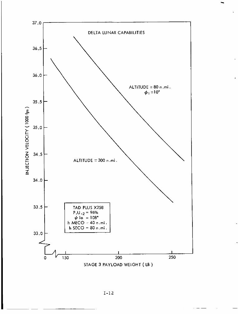
37.0
36.5
36.0
35.5 - B Lc
0 8
E
Y
u,
- - 35.0
8 J
g 34.5 - 6
7
Z - 34 .O
33.5
33 .c
DELTA LUNAR CAPABILITIES
TAD PLUS X258 P.U .2 = 96% 1,5 io = 108"
h MECO = 40 n.mi . h SECO = 80 n . m i .
I I I 150 200 25 0
STAGE 3 PAYLOAD WEIGHT ( LB )
1-12
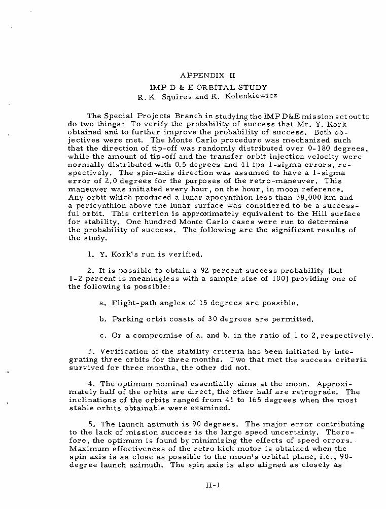
APPENDIX I1
IMP D & E ORBITAL STUDY R. K. Squires and R. Kolenkiewicz
The Special Projects Branch in studying the IMP D&E mission se t out to do two things: To verify the probability of success that Mr. Y. Kork obtained and to fur ther improve the probability of success . Both ob- jectives were met. that the direction of tip-off was randomly distributed over 0- 180 degrees , while the amount of tip-off and the t ransfer orbit injection velocity were normally distributed with 0.5 degrees and 41 fps 1-sigma e r r o r s , r e - spectively. The spin-axis direction was assumed to have a 1-sigma e r r o r of 2.0 degrees for the purposes of the ret ro-maneuver . This maneuver was initiated every hour, on the hour , in moon reference. Any orbi t which produced a lunar apocynthion l e s s than 38,000 k m and a pericynthion above the lunar surface was considered to be a success- ful orbit. This c r i te r ion is approximately equivalent to the Hill surface f o r stability. One hundred Monte Carlo cases were run to determine the probability of success . The following a r e the significant resu l t s of the study.
The Monte Carlo procedure was mechanized such
1. Y. Kork's run is verified.
2. It is possible to obtain a 92 percent success probability (but 1-2 percent is meaningless with a sample s ize of 100) providing one of the following i s possible:
a. Flight-path angles of 15 degrees a r e possible.
b. Parking orbi t coasts of 30 degrees a r e permitted.
c. Or a compromise of a. and b. in the rat io of 1 to 2,respectively.
3 . Verification of the stability c r i t e r i a has been initiated by inte- grating three orbits for th ree months. survived for th ree months, the other did not.
Two that me t the success c r i t e r i a
4. The optimum nominal essentially a ims at the moon. Approxi- mate ly half of the orbi ts a r e direct , the other half a r e re t rograde. inclinations of the orb i t s ranged f rom 41 to 165 degrees when the mos t s table orb i t s obtainable were examined.
The
5. The launch azimuth i s 90 degrees. The major e r r o r contributing to the lack of mission success is the la rge speed uncertainty. There- f o r e , the optimum is found by minimizing the effects of speed e r r o r s . Maximum effectiveness of the r e t r o kick motor is obtained when the spin axis is as close a s possible to the moon's orbital plane, i.e., 90- deg ree launch azimuth. The spin axis is also aligned as closely as
11- 1

possible to the vehicle velocity vector with respec t to the moon. is accomplished through the high flight-path angle o r the parking orb i t , o r both. t ransfer -orbit injection speed have equal probability of success. character is t ics of the nominal a r e given in F igures 1, 2 , and 3 and Table I.
This
The flight t ime is such that plus and minus 3-sigma cases in The
To insist on a low flight-path angle and no parking orbit reduces the success probability to about 50 percent.
The stability checks were made for the following orb i t s :
I. r p = 31,710km
r a = 84,008 k m
w = -149" with respec t to moon's orb i t plane
Period = 3 4 7 h r s .
Stay t ime in moon reference = 6 7 h r s .
11. rp = 3091 km
r a = 3442 km
w = 117."
Period = 4.65 h r s .
Lifetime exceeds 3 months.
111. rp = 3994
r a = 11,763
w = 2.6"
Period = 17.4 hrs.
I Lifetime exceeds 3 months.
11-2

loo> 90
80
70 Z 0
Z 4 60- n
0
5 50-
- 5
w w
i - I
G B U
40- - I-
1 3 V Z -
30
20
-
-
-
-
-
CHARACTERISTICS OF THE IMPROVED NOMINAL TRAJECTORY BEFORE RETRO KICK MOTOR IMPULSE
\. \ PERlCYyTHlON ( 1 0 3 x Km)
APOCYNTHION ( 1 0 3 x K m ) 10 -
76
*--.
66 68 70 72 74 0
.o
. 9
8
7
6
t u
5 t c E
- w
4
3
2
1
1
TIME OF IMPULSE
11-3

-90
h Ln W W w
-60 v
Ln - X Q Z h Ln
6 W -1
(3 Z Q Z 0 Q > - c
w -1 W
w* -3( -1
(3 Z Q I c 2 I- I (3 - -I LL
- 1
FLIGHT PATH ANGLE 17
S P I N AXIS VELOCITY
CHARACTERISTICS OF THE IMPROVED NOMINAL TRAJECTORY BEFORE RETRO KICK MOTOR IMPULSE
?O
60
h
Ln W W w
2
c 3
n v
v
W > c” X Q
I I I I I I 1-10 64 66 68 70 72 74 76
TIME OF IMPULSE (HOURS)
II-4

100
80
A
5
Z 60 0 0 5 5
Y v
B
2 n -I 40 5 n 5
U
v, -
20
0
CHARACTERISTICS OF THE IMPROVED NOMINAL TRAJECTORY BEFORE
RETRO KICK MOTOR IMPULSE
'\ VELOCITY ( M O O N REF)
RADIAL DISTANCE FROM MOON ' 0 ,
I 1 I I I I
TIME OF IMPULSE (HOURS)
2.4
2.2
2.0
1.8
n
s rn
1.6 2 Y v
n
LL w w
1.4 6 0 5 v
E U 1.2 0
5 -1
1 .o
.8
.6
.4 )
II-5

- r- co Ln 0:
9 r- Ln d d !'; r- L n o
N d d
2 z u 0 4 d 4 u w
0 ; 2 0 0 d
d 0 h [I]
2 a d 0 pc 2 n H
w d 0 z u z 4 h 0 cn 2 a i?
d w b 0 4 p: 4 z u
m m d
r-' N
c l . h
! 9 0 N
Ln
9 0
d
d
9 N 0 co
m d d
N
co r- m 9
co r- co
9
- N
-
Ln
11-6

- 0 co Lo N b I
- 6 4
9 m
- 9 b
N ? d
- 0 a
In 4
- N 0
0 F
?
- 0 N 6 m I'- I
0 m
m 9
b b m s'
a N 9
s' d
0 9 m 9'
d
9 N co m
r- m 9 m
m a3 * m
* 0 * N
-
2
N
0 00
d a 0
m d
d
0 0 a3 Lo m
m In m N
r- N 0 m
_.
N b
N * N N
m c-
n e- b 9
Y
n cc. 9 a Y
0 b
m co 0 b
co b
a d
0 N
6 d
N N
9 N
d
N
11-7

- o\ Ln N
N N
_.
N N
0 cr)
.?
- o\ cr) o\
.-I
t- I
- d
N
0 w c'!
- 0 Ln
cr) r\l
d
- o\ Ln co 0 d
- o\ * co N
l-4
co 9 P
9
o\ N 0
a5 d
0 co d
l-4 d
0 0 N 4 d
co Ln cr)
d * 9 Ln
N 4
co d
d
d
0 d
d
0 Ln d
4 d
d
s'
Ln * co cd
9 r- N
0 4 l-4
N w 9
rr) In 4
0 m Ln
co N d
Ln 0 co N 9
r- 0 N
9 N l-4
co 2 m cr) d
Ln 9 Ln
cr) d d
0 N Ln
N 9 d
co * * 0 N d
N o\ r-
9 l-4
l-4
m 2 d Ln d
Ln
co
r-
d
d .rl
r- o\ co 9
a3 r- 9 w
In co Ln 9
Ln 0 rr) Q
Ln N Ln 9
o\ o\ 9 9
Ln co 9 l-4
o\ 0 * Ln
Ln cr) 0 9
4
m o\ dr
N L n
Ln
l-4
N 9 Ln
r- N r- o\ cr)
-
co M l-4 d
d
Q)
-+ m 9 rl
a3 0 co w A
9 cr)
rr) d
d
o\ N o\ 0 d
b 9
cr) l-4
d
0 co o\
N co 9 o\
0 0 co d
o\ w 0 rr)
9 m 0 N
-
2
0 9
N l-4
-
N t-
dr In N N
d
Ln a d
co o\ rc d
Ln r- Ln r-
Ln t-
i+ * c,
Ln
r- t-' r-
r- 0 r-
Ln P
N r-
co t-
z J d
o\ N
N cc1
Q m r- cr)
o\ m
0 * d * N *
11-8

- 9 9 N
m IC
d
9 m r-'
m 0 m m N
I
-
9 m m
N 4
IC co
m 9
d:
N m m 4
N N 0 m I
d
IC 9
co u-i
0 IC 9
IC m
m m IC
ai
* N
9 m
d
d
9 N IC m
IC r- 9 N N
m N 9 N
0 * 0 m A
N 9 0 N
m m N N
d 4
IC N
9 9 m 0 d
m N
m F
h
c. In co Y
m 9 IC
m
i+ e c, co
IC d
IC m 9
N IC
-
0 m m d.c
m e
11-9

- d
N N
od I
- co 0 0
N N
- F N d
d
N
- 0 rrl D
N d
M m co N &
0 N m
0 N
d
-
* m co co d d
N N * d d
-
m co m
co d
co 9 0
r-'
9 IC * 9 d
d
m * s'
d
0 b
m od d
N
m m
d
-
m * * 2
9 co * m
-
* m 9
d
N m m m
-
N F m 9
m m m N 4
F co IC co m
0 m IC d
n
c. 9 co Y
m
IC 9
m IC
11-10

- co 9 6 0 4
4 6 0
F d
tc
F
I- I
d
d
4
m
co
4
4
d
6 9 F
d
4 co m
6 F
m d
d
N 0 co N
Y - d
N 6 m d
N m
I- N
d
6
6
N P i
N 0 m
N 4 -
m tc 9
4 d
d
0 co 9 4 d
m 03 4
m d
m N 6 I- m d
4
d N
4 9
d
d
6
N m d
0 d d
0 N d
co 6 m
Q d
9 Ln 0
m d
d
N 9 9 0 0 d
N 9 I- 4
N 9 m N m d
F N I- 4
.d
m N 0 Q
tc 9 F d
0 9 6 m
-
0 9 rn N l-l
4 N Ln 4
I- 0 9 9 d
co 0 m m
d
00
9 4
N
4 4
d
m m 0 fc N
0 6 4 0 d
9 0 co 9
9 6 m d d
m 0
4 d
Ln 4 m cr) d
co Ln 2 d
-
e 6 F N
co 9 4 m
-
9 N 4 N
m co co I- N
2 9 6 N
co 0 9 m
0 co In Ln
d
F
m 6 a3 6
4 co
m 0 9 0 d
h
e. co 9
Y
N 9 N 9
0 F
9 9
N d
In F
d
F 6 N
co I-
In
9 I-
- N co
6 Q
- m co
F co 00 co 6 co 0 6
N 6
m m
11- 11

.rl
Ln 0 m
N 0: d
co In 0 Q
In Ln
m In
d
-
0 N In * d
c
c. r- 9
-
\D m
- cr) \D r-
I' I
0:
r- Q * In
I' m co N d
0 a3 t- m
11-12

OPTIONAL FORM NO. 10 5010-104
UNITED STATES GOVERNMENT
Memorandum TO : FILE
FROM : W. M. Kaula
APPENDIX 111
DATE: December 13, 1963
SUBJECT: Calculation of Perturbations of Lunar Orbi te rs
1. Summary. Three types of calculations were ca r r i ed out. Their
principal charac te r i s t ics and results:
a . Lifetimes for IMPS D 81 E. Runge-Kutta integration of the La-
grangian planetary equations was ca r r i ed out for the 100 orb i t s of a Monte
Carlo study.
is the ear th effect which is long-periodic with respect to both the lunar
satell i te and the earth-moon orbit.
67, 120 days; 61, 160 days; 56, 200 days; 48, 300 days; and 43, 400 days.
Fo r these orbi ts , the important par t of the disturbing function
92 orbi t s survived 40 days; 75, 80 days;
b. Lifetimes for Langley Lunar Orbi te rs . The same calculation was
ca r r i ed out for lunar satell i tes having a 20-n. mi. per icenter height and a
750-n. mi. apocenter height. For these orb i t s , the important par t of the
disturbing function is the J3 t e r m of the moon's gravity field, i f it has a
magnitude implying the same s t r e s s e s in the moon as does the ea r th ' s J3
in the earth. Of 1 2 orb i t s with varying inclination and per icenter argument,
11 survived 20 days; 7 , 40 days; 5, 100 days; and 3, 400 days.
c. Per turbat ions bv variations in the moon's gravitational field. Linear
perturbations of the Lagrangian planetary equations were calculated for a
typical variety of IMP D & E orbital specifications. The variations in the
lunar field were assumed to be of an order-of-magnitude implying the same
s t r e s s e s in the moon a s do t e rms of the same wave-length in the ea r th ' s
field. Assuming a s a cr i ter ion of success that the anticipated perturbations
due to a t l eas t two t e s se ra l harmonic t e r m s exceed *500 m e t e r s , the semi-
major axis for re t rograde orbits should be l e s s than about 4 lunar radi i ,
for direct o rb i t s , 6 lunar radii. Lowering the cr i ter ion to * l o 0 m e t e r s , it
becomes about 7 lunar radi i for re t rograde orbi ts and 10 lunar rad i i for
d i rec t o r bits . 111- 1

2. Lifetime Calculations. These calculations were ca r r i ed out by
standard Runge-Kutta numerical integration ( see Appendix) of the stan-
dard Lagrangian planetary equations ( see Appendix) with a disturbing
function which can be summarized as:
RE is the third-body disturbing function of the earth. RE, is the
long-period par t , and RES i s the short-period part: Le., containing
monthly, semi-monthly, etc., t e rms . The subscript 4 pertains to the
degree in the expansion of the disturbing function in Legendre polyno-
mials ; the subscript j , to the eccentricity function in the coefficient
and the short-period par t of the argument of each t e r m of the develop-
ment. RS2, is the third-body disturbing function of the sun, which is
ca r r i ed only to include the second-degree Legendre polynomial and
which neglects the effect of eccentricity of the ear th ' s orbi t around the
is the secular effect of the moon's oblateness, and R,,,,, sun* RM2 0 1 0
is the semi-monthly effect of the moonls equatorial ellipticity.
i s the long-period effect of a third zonal harmonic in the moonls gravi-
tational field: the 2 appears because the one t e r m 2RM3,,,
place of the two equal t e r m s RM3021 t RM301( - . The mathe-
mat ical definition of R is given in the Appendix, and the derivations in
references (1) and (2).
2RM3,, ,
is used in
Al l the parameters in R a r e known except J3, the third-degree zonal
harmonic coefficient, which is completely unknown.
because, i f the J3 of the moon is la rge enough to entail s t r e s s e s in the
moon comparable to those implied in the ear th by i t s J3, then the perigee
heights will have perturbations la rge enough to greatly affect the l i fe-
t imes of closely approaching lunar orbi ters .
coefficients a r e the same magnitude a s potential t e r m coefficients in a sys tem of units where the gravita"tiona1 constant k , the mass M, and the
radius a, of the planet a r e a l l unity. Since k , dimension L3M-' T-2,
It is included
The J,, o r cnm and Snm,
I11 - 2

i s the same everywhere, the time unit mus t scale a s L312 M - ' 1 2 . Hence
s t r e s s , dimension ML-'
must be M - 2 L4 t imes as great to imply comparable s t resses . F o r the
moon compared to the earth, the rat io M-2L4
about 36.3 , so a reasonable order-of-magnitude for the lunar J, i s
f 3 6 . 3 x 2.58 x = k9 .3 x
T - 2 , must scale a s M2L-4 , or coefficients J,
is .0123-2 x .272S4 or
Numerical values of other pa rame te r s used a r e given in Table 111-1.
Options possible in each lifetime run a re :
(1) The maximum degree 4 of the Legendre polynomial for the
earth 's disturbing function, RE, o r (REL t RES).
( 2 ) Whether or not t e rms short-period with respect to the orbit of the ear th around the moon, RE, + R Y 2 2 1 0 , a r e to be taken into account.
(3 ) If short-period t e rms a r e to be included, the maximum
power of the eccentricity of the ear th ' s orbit about the moon to be taken
into account, which determines the range of subscript j . (4) Whether or not solar perturbations, arising f rom R S Z O ,
a r e to be taken into account.
(5) Whether o r not a hypothetical J, effect, 2R,,021, i s to be
included.
(6 ) The integration interval.
(7) The printout interval.
(8) Whether longitudes a r e measured f rom the vernal equinox
o r the earth-moon line a t a particular epoch.
(9) Whether inclinations a r e measured f rom the earth-moon
orbi t plane o r the lunar equatorial plane.
fo rmer option o r of RE in the latter option have not been made in the
program, since the inclination is smal l and the choice of reference plane
depends on which par t of R i s m o r e important.
The corrections of RM in the
111- 3

The program was tes ted against the Pines-Wolf Encke integration
sys tem "ITEM" for an orbi t with elements a = 1.8795 lunar radi i ;
e = .OS37 ; and i = 127.2" . Results of the comparison a r e given in
Table 111-2.
The principal calculation made on the 100 Monte Carlo orb i t s
generated by Special Pro jec ts Branch was of l ifetimes up to 400 days
with a disturbing function (REL2 t RMZOlO) long-periodic with respec t
to the earth-moon orbit , and integration interval of 20 days.
a r e given in Table 111-3 and Figures 111-1 and 111-2. al ternat ives were tes tedon a few character is t ic orbi ts :
The resu l t s
The following
( 1 ) Shorter integration intervals with the same disturbing func- tion gave the same resu l t s a s the 20-day interval. An interval longer
than 20 days was not tested, since it took only 11 minutes to compute
all 100 lifetimes.
(2) Inclusion of t e r m s short-periodic with respect to the ear th- moon orbi t , arising f rom RE,,, t RMZZIO y together with the necessary
shortening of the integration interval, resul ted in moderate shortening
of some lifetimes l e s s than 120 days, and extreme shortening in only
one case , as given in the 7th column of Table 111-3.
( 3 ) Inclusion of RM3021 , R,,, , o r RE,, perturbations had
no effect on lifetimes.
(4) Varying of the t ime of injection into orbi t around the moon
by 1/2 hour had significant effect on the lifetime only for a few t ra jec-
t o r i e s headed directly toward the moon, a s given in the l a s t two columns
of Table 111-3.
The lifetime calculation was also made for orbi ts with charac te r i s t ics
approximating those of the Langley lunar o rb i t e r , using a long-periodic
disturbing function RE,, + 2RM3,,, incorporating the "equal-s t ress"
J, coefficient of -9 .3 x 10-5.
cen ter , a s given in Table 111-4.
It was a l so made for orb i t s of higher per i -
I11 - 4

For a zero J, , al l these orbits have indefinite l ifetimes. Fo r a
J, of t9.3 x
center argument differing by 180'. Since the sign a s well a s the mag-
nitude of J, i s unknown a t present, Table 111-4 indicates that for a
pericenter height of 20 nautical miles , even the optimum choice of
pericenter argument a t injection chances a lifetime l e s s than 200 days.
In the first approximation, the lifetime depends on how close is the
orbi ter at injection to the minimum of an oscillation of the per icenter
height with the same period a s the pericenter argument. The magnitude
of the pericenter height oscillations is due not only to the large 5, , but
a l so to the long period of the pericenter revolution: about 400 to 500 days.
, the l ifetime is that given in Table 111-4 for a per i -
3. Calculation of Perturbations by Variations of the Lunar Gravitational
Field. If fully normalized spherical harmonics a r e used-i.e., func-
tions such that the integral of the square over the unit sphere is 477- then the o rde r of magnitude of potential coefficients e,,, Snm of the
ear th ' s gravitational field follows roughly a rule of f 6 . X 10'6/n2.
-
If the "equal-stress" assumption i s made, then the order-of-magni-
tude of potential coefficients of the moon's gravitational field will be
roughly *:36 x 6 x 10'6/n2 = 2 X 10'4/n2.
The perturbations caused by such coefficients were calculated by
using the expression of the spherical .harmonic potential in Keplerian
elements ( see Appendix) a s a disturbing function in the Lagrangian
planetary equations and integrating them, assuming that on the right-
hand side of the equations the semi-major axis, eccentricity, and in-
clination remain constant, while the mean anomaly, argument of per i -
center , longitude of the node, and lunar s idereal t ime have a constant
r a t e of change with respect to time. The calculation was c a r r i e d out for
spherical harmonics up to (n,m) = (4 ,4 ) for 10 orb i t s distributed over
the variety of 100 orbi ts obtained in the IMP D & E Monte Carlo study.
I11 - 5

The results a r e summarized in Table 111-5. It appears that mos t
IMP D & E orbits will be adequate to obtain some measu re of the J,
zonal harmonic coefficient, which would be of great value in planning
subsequent closer orbits. To obtain a measu re of the t e s s e r a l harmonics
in the lunar field, which cause perturbations of monthly, semi-monthly,
etc. period, is more difficult. If an amplitude of f500 m e t e r s in these
perturbations due to a t l eas t two coefficients i s considered adequate for
determination of these harmonics , then about 50 percent of the IMP orbi ts a r e successful. These orbi ts have semi-major axes which a r e
roughly l e s s than 4 lunar radi i for re t rograde orbi ts and 6 lunar radi i for
direct orbits. If an amplitude of * lo0 m e t e r s is considered adequate,
then about 75 percent a r e successful. These orbi ts have semi-major
axes which a r e roughly l e s s than 7 lunar radi i for re t rograde orbits and
10 lunar radi i for direct orbits.
Hence IMP D & E will a lmost definitely be of value in determining
the J, zonal harmonic, and will have a fair chance of determining t e s s e r a l
harmonics which a r e of equally great geophysical interest .
References
(1) Kaula, W. M. (1961) Geophys. J. 5, 104.
(2) Kaula, W. M. (1962) Astron. J. 67, 300. .
(3) Kozai, Y. (1963) Publ. Astron. SOC. Japan 15, 301.
111 - 6

TABLE III-1
Numerical Values of Parameters Used in Lunar Orbi ter Calculations
Par ame t e r s Value ( A l l angles i n radians)
Moon Radius Oblateness, 32 Equatorial e l l i p t i c i t y , J 2 ,
Eart.h's orbi t with respect t o moon Earth/moon mass r a t io Semi major axis i n lunar radii Eccentricity Mean inclination to lunar equator Longitude of node, 1959 Jan 0.0 Mean motion of node per day Argument of pericenter, 1959 Jan 0.0 Mean motion of pericenter per day Mean anomaly, 1959 Jan 0.0 Anomalistic mean motion per day
Sun ' s o rb i t w i t h respect t o moon Sun/moon mass r a t io Semi-major axis i n l inar r a d i i Eccentricity Inclination Longitude, 1959 Jan 0.0 Mean motion per day
1738.0 Km .000220 .000024
81.3 221.17
05 49 .1164
0.31602
0.2933%8 +.0028676 5.3599926 +. 228027 1
- ,0009242
2.7 10' 8.58 x loA . 000 . 000 4.. 8767 +.0172028
III- 7

TABLE 111-2
Comparison of Integrations for Eccentricity
Days
I 0 2 4 6 8 10 20 40 60 80 100
I n i t i a l e l e m e n t s a = 1.8795, e = .0537, i = 127.2'
Runge-Ku t t a I n t e g r a t i o n Pines-Wolf "ITEM" of Lagrang ian E q u a t i o n s Program, Encke- type
.05370
.05368
.05385
. 0 5 a 1
.05396
.05361
.05297
.0507 1
.0496 1
.04778 ,04665
05375 05374
.05378
.054lO
.051p1
.05384
.05281
.05067
.04949
.04788 . olt642
111-8

0 0 0 ?$;9
. . . o \ D
. . .
8 x 2 o m
8 8 3 %
0 0 0 0 3 0 5 9 3
. . . \D
. . . c u c u c u
c u o \ p c * A t - d d c u . . G nco
111-9

a 0 2
8 -5
f v
Fi v) v)
cd & 0 t-
o\ w cu G
cu v) 3 cu
cu m M =+
cu Fi m \D cu
s f cu
e- M n M
cu Fi 3 cu
cu 3 t- t-
d v ) Fv) M t - M M . .
0 v) In d
Fi
2 cu

0
0
v
111- 11

0
0
9
P l n E - - \ o r l t - c u d C h l n d c u . . . . . .
Inn . .
* I n . . . In In lnln f \o
.A . . d c u
. . cu d o i d ; . . d d d d
c u c u M c u 9'4
M r l \ 9 " % . . . - . . . . . . . . . . .
8% . . c u m cu
. . r c ; l I i r l c u 6 ; ;
rl
. . . . . r i i c u c u cu
m o r l c u l n \ o \ o \ o
r l c u E - E -
0 R
111- 12


TABLE 111-4
Lifetime Calculations for Langley Lunar Orbi ter and Modifications Thereof Assuming Lunar 53 = -.000093
Injection a t 1965 June 12
Pericenter Apocenter Semi-major Eccen- Inclination Argument of Lifetime Height Height Axis i n t r ic i ty t o Lunar Pericenter Days n. m i . n. m i . Lunar Ram Equator
20
20
20
20
20
20
20
20
20
20
20
20
120
120
120
120
120
120
120
120
120
120
120
120
250
750 750 750 750 750 750 750 750 750 750 750 750 750 750 750 750 750 750 750 750 750 750 750 750
1000
1.406 1.406 1.406 1.406 1.406 1.406 1.406 1.406 1.406 1.406 1.406 1.406 1.447 1.447 1.447 1.447 1.447 1.447 1.447 1.447 1.447 1.447 1.447 1.447 1 659
* 2734 9 2734
2734 - 2734 2734 2734 2734 2734 2734 2734 ' 2734 2367 2367 2367 2367
.2367 2367 2367
* 2367 2367
* 2367 ' 2367 2367
9 2367
,2734
20°
20°
20°
20°
20°
20°
30° 30° 30° 30' 30' 30° 20°
20'
20°
20°
m0 20'
30°
30° 30' 30° 30° 30°
20°& 30'
O0
120°
60'
180' 240' 3 0 0 O
0'
120°
60'
180' 240' 300'
0'
120°
60'
180' 240' 300'
O0
120°
60'
180' 240' 3m0 A l l
111- 14

4 0 0 In 0 -P
0 0 rl
ti 0 0 0 rl
0 4J
8 In
i 0 0 0 rl A
M f
= t M . r f M
i
0"
0 cui
rli 2 d 0-
f
= t M
M M
M M cui a-rl cu c u f
c u p c n r l cha ocu . .
% S o r ? M A . .
ncu m u 3
r l c u ?-?
f f
f cu A
u? i
rl 4-
rn M
M
*
cu"
0 A
rl M
rn cu cu
i
d .I
0 f a3 rl
v) cu 3 A
k ch In
cu
cu A
f =I-
M 4-
M M cu M
M
i
i
i
Ai
cu A
f
M M
M
2
cui
i
rl M
0 f
2 cu rl
v)
v)
In In In n
A cu ln cu
3i 4-
0 cu v)
n
rl =I-
M M
M
0
i
2 2
0 3
M cu cu
d i
ch 0 f
rl
ch P 0 v)
t- cn 0
v)
rl M
c u c u c u c u
0 0 n n
c u c u 3 r l r l l n . . - 0
rl
111- 1 5

c
Z
Q Z
U Z
Q I-
- -I
-
0 0 h- 7
0 0 9- 7
0 0 m- - 0 0 d- 7
0 0 m- - 0 g- - 8- 7
0 0- 0 7
0 0- 0.
0 0- 03
0 0 h-
0 0- 9
0 0- m
0 0- d
0 cv d -0
0
0 0
0.
L o w > ;
111- 16

C T
C c
0 0 9
0 9 m
0 c*l m
0 a3 (u
0
0 0 (u
0 9 .-
8 -
0 a3
0 -4.
0
-D 0 > 0
c 0
0 In
Y
.-
In al E
I cy
9NIAIANlS Sll9tlO d o lN33113d
111- 1 7

APPENDIX
1. Lagrangian Equations of Motion
Osculating Keplerian elements
s, = M: mean anomaly
% = a: semi-major axis
s e : eccentricity
S, i: inclination
S, w: argument of perigee
S, = R:
3
longitude of node n = S;3/2
1 / 2 = (1 - 5;)
D = nSi7 sin S,
2 aR s2 =-. nS, - as,
111- 18

2. Disturbing Function:
kM = 1 for the moon, and the unit of length is the moon's radius
thruout.
a.
where m E is the mass of the earth in lunar masses ;
quantities subscripted by E pertain to the ear th 's orbi t with respec t
to the moon;
so,,, is the Kronecker delta;
m , p , h a r e all summed from 0 to 4 ;
C .
( e ) cos [( 2-2p)w t m a - ( 2 - 2 h ) A,] , X H & p ( 2 p - 4 ) ,
111- 19
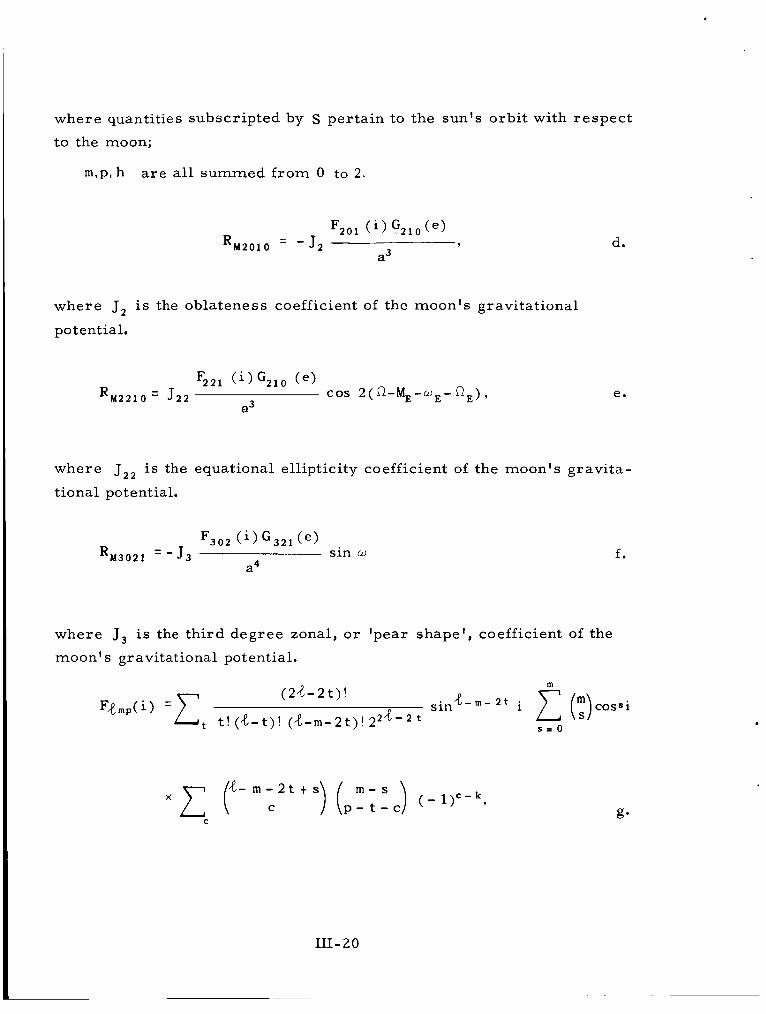
where quantities subscripted by S pertain to the sun 's orbi t with respec t
to the moon;
m,p, h a r e a l l summed f rom 0 to 2.
where J 2 is the oblateness coefficient of the moon's gravitational
potential.
d.
e.
where J22 i s the equational ellipticity coefficient of the moon's gravita-
tional potential.
where J 3 is the third degree zonal, or 'pear shape' , coefficient of the
moon's gravitational potential.
f .
x x r - m - 2 t t s ) ( p r - s ) ( - l y - k , C t - c
C
111-20

where k is the integer par t of (d-m)/2;
t is summed f rom 0 to the l e s se r of p or k; and
c is summed over all values making the binomial coefficients non-
zero.
where
d
zero.
s summed over all values ma__,,ig the binomial coefficients non-
h'-1 2d +4-2 h '
2 d t 4 - 2 h ' j. 1 4-1 '4h(2h-4> (e) = (1 - e2) 4-1/2 d= 0 ( 2 d + 4 - 2h') ( d ) (f)
where h' = h, hL 4/2,
h' = 4 - h , h 2 4/2.
For j # 2 h - 4 , k.
q = k t j', j ' > 0, q = k, j ' < 0 ;
111-21

q = k, j ' > 0 ; q = k - j ' , j ' < 0 ;
h' i s defined a s in 2j above.
'max
4. R = [L$t , E + R S 2 0 t R M 2 0 1 0 t R M 2 2 1 0 2RM3021
.e= 0 l = - J m a x
aR - aR aR - aR aR - aR _ _ - - _ - - _ - as, a ~ ' as2 aa' as, ae'
3. Runge-Kutta Integration
Si [S,. tl Si (S1, S2, S,, S4, S,, S,, t ) , f rom the Lagrangian
equations in Sec. 1.
wi = si [Sj( t ) , tl A t
Xi = si [S,(t) t W j / 2 , t t W 2 1 A t
z i = si [S,(t) t y,, t t At1 A t
111-22

4. Expression of Spherical Harmonic Potential in Keplenian Elements.
where ae is equational radius; v , +, X a r e spherical polar coordinates;
and P4, ( s in $) is the Legendre Associated Polynomial; t ransforms to;
where a, e, i , M, w , n a r e the Keplerian elements, 8 is the "lunar s iderea l
time", and F,pmp ( i ) , G4,, ( e ) Appendix. The lunar s idereal time 0 is most conveniently taken a s the
mean longitude of the ear th , which makes the reference meridian for
lunar longitudes coincide with the mean direction of the earth.
a r e a s defined in Secs. 2h, 2k of the
III-23

APPENDIX IV THE ANCHORED IMP SCIENTIFIC MISSION
D r . N. Ness
ABSTRACT :
The p r imary goal of the anchored IMP satell i te w i l l be to investigate interplanetary magnetic fields, so la r plasma fluxes, so la r and galactic cosmic r ays , and interplanetary dust distributions in the vicinity of the moon. A principal problem in cosmic electrodynamics is the interaction of a moving magnetized plasma and a solid object. This phenomenon can be definitively studied with a n orbiting anchored IMP satell i te whereby the interaction of the solar wind and the moon can be studied without the complicating effects of a planetary magnetic field. High energy par t ic le detectors and ionization chambers a r e included in the ins t ru- ment reper to i re as well a s a cosmic dust detector and a t r iaxial flux- gat e magnetometer.
with magnetometers, plasma and par t ic le detectors on the anchored IMP and other spacecraf t will provide invaluable data about the propagation of so la r t ransient disturbances in interplanetary space. In addition, the anchoring of the satell i te in the lunar gravitational field will allow the magneto-hydrodynamic wake of the ear th in the interplanetary medium t o be studied at lunar distances.
The possibility of performing simultaneous measurements i n space
A second major objective of the anchored IMP mission will be a This will provide cr i t ical detailed analysis of its orbital dynamics.
information on the lunar gravitational field and pe rmi t the investigation of the mass distribution in the moon. mination of the earth-moon mass rat io and the figure of the moon. Accurate knowledge of the lunar gravitational field is important in determining the bulk properties of the lunar body, and the development of m o r e specific models of the lunar inter ior . Finally, detailed know- ledge of the lunar gravitational field will be of importance in future lunar missions requiring accurate t ra jec tory and orbi ta l maneuvers .
It will a l so improve the de t e r -
Introduction
Direct measurements of the physical propert ies and dynamical charac te r i s t ics of the interplanetary medium have been performed in recent yea r s through the utilization of deep space probes. The mag- netic field of the ear th has a s t rong effect on its immediate space en- vironment and thereby drastically modifies cer ta in of the charac te r i s t ics
Satell i tes which orbi t the ear th a r e in general thus unable to sample the undisturbed interplanetary medium.
- of the interplanetary medium.
IV -1

The pr imary mission of the IMP (Interplanetary Monitoring P la t - fo rm) program has been to develop an ear th satell i te with an orbital eccentricity sufficiently la rge so that detailed measurements of the interplanetary medium in the vicinity of the ear th a r e possible. The IMP orbit as planned offers a unique opportunity to investigate the in- terplanetary medium and a l so the transit ion region between i t s unper- turbed status and the magnetosphere of the ear th . Many t ransient geo- physical phenomena associated with so la r activity a r e a direct resul t of the interaction of the ea r th ' s magnetic field, i t s atmosphere, and the so la r corpuscular fluxe s .
In continuing the exploration of the interplanetary medium and the interaction effects associated with so la r particle fluxes and planetary objects, the next logical object for investigation is the closest neighbor of the ear th , its own satellite, the moon. the lunar gravitational field fo r "anchoring" an orbiting satell i te in the interplanetary medium but yet in close proximity to the ea r th was r e c - ognized several yea r s ago. to place a 390-pound scientific satell i te into a close orbit around the moon. of the lunar environment and included magnetometers, radiation senso r s and micrometeori te detectors. was not successful with al l launches ending in destruction of the vehicle.
The possibility of utilizing
The mission of the Able V program1 was
The experiment reper to i re was designed to investigate aspects
Unfortunately this satell i te program
Since that t ime the investigation of the moon, its surface and its body properties, has become an increasingly important portion of the space research program. dium in the vicinity of the moon remains to be explored and as yet there a r e insufficient plans for adequate investigation of these phenomena, particularly on a monitoring basis . the technical design of the IMP spacecraft have suggested that the basic spacecraft structure and te lemetry system is appropriate for additional scientific missions. a lunar orbit with the pr imary mission being the investigation of the particle and magnetic field environments in the vicinity of the moon, as was the original intent of the Able V program.
Anchored IMP Mission
The investigation of the interplanetary m e -
The developments associated with
This led to a consideration of placing an IMP into
The technical capability of the IMP satell i te and its associated launch vehicle is such that a relatively close lunar orbit is possible with the addition of a 4th stage injection motor. It is proposed that a slightly modified IMP satell i te weighing approximately 11 0 pounds be placed into a lunar orbit during the t ime interval June to December, 1965 so as to coincide with the IQSY (International Year of the Quiet Sun).
The satellite will monitor the interplanetary medium and lunar I environment throughout a major portion of its orbit , a s in the case of
IV-2

the standard IMP. The transition region between the interplanetary medium undisturbed by the planetary object and that region of space in i t s immediate proximity where its presence dominates the physical phenomena will a l so be investigated.
A pr imary goal of the anchored IMP mission w i l l be to investigate interplanetary magnetic fields, solar p lasma fluxes, and sola,r and galactic cosmic rays in the vicinity of the moon. A principal problem in cosmic magneto-hydrodynamics is the interaction of a moving mag- netized plasma such as the solar wind, and a solid object such a s the moon. This phenomenon can be definitively studied with an anchored I M P spacecraft . High-energy particle detectors and ionization chambers a r e included in the instrument repertoire. The possibility of performing simultaneous measurements in space with magnetometers, plasma and cosmic ray detectors on the anchored IMP and other spacecraft , possi- bly a standard IMP, w i l l provide invaluable data about the propagation of so la r t ransient disturbances in interplanetary space.
The second major objective will be a detailed analysis of the orbital dynamics of the lunar orbiter. This will provide cr i t ical information on the lunar gravitational field and permi t the investigation of the mass distribution in the moon. It will a l so improve the determination of the earth-moon mass ratio. The figure of the moon derived f rom perturba- tions of i t s own orbit suggest a concentration of mass outwards r a the r than into the moon's interior. Accurate knowledge of the lunar gravi ta- tional field i s extremely important in determining the bulk propert ies of the lunar body, and development of m o r e specific models of the lunar in- te r ior . In o rde r t o c a r r y out the detailed studies of the orbital dynamics an appropriate range and range rate sys tem is included in the experiment repre to i re t o provide sufficiently accurate data on the position of the spacecraft for such orbital analyses. tional field will be of great value i n the future lunar missions requiring accurate t ra jectory maneuvers.
Knowledge of the lunar gravita-
At the present time the nominal lunar orbit pa rame te r s corresponding to the p r imary constraints of the I M P spacecraft and launch vehicle a r e :
Per icynthion. . . . . . . . . . . 500 to 1500 ki lometers Apocynthion . . . . . . . . . . . 3000 to 10,000 ki lometers Inclination . . . . . . . . . . . . Highest possible up t o 75" Lifet ime. . . . . . . . . . . . . . At leas t 6 months
Orbital character is t ics of the anchored IMP a r e such that for most of each orbital period, data will be t ransmit ted f rom the satell i te which can be received bv te lemetry stations located on the earth. remainder of the t ime the satellite will be eclipsed by the moon with respec t to radio reception by the earth. additional information about the electron densit ies in the vicinity of the moon.
During the
This eclipsing may yield
IV-3

An important aspect of the anchored IMP w i l l be the possibility of measuring simultaneously s imilar phenomena in space. tion of spatial and temporal variations in the s t ructure of the in te r - planetary medium and the detailed description of the propagation of so la r transient phenomena require simultaneous measurements at points separated f rom eachother in the vicinity of the ear th . o redIMP provides f o r such measurements Nith identicalinstrumentation and hence provides a unique opportunity tor such studies. lation of separate experiment 's data on the same spacecraf t as well a s of s imi la r o r identical experiments on separate spacecraft allows for adequate experimental investigation of complex solar t e r r e s t r i a l relation ships .
The sepa ra -
The anch-
'l'he c o r r e -
Detailed investigations of the interplanetary dust distribution in the vicinity of the ear th have been handicapped by the lack of satel l i tes sufficiently far removed f rom effects associated with the earth. hypothesis that the moon's surface is covered with a thin layer of dust depends upon micrometeorite bombardment. Direct measurements of dust fluxes in the immediate vicinity of the moon will allow a cr i t ical evaluation of this hypothesis.
The
I Anchored IMP Experiments
ored IMP spacecraft, ments will include the following:
Within the weight, volume, and power limitations of the anch- it i s anticipated that the complement of exper i -
(1) Magnetometer ( 2 ) Plasma Probe ( 3 ) Ionization Chamber (4) Cosmic Ray Detector (5 ) Micrometeorite Detector
Experiments s imilar to these have been flown on previous satel l i tes and it is reasonably certain that the anchored IMP spacecraf t w i l l be capable of supporting all of these experiments i f light-weight and low-power vers ions of them are selected. scientific investigations that could be conducted with such a reper to i re of experiments.
1. Magnetometer and Plasma Detectors
The following sections outline the
A lunar anchored spacecraf t offers an opportunity to investigate a number of major magnetic field phenomena in space with a single ex- periment. The interpretation of the data in t e r m s of the separa te phe- nomena presents a distinct problem in interpretat ion and theoret ical analysis. Sufficiently precise vector magnetic field and plasma meas - urements on the spacecraft will permi t the par t ia l solution to this

problem as well a s indicating the appropriate parameter ranges for more definitive measurements with future spacecraft.
1.1 Interplanetary Magnetic Field
The existence, general description, and temporal behavior of the interplanetary magnetic field have been deduced in the past f rom a variety of t e r r e s t r i a l observations. Recent direct measurements in space by Pioneer V2 with a search coil magnetometer have been in- te rpre ted as consistent with a steady field component of 2.5 gammas normal to the ecliptic plane. In addition, it has a lso been reportedthat fluctuations a s large a s 50 gammas have been detected during t imes of magnetic disturbance. 3
A steady field normal t o the plane of the ecliptic is inconsistent with a number of models of the interplanetary magnetic field in which so lar magnetic l ines of force are stretched out away f rom the sun by the highly conducting streaming solar plasma. The low energy proton flux detected by Explorer X was directed at all t imes away f rom the sun, but fluctuated in magnitude and energy spectra a s a function of time.4 Measurements5 by the Mariner spacecraft have indicated that the flux of low energy plasma from the sun presents a spectrum with considerable temporal and energy s t ructure but in general is in agree- ment with the resul ts f rom Explorer X.
Measurements of the interplanetary magnetic field6 by Explorer X were distorted by a strong interaction between the streaming plasma and the magnetic field of the earth which led to the formation within the plasma s t r eam of a cavity containing the geomagnetic field. The mag- netometer measurements7 on the Mariner spacecraft a r e incomplete for total vector information and thus do not provide definitive data on the interplanetary magnetic field. with an interplanetary field in the plane of the ecliptic with a strength of approximately 5 gammas normal to a sun-satellite direction. The magnitude of this field component compares with Pioneer V but the direction is different by 90". Recent data8 on galactic fields indicate that they a r e on the order of 0.5 gammas and up to 2.5 gammas in in- te rs te l la r space.
The data, however, is consistent
In general , the interplanetary magnetic field is considered to be approximately 5-10 gammas average value, although steady periods a r e possibly infrequent. The variability of the interplanetary magnetic field and the extreme l imits expected during solar disturbances indicate that a wide dynamic range i s required as well a s precise vector measurements .
IV-5

1.2 Lunar Magnetic Field
The direct measurement of the lunar magnetic field9 and a p r e -
The interpretation c i se determination of its geometrical propert ies is of vital importance in the study of the origin of the earth-moon system. of t e r r e s t r i a l data suggests the nonexistence of a lunar magnetic field similar in origin to the ear th in which a dynamo system of cur ren ts c i rculates in a fluid core. be indicative of a permanent s ta te of magnetization which reflects an ancient field at the t ime of origin of the moon. It has been suggested by Gold10 that the streaming so lar plasma may provide a mechanism whereby the interplanetary magnetic field is captured by the finite e lec- t r i ca l conductivity of the moon. field configuration which could be interpreted as a lunar magnetic field.
The presence of a lunar magnetic field may
This would then lead to a magnetic
Russian measurements of the lunar magnetic field on the second Cosmic rocket11 indicate a surface field of l e s s than 50 to 100 gammas corresponding to a magnetization intensity l e s s than 0.25% of the ear th 's . The present experiment is designed to investigate magnetizations 50-1 00 t imes weaker than this figure. strong that it w i l l greatly distort12 a lunar magnetic field regard less of its origin. It can reasonably be expected that a cavity and magnetic tail s imi la r to that observed on Explorer X (in the ant i -solar direction behind the ear th) will a l so develop around on the moon.
The streaming so lar plasma is sufficiently
The detailed measurement and accurate vector mapping of such a lunar magnetic field can only be accomplished with an orbiting space- c raf t at low altitudes with a broad-band instrument. The IMP measure - ments will more clearly define the res t ra in ts t o be placed on magnetic field experiments for a close lunar orbiting spacecraft . of the interplanetary field on the earth-moon t ra jectory will a s s i s t in the interpretation of the residual lunar magnetic field. It is important that these measurements of the lunar field be made at relatively quiet t imes when solar activity is low, so that the interpretat ions a r e a s c l ea r and unique a s possible.
Measurements
1.3 Interaction Effects Associated with the Streaming Solar P l a sma and the Moon
The presense of an object such as the ea r th and its associated magnetic field in the solar s t r e a m leads to strong interactions between the so la r particle flux and the geomagnetic l ines of force. Since the moon possesses a much smal le r magnetic field than the earth11 and lacks an appreciable a tmosphere , l3 a different c l a s s of interactions is expected. It has already been suggested in Section 2.2 that the so la r s t r e a m will greatly dis tor t any lunar magnetic field. fe rences existing between these two celest ia l bodies the s t ruc ture of the magneto-hydrodynamic interactions in the vicinity of the moon will be determined pr imari ly by the plasma dominated interactions.
In view of the dif-
IV-6

This will be t rue unless the interplanetary magnetic field is compressed on the sun-lit hemisphere of the moon to a level equal to that corresponding to balance of magnetic energy and plasma kinetic energy. Typical f igures f o r the expected plasma fluxes and the mag- netic field strengths with equivalent energy densit ies a r e presented in Table I.
Proton Density (Number per cm3)
Table I
Proton Bulk Velocity (Kilometers per sec.) (Gammas)
Magnetic Field Strength
EQUIPARTITION O F PARTICLE KINETIC ENERGY AND MAGNETIC FIELD STRENGTH
5
10
10
300 29
500 70
600 82
The moon thus offers the possibility of performing a simple experiment in magneto-hydrodynamics in which a streaming solar p lasma containing a magnetic field is incident upon a solid spherical object possessing a small and thus effectively no magnetic field. complete study of the interaction effects requi res not only a magnetom- e t e r experiment, but a l so simultaneous plasma flux measurements . The c lass ica l problem of flow of a conducting fluid past various solid bodies under the influence of a magnetic field has been approached by a num- b e r of authors. (See Hasimoto (14, 15, 25), Imai (16, 25), Ludford (17, 18, 19, 25), McCune (20, 21 , 25), Resler (21, 22, 25), Sea r s (22, 25), Stewartson (23, 24, 25), and others (25). Again, plasma and magnetic field measurements during quiet solar times such as the IQSY will permit straight -forward interpretations.
The
1.4 Energetic Par t ic le Measurements
T e r r e s t r i a l and recent satell i te measurements of galactic and
The geomagnetic field strongly influences the particle dynamics so la r cosmic rays have indicated a direct dependency upon so lar ac - tivity. and direct measurements in interplanetary space a r e required to under- stand the propagation of such particles ininterplanetary space. An anchored I M P satell i te can measure the spectral , directional, and temporal charac- te r i s t ics of both galact icandsolar cosmic rays by using the moon's body a s a shield for solar-particle fluxes without the complicating effects of an appreciable lunar magnetic field. Since the presently planned
IV-7

orbit is several lunar radii, it i s expected that any direct lunar emission o r albedo effects by secondary emission may be small since the moon subtends a small solid angle a t the detector. spec t ra l and directional character is t ics and their t ime correlat ions with other satellites particle detectors will be especially revealing about the propagation of t ransient disturbances such a s Forbush de- c r e a s e s in interplanetary space.
The investigation of the
1.5 Dust Measurements
The moon, like the ear th , is continually bombarded by meteoroids traveling with speeds of tens of kilometers pe r second. such impacts on the moon a re , however, quite different f rom those on the earth. lacks a protective atmosphere f o r decelerating o r destructively ablating the incoming meteoroids.
The effects of
The major reason for these differences is that the moon
All but the la rges t meteoroids which collide with the ea r th a r e decelerated o r destroyed through ablation in the atmosphere. that a r e large enough to survive passage through the atmosphere appear a s meteori tes o r , if the i r speeds at impact a r e sufficiently high, f o r m hypervelocity c ra t e r s on the surface of the ear th . Not having been r e - tarded by an atmosphere, meteoroids of a l l s izes impacting on the moon s t r ike at speeds increased slightly f rom the i r initial values by the gravitational attraction of both the moon and the ear th . At impact, the speeds range between about 3.8 km sec-1 and 72 km s e c - l ; thus, each collision occurs a t hypervelocity. velocity and mass distributions, and the proportions of material in the f o r m of particulate aggregates and plasma are presently unknown for the case of meteoroidal impacts on the moon.
Meteoroids
The m a s s of ejected mater ia l , its
The absence of an appreciable lunar a tmosphere a l so makes negligible the atmospheric drag forces on any ejected dust par t ic les . These ejected particles follow ballistic t ra jec tor ies o r orbital paths, depending on the speed and direction at ejection. a r e the smallest dust par t ic les that have been ejected at sufficiently high speeds to escape f rom the gravitational field of the moon.
Of par t icular in te res t
Measuring selected pa rame te r s of dust par t ic les f r o m a space- craf t situated in the vicinity of the lunar surface would yield much in- formation about the frequency of impacts of dust par t ic les and meteoroids on the moon. makes possible a determination of the frequency and charac te r i s t ics of impacts of meteoroids of much l a rge r m a s s e s than can ever be ob- served directly with instruments on spacecraft .
The large impact a r e a provided by the lunar surface a l so
A comprehensive investigation of the distributions of interplanetary dust par t ic les in the vicinity of the moon and of small dust par t ic les ejected f rom the moon by meteoroidal impacts would represent an
IV-8

effective means of evaluating the lunar impact hypothesis for the abund- ance of dust par t ic les observed in the vicinity of the ear th . Study of the s t ructure of known meteoroid s t reams and sporadic showers is a l so possible since the measurement f rom the lunar orbi ter will include the p r imary par t ic les f r o m the s t r eams and lunar e jecta which may be iden- tified with lunar impacts of s t r eam particles.
2. Scientific Need for Selenodetic Satellite
As is well known, a knowledge of the state of the moon's inter ior i s important to the problem of cosmogony and the development of the ear th itself. a wide variety of speculations as t o the processes affecting the variations in the moon's mass distribution, and hence, the variations in its gravi- tational field: the original collection of the bodies which formed it (Ref. 26); heating by radioactive matter may have caused i r regular i t ies by cracking due t o thermal expansion (Ref. 27); o r heating may lead to sufficient plas- ticity t o permit isostatic compensation of the original i r regular i t ies (Ref. 28); o r even to permit convection cur ren ts (Ref. 29). Fu r the r - more , i f the moon was ever much c loser t o the ea r th than it is now, a s required by some theories of its origin (Refs. 30 and 31), there may be evidence thereof in its s t ructure (Ref. 32). moon's gravitational field should therefore be of grea t value in reducing the present wide range of speculation.
Because of ignorance of the moon's inter ior , there a r e a t present
the moon may still be in a hetereogeneous state f rom
Better knowledge of the
In view of the variety of possibilities as to the s ta te of the moon's inter ior , in planning a lunar orbiter it seems most prudent t o take the ea r th as a standard. The simplest question which can be asked about the variations in the moon's gravitational field is whether they imply g rea t e r o r smaller stress differences than variations of the same wave length in the ear th ' s gravitational field. Scaling to allow for the moon- e a r t h mass rat io of .0123 and radius ra t io of .2725, the o rde r of mag- nitude of the normalized spherical harmonic coefficient s predicted on this equal -s t ress assumption is (Ref. 33):
- } = 2 x 1 0 - 4 / n 2 { y n m , snm
The only harmonics of the moon's gravitational f ie ld now known a r e those for n = 2, owing to their effect on the physical libration. value is moderately smal le r than predicted by the above rule:
Their
{ c22,3,2} = 2 x 10- 5
2.1 Tracking Accuracy
The tracking presently planned for IMP s e r i e s satel l i tes is the range and range ra te with a 136-Mc c a r r i e r . The accuracy anticipated
IV-9

at the distance of the moon is f 200 m e t e r s in range and f 2 m e t e r s / s e c in range rate. a 2200-Mc c a r r i e r (f 1 0 m e t e r s range, f 0.1 m e t e r s / s e c range ra te ) , e i ther spacecraft power consumption must be increased to 60 o r 70 watts and transponder weight to 15 pounds, o r e l se probably expensive modifications must be made to use the 85-foot diameter antennas. The c r i te r ion used for orbit specification therefore was the number of h a r - monics of magnitude{Cnm, Snm}causing perturbations m o r e than f 500 m e t e r s in amplitude.
To utilize the m o r e accurate range and range ra te with
2.2 Orbit Specifications
In general, (1) sensitivity of orbi ts to a variety of perturbations increases with inclination to around 70"; ( 2 ) low inclination orbi ts a r e more sensitive to harmonics with l a rge (n-m)/n; (3) high inclination orbits a r e more sensitive to harmonics with small (n-m) /n ; and (4) the variety of perturbations will increase with eccentricity. However, per - turbations by the earth, sun and radiation p r e s s u r e will increase even more rapidly with eccentricity, so that it is desirable to keep the eccen- t r ic i ty l e s s than 0.3 for accurate determination of perturbations by the lunar field a s well as an adequate lifetime. This applies par t icular ly to semimonthly perturbations caused by the ear th , which w i l l have the same period as some perturbations by the moon's field, and which there- fore w i l l d is tor t determinations of variations in the moon's f ield if not carefully taken into Sccount. Some anticipated o rde r s of magnitude of
irbations \n
Per igee Height
(km)
200 200 500 500 500
1000 1000 1000 2500 2500 2500
rich were c Apogee Height
(km)
630 4100
544 996
5000 1053 1604 6500 2582 3400
11 000
-
lculated: Number of harmonics expected to cause perturbations l a rge r than f 500 m e t e r s
At inclination 0"
9 9 5 9
11 5 7 9 5 7 5
At inclination 60"
16 16 16 16 16 16 16 16 16 14 14
It is evident that a s high an inclination as practicable is desired, even at the cost of a higher perigee height. If the inclination is to be nearly zero, then the perigee height should not be much m o r e than 1000 km.
IV- 10

Reference s
1. Altshuler, e t al., "The Scientific Objectives of the Able V P r o - grams," Physics Today, Vol. 14, No. 1.
2. Coleman, P. J. Jr . , L. Davis and C. P. Sonett, "Steady Component of the Interplanetary Magnetic Field: Le t te rs , 43-46 (1960).
Pioneer V,!! Phys. Rev.
3. Coleman, P. J. Jr . , C. P. Sonett and L. Davis, Jr . , "On the Inter- planetary Magnetic Storm: 66-7, 2043-2046 (1961).
Pioneer V", Journal Geophys. Res.
4. Bridge, H. S., C. Dilworth, A. J. Lazarus , E. F. Lyon, B. Ross i and F. Scherb, "Direct Observations of the Interplanetary Plasma", Journal of the Physical Society of Japan, Vol. 17, Supp. A-11, 533 (1962).
5. Snyder, C. and M. Naugebauer, "The Mission of Mariner LI: l iminary Observations", Science, 138, 1095-1100, (1962).
Pre-
6. Heppner, J. P., N. F. Ness, T. L. Skillman and C. S. Scearce, "Magnetic Field Measurements with the Explorer X Satellite", Journal of the Physical SOC. of Japan, Vol. 17, Supp. A-11, 546, See a l so JGR 68, 1-46, (1963).
7. Coleman, P. J. Jr., L. Davis, Jr . , E. J. Smith and C. P. Sonett, "The Mission of Mariner 11: Pre l iminary Observations" Science 138, 1095-1100.
8. Davies, R. D., G. L. Verschuor and P. A. T. Wild, "Measurement of Magnetic Fields in Inters te l lar Clouds", Nature, 4854, 563, (1 962).
9. Vestine, E. H., "Utilization of a Moon-Rocket System for Measure- ment of the Lunar Magnetic Field" Rand Corp., Report RM-1933, (1 9 57).
10. Gold, T., "The Hydrogen Atmosphere of the Moon", 3rd Int. Space Sci. Symp., Wash., D. C. (1962).
11. Dolginov, S. H., E. G. Eroshenko, L. N. Zhugov, N. V. Pushkov and L. 0. Tynrmina, "Magnetic Measurements on the Second Cosmic Rocket Artificial Earth Satellites-5, 16-23 (1960). (ARS Journal Supplement, 1640-1643 (1961).
12. Neugebauer, M., "Question of the Existence of a Lunar Magnetic Field," Phys. Rev. Let ters 4-1, 6-8 (1960).
IV-11

13. Herring, J. R. and A. L. Licht, "The Effect of the Solar Wind on the Lunar Atmosphere", Space Research I, 1132-1145 (1960).
14.
15.
Hasirnoto, H., The Phy. of Fl., 2 (1959), 337-338.
Hasimoto, H., J. F1. Mech., 8 (1960), 61-81.
16. Imai, I., Par t ic l diff. equs. and continuum mech., Univ. of Wisconsin I Press , Madison, W i s . (1961), 177-205.
17. Ludford, G. S. S., Arch, Rat. Mech. and Anal., 4 (1960), 405-411.
18. Ludford, G. S. S., J. F1. Mech., 10, Part I (1960), 141-155.
19. Ludford, G. S. S. and Murray, J. D., J. F1. Mech. 7 (1960), 516-528.
I 20.
21.
McCune, J. E., J. F1. Mech. 7 (1960), 449-468.
McCune, J. E. and Res le r , E. L., Stanford Univ. P r e s s , 1960.
22. Res le r , E. L. and Sea r s , W. R., J. F1. Mech. 5 (1959), 257-273.
23. Stewartson, K., Proc. Camb. Phil. SOC. 52 (1956), 301-316.
24. Stewartson, K., J. F1. Mech. 8 (1960), 82-96.
25. P r o c of the International Symp. on Magneto-Fluid Dynamics, published in Rev. of Modern Physics , 32, (1960).
26. Urey, H. C., W. M. E l s a s s e r and M. G. Rochester, Astrophys. J., 129, 842, (1959).
27. MacDonald, G. J. F., Science, 133, 1045, (1961).
28. O'Keefe, J. A. and W. S. Cameron, Icarus , 1, 271, (1962).
29. Kopal, Z . , Planetary Space Sci., 9 , 625, (1962).
30. Alfven, H., Icarus , 1, 357, (1963).
31. O'Keefe, J. A., Blacksburg Conf., Va . , Aug. 12, (1963).
32.
33.
Kaula, W. M., J. Geophys. Res., 9, (17), (1963).
Kaula, W. M., Adv. in Sp. Sci. and Tech., 5, In P r e s s , (1963).
September 2 7 , 1963
IV-12

I - I
1 -
I
I '
APPENDIX V
DETAILED WEIGHT DISTRIBUTION FOR THE IMP D & E SPACECRAFT
ITEM
Exp e r ime nt s
Cosmic r a y experiment
Tele scope Elec. ca rd No. 1 Elec. ca rd No. 2
Cosmic r ay experiment
Ion chamber
Magnetic field experiment
Tr iaz ia l fluxgate sensor Fluxgate accumulator F luxg ate e le c t r onic s Fluxgate A/D electronics
Solar wind experiment
P la sma probe sensor ( 2 ) Electronics No. 1 Electronics No. 2
Cosmic dust
Total Experiments: Total Allowable Experiments:
Optical Aspect System
Optical aspect sensor Optical aspect sensor guide and converter Optical aspect sensor computer
Total Aspect:
Power System
Solar conversion
Solar paddles (4) '3-mil g l a s s
v- 1
SUBTOTALS
3.7 1.5 1.5
2.0
1.5 1.3 1.3 1.3
4.0 1.5 1.5
4.5
.8
.4
.6
22.6
TOTALS
6.7
2.0
5.5
7.0
4.5
25.7 22.2
1.8
1.8

DETAILED WEIGHT DISTRIBUTION FOR THE IMP D & E SPACECRAFT (continued)
I
SUBTOTALS __
ITEM
Power System (Cont.)
Prime converter Battery Solar a r r ay regulator Encoder converter Multic onve r t e r
Int e rnal e lectr ic a1
Harness Turn-on plug Separation switch Solar paddle erection switch R F f i l ters
rota1 Power System:
relemetry Data System ~
~ -_ - - -
- __ _. - __- - - - - -
-~
Encoder DDP Mod C DDP Mod D P r o g r a m 1 and undervoltage detector P r o g r a m 2 , and fluxgate G a l . P r o g r a m 4 and apogee sequence timer Performance parameters
-.-___- ~ ~
Total Data System:
Telemetry Communications ~- - - ~ - & Range - Rate - ~ - _ - - - - _ - - - _--
System-
Transmit ter Range ra te No. 1 Range rate No. 2 Range rate No. 3 Command receiver No. 2 Antenna Antenna hybrid
Total Telemetry System: ~ - ~
-. ~- ___- ~~
4.0 6.9
.4
.8 1.1
4 . 5 . 1 .1 .1 .1
2.1 1.0 1.2
.9
.9
.9
.9
1.4 1.2
.7 1.2 1.5
. 3
.9
TOTALS
35.8
4.9
v-2

DETAILED WEIGHT DISTRIBUTION FOR THE I M P D & E SPACECRAFT (continued)
Total Structure:
Apogee Motor (4th stage)
ITEM I SUBTOTALS I TOTALS 1
30.2
70.9 70.9
Spacecraft Structure
Platform Top cover Center tube Antenna supports Struts (8) Paddle arm bracket (4) Paddle arm and hinge (4) "D" f r ame (A-H) Fluxgate boom ( 2 ) Lower cone Active thermal control (converter) Pass ive thermal control coating Balance weight Apogee motor heat shield Apogee motor separation mechanism
Total Spacecraft Weight:
3.9 3.0 2.4
.9 1.5 3.1 4.6 2.0 1.0
.8 1.1
.9 2.0 0.5 2.5
180.9
30.2
v - 3

APPENDIX VI
Case Cover
IMP D & E TEMPERATURE CONTROL
S. Ollendorf
Sun Looking Broadside T Initial T Final AT Grain
Shade (70 hrs . ) T Initial T Final AT Grain
I. Transfer Phase
a. Rocket Engine The following i s the result of a study made on the rocket engine during t ransfer to the moon.
Vap. Dep. Alum. on
Case
Super Insul. on
Case
1. Propellant
20oc i 76oc 4" c 2 0°C -1°C
20°C 28°C 1°C 20°C 11°C
T Case T Nozzle
11°C (Super 1nsul.Case) 3°C
11°C (Super 1nsul.Case) -25°C
-1°C (Vap. Alum, Case) -86°C
T Case-Nozzle
8°C
35°C
87°C
1.1"C ;I Conclusion-Super insulation composed of 5 layers of aluminized mylar ( . l o " thick) with an outer l a y e r of teflon-impregnated cloth (Amfab) is required. The la t ter i s necessary to keep the mylar f r o m ove rheating.
2. Nozzle
VI-1

c
Outside Inside Cover Cover T Case T Nozzle
Black/Black 28°C (Super Insul-Case) 1 "C
I Black/Black 76°C (Vap. Al. Case) 1 "C
~.
T Case-Nozzie
27°C
7 5°C
Required-Temperature of nozzle should be as close to t empera - tu re of case as possible a t time of firing and not be subjected to extreme low tempera tures .
Conclusion-Applying super insulation to both s ides of the nozzle is best but involves blowing off the shroud before firing o r having the rocket exhaust take c a r e of it. Another alternative, as shown above, i s t o r e s t r i c t the launch window s o that there is sufficient so la r input to the nozzle during the t r ans fe r phase.
It might be noted that JPL has no low-temperature data on the nozzle mater ia l and fur ther investigation may prove that a s impler method, such as vapor deposited aluminum, m a y suffice.
3. Ret ro Kick Motor Heat Shield Effects on Vehicle
Case I Active control on five facets of spacecraf t and on top and bottom, no heat input t o top surface of spacecraf t
Results-At ze ro degree sun angle, t empera ture can fall as low as -46°C in facets with minimal power dissipation and -35°C in the battery compartment. perature i s -6°C with battery a t -4°C.
At 30" sun angle minimum facet tem-
Case I1 Active control on top and bottom of spacecraf t , passive coatings on facet sides, no heat input t o top surface of spacecraf t
Results-The resul ts in this case w e r e similar to those in Case I at 0" sun angle with minimum tempera ture reaching -48"C, and the battery falling to -45°C. battery temperatures were -3°C and -7°C respectively.
At 30" sun angle, the minimum and
Solutions (a) Remove Shield. Consequence is that spacecraft t empera tu re control sur faces might be contaminated by rocket exhaust.
VI-2

c
(b) Use a so la r transparent mater ia l ( > 10 mil thick) such a s mylar for heat shield. during t r a n s f e r and block out IR energy during engine firing (green- house effect) .
This would allow spacecraft heating f rom sun
( c ) Restr ic t sun angle to 30" to 150".
(d) Supply hea ters to cri t ical components.
11. Retro Rocket Fir ing
Case I Taking an average stainless steel case tempera ture during fir ing (1 65°C). the spacecraft skin temperature does not r i s e appreciably ( < 5°C) above the point at which the skin normally runs during orbit (50°C).
Using the maximum case temperature of 345°C (for a titanium case), the spacecraf t skin temperature r i s e s 15°C above the orbital tem- perature . temperature .
This causes only a 3°C r i s e i n maximum component
The reason for this is that the increase in flux t o the spacecraf t f rom the hot engine is compensated fo r by a decrease in energy input f rom the sun due to blockage (17% blockage).
Conclusion-If blowback were not a cause for concern, the shield could be eliminated.
Case I1 Again,using a maximum temperature of 345°C as a wors t case, the tempera ture r i s e at the spacecraft skin to 110°C is encountered with a component increase of 10°C.
The increase in temperature over Case I is due to the higher emi t - tance surface requirements to meet orbital conditions, resulting in much higher radiant interchange between the rocket and the vehicle during firing.
Conclusion-The increase in skin tempera ture a s well as i n the com- ponents themselves may affect the outside coatings and possibly cause a fa i lure in cr i t ical electronics.
VI-3

111. Orbit Steady State
Case I - Controlling s ides , top and bottom
Assumptions 1 . Shutters a re on sides of facets B, C, E, F, G covering 90% of
face. Shutters open in plane of rotation. beneath s h u t t e r s a s well as on facets containing no active control
Facet skin painted black
(A , DJ H)'
2 . (a) Shutters a r e at minimum shutter angle when closed. (b) Shutters a r e a t 90" angle when fully open.
3. N o restriction a s to sun angle exists.
4. The bottom surface is covered with blade type control lers which give an amax = - 2 2 , E,,,. = .13 when fully exposed to the sun and t .min = . O S 5 in the shade. They a r e designed s o that 50% of the con- t ro l a r e a is exposed a t any one t ime.
The control a r e a s (15% of spacecraft covers ) a r e painted with black paint and evaporated aluminum with the uncontrolled surface (85%) covered with evaporated aluminum and black s t r ipes .
F o r the top surface ' 1 = . l 35J = .13, t m l " = .085, white paint instead of black is substituted on the control a r e a s with approximately the same total coverage. Results - Figures 1, 2 , and 3 show the effects of opening and closing the shutters on maximum (facet C ) , minimum (facet E) , and average spacecraf t temperatures . Also shown is the modulated shutter position a t a given sensor response. sun angle in facet A (not shown), containing the cosmic- ray experiment , with no active control, is -5°C with shut ters on adjacent facets open and t l 0 " C with shut ters closed.
Actuation and sensing can both be attained through the use of bi- metall ic coils which view o r a r e imbedded in the electronic packages. They should be thermally isolated f r o m the skin s o as not to be a f - fected by the large tempera ture fluctuations found there .
The minimum tempera ture at a zero-degree
A m
Transient Shadow Cons ide rations
Case I - Controlling s ides , top and bottom
An important feature of the total active the rma l control sys tem is the ability of the spacecraft t o recover a f t e r relatively long shadow periods , with power lockout, before entrance into a subsequent eclipse phase. This resul ts in average orbital t empera tu res of t14"C for
V I - 4

pericynthion shadows (Figure 4) and - 1°C for apocynthion shadows (Figure 5) a t extreme sun angles (0" and 180"), with minimum facet tempera tures running t5"C and -18°C for each shadow orbit.
Taking the wors t transient, 4 hours in the shade with.a 7-hour power lockout, switching to the low E surfaces and closing the shut ters , the cooldown in Figure 6 shows a lower limit of -25°C after the shade period.
Case Ia = Controlling Sides only
If the control lers were removed f r o m the top and bottom and r e -
"bot tom = .22 with an emittance of E = .13, the consequence would be a drop t o approximately -30°C at the end of the shade period as opposed to -25°C for the case shown in Figure 6. system of control does not affect the orbital mean tempera tures to a grea t degree during shade orbits. e r a tu re s of t 12"c for pericynthion shadows and -5°C for apocynthion shadows. Typical coating distributions on top and bottom to achieve these properties would be:
placed with passive coatings having a so lar absorptance of atop - - .135
Going to this l imited
Results show average orbital- temp-
1070 White Top 9070 Vap. Dep. Al.
1570 Black 857'0 Vap. Dep. Al. Bottom
P r i m e Converter In both cases the pr ime converter was assumed to be actively con- trolled with a perforated shroud over the "stovepipe" fin which ex- poses white paint during sun periods and evaporated aluminum during the shade. Through this method, the temperature was controlled to 50°C in the sun and held to -5°C o r -15°C in the worst shade orbit depending on which active control system is chosen for the vehicle skin.
Transmi t te r The t ransmi t te r usuallv ran about 10°C higher than the pr ime con- - ver t e r , o r a maximumbf 60°C a t a 90°C sun angle. cri t ical , a stovepipe similar to the pr ime converter can be added, o r the propert ies of the skinmay be variedlocally near the t ransmi t te r .
If this i s overly
Case 11 - Control on Top and Bottom only
1. A case was run whereby the shut ters were removed f rom the s ides and blade type controllers were placed on top and bottom only It was shown that effective control could be maintained keeping the so la r absorptance constant and varying the emittance. The s ides
VI- 5

of the spacecraft would have to be coated with polished gold o r "alo- dyne" ( a = 42 , E = .05).
The required emittance range emin = .32 to = .50, could be achieved with 40% of the top and bottom skins actively controlled with white paint and evaporated aluminum, with the uncontrolled portion made up of evaporated aluminum, black and white paint.
Results F igures 7, 8, and 9 show the range of tempera tures f o r the minimum, maximum, and average facets, while Figures 10, 11, and 12 show the t ransient responses of the spacecraft during a pericynthion and apo- cynthion type shadow for the nominal and worst case orbits.
These results (for ex t reme sun angles) show that lower mean orbital temperatures occur during apocynthion shadows for the average facet of the partially controlled spacecraf t than of the fully controlled spacecraf t (-17°C Case I1 vs . -1°C Case I). res t r ic ted so t h a t only pericynthion shadows would exist , then ei ther sys tem would suffice (F igure 5 V S . Figure 11). F o r the worst t r a n s - ient, this system does not react very much differently than the fully active system (minimum tempera ture -28°C Case I1 vs . minimum temperature -25°C Case I).
If the lunar mission were
An examination of Figures 7, 8, and 9 indicates that adequate control can be achieved using this method although the "fail safe" qualities of this system a r e not as good as Case I. That is , i f a failure should occur in a facet o r the blades should stick open o r closed, g rea t e r temperature ex t remes will occur.
P r i m e Converter and Transmi t te r The pr ime converter and t ransmi t te r reach approximately the same temperature levels as those indicated in Case I.
VI-6

y W oc I-
oc W
3 4
a.
3 I-
70 c SHUTTERS CLOSED
MODULATED SHUTTER
POSITION
30
20
10
50 -
CASE I I FACET C; MULTI - CONV.
PRIME - CONV. a TOP = .I35 a BOT. = .22 C BOT. = c TOP = . I3 CONTROLLER RESPONSE 72Oc TO mor
OPEN
I I I I 1 I I 1 I I
15 30 45 60 75 90 105 120 135 150 165 SPIN AXIS - SUN ANGLE - ( DEGREES )
Figure 1
SHUTTERS CLOSED 50 -
40 -
IO -
-40 I CASE I
FACET E ( ENCODER ) P TOP ,135 a BOT. ~ 2 2 C TOP €BOT. ~ . I 3 CONTROLLER RESPONSE l- 8'C TO 23OC
0
L 1
-50 I I I I I I 1 1 I I 1 165 180 0 15 30 45 60 75 90 105 120 135 150
SPIN AXIS - SUN ANGLE ( DEGREES )
F i g u r e 2
VI-7

80.
<
70
60
I 50 Ly
3 p:
Figure 3
AVERAGE FACET a TOP = .I35 a BOT.= .22 C TOP = C BOT. = .13 CONTROLLER RESPONSE
-
-
- SHUTTERS CLOSED
I ORBIT # I I ORBIT #2 I
SHADE SUN SHADE SUN POWER POWER POWER POWER
60
40
v I
W
2 2 20
2 Y LL
I-
NOMINAL ORBIT TEMP PROFILE
.88 HR PERICYNTHION SHADOW SPIN AXIS - SUN ANGLE 90'
0
-20 - I 1 I I 1 I 1 I
0 2 4 6 8 I O 12 14 16
IO
TIME - (HOURS )
F i g u r e 4
VI-8

SHADE SHADE SUN SUN SHADE POWER POWER POWER POWER POWER
ON / OFF OFF O N \ ON
SHADE SUN SUN POWER POWER
OFF ON
FACET -20 -
I I I 1 I 1 L 0 2 4 6 8
60
40
20
y
L r,
UJ
5 0.c
c
- 2(
-4(
-&
SHADE POWER
ON
\ FACET
1
TIME - ( HOURS )
Figure 5
SHADE SUN POWER POWER
\
CASE I - NOMINAL
ORBIT TEMP. PROFILE
1.72 HR. APOCYNTHION SHADOW 7 HR. PhR. LOCKOUT
SPIN AXIS - SUN ANGLE 180'
\ P
/BATT,
M .C .' -
12 14 16
SUN POWER
ON
MULTI - CONVERTER \
XMITTER
POWER DISSIPATION
WORST ORBIT TEMP. PROFILE - 4 HR. APOCYNTHION SHADOW SPIN AXIS - SUN ANGLE 180' aBOT.= .22 c l o p = cB0T.z .085
I I I I 1 - 2 4 6 a 10 12 14 16 18
TIME - (HOURS )
Figure 6
VI-9

60
E MIN. TOP a BOT. .3z c M A X . TOP a BOT. s o
CONTROLLER RESPONSE O°C TO 15°C
\ \ \ \
\
-20 I I I 1 1
0 30 60 90 I20 150 I SPIN AXIS - SUN ANGLE - ( DEGREES )
Figure 7
0
CASE II FACET C: (MULTI - CONV. 8
PRIME CONV. ) a = .I74 (TOP 8 BOT. )
t MIN. = .32 (TOP 8. BOT. ) c M A X . = S O ( T O P & B O T . )
CONTROLLER RESPONSE 4OoC TO 55OC
-20 I I I I I I I 0 30 60 90 120 150 180
SPIN AXIS - SUN ANGLE - (DEGREES )
Figure 8
VI-10
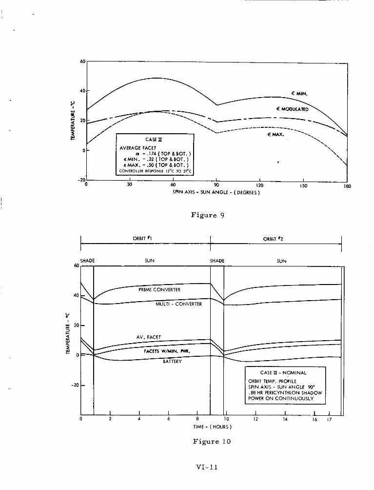
60
r MIN.
E MODULATED
-* --z \ -. ----- --.
-\ 20 --- _ _ _ _ _ _ --------
E MAX. .. \ '. '---- --.
CASE II '\
\ Q =.174(TOP&BOT.) '\
\ \
0
t MIN. = .32 ( TOP 8 BOT. ) t MAX. = S O (TOP 8 BOT. )
CONTROLLER RESPONSE 1Z0C TO 2YC
-201 I 1 1 I I 0 30
SPIN AXIS - SUN ANGLE - ( DEGREES )
Figure 9
t ORBIT I 1 ORBIT #2 I 1 SHADE SUN SHADE SUN
PRIME CONVERTER
Y
AV. FACET
FACETS W/MIN. PW.
BATTERY
CASE n - NOMINAL
ORBIT TEMP. PROFILE SPIN AXIS - SUN ANGLE 90' .88 HR PERICYNTHION SHADOW POWER ON CONTINUOUSLY
10 12 14 16 17 TIME - ( HOURS )
Figure 10
VI- 11

80
6C
4c
2c
t
-2t
-4(
- 6(
t ORBIT I ORBIT % 2
SHADE POWER
ON
SHADE SUN SUN 'OWER POWER POWER OFF OFF O N
7 HR. LOCKOUT
MIN. PWR. FACET
I I I I 2 4 6 8
SHADE SHADE SUN POWER , P,"rFER POWER
OFF
SUN POWER
O N
1 7 HR. LOCKOUl
9 MULTI - CONV.
ORBIT TEMP. PROFILE
1.72 HR. APOCYNTHION SHADOW SPIN AXIS - SUN ANGLE 180"
I 12 14 16
TIME - (HOURS )
Figure 11
VI-12

I- LL
L 4 LL LL c 4 a
4 3
\
24
N N
w
L
2
0
ul 0:
3 E =
r Y
I Y
I-
o
PD
0
*
N
0
X- 311fUWRIM W31
VI- 13

OPTIONAL FORM NO. 10 5010-104
UNITED STATES GOVERNMENT
Mem o ran dum APPENDIX VI1
TO : P.G. Marcotte - 672 DATE: 1 O/ 8/63
FROM : L.W. S l i f e r - 636, l S.G. McCarron - 636,l
SUBJECT: Anchored I M P Solar Paddles
The express ion f o r t h e normalized e f fec t ive-paddle-area of t h e three-paddle IMP s a t e l l i t e as a func t ion of paddle-spar ang le , paddle-pi tch ang le , sun- l ine sp in -ax i s ang le , and angu- l a r r o t a t i o n about t h e s p i n a x i s w a s programmed on t h e IBM 7090. The optimum average normalized e f fec t ive-paddle-area for a complete range (0 t o T ) of sun - l ine sp in -ax i s anglg occurs a t paddle-arm and paddle-pi tch ang le s equal t o 90 and 35O, r e s p e c t i v e l y . This on t h e average g i v e s , w i t h a s l i g h t margin, t h e power requirements f o r t h e proposed l u n a r IMP. (Figure 1 )
Under t h e s e c o n d i t i o n s , minima of t h e normalized e f f e c t i v e - paddle-area versus sun- l ine sp in-axis angle occur a t sun - l ine sp in -ax i s a n g l e s of 60 ef fec t ive-paddle-area (where one paddle 20" x 27.6", weighing 6.6 lb s . (max,), g i v e s 32 w a t t s w i t h normal i n c i d e n t s u n l i g h t ) v e r s u s angular r o t a t i o n about t h e s p i n axis f o r t h e s e condi- t i o n s is shown i n t h e Figure 2. The average power pe r revolu- t i o n is 47 wat ts inoboth c a s e s ; however, a minimum of 36.2 w a t t s occurs a t 120 r o t a t i o n i n t e r v a l s ,
0 and 120°, A p l o t of t h e normalized
Shadow e f f e c t s have been cons idered from a q u a l i t a t i v e s t a n d p o i n t on ly , but are not expected t o p re sen t a problem f o r t h i s conf igu ra t ion .
S ince t h e s e r e s u l t s provide only a s l i g h t margin, s e v e r a l f a c t o r s should s t i l l be cons idered:
1. W i l l vo l t age pu l s ing (3 pe r r e v o l u t i o n ) be t o l e r a b l e , i o e o , can t h i s be adequately taken care of i n t h e r e g u l a t o r design?
2, How s e r i o u s are occas iona l undervol tage condi t ions?
3. Can a d d i t i o n a l s o l a r ce l l s (-10%) be used e i t h e r by ex tens ion of t h e paddle width or by inc lud ing body-mounted cel ls?
&- w * *ka S G . M C b Luther W, S l i f e r , J r , S. Go McCarron S o l a r Power Sources Sec t ion S o l a r Power Sources Sec t ion Space Power Technology Branch Space Power Technology Branch
Enc: Fig. 1 & 2
VII-1

-0 0.
VI1 - 2

0 0 0 0
0 0 1 -0:
II II II
a m 3
0 0 0
%:8S I I I1 I I
a m 3
-t 9
'0.
*. *. e. **.
f . ..***
*.e*
,.**
> i
vu-3

OPTIONAL FORM NO. 10 5010-1 04
UNITED STATES GOVERNMENT
Memorandum TO Mr. J. J. Madden
Project Resources Office
APPENDIX VI11
DATE: August 13, 1963
FROM : Mr. G. C. Kronmiller, Jr. Project Manager, Goddard Range and Range Rate System'
SUBJECT: Transponder Power Required t o Track IMP D&E at Lunar Distances
The following i s a calculation of the power in the down-link:
Distance Transmit Frequency
250,000 n m 136 m c s
Antenna Gain (Transmit) 0 db Antenna Gain (Receive) t19 db
Space Loss 188 db Losses (Polarization, Line, Misc.) - 6 db
Total Loss - - - -175 db
Receiver N.F. t 3 db; 10 cps B W = t 10 db Receiver 0 db S / N level = 174 dbm t 13 db = -161 dbm Threshold for t 20 db S/N = 141 dbm
C a r r i e r Power Transmitted = X dbm C a r r i e r Power Transmitted = -141 dbm t175 db C a r r i e r Power Transmitted = t34 dbm C a r r i e r Power Transmitted = 2.5 Watts Sidetone Power = t 3 db = t2.5 Watts
Total Power Required --5 Watts
Therefore , t o insure adequate performance at l eas t 6 watts of t ransmit ted power should be provided for the ranging function.
G. C. Kronmiller, Jr. Project Manager
Goddard Range and Range Rate System
5 3 1 - 1 GC K:dkd
VI11 - 1

OPTIONAL FORM NO. IO 5010- 104
UNITED STATES GOVERNMENT
Memorandum TO : Paul Marcotte
Systems Integration Branch
APPENDIX IX
DATE: September 25, 1963
FROM : William R. Schindler Del ta Project Manager
SUBJECT: Planning Information on a n IMP D & E Mission and S-64 on Delta
REFERENCE: (a) Memo f rom P. Marcotte to W. R. Schindler dtd. 21 Aug. 63 (b) Memo f rom P. Marcotte t o W. R. Schindler dtd. 11 Sept. 63 (c) Memo f rom J. Kork t o W. R. Schindler dtd. 24 June 63 (d) Memo f rom W. R. Schindler to P. Marcotte dtd. 3 Sept. 63
The following information is in response t o the reference (a) and (b) memoranda.
Ideally, a lunar orbi ter should be launched so a s t o intercept the moon at maximum negative declination. Such launch t imes will occur on 4 De- cember 1964, 14 June 1965, and approximate six-month multiples of these dates. Spacecraft orientation can be controlled so that spin axis-sun angle variations would be 30" to 150" o r 150" to 30" during the initial four months of satell i te lifetime.
The 180-pound payload weight used in the reference ( c ) study was the anticipated maximum for the TAD-X2 58 combination. flight performance data is evaluated, the nominal 180-pound figure can be used for planning purposes. When such data is available, and spacecraft weight, orbit parameters and launch t ime a r e f i r m l y established, an exact flight sequence and associated success probabilities f o r desirable orbi ts can be prepared. In the meantime, it i s reasonable to use the information previously furnished in reference (c) and (d) for planning purposes. Elab- oration o r refinement of the calculations cited therein would be quite ex- tensive and costly, and would provide little o r no additional data which might influence a "feasibility" decision.
Until actual TAD
Enclosure 1 is a summary of orbit pa rame te r s for the 100 runs of the re ference (c) study. cynthian direction (line of apsides) and the sun, f o r the initial orbit only. The resulting t ra jectory will be a re t rograde orbit, with the pericynthian point rotating in the direction of the sun. Rate of change of sun angle can- not, however, be readily established. This would require a determination of the ra te of change of the orbital plane-ecliptic angle and the rotational ra te of the intersection of these planes, all of which would require an un- warran ted level of effort at this time.
The las t column, 4, i s the angle between the pe r i -
The reference (c) study included the 71-pound J P L "Syncom" fourth
It was learned that J P L has developed a titanium case for this stage motor with a velocity increment of 3684 fps for a 18O-pound space- c raf t ,
IX- 1

motor which w i l l be approximately four pounds lighter. "on shelf" motor which i s applicable to the IMP D&E mission i s the modified Thiokol TE-375 which weighs 85 pounds and has a velocity increment of 4830 fps for a 174-pound spacecraft.
The only other
To clarify a reference (d) statement concerning S-64, a TAD X-258 combination is capable of placing a payload of approximately 268 pounds into a 200-mileperigee t r ans fe r orbit. It is estimated that a 125-pound engine would be required to "kick" the spacecraft into a 24-hour orbit thus permitting a payload weight (exclusive of engine) of approximately 143 pounds. this requirement. (signus 15) which weighs 110 pounds, with a velocity increment of ap- proximately 4800 fps for a 106-pound spacecraft . motor appears t o be straightforward but involves the necessary de- velopment and qualification of a new engine.
We a r e not aware of an "on shelf" motor which mee t s Aerojet is developing a 15-inch spherical motor
Scaling-up an existing
W i l l i a m R. Schindler Delta Project Manager
Enclosure IMP D & E Orbit Results
IX-2

. .
O m N I II
I t
ci" 9
IX-3

I 0
M 1 9 b
M
B
IX -4

0 N 9
I
IX-5
0 m N
I
I I
2- 3b

* * 00
- 0 N M 9 d
m o * o d d
* M
b d
03 M
03 9 d
M 9
m 9 M
m b
4 4
In m m
- N * m 9 d
N m m M
* m m M
In 0
03 9 N l c o
0 M N
I
I X - 6

IX-7

4 4
b r - r - a m a
a m N O r - r - a m
o m N a 0 0 N m
M I-- m M r- ..
4 - I-- * 0 N
m c o r - 0 w I - - o= 0-
4
r - m N O * 4 N m
m N
(r N
4
r- * m 4
Ln I - - 0
m N a r -
m m m 0 0 0 ~ 0 ~ 0 0 0 r -
m * o ~ o L n o 4 r - o r - r - b r - r - r - r - I - - I - - I - -
m o I - -
a r - G 4
0 M N I
II
ci" 5:-
IX-8

0 rr) N I
II
j"
IX-9

ANGLE OF PERICYNTHION WITH RESPECT TO SUN FOR DIMPLE
I
I I
1 I I I I I I 1
0" 30" 60" 90 ' 120" 150" 180"
SYMBOLS
t, - Lunar injection t ime (Hrs )
rp - Pericynthion radius ( K m )
r, - Apocynthion radius (Km)
e - Orbital eccentricity
i
T - Orbital period ( H r s )
rr - Radial distance f r o m the center of moon at re t ro-f i r ing (Km)
Vi - Velocity before re t ro-f i r ing ( fps)
ai - Angle between the spin axis and velocity vector a t r e t r o (Deg)
Ot4- Retro-window ( H r s )
A, - Longitude of subsatellite point at the t ime of re t ro-f i r ing (degrees ;
- Orbital inclination with respect ecliptic plane (Deg)
negative west, positive eas t )
Li = -23" (i.e., approx. const. = 2 3 " s )
4 - Angle between the pericynthion direction and the sun (Deg)
IX- 10