ind310drive installation manual - mettler toledo
TRANSCRIPT

IND110 Load Cell Signal Converter Technical Manual
17041600A (5/04).00


CUSTOMER FEEDBACK Your feedback is important to us! If you have a problem with this product or its documentation, or a suggestion on how we can serve you better, please send your feedback via email to: [email protected].
PRECAUTIONS • READ this manual BEFORE operating or servicing this equipment and FOLLOW
these instructions carefully.
• SAVE this manual for future reference.
WARNING! TO AVOID DAMAGE TO THE PCB OR LOAD CELL, REMOVE POWER FROM THE IND110
TERMINAL AND WAIT AT LEAST 30 SECONDS BEFORE CONNECTING OR DISCONNECTING ANY WIRES.
CAUTION BEFORE CONNECTING/DISCONNECTING ANY INTERNAL ELECTRONIC COMPONENTS OR
INTERCONNECTING WIRING BETWEEN ELECTRONIC EQUIPMENT ALWAYS REMOVE POWER AND WAIT AT LEAST THIRTY (30) SECONDS BEFORE ANY CONNECTIONS OR
DISCONNECTIONS ARE MADE. FAILURE TO OBSERVE THESE PRECAUTIONS COULD RESULT IN DAMAGE TO OR DESTRUCTION OF THE EQUIPMENT AND/OR BODILY HARM.
CAUTION OBSERVE PRECAUTIONS FOR HANDLING ELECTROSTATIC SENSITIVE DEVICES.
WARNING! WHEN THIS EQUIPMENT IS INCLUDED AS A COMPONENT PART OF A SYSTEM, THE RESULTING DESIGN MUST BE REVIEWED BY QUALIFIED
PERSONNEL WHO ARE FAMILIAR WITH THE CONSTRUCTION AND OPERATION OF ALL COMPONENTS IN THE SYSTEM AND THE POTENTIAL HAZARDS INVOLVED. FAILURE TO OBSERVE THIS PRECAUTION COULD
RESULT IN BODILY HARM AND/OR PROPERTY DAMAGE.

DECLARATION OF CONFORMITY
Konformitätserklärung Déclaration de conformité
Declaración de Conformidad Conformiteitsverklaring
Dichiarazione di conformità We: Mettler-Toledo (ChangZhou) Scale & System Ltd. 111 ChangXi Road, ChangZhou ,JiangSu,People’s Republic of China,213001
declare under our sole responsibility that the product, erklären, in alleiniger Verantwortung, daß dieses Produkt, déclarons sous notre seule responsabilité que le produit, declaramos, bajo nuestra sola responsabilidad, que el producto, verklaren onder onze verantwoordelijkheid, dat het product, dichiariamo sotto nostra unica responsabilitá, che il prodotto, Model/Type:IND110
to which this declaration relates is in conformity with the following standard(s) or other normative document(s). auf das sich diese Erklärung bezieht, mitder/den folgenden Norm(en) oder Richtlinie(n) übereinstimmt. Auquel se réfère cette déclaration est conforme à la (aux) norme(s) ou au(x) document(s) normatif(s). Al que se refiere esta declaración es conforme a la(s) norma(s) u otro(s) documento(s) normativo(s). Waarnaar deze verklaring verwijst, aan de volende norm(en) of richtlijn(en) beantwoordt. A cui si riferisce questa dichiarazione è conforme alla/e sequente/i norma/e o documento/i normativo/i.
EC Marking EC Directive standards:
89/336/EEC Electromagnetic Compatibility (EMC)
EN55022 Class B EN50082-1 EN61000-3 -2 EN61000-3 -3
73/23/EEC Low Voltage Electrical Equipment
EN61010-1
ChangZhou,May 11, 2004,Mettler-Toledo (ChangZhou) Scale&System Ltd.
David Zheng Yang JiaWu President Quality Assurance Manager

© METTLER TOLEDO 2004
No part of this manual may be reproduced or transmitted in any form or by any means, electronic or mechanical, including photocopying and recording, for any purpose without the express written permission of METTLER TOLEDO.
U.S. Government Restricted Rights: This documentation is furnished with Restricted Rights.
Copyright 2004 METTLER TOLEDO. This documentation contains proprietary information of METTLER TOLEDO. It may not be copied in whole or in part without the express written consent of METTLER TOLEDO.
METTLER TOLEDO reserves the right to make refinements or changes to the product or manual without notice.
COPYRIGHT METTLER TOLEDO® is a registered trademark of METTLER TOLEDO. All other brand or product names are trademarks or registered trademarks of their respective companies.

COPYRIGHT METTLER TOLEDO® is a registered trademark of METTLER TOLEDO. All other brand or product names are trademarks or registered trademarks of their respective companies.
METTLER TOLEDO RESERVES THE RIGHT TO MAKE REFINEMENTS OR CHANGES WITHOUT NOTICE.
FCC Notice This device complies with Part 15 of the FCC Rules and the Radio Interference Requirements of the Canadian Department of Communications. Operation is subject to the following conditions: (1) this device may not cause harmful interference, and (2) this device must accept any interference received, including interference that may cause undesired operation.
This equipment has been tested and found to comply with the limits for a Class A digital device, pursuant to Part 15 of FCC Rules. These limits are designed to provide reasonable protection against harmful interference when the equipment is operated in a commercial environment. This equipment generates, uses, and can radiate radio frequency energy and, if not installed and used in accordance with the instruction manual, may cause harmful interference to radio communications. Operation of this equipment in a residential area is likely to cause harmful interference in which case the user will be required to correct the interference at his or her own expense.

For your notes
Contents Chapter 1.0 Contents Introduction ................................1-6
Chapter 1.0 Introduction ..............................................1-1
Chapter 2.0 Models .....................................................2-1
Chapter 3.0 Specifications ...........................................3-1
Chapter 4.0 Dimensions .............................................4-1
Chapter 5.0 Installation ...............................................5-1 Load cell connections ................................................................. 5-1 Load cell Selection ..................................................................... 5-2 Module mounting details ............................................................. 5-3 Analog Output 4/20 mA Connections ............................................ 5-3 Power supply wiring ................................................................... 5-6 Setpoint Output Connections ........................................................ 5-7 Calibration................................................................................. 5-8
Chapter 6.0 Service.....................................................6-1

1-1
Chapter 1.0 Introduction
Electrically, the IND110 Signal Converter provides an accurate and economical way to convert an analog strain gauge load cell(s) signal to a standard analog process signal. It does this by conditioning the analog input, converting it to a digital signal, normalizing and filtering it and then converting it back to an analog 4/20 mA signal. It would then be typically sent to a remote analog input such as a PLC.
In addition to the 4/20 mA output signal, two discrete setpoint outputs are provided for high and low level signaling.
Mechanically, the IND110 is self contained in a plastic housing for installation onto a 35 mm DIN rail or optionally installed in either a stainless steel IP66 enclosure or a cast aluminum explosion proof enclosure when environmental protection is required.

IND110 Technical Manual
1-2
For your notes

2-1
Chapter 2.0 Models
METTLER TOLEDO offers one standard plastic housing model of the IND110 Signal Converter. The IND110 is not suitable for mounting into a harsh environment without a protective enclosure.
An optional stainless IP66 rated enclosure with gasket is available separately and is shown below. Order by CIMF number 64053670.
Figure 1
Figure 2

IND110 Technical Manual
2-2
An optional cast aluminum explosion proof (Flameproof) enclosure is available when installation in hazardous areas is required by ordering part number 17041800A. It is rated by the manufacturer for use in a Class I Group C,D; Class II Group E,F,G; Class III environment when installed per the manufacturer’s recommendations.
Figure 3

3-1
Chapter 3.0 Specifications
Physical Dimensions (W x D x H)
3.9 x 2.9 x 2.2 inches 100 x 74 x 57 mm
Enclosure Material Plastic Mounting DIN rail (35 mm) External DC Power Requirements
20 to 28 VDC, 300 mA max, 8 watts Class 2 power supply
Load Cell input Excitation:10 VDC, 120mA max,(4 – 350 ohm cells) Acceptable Load cells:1.5 to 3 mV/V with full bridge Span adj. range: 25 to 110% of cell capacity @ 2mV/V Zero adj. range: 0 to100% of load cell output @ 2mV/V
Discrete Outputs (Setpoints)
One Low and one High level output, open collector 5 to 30 VDC 75mA max sink current. Transistor ON when weight < setpoint value. (Transistor emitter connected to supply common)
Analog Output Signal: 4 to 20 mA, (1 mA and 24 mA limits) Load resistance range: 0 to 500 ohms Output Resolution: 1 part in 4000 min. @ 25% cell span Output Linearity: ⟩ 0.012% max. Temp Stability: #20 PPM/°C (span), 50 PPM/°C (zero) Conversion time: 50 mS (20 updates/sec) Isolation: Circuit common connected to supply common
Calibration DIP switch selection to enable front panel calibration of load cell zero/span and setpoint low/high limits.
button: Toggle between modes + button: Increment value - button: Decrement value
LED Indicators Power: ON with +24VDC applied HI : ON when load cell signal < HI setpoint LO : ON when load cell signal < LO setpoint
Environmental Conditions Operating temp:14ּנ to 112ּנ F (-10ּנ to 45ּנ C) Storage temp: -4° to 158° F (-20° to 70° C) Humidity: ≤ 95% RH non condensing Protection: IP2X DIN rail mounting (module) IP66 (mounted in stainless enclosure) Cl I,2 Gp C-G (mounted In exp.Proof encl.)
RFI RFI susceptibility: # 8μA change for 3V/Meter (26 to 1000mHZ) RFI emissions: meets FCC class A & EN50022-A. Static discharge: N.A.
Agency approvals
CUL listed for USA & Canada,

IND110 Technical Manual
3-2
For your notes

4-1
Chapter 4.0 Dimensions
METTLER TOLEDO
IND110
PWR
Lo
Hi
5577 7744
110000
Module Dimensions Figure 4
4.0”(101.6)
7.5”(190.5)
2.75”(69.9)
6.25”(158.75)
7.0”(177.8)
Stainless Steel Enclosure Dimensions Figure 5

IND110 Technical Manual
4-2
Explosion Proof Enclosure Dimensions Figure 6
7.75”(196.9)
7.0”(177.8)
6.0”(152.4)
8.0”(203.2)
5.0”(127)
6.75”(171.5)

5-1
Chapter 5.0 Installation
Load cell connections Up to (4) 350 Ohm full bridge strain gauges may be connected in parallel. The excitation voltage supplied by the IND110 is 10 VDC with a source current of 120mA max.
WARNING THE IND110 IS NOT INTRINSICALLY SAFE. THE LOAD CELL LINES MUST NOT BE OPERATED IN A HAZARDOUS AREA WITHOUT AN APPROVED INTRINSIC SAFE BARRIER. FAILURE TO OBSERVE THESE PRECAUTIONS COULD RESULT IN BODILY HARM AND/OR PROPERTY DAMAGE.
Load cell connections must be made with shielded cable as shown below. Note that the IND110 SHIELD terminal is electrically connected to the IND110 circuit and 24VDC common. Therefore, Mettler Toledo recommends an isolated 24VDC source to prevent stray ground loop currents from affecting load cell signal integrity. The load cell cable shield should not be externally connected to any grounds and must remain floating at the load cell end.
Figure 7

IND110 Technical Manual
5-2
Load cell Selection Before any load cells are connected, determine if intended load cells will work correctly. 1. First identify
• Full scale system capacity. Example: If system span is 0 -10,000 lbs, then 10,000 is the capacity.
• Capacity of each load cell (nameplate rating) • Output rating of each load cell in mV/V (check nameplate) • Bridge resistance of each load cell (check nameplate)
2. Calculate the parallel resistance of load cells
• Divide bridge resistance by # of cells(Ex:4 cells 350 ohms/cell = 87.5 ohms) (87 ohms is the lowest resistance allowed)
3. Calculate the full scale load cell signal output
a. Mv = (system capacity) x (single cell output rating) x (excitation voltage) (single load cell capacity) x(number of cells) weighing range = 10,000 pounds Single cell output rating = 2 mv/v Single cell capacity = 5000 pounds Number of cells = 4 Excitation voltage = 10
Mv = 10,000 lb x 2 mv/v x 10 v = 200000 = 10 mv 5000 lb x 4 cells 20000
b. The minimum full scale signal is 2 millivolts so 10 mv is acceptable.
(Another way to approximate the signal is to allow no less than 10% of the load cell capacity for span. In the above example 10% of (4) 5000 pound cells is 2000 pounds. The above example weighing range is 10,000 pounds. It is 4 times the 2000 pounds minimum acceptable weight and is OK).

IND110 Technical Manual
5-3
Module mounting details Enclosure installation details The enclosures illustrated below do not address hardware mounting/ wiring needs. The stainless enclosure has two plastic cord bushings to pass cables into the enclosure. The plugged openings are provided for wiring flexibility, if needed. The installer must provide correct fittings according to National and local codes.
The explosion proof enclosure has two tapped 3/4” NPT holes only. Sealed explosion proof fittings are required to complete the installation. The installer must provide them, insure they are properly installed and sealed according to National and local codes prior to use.
The view below illustrates the module position when mounted in the optional stainless steel enclosure. It snaps onto the DIN rail located inside the enclosure assisted by retracting the plastic module tab with a screwdriver as shown above
This detail illustrates a screwdriver blade retracting the module tab so it can snap onto the DIN rail. Plastic retractable
module tab.
Figure 8
Figure 9

IND110 Technical Manual
5-4
The views below illustrate module installation into the Nema 7/9 optional explosion proof enclosure. It snaps onto the DIN rail in the same manner as above but because of space limitations, snap the module onto the DIN rail first and then install into the enclosure.
First, install the M6 screws loosely into predrilled holes in the enclosure. Next, place module and rail onto screws. The rail slot is long enough to slide onto one screw then center it between the two.
Position the rail as shown and tighten screw. Center the module and tighten other screw to complete the installation.
Figure 10
Figure 11

IND110 Technical Manual
5-5
Analog Output 4/20 mA Connections The output signal provided is a standard 4/20 mA signal commonly used for many industrial process control and PLC applications. Since this signal is analog in nature, it must be well shielded, properly grounded and protected from higher voltage signals. Do not route this signal cable with power wiring.
Proper grounding is important. This instrument connects the load cell shield, power supply common and 4/20 mA common lines together. As a result, connect only one of these points to an earth ground. Many process control instruments connect their 4/20 mA common to earth internally. If true, this system must remain floating without a ground connection. Test for process control equipment ground continuity before wiring is completed. If it is not grounded, connect the IND110 at the load cell shield terminal to earth ground. If it IS connected to ground, be sure the IND110 wiring is NOT grounded.
The 4/20 mA current loop external wiring should be two conductor #20 AWG (0.51MM2) (MIN) shielded cable. Use Belden #8759 or equal and connect as shown below.
Figure 12
IND110 Technical Manual
5-6
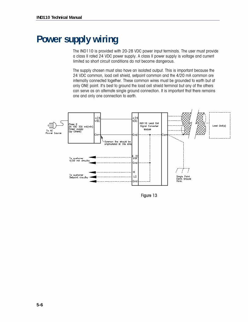
Power supply wiring The IND110 is provided with 20-28 VDC power input terminals. The user must provide a class II rated 24 VDC power supply. A class II power supply is voltage and current limited so short circuit conditions do not become dangerous.
The supply chosen must also have an isolated output. This is important because the 24 VDC common, load cell shield, setpoint common and the 4/20 mA common are internally connected together. These common wires must be grounded to earth but at only ONE point. It’s best to ground the load cell shield terminal but any of the others can serve as an alternate single ground connection. It is important that there remains one and only one connection to earth.
Figure 13
IND110 Technical Manual
5-7
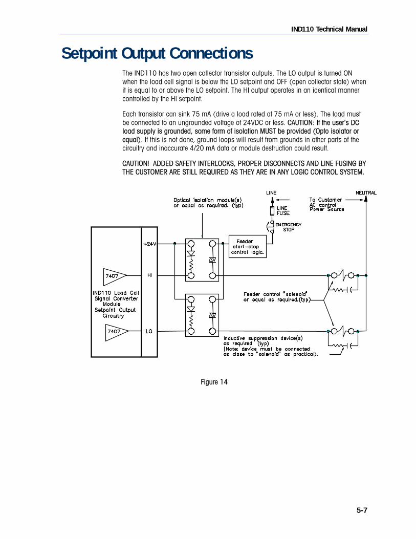
Setpoint Output Connections The IND110 has two open collector transistor outputs. The LO output is turned ON when the load cell signal is below the LO setpoint and OFF (open collector state) when it is equal to or above the LO setpoint. The HI output operates in an identical manner controlled by the HI setpoint.
Each transistor can sink 75 mA (drive a load rated at 75 mA or less). The load must be connected to an ungrounded voltage of 24VDC or less. CAUTION: If the user’s DC load supply is grounded, some form of isolation MUST be provided (Opto isolator or equal). If this is not done, ground loops will result from grounds in other parts of the circuitry and inaccurate 4/20 mA data or module destruction could result.
CAUTION! ADDED SAFETY INTERLOCKS, PROPER DISCONNECTS AND LINE FUSING BY THE CUSTOMER ARE STILL REQUIRED AS THEY ARE IN ANY LOGIC CONTROL SYSTEM.
Figure 14

IND110 Technical Manual
5-8
Calibration
The above chart illustrates the calibration and setup functions. Position the DIP switch located on the front panel to select the desired function. After calibration is complete, set all switches to OFF to store the settings.
SWITCHES LED status OPERATING MODE 1 2 3 4 5 6 LO HI
CONDITIONS NOTES
on on Weight below setpoint
off on Weight between LO & HI setpoint
off off Weight above HI setpoint
Operational status Normal conditions
Normal Weigh Mode
Off
Off
Off
Off
Off
Off
flash flash Error Analog=0 mA. Setpoint=OFF
off flash Coarse zero adjustment mode
Zero calibration
On
Off
Off
Off
Off
Off
flash off Fine zero adjustment mode
off flash Coarse span adjustment mode
Span Calibration
Off
On
Off
Off
Off
Off
flash off Fine span adjustment mode
off flash Coarse HI setpoint adj. mode
HI setpoint setting
Off
Off
On
Off
Off
Off
flash off Fine HI setpoint adj. Mode
off flash Coarse LO setpoint adj. Mode
LO setpoint setting
Off
Off
Off
On
Off
Off
flash off Fine LO setpoint adj. Mode
Use key to toggle from coarse to fine modes. LO LED flashes for coarse. HI LED flashes for fine. Use + key to increment or Use – key to decrement analog output voltage. Press and hold key for faster speed adjustment.
METTLER TOLEDO
IND110
PWR
Lo
Hi
SET key INC key DEC key -
+
SetpointOutput 4/20 mA
OutputDC Power Input
Power ON LED Hi Setpoint LED Calibration switches Lo Setpoint LED
Analog load cell input

IND110 Technical Manual
5-9
Calibration
Calibration is done with DIP switches 1-4 and the three buttons. For normal weighing all the DIP switches are OFF. For calibration, DIP switches 1-4 are switched ON as required to calibrate the weigh mode ZERO, weigh mode SPAN, LO setpoint cutoff and HI setpoint cutoff.
Set Weigh Mode Zero Unload scale. Set DIP switch 1 to ON (all other switches OFF). HI LED will flash (coarse setting). With a calibration current meter connected to the output, use “+” and “-“ buttons to adjust output current to desired “zero load” value (Typically 4 mA). If fine adjustment is required, depress “ “ button until LO LED flashes. Use the “+” and “-“ buttons for fine adjustment. When correct zero value is obtained, return DIP switch 1 to OFF position. The zero load current output is stored.
Set Weigh Mode Span Load scale with the maximum load weight corresponding to the desired current output (Typically 20 mA). Set DIP switch 2 to ON (all other switches OFF). HI LED will flash (coarse setting). use “+” and “-“ buttons to adjust output current to desired “full load” value (Typically 20 mA). If fine adjustment is required, depress “ “ button until LO LED flashes. Use the “+” and “-“ buttons for fine adjustment. When correct span value is obtained, return DIP switch 2 to OFF position. The full load current output is stored. NOTE: It is possible to calibrate with a value less than full load weight. Simply calculate current output value needed to represent the load applied and adjust current output for that value. However, the lower that value is, the lower the setting accuracy obtained. Always try to use the highest calibration weight possible.
Set HI setpoint cutoff value. Load scale with a value equal to the desired HI setpoint cutoff point and note the 4/20 mA current output reading. Alternatively, calculate the output current at the desired load cutoff point. Remember the value and turn ON DIP switch 3 (all other switches OFF). HI LED will flash. Using the “+” and “-“ buttons, depress them until the 4/20 mA output matches the remembered value. As with the weigh mode calibration, the “↵ “ button can be used to toggle into fine adjustment mode if needed. Return DIP switch 3 to OFF when complete.
Set LO setpoint cutoff value. This setpoint is identical to the HI setpoint calibration except DIP switch 4 is used instead. Note: there is no significance to the HI and LO setpoint names. The HI can be set for the lowest value if desired. It is simply a way to keep track of the values. Also, it is not necessary to use either setpoint. Do not program if not needed.


6-1
Chapter 6.0 Service
Before servicing an IND110, make sure the power has been removed. There are no field serviceable parts within the IND110.
WARNING DISCONNECT ALL POWER TO THIS UNIT BEFORE INSTALLING, SERVICING OR CLEANING. FAILURE TO DO SO COULD RESULT IN BODILY HARM AND/OR PROPERTY DAMAGE.

6-2
For your notes


1900 Polaris Parkway Columbus, Ohio 43240 www.mt.com
P/N: 17041600A
METTLER TOLEDO® is a registered trademark of Mettler-Toledo, Inc.
©2004 Mettler-Toledo, Inc.
Printed in USA
17141600A