installation and operation manual - sprinkler...
TRANSCRIPT

ET Manager SeriesInstallation and Operation Manual
Rain Bird® ET Manager Series - Installation and Operation Manual
Table of Contents
2
1. Introduction . . . . . . . . . . . . . . . . . . . . . . . . . . . . . . . . . . . . . . . . . . . . .3Principles of Weather Based Water Management . . . . . . . . . . . . . . . . .3The Weather Reach Water Management System . . . . . . . . . . . . . . . . .4Getting to Know your Rain Bird ET Manager . . . . . . . . . . . . . . . . . . . . .5
LCD Display . . . . . . . . . . . . . . . . . . . . . . . . . . . . . . . . . . . . . . . .5Valve Group A & B Indicator Lights . . . . . . . . . . . . . . . . . . . . . . .6Attention Indicator Light . . . . . . . . . . . . . . . . . . . . . . . . . . . . . . .6Cursor and Navigation Buttons . . . . .6Override Button . . . . . . . . . . . . . . . . . . . . . . . . . . . . . . . . . . . . . .7Terminal Cover . . . . . . . . . . . . . . . . . . . . . . . . . . . . . . . . . . . . . . .7
Specifications . . . . . . . . . . . . . . . . . . . . . . . . . . . . . . . . . . . . . . . . . . .7Resource CD Included with your ET Manager . . . . . . . . . . . . . . . . . . . .8Getting Ready to use Your ET Manager . . . . . . . . . . . . . . . . . . . . . . . .8
2. Installation . . . . . . . . . . . . . . . . . . . . . . . . . . . . . . . . . . . . . . . . . . . . . .9Warnings . . . . . . . . . . . . . . . . . . . . . . . . . . . . . . . . . . . . . . . . . . . . . . .9Installation Check List . . . . . . . . . . . . . . . . . . . . . . . . . . . . . . . . . . . . .9Select Location . . . . . . . . . . . . . . . . . . . . . . . . . . . . . . . . . . . . . . . . . .9Mounting . . . . . . . . . . . . . . . . . . . . . . . . . . . . . . . . . . . . . . . . . . . . .10Wire Connections . . . . . . . . . . . . . . . . . . . . . . . . . . . . . . . . . . . . . . .11
Grounding . . . . . . . . . . . . . . . . . . . . . . . . . . . . . . . . . . . . . . . . .12Power . . . . . . . . . . . . . . . . . . . . . . . . . . . . . . . . . . . . . . . . . . . .12Wiring Diagrams . . . . . . . . . . . . . . . . . . . . . . . . . . . . . . . . . . . .13Optional Rain Gauge . . . . . . . . . . . . . . . . . . . . . . . . . . . . . . . . .13Optional External Antenna . . . . . . . . . . . . . . . . . . . . . . . . . . . . .15
Install Battery . . . . . . . . . . . . . . . . . . . . . . . . . . . . . . . . . . . . . . . . . .16
3. Programming . . . . . . . . . . . . . . . . . . . . . . . . . . . . . . . . . . . . . . . . . . .17Programming Options . . . . . . . . . . . . . . . . . . . . . . . . . . . . . . . . . . . .17
Using the ET Manager Programming Software . . . . . . . . . . . . . .17Manual Programming . . . . . . . . . . . . . . . . . . . . . . . . . . . . . . . .17
Manual Programming Steps . . . . . . . . . . . . . . . . . . . . . . . . . . . . . . .171. Data Source . . . . . . . . . . . . . . . . . . . . . . . . . . . . . . . . . . . . . .172. Output Method . . . . . . . . . . . . . . . . . . . . . . . . . . . . . . . . . . . .193. Site Specific Settings . . . . . . . . . . . . . . . . . . . . . . . . . . . . . . .19Irrigation Amount and Adjustment . . . . . . . . . . . . . . . . . . . . . . . .19Water Window . . . . . . . . . . . . . . . . . . . . . . . . . . . . . . . . . . . . . .20Available Watering Days . . . . . . . . . . . . . . . . . . . . . . . . . . . . . . .21Advanced Settings . . . . . . . . . . . . . . . . . . . . . . . . . . . . . . . . . . .214. Additional Settings and Options . . . . . . . . . . . . . . . . . . . . . . .24
Programming the Sprinkler Controller . . . . . . . . . . . . . . . . . . . . . . . .25Watering Days . . . . . . . . . . . . . . . . . . . . . . . . . . . . . . . . . . . . . .25Cycle Start Times . . . . . . . . . . . . . . . . . . . . . . . . . . . . . . . . . . . .26Station Run Times . . . . . . . . . . . . . . . . . . . . . . . . . . . . . . . . . . .26Non-ET Based Watering Schedules . . . . . . . . . . . . . . . . . . . . . .26
4. System Check . . . . . . . . . . . . . . . . . . . . . . . . . . . . . . . . . . . . . . . . . . . . . .27System Check . . . . . . . . . . . . . . . . . . . . . . . . . . . . . . . . . . . . . . . . . . . . . .27
Control Mode . . . . . . . . . . . . . . . . . . . . . . . . . . . . . . . . . . . . . . . . . . .27Weather Signal Test . . . . . . . . . . . . . . . . . . . . . . . . . . . . . . . . . . . . . .28Valve Control Test . . . . . . . . . . . . . . . . . . . . . . . . . . . . . . . . . . . . . . .29Water Window Settings . . . . . . . . . . . . . . . . . . . . . . . . . . . . . . . . . . .29Initial Moisture Levels . . . . . . . . . . . . . . . . . . . . . . . . . . . . . . . . . . . . .29
5. Routine Operation . . . . . . . . . . . . . . . . . . . . . . . . . . . . . . . . . . . . . . . . . . .30Weather Information . . . . . . . . . . . . . . . . . . . . . . . . . . . . . . . . . . . . . . . . .30Irrigation Status . . . . . . . . . . . . . . . . . . . . . . . . . . . . . . . . . . . . . . . . . . . . .31Information Log . . . . . . . . . . . . . . . . . . . . . . . . . . . . . . . . . . . . . . . . . . . . .33Status Messages . . . . . . . . . . . . . . . . . . . . . . . . . . . . . . . . . . . . . . . . . . . .34Attention Messages . . . . . . . . . . . . . . . . . . . . . . . . . . . . . . . . . . . . . . . . . .35
6. Determining Programmable Settings . . . . . . . . . . . . . . . . . . . . . . . . . . .41Site Assessment . . . . . . . . . . . . . . . . . . . . . . . . . . . . . . . . . . . . . . . . . . . .41
Sprinkler Controller and Station Information . . . . . . . . . . . . . . . . . . . .42Landscape Conditions . . . . . . . . . . . . . . . . . . . . . . . . . . . . . . . . . . . .43
ET Manager Settings . . . . . . . . . . . . . . . . . . . . . . . . . . . . . . . . . . . . . . . . .44Irrigation Control . . . . . . . . . . . . . . . . . . . . . . . . . . . . . . . . . . . . . . . .44Advanced Settings . . . . . . . . . . . . . . . . . . . . . . . . . . . . . . . . . . . . . . .46
ET Manager Scheduler . . . . . . . . . . . . . . . . . . . . . . . . . . . . . . . . . . . . . . .47
7. Troubleshooting . . . . . . . . . . . . . . . . . . . . . . . . . . . . . . . . . . . . . . . . . . . . .48ET Manager Troubleshooting . . . . . . . . . . . . . . . . . . . . . . . . . . . . . . . . . . .48Water Management Troubleshooting . . . . . . . . . . . . . . . . . . . . . . . . . . . . .49
8. Advanced Output Methods . . . . . . . . . . . . . . . . . . . . . . . . . . . . . . . . . . . .53Enable A then B . . . . . . . . . . . . . . . . . . . . . . . . . . . . . . . . . . . . . . . . . . . .53ET & Rain Pulse . . . . . . . . . . . . . . . . . . . . . . . . . . . . . . . . . . . . . . . . . . . .55ET Pulse with Weather Interrupt . . . . . . . . . . . . . . . . . . . . . . . . . . . . . . . . .57Using More than One Sprinkler Controller . . . . . . . . . . . . . . . . . . . . . . . . .59
9. Appendices . . . . . . . . . . . . . . . . . . . . . . . . . . . . . . . . . . . . . . . . . . . . . . . .60Appendix I. ET Manager Menu Structure . . . . . . . . . . . . . . . . . . . . . . . . . .60Appendix II: Default ET Manager Settings . . . . . . . . . . . . . . . . . . . . . . . . . .62Appendix III. ET Manager Site Assessment Worksheet . . . . . . . . . . . . . . . .63Appendix IV. Soil Texture by Feel Diagram . . . . . . . . . . . . . . . . . . . . . . . . .64Appendix V. Calculating Precipitation Rates and Station Run Times . . . . . . .65Appendix VI. ET Manager Settings Worksheet . . . . . . . . . . . . . . . . . . . . . .66Appendix VII. Sprinkler Controller Programming Worksheet . . . . . . . . . . . .67Appendix VIII: ET Manager Installation Checklist . . . . . . . . . . . . . . . . . . . . .68Appendix IX. ET Manager Status Report Worksheet . . . . . . . . . . . . . . . . . .69Appendix X. Master Valve and Pump Control Installation with ET Manager . .70
10. Glossary . . . . . . . . . . . . . . . . . . . . . . . . . . . . . . . . . . . . . . . . . . . . . . . . . .73
Rain Bird’s Professional Customer Satisfaction Policy . . . . . . . . . . . . . . .79

Rain Bird® ET Manager Series - Installation and Operation Manual
Table of Contents
3
1. IntroductionCongratulations on purchasing the Rain Bird ETManager! Your ET Manager (ETMi) works with almostall sprinkler controllers to automatically control water-ing based on current weather conditions bringingsmart control to your sprinkler system. Weather condi-tions affect how much water your landscape needs.With your ET Manager landscape watering will be fullyautomatic and more accurate.
Principles of Weather BasedWater ManagementThere are four key principles to the operation of the ETManager.
Principle #1:The soil is a reservoir: The purpose of watering is toreplenish the soil reservoir, which makes water avail-able for plants (see Figure 1). This reservoir has a limit-ed capacity based on soil type and root depth.
Principle #2:Weather Affects Landscapes: Landscapes need waterat changing rates based on weather conditions. Waterleaves plants and soil through evaporation. Becauseweather has a direct affect on evaporation, changingweather conditions have an effect on how often land-scape watering is needed.
Principle #3:Evaporation can be measured based on weatherconditions: Landscape, golf, and agricultural watermanagers have been using weather stations to measurethe loss of soil moisture caused by evaporation for over20 years.
Evapotranspiration, or ET, is a measurement of waterthat evaporates into the air from the soil and theamount of water that is used (transpired) by a plant. ETis used to determine how much water must be returnedto the landscape, either by rainfall or by using a sprin-kler system. ET is typically expressed in hundredths ofinches of water per day. ET losses are calculated usingmeteorological data measured with a weather station.Weather parameters used to calculate ET include: solarenergy, air temperature, wind speed, humidity, andrainfall.
Figure 2 shows that ET is highest in the hot summermonths, the time when your landscape needs the mostwater. Landscape, golf, and agricultural water managershave been using weather stations to measure the loss ofsoil moisture caused by evaporation for over 20 years.
Figure 2. Example of Evapotranspiration for One Year
Principle #4 Technology can provide automated watering: TheET Manager uses current weather conditions to auto-matically control watering.
Soil Reservoir
Figure 1. Soil Reservoir

Figure 3. Weather Reach Water Management System
Rain Bird® ET Manager Series - Installation and Operation Manual
1. Introduction
4
The Weather Reach WaterManagement SystemYour ET Manager receives a wireless weather signal fromthe Weather Reach Water Management System. TheWeather Reach Water Management System (Figure 3)automates commercial and residential sprinkler sched-ules using real-time weather conditions. A WeatherReach Signal Provider (WRSP) retrieves informationfrom local weather stations. The information is broad-cast as a weather signal via a paging radio frequency toyour ET Manager. The weather signal contains the mostrecent weather conditions including:
• Solar Energy
• Temperature
• Wind
• Humidity
• Rainfall
The ET Manager uses this data to compute water lossand control how often your sprinkler controller watersyour landscape.
* Weather Reach is a trademark of Irrisoft, Inc.
Weather Reach Signal ProviderYour Weather Reach Signal Provider (WRSP) retrievesweather information from local weather stations andsends the weather signal to your ET Manager. YourWRSP communicates with your ET Manager usingSignal Provider Codes (see chapter 4, Programming)programmed into your ET Manager. The SignalProvider Codes are available fromwww.rainbird.com/etmanager, where you can down-load and print an information sheet with specific infor-mation regarding your local WRSP.

Getting to Know your Rain Bird ET ManagerYour ET Manager automates control of the sprinklersystem. It reacts to weather information it receivesfrom the weather signal based on the settings pro-grammed in the device. The following basic knowledgewill identify elements of the ET Manager (see Figure 4),explain how to navigate through the ET Managermenus, and provides ET Manager Specifications.
LCD Display The display is used to view current operating conditions,monitor status, view settings, and make programmingchanges. On startup the LCD screen displays the Homescreen, which reports the following information:
Note: Status and Attention messages are a normaloperation condition. Refer to chapter 5, RoutineOperation, for more information on the Status andAttention messages.
Note: On initial startup the date and time is displayedas Jan 01 2000 12:00 am. Once the ET Managerbegins to receive the weather signal the date and timewill be set automatically. Date and time can also beset manually.
Note: After two hours with no keypad activity the dis-play reverts to the Home screen.
Note: The LCD display will refresh once a minute.
Note: If you are using an advanced Output Method,as described in chapter 8, the Home screen may dis-play different information.
Rain Bird® ET Manager Series - Installation and Operation Manual
1. Introduction
5
Figure 4. ET Manager Front Panel

LCD ContrastThe image contrast on the LCD may be adjusted ifneeded. Temperature and surrounding light conditionscan affect image visibility. To adjust the contrast, fromthe Home screen press à once.
Once the contrast screen is displayed, press and hold Œor Õ to adjust the image contrast. When the contrast isset to the desired setting, press À once to return tothe Home screen.
The LCD contrast screen displays the ET Manager serialnumber, the program version of your device, and thedate and time of the last signal.
Valve Group A & B Indicator Lights Your ET Manager controls two valve groups. For exam-ple, Valve Group A can be assigned and wired to lawnstations and Valve Group B to shrub stations. There isone Indicator Light for each group of valves, “A” and “B.”
A green light indicates watering is needed and the sprin-kler controller will be allowed to activate a valve. A redlight indicates watering is suspended or interrupteduntil watering is needed.
Attention Indicator Light A yellow light, or the Attention Indicator Light, signals acondition that you should be aware of. An attentionmessage is displayed on the Home screen. Please referto chapter 5, Routine Operation, for more informationon the attention messages.
Cursor and Navigation Buttons To navigate ET Manager menus, you need to under-stand the movement of the cursor and its location. The“�” symbol indicates the current cursor location. TheŒ, Õ, or À navigation buttons are used to positionthe cursor at the desired location. À is used to enterthe selected menu. Once in the desired menu or posi-tion, use Œ or Õ to change a value or select an option.à is used to go back, or to exit the screen.
To practice navigating using the cursor and navigationbuttons, try setting the Current Moisture Level for ValveGroup A or B. Menu paths like the one below are foundthroughout the manual to show which items within themenu and submenus need to be selected to access keyinformation or to adjust settings.
Example of a Menu path:
Main Menu �Settings �Irrigation Status �“A” Moisture Level
Below is a detailed explanation of how to follow thismenu path through your ET Manager.
From the Home screenaccess the Main Menu by pressing À.
In the Main menu, usethe Œ or Õ to scrollto Irrigation Status andpress À.
In the Irrigation Statusscreen, use the Œ or Õto scroll to “A” MoistureLevel and press À.
The �will be posi-tioned at the value ofthe Current Level.Use Œ or Õ to adjustthis level.
Once the amount is adjusted, use à to get back tothe Irrigation Status screen.
Rain Bird® ET Manager Series - Installation and Operation Manual
1. Introduction
6

Override ButtonIf the A or B IndicatorLight is red, your ETManager is interrupt-ing the output of thesprinkler controller. Ifyou need to manuallyactivate a valve from the sprinkler controller, press theOverride button, and the Valve Group A and B IndicatorLights will turn green enabling sprinkler output. Yoursprinkler controller can now be used to manually starta valve.
Once the Override button is pressed, the LCD displaywill change from the current screen to the Overridescreen.
An Override will allow watering for one hour, if moretime is needed press the Override button again or pressŒ for each additional hour of Override. Once the over-ride time has elapsed, watering will be interrupted asbefore. Press Õ to 0 hours to end manual override inthe ET Manager.
Terminal CoverTo access wire terminals, the terminal cover will need tobe removed. Press gently on the terminal cover releasewhile pulling out the bottom edge of the terminal cover.To completely remove the terminal cover, lift it off thetabs, exposing the wire terminals. To replace the termi-nal cover, insert the tabs into the tab holes, and the ter-minal cover release on the terminal cover until it is cor-rectly positioned back in place.
SpecificationsElectrical Specifications
• Power Supply: 12 to 30-volt AC/60Hz or 12 to35 VDC @ 0.22 (0.2) Amp max
• Contact Load: 4 Amp max. @ 30-volt AC max
• Operating Temperature Range: -15° to 65°C(5° to 149°F)
• Paging Radio Operating Temperature Range:0° to 50°C (32° to 122°F)
• Terminal Wire Gauge: 14 to 20 AWG
• Ground Lug Wire Gauge: 10 to 18 AWG
• Serial Communications: TTL level, 1x6Header, requires WR-USB Personal ComputerInterface
• Antenna Connection: BNC Female, 930 MHz
• Rain Gauge Sensor Voltage: 3.3 VDC
Cabinet - Indoor Wall Mount• Width: 5.5”
• Height: 6.5”
• Depth: 1.9”
Note: The ET Manager is an indoor mount only unit,unless mounting outdoors with the ETM-OE.
Optional Accessories• PN 635640: 110-volt AC Plug-in Power Supply
Transformer
• ETMi-ANT: ET Manager Remote Antenna
Note: The ET Manager contains a paging radio receiverwith a built-in antenna. Locations with a weak pagingsignal may require an external antenna.
Rain Bird® ET Manager Series - Installation and Operation Manual
1. Introduction
7

• ETM-OE: ET Manager outdoor enclosureoption made with heavy-duty weather resistantplastic and 110-volt AC outlets. This case islockable and the dimensions are 11 5⁄8" H x 9 1⁄2"W x 4 1⁄4" D
• ETM-RG: Tipping Bucket Rain Gauge (1mm/tip) w/ 30’ Cable.
ET FormulaEvapotranspiration (ETc) is calculated by the ETManager using data from the weather signal via thepaging system. The ET Manager uses the StandardizedReference Evapotranspiration Equation with a shortgrass reference, prepared by the American Society ofCivil Engineers.
Resource CD Included with your ET ManagerIncluded with your ET Manager is a resource CD con-taining helpful tools such as:
• ET Manager Simulation and Animations
• Printable versions of worksheets used andreferred to in this manual
• Rain Bird ET Manager Scheduler
• Printable versions of application notes
Getting Ready to use Your ET ManagerThe following chapters will walk you through how toinstall, program, and use your ET Manager.
• Installation, chapter 2
• Programming, chapter 3
• System Check, chapter 4
• Routine Operation, chapter 5
• Determining Programmable Settings, chapter 6
• Troubleshooting, chapter 7
• Advanced Output Methods, chapter 8
• Appendices, chapter 9
• Glossary, chapter 10
Rain Bird® ET Manager Series - Installation and Operation Manual
1. Introduction
8

2. Installation
Rain Bird® ET Manager Series - Installation and Operation Manual 9
2. InstallationTo install your ET Manager, follow the installationcheck list and instructions given in this chapter. YourET Manager is compatible with almost any type ofsprinkler controller. This chapter focuses on installingyour ET Manager with a standard sprinkler controller.Refer to chapter 8 for specific installation instructionson installing your ET Manager with advanced sprinklercontrollers.
Warnings• The ET Manager is intended for indoor use.
Outdoor installation locations require the useof an outdoor enclosure (ETM-OE).
• The ET Manager must be installed in compli-ance with local electrical codes.
• To prevent electrical shock and/or damage,make sure that all supply power is OFF to thedevice, the sprinkler controller, or any equip-ment being connected. Electrical shock cancause severe injury or death.
• 12 to 30-volts AC or 12 to 35-volts DC MUST beused to power this unit. DO NOT connect it to120 volts or greater.
• A ground wire, 10-18 AWG, MUST be connect-ed for electrical surge, equipment and personalprotection.
Installation Check List• Select Location
• Mounting
• Provide Power
• Grounding
• Wire Connections
• Optional Rain Gauge
• Optional External Antenna
• Install Battery
Select LocationFollow these guidelines to select a location for the ET Manager:
• It is best to install it adjacent to the sprinklercontroller.
• The ET Manager is not weather resistant.Install indoors ONLY unless using a weatherresistant enclosure (ETM-OE or TC-2).
• Optional outdoor enclosures designed for theET Manager are available. Use the modelETM-OE.
• Avoid electromagnetic interference. DO NOTinstall the ET Manager near motors, transform-ers or other high current electric equipment.
• Mount near eye level for easy viewing.

2. Installation
Rain Bird® ET Manager Series - Installation and Operation Manual 10
MountingBefore mounting make sure the power is disconnected,and remove the terminal cover. Press gently on the ter-minal cover release while pulling out the bottom edgeof the terminal cover. To completely remove the termi-nal cover, lift it off the tabs, exposing the wire terminals.
The ET Manager has four mounting holes on the backof the cabinet; three keyhole slots and one round holeat the bottom. Use the ET Manager Template providedwith the ET Manager packaging to aid with mounting(see Figure 5).
Select a suitable indoor location as near to the sprinklercontroller as possible. The ET Manager is designed andwarranted for indoor use only and must be installed in aweatherproof enclosure (Model ETMi-OE) for outdoorinstallations.
Note: The ET Manager receives a wireless radio signalfrom an existing paging system. When choosing amounting location, avoid locations that may cause radiosignal interference. Close proximity to radio transmit-
ters and electrical equipment is the most commoncause of radio frequency interference. Other causes ofradio frequency interference are high voltage areas,microwave ovens, and arc welding.
Using a Philips head screwdriver install two of the pro-vided mounting screws to the wall 4” apart for the twooutside upper keyholes. For narrow stud installations,install one mounting screw in the middle keyhole.
Position the ET Manager keyhole slots over the mount-ing screws. Slide the ET Manager down so the screwhead shaft fits in the narrow part of the keyhole. Verifythe ET Manager is snug against the mounting surface.If necessary, tighten the mounting screws carefully soas not to damage the ET Manager.
Install the remaining mounting screw through thelower mounting hole. This can be accessed through theround hole above the wire terminal strip. Confirm theET Manager is securely mounted.
Figure 5. Mounting your ET Manager
2. Installation
Rain Bird® ET Manager Series - Installation and Operation Manual 11
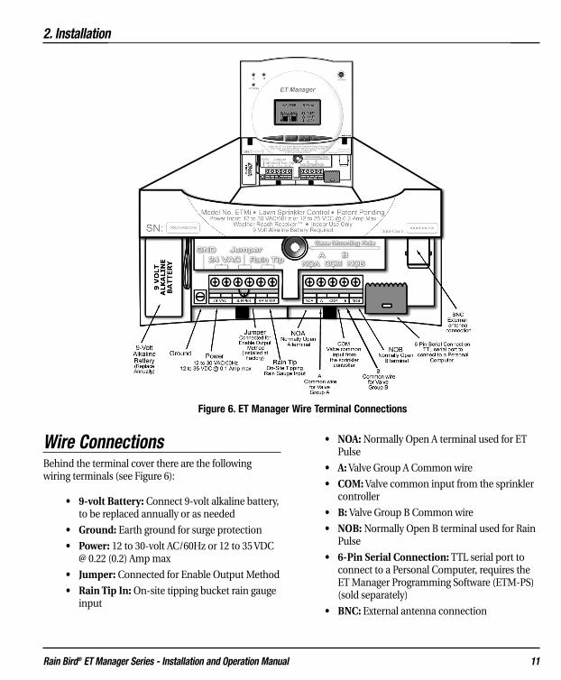
Wire ConnectionsBehind the terminal cover there are the followingwiring terminals (see Figure 6):
• 9-volt Battery: Connect 9-volt alkaline battery,to be replaced annually or as needed
• Ground: Earth ground for surge protection
• Power: 12 to 30-volt AC/60Hz or 12 to 35 VDC@ 0.22 (0.2) Amp max
• Jumper: Connected for Enable Output Method
• Rain Tip In: On-site tipping bucket rain gaugeinput
• NOA: Normally Open A terminal used for ETPulse
• A: Valve Group A Common wire
• COM: Valve common input from the sprinklercontroller
• B: Valve Group B Common wire
• NOB: Normally Open B terminal used for RainPulse
• 6-Pin Serial Connection: TTL serial port toconnect to a Personal Computer, requires theET Manager Programming Software (ETM-PS)(sold separately)
• BNC: External antenna connection
Figure 6. ET Manager Wire Terminal Connections

2. Installation
Rain Bird® ET Manager Series - Installation and Operation Manual 12
Wire Connection Guidelines• Strip approximately 1⁄4” insulation off the ends
of wires connected to the ET Manager, andstrip insulation off the ends of other wires asneeded.
• Use an appropriate screwdriver for all mount-ing.
• Use a thin blade screwdriver for all ET Managerwire terminal connections.
• Use appropriate screwdriver for all wire con-nections to sprinkler controller.
• Use proper wire gauges, 14-26 AWG for termi-nal connections, and 10-18 AWG for grounding.
• Use proper wire ties.
• Verify each wire connection is secure.
• Use a Volt-Ohm meter to test and verify com-mon wires and power source voltage.
WARNING: To prevent electrical shock make sure thepower supply is OFF before connecting wires to any ofthe devices. Electrical shock can cause severe injury ordeath.
GroundingConnect a 10, 12, 14 or 18-gauge ground wire to earthground. Strip approximately 1/4" insulation from theend of the ground wire and connect to the ET Managerground connection using a thin blade screwdriver. Givethe wire a gentle tug to verify it is secure.
GROUNDING IS ESSENTIAL for electrical surge pro-tection and personal protection.
Note: 10 AWG is preferred for grounding your ETManager.
PowerWARNING: To prevent electrical shock, damage to theET Manager, or damage to your sprinkler controller,make sure the power supply is OFF before connectingwires to any of the devices. Electrical shock can causesevere injury or death.
All electrical connections and wire runs must be madein accordance with local building codes.
The power requirement is 12 to 30-volts AC or 12 to 35-volts DC and draws a maximum 0.22 (0.2) Amp max.Power for the ET Manager can come from one of twosources:
Power Option 1The ET Manager can be connected to a 24-volt ACsource within the sprinkler controller. The currentdraw is 0.22 (0.2) Amps (less than one standard valvesolenoid). Check the sprinkler controller owner’s man-ual to verify that accessory devices can be poweredfrom the sprinkler controller power supply.
Connect a 14 or 18 AWG wire to the sprinkler controller24-volt AC power supply. Strip approximately 1⁄4" insu-lation from the ends of the power wires. Using a thinblade screwdriver, connect the wires to the ET Managerpower terminals labeled “24 VAC.” Give the wires a gen-tle tug to verify they are secure.
Power Option 2 Use a Rain Bird ETMi 120-volt AC Plug-in Transformer635640 (Model ETMi-TRAN). Using a thin blade screw-driver, attach the two orange wire ends of the trans-former to the 24-volt AC wire terminals on the ETManager wire terminal strip. If an adequate ground isnot connected, as described above, attach the greenground wire, to the ET Manager ground connectionusing a thin blade screwdriver. Give the wires a gentletug to verify they are secure. Plug power supply into a120-volt AC outlet.

2. Installation
Rain Bird® ET Manager Series - Installation and Operation Manual 13
Wiring DiagramsThe most common Output Method for the ET Manageris to interrupt the valve common output of a sprinklercontroller until watering is needed. This is referred toas the “Enable” Output Method. The ET Manager cansupport two Valve Groups, A and B. The valve commonfrom the sprinkler controller is wired into the ETManager and the Valve Groups A and B common wiresrun from the ET Manager to the sprinkler controlvalves. A separate common wire is required for eachvalve group. See Figure 7 for the Enable OutputMethod wiring diagram.
Note: The wiring diagrams for advanced OutputMethods are included in chapter 8.
Optional Rain GaugeRain measurements are provided from the remoteweather station operated by the WRSP. If site-specificrainfall measurements are desired, mount the optionalon-site tipping rain gauge (Model ETM-RG). Theoptional rain gauge will be used by the ET Manager inplace of the weather station rain information.
A local on-site rain gauge can be connected to the ETManager. The rain gauge must be a tipping gauge withan output measurement at either 0.01" or 1.0 mm pertip. The on-site rainfall value can be used in place ofthe rainfall value broadcast in the weather signal toprovide actual on-site rain data.
The Tipping Rain Gauge (Model ETM-RG) is an option-al rain gauge available from Rain Bird for use with theET Manager. The rain gauge contacts can be eithernormally open or normally closed.
Figure 7. ET Manager Terminal Connections - ET Enable Output Method
2. Installation
Rain Bird® ET Manager Series - Installation and Operation Manual 14
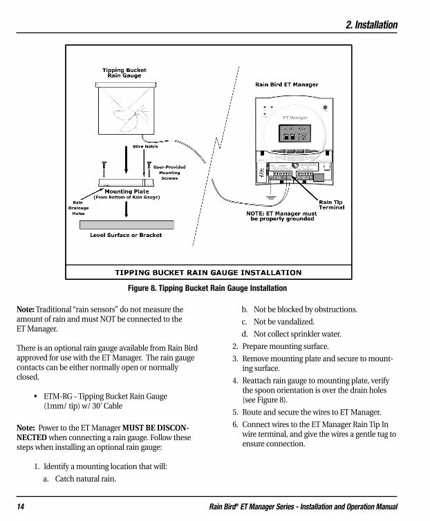
Note: Traditional “rain sensors” do not measure theamount of rain and must NOT be connected to the ET Manager.
There is an optional rain gauge available from Rain Birdapproved for use with the ET Manager. The rain gaugecontacts can be either normally open or normallyclosed.
• ETM-RG - Tipping Bucket Rain Gauge (1mm/ tip) w/ 30’ Cable
Note: Power to the ET Manager MUST BE DISCON-NECTED when connecting a rain gauge. Follow thesesteps when installing an optional rain gauge:
1. Identify a mounting location that will:
a. Catch natural rain.
b. Not be blocked by obstructions.
c. Not be vandalized.
d. Not collect sprinkler water.
2. Prepare mounting surface.
3. Remove mounting plate and secure to mount-ing surface.
4. Reattach rain gauge to mounting plate, verifythe spoon orientation is over the drain holes(see Figure 8).
5. Route and secure the wires to ET Manager.
6. Connect wires to the ET Manager Rain Tip Inwire terminal, and give the wires a gentle tug toensure connection.
Figure 8. Tipping Bucket Rain Gauge Installation

Optional External AntennaYour ET Manager contains a paging radio receiver witha built-in antenna. In most cases this antenna will besufficient. Conduct the Weather Signal Test from chap-ter 4, System Check. If the weather signal is regularlymissed by the built-in antenna, an external antennamay be connected and mounted in a different locationfor better reception. Use the Rain Bird ET ManagerRemote Antenna Kit (ETMi–ANT) to improve radioreception.
The ET Manager Remote Antenna Kit includes:
• Permanent Mount Antenna
• Mounting bracket
• Mounting screws
• 15 feet of RG8X cable with N style male con-nector and BNC male connector
• Self-fusing silicone sealing tape
Follow these steps when installing an optional externalantenna:
1. Identify a mounting location that will:
a. Allow antenna to be mounted vertically.
b. Improve radio reception.
2. Install the mounting bracket or prepare themounting surface.
3. Remove protective cap, mounting nut andwasher from the antenna.
4. Insert bottom of antenna into the mountingsurface.
5. Reattach mounting nut and washer to the bot-tom of the antenna.
2. Installation
Rain Bird® ET Manager Series - Installation and Operation Manual 15
Figure 9. External Antenna Installation

6. Attach the N style male connector to the bot-tom of the antenna.
7. Run the RG8X cable to the ET Manager, andconnect the BNC male connector to the ETManager BNC External Antenna Connection.
8. Seal each cable connection using the providedself-fusing silicone sealing tape.
9. Conduct the Weather Signal Test from chapter4, System Check. If the weather signal contin-ues to be regularly missed with proper installa-tion of the remote antenna, contact Rain Birdfor other options.
Note: Use of the ET Manager Remote Antenna Kit maynot assure reception in all areas due to local radio sig-nal conditions. For information on other options whenencountering poor radio signal conditions contact RainBird for additional options.
Note: If cable length is inadequate contact Rain Bird forcustom cable lengths.
Install BatteryA 9-volt alkaline battery should be installed in your ETManager to the 9-volt battery connection. The batterywill assure time keeping continues during a power out-age. It should be replaced annually or as needed.
If a power outage occurs, ET Manager control will beinterrupted. The sprinkler controller will activate sta-tion valves as programmed without ET Manager con-trol. The Valve Group A and B Indicator Lights will gooff. A status message will be displayed on the Homescreen indicating “No Power.” The weather signal willnot be received. If there are signals missed during apower outage, the ET Manager recognizes the missedsignal and estimates ET for the missed period.
If there is no power, the ET Manager can be pro-grammed using battery power. It takes several buttonpushes to “wakeup” the processor to allow menu navi-gation.
2. Installation
Rain Bird® ET Manager Series - Installation and Operation Manual 16

3. Programming
Rain Bird® ET Manager Series - Installation and Operation Manual 17
3. ProgrammingYour ET Manager operation requires programmingspecific settings. Most of the programmable settingsare site specific and are defined in chapter 6,Determining Programmable Settings. This chapter willallow you to program your ET Manager using generalsettings; refer to Appendix II for a table of general pro-grammable settings.
Programming OptionsThere are two programming options for an ETManager:
• Using the ET Manager Programming Software
• Manual Programming
Using the ET Manager Programming SoftwareThe ET Manager Programming Software (ETM-PS) is asoftware program that simplifies ET Manager program-ming. The ETM-PS allows you to connect your ETManager to a personal computer to perform several keyfunctions:
• Choose your WRSP and weather region frompull downs.
• Program all settings quickly and easily.
• Save programmable settings for future use.
• Use ET Manager Scheduler to help automati-cally set site specific settings for your ETManager.
• Access ET Manager diagnostic tools.
• Provides a printable report of programmed set-tings.
The ETM-PS software is sold separately. For ETManager Programming Software information, contactyour Rain Bird Distributor.
Note: If your ET Manager has been previously pro-grammed you should have received an ETM-PS report.This report is a summary of programmed settings. Youshould review these settings to verify they correspondto the actual site conditions.
Note: The yellow Attention Indicator Light may be onwhen power is connected to the ET Manager. Attentioncondition messages may be displayed on the Homescreen. Initially, the “Set Signal Provider Code” and “NoHistorical ET Data” messages may be displayed. Oncethese settings are programmed, the yellow AttentionIndicator Light will turn off and the attention messageswill disappear.
Manual Programming Manual programming allows you to program each set-ting on-site or in the field using the buttons and menusbuilt into the ET Manager. Manual programming canbe more time consuming than using the ET ManagerProgramming Software.
Manual Programming StepsManual programming can be broken into 4 key steps:
1. Data Source
2. Output Method
3. Site Specific Settings
4. Additional Settings
Note: Appendix I, ET Menu Structure, is available foreasy viewing of the ET Manager menus.
1. Data SourceSpecific settings must be programmed to obtain accessto the appropriate weather information. These settingsinclude:
• Weather Region
• Rain Source
• Elevation
• Signal Provider Code

3. Programming
Rain Bird® ET Manager Series - Installation and Operation Manual 18
Weather RegionMain Menu �Settings �System �Data Source
�Weather Region
The weather region number represents a weather sta-tion assigned by the WRSP. The weather region you setshould correspond to a weather station that closely rep-resents the location of the ET Manager. To obtain yourweather region number, contact your WRSP, the RainBird Distributor, your installation contractor, or go towww.rainbird.com/etmanager.
To set the weather region, navigate the menus toWeather Region, press À to move the cursor locationto the number and use the Œ or Õ to enter the weath-er region number.
Rain SourceMain Menu �Settings �System �Data Source �Rain Source
The rain source may come from:
• Signal: Use the rain value in the weather sig-nal from the selected weather region.
• Local (1mm per tip): Use an on-site tippingbucket rain gauge connected to the Rain Tip-interminal that measures rain with a 1mm per tipsignal (ETM-RG Tipping Rain Gauge).
• Local (0.01” per tip): Use an on-site tippingbucket rain gauge connected to the Rain Tip-interminal that measures rain with a 0.01” per tipsignal.
• Rain Region: Like the weather region number,a rain region number represents an area wherecustomers share data. Within an area, one on-site tipping bucket rain gauge is used to sharelocalized rain data among ET Manager cus-tomers, allowing for a more accurate represen-tation of local rain. Your WRSP broadcasts rainregion data.
To set the rain source, navigate the menus to RainSource, press À to enter into the Rain Source screen.Press À once more to change the • to the cursor, �.Use the Œ or Õ to select the rain source.
If the rain region is selected, press À to move the cur-sor location to the rain region number and use the Œor Õ to enter the rain region number.
ElevationMain Menu �Settings �System �Data Source �Elevation
Elevation above sea level is used when calculating ET.To enter a close estimation of your elevation, navigatethe menus to Elevation, press À to move the cursorlocation to the elevation, and use the Œ or Õ to setthe elevation.
Signal Provider CodeMain Menu �Settings �System �Data Source �Signal Provider Code
Your ET Manager must be programmed to receiveinformation from your specific WRSP. A Signal ProviderCode is unique for your WRSP and is necessary for yourET Manager to receive a weather signal. The code con-sists of 10 different numbers and these 10 numbers arelabeled A-J. To obtain this code, contact your WRSP, theRain Bird Distributor, your installation contractor, or goto www.rainbird.com/etmanager.
Navigate the Menus tothe Signal ProviderCode and press À toenter into the SignalProvider Code screen.Press Õ to move thecursor to “Yes” and press À. Use the Œ, Õ and Àbuttons to set the codes for A through J.

3. Programming
Rain Bird® ET Manager Series - Installation and Operation Manual 19
2. Output MethodTo accommodate almost any type of sprinkler con-troller, the ET Manager has four Output Methods:
Standard• Enable: This is the most common setting. A
sprinkler controller output is enabled to allowwatering only when needed.
Advanced• Enable A then B: This output operates the
same as the “Enable” method with one signifi-cant difference. There may be instances whenwatering needs to be spread over two days.The Enable A then B mode allows watering ononly one valve group per day, then alternates tothe other valve group on the next available day.
• ET and Rain Pulse: Advanced ET-based con-trollers can recognize ET and Rain pulseinputs.
• ET Pulse with Weather Interrupt: ET Pulsewith Weather Interrupt is similar to ET andRain Pulse with a second output acting as asensor interrupt to prevent watering if any oneof the three Weather Interrupt conditionsoccurs; rain, freezing conditions or high wind.
If not using Enable, review chapter 8, Advanced OutputMethods.
Output MethodMain Menu �Settings �System �Output Method
Navigate the menus to the Output Method. Press Àand you will see the current output method your ETManager is programmed to. Press À to see the list ofavailable Output Methods. A bullet • marks the currentselection. Press À again to move the �cursor to thelist. Use Œ or Õ to change the Output Method. Onceyou have selected the Output Method, use à to exitthe screen.
3. Site Specific SettingsSite specific settings are programmed to meet theneeds of your landscape and sprinkler system. FromSettings in the Main Menu access:
• Irrigation Control
• Weather Interrupt
Note: Refer to Appendix II for default settings, or tochapter 6, Determining Programmable Settings toestablish site specific ET Manager settings.
Irrigation ControlMain Menu �Settings �Irrigation Control
Irrigation control settings are based on site specificconditions. Plant type, soil type, sprinkler system capa-bilities, and available watering periods affect these set-tings:
• Irrigation Amount & Adjustments
• Water Window
• Available Watering Days
• Advanced Settings
Irrigation Amount and AdjustmentMain Menu �Settings �Irrigation Control �Irrigation Amount and Adj
The Irrigation Amount represents how many inches (ormm) of water is applied to your landscape for ValveGroup A and Valve Group B during each watering cycle.This amount of water evaporates from your landscapebefore the ET Manager will allow watering to occur.
The Landscape Adjustment Percentage is used to adjustfor site-specific landscape needs for Valve Group A andValve Group B. The Landscape Adjustment Percentageis applied to the calculated ET, and effects the currentMoisture Levels for Valve Groups A and B.

3. Programming
Rain Bird® ET Manager Series - Installation and Operation Manual 20
Refer to Determining Programmable Settings, chapter6, for more information on determining the values forthe Irrigation Amounts and Landscape AdjustmentPercentages.
Navigate to Irrigation Amount & Adjust, and press À.The cursor will be pointing to Irrigation Amount. Nowpress À once to position the cursor to the “A.” Use Œor Õ to choose between A and B. Press À when thecursor is in front of the valve group you would like toadjust. Use Œ or Õ to adjust the Irrigation Amount forA and B. Once the Irrigation Amount is adjusted, useà twice to get back to the Irrigation Amount field.
Note: If only one of the two Valve Groups is used, youcan “turn off” the remaining Valve Group by program-ming the Irrigation Amount to zero.
To set the Landscape Adjustment, press Õ placing thecursor in front of Landscape Adjustment. Press Àonce to position the cursor to the “A” and twice to posi-tion the cursor to the B value. Use Œ or Õ to adjustthe Landscape Adjust for A and B.
Water Window
Main Menu �Settings �Irrigation Control�Water Window
The ET Manager Water Window needs to be synchro-nized with the first sprinkler controller start time andthe length of all watering cycles. There are two WaterWindows used to manage the system:
• Automatic Window: The period of time thatthe ET Manager controls watering cycles basedon ET.
• Daily Window: An optional period whenwatering occurs as programmed in the sprin-kler controller as non-ET based wateringschedules not controlled by the ET Manager.During this period of time, watering will not becontrolled by the ET Manager.
To avoid overlapping between the Automatic and DailyWindows, the ET Manager restricts at least one hourseparation between the beginning and ending of eachWater Window. If there is no Daily Window pro-grammed, the Daily Window time range will be dis-played as “Off.”
There are two steps to program the Automatic Window:
1. Program thebeginning of theAutomaticWindow. Theposition of thecursor will be atAutomatic Window. Press À to move thecursor to the opening time of the AutomaticWindow. Use Œ or Õ to set the opening time,synchronized to the first start time pro-grammed in the sprinkler controller.
2. Press À to pro-gram the end ofthe AutomaticWindow. Use Œor Õ to set thelength of time forthe Automatic Window. The AutomaticWindow should be the total length of time ittakes to complete all watering cycles. When fin-ished, press à twice to exit from the Automatic Window.
The steps to programming the Daily Window are simi-lar to programming the Automatic Window.
Note: If you do not wantto program a DailyWindow, set your starttime and ending time tothe same hour, and OFFwill appear under theDaily Window.
Note: The display changes from the closing time to alength of time when programming the Water Windowsettings. For example, if the Automatic Window is set

3. Programming
Rain Bird® ET Manager Series - Installation and Operation Manual 21
from 10:00 pm to 8:00 am, once you press à your ETManager will display 10:00 pm for 10 hours.
Note: Use a separate sprinkler controller program fornon-ET based watering schedules.
Available Watering DaysMain Menu �Settings �Irrigation Control �Available Watering Days
The days available for watering can be programmed inyour ET Manager or your sprinkler controller. TypicallyAvailable Watering Days are set to “all” or everyday. Thedays available for watering could be limited because ofscheduled maintenance, facility use, or local wateringrestrictions.
To program the Available Days go to the Available Daysscreen, press À, and use Œ or Õ to position the cur-sor on the selected option. Watering days can be set to:
• All: Water on any day of the week.
• Even: Water only on even days of the week.
• Odd: Water only on odd days of the week.
• Odd Off 31: Water only on odd days of theweek, and watering will not occur on the 31st
of the month.
• Custom: Theuser can limit thedays of the weekthat watering canoccur. Whenchoosing custom,press À to advance to the next screen. Onthese screens selected days can be turned “On”or “Off.” Use the arrow keys to select thedesired day, and then use À to move thecursor to the “On” or “Off” setting. Use Œ orÕ to toggle between “On” or “Off.” Use à togo back. Repeat for all days, advance to thenext screen and continue until all days areprogrammed.
Look-Ahead Feature: If Available Days is not pro-grammed to “All” and specific days are not available,the ET Manager looks ahead to determine if wateringshould occur even though the Moisture Level has notreached “0.”
When the Automatic Window opens, it checks to see ifthe next watering day is an available water day. If thenext day is a “No Water Day” and it determines thatwatering would most likely occur on that day, wateringwill be enabled. The ET Manager looks at the currentMoisture Level and current ET and allows watering,even if the Moisture Level has not reached “0.”
Note: When restricting available watering days, theWater Window must begin and end either before mid-night, or after midnight. If your Water Window is pro-grammed to run through midnight, you must set avail-able days to all in the ET Manager. You can still pro-gram off days by turning days off on your sprinkler con-troller. A sensor built into your ET Manager will recog-nize off days scheduled into your sprinkler controller.The Look-Ahead Feature will not function.
Note: Available days can affect the Daily Window set-ting. If days are restricted, the Daily Window does notallow watering on the restricted day.
Advanced SettingsMain Menu �Settings �Irrigation Control �Advanced Settings
The Advanced Settings menu provides additional con-trol features using the ET Manager. These settingsinclude:
• Effective Rain
• Signal Crop Coefficient
• Wind Adjust %
• Historical ET

3. Programming
Rain Bird® ET Manager Series - Installation and Operation Manual 22
Effective Rain Settings
Main Menu �Settings �Irrigation Control �Advanced Settings �Effective Rain Settings
Not all rainfall measured is considered effective rain.Rain that falls too quickly will run off before reachingthe root zone, and rain that falls when the soil is com-pletely saturated will run off as well. The Effective Rainsettings include:
• Max Hourly Rain: The Maximum Hourly Rainis the maximum amount of rain that will beaccepted each hour in the soil moisture level.
• Saturation Allowance for A and B: TheSaturation Allowance is equal to the amount ofrain it takes to saturate the soil after satisfyingthe Irrigation Amount and before runoffoccurs.
Navigate the menus to the Advanced Settings screen,and press À on Effective Rain Settings screen. The �will be at Max Hourly Rain, press À to move the cur-sor to the Max Hourly Rain value, and use Œ or Õ toadjust the value. Use à to go back to set theSaturation Allowance for A and B. Once the � is locatedat Saturation Allowance, press À once to move thecursor to A and twice to B. Use Œ or Õ to adjust thesevalues.
Signal Crop Coefficient
Main Menu �Settings �Irrigation Control �Advanced Settings �Signal Crop Coefficient
The WRSP includes a Signal Crop Coefficient percentagein the weather signal. A Signal Crop Coefficient (Kc)adjusts ET to a specific crop and can change over the yeardue to seasonal conditions (ETos x Kc = ETc).
You can choose to use or ignore the Signal CropCoefficient. After navigating to the Signal CropCoefficient screen, press À to change the • to � anduse Œ or Õ to “Use” or “Ignore” the crop coefficientincluded in the weather signal. In most cases this is setto “Use.”
Note: You can view the Signal Crop Coefficient percent-age from:
Main Menu �Irrigation Status �Evaporation (ET) �Signal Kc
Wind Adjust
Main Menu �Settings �Irrigation Control �Advanced Settings �Wind Adjust %
The wind speed measurement included in the weathersignal can be scaled by a percentage to compensate forvariations in prevailing conditions. Press À to movethe cursor to the percentage and use Œ or Õ to adjustthe value.
Historical ET
Main Menu �Settings �Irrigation Control �Advanced Settings �Historical ET
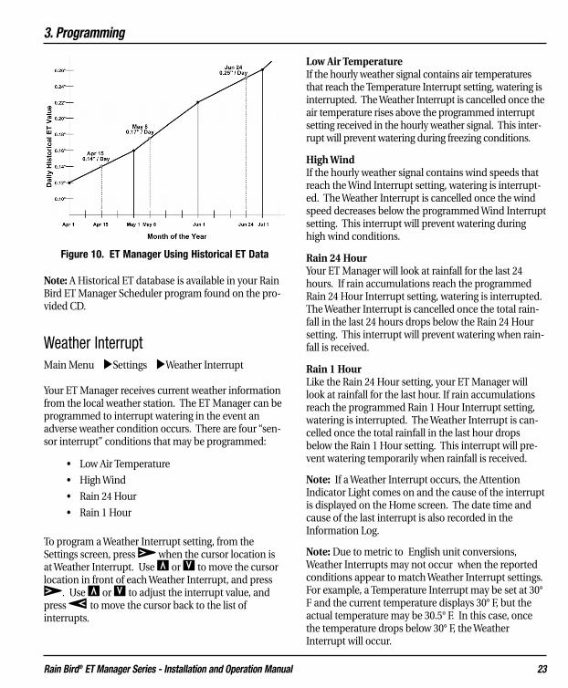
The ET Manager can be set to operate using historicalET data, instead of the weather signal data. If a prob-lem occurs and the ET Manager is not receiving theweather signal, it will continue to operate using histori-cal ET data as a default ET. This setting represents anaverage daily ET for each month. To obtain the averagedaily historical ET for your area, go towww.rainbird.com/etmanager and download yourWeather Reach Signal Provider Information Sheet.
From the Historical ETscreen, the cursor locationwill be at January. To enterJanuary daily ET average,press À moving the cur-sor location to the ET value.Use Œ or Õ to adjust the ET value, and press à tomove the cursor back to the list of months. Scroll downto the next month and repeat the process for each month.
Your ET Manager uses the programmed daily historicalET at the first of each month, and then looks at the nextmonth value to make an ET curve to determine historicET values for each day of the month (see Figure 10).
3. Programming
Rain Bird® ET Manager Series - Installation and Operation Manual 23
Note: A Historical ET database is available in your RainBird ET Manager Scheduler program found on the pro-vided CD.
Weather InterruptMain Menu �Settings �Weather Interrupt
Your ET Manager receives current weather informationfrom the local weather station. The ET Manager can beprogrammed to interrupt watering in the event anadverse weather condition occurs. There are four “sen-sor interrupt” conditions that may be programmed:
• Low Air Temperature
• High Wind
• Rain 24 Hour
• Rain 1 Hour
To program a Weather Interrupt setting, from theSettings screen, press À when the cursor location isat Weather Interrupt. Use Œ or Õ to move the cursorlocation in front of each Weather Interrupt, and pressÀ. Use Œ or Õ to adjust the interrupt value, andpress à to move the cursor back to the list of interrupts.
Low Air TemperatureIf the hourly weather signal contains air temperaturesthat reach the Temperature Interrupt setting, watering isinterrupted. The Weather Interrupt is cancelled once theair temperature rises above the programmed interruptsetting received in the hourly weather signal. This inter-rupt will prevent watering during freezing conditions.
High WindIf the hourly weather signal contains wind speeds thatreach the Wind Interrupt setting, watering is interrupt-ed. The Weather Interrupt is cancelled once the windspeed decreases below the programmed Wind Interruptsetting. This interrupt will prevent watering duringhigh wind conditions.
Rain 24 HourYour ET Manager will look at rainfall for the last 24hours. If rain accumulations reach the programmedRain 24 Hour Interrupt setting, watering is interrupted.The Weather Interrupt is cancelled once the total rain-fall in the last 24 hours drops below the Rain 24 Hoursetting. This interrupt will prevent watering when rain-fall is received.
Rain 1 HourLike the Rain 24 Hour setting, your ET Manager willlook at rainfall for the last hour. If rain accumulationsreach the programmed Rain 1 Hour Interrupt setting,watering is interrupted. The Weather Interrupt is can-celled once the total rainfall in the last hour dropsbelow the Rain 1 Hour setting. This interrupt will pre-vent watering temporarily when rainfall is received.
Note: If a Weather Interrupt occurs, the AttentionIndicator Light comes on and the cause of the interruptis displayed on the Home screen. The date time andcause of the last interrupt is also recorded in theInformation Log.
Note: Due to metric to English unit conversions,Weather Interrupts may not occur when the reportedconditions appear to match Weather Interrupt settings.For example, a Temperature Interrupt may be set at 30°F and the current temperature displays 30° F, but theactual temperature may be 30.5° F. In this case, oncethe temperature drops below 30° F, the WeatherInterrupt will occur.
Figure 10. ET Manager Using Historical ET Data

3. Programming
4. Additional Settings and Options
Additional settings are programmed to facilitate generaluse of your ET Manager. From Settings in the MainMenu access:
• System Options
• Date and Time
System OptionsMain Menu �Settings �Systems �Options
There are four Options:
• Units
• Password
• Clear Data
• Defaults
Units
Main Menu �Settings �Systems �Options �Units
ET Manager can operate in either English units or met-ric units. To change navigate the menus to units, anduse the Œ or Õ buttons to make the change.
Password
Main Menu �Settings �Systems �Options �Password
To limit access to the Settings menu a password may beset. To program a password, use Œ or Õ to select thedesired numeric password. The value can be set from 1to 255, or none. Once set, the password must be usedto gain access to the Settings menus. A password set-ting of “None” disables password protection. None isfound by scrolling one down from the numeric value 1.
Clear Data
Main Menu �Settings �Systems �Options �Clear Data
If it becomes necessary, you may clear all records storedin the ET Manager. Clearing Data will not change set-tings, but will erase all weather information, the currenttime and date, and will automatically set your MoistureLevels to 0, enabling watering.
To clear data, navigate the menus to the Clear Datascreen, use the Õ to select “Yes.” Push the À but-ton to confirm your decision.
Defaults
Main Menu �Settings �Systems �Options �Defaults
There are two options from the Defaults menu:
• Save Defaults
• Restore Defaults
Save Defaults
To save the current ET Manager settings as defaults,select Save Defaults then press À. You will then needto push Õ so the cursor is on “Yes” and push À toconfirm your decision.
The defaults settings that can be saved are:
• Settings
• Irrigation Control
• Irrigation Amount and LandscapeAdjustment % for Valve Group A and B
• Water Window
• Automatic
• Daily
• Available Watering Days
• All, Odd, Odd with 31st Off, Even,Custom Days
• Advanced Setting
• Effective Rain Settings
Rain Bird® ET Manager Series - Installation and Operation Manual 24
3. Programming
Rain Bird® ET Manager Series - Installation and Operation Manual 25
• Maximum Hourly Rain
• Saturation Allowance A
• Saturation Allowance B
• Signal Crop Coefficient
• Wind Adjust %
• Historical ET
• January - December
• System
• Data Source
• Weather Region
• Rain Source
• Elevation
• Options
• Units
• Output Method
• Enable
• Enable A then B
• ET and Rain Pulse
• Rain and ET Pulse Duration
• Pulse per minute
• ET Pulse with Interrupt
• ET Pulse Duration
• Pulse per minute
• Weather Interrupt
• Low Temperature
• High Wind
• Rain 24 Hour
• Rain 1 Hour
Restore Defaults
To restore defaults, select Restore Defaults then pressÀ. You will then need to push Õ so the cursor is on“Yes.” Push À to confirm your decision.
Date & TimeMain Menu �Settings �Date and Time
The Date and Time are updated from the weather sig-nal sent by your WRSP. The only occasion you shouldneed to program the date and time is in the event thatno weather signal is available and the device is operat-ing in the Historical ET Control Mode.
Year: Set the current year.Month: Set the current month.Day: Set the current day.Time: Set the current time.
Programming the SprinklerControllerYour sprinkler controller will need to be programmed towork with your ET Manager. Specifically program:
• Watering Days
• Cycle Start Times
• Station Run Times
• Non-ET Based Watering Schedules
Note: Appendix VII, Sprinkler Controller ProgrammingWorksheet, is available as a sprinkler controller pro-gramming aid.
Watering DaysThe ET Manager controls the days of watering.Watering days will only occur as needed, based onweather information. The sprinkler controller shouldbe programmed to water every day.
Note: If you choose to program the sprinkler controllerwith specific days off, then the ET Manager uses a sen-sor to detect a no water day and will continue to allowwatering the next available day.

3. Programming
Rain Bird® ET Manager Series - Installation and Operation Manual 26
Cycle Start TimesYour ET Manager does NOT start a watering cycle; it“enables” or allows the sprinkler controller to activatethe valves when watering is needed. Cycle start timesshould be programmed into your sprinkler controller tomeet the needs of the site. You may program multiplestart times into your sprinkler controller. The ETManager will allow all cycles to operate.
Station Run TimesStation run times must be set in your sprinkler con-troller so the valves will apply the correct amount ofwater to your landscape. Your ET Manager “enables”watering cycles to refill the plant root zone by applyingthe Irrigation Amount. The station run times is thetime it takes for sprinklers to apply the IrrigationAmount and is based on how fast the sprinklers applywater (precipitation rate). Table 1 can serve as a guideto determining station run times, given the precipita-tion rate and the Irrigation Amount.
Refer to Appendix V for information on calculating theprecipitation rate and station run times.
Note: Station run times may need to be adjusted basedon the uniformity of the sprinkler system.
Note: The total station run time may need to be splitinto several cycles to allow the water to soak betweencycles.
Non-ET Based Watering Schedules
If stations need to operate as programmed in the sprin-kler controller, and NOT managed by your ET Manager,the ET Manager can allow a period of time for thesprinkler controller to water as programmed in theDaily Window; found in the Water Window submenu.Use a separate sprinkler controller program for non-ETbased watering schedules.
Irrigation Amount (inches)0.35" 0.50" 0.65"
PrecipitationRate (inches
per hour) Station Run Times(minutes)
2.00 11 15 201.75 12 17 221.50 14 20 261.25 17 24 311.00 21 30 390.90 23 33 430.80 26 38 490.70 30 43 560.60 35 50 650.50 42 60 780.40 53 75 98
Typically Rotors
Typically Spray Heads
Table 1. Minutes of Station Run Times

4. System Check
Rain Bird® ET Manager Series - Installation and Operation Manual 27
4. System CheckNow that your ET Manager is installed and pro-grammed, ensure successful operation by following theguidelines outlined in this chapter to verify that instal-lation and programming is correct. To ensure the sys-tem check is completed properly, Refer to AppendixVIII: ET Manager Installation Checklist.
System CheckVerify these settings or tests after installation and pro-gramming are complete:
• Control Mode
• Weather Signal Test
• Valve Control Test
• Water Window Settings
• Initial Moisture Level
Control Mode
Main Menu �Control Mode
There are three operating or Control Modes plus a tem-porary Override mode. The three Control Modes are:
• Automatic (normal operating mode)
• Historical ET
• Disabled
AutomaticAutomatic control is the standard mode setting. Inthis mode all automatic functions are active and yourET Manager will operate as programmed. It will utilizethe incoming weather signal to manage sprinkler con-trol.
To set the ET Manager in Automatic mode, navigate themenus to the Control Mode screen.A bullet • will be in front of the mode the ET Manageris currently set in. If the cursor � is not in front of“Control Mode”, use Œ or Õ to move the location of
the cursor to Control Mode. Press À to move thecursor location to the operating mode. Use Œ or Õ toposition the cursor in front of “Automatic,” and pressà to move the cursor back to Control Mode. The •will be at “Automatic.”
Historical ETWhen in Historical ET Control Mode, the ET Manageruses programmed daily ET averages for each month ofthe year to manage sprinkler control. In the HistoricalET mode information from the weather signal isignored. If an on-site rain gauge is installed with yourET Manager, the rain data recorded will adjust sprinklercontrol.
The Historical ET Control Mode is provided for 3 rea-sons:
1. In the event that the weather signal is tem-porarily not available, the ET Manager willoperate based on Historical ET information asdefault backup.
2. There may be situations when you need a spe-cific watering schedule. For example a seededlawn may need daily watering. If needed, youcan set the Control Mode to Historical ET andprogram the desired daily ET value.
3. Some locations may not currently receive aweather signal. An ET Manager can still beused to control sprinkler schedules based onHistorical ET. Under these conditions an on-site rain gauge will provide improved real-timecontrol of watering schedules.
DisabledThe ET Manager can be disabled. All automatic func-tions are suspended. The weather signal will continueto be received and logged, ET will be calculated, but alloutputs are disabled and the Valve Group A and BIndicator Lights will go off. The ET Manager will notinterrupt the sprinkler controller and the sprinkler sys-tem will operate as if the ET Manager was not there.
Note: If your ET Manager is set back to Automatic

4. System Check
Rain Bird® ET Manager Series - Installation and Operation Manual 28
mode after being in Disabled mode for an extendedperiod of time, verify the current moisture level todetermine when the first automatic watering cycleshould occur.
OverrideIf you need to manually turn on valves and the ETManager is interrupting the output of the sprinkler con-troller (Valve Group Indicator Light(s) are red), pressthe Override button to enable sprinkling for one hour.If more time is needed, press the Override button toincrease override in one-hour increments.
The ET Manager can also be set to the Override modefrom the Control Mode screen. Use Œ in the OverrideControl Mode screen to set the number of hours theOverride mode should run. After the override time haselapsed, your ET Manager will resume normal opera-tion. If you want to cancel the Override mode, press Õuntil “Hours” is set to zero.
Weather Signal TestThe ET Manager uses a paging radio receiver with abuilt-in antenna to receive the weather signal. In mostcases, this antenna is reliable.
Follow these steps to verify your ET Manager receivesweather signals:
1. ET Manager must be powered using a 24-voltAC power source.
2. Navigate the menus to the Weather Signalscreen.
Main Menu �Information Log �Weather Signal
3. Verify the weather signal is “Detected,” thismay take up to two minutes.
4. From the Weather Signal screen, monitor theTest Counter. The Test Counter registers everysignal received increasing from 1 to 255 counts.
Note: If 255 signals are received and counted, theTest Counter will reset to 0.
5. If the weather signal is “Not Detected” after twominutes, verify the Signal Provider Code is pro-grammed correctly. If the Signal Provider Codeis programmed incorrectly, use the Œ, Õ andÀ buttons to set the codes for A through J.
Main Menu �Settings �System �Data Source �Signal Provider Code
Note: To obtain your Signal Provider Code, contactyour WRSP, the Rain Bird Distributor, your installa-tion contractor, or go towww.rainbird.com/etmanager. See chapter 3,Programming, for more information on the SignalProvider Code.
6. Once the Signal Provider Code is confirmedcorrect, press À to reset.
Main Menu �Information Log �Weather Signal �Reset
7. If the weather signal becomes “Detected,”monitor the signal Accuracy percentage overseveral days.
Main Menu �Information Log �Weather Signal �Accuracy
8. If the signal remains “Not Detected” after com-pleting the steps above, try a different installa-tion location or an optional external antenna.
Note: Because of the nature of radio transmission,strength of the paging signal may vary dependingupon your location. An external antenna may beused in some areas to eliminate signal weakness-es. See chapter 2, Installation, for more informa-tion on optional external antennas.
Note: The Reset command also clears the testcounter.
4. System Check
Rain Bird® ET Manager Series - Installation and Operation Manual 29
Valve Control Test When using Enable Output Method, your ET Managercontrols the output of the sprinkler controller. Followthese steps to verify your ET Manager interrupts thestations on each Valve Group, A and B:
Note: To complete the Valve Control Test, theAutomatic Window or Daily Window must beclosed. If a status message appears on the Homescreen with either “Automatic Window Open” or“Daily Window Open” temporarily close theAutomatic or Daily Window by changing the WaterWindow settings outside the current time dis-played on the Home screen.
1. On initial startup the Valve Group A and BIndicator Lights are green, indicating wateringis not interrupted. If the lights are red, adjustthe Current Moisture Level for A and B belowzero.
Main Menu �Irrigation Status �A and BMoisture Level �Current Level
2. Manually turn on each station with your sprin-kler controller and visually check that all sta-tions operate.
3. Adjust the Current Moisture Level for ValveGroup A above zero. The Valve Group AIndicator Light will turn red and interrupt thewatering on Valve Group A.
Main Menu �Irrigation Status �A and BMoisture Level �Current Level
4. Manually turn on each station with your sprin-kler controller and visually check that ValveGroup A stations do not operate and ValveGroup B stations still come on.
5. Reverse the Moisture Level settings for A and B,so that the Valve Group B Indicator Light is redand that the Valve Group A Indicator Light isgreen. Then repeat step 4 for to verify that
Valve Group B stations do not come on, whileValve Group A stations operate.
6. Set both Moisture Levels back to the desiredlevel, a setting of zero will allow the next water-ing cycle to occur.
Water Window SettingsVerify the Water Window settings were set correctly inyour ET Manager. The Water Window settings consistof the Automatic and Daily Windows, where theAutomatic Window is the period of time that the ETManager controls watering cycles based on ET and theDaily Window is an optional period of time whenwatering can occur as programmed in the sprinklercontroller, and is not controlled by your ET Manager.
These Water Window settings should be checked toconfirm that they correspond with the start times andrun times programmed in the sprinkler controller. Youshould also verify that the current time is set correctlyon the sprinkler controller.
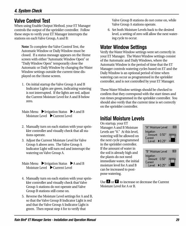
Initial Moisture LevelsOn startup, your ETManager A and B MoistureLevels are “0.” At this level,watering will be allowed onthe next cycle programmedin the sprinkler controller.If the amount of water inthe soil is already high andthe plants do not needimmediate water, the initialmoisture level for A and Bcan be increased to post-pone watering.
Use Œ or Õ to increase or decrease the CurrentMoisture Level for A or B.

5. Routine Operations
Rain Bird® ET Manager Series - Installation and Operation Manual 30
5. Routine OperationWhen installed and programmed properly, the ETManager will automatically provide ET based manage-ment to your sprinkler system. In most cases, program-mable settings should not need to be changed. Routineoperation may include viewing and using:
• Weather Information: Current weather infor-mation is displayed. A two-week log of condi-tions is displayed graphically.
• Irrigation Status: Current moisture levels andirrigation settings are easily monitored.
• Information Log: Key events are recorded inthe information log.
• Override: If manual watering is needed, pressoverride to temporarily allow watering.
• Status Messages: The Home screen reportscurrent activity.
• Attention Messages: If the Attention IndicatorLight is on, the Status line will display impor-tant information.
Weather InformationCurrent weather information can be viewed in your ETManager. The weather information is measured at aselected weather station and hourly data is broadcast inthe weather signal to your ET Manager. The data is ascurrent as the last broadcast. If a local rain gauge or rainregion is used, rainfall amounts are recorded immedi-ately. The following weather information can be viewedin the weather summary screen:
Main Menu �Weather Info
• Rain
• Temperature
• Wind
• Humidity
Rain Main Menu �Weather Info �Rain
The rain screen displays rainfall values measured by theselected rain source. The following detail is displayed:
• Last Hour: Total measured rainfall in the lasthour.
• Last 24 Hours: Total measured rainfall in thelast 24 hours.
• Last 7 Days: Total measured rainfall in the last7 days.
• Graph: Press À to view a graph that repre-sents the recorded rainfall over the last twoweeks.
TemperatureMain Menu �Weather Info �Temperature
Temperature values included in the weather signal arerecorded hourly averages. The following detail is dis-played:
• Current: Hourly average air temperature fromthe latest recorded broadcast.
• High Today: The day’s highest air temperaturerecorded broadcast since midnight.
• Low Today: The day’s lowest air temperaturerecorded broadcast since midnight.
• Graph: Press À to view a graph that displaysthe recorded high and low temperatures overthe last two weeks.
WindMain Menu �Weather Info �Wind
Wind values included in the weather signal are record-ed hourly averages. Peak wind velocity is not displayed.The following detail is displayed:
• Current: Hourly average wind speed from thelatest recorded broadcast.

5. Routine Operations
Rain Bird® ET Manager Series - Installation and Operation Manual 31
• High Today: The day’s highest average windspeed recorded broadcast since midnight.
• Low Today: The day’s lowest average windspeed recorded broadcast since midnight.
• Graph: Press À to view the graph. Thegraph displays the recorded average windspeed over the last two weeks.
HumidityMain Menu �Weather Info �Humidity
Humidity values included in the weather signal arerecorded hourly averages. The following detail is dis-played:
• Current: Hourly average humidity percentagefrom the latest recorded broadcast.
• High Today: The day’s highest humidityrecorded broadcast since midnight.
• Low Today: The day’s lowest humidity record-ed broadcast since midnight.
• Graph: Press À to view a graph that repre-sents the recorded humidity over the last twoweeks.
Note: If no weather data has been stored in the ETManager, each graph screen will be blank.
Irrigation StatusThe most important information regarding the controlof your sprinkler system can be seen in the twoMoisture Level screens located in the Irrigation Statusmenu. In the Irrigation Status menu, ET, and rain infor-mation can also be viewed.
A (or B) Moisture LevelMoisture is depleted from the soil due to evaporation.Rain and water from the sprinkler system replaces thiswater. Your ET Manager uses this information to com-pute the current moisture level. When the MoistureLevel reaches “0” watering is enabled and the sprinklercontroller is allowed to water. Zero does not mean thesoil is completely dry; zero means that the amount ofwater allowed to be depleted has evaporated and it istime to water.
There are three factors used to compute the CurrentMoisture Level:
• ET: Water evaporates and transpires from thelandscape based on current weather condi-tions.
• Effective Rain: Rain is measured using theselected rain source. Accepted rainfall is limit-ed by the Effective Rain settings.
• Irrigation: Watering from your sprinkler sys-tem.
The formula to calculate the Current Moisture Level is:
Current Moisture Level = Last Moisture Level – ET +Effective Rain + Irrigation, where:
• Last Moisture Level = Moisture Level from theprior hour
• ET = ET measurements adjusted by theLandscape Adjustment percentage
• Effective Rain = Limited due to programmedMax Hourly Rain and Saturation Allowance
• Irrigation = Irrigation Amount setting oncewatering is detected

5. Routine Operations
Rain Bird® ET Manager Series - Installation and Operation Manual 32
Saturation
Rain
Irrigation
Table 2 represents an example of how the moisturelevel can change over time. Notice that on the day theMoisture Level reaches “0,” irrigation occurs to refillthe soil.
Table 2. Moisture Level Chart
Table 2 demonstrates that ET causes water to be lostfrom the soil moisture level. It is subtracted from theprior soil moisture level and effective rain or sprinklingadds to the soil moisture level.
6/1/2004 Soil Moisture Level = 0.23” 6/2/2004 - ET = 0.05”
0.18”+ Effective Rain = 0.20”
6/2/2004 Soil Moisture Level = 0.38”
Once daily accumulation of ET causes the soil moisturebalance to reach zero or a less than zero balance (nega-tive balance), the ET Manager will allow sprinkling tooccur.
6/11/2004 Soil Moisture Level = 0.16” 6/12/2004 - ET = 0.18”
-0.02”+ Irrigation = 0.50”
6/12/2004 Soil Moisture Level = 0.48”
This same information can be displayed graphically inFigure 11.
Figure 11. Soil Moisture Level
To keep plants healthy, proper landscape water man-agement will keep soil moisture at optimum levels.Saturated soil starves the roots of essential oxygen. Thesoil must be allowed to dry out, not to a wilt point, butenough to get air to the roots. To promote a deephealthy root system, best horticultural practices recom-mend deep, less frequent watering. Watering frequencyshould be managed in response to changing weatherconditions and rainfall. The ET Manager monitorsevaporation and manages your sprinkler system allow-ing watering only when needed.
(Rain delays watering)
(Watering occurs)

5. Routine Operations
Rain Bird® ET Manager Series - Installation and Operation Manual 33
Access Moisture Levels for A or B
Main Menu �Irrigation Status �A (or B) Moisture Level
The following information is shown on this screen:
• Irrigation Amount: The amount of waterapplied by the sprinkler system to refill the soilmoisture reservoir.
• Current Level: The current calculated mois-ture level for A (or B).
• Moisture Level Graphic: On the right thegraphic represents the current moisture level.When the “soil” is “empty” it is time to water.Watering is not needed until the Moisture levelreaches zero.
• Graph: Press À to display a graph that rep-resents the soil moisture level over the last twoweeks.
Adjusting the Current Level: There may be circum-stances when the current level needs to be adjusted,like during Valve Group testing, delaying watering, ortroubleshooting. Use Œ or Õ to make the change.Increasing this value may delay watering. By taking thevalue to zero watering will be allowed on the nextscheduled cycle.
Rain Main Menu �Weather Info �Rain
The rain screen displays rainfall values measured fromthe selected rain source. The ET Manager stores four-teen days of information, which can be viewed in thegraph. The following detail is displayed:
• Last Hour: Total measured rainfall in the lasthour recorded broadcast.
• Last 24 Hours: Total measured rainfall in thelast 24 hours.
• Last 7 Days: Total measured rainfall in the last7 days.
• Graph: Press À to view the rain graph forthe last two weeks.
Evaporation (ET)Main Menu �Irrigation Status �ET
The ET screen displays the ET calculated by the ETManager based on current settings and the weatherconditions included in the weather signal. The ETManager stores fourteen days of information, whichcan be viewed in the graph. The following detail is dis-played:
• Last Hour: ET based on data in the last hourrecorded broadcast.
• Last 24 Hours: Total ET in the last 24 hours.
• Last 7 Days: Total ET in the last 7 days.
• Signal Kc: Signal crop coefficient percentageincluded in the weather signal.
• Graph: Press À to view the ET graph for thelast two weeks.
Note: In the Automatic Control Mode, when weathersignals are missed the ET Manager will automaticallycalculate ET for the missed signals. If weather signalsare not received for more than a day then the ETManager will calculate ET based on weather data fromthe last 7 days. If there is no weather signal receivedfor more than a week, the mode automatically uses thepre-programmed Historical ET values. Even though sig-nals are missed, the ET Manager will continue to oper-ate. When this occurs, the ET Manager will report thelast hour of ET as 0.00".
Note: In the Historical Control Mode, the ET Managerwill report the last hour of ET as 0.00".
Information LogThe Information Log menu helps you know whatevents have occurred. Watering over the season isrecorded, weather interrupts, and signal status can helpyou monitor the activity of your ET Manager. TheInformation Log includes:
• A Irrigation Log
• B Irrigation Log
• Last Interrupt
• Weather Signal

5. Routine Operations
Rain Bird® ET Manager Series - Installation and Operation Manual 34
A or B Irrigation LogMain Menu �Information Log �A (or B) Irrigation Log
• Last: Date and time of the last detectedAutomatic Window watering for Valve Group“A” or “B.”
• Days Watered: Number of days the ETManager has allowed watering for Valve Group“A” or “B.” This accumulates “since” the dateindicated on this screen.
• Total Water: The estimated total amount ofwatering for Valve Group “A” or “B.” This accu-mulates “since” the date indicated on thisscreen.
• Since: The Days Watered and Total Inches ofwater applied are calculated since the date indi-cated.
• Graph: With the �cursor pointing to theGraph icon, press À to view the two-weeksoil moisture graph.
• Clear: Position the �cursor to the Clearoption to reset the “Since” date. This will alsoreset the Days Watered and Total Water to zero.Clearing will also reset the since date to thecurrent date.
Last Interrupt Main Menu �Information Log �Last Interrupt
The Last Interrupt displays the cause, date, and time ofthe last weather interrupt.
Weather SignalMain Menu �Information Log �Weather Signal
The Weather Signal screen displays:
• Last: The date and time of the last recordedweather signal.
• Accuracy: The ET Manager looks at the lasttwo weeks of weather signals and reports the
accuracy of the weather signal. An accuracylevel less than 65% will create an Attentioncondition. The cause should be identified andcorrected. If a weather signal is missed the ETManager adjusts automatically.
• Signal: The weather signal is reported aseither “Detected” or “Not Detected.” If theweather signal is not detected press the À atthe Reset option to confirm this status. Signaldetection can take up to two minutes. If thiscondition persists contact your installer or RainBird Authorized Distributor.
• Test Counter: The test counter reports all sig-nals received by the ET Manager. The frequen-cy and number of signals is controlled by theWRSP. The test counter is a diagnostic tool tofurther test the signal reception of the ETManager. The test counter accumulates sig-nals, and is cleared by resetting the signal. TheTest Counter registers every signal receivedincreasing from 1 to 255 counts, and resets tozero once 255 is reached.
Status MessagesDuring normal operation the ET Manager is perform-ing programmed functions. There are conditions thatyour ET Manager reports. On the Home screen the sec-ond line displays current status messages. When morethan one message needs to be displayed the messageswill alternate every few seconds.
Note: “Attention” messages are also displayed on thesame Home screen line.
The following is an explanation of the status messagesdisplayed:
• Automatic Window Open
• Daily Window Open
• Disabled Mode
• No Water Day
• Hour Manual Override
• No Power

5. Routine Operations
Rain Bird® ET Manager Series - Installation and Operation Manual 35
Automatic Window OpenThe Automatic Window is a period of time pro-grammed in your ET Manager corresponding to thetime period the sprinkler controller is programmed towater with ET-based control. When the AutomaticWindow “opens,” it looks at the current moisture bal-ance and Irrigation Amounts and determines if water-ing is needed for Valve Groups A and/or B. Once theAutomatic Window “opens,” it remains “open” for theentire period. Watering is either interrupted or enabledthe entire time. Changes to the moisture level duringthis period will not affect the “decision” to interrupt orenable watering. Those changes will affect the nextAutomatic Window period.
Daily Window OpenThe Daily Window is a period of time programmed inyour ET Manager corresponding to the time period thesprinkler controller is programmed to water BUT NOTbased on ET control. Watering is allowed every dayduring the Daily Window. When the Daily Window“opens” it enables or allows watering on both ValveGroups A and B. The Daily Window period operatesoutside the Automatic Window.
Disabled ModeWhen the ET Manager is disabled all automatic func-tions are suspended. The ET Manager will not interruptthe sprinkler controller; it will operate as if the ETManager was not there. The normal operating mode isAutomatic.
No Water DayAvailable watering days can be programmed in your ETManager. If the current day has been set to “Off,”watering will not be enabled regardless of the currentMoisture Levels. The No Water Day status messageindicates if the current day has been set to “Off.”
Hour Manual OverrideYour ET Manager can be temporarily “Overridden” toallow manual watering. Pressing the Override buttononce starts a one-hour override. Each time theOverride is pressed one more hour is added to theOverride mode. The status display indicates when an
Override has been started and the amount of time leftbefore it reverts back to the normal operating mode.
No PowerThe ET Manager needs power to operate. The battery isused only to keep time during a power outage and keepthe display screen active. If there is no power, a NoPower message will appear. Restore power to your ETManager. If power has been off for a week, the batteryshould be replaced.
Attention MessagesIf the Attention Indicator Light turns yellow there is acondition that you should be aware of. An Attentioncondition indicates that normal functions have beeninterrupted. On the Home screen, the second line dis-plays a message indicating the condition. When morethan one message needs to be displayed, the messageswill alternate every few seconds.
Note: Status messages are also displayed on the sameHome screen line.
The following Attention conditions are displayed wheneach condition is detected by your ET Manager:
• Temperature Interrupt
• Wind Interrupt
• 24 Hour Rain Interrupt
• 1 Hour Rain Interrupt
• Provider Interrupt
• No Signal Service
• No Weather Data
• No Paging Signal
• Signal Accuracy
• No Historical ET Data
• Decoder Failure
• No Watering Detected
• Rain Tip Input Failure
• Set Signal Provider Code
• Window Overlaps Off Day

5. Routine Operations
Rain Bird® ET Manager Series - Installation and Operation Manual 36
Temperature InterruptIf the last weather signal temperature record is at orbelow the Temperature Interrupt setting, a WeatherInterrupt will occur.
Action to take: The Weather Interrupt is cancelledonce the air temperature rises above the programmedinterrupt setting received in the hourly weather signal;your ET Manager will continue normal operation. Ifwater was interrupted, you may want to manuallywater affected stations.
Wind InterruptIf the last weather signal wind record is at or above theWind Interrupt setting, a Weather Interrupt will occur.
Action to take: The Weather Interrupt is cancelledonce the wind speed lowers below the programmedinterrupt setting received in the hourly weather signal;your ET Manager will continue normal operation. Ifwatering was interrupted, you may want to manuallywater affected stations.
24 Hours Rain InterruptRainfall over the last 24 hours that is at or above the 24Hour Rain Interrupt setting will cause a WeatherInterrupt. The Weather Interrupt is cancelled becausethe total rainfall in the last 24 hours dropped the Rain24 Hour setting.
Action to take: Once the rainfall recorded in the last 24hours drops below the 24 Hour Rain Interrupt setting,your the ET Manager will continue normal operation.You may want to manually water affected stations.
1 Hour Rain Interrupt Rainfall over the last hour that is at or above the 1 HourRain Interrupt setting will cause a rain interrupt. TheWeather Interrupt is cancelled once the total rainfall inthe last hour drops below the Rain 1 Hour setting.
Action to take: Once the rainfall recorded in the nexthour(s) drops below the 1 Hour Rain Interrupt setting,
the ET Manager will continue normal operation. Youmay want to manually water affected stations.
Provider InterruptThe WRSP can send a signal to interrupt watering. Thismay be done for an emergency condition in the com-munity requiring watering to be suspended to limitdemand on the community water system. As a serviceyour WRSP may also watch weather forecasts andchoose to interrupt watering. A Provider Interrupt lastsfor 24 hours.
Action to take: If you want to know why the ProviderInterrupt has occurred, contact your WRSP to deter-mine the cause of the Provider Interrupt.
Note: If you need to water during a Provider Interrupt,a manual override will allow you to do so.
No Signal ServiceYour WRSP can send a “No Signal Service” signal to can-cel weather signal reception. Typically this would hap-pen only if the terms of the service agreement were notmet. If signal service is canceled, your ET Manager willcontinue to operate using programmed averaged dailyET from the Historical ET settings.
Action to take: Contact your WRSP to determine thecause of “No Signal Service.” Your WRSP can also senda signal to restore service.
No Weather DataIf your ET Manager has not received a weather signalfor more than 24 hours, the Attention Indicator Lightcomes on and this message is displayed. There couldbe three causes for this condition:
• Your ET Manager Weather Region setting is notprogrammed correctly
• Your WRSP is not broadcasting the weather sig-nal
• Radio frequency issues are preventing your ETManager from receiving weather signals

5. Routine Operations
Rain Bird® ET Manager Series - Installation and Operation Manual 37
Actions to take:
1. Check when the last weather signal wasreceived by your ET Manager.
Main Menu �Information Log �Weather Signal
2. Check the Accuracy percentage of the weathersignal.
Main Menu �Information Log �WeatherSignal
3. Verify the weather region in your ET Manageris programmed correctly. Navigate the menusto the Data Source screen to view the pro-grammed weather region.
Main Menu �Settings �System �Data Source �Weather Region
4. If the Weather Region number is programmedincorrectly, press À to move the cursor loca-tion to the number and use the Œ or Õ tochange the weather region number.
5. If you continue to have the No Weather Datamessage, contact your WRSP or call Rain BirdTechnical Services at 1-877-351-6588 to verifythat no weather data is being sent.
Note: In the Automatic Control Mode, when weathersignals are missed the ET Manager will automaticallycalculate ET for the missed signals. Even though sig-nals are missed, the ET Manager will continue to oper-ate. If weather signals are not received for more than aday then the ET Manager will calculate ET based onweather data from the last 7 days. If there is no weathersignal received for more than a week, the mode auto-matically uses the pre-programmed Historical ET val-ues.
No Paging SignalYour ET Manager is programmed to a specific SignalProvider Code to receive the weather signal.Commercial wireless paging systems carry the wirelessweather signal. The ET Manager regularly verifies thepresence of the weather signal. If the weather signal isnot detected after a period of time the AttentionIndicator Light comes on and the “No Paging Signal” isdisplayed.
Actions to take: If this Attention condition occurs,wait two minutes to ensure the weather signal will notbe detected within the next few minutes. If theAttention message remains, follow these steps:
1. Navigate the menus to the Weather Signalscreen.
Main Menu �Information Log �Weather Signal
2. Press À to reset the pager.
Main Menu �Information Log �Weather Signal �Reset
3. Monitor the Accuracy percentage and the TestCounter. Should these values increase, thepaging signal may have been restored.
4. If the Signal changes from “Not Detected” to“Detected,” your paging signal is restored. If itremains “Not Detected,” continue to step 5.
5. Verify the Signal Provider Code is programmedcorrectly. If the Signal Provider Code is pro-grammed incorrectly, use the Œ, Õ and Àbuttons to set the codes for A through J.
Main Menu �Settings �System �Data Source �Signal Provider Code
Note: To obtain your Signal Provider Code, contactyour WRSP, the Rain Bird Distributor, your installa-tion contractor, or go towww.rainbird.com/etmanager. Refer to chapter 3,Programming, for more information on the SignalProvider Code setting.

5. Routine Operations
Rain Bird® ET Manager Series - Installation and Operation Manual 38
6. If the weather signal becomes “Detected,” the“No Paging Signal” message will discontinue.Monitor the signal Accuracy percentage forseveral days.
7. If the signal remains “Not Detected” after com-pleting the steps above, try a different installa-tion location or an optional external antenna.
Note: Because of the nature of radio transmission,strength of the paging signal may vary dependingupon your location. An external antenna may beused in some areas to eliminate signal weakness-es, see chapter 2, Installation, for more informa-tion on optional external antennas.
Note: The Reset command also clears the testcounter.
Note: In the Automatic Control Mode, whenweather signals are missed the ET Manager willautomatically calculate ET for the missed signals.Even though signals are missed, the ET Managerwill continue to operate using stored ET andHistorical ET values.
Signal AccuracyYour ET Manager checks and stores data received in theweather signal. If data reception accuracy is less than65% then the “X% of Signal Accuracy” Attention mes-sage will come on. For example with a signal accuracyof 58%, the Home screen will display “58% of SignalAccuracy.”
In the Automatic Control Mode, when weather signalsare missed the ET Manager will automatically calculateET for the missed signals. Even though signals aremissed, the ET Manager will continue to operate. Ifweather signals are not received for more than a daythen the ET Manager will calculate ET based on weatherdata from the last 7 days. If there is no weather signalreceived for more than a week then the mode automati-cally uses the pre-programmed Historical ET values.
The proper action to take when the signal accuracy isless than 65% depends on duration. If your ETManager has missed data for a few days and the signal
accuracy becomes low, there may not be a significantproblem with your ET Manager or the weather signal.However, if your ET Manager has missed data for twoweeks or more, it is likely there is a problem in need offixing.
Actions to take: Low Accuracy percentages can resultfrom several conditions:
1. If power is off for a period of time the weathersignal is not received. When power is restoredyour ET Manager determines that messageshave been missed. Over time the Accuracypercentage will increase and the AttentionIndicator Light will go off.
Main Menu �Information Log �Weather Signal �Accuracy
2. Weak radio reception or radio interference maycause missed weather signals. An externalantenna may be needed to improve radioreception. Contact Rain Bird to find out moreinformation about an optional external anten-na, refer to chapter 2, Installation.
3. It may be that your WRSP had system problemsthat interrupted the weather signal for a periodof time. If data continues to be missed for sev-eral days, contact your WRSP, to check if therehas been interruption in the weather signal.
4. Occasionally, the paging system may malfunc-tion. If data continues to be missed for severaldays, contact your WRSP to see if they areaware of any problems.
Note: All missed messages are replaced with a cal-culated ET value based on previously receivedweather information and the historical ET pro-grammed in your ET Manager.

5. Routine Operations
Rain Bird® ET Manager Series - Installation and Operation Manual 39
No Historical ET DataYour ET Manager uses a historical ET database as abackup in the event weather signal service is not avail-able. During programming, the Historical ET Databasewas set based on local conditions. If this was not pro-grammed, a “No Historical ET” message is displayed.
Action to take: Monthly historical ET values for yourarea are available from the Historical ET databaseincluded in the ET Manager Scheduler program on theResource CD. Look up your city and state, and programthe monthly values into your ET Manager.
Main Menu �Settings �Irrigation Control �Advanced Settings �Historical ET
Decoder FailureYour ET Manager uses signal decoder to receive theweather signal. The Attention Light will come on and“Decoder Failure” will appear if your ET Manager isexperiencing decoder problems.
Action to take: The decoder may need to be reinitial-ized. To do so, disconnect power from your ETManager, and then restore power. If the problem per-sists, return your ET Manager for repair.
No Watering DetectedIf your ET Manager has not been properly wired, or thesprinkler controller has not been properly pro-grammed, your ET Manager may not detect watering.“No Watering Detected” appears on the Home screenand the Attention Light will come on when this condi-tion occurs.
Note: If this condition continues, your landscape couldreach a damaging stress level. Current MoistureLevel(s) will reach a maximum dryness.
Action to Take:
1. Verify your sprinkler controller is turned on toallow watering.
2. Verify that the current time is set correctly onthe sprinkler controller.
Main Menu �Settings �Irrigation Control �Water Window
3. Verify the Automatic Window setting is set cor-rectly in your ET Manager and synchronizedwith your sprinkler controller. Water Windowsettings should be checked to confirm thatthey correspond with the start times and runtimes programmed in the sprinkler controller.
4. Complete the Valve Control Test in OperationVerification, chapter 4, to ensure Valve GroupsA and B are controlled by your ET Manager.
5. You may want to manually water affected sta-tions.
Note: If you have restricted the available wateringdays in your sprinkler controller, you may experi-ence a No Water Day.
Rain Tip Input FailureYour ET Manager can use real-time rain data collectedfrom an optional on-site rain gauge. If you are using arain gauge to collect rain data and “Rain Tip InputFailure” appears on the Home screen, your ET Manageris indicating a problem with the Rain Tip wire terminal,installation, or operation of the on-site rain gauge.
Action to Take:
1. Verify the on-site rain gauge is installed andwired properly; refer to chapter 2, Installation,Optional Rain Gauge.
2. Check the length of the rain gauge wire for cutsor nicks, and replace damaged wire.
3. Check the rain gauge for damage.

5. Routine Operations
Rain Bird® ET Manager Series - Installation and Operation Manual 40
Set Signal Provider CodeIf the attention message, “Set Signal Provider Code”appears on the Home screen, your ET Manager has beeninstalled, but not programmed with the appropriateSignal Provider Code.
Action to Take: Navigate the menus to Signal ProviderCode and program the appropriate Signal Provider Code.
Main Menu �Settings �System �Data Source �Signal Provider Code
Use the Œ, Õ and À buttons to set the codes for Athrough J.
Note: To obtain your Signal Provider Code, contact yourRain Bird Distributor, your installation contractor, or goto www.rainbird.com/etmanager. Refer to chapter 3,Programming, for more information regarding the SignalProvider Code.
Window Overlaps Off DayIf the attention message “Window overlaps off day”appears on the Home screen, the Water Window pro-grammed in your ET Manager is overlapping a restrictedwatering day. When restricting available watering days,the Water Window must begin and end either beforemidnight, or after midnight. If your Water Window isprogrammed to run through midnight, you must setavailable days to all in the ET Manager. You can still pro-gram off days by turning days off on your sprinkler con-troller. A sensor built into your ET Manager will recog-nize off days scheduled into your sprinkler controller.The Look-Ahead Feature will not function.
Action to take: Navigate the menus to Water Windowand change the Water Window to begin and end eitherbefore or after midnight.
Main Menu �Settings �Irrigation Control �Water Window
Note: If this situation occurs, and your Water Window is“open” and the sprinkler system is watering on an “on”day and the next day is an “off” day, watering will ceaseat midnight.
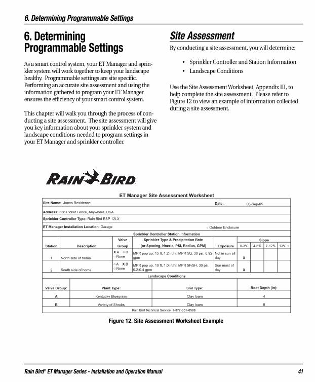
6. Determining Programmable Settings
Rain Bird® ET Manager Series - Installation and Operation Manual 41
6. Determining Programmable SettingsAs a smart control system, your ET Manager and sprin-kler system will work together to keep your landscapehealthy. Programmable settings are site specific.Performing an accurate site assessment and using theinformation gathered to program your ET Managerensures the efficiency of your smart control system.
This chapter will walk you through the process of con-ducting a site assessment. The site assessment will giveyou key information about your sprinkler system andlandscape conditions needed to program settings inyour ET Manager and sprinkler controller.
Site AssessmentBy conducting a site assessment, you will determine:
• Sprinkler Controller and Station Information
• Landscape Conditions
Use the Site Assessment Worksheet, Appendix III, tohelp complete the site assessment. Please refer toFigure 12 to view an example of information collectedduring a site assessment.
Rain Bird Technical Service: 1-877-351-6588
Figure 12. Site Assessment Worksheet Example

6. Determining Programmable Settings
Rain Bird® ET Manager Series - Installation and Operation Manual 42
Sprinkler Controller and Station InformationThe sprinkler system delivers water to the landscaperefilling the soil reservoir. To use an ET Manager, the sitemust have an operating sprinkling system completewith automatic valves controlled by a sprinkler con-troller. The sprinkler system capabilities affect how toprogram your sprinkler controller and your ET Manager.Refer to chapter 4, Programming, for more detail onprogramming your sprinkler controller.
Sprinkler Controller TypeAn ET Manager is compatible with almost all sprinklercontrollers including basic non-ET controllers andadvanced ET-based controller systems. The sprinklercontroller type must be determined upon installation todecide the Output Method used with your ET Manager.
Non-ET based sprinkler controllers are installed andprogrammed to the Enable Output Method (see“Output Method” below). ET-based sprinkler con-trollers are installed and programmed to an advancedOutput Method. Refer to chapter 8, Advanced OutputMethods, to determine which method is appropriatefor your ET-based sprinkler controller.
StationStations on a sprinkler controller are connected to spe-cific valves that are activated according to your ETManager. Each station should have plants with similarwater requirements within its area. Stations are alsoreferred to as “zones.” Stations must be assigned tospecific ET Manager Valve Groups A, B, or none.
Note: When a station has a wide variety of waterrequirements within its area, it becomes necessary towater according to the area in the station that needs themost water to keep plants healthy.
DescriptionThe station description can include information thatdescribes the on-site location of the station and thecondition of the landscape in the station at the time ofthe site assessment.
Valve Group AssignmentYour ET Manager supports two valve groups. Forexample, Valve Group A may be assigned to lawn sta-tions and Valve Group B may be assigned to shrub sta-tions. Determine how the Valve Groups are to beassigned to each station.
To use both Valve Groups A and B with your sprinklingsystem, the common wire to A valves must be separatefrom the common wire to B valves. While the sprinklersystem is being installed two common wires must beused; one to Valve Group A and one to Valve Group B.When retrofitting an existing system, a spare wire canbe used for the common on one of the valve groups.
Sprinkler Type and Precipitation RateSprinkler systems are a complex arrangement of sprin-kler heads, valves, and piping. Sprinkler type, layout,nozzle size, and water pressure affect the rate water isapplied by the sprinklers. The rate at which water isapplied to the landscape or the precipitation rate ismeasured in inches per hour.
The precipitation rate is needed to determine the sta-tion run times, or how long the valves should run todeliver the programmed ET Manager IrrigationAmounts. For example, if the Irrigation Amount is 0.5inches and the station sprinklers apply 1.50 inches ofwater per hour, it would take 20 minutes to apply theIrrigation Amount (0.50 inches). Refer to Appendix Vfor more information on calculating precipitation ratesand station run times.
Sprinkler systems apply water with varying degrees ofuniformity or efficiency. Station run times may need tobe increased to compensate weaknesses in sprinklercoverage.
ExposureWhen assessing a site it is important to observe condi-tions, such as environmental exposures. Sun exposureand high wind exposure increase the rate of evapora-tion. By understanding the exposures, you can makebetter water scheduling decisions. Exposure areas thatwould increase the rate of evaporation may need longer

6. Determining Programmable Settings
Rain Bird® ET Manager Series - Installation and Operation Manual 43
station run times, while exposure areas that woulddecrease the rate of evaporation may be fine withshorter station run times.
SlopeWhen sprinklers apply water faster than the soil canabsorb, water can run-off. Sloping landscapes increas-es the chance of run-off occurring. Frequent wateringcycles programmed in the sprinkler controller can min-imize this problem. The ET Manager will allow thesprinkler controller to operate multiple watering cyclesto prevent run-off. This method of watering, oftenreferred to as cycle and soak, is preferred because itprevents run off.
Landscape ConditionsLandscape conditions determine how much and howoften your landscape should be watered. Three land-scape factors, plant type, soil type, and root depth, areessential in a site assessment. Using these factors youcan accurately program your ET Manager to your spe-cific landscape needs.
Plant TypePlants need water to transport nutrients for cell devel-opment and temperature control. Different plant typesrespond to changing environmental conditions in dif-ferent ways. For example, cool season grasses respondto high evaporation rates by going into dormancy dur-ing the hottest days of the year. Other plants likeshrubs tend to have deeper roots and can sustain high-er evaporation than grass by accessing water deeper inthe soil.
It is important to understand what plant types areincluded in the landscape. As stated previously ValveGroup A is typically assigned to lawn stations and ValveGroup B is typically assigned to shrub stations. Thesedifferent plant types use water at different rates requir-ing different Irrigation Amounts and LandscapeAdjustment Percentages.
Soil TypeSoil is a habitat for soil organisms and plant roots. Itfunctions as a storehouse for nutrients and a waterreservoir. It contains and supplies water, oxygen, nutri-ents, and provides mechanical support for plantgrowth.
Soil type and root depth largely determine the amountof water that can be stored in the soil. There are severalways to determine soil type, i.e. sand, loam, clay, etc. Alaboratory soil test can provide exact information. Soiltype can be determined by a simple feel test; seeAppendix IV for the diagram.
Root DepthPlant roots draw water from the soil. Deeper rootsincrease the availability of water for the plants becauseplants with deep roots can access water at greater soildepths, see Figure 13. Use a shovel or soil probe todetermine your plant root depth.
Note: During plant establishment, the plant root depthincreases. Because roots will grow deeper during estab-lishment, the Irrigation Amount will need to beincreased accordingly. The result will be to water lessfrequently, as the plant roots grow deeper.
Figure 13. Deep Roots vs. Shallow Roots
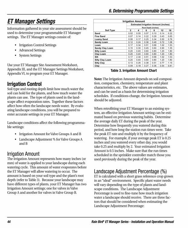
6. Determining Programmable Settings
Rain Bird® ET Manager Series - Installation and Operation Manual 44
ET Manager SettingsInformation gathered in your site assessment should beused to determine your programmable ET Managersettings. The ET Manager settings consist of:
• Irrigation Control Settings
• Advanced Settings
• System Settings
Use your ET Manager Site Assessment Worksheet,Appendix III, and the ET Manager Settings Worksheet,Appendix VI, to program your ET Manager.
Irrigation ControlSoil type and rooting depth limit how much water thesoil can hold for the plants, and how much water theplants can use. The type of plants used in the land-scape affect evaporation rates. Together these factorsaffect how often the landscape needs water. By evalu-ating landscape conditions, you will be prepared toenter accurate settings in your ET Manager.
Landscape conditions affect the following programma-ble settings:
• Irrigation Amount for Valve Groups A and B
• Landscape Adjustment % for Valve Groups Aand B
Irrigation Amount The Irrigation Amount represents how many inches (ormm) of water is applied to your landscape during eachwatering cycle. This amount of water evaporates beforethe ET Manager will allow watering to occur. Theamount is based on your soil type and the plant’s rootdepth (refer to Table 3). Because your landscape mayhave different types of plants, your ET Manager has twoIrrigation Amount settings; one for valves in ValveGroup A and another for valves in Valve Group B.
Note: The Irrigation Amount depends on soil composi-tion, compaction, chemistry, temperature and plantcharacteristics, etc. The above values are estimates,and can be used as a basis for determining irrigationschedules. If conditions change, the Irrigation Amountshould be adjusted.
When retrofitting your ET Manager to an existing sys-tem, an effective Irrigation Amount setting can be esti-mated based on previous watering habits. Determinethe average daily ET during the peak of the year.Determine how frequently you watered during thisperiod, and how long the station run times were. Takethe peak ET rate and multiply it by the frequency ofwatering. For example, if your average peak ET is 0.25inches and you watered every other day, you wouldtake 0.25 and multiply by 2. Your estimated IrrigationAmount is 0.5 inches. Make sure that the run timesscheduled in the sprinkler controller match those youused previously during the peak of the year.
Landscape Adjustment Percentage (%)ET is calculated with a short grass reference crop grownin an “ideal” environment. Specific plant water needswill vary depending on the type of plants and land-scape conditions. The Landscape AdjustmentPercentage is used to fine-tune how much irrigationwater a landscape should receive. There are three fac-tors that should be considered when estimating theLandscape Adjustment Percentage:
I r r i g a ti o n A m o u n t E s t i m a t e d I r r i g a t i o n A m o u n t ( i n c h e s )
R o o t D e p t h ( i n c h e s )
S o i l T y p e 2 4 6 8 1 2 1 8 S a n d 0 . 0 2 0 . 0 5 0 . 0 7 0 . 1 0 0 . 1 4 0 . 2 2
F i n e S a n d 0 . 0 7 0 . 1 4 0 . 2 2 0 . 2 9 0 . 4 3 0 . 6 5
L o a m y S a n d 0 . 0 8 0 . 1 7 0 . 2 5 0 . 3 4 0 . 5 0 0 . 7 6
S a n d y L o a m 0 . 1 2 0 . 2 4 0 . 3 6 0 . 4 8 0 . 7 2 1 . 0 8
L o a m 0 . 1 7 0 . 3 4 0 . 5 1 0 . 6 8 1 . 0 2 1 . 5 3
S a n d y C l a y L o a m 0 . 1 5 0 . 3 0 0 . 4 5 0 . 6 0 0 . 9 0 1 . 3 5
S i l t y L o a m 0 . 2 0 0 . 4 0 0 . 6 0 0 . 8 0 1 . 2 0 1 . 8 0
C l a y L o a m 0 . 2 0 0 . 4 0 0 . 6 0 0 . 8 0 1 . 2 0 1 . 8 0
S i l t 0 . 1 7 2 . 3 4 0 . 5 1 0 . 6 8 1 . 0 2 1 . 5 3
S i l t y C l a y L o a m 0 . 2 0 0 . 4 0 0 . 6 0 0 . 8 0 1 . 2 0 1 . 8 0
S i l t y C l a y 0 . 1 3 0 . 2 6 0 . 3 8 0 . 5 1 0 . 7 7 1 . 1 5
C l a y 0 . 0 9 0 . 1 8 0 . 2 7 0 . 3 6 0 . 5 4 0 . 8 1
Table 3. Irrigation Amount Chart

6. Determining Programmable Settings
Rain Bird® ET Manager Series - Installation and Operation Manual 45
• Plant Species
• Planting Density
• Microclimate
As general rule the Landscape Adjustment Percentagesshould range between 70% to 100% for turf grass and50% to 80% for shrubs.
Note: Additional station-by-station adjustments canalso be made in the sprinkler controller. Once your ETManager is installed, the system should be monitoredand these settings may need to be changed.
Note: The Weather Reach Signal Provider (WRSP) caninclude in the weather signal a crop coefficient (Kc)value. This is done as a service to the end user becausethe Kc value can change over the course of the season.Check with the WRSP to see if regional Kc value is beingused. If it is being used, the Landscape AdjustmentPercentage should be set based on recognizing thisregional service.
Example: If a WRSP is sending a seasonal Kc value, it istypically based on the predominate turf grass in thearea. In this case, Landscape Adjustment Percentagewould normally be left at 100% for turf schedules. TheLandscape Adjustment Percentage for shrub schedulesshould be adjusted based on the Kc value already beingapplied to ET. For example, if the broadcast Kc valuewas 80% at mid season and a shrub LandscapeAdjustment Percentage of 50% was needed then theLandscape Adjustment Percentage should be set at 62% (50% / 80% = 62%).
Water WindowThe ET Manager Water Window needs to be synchro-nized with the start and run times programmed in yoursprinkler controller. There are two Water Windows usedto manage the system:
• Automatic Window: The period of time thatthe ET Manager controls watering cycles basedon ET.
• Daily Window: An optional period whenwatering can occur as programmed in the
sprinkler controller, and not controlled by theET Manager.
Automatic WindowThe Automatic Window is a period of time based on thefirst start time programmed in the sprinkler controllerand the amount of time it takes to complete all water-ing cycles controlled by ET. When Valve Groups A or Bare enabled, watering is allowed during the AutomaticWindow.
At the opening of the Automatic Window, the ETManager determines if watering should occur. If water-ing is needed the Valve Group Indicator Light for A or Bwill be green and watering is enabled, allowing thesprinkler controller to activate valves. It remainsenabled through the duration of the AutomaticWindow. If the Moisture Level for the valve group hasnot reached zero, the Valve Group A or B Indicator Lightremains red and watering is suspended through theAutomatic Window period.
When watering is enabled in a valve group and thesprinkler controller activates the valves, the ETManager uses a built-in electrical sensor to verify thatwatering occurred. If watering is not detected duringthe Automatic Window, watering remains enabledthrough the next day’s Automatic Window.
Daily WindowIf there are stations that require non-ET based manage-ment they can be programmed in the sprinkler con-troller to water as needed using the Daily Window.These stations must be programmed in the sprinklercontroller to water during a period outside theAutomatic Window period. Stations programmed inthe sprinkler controller can be set to water any day, butthe watering time must occur within the Daily Windowperiod.
The Daily Window will allow watering every day sched-uled in the sprinkler controller. When the DailyWindow opens, both the Valve Group A and ValveGroup B Indicator Lights will turn green. Watering isenabled during this period.

6. Determining Programmable Settings
Rain Bird® ET Manager Series - Installation and Operation Manual 46
Available DaysThe days available for watering can be programmed inyour ET Manager or in your sprinkler controller.Typically Available Watering Days are set to “all” oreveryday. Examples of limiting available days includescheduled maintenance, facility use, or local wateringrestrictions. Depending on your watering situation,your ET Manager can be programmed to water on:
• All days• Even days• Odd days• Odd days with the 31 of the month off • Custom days
Advanced Settings
Effective Rain Settings Not all rainfall is effective rain. Rain that falls too quicklywill run off before reaching the root zone, and rain thatfalls when the soil is completely saturated will run off aswell. Soil infiltration is the rate at which water enters thesoil. Different soil types have different intake rates. TheEffective Rain Settings in the ET Manager are based onsoil intake rate and soil moisture saturation limits.
Maximum Hourly Rain: The Maximum Hourly Rainis the maximum amount of rain that should be accept-ed each hour in the soil moisture level. See Table 4 toestimate the Maximum Hourly Rain according to yoursoil type.
Saturation Allowance: The Saturation Allowance isthe amount of rain it takes to saturate the soil after sat-isfying the Irrigation Amount and before runoff occurs.Saturation Allowance settings are typically half theIrrigation Amount.
Normal watering cycles bring the soil moisture level tofield capacity. Heavy rainfall will bring the soil moisturecontent beyond field capacity to a saturated level (seeFigure 14). Additional rainfall beyond this limit canpercolate below the root-zone or run-off, and may notbe available to the plant. The Saturation Allowance set-ting represents the difference between field capacityand saturation. The ET Manager uses this amount tolimit the total amount of rain that can accumulate inthe Moisture Level. Saturation Allowance + Irrigation Amount – CurrentMoisture Level = Total Allowed Rain
For example, if it rains 1.00”, only 0.65 “of rain will becounted as effective. If the Saturation Allowance is 0.25“ plus an Irrigation Amount of 0.5” minus a CurrentMoisture Level of 0.10” = 0.65” of Total Allowed Rain.
Note: A general guideline is to set the SaturationAllowance to half the Irrigation Amount.
Soil Type Max HourlyRain
(inches)Clay 0.10
Silty Clay 0.15Clay Loam 0.20
Loam 0.35Sandy Loam 0.40Loamy Sand 0.50
Sand 0.60Information from Soil Conservation Service NationEngineering Handbook, September 1997.
Table 4. Guide to Determine Maximum Hourly Rain
Readily availab le
water
Saturation
Saturation Allowance
Field Capacity
Gravitational Water (rapid drainage)
Irrigation Amount (Typically 50% of AW)
Available Water (AW)
Permanent Wilting Point
Hygroscopic Water (essentially no
drainage)
Figure 14. Soil Moisture Holding Capacities

6. Determining Programmable Settings
Rain Bird® ET Manager Series - Installation and Operation Manual 47
Historical ETThe ET Manager can be set to operate using historicalET data, instead of the weather signal data. If a prob-lem occurs and the ET Manager is not receiving theweather signal, it will continue to operate using histori-cal ET data as a default ET. This setting represents anaverage daily ET for each month.
Note: A Historical ET database is available in your RainBird ET Manager Scheduler program found on the pro-vided CD.
System SettingsYour ET Manager System Settings establishes thesource of the weather signal information, how your ETManager interacts with your sprinkler controller, andother valuable tools. The System Settings details arediscussed in chapter 3, Programming.
Your ET Manager System Settings include:
• Data Source: The Data Source settings consistof specific settings programmed to access theappropriate weather signal.
• Options: Option settings allow you to programthe units used (English or Metric) and a securi-ty password.
• Output Method: The ET Manager can utilizefour Output Methods. In most cases, the“Enable” Output Method is the standardmethod.
When conducting the site assessment, your ETManager System Settings may have been previouslyprogrammed. By documenting these settings, you willbe able to verify the settings have been programmedcorrectly.
ET Manager SchedulerThe Rain Bird ET Manager Scheduler software program,included with your ET Manager, was developed to gen-erate accurate watering schedules. The ET ManagerScheduler uses site-specific information to help youprepare a watering schedule that can be programmedin your sprinkler controller. The ET Manager Scheduleralso determines the initial settings for your ETManager. We encourage using this program for makingET Manager and sprinkler controller programmingdecisions. The ET Manager Scheduler Operation Guideis available from the CD included with your ETManager.
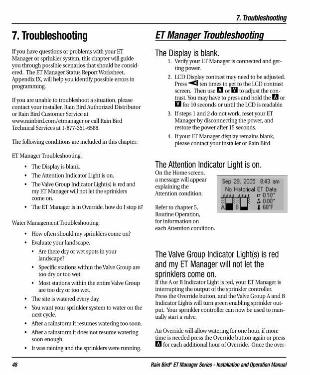
7. Troubleshooting
Rain Bird® ET Manager Series - Installation and Operation Manual 48
7. TroubleshootingIf you have questions or problems with your ETManager or sprinkler system, this chapter will guideyou through possible scenarios that should be consid-ered. The ET Manager Status Report Worksheet,Appendix IX, will help you identify possible errors inprogramming.
If you are unable to troubleshoot a situation, pleasecontact your installer, Rain Bird Authorized Distributoror Rain Bird Customer Service atwww.rainbird.com/etmanager or call Rain BirdTechnical Services at 1-877-351-6588.
The following conditions are included in this chapter:
ET Manager Troubleshooting:
• The Display is blank.
• The Attention Indicator Light is on.
• The Valve Group Indicator Light(s) is red andmy ET Manager will not let the sprinklers come on.
• The ET Manager is in Override, how do I stop it?
Water Management Troubleshooting:
• How often should my sprinklers come on?
• Evaluate your landscape.
• Are there dry or wet spots in your landscape?
• Specific stations within the Valve Group are too dry or too wet.
• Most stations within the entire Valve Group are too dry or too wet.
• The site is watered every day.
• You want your sprinkler system to water on thenext cycle.
• After a rainstorm it resumes watering too soon.
• After a rainstorm it does not resume wateringsoon enough.
• It was raining and the sprinklers were running.
ET Manager Troubleshooting
The Display is blank.1. Verify your ET Manager is connected and get-
ting power.
2. LCD Display contrast may need to be adjusted.Press à ten times to get to the LCD contrastscreen. Then use Œ or Õ to adjust the con-trast. You may have to press and hold the Œ orÕ for 10 seconds or until the LCD is readable.
3. If steps 1 and 2 do not work, reset your ETManager by disconnecting the power, andrestore the power after 15 seconds.
4. If your ET Manager display remains blank,please contact your installer or Rain Bird.
The Attention Indicator Light is on.On the Home screen,a message will appearexplaining theAttention condition.
Refer to chapter 5,Routine Operation,for information oneach Attention condition.
The Valve Group Indicator Light(s) is redand my ET Manager will not let the sprinklers come on.If the A or B Indicator Light is red, your ET Manager isinterrupting the output of the sprinkler controller.Press the Override button, and the Valve Group A and BIndicator Lights will turn green enabling sprinkler out-put. Your sprinkler controller can now be used to man-ually start a valve.
An Override will allow watering for one hour, if moretime is needed press the Override button again or pressΠfor each additional hour of Override. Once the over-

7. Troubleshooting
Rain Bird® ET Manager Series - Installation and Operation Manual 49
ride time has elapsed watering will be interrupted asbefore. Press Õ to 0 hours to end manual override inthe ET Manager.
The ET Manager is in Override, how do Istop it?Press Õ to 0 hours to end manual override in the ETManager.
Water Management Troubleshooting
How often should my sprinklers come on?Your ET Manager uses real-time weather information todetermine when watering is needed. Your sprinkler sys-tem may water more frequently in the summer months,and less frequently in the spring and fall months sincewatering is now based on weather (which affects howmuch water evaporates from your soil). Your ETManager automatically adjusts throughout the year tokeep the Moisture Levels in your soil reservoir at anoptimum level for the health of your plants.
Evaluate your landscape.Before making any adjustments to the settings of eitheryour ET Manager or your automatic sprinkler con-troller, make sure that the entire sprinkler system is ingood working order. It is important to be certain thatthere are no broken sprinkler heads or broken pipesaffecting the performance of your system. Landscapesand automated sprinkler systems are subject to imper-fections that can be corrected. You may need to con-tact your landscape installer or sprinkler profes-sional.
1. Perform a walk through evaluation inspectingyour sprinkler system while each zone is run-ning.
2. If problems in the sprinkler system are detect-ed, please fix the problems or call sprinklerprofessionals to assist you.
Are there dry or wet spots in your landscape?Dry and wet spots are often caused by problems withyour sprinkler system or the program in your sprinklercontroller. Spots within a station are areas where theplant life is not uniform with the rest of the landscapein the station, and these “spots” are either too dry ortoo wet.
1. Check the sprinkler heads near the spot that isdry or wet. It is possible that a broken head ornozzle, or a clogged nozzle needs to bereplaced.
2. Check the layout of your sprinkler design.Proper sprinkler designs should ensure head tohead coverage. Changing a nozzle size, addingor moving a head may improve distributioncoverage.
3. If steps 1 and 2 do not solve the problem,check the run times on your sprinkler con-troller. Adding additional run time for the sta-tion where the spot appears may compensatefor minor sprinkler system inefficiencies.
Note: Adjust the run time using small intervals of time.Monitor the spots after an adjustment has been made.This will help determine what run time is optimal toprevent dry or wet spots.
Specific stations within the Valve Groupare too dry or too wet.Stations are the distinct areas in your landscapewatered by one valve in Valve Group A or B. Dry or wetstations are often caused by a run time problem pro-grammed in your sprinkler controller.
1. Check the run time on your sprinkler controllerfor this station. The dry or wet station can becaused by too little or too much watering timefor that station.
2. Manually water the station if it is too dry to getit the water it needs.
7. Troubleshooting
Rain Bird® ET Manager Series - Installation and Operation Manual 50
Note: Adjust the run time using small intervals of time.This will help determine what run time is optimal toprevent dry or wet zones.
Most stations within the entire ValveGroup are too dry or too wet.There are two possible causes of all the stations withinentire Valve Group being to dry or too wet:
• The Irrigation Amounts for A or B were not cor-rectly programmed.
• A run time problem programmed in yoursprinkler controller.
If your Valve Group is overly dry, water the stations inthe Valve Group by following the steps outlined in “Youwant your sprinkler system to water on the nextcycle” pg. .
Please follow these steps:
1. Check the run times on your sprinkler con-troller. The dry or wet Valve Group can becaused by too little or too much run time foreach station in the Valve Group.
2. Adjust the run time using small intervals oftime. This will help determine what run time isoptimal to prevent dry or wet stations.
3. If steps 1 and 2 do not fix this problem, youshould adjust the Irrigation Amounts in the ETManager.
4. Increase or decrease your Irrigation Amountsfor Valve Group A or B.
Main Menu �Settings �Irrigation Control�Irrigation Amount & Adjust
Increasing the Irrigation Amount decreases thefrequency of watering and decreasing theIrrigation Amount increases the frequency ofwatering. You want to increase your IrrigationAmount if you are experiencing a wet Valve Groupand you want to decrease your Irrigation Amountif you have a dry Valve Group.
Refer to chapter 6, Determining ProgrammableSettings, for more information to properly adjust theIrrigation Amount values.
The site is watering every day.
There are three possible causes of why the site is water-ing everyday:
• The Irrigation Amounts for A or B are pro-
grammed too low.
• The Automatic Window is not correctly pro-grammed.
• The ET Manager was not properly installed.
1. The Irrigation Amounts for Valve Group A or Bcould be too low. Refer to chapter 6,Determining Programmable Settings, for moreinformation to properly adjust the IrrigationAmount values.
Main Menu �Settings �Irrigation Control�Irrigation Amount & Adjust
2. The Automatic Window setting may not be syn-chronized to the time of day when watering isscheduled to occur in the sprinkler controller. Ifthe watering cycle occurs outside the pro-grammed Automatic Window, watering is notdetected and the Current Moisture Level(s) isnot adjusted. Refer to chapter 3, Programming,for more information on programming theAutomatic Window.
Main Menu �Settings �Irrigation Control�Water Window �Automatic Window
3. Wiring is not properly installed. Follow theValve Control Test steps outlined in chapter 4,System Check. If test fails, wiring is not proper-ly installed.
51

7. Troubleshooting
Rain Bird® ET Manager Series - Installation and Operation Manual 51
You want your sprinkler system to wateron the next cycle.There may be occasions when, in your judgment, thesprinklers should water tonight or the next wateringcycle. When the Valve Group A or B Indicator Light isgreen, then watering will be allowed during the nextscheduled cycle. If the Valve Group A or B IndicatorLight is red and you want to allow the next scheduledcycle to come on, then adjust the Current MoistureLevel for Valve Group A and/or B to allow watering.
1. Determine which Valve Group A or B you wantto run. Remember the A and B Moisture Levelsare specific to types of plants (e.g. lawn andshrubs).
2. Decrease the A or B Moisture Level to zero.
Main Menu �Irrigation Status
�“A” or “B” Moisture Level
3. Once the level reaches zero the red Valve GroupIndicator Light will change to green and yourET Manager will allow your sprinkler system towater a complete cycle once the AutomaticWindow is open.
Note: The Valve Group Indicator Light(s) will not turngreen if the Automatic Window is open, or if the currentday is a no water day. If either of these conditions isoccurring, the Home screen will notify you.
After a rainstorm my sprinkler systemresumes watering too soon.Walk through each step below to prevent your sprinklersystem from watering too soon after a rainstorm.
1. The location of your optional rain gauge maybe poorly sited. Make certain there are noobstacles blocking rain from entering the raingauge.
2. Check the Rain Source to verify the ETManager is programmed to the correct source,specifically when using an optional rain gauge.
Main Menu �Settings �System �Data Source �Rain Source
3. The Maximum Hourly Rain setting may be lim-iting the amount of rainfall applied to theMoisture Levels. Change the Maximum HourlyRain to a higher amount to allow the ETManager to accept more rainfall in theMoisture Levels for Valve Group A and B.
Main Menu �Settings �Irrigation Control�Advanced Settings �Effective Rain Settings�Max Hourly Rain
4. The Saturation Allowance for A or B may be toolow. Change the Saturation Allowance to ahigher amount to allow the ET Manager toaccept more rainfall in the Moisture Levels forValve Group A and B.
Main Menu �Settings �Irrigation Control�Advanced Settings �Effective Rain Settings�Saturation Allowance A or B
5. The weather signal rainfall value may not cor-rectly represent rainfall at your site. Connectan optional rain gauge, see chapter 2,Installation.
After a rainstorm my sprinkler systemdoes not resume watering soon enough.If your sprinkler system does not resume watering soonenough after a rainstorm, follow these steps:
1. Check the Rain Source to verify the ETManager is programmed to the correct source,specifically when using an optional rain gauge.
Main Menu �Settings �System �Data Source �Rain Source

7. Troubleshooting
Rain Bird® ET Manager Series - Installation and Operation Manual 52
2. Lower the Max Hourly Rain setting for ValveGroup A or B. The Maximum Hourly Rain set-ting may be limiting the amount of rainfallapplied to the Moisture Levels. Change theMaximum Hourly Rain to a lower amount toallow the ET Manager to limit rainfall in theMoisture Levels for Valve Group A or B.
Main Menu �Settings �Irrigation Control�Advanced Settings �Effective Rain Settings�Max Hourly Rain
3. The Saturation Allowance for A or B may be toohigh. Lower the Saturation Allowance settingsfor Valve Groups A or B. The SaturationAllowances for A and B create a limit to theamount of rain that can accumulate in theMoisture Levels. The ET Manager uses thisamount to limit the total amount of rain thatcan accumulate in the Moisture Level.
Main Menu �Settings �Irrigation Control�Advanced Settings �Effective Rain Settings�Saturation Allowance A or B
4. The weather signal rainfall value may not cor-rectly represent rainfall at your site. Connectan optional rain gauge, see chapter 2,Installation.
It was raining and the sprinklers were running.
1. Check the Weather Info for the last hour of rainto verify rain data is being reported by your ETManager.
Main Menu �Weather Info �Rain
2. Check the Rain Source to verify the ETManager is programmed to the correct sourceto ensure the rain data is correct.
Main Menu �Settings �System �Data Source �Rain Source
3. Program a 1 Hour Rain Interrupt to interruptwatering until rain accumulations reach belowthe programmed Rain1 Hour setting. Seechapter 3, Programming, for more information.
Main Menu �Settings �Weather Interrupt�Rain 1 Hour Rain
4. Program a 24 Hour Rain Interrupt to interruptwatering until rain accumulations reach belowthe programmed Rain 24 Hour setting. Seechapter 3, Programming, for more information.
Main Menu �Settings �Weather Interrupt�Rain 24 Hour Rain
Note: Remember that small amounts of rainfallmay not be enough to warrant a 1 Hour or 24Hour Rain Interrupt.
Note: If the Moisture Level for Valve Group A or Bis equal to zero at the opening of the AutomaticWindow, sprinkling will remain enabled through-out the Automatic Window unless 1 Hour or 24Hour Rain Interrupts are programmed. Rain thatfalls during normal watering cycle will be account-ed for in the Moisture Levels for Valve Group A andB.
Rain Bird Note: New models of the Rain Bird ESPcontroller family offer a “RASTER” test, which isused to diagnose electrical problems with thesprinkler system. Before executing the RASTERtest press the Override button on the ET Mangerto enable the controller common.

8. Advanced Output Methods
Rain Bird® ET Manager Series - Installation and Operation Manual 53
8. Advanced Output MethodsThe ET Manager is an accessory to a sprinkler con-troller to provide real-time ET based water manage-ment for the sprinkler system. The interface betweenyour sprinkler controller and the ET Manager utilizesone of four different Output Methods. The capabilitiesof the sprinkler controller and site-specific needs deter-mine which Output Mode should be used. To deter-mine which Output Method is used with your sprinklercontroller, please review this chapter.
Output Methods• Enable: This is the most common setting. A
sprinkler controller output is enabled to allowwatering only when needed.
• Enable A then B: This output operates thesame as the “Enable” method with one signifi-cant difference. There may be instances whenwatering needs to be spread over two days.The A then B mode allows watering on onlyone valve group per day, then alternates to theother valve group on the next available day.
• ET and Rain Pulse: ET-based controllers canrecognize these inputs. A dry contact switchclosure signal represents 0.01” of ET. The rainoutput signals 0.01” of rain.
• ET Pulse with Weather Interrupt: ET Pulsewith Weather Interrupt is similar to ET andRain Pulse with a second output acting as asensor interrupt to prevent watering if any oneof the three Weather Interrupt conditionsoccurs; rain, freezing conditions or high wind.A dry contact switch closure signal represents0.01” of ET.
This chapter focuses on all Output Methods exceptEnable.
Enable A then BSome sites need to spread watering over 2 days, water-ing a portion the site one night and the remaining sitethe next night. The “Enable A then B” Output Methodseparates watering of Valve Group A and B over a twoday period. The Enable A then B Output Method oper-ates the same as the Enable mode described in thismanual with the difference that the valve groups willnever water during the same Automatic Window; ValveGroup A waters one night “then” B the next night. Inorder to implement the Enable A then B OutputMethod:
• Your sprinkler controller, ET Manager, andvalves must be installed correctly, see Figure 15.
• Your ET Manager must be correctly pro-grammed.
• Your sprinkler controller must be programmedcorrectly.

8. Advanced Output Methods
Rain Bird® ET Manager Series - Installation and Operation Manual 54
Mounting and installation is the same as the EnableOutput Method. The difference is the Valve Groupwiring. Divide the valves into 2 valve common wiregroups, one for Valve Group A and the other for ValveGroup B. Valves to be watered in one 24-hour periodmust be on a separate “common wire” from thosewatered in the next 24-hour period, where valves inValve Group A must be connected to the A wire termi-nal and valves in Valve Group B must be connected tothe B wire terminal on your ET Manager.
ET Manager Programming for “A Then B”All programming of your ET Manager is the same asdescribed in the manual for the Enable mode with thefollowing exceptions:
1. The Output Method must be set to Enable Athen B.
Main Menu �Settings �System �Output Method �Enable A then B
2. The Irrigation Amount and LandscapeAdjustment settings can be different to accom-modate specific site needs. In this instance,the resulting frequency may be different caus-ing the sequence to change. For example, if
Figure 15. ET Manager Terminal Connections ET Enable A Then B
Wiring “A Then B”

8. Advanced Output Methods
Rain Bird® ET Manager Series - Installation and Operation Manual 55
Valve Group A watered one night and the nextnight Valve Group B does not need to water butValve Group A needs to be watered, then Awould water again, hence changing thesequence. This is not a problem, but be awarethat the sequence could change.
3. Automatic Window settings need to encompassthe water window for both programs in thecontroller. For example, if program A is set tostart at 10:00 PM and finish at 4:00 AM andprogram B is set to start at 11:00 PM and finishat 6:00 AM, the Automatic Window should beset to start at 10:00 PM and run for 8 and a halfhours to close at 6:30 AM.
Programming the Sprinkler Controller for“A Then B”There are several essential steps to follow when pro-gramming the sprinkler controller for the ET Managerto water Valve Group A one day “then” Valve Group Bthe next day.
1. Valves wired to each Valve Group (A and B)must be assigned to separate programs in thesprinkler controller. For example, valves inValve Group A should be assigned to ProgramA in the sprinkler controller.
2. Each sprinkler controller program should beset to the same time.
3. The sprinkler controller MUST support theoption to “overlap” programs. Both programsmust run at the same time. Even though thesprinkler controller will attempt to operateboth programs at the same time, the ETManager will only allow one valve group tooperate at a time.
4. Station run times need to be programmed toapply enough water to satisfy the IrrigationAmounts programmed in your ET Manager.
5. Note the earliest start time for both programsand the ending time for the last program. Thiswill be needed to program the AutomaticWindow in your ET Manager.
ET & Rain PulseThere are compatible advanced ET-based sprinklercontrollers that can use the ET Manager as an ETsource. Some ET-based controllers accept a pulse inputas an ET source; a momentary switch closure for each0.01” of ET. They often have a similar input for rain.The sprinkler controller uses these values to automati-cally adjust watering schedules.
The ET Manager has an ET and Rain pulse output thatprovides a dry contact switch closure representing 0.01”of ET and 0.01” of rain. The rain data comes from theselected rain source. To utilize the ET and Rain PulseOutput Method:
• Your sprinkler controller, ET Manager, andvalves must be installed correctly, see Figure 16.
• Your ET Manager must be correctly programmed.
• Your sprinkler controller must be programmedto recognize pulse inputs.
Note: When using this Output Method, all schedulingdecisions including days of operation are made by thesprinkler controller. The ET Manager simply inputs theET and rain data to the sprinkler controller.
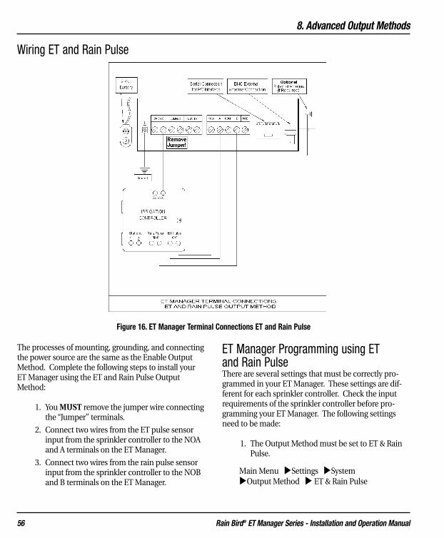
8. Advanced Output Methods
Rain Bird® ET Manager Series - Installation and Operation Manual 56
The processes of mounting, grounding, and connectingthe power source are the same as the Enable OutputMethod. Complete the following steps to install yourET Manager using the ET and Rain Pulse OutputMethod:
1. You MUST remove the jumper wire connectingthe “Jumper” terminals.
2. Connect two wires from the ET pulse sensorinput from the sprinkler controller to the NOAand A terminals on the ET Manager.
3. Connect two wires from the rain pulse sensorinput from the sprinkler controller to the NOBand B terminals on the ET Manager.
ET Manager Programming using ET and Rain PulseThere are several settings that must be correctly pro-grammed in your ET Manager. These settings are dif-ferent for each sprinkler controller. Check the inputrequirements of the sprinkler controller before pro-gramming your ET Manager. The following settingsneed to be made:
1. The Output Method must be set to ET & RainPulse.
Main Menu �Settings �System �Output Method � ET & Rain Pulse
Wiring ET and Rain Pulse
Figure 16. ET Manager Terminal Connections ET and Rain Pulse
8. Advanced Output Methods
Rain Bird® ET Manager Series - Installation and Operation Manual 57
2. There are three settings in the Pulse menu:
Main Menu �Settings �System �Pulse
a. Per Minute: There are two options either 1or 10 pulses per minute. This setting controlsthe pulse rate so the host sprinkler controllercan recognize each pulse.
b. ET Duration: For each 0.01” of ET a dry con-tact switch closure is made. The number of sec-onds the switch remains closed for each pulse isprogrammed here.
c. Rain Duration: For each 0.01” of rain a drycontact switch closure is made. The number of seconds the switch remains closed for eachpulse is programmed here.
3. Standard Enable settings that are the same:
a. Irrigation Control
i. Advanced Settings
1. Signal Crop Coefficient
2. Wind Adjust Percentage
3. Historical ET
b. System
i. Data Source
1. Weather Region
2. Rain Source
3. Elevation
4. Signal Provider Code
ii. Options
1. Units
2. Password
Sprinkler Controller Programming using ET and Rain PulseEvery ET-based controller implements ET and Raininputs differently. Wiring, settings, programming, andoperations should be described in the users guide foryour sprinkler controller.
Note: Application notes detailing installation and set-tings for specific compatible controllers are available atwww.rainbird.com/etmanager.
ET Pulse with Weather InterruptThe ET Pulse with Weather Interrupt functions thesame as the ET and Rain Pulse Output Method by uti-lizing Weather Interrupt instead of a Rain Pulse. To uti-lize this Output Method:
• Your sprinkler controller, ET Manager, andvalves must be installed correctly, see Figure 17.
• Your ET Manager must be correctly pro-grammed.
• Your sprinkler controller must be programmedto recognize ET pulse input and WeatherInterrupt control.

8. Advanced Output Methods
Rain Bird® ET Manager Series - Installation and Operation Manual 58
The processes of mounting, grounding, and connectingthe power source are the same as for the Enable OutputMethod. Complete the following steps to connect theET and Weather Interrupt circuit:
1. You MUST remove the jumper wire connectingthe “Jumper” terminals.
2. Connect two wires from the ET pulse sensorinput from the sprinkler controller to the NOAand A terminals on the ET Manager.
3. Route the sprinkler controller valve commonthrough the “Com” and “B” terminals on the ETManager.
ET Manager Programming using ET Pulsewith Weather InterruptThere are several settings in your ET Manager that mustbe set correctly for ET Pulse with Weather Interrupt.The settings are different for each sprinkler controller.Check the input requirements of the controller beforeprogramming your ET Manager. The following settingsneed to be made:
1. The Output Method must be set to ET Pulsewith Interrupt.
Main Menu �Settings �System �Output Method � ET Pulse with Interrupt
Wiring ET Pulse with Weather Interrupt
Figure 17. ET Manager Terminal Connections ET Pulse with Weather Interrupt

8. Advanced Output Methods
Rain Bird® ET Manager Series - Installation and Operation Manual 59
2. There are two settings in the Pulse menu:
Main Menu �Settings �System �Pulse
a. Per Minute: There are two options either 1or 10 pulses per minute. This setting controlsthe pulse rate so the host sprinkler controllercan recognize each pulse.
b. ET Duration: For each 0.01” of ET a dry con-tact switch closure is made. The number of sec-onds the switch remains closed for each pulse isprogrammed here.
3. Standard Enable settings that are the same:
a. Irrigation Control
i. Advanced Settings
1. Signal Crop Coefficient
2. Wind Adjust Percentage
3. Historical ET
b. System
i. Data Source
1. Weather Region
2. Rain Source
3. Elevation
4. Signal Provider Code
ii. Options
1. Units
2. Password
c. Weather Interrupt
i. Temperature
ii. Wind
iii. Rain 24 Hour
iv. Rain 1 Hour
Note: When using the ET Pulse with Weather InterruptOutput Method, the Valve Group B Indicator light willturn green. If a Weather Interrupt condition occurs, theValve Group B Indicator Light will turn red to notify youof the interrupt.
Sprinkler Controller Programming usingET Pulse with Weather InterruptEvery ET-based controller implements ET inputs differ-ently. Wiring, settings, programming, and operationsshould be described in the users guide for your sprin-kler controller. The Weather Interrupt overrides thesprinkler controller output.
Note: Application notes detailing installation and set-tings for specific compatible controllers are available atwww.rainbird.com/etmanager.
Using More than One SprinklerController An ET Manager controls a single sprinkler controller.On large projects with more than one controller thehydraulic capabilities of the sprinkler system may limitthe number of valves that operate at a time. Oftenschedules are set up so one group of clocks waters onenight then the other clock waters the next night. Withthe ET Manager this can be accomplished one of twoways.
• The Available Day feature on the ET Managercan limit watering to specific days. For exampleone ET Manager can be programmed to wateron odd days and the other could be set to watereven days.
• Another approach is to use the “Enable A thenB” Output Method described in this chapter.The Enable A then B Output Method allowsValve Group A to water one night “then” B towater the next night.

9. Appendices
Rain Bird® ET Manager Series - Installation and Operation Manual 60
9. AppendicesThe following supplemental recourses are included:
1. Appendix I. ET Manager Menu Structure
2. Appendix II. General ET Manager Settings
3. Appendix III. ET Manager Site AssessmentWorksheet
4. Appendix IV. Soil Texture by Feel Diagram
5. Appendix V. Calculating Precipitation Ratesand Station Run Times
6. Appendix VI. ET Manager Settings Worksheet
7. Appendix VII. Sprinkler ControllerProgramming Worksheet
8. Appendix VIII. ET Manager System Checklist
9. Appendix IX. ET Manager TroubleshootingWorksheet
10. Appendix X. Master Valve and Pump ControlInstallation with ET Manager
Printable versions of the Worksheet Appendices areavailable to download and print fromwww.rainbird.com/etmanager or the CD included withyour ET Manager.
Appendix I.ET Manager Menu Structure
• Weather Info■ Rain
• Last Hour• Last 24 hours• Last 7 Days• Graph
■ Temperature• Current • High Today• Low Today• Graph
■ Wind• Current • High Today• Low Today• Graph
■ Humidity• Current • High Today• Low Today• Graph
• Irrigation Status■ A Moisture Level
• Irrigation Amount• Current Level• Graph
■ B Moisture Level• Irrigation Amount• Current Level• Graph
■ Rain• Last Hour• Last 24 hours• Last 7 Days• Graph
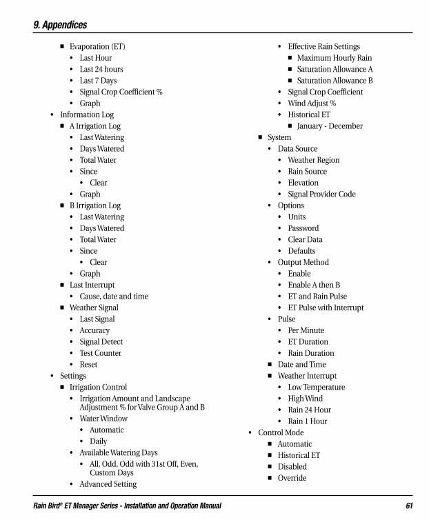
9. Appendices
Rain Bird® ET Manager Series - Installation and Operation Manual 61
■ Evaporation (ET)• Last Hour• Last 24 hours• Last 7 Days• Signal Crop Coefficient %• Graph
• Information Log■ A Irrigation Log
• Last Watering• Days Watered• Total Water• Since
• Clear• Graph
■ B Irrigation Log • Last Watering• Days Watered• Total Water• Since
• Clear• Graph
■ Last Interrupt• Cause, date and time
■ Weather Signal• Last Signal• Accuracy• Signal Detect• Test Counter• Reset
• Settings■ Irrigation Control
• Irrigation Amount and Landscape Adjustment % for Valve Group A and B
• Water Window• Automatic • Daily
• Available Watering Days• All, Odd, Odd with 31st Off, Even,
Custom Days • Advanced Setting
• Effective Rain Settings■ Maximum Hourly Rain■ Saturation Allowance A■ Saturation Allowance B
• Signal Crop Coefficient • Wind Adjust %• Historical ET
■ January - December■ System
• Data Source• Weather Region• Rain Source• Elevation• Signal Provider Code
• Options• Units• Password• Clear Data• Defaults
• Output Method• Enable• Enable A then B• ET and Rain Pulse• ET Pulse with Interrupt
• Pulse• Per Minute• ET Duration• Rain Duration
■ Date and Time■ Weather Interrupt
• Low Temperature• High Wind• Rain 24 Hour• Rain 1 Hour
• Control Mode■ Automatic■ Historical ET■ Disabled■ Override
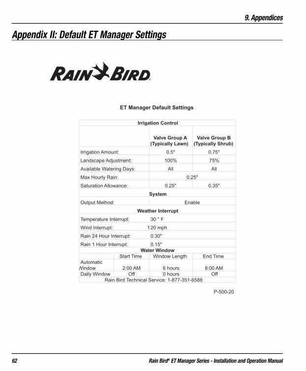
9. Appendices
Rain Bird® ET Manager Series - Installation and Operation Manual 62
Appendix II: Default ET Manager Settings
Irrigation Amount: 0.5" 0.75"
Landscape Adjustment: 100% 75%
Available Watering Days: All All
Max Hourly Rain:
Saturation Allowance: 0.25" 0.35"
Output Method:
Temperature Interrupt:
Wind Interrupt: 1
Rain 24 Hour Interrupt:
Rain 1 Hour Interrupt:
Start Time Window Length End Time
Automatic
Window 2:00 AM 6 hours 8:00 AM
Daily Window Off 0 hours Off
P-500-20
0.30"
Rain Bird Technical Service: 1-877-351-6588
0.15"
30 ° F
20 mph
0.25"
Enable
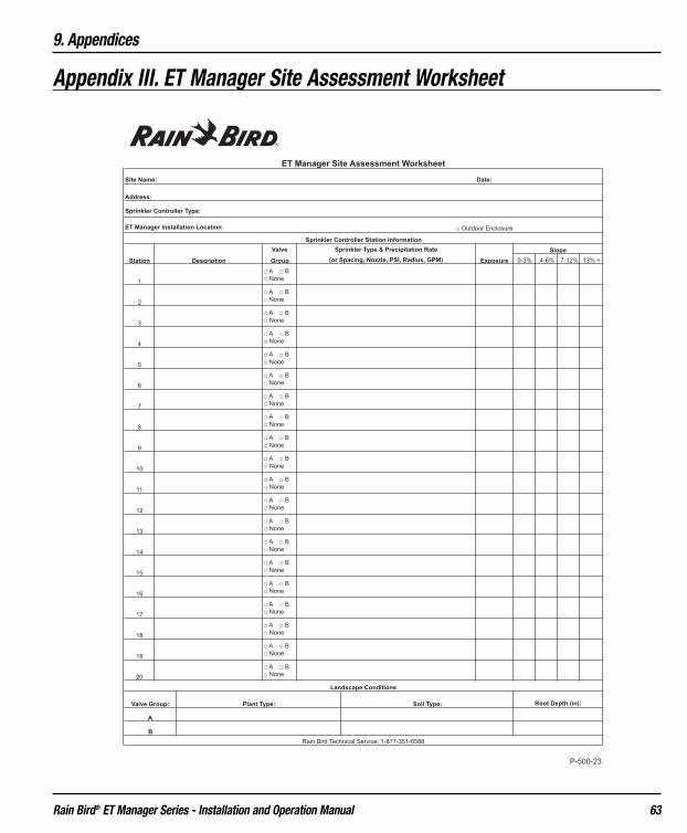
9. Appendices
Rain Bird® ET Manager Series - Installation and Operation Manual 63
Appendix III. ET Manager Site Assessment Worksheet

9. Appendices
Rain Bird® ET Manager Series - Installation and Operation Manual 64
Appendix IV. Soil Texture by Feel DiagramSource: “A Flow Diagram for Teaching Texture-by-Feel Analysis” published in the Journal of AgronomicEducation by Steve J. Thien, Vol. 8, 1979. pp. 54-55.

9. Appendices
Rain Bird® ET Manager Series - Installation and Operation Manual 65
Appendix V. Calculating Precipitation Rates and Station Run Times
Precipitation RateEach station in a sprinkler system applies water at a given rate, known as the precipitation rate, expressed in inchesper hour. Precipitation rates vary based on the sprinkler type, spacing, nozzle, pressure, and sprinkler layout. Thereare three ways to determine the precipitation rate:
Option 1: Refer to the manufacturer sprinkler performance charts.Option 2: Use the industry accepted precipitation rate formula:
96.25 x Sprinkler Gallons per Minute (gpm)Precipitation rate (in/hr) = ———————————————————————————
Sprinkler Head Spacing (ft) x Sprinkler Row Spacing (ft)
Note: 96.25 is a constant used as a conversion factor
Option 3: Perform a catch can test to measure the amount of water applied by the sprinklers in a given timeperiod. The following formula
Average Catch Can Value 60 MinutesPrecipitation rate (in/hr) = ——————————————————- x ———————
Catch Can Test Duration (minutes) 1 Hour
Station Run TimeStation run time is based on the Irrigation Amount and precipitation rate. For example, if the Irrigation Amount is0.5” and the precipitation rate of the sprinklers for a station is 1.5” per hour, the station must run for 20 minutes toapply 0.5” of water.
You can calculate the station run time using the precipitation rate and the Irrigation Amount:
Irrigation Amount x 60 Run Time = ———————————————
Precipitation Rate
Note: The station run time may need to be adjusted based on the sprinkler distribution uniformity.

9. Appendices
Rain Bird® ET Manager Series - Installation and Operation Manual 66
Appendix VI. ET Manager Settings Worksheet

9. Appendices
Rain Bird® ET Manager Series - Installation and Operation Manual 67
Appendix VII. Sprinkler Controller Programming Worksheet

9. Appendices
Rain Bird® ET Manager Series - Installation and Operation Manual 68
Appendix VIII: ET Manager Installation Checklist

9. Appendices
Rain Bird® ET Manager Series - Installation and Operation Manual 69
Appendix IX. ET Manager Status Report Worksheet

9. Appendices
Rain Bird® ET Manager Series - Installation and Operation Manual 70
Master valve and pump control can be utilized withyour ET Manager. Please carefully read the given meth-ods below when using master valve and pump controlwith your ET Manager.
Master Valve Control There are three options for using the sprinkler mastervalve:
1. Use two isolation relays and a separate com-mon. This is the safest scheme to use thesprinkler master valve.
2. Use a separate common only. This scheme isconstrained because the master valve will turnon with every sprinkling cycle, even whenvalves are not actually watering.
3. Use Valve Group A only by routing the samecommon to the master valve and the sprinklervalves. This method is limited to using onlyone valve group.
See Figures 18, 19, and 20 for the wiring diagrams dis-playing Options 1 through 3.
Appendix X. Master Valve and Pump Control Installation with ET Manager
Figure 18. ET Manager Master Valve Wiring Diagram using Isolation Relays

9. Appendices
Rain Bird® ET Manager Series - Installation and Operation Manual 71
Figure 19. ET Manager Master Valve Wiring Diagram using Separate Common

9. Appendices
Rain Bird® ET Manager Series - Installation and Operation Manual 72
Pump ControlPump control can be utilized, but it is limited to work-ing with one Valve Group only.
Pump Control Warning: The ET Manager must NOTbe used to control a pump when more than one valvegroup is used. The result will be that the pump turns onwithout a valve being on.
Figure 20. ET Manager Master Valve Wiring Diagram using Valve Group A Only
10. Glossary
Rain Bird® ET Manager Series - Installation and Operation Manual 73
10. GlossaryAccuracy: The ET Manager looks at the last two weeksof weather signals and reports the accuracy of theweather signal. An accuracy level less than 65% willcreate an attention condition.
Attention Indicator Light: A yellow light signals a con-dition that you should be aware of. An attention mes-sage is displayed on the Home screen.
Automatic Mode: Automatic mode is the standardControl Mode setting. In this mode all automatic func-tions are active and your ET Manager will operate asprogrammed.
Automatic Window: The Automatic Window is pro-grammed to match the first start time programmed inyour sprinkler controller, and to stay open until yoursprinkler controller has completed watering all cycles.A status message on the Home screen indicates whenthe Automatic Window is open. Watering is eitherinterrupted or enabled during the Automatic Window. If watering is enabled (Valve Indicator Light(s) is green),a current sensor is used to verify that the sprinkler con-troller operates during the time period.
Available Watering Days: The days available forwatering are programmed in your ET Manager oryour sprinkler controller. Typically Available WateringDays are set to “all” or everyday.
Clear Data: The ET Manager stores two weeks ofweather signal data. Records can be cleared if needed.Clearing the data will erase all of the stored data.Clearing data will also reset moisture levels to zero.Clearing Data will not change any settings.
Control Mode: Normally your ET Manager should beset to operate in the Automatic mode. Other modesinclude Disabled and Historical ET. This menu allowsyou to select the control mode.
Crop Coefficients (Kc): A factor percentage to modifyETOS based on a specific plant type. It is used to adjustan ET value to meet the specific needs of a plant, ETOSx KC = ETC. There are both local and seasonal varia-tions in KC values.
Cursor: The “�” symbol indicates the current cursorlocation.
Daily Window: The Daily Window is a period of timeprogrammed in your ET Manager corresponding to thetime period the sprinkler controller is programmed towater BUT NOT based on ET control. Watering isallowed every day during the Daily Window. When theDaily Window “opens” it enables or allows watering onboth Valve Groups A and B. The Daily Window periodoperates outside the Automatic Window.
Decoder Failure: Your ET Manager uses signal decoderto receive the weather signal. The Attention Light willcome on and “Decoder Failure” will appear if your ETManager is experiencing decoder problems.
Disabled Mode: The ET Manager can be disabled. Thiscan be selected from the Control Mode menu. WhenDisabled all automatic functions are suspended. Theweather signal will continue to be received and logged,ET will be calculated, while all outputs are disabled andthe indicator lights will be off.
Effective Rain Settings: Effective rain is the amount ofrain that is an effective or available source of water forthe plant. When rainfall amounts and intensities areextreme, not all rainfall will stay within the root zone.To restrict the amount of rain recognized by the system,two effective rainfall limits should be programmed:Max Hourly Rain and Saturation Allowance (see defini-tions for Max Hourly Rain and Saturation Allowance).
Elevation: Your ET Manager uses elevation above sealevel when calculating ET.
Enable: The ET Manager uses this Output Method tocontrol the days a sprinkler controller is allowed to water.It will enable watering when it is needed. This modebypasses the common output of the controller.
10. Glossary
Rain Bird® ET Manager Series - Installation and Operation Manual 74
Enable A then B: This Output Method operates thesame as the Enable method with one significant differ-ence, where watering is allowed on only one valvegroup per day. Watering on the other valve group willbe delayed until the following day.
ET: An abbreviation for evapotranspiration (see evapo-transpiration).
ET and Rain Pulse: An Output Method that delivers ETand rain data to a compatible sprinkler controller. Adry contact switch closure represents 0.01 inches of ET.The rain output signals 0.01 inches of rain with a drycontact switch closure. Compatible sprinkler con-trollers use this information to make watering schedul-ing decisions.
ETc: Evapotranspiration calculated to include land-scape adjustments and crop coefficients.
ET Manager (Model ETMi): An accessory to a sprin-kler controller to automate watering schedules basedon real-time weather data ensuring watering occursonly as needed.
ET Manager 120-volt AC Plug-in Transformer635640 (Model ETMi-TRAN): An optional ETManager power source is the plug-in transformer andit draws power from a standard 120-volt AC outlet.
ET Manager Outdoor Enclosure (ETMi-OE): ETManager outdoor enclosure option made of industriallockable fiberglass, a NEMA 4X cabinet with 110-voltAC outlets.
ET Manager Programming Software (ETM-PS): TheET Manager Programming Software is a software pro-gram that simplifies ET Manager programming. TheETM-PS allows you to connect your ET Manager to apersonal computer to perform several key functions.
ET Manager Scheduler: The Rain Bird ET ManagerScheduler software program uses site specific informa-tion to help you prepare a watering schedule that canbe programmed in your sprinkler controller. The ETManager Scheduler can also be used to help in deter-mining initial settings for your ET Manager.
ET Manager Settings: Your ET Manager operationrequires programming specific settings. Most of theprogrammable settings are site specific.
ETMi: Model number for the ET Manager controllerinterface, for indoor use only.
ET Manager Remote Antenna Kit (ETMi–ANT): If theweather signal is regularly missed with the built-inantenna, the ET Manager Remote Antenna Kit may beconnected and mounted in a location for better recep-tion.
ET Pulse with Weather Interrupt: An Output Methodthat delivers ET to a compatible sprinkler controllerand interrupts watering during high winds, freezingtemperatures and rainfall. A dry contact switch closuresignal represents 0.01inches of ET. A second outputacts as a sensor interrupt to prevent watering if any oneof the three Weather Interrupt conditions occurs.Compatible sprinkler controllers use this informationto make watering scheduling decisions.
Evapotranspiration or ET: A measurement of thewater that evaporates from the soil and transpires froma plant. ET represents the total moisture loss from theroot zone.
Exposure: Environmental exposures, such as sun expo-sure, high winds, or shade, can increase or decrease therate of evaporation. Exposure areas that would increasethe rate of evaporation may need longer station runtimes, while exposure areas that would decrease therate of evaporation may be fine with shorter station runtimes.
Historical ET: The ET Manager can be set to operateusing historical ET data, instead of the weather signaldata. If a problem occurs and the ET Manager is notreceiving the weather signal, it will continue to operateusing historical ET data as a default ET. This settingrepresents an average daily ET for each month.

10. Glossary
Rain Bird® ET Manager Series - Installation and Operation Manual 75
Historical ET Mode: Historical ET mode uses an aver-age daily ET for each month programmed in the ETManager instead of the weather signal data to operate.In the Historical ET Control Mode information from theweather signal is ignored. If there is an on-site raingauge, the rain data collected will be used to adjustwatering schedules.
Hour Manual Override: Your ET Manager can be tem-porarily “Overridden” to allow manual watering. Eachtime the Override is pressed, one more hour is added tothe Override mode. The “Hour Manual Override” statusmessage indicates when an Override has been startedand the amount of time left before it reverts back to thenormal operating mode.
Humidity: Relative humidity is measured at the weath-er station and is included in the weather signal to cal-culate ET.
Information Log: Your ET Manager reports importantinformation such as: the last time the sprinklerswatered, how many times the sprinklers watered, howmuch water has been applied, the last weather inter-rupt and signal accuracy. Find these values in the infor-mation log menu.
Irrigation Amount: The amount of water, in inches (ormm) applied to your landscape by each wateringcycle(s). This amount of water must evaporate beforethe ET Manager will allow watering to occur. TheIrrigation Amount is based on your soil type and theplant root depth.
Irrigation Status: You can view the details of the currentMoisture Levels for Valve Group A and B, Moisture Levelgraphs, ET, and rainfall information stored over the lasttwo weeks in the Irrigation Status menu.
Landscape Adjustment Percentage: The LandscapeAdjustment Percentage is used to adjust for site-spe-cific landscape needs for Valve Group A and ValveGroup B. The Landscape Adjustment Percentage isapplied to the calculated ET, and effects the currentMoisture Levels for Valve Groups A and B.
Last Interrupt: The Last Interrupt displays the cause,date, and time of the last weather interrupt. Weatherinterrupts occur during irrigation when specific condi-tions are met. Weather interrupts can be programmedfor temperature, wind, or rain conditions.
LCD Display: The graphical display is used to view cur-rent operating conditions, monitor status, view settings,and make programming changes.
Look-Ahead Feature: If Available Days have beenrestricted and not set to “All,” the ET Manager looksahead each day to determine if watering should occureven though the Moisture Level has not reached zero.
Master Valve Control: Master valve control can be uti-lized with your ET Manager, refer to Appendix X.
Max Hourly Rain: The Maximum Hourly Rain is themaximum amount of rain that will be accepted eachhour in the soil moisture level, see Effective Rain.
Menu Path: Menu paths are found throughout themanual to show which items within the menu and sub-menus need to be selected to access key information orto adjust settings.
Example of a Menu path: Main Menu �Settings �Irrigation Status �“A” Moisture Level
Missing Data: The ET Manager checks and stores datareceived in the weather signal. If data is missed thenET is calculated using a data replacement formula. Ifsignal reception accuracy is less than 65% then theMissing Data alert will come on due to 35% of missingdata.
Moisture Level: Moisture is depleted from the soil dueto evaporation. Rain and water from the sprinkler sys-tem replaces this water. Your ET Manager computes thecurrent Moisture Levels for Valve Group A and ValveGroup B. When the Moisture Level reaches 0, wateringis enabled and the sprinkler controller is allowed towater.

10. Glossary
Rain Bird® ET Manager Series - Installation and Operation Manual 76
Navigation Buttons: The Ã, Œ, Õ, or À naviga-tion buttons are used to position the cursor at thedesired location and navigate through the ET Managermenus.
No Historical ET Data: The ET Manager uses a histori-cal ET database as a backup in the event weather signalservice is not available. Historical ET data is pro-grammed in your ET Manager based on local condi-tions. If your ET Manager is not programmed with his-torical ET data, a No Historical ET Data attention mes-sage will appear on the Home screen.
No Paging Signal: The ET Manager periodically verifiesthe presence of the Paging Signal. If the paging signal isnot detected after a period of time the AttentionIndicator Light will come on and the No Paging Signalis displayed on the Home screen.
No Power: The ET Manager needs power to operate.The battery is used only to keep time during a poweroutage and keep the display screen active. If there is nopower, the Attention Indicator Light will not come on,but a No Power message will appear on the Homescreen.
No Signal Service: Your Weather Reach Signal Provider(WRSP) can send a “No Signal Service” signal to cancelweather signal reception. Typically this would happenonly if the terms of the service agreement were not met.
No Water Day: Available watering days can be pro-grammed in your ET Manager. If the current day hasbeen set to “Off,” watering will not be enabled regard-less of the current Moisture Levels. The No Water Daystatus message indicates that the current day has beenset to “Off.”
No Watering Detected: Your ET Manager may notdetect watering if your ET Manager has not been prop-erly wired or the sprinkler controller has not been prop-erly programmed. “No Watering Detected” appears onthe Home screen and the Attention Indicator Lightturns on when this condition occurs.
No Weather Data: If your ET Manager has not receiveda weather signal for more than 25 hours the AttentionIndicator Light comes on and this message will be dis-played on the Home screen.
Output Method: To accommodate a variety of sprin-kler controllers, the ET Manager has four output meth-ods: Enable, Enable A then B, ET and Rain Pulse, or ETPulse with Weather Interrupt. Enable is the most com-mon Output Method used.
Override: The override button temporarily bypasses ETManager control, allowing valve relays to close andenabling watering regardless of the current ET Managerstatus. Override watering is adjusted in hourly incre-ments.
Password: Access to the ET Manager setting featurescan be protected by an optional user defined numericpassword (from 1 to 255, or “none”).
Plant Type: It is important to understand what planttypes (turf grass types, shrubs, trees, and groundcover)are included in the landscape. These different planttypes use water at different rates, requiring differentIrrigation Amounts and Landscape AdjustmentPercentages.
Precipitation Rate: The rate at which water is appliedto the landscape, or the precipitation rate, is measuredin inches per hour.
Provider Interrupt: The Weather Reach Signal Provider(WRSP) can send a signal to interrupt watering. Thismay be necessary during an emergency condition inthe community requiring watering to be suspended tolimit the demand on the community water system. Asa service, your WRSP may also watch weather forecastsand choose to interrupt watering. A Provider Interruptlasts for 24 hours.
Pump Control: Pump control can be utilized with yourET Manager using one Valve Group only, refer toAppendix X.

10. Glossary
Rain Bird® ET Manager Series - Installation and Operation Manual 77
Rain Interrupt 24 Hours: Rainfall over the last 24hours that is at or above the Rain Interrupt 24 Hour set-ting will cause a Weather Interrupt. The weather inter-rupt is cancelled once the total rainfall in the last 24hours drops below the Rain 24 Hour setting.
Rain Interrupt 1 Hour: Rainfall over the last hour thatis at or above the Rain Interrupt 1 Hour setting willcause a rain interrupt. The weather interrupt is can-celled once the total rainfall in the last hour dropsbelow the Rain 1 Hour setting.
Rain Region: Like the weather region number, a rainregion number represents an area where customersshare data. Within an area, one on-site tipping bucketrain gauge is used to share localized rain data amongET Manager customers, allowing for a more accuraterepresentation of local rain. Your Weather Reach SignalProvider (WRSP) broadcasts rain region data.
Rain Source: The rain source is the source of rain datafor the ET Manager. Rain data comes from the weathersignal, from an optional rain gauge, or from a rainregion.
Rain Tip Input Failure: Your ET Manager can use real-time rain data collected from an optional on-site raingauge. If you are using a rain gauge to collect rain dataand “Rain Tip Input Failure” appears on the Homescreen, your ET Manager is indicating a problem withthe Rain Tip wire terminal, installation, or operation ofthe on-site rain gauge.
Restore Defaults: If ET Manager’s programmed set-tings have been saved as default settings, and the cur-rent settings are changed, by restoring defaults the orig-inal saved default settings are restored. If settings werenot saved as defaults, restoring defaults restores the fac-tory default settings.
Root Depth: The soil reservoir capacity is directly relat-ed to plant root depth. Deeper roots increase theamount of water available to the plants. To promote adeep healthy root system, best horticultural practicesrecommend less frequent, deep watering. Use a shovelor soil probe to determine root depth.
Saturation Allowance: The amount of rain it takes tosaturate the soil after satisfying the Irrigation Amountbefore run-off occurs. Unique Saturation Allowancesettings can be made for Valve Group A and ValveGroup B, and are typically programmed as half theIrrigation Amount.
Save Defaults: The current ET Manager settings can besaved. Once saved, you can restore saved settings if set-tings have been changed incorrectly by using RestoreDefaults.
Serial Number: The serial number of your ET Manageris displayed on the LCD contrast screen and is visibleunder the terminal cover on the left side of your ETManager.
Set Signal Provider Code: If the attention message,“Set Signal Provider Code” appears on the Homescreen, your ET Manager has been installed, but notprogrammed with the appropriate Signal ProviderCode. The Signal Provider Codes can be accessed fromwww.rainbird.com/etmanager and the ET ManagerScheduler.
Signal Crop Coefficient (or Signal Kc): Crop coeffi-cients are used to modify ET to meet the specific needsof the landscape. The Weather Reach Signal Provider(WRSP) includes a crop coefficient value in the weathersignal. You can decide to “Use” or “Ignore” this adjust-ed value to adjust ET in the Advanced Settings inIrrigation Control.
Signal Provider Code: Your ET Manager must be pro-grammed to receive information from your specificWeather Reach Signal Provider (WRSP). A SignalProvider Code is unique for your WRSP and is neces-sary for your ET Manager to receive a weather signal.The code consists of 10 different numbers and these 10numbers are labeled A-J. The Signal Provider Codescan be accessed from www.rainbird.com and the ETManager Scheduler program.
Site Assessment: A site assessment should be complet-ed to determine site-specific conditions which affectprogrammable settings in ET Manager and sprinklercontroller.

10. Glossary
Rain Bird® ET Manager Series - Installation and Operation Manual 78
Slope: When sprinklers apply water faster than the soilcan absorb it, water can run-off. Sloping landscapesincrease the chance of run-off occurring.
Smart Control: The smart control term is used to des-ignate water efficient systems which operate with yoursprinkler system by calculating the evapotranspirationrate, or soil moisture.
Soil: Soil is a habitat for soil organisms and plant roots.It functions as a storehouse for nutrients and a waterreservoir. It contains and supplies water, oxygen, nutri-ents, and provides mechanical support for plantgrowth.
Sprinkler Controller: A sprinkler controller is an elec-tronic timer that activates automatic sprinkler controlvalves within a sprinkler system.
Sprinkler System: A sprinkler system delivers water toa landscape and consists of piping, sprinkler valves,sprinkler heads, and a sprinkler controller. Rain andwater from the sprinkler system replaces water used inthe landscape.
Station: Stations on a sprinkler controller are connect-ed to specific valves that are activated according to yourET Manager. Each station should have plants with sim-ilar water requirements within its area. Stations arealso referred to as “zones.” Stations must be assigned tospecific ET Manager Valve Groups A, B, or none.
Temperature Interrupt: If the hourly weather signalcontains air temperatures that reach the TemperatureInterrupt setting, watering is interrupted. The weatherinterrupt is cancelled once the air temperature risesabove the programmed interrupt setting received in thehourly weather signal.
Terminal Cover: The terminal cover protects the wireterminal connections on your ET Manager. To accessthe wire terminals, the terminal cover will have to beremoved.
Test Counter: The Test Counter registers every signalreceived, increasing from 1 to 255 counts. If 255 signalsare received and counted, the Test Counter will reset to 0.
Tipping Rain Gauge (Model ETM-RG): A Rain Birdapproved, optional on-site tipping rain gauge (1mm/tip) with 30' cable can be connected to the ETManager. The on-site rainfall value can be used inplace of the rainfall value broadcast in the weathersignal to provide accurate on-site rain data.
Units: The ET Manager can calculate and display val-ues in either English or Metric units.
Valve Groups A and B: Your ET Manager controls twoValve Groups (A and B) by enabling sprinkler controlleroutput to the valve common. Each valve group musthave separate common wires to the valves in the group.For example, lawn valves could be in Valve Group A andshrubs valves in Valve Group B.
Valve Group A & B Indicator Lights: There is oneIndicator Light for each valve group, A and B. A greenlight indicates watering is enabled, allowing the sprin-kler controller to activate the valve. A red light indicateswatering is suspended or interrupted until watering isneeded.
Water Window: The ET Manager Water Windows, theAutomatic and Daily Windows, must be synchronizedwith the watering times set in your sprinkler controller.The Watering Widows will not start a watering cycle butare used by the ET Manager to control watering duringthat programmed period of time.
Weather Info: You can view detailed weather informa-tion and graphs of the current weather conditions. Theweather info is stored for fourteen days.
Weather Reach Signal Provider (WRSP): The role ofyour Weather Reach Signal Provider (WRSP) is toretrieve weather information from local weather sta-tions and send the weather signal to your ET Manager.
Weather Reach Water Management System: TheWeather Reach Water Management System automatescommercial and residential sprinkler schedules usingreal-time weather conditions which are sent to your ETManager via your local Weather Reach Signal Provider(WRSP).

10. Glossary
Rain Bird® ET Manager Series - Installation and Operation Manual 79
Weather Region: The weather region number repre-sents a weather station assigned by the Weather ReachSignal Provider (WRSP). The weather region you pro-gram in your ET Manager should correspond to aweather station that closely represents the location ofthe ET Manager. The WRSP assigns each weather sta-tion a weather region number.
Weather Signal: A Weather Reach Signal Provider(WRSP) retrieves weather information from localweather stations. The information is broadcast as aweather signal via a paging radio frequency to your ETManager. The weather signal contains the most recentweather conditions including: solar energy, tempera-ture, wind, humidity, and rainfall.
Wind Adjust: The wind speed measurement includedin the weather signal can be scaled by a percentage tocompensate for variations in prevailing conditionsusing the wind adjust setting.
Wind Interrupt: If the hourly weather signal containswind speeds that reach the Wind Interrupt setting,watering is interrupted. The Weather Interrupt is can-celled once the wind speed decreases below the pro-grammed Wind Interrupt setting.
WRSP: An abbreviation for Weather Reach SignalProvider.
Rain Bird’s Professional Customer Satisfaction PolicyRain Bird will repair or replace at no charge any Rain Bird professional product that fails in normal use within the warranty periodstated in the Rain Bird Landscape Irrigation Products Catalog. You must return said product to the dealer or distributor where youbought it. Product failures due to acts of God including without limitation, lightning and flooding, are not covered by this warranty.
This commitment to repair or replace is our sole and total warranty.
Implied warranties of merchantability and fitness, if applicable, are limited to one year from the date of sale.
We will not, under any circumstances be liable for incidental or consequential damages, no matter how they occur.
The ET Manager comes with default settings. These settings can be overridden when a Rain Bird Distributor programs site specificsettings. Settings entered by the Rain Bird Distributor are programmed as probable initial settings. Many conditions affect each ofthe above settings. The Installer, Distributor, Weather Signal Provider or Rain Bird makes no guarantee that these settings or thedefault settings correctly meet the needs for any specific site. The Owner will need to adjust settings to meet specific site condi-tions.
The Weather Reach Signal Provider (WRSP) accesses weather data from local weather stations and contracts with a paging servicecompany. The WRSP operates independent of the Installer, Distributor, paging company and Rain Bird. Neither the Installer, nei-ther the paging company, neither Distributor nor Rain Bird are responsible for the weather data transmitted by the WRSP. Weatherconditions can vary; the WRSP does not represent the weather signal data to precisely represent actual site conditions. The Ownerwill need to monitor site conditions and adjust the sprinkler system to meet the water requirements of the landscape. By installingthe ET Manager, the Owner agrees to hold all above parties harmless in the event any condition arising from the use of this devicecauses any damage.
Rain Bird Corporation6991 E. Southpoint RoadTucson, AZ, 85706, U.S.A.Phone: (520) 741-6100 Fax: (520) 741-6522
Technical Service and Support (800) RAINBIRD (U.S. & Canada only)
Rain Bird Corporation970 W. Sierra Madre Avenue Azusa, CA,91702, U.S.A.Phone: (626) 812-3400 Fax: (626) 812-3411
Specification Hotline(800) 458-3005 (U.S. & Canada only)
Rain Bird International, Inc.P.O. Box 37Glendora, CA 91740-0037, U.S.A.Phone: (626) 963-9311 Fax: (626) 852-7343
www.rainbird.com
D37377C
The Intelligent Use of Water™ -- Visit www.rainbird.com to learn about our efforts
® Registered trademark of Rain Bird Corporation.© 2007 Rain Bird Corporation 4/07