installation manual lb device - the molecular …mmrc.caltech.edu/lb...
TRANSCRIPT
Installation Manual
LB Device
KSV 2000, 5000, Minitrough & Minimicro
Revision 1.1

Table Of Contents
1. INTRODUCTION------------------------------------------------------------------------- 1
2. CONTENTS CHECKLIST------------------------------------------------------------- 2
3. MECHANICAL INSTALLATION ---------------------------------------------------- 3 3.1. General --------------------------------------------------------------------------------3 3.2. KSV 2000------------------------------------------------------------------------------4 3.3. KSV 5000------------------------------------------------------------------------------7 3.4. KSV Minitrough------------------------------------------------------------------- 10 3.5. System 3 ----------------------------------------------------------------------------- 12 3.6. System 4 ----------------------------------------------------------------------------- 12 3.7. KSV Minimicro -------------------------------------------------------------------- 13
4. LAYERBUILDER -----------------------------------------------------------------------15
5. SOFTWARE INSTALLATION ------------------------------------------------------16 5.1. LayerBuilder Driver Installation ---------------------------------------------- 19
6. DIMENSIONS----------------------------------------------------------------------------22 6.1. KSV 2000 System 1 and LayerBuilder --------------------------------------- 22 6.2. KSV 2000 System 2 --------------------------------------------------------------- 23 6.3. KSV 2000 System 3 --------------------------------------------------------------- 24 6.4. KSV 5000 System 1 --------------------------------------------------------------- 25 6.5. KSV 5000 System 2 --------------------------------------------------------------- 26 6.6. KSV 5000 System 3 --------------------------------------------------------------- 27 6.7. KSV Minitrough System 1 ------------------------------------------------------ 28 6.8. KSV Minimicro System 1-------------------------------------------------------- 29
7. CONTACT INFORMATION----------------------------------------------------------30
1
1. Introduction This manual describes the installation procedure for the LB devices. Due to the modular design of the LB many possible variations exist and so the user can choose exactly what is necessary for their use. It is also possible to first order the basic unit and then later order further modules. Some examples of modules that can be added are a minicab cabinet, a horizontal dipping clamp, a surface potential probe and thermostation. Please contact a local distributor or visit KSV Instruments online at www.ksvltd.com for further information. As this manual contains information only concerned with the installation please see the LB software manual and the device-specific manual for information on calibration, measurement taking or data analysis.
2
2. Contents Checklist The LB device is delivered in one crate. Unpack the crate carefully and check to see that it contains the appropriate items. All LB devices come with the following.
LayerBuilder Frame Stand(s) Barrier drive system Balance Wilhelmy plate 9-pin cable 15-pin cable Power cable Manual Software Monolayer Kit
The different systems have different troughs available as well as other additional devices. System 1:
Flat trough
System 2: Trough with well Dipper Second 15-pin cable
KSV 2000 and 5000 System 3: Alternate trough with half-circle well and two sample compartments Alternate dipper Second barrier drive system Second balance Second Wilhelmy Second 15-pin cable
In the event of damage of any item, notify KSV Instruments Ltd and the freight company immediately. If necessary take pictures of the damaged packaging and/or item at this stage. This will help any insurance claims and speed replacement of damaged items.

3
3. Mechanical Installation 3.1. General
Place the instrument on a vibration free table in an area with low local air currents so that it is lengthwise with the stand at the back. It is helpful if running water and a hot flame source (Bunsen burner) are nearby. Level the instrument by either the tool provided or by filling the trough with water and examining its tilt. The height of each leg can be adjusted individually. Unscrew the nut on the balance to remove the transport cover and place the balance on the stand with the hook hanging freely. Screw the nut back on to fasten the balance. Store the transport cover next to the instrument in order to use it if the instrument needs to be moved. Place the trough next to the barrier drive, make sure that the nut on the barrier drive is aligned with the respective hole on the trough and push the trough and the barrier drive together. Place the barriers on top of the trough so that the bar is pointed towards the barrier drive and goes through the forks. A suitable location for the LB device is a table or a workbench in room with little air currents and minimal vibration. The barrier drives on KSV 2000 and KSV 5000 should be fixed onto the worktable with screws to improve stability. Devices with 15-pin serial cables connect to the back of the LayerBuilder, devices with 9-pin serial cables connect directly to the computer. The LayerBuilder connects to the computer with a USB cable. Take care not to scratch the Teflon surface of the trough. Cleanliness is instrumental in surface chemistry!
4
3.2. KSV 2000
A) System 1
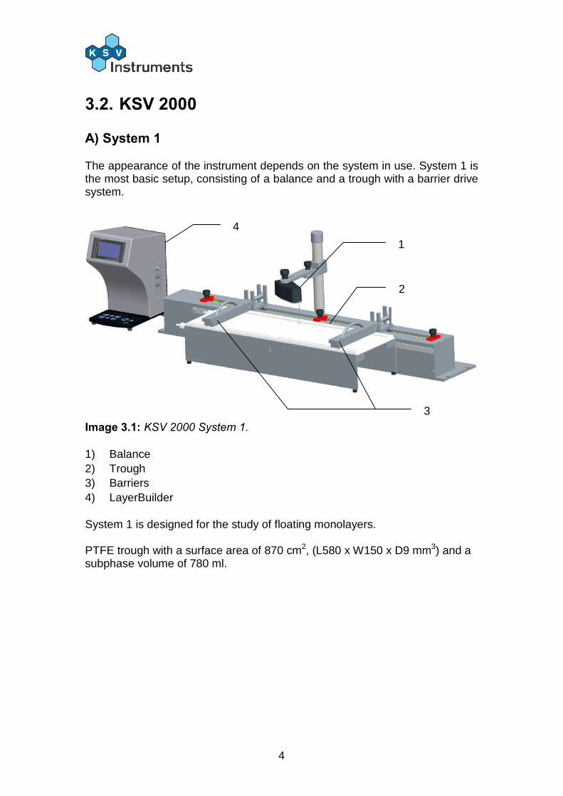
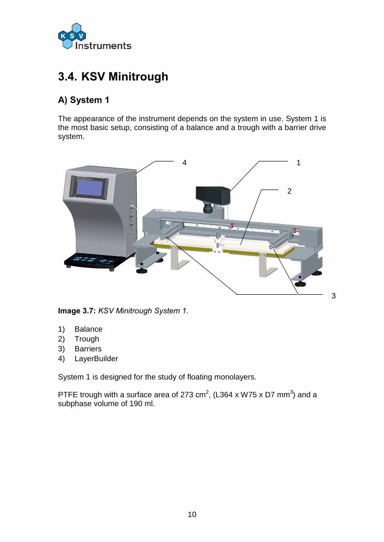
The appearance of the instrument depends on the system in use. System 1 is the most basic setup, consisting of a balance and a trough with a barrier drive system.
Image 3.1: KSV 2000 System 1. 1) Balance 2) Trough 3) Barriers 4) LayerBuilder System 1 is designed for the study of floating monolayers. PTFE trough with a surface area of 870 cm2, (L580 x W150 x D9 mm3) and a subphase volume of 780 ml.
1
2
3
4

5
B) System 2
The System 2 additions over System 1 are the dipper, a second stand for the dipper and a trough with a well.
Image 3.2: KSV 2000 System 2. 1) Balances 4) LayerBuilder 2) Trough 5) Dipper 3) Barriers 6) Well System 2 is designed for the study of floating monolayers and for the deposition of multilayer films of one substance on a solid substrate. PTFE trough with a surface area of 870 cm2, (L580 x W150 x D9 mm3), a dipping well (L37 x W117 x D90 mm3) and a subphase volume of 1172 ml. Unscrew the nut on the dipper and place the dipper on the stand so that the arm of the dipper is pointed down towards the trough. Screw the nut back onto the dipper to fasten the dipper to the stand. Adjust the dipper so that the sample clip holder is centered to the dipping well.
1
2
3
4
5
6
6
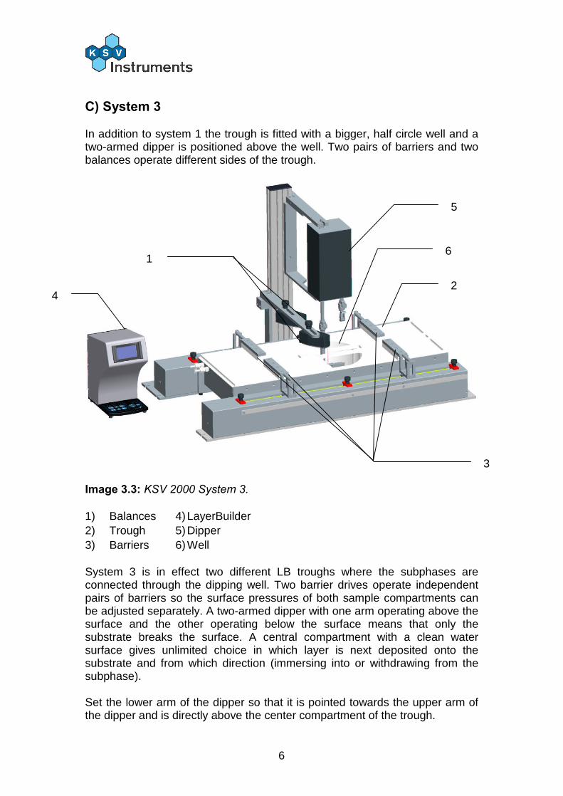
C) System 3
In addition to system 1 the trough is fitted with a bigger, half circle well and a two-armed dipper is positioned above the well. Two pairs of barriers and two balances operate different sides of the trough.
Image 3.3: KSV 2000 System 3. 1) Balances 4) LayerBuilder 2) Trough 5) Dipper 3) Barriers 6) Well System 3 is in effect two different LB troughs where the subphases are connected through the dipping well. Two barrier drives operate independent pairs of barriers so the surface pressures of both sample compartments can be adjusted separately. A two-armed dipper with one arm operating above the surface and the other operating below the surface means that only the substrate breaks the surface. A central compartment with a clean water surface gives unlimited choice in which layer is next deposited onto the substrate and from which direction (immersing into or withdrawing from the subphase). Set the lower arm of the dipper so that it is pointed towards the upper arm of the dipper and is directly above the center compartment of the trough.
1
2
3
4
5
6
7
3.3. KSV 5000
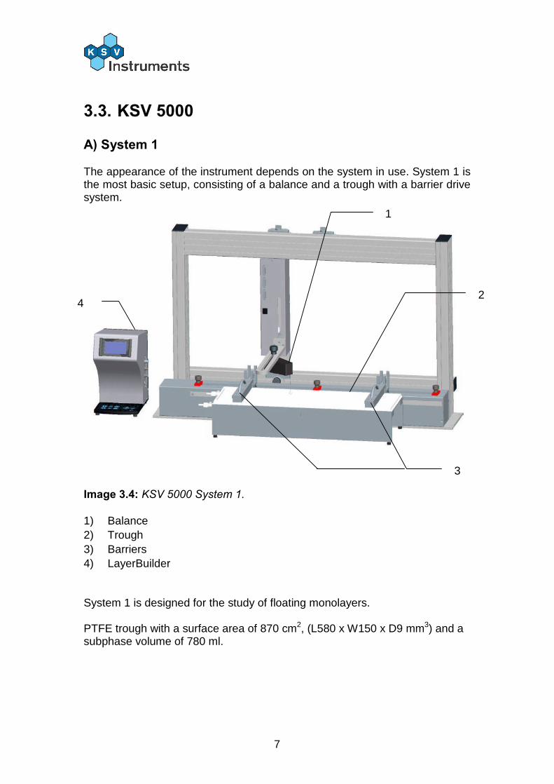
A) System 1
The appearance of the instrument depends on the system in use. System 1 is the most basic setup, consisting of a balance and a trough with a barrier drive system.
Image 3.4: KSV 5000 System 1. 1) Balance 2) Trough 3) Barriers 4) LayerBuilder System 1 is designed for the study of floating monolayers. PTFE trough with a surface area of 870 cm2, (L580 x W150 x D9 mm3) and a subphase volume of 780 ml.
1
2
3
4
8
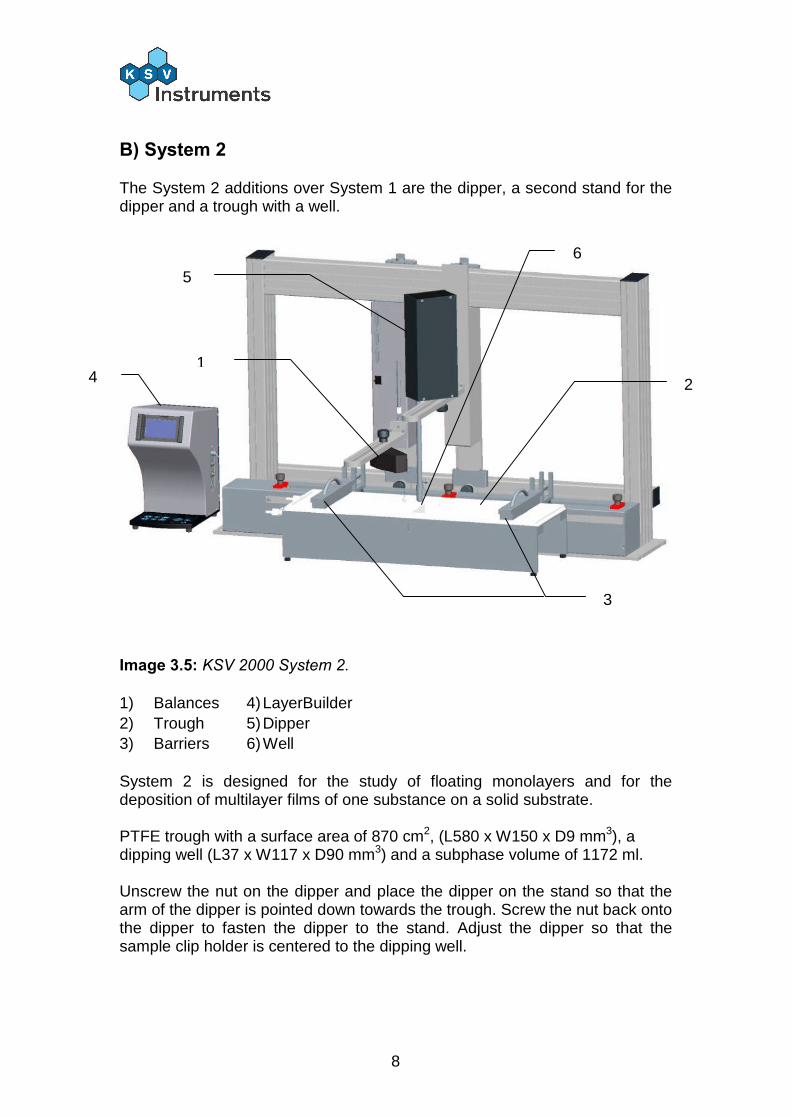
B) System 2
The System 2 additions over System 1 are the dipper, a second stand for the dipper and a trough with a well.
Image 3.5: KSV 2000 System 2. 1) Balances 4) LayerBuilder 2) Trough 5) Dipper 3) Barriers 6) Well System 2 is designed for the study of floating monolayers and for the deposition of multilayer films of one substance on a solid substrate. PTFE trough with a surface area of 870 cm2, (L580 x W150 x D9 mm3), a dipping well (L37 x W117 x D90 mm3) and a subphase volume of 1172 ml. Unscrew the nut on the dipper and place the dipper on the stand so that the arm of the dipper is pointed down towards the trough. Screw the nut back onto the dipper to fasten the dipper to the stand. Adjust the dipper so that the sample clip holder is centered to the dipping well.
1 2
3
4
5
6
9
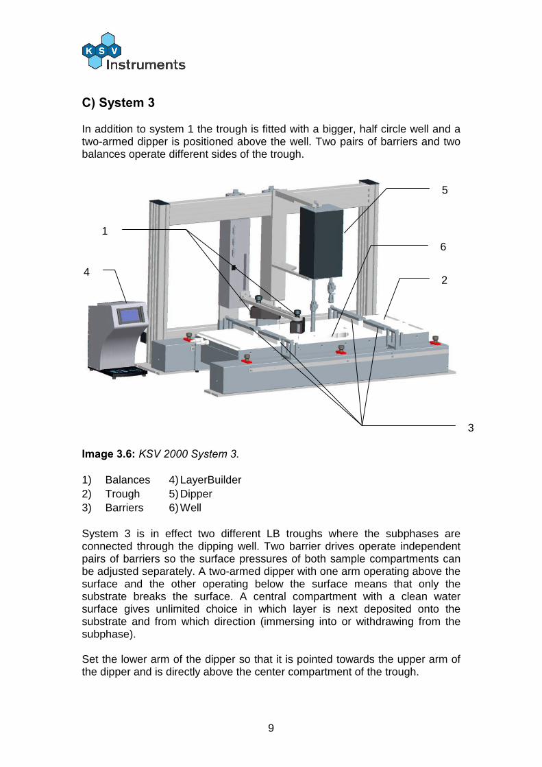
C) System 3
In addition to system 1 the trough is fitted with a bigger, half circle well and a two-armed dipper is positioned above the well. Two pairs of barriers and two balances operate different sides of the trough.
Image 3.6: KSV 2000 System 3. 1) Balances 4) LayerBuilder 2) Trough 5) Dipper 3) Barriers 6) Well System 3 is in effect two different LB troughs where the subphases are connected through the dipping well. Two barrier drives operate independent pairs of barriers so the surface pressures of both sample compartments can be adjusted separately. A two-armed dipper with one arm operating above the surface and the other operating below the surface means that only the substrate breaks the surface. A central compartment with a clean water surface gives unlimited choice in which layer is next deposited onto the substrate and from which direction (immersing into or withdrawing from the subphase). Set the lower arm of the dipper so that it is pointed towards the upper arm of the dipper and is directly above the center compartment of the trough.
1
2
3
4
5
6
10
3.4. KSV Minitrough
A) System 1
The appearance of the instrument depends on the system in use. System 1 is the most basic setup, consisting of a balance and a trough with a barrier drive system.
Image 3.7: KSV Minitrough System 1. 1) Balance 2) Trough 3) Barriers 4) LayerBuilder System 1 is designed for the study of floating monolayers. PTFE trough with a surface area of 273 cm2, (L364 x W75 x D7 mm3) and a subphase volume of 190 ml.
1
2
3
4
11
B) System 2
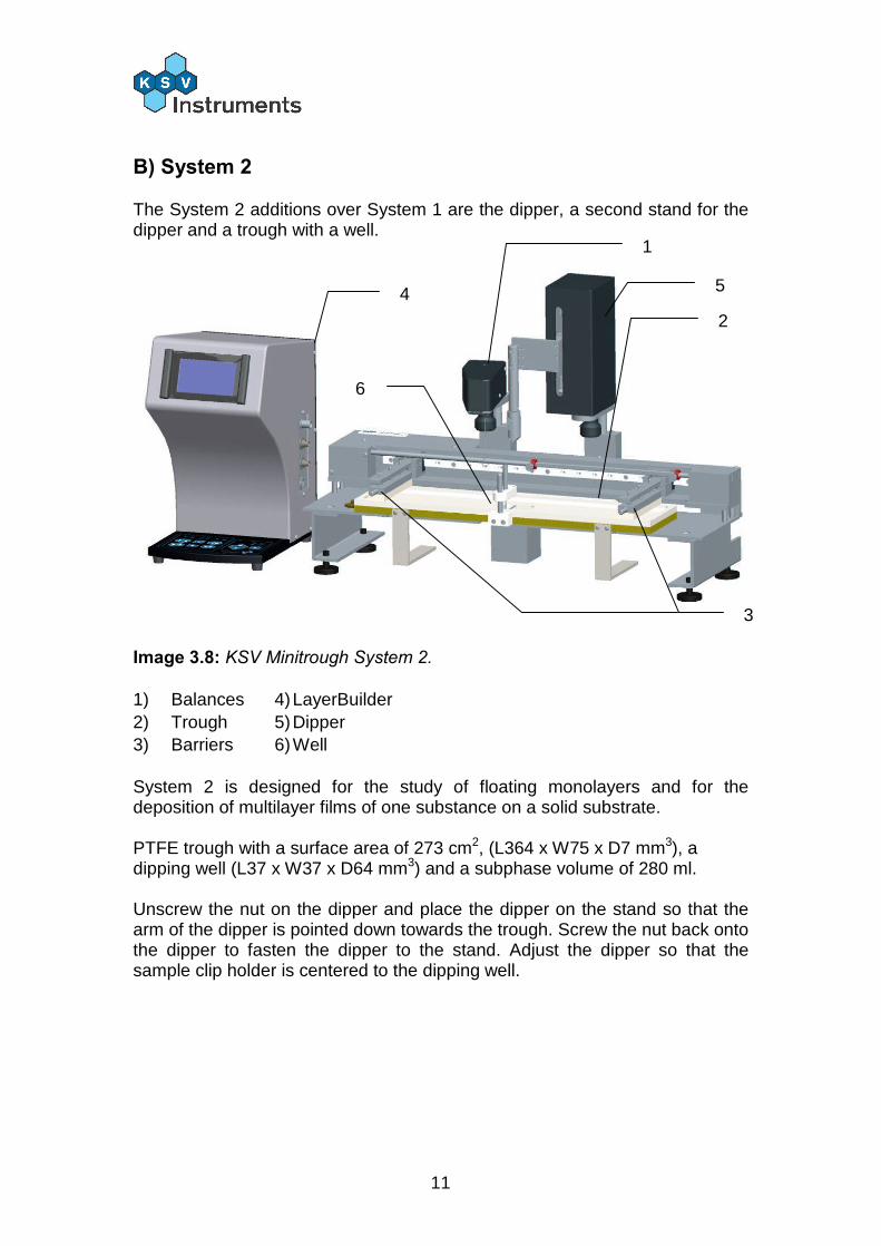
The System 2 additions over System 1 are the dipper, a second stand for the dipper and a trough with a well.
Image 3.8: KSV Minitrough System 2. 1) Balances 4) LayerBuilder 2) Trough 5) Dipper 3) Barriers 6) Well System 2 is designed for the study of floating monolayers and for the deposition of multilayer films of one substance on a solid substrate. PTFE trough with a surface area of 273 cm2, (L364 x W75 x D7 mm3), a dipping well (L37 x W37 x D64 mm3) and a subphase volume of 280 ml. Unscrew the nut on the dipper and place the dipper on the stand so that the arm of the dipper is pointed down towards the trough. Screw the nut back onto the dipper to fasten the dipper to the stand. Adjust the dipper so that the sample clip holder is centered to the dipping well.
1
2
3
4 5
6

12
3.5. System 3 In addition to system 1 the trough is fitted with a quartz window. System 3 is designed for the microscopic study of floating monolayers. It is suitable for all conventional microscopes and inverted fluorescence microscopes.
Image 3.9: KSV Minitrough System 2.
3.6. System 4
In addition to system 1 the trough length is doubled. The dimensions of the trough are surface area of 587 cm2, (L782 x W75 x D7 mm3) and a subphase volume of 290 ml.

13
3.7. KSV Minimicro
A) System 1
The appearance of the instrument depends on the system in use. System 1 is the most basic setup, consisting of a balance and a trough with a barrier drive system.
Image 3.10: KSV Minimicro System 1. 1) Balance 2) Trough 3) Barriers 4) LayerBuilder System 1S is designed for the study of floating monolayers and the study of monolayers with microscopy. It has a PTFE trough with a surface area of 100 cm2, (L195 x W51 x D4 mm3) and a subphase volume of 40 ml. System 1G is designed for the study of floating monolayers and for grazing anlge applications. It has a PTFE trough with a surface area of 170 cm2, (L195 x W85 x D5 mm3) and a subphase volume of 83 ml.
1
2
3
4
14
B) System 2
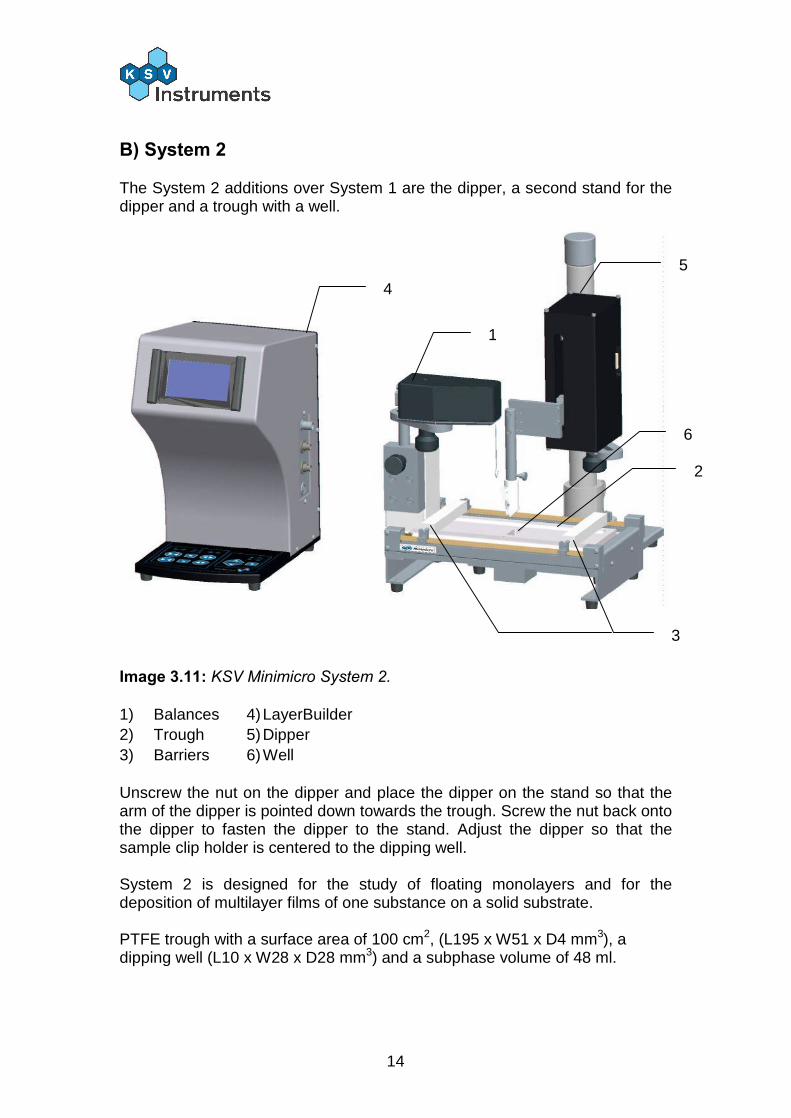
The System 2 additions over System 1 are the dipper, a second stand for the dipper and a trough with a well.
Image 3.11: KSV Minimicro System 2. 1) Balances 4) LayerBuilder 2) Trough 5) Dipper 3) Barriers 6) Well Unscrew the nut on the dipper and place the dipper on the stand so that the arm of the dipper is pointed down towards the trough. Screw the nut back onto the dipper to fasten the dipper to the stand. Adjust the dipper so that the sample clip holder is centered to the dipping well. System 2 is designed for the study of floating monolayers and for the deposition of multilayer films of one substance on a solid substrate. PTFE trough with a surface area of 100 cm2, (L195 x W51 x D4 mm3), a dipping well (L10 x W28 x D28 mm3) and a subphase volume of 48 ml.
1
2
3
4
5
6
15
US
B
DE
V 1
DE
V 2
DE
V 3
DE
V 4
DE
V 5
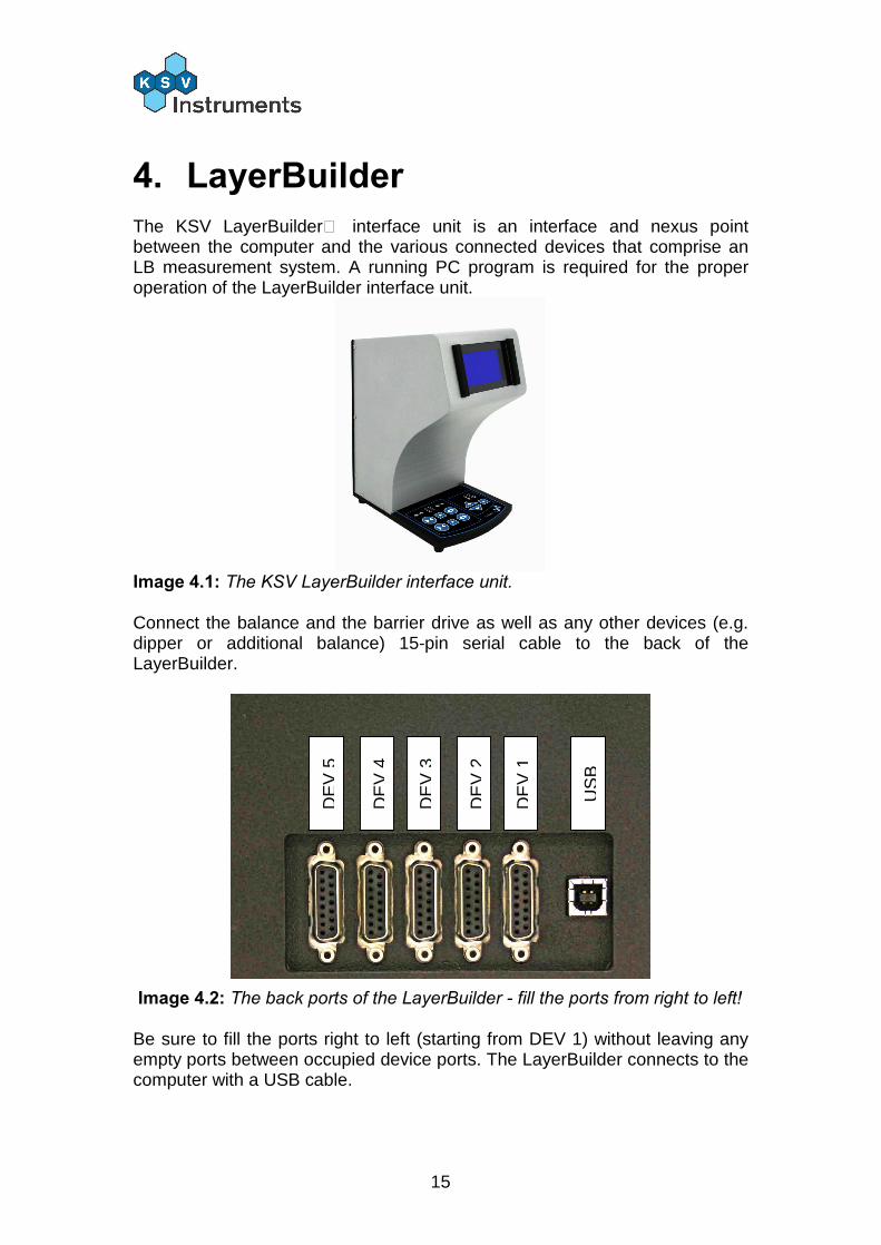
4. LayerBuilder The KSV LayerBuilder™ interface unit is an interface and nexus point between the computer and the various connected devices that comprise an LB measurement system. A running PC program is required for the proper operation of the LayerBuilder interface unit.
Image 4.1: The KSV LayerBuilder interface unit. Connect the balance and the barrier drive as well as any other devices (e.g. dipper or additional balance) 15-pin serial cable to the back of the LayerBuilder.
Image 4.2: The back ports of the LayerBuilder - fill the ports from right to left! Be sure to fill the ports right to left (starting from DEV 1) without leaving any empty ports between occupied device ports. The LayerBuilder connects to the computer with a USB cable.

16
5. Software Installation Insert the LB Installation CD into the CD-Rom drive. Open My Computer from the desktop, select the CD drive (D:\ by default) and double-click on SetupLayerBuilder.exe. The installation will now begin with the following screen.
Press Next to continue.
17
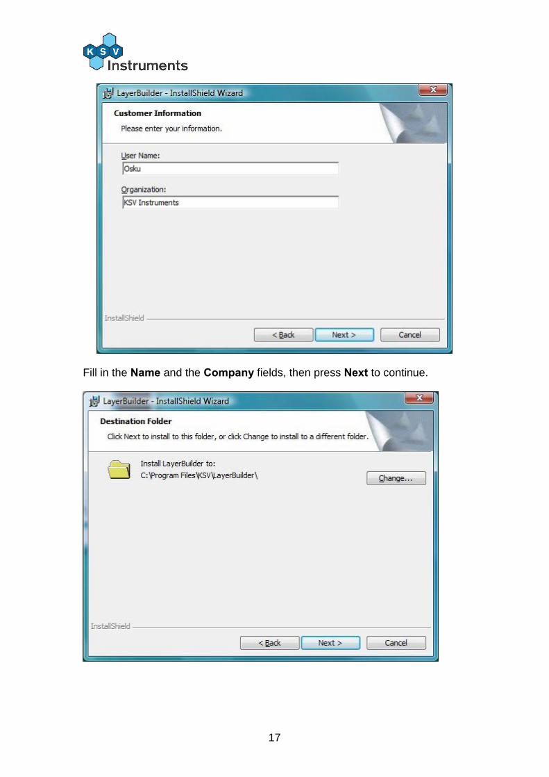
Fill in the Name and the Company fields, then press Next to continue.

18
To install the software in the default directory (recommended) just press Next. To install the software in another location press Browse, select the destination and then press Next.
Press Next to begin installing the files onto the computer. This might take several minutes. Press Finish to complete the software installation process.
19
5.1. LayerBuilder Driver Installation
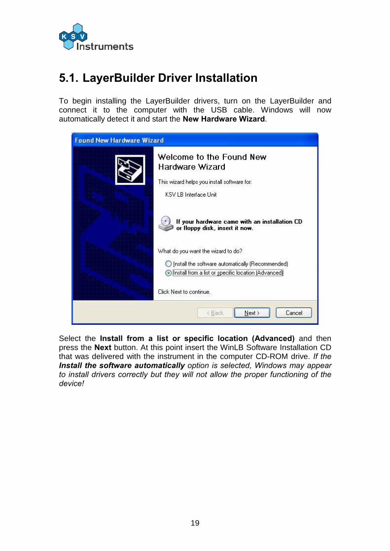
To begin installing the LayerBuilder drivers, turn on the LayerBuilder and connect it to the computer with the USB cable. Windows will now automatically detect it and start the New Hardware Wizard.
Select the Install from a list or specific location (Advanced) and then press the Next button. At this point insert the WinLB Software Installation CD that was delivered with the instrument in the computer CD-ROM drive. If the Install the software automatically option is selected, Windows may appear to install drivers correctly but they will not allow the proper functioning of the device!
20
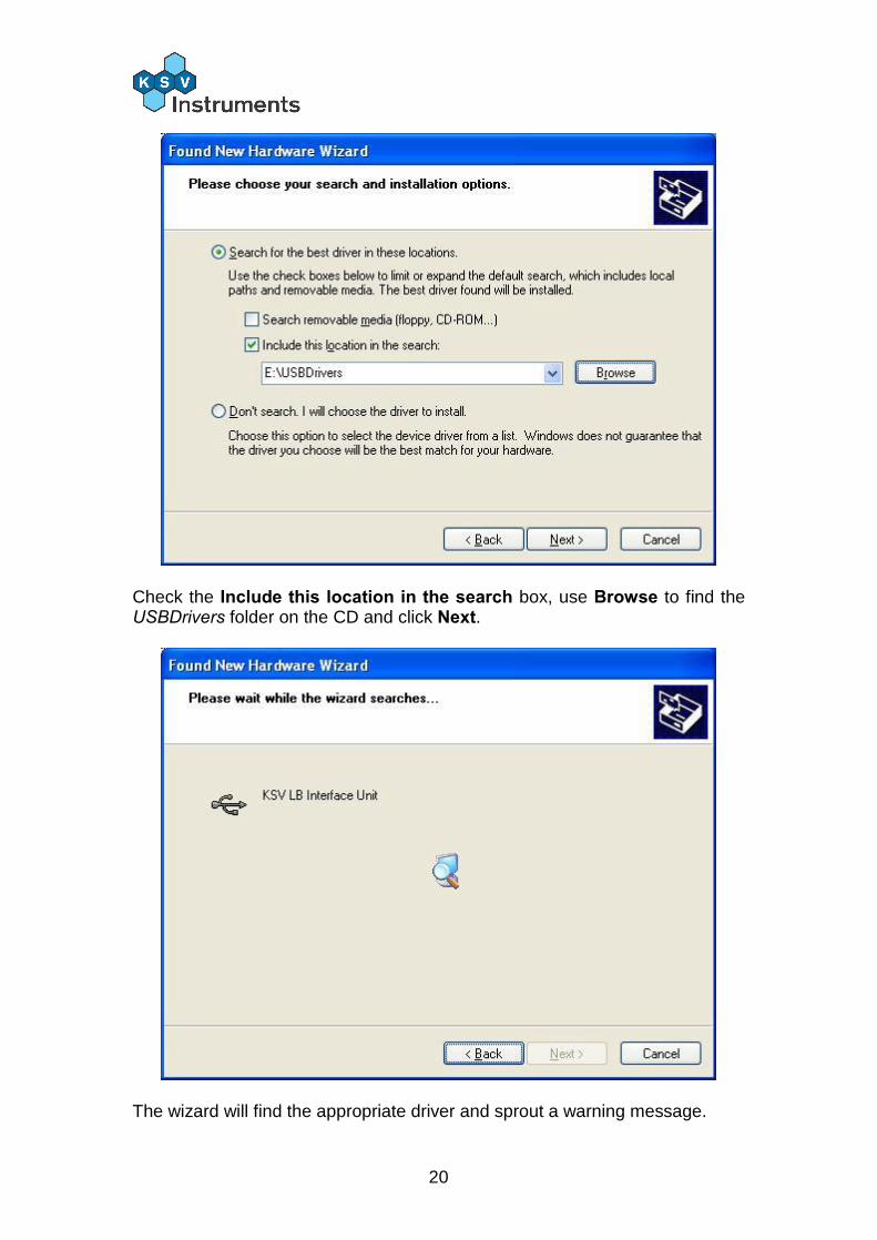
Check the Include this location in the search box, use Browse to find the USBDrivers folder on the CD and click Next.
The wizard will find the appropriate driver and sprout a warning message.
21
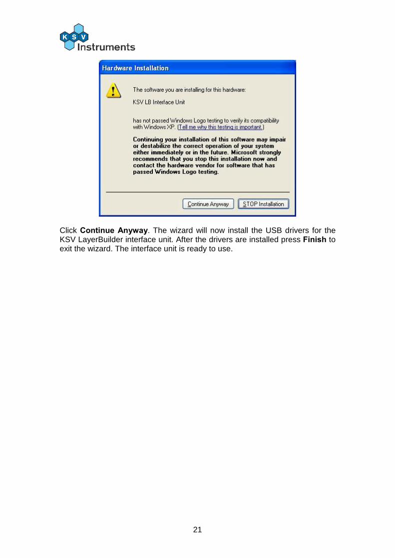
Click Continue Anyway. The wizard will now install the USB drivers for the KSV LayerBuilder interface unit. After the drivers are installed press Finish to exit the wizard. The interface unit is ready to use.
22
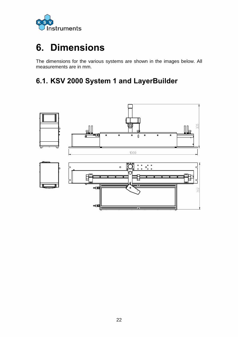
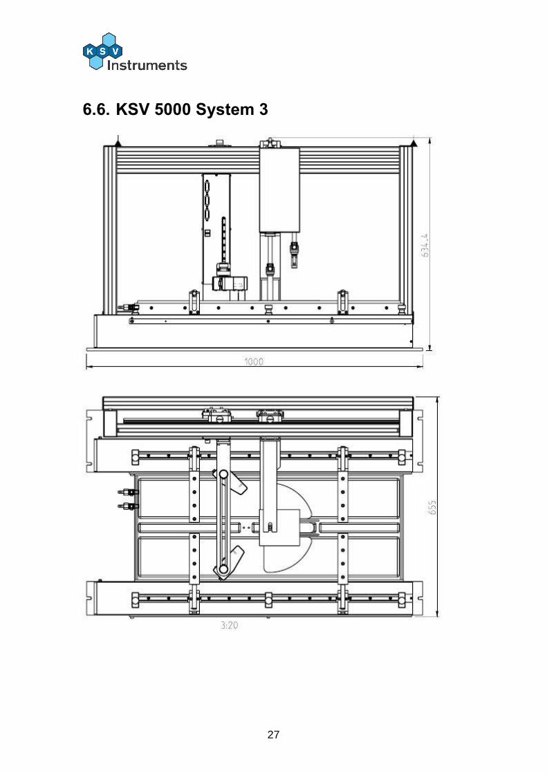
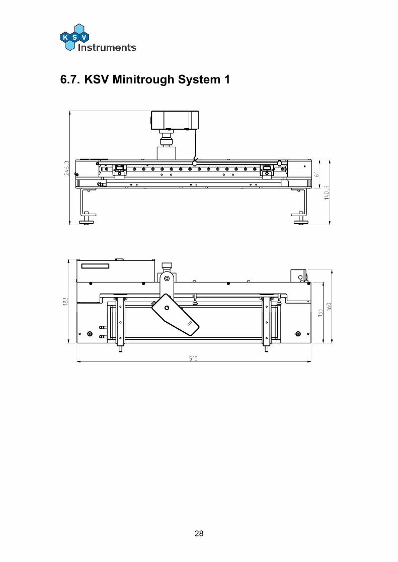
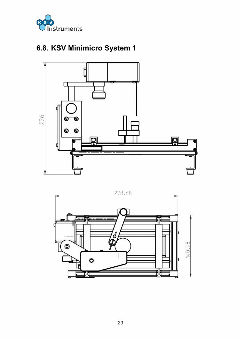
6. Dimensions The dimensions for the various systems are shown in the images below. All measurements are in mm.
6.1. KSV 2000 System 1 and LayerBuilder

23
6.2. KSV 2000 System 2
24
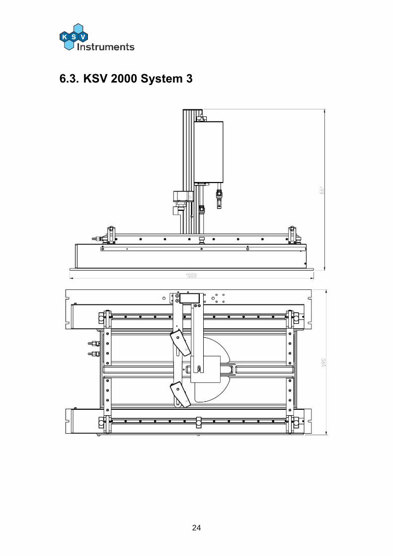
6.3. KSV 2000 System 3
25
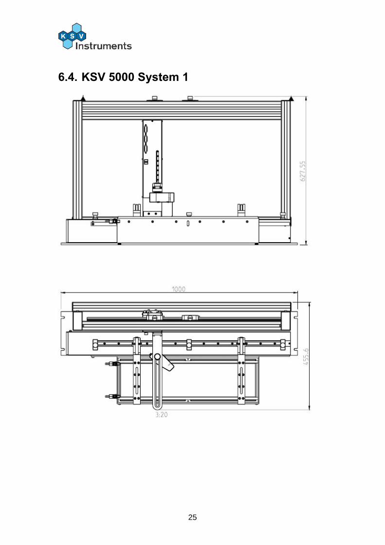
6.4. KSV 5000 System 1
26
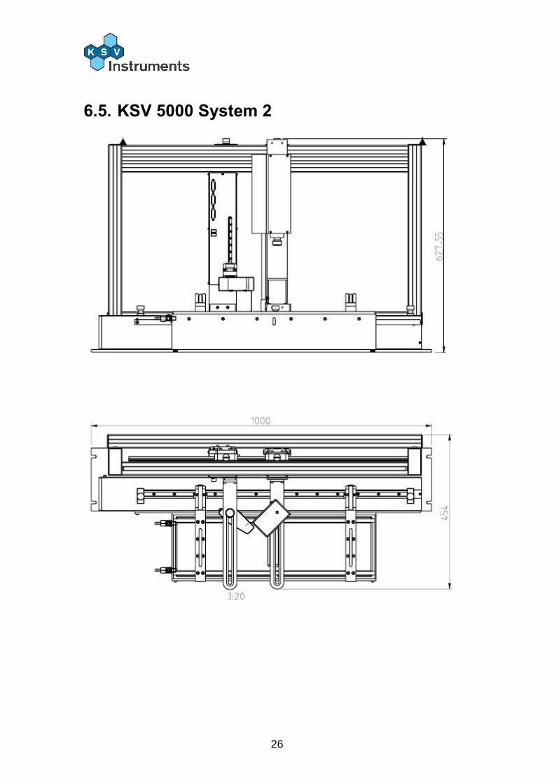
6.5. KSV 5000 System 2
27
6.6. KSV 5000 System 3
28
6.7. KSV Minitrough System 1
29
6.8. KSV Minimicro System 1

30
7. Contact Information If any problems arise please feel free to contact a local distributor or KSV Instruments directly. KSV Instruments can be contacted from this address:
KSV Instruments Ltd. Höyläämötie 7 FIN-00380 Helsinki Finland Tel. +358-(0)9-5497 3300 Fax +358-(0)9-5497 3333 E-mail [email protected] for sales and
[email protected] for service or technical questions http://www.ksvltd.com
Local distributors are listed at our website, www.ksvltd.com.