interactive drafting preface - serwis informacyjny - catia
TRANSCRIPT

Interactive Drafting
Preface
What's New
Getting Started
Basic Tasks
Advanced Tasks
Workbench Description
Customizing
Glossary
Index
© Dassault Systèmes 1994-99. All rights reserved.

PrefaceCATIA Version 5 Interactive Drafting is a new generation CATIA product thataddresses 2D design and drawing production requirements.
CATIA Interactive Drafting is a highly productive, intuitive drafting system that can beused in a standalone 2D CAD environment within a CATIA backbone system. It alsoexpands the CATIA Generative Drafting product with both integrated 2D interactivefunctionality and an advanced production environment for the dressup and annotationof drawings. This provides an easy and smooth evolution from 2D to 3D-based designmethodologies.
Complementing an existing CATIA Version 4 installation, Interactive Drafting benefitsfrom upward compatibilty with Version 4, making it possible to browse or complete inVersion 5 drawings started with Version 4.
The CATIA - Interactive Drafting User's Guide has been designed to show you how tocreate drawings from various complexities. There are several ways of creating adrawing and this documentation aims at illustrating the several stages of creation youmay encounter.

Using This DocumentationThis User's Guide is intended for a draftman who needs to become quickly familiar withCATIA-Interactive Drafting Version 5 product.Before reading it, the user should be familiar with basic CATIA Version 5 conceptssuch as document windows, standard and view toolbars.
To get the most out of this guide, we suggest that you start reading and performing thestep-by-step tutorial Getting Started and the Workbench Descriptionto find your way around the Drafting
To get the most out of this guide, we suggest you start reading and performing thestep-by-step tutorial Getting Started. This tutorial will show you how to create a basicdrawing from scratch.
The next sections deal with the handling of drawing, then the creation and modificationof various types of features you will need to obtain a complex drawing. This guide alsopresents other InteractiveDesign capabilities allowing you to design complex parts.You may also want to take a look at the sections describing the Interactive Draftingmenus and toolbars at the end of the guide.

Where to Find More InformationPrior to reading this book, we recommend that you read the CATIA- InfrastructureUser's Guide Version 5that describes generic capabilities common to all CATIA Version 5 products. It alsodescribes the general layout of CATIA V5, and interoperability between workbenches.Also read the CATIA V4 Integration documentation that presents interfaces withstandard exchange formatas and most of all with CATIA V4 data.
The CATIA - Generative Drafting User's Guide Version 5 and the CATIA- AssemblyDesign User's Guide Version 5 may prove useful too.
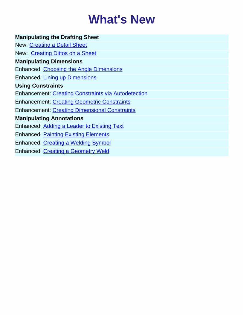
What's NewManipulating the Drafting SheetNew: Creating a Detail SheetNew: Creating Dittos on a SheetManipulating DimensionsEnhanced: Choosing the Angle DimensionsEnhanced: Lining up DimensionsUsing ConstraintsEnhancement: Creating Constraints via AutodetectionEnhancement: Creating Geometric ConstraintsEnhancement: Creating Dimensional ConstraintsManipulating AnnotationsEnhanced: Adding a Leader to Existing TextEnhanced: Painting Existing ElementsEnhanced: Creating a Welding SymbolEnhanced: Creating a Geometry Weld

Getting StartedBefore getting into the detailed instructions for using Interactive Drafting workbench, the followingtutorial aims at giving you a feel of what you can do with the product. It provides a step-by-stepscenario showing you how to use key functionalities.The main tasks described in this section are :
Tasks
This step-by-step scenario introduces the basic capabilities of Interactive Drafting. You just need tofollow the instructions as you progress along.Before discovering this scenario, you should be familiar with the basic commands common to allworkbenches. These are described in the Basics User's Guide.All together, the tasks should take about 30 minutes to complete.
The final drawing will look like this:


Entering the Interactive Drafting WorkbenchThis first task shows you how to enter the Drafting workbench and start a new drawing.
1. Select the File -> New commands (or click the New icon).
The New dialog box is displayed, allowing you choosing the type ofthe document you need. 2. Select Drawing in the List of Types field and click OK.
The New Drawing dialog box is displayed, allowing you choosing thetype of Standard, Format and orientation you need.
3. Select the ANSI standard and click the Landscape option. 4. Click OK.
The Drafting workbench is loaded and an empty Drawing sheet opens:

5. Make sure you customized the unit accordingly. For this:
a. Select the Tools -> Options command to display the Options dialog box.
b. Click General in the list of objects to the left of the Options dialog box.
c. Select the Units tab and set Length to Inch and then click OK.To visualize better your drawing, tile the windows horizontally from the menu bar.
The commands for creating and editing features are available in the workbench toolbar. Now to fully discoverthe Interactive Drafting workbench, let's perform the following tasks.


Creating a New ViewIn this task you will learn how to create a new view in the empty drawing you just opened using theDrafting Interactive workbench. Afterwards, you will draw geometry in this empty view.
1. Click the New View icon and click the Drawing sheet.
In the following tasks, you will learn how to draw geometry in the empty view displayedwhich is by default a front view.

Creating a RectangleThis task shows you how to define geometry in the newly created empty view which is bydefault, the front view. In this particular case, let's create a rectangle from coordinates 0,0 tocoordinates 3.5,2.5 (inches).
1. Click the Rectangle icon from the Geometrycreation toolbar (Profiles subtoolbar).
The Tools toolbar displays two value fields: horizontal value (H) and vertical value (V).
2. Enter the First Point coordinates. For example, H: 0in and V: 0in. 3. Press Enter.
4. Enter the Second Point coordinates. For example, H: 3.5in and V: 2.5in.5. Press Enter to end the rectangle creation.
The rectangle appears in the emptyview.
You can also move the cursor for directlypositioning the second point. The correspondingvalues similarly appear on the Tools toolbar.


Creating CornersThis task shows you how to create corners on an existing rectangle bymultiselecting points.
1. Multiselect therectangle endpoints.
2. Click the Corner
icon from theGeometry editiontoolbar (Relimitationssubtoolbar).The Tools toolbar displays with a Radius field:
3. Enter a radius value in the Tools toolbar. For example, Radius:0.25in.4. The four cornersare automaticallycreated with the sameradius value.
You can also select the Cornericon first and then click thegeometry for creating the cornersone after the others.


Creating LinesIn this task you will learn how to create a line.
1. Click the Line icon fromthe Geometry creation toolbar.
The Tools toolbar displays First Point value fields:
2. Enter the line First Point coordinates. For example, H: 1.625in and V:0in.
3. Press Enter.4. Drag the cursor to thedesired location for creating thesecond line point. For example,drag the line end point to thetop rectangle horizontal line.
In this particular case, autodetectionis used for creating the line. In otherwords, you want the line to beparrallel with one of the rectanglelines.

Translating LinesThis task shows you how to create additional lines from an existing one.
1. Select the line to be translated.
2. Click the Translate icon from the Geometryedition toolbar (Transformations subtoolbar).
The Translation Definition dialog box appears andthe Start Point value fields (H and V) display fromthe Tools toolbar.
3. The Duplicate mode option (TranslationDefinition dialog box) is activated, by default. Ifneeded, actvate this mode.
4. Enter the duplicated line Start Point coordinates in the Tools toolbar. For example, H:1.625in and 2.5in.
5. Press Enter.
6. Enter the duplicated line End Point coordinates in the Tools toolbar. For example, H:1.625in and 0in.
7. Press Enter.
8. Enter the line Length Value in theTranslation Definition dialog box. Forexample, 2.5in.
The Snap Mode is automatically deactivated.
9. Click OK to validate.
10. Once you are satisfied with youroperation, click inside the view.The second line is created.

Proceed in the same manner to create the third, fourth, fifth and sixth lines.The process describedabove is valid for any other line to be created with the Translation command in our context.
Select two lines at a time to perform your translation, it is time-saving.
Your final drawing will look like this:
You can also select the Translate icon first and then the geometry to be translated.

Creating CirclesThis task shows you how to create circles and circle centers using coordinates.
1. Select the Circle icon
from the Geometrycreation toolbar.
The Tools toolbardisplays circle valuefields.
2. Enter the Circle Center coordinates. For example, H: 0.75in ans H: 2in.
3. Press Enter.
4. Enter the circle radius. For example, R: 0.375in.
5. Press Enter.
6. Repeat the scenario tocreate the second circleusing the same values.

Now, let's create innercircles. For this:
7. Click again the Circle
icon .8. Select the existing circlecenter.
9. Enter the center circleradius.10. Press Enter.
11. Repeat the scenario tocreate the second innercircle.
This is what you obtain:
You can either select thegeometry to be translated first orthe Translation command.


Translating CirclesThis task shows you how to duplicate existing circles using translation.
1. Select the circles to be translated. Use the multiselection capability.
2. Click the Translate
icon from theGeometry editiontoolbar.
The TranslationDefinition dialog boxand the Start Pointvalue fields (Toolstoolbar) display.
3. Enter the StartPoint coordinates.For example, H: 0inand V: 0in.

4. Enter the EndPoint coordinates.For example, H:1.875 and V: 0in.5. Press Enter.
6. Enter the desiredLength value in theTranslation Definitiondialog box. Forexample, 1.875in.
The Snap mode isdeactivated.
7. Click OK toconfirm youroperation.
This is what youobtain:
You can either select the geometry to be translated first or the Translate icon .


Creating DimensionsThis task shows you how to add dimensions to the geometry you previouslycreated.
1. Clickthedimension
icon from theDimensioningtoolbar.
2. Clicka firstelementin theview.Forexample,therectangletop line.
3. Clickasecondelementin theview.Forexample,therectanglebottomline.
The dimension type is automatically defined according to theselected elements. In this case, you create a distance dimension.

4. Ifneeded,re-positionthedimensionto thedesiredlocation.
Now that you know how to quickly apply dimensions to 2Dgeometry, create as many as required.

Creating AnnotationsThis task shows you how to add annotations to existing 2D elements.
1. Click on an icon from theAnnotations toolbar.
For example, the Text icon .
2. Click an element you want toadd an annotation.
3. Enter the required text inthe Text Editor dialog box.
The text you just entered in the dialog box appears below the annotation in awysiwyg way.
4. If needed, drag the text to thedesired location.
5. Now that you know how toquickly apply annotations to 2Dgeometry, create as many asrequired.
The annotation will now remain associated to the selected 2D element. In otherwords, each time you move the 2D element, the associated annotation movesaccordingly.


Basic TasksThe basic tasks you will perform in the Interactive Drafting workbench are mainlythe creation and modification of two-dimensional elements and their relatedattributes on a predefined sheet.
This section will explain and illustrate how to create various kinds of features toobtain a complete CATDrawing document. The table below lists the informationyou will find.
Theme

Manipulating the Drafting SheetThe Interactive Drafting workbench provides a simple method to manipulate a sheet.Now, you are going to define and modify the sheet and its background through thecreation of a frame title block.
Tasks

Defining a SheetThis task will show you how to define a sheet.
1. Click or select the File -> Newcommands2. Select the Drawing workbench, andclick OK.
3. Select the Landscape option from theNew Drawing dialog box.4. Click OK.
You can modify at any time the sheetorientation and/or scale. For this, you selectthe File->Page Setup items from the toolbar.
The sheet size depends on the standardselected. For example, if you choose the ISOstandard, the sheet will automatically beassigned the A0 format.

To add a new sheet, click the New Sheet icon . The new sheetautomatically appears as follow :
Once you have created more than one sheet, to activate one of the sheets,select this sheet from the dialog window.

Modifying the SheetThis task will show you how to modify the sheet orientation.
Create a sheet using the Landscape orientation in the New Drawing dialog box.
1. Select the File->PageSetup items from themenu bar.2. Click OK.
Using this dialog and the Page Setup dialog box, you can also modify the sheetscale which is set to 1, by default.


Deleting a SheetThis task will show you how to delete a sheet. When a CatDrawing is open, asheet is necessarily displayed. This is why you can only delete a sheet otherthan sheet number one.You created more than one sheet.
1. Select the sheet fromthe specification tree.For example, Sheet 2.2. Right-click theselected sheet anddisplay the contextualmenu.2. Select the Deleteoption from thecontextual menu.
Sheet 2 is deleted.


Creating a Frame Title BlockThis task shows you how to create a background sheet and insert a frame and atitle block.Open a CATDrawing document.
1. Select the Edit->Background items from the menu bar.
2. Click the Frame Creation icon.
The Insert Frame and Title Block dialog box is displayed.

3. Click OK.The Insert Frame and Title Block are as follows:


Creating a Detail SheetThis task will quickly show you how to create a detail sheet. In other words, youare going to create some kind of a intermediary catalog that you will use forpositioning dittos on a drawing sheet afterwards.
1. Click the NewDetail Sheet icon
from theSheets toolbar.
The newly createddetail sheetautomaticallydisplays.
For more information on how to customize sheet background colorssee CATIA.Generative Drafting user's guide.

Creating Dittos on a SheetThis task shows you how to create dittos from a detail previously created on adetail sheet.Create a detail sheet and enter the drawing sheet in which you want to insertdittos.
1. Click theInstantiate Detail
icon .
2. Go to the detailsheet (sheet 2)and select theditto.
You can select the ditto from the design tree. You can also select aditto that already exists on the drawing sheet.
The drawingsheetautomaticallydisplays (sheet1).
4. Click toposition the ditto.
5. If needed,modify the newlypositioned dittoscale and/orangle.

You can modify the ditto via manipulators. You can also modify agroup of objects including a ditto.
For positioning several dittos on the sheet, double click the Instantiate
Detail icon .

Creating ViewsThe Interactive Drafting workbench provides a simple method to create views.
This task will show you how to create views. If the sheet is active, the first viewyou create is by default a front view.
1. Click the New View icon .
2. Click the Drawing window.
A blue axis displays in a red frame. Thefront view created displays in thespecification tree.
3. Click again the New View icon for creating more views.The views created are projection views as they are linked to the frontview.
You can create:Top viewsBottom viewsLeft viewsRight views
from an active front view.
If you need to switch to the Third angle projection method, specify it via theSheet Properties option.

4. Activate a projection view by double-clicking the view.
5. Click the New View icon for creating the rear view.
The following table shows the possibilities of view creation according to theactive view type.
Active View Resulting Projection Views (linked tothe active view)
Front view
Bottom viewTop viewRight viewLeft view

Left viewRight view
Rear views
or
Auxiliary views
Rear view Auxiliary view

Creating 2D GeometryThe Interactive Drafting workbench provides a simple method for creating andediting two-dimensional geometry.The tools it offers enable you to create and edit geometry, dimension and createrelations between 2D elements.
Note also that the Interactive workbench provides Autodetection an easy-to-usetool designed to make all your geometry creation as simple as possible.Before creating 2D geometry, you can double-click the icon and then create asmany elements as desired.
Tasks


Helpful Tools
This task shows how CATIA can assist you when creating two-dimensional geometry.Multiselection can be also very useful.
The Tools toolbar provides four options:GridSnap to PointVisualize/Create constraints*Differentiating between two-dimensional elements and generated elements from3DValue FieldsA Few Words About Multiselection
Grid
The grid will help you draw geometry in some circumstances. For example, the grid willmake it easier to draw profiles requiring parallel lines. For more information aboutdefining a grid, see Setting a Grid.
Snap to Point
If activated, this option makes your geometry begin or end on the points of the grid. Asyou are creating two-dimensional geometry the application forces points to theintersection points of the grid. Note that this option is also available in the Tools ->Options -> Drafting ->General tab. For more information, see Setting a Grid.
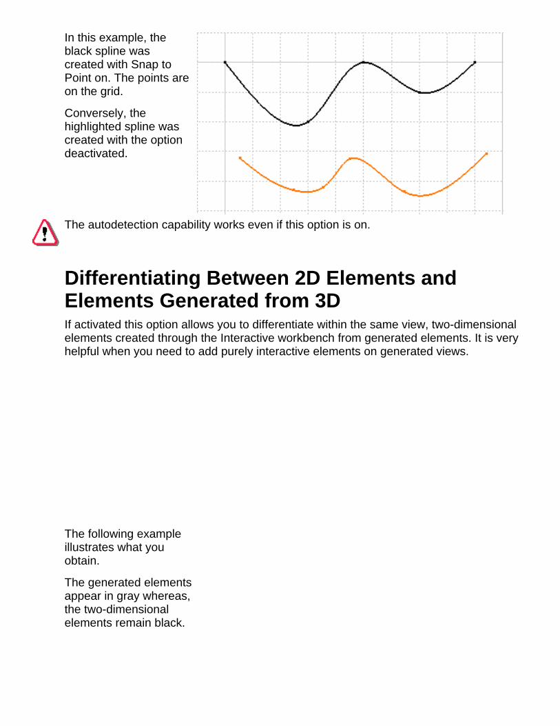
In this example, theblack spline wascreated with Snap toPoint on. The points areon the grid.
Conversely, thehighlighted spline wascreated with the optiondeactivated.
The autodetection capability works even if this option is on.
Differentiating Between 2D Elements andElements Generated from 3DIf activated this option allows you to differentiate within the same view, two-dimensionalelements created through the Interactive workbench from generated elements. It is veryhelpful when you need to add purely interactive elements on generated views.
The following exampleillustrates what youobtain.
The generated elementsappear in gray whereas,the two-dimensionalelements remain black.

This command is available only with the Generative Drafting license.
Value Fields (Tools Toolbar)The values of the elements you sketch appear in the Tools toolbar as you move thecursor. In other words, as you are moving the cursor, the Horizontal (H), Vertical (V)Length (L) and Angle (A) fields display the coordinates corresponding to the cursorposition.
You can also use these fields for entering the values of your choice. In the followingscenario, you are going to sketch a line by entering values in the appropriate fields.
1.Click the line icon .The Tools toolbar displays frout value fields.

As you are moving the cursor, the Horizontal (H), Vertical (V) Lenght (L) andAngle (A) fields display the coordinates corresponding to the cursor'sposition.
1. Click the
Line iconfrom theGeometrycreationtoolbar.The Tools toolbar displays information on value fields.
2. Enter the coordinates of the First Point.
3. Enter the coordinates of the Second Point.
OR
4. Enter the length (L) of the line.
5. Enter the value of the angle (A) between the line to be created and thehorizontal axis.
The line is created.Depending on the number of fields available and the way you customized your toolbars,some fields may be truncated.What you need to do is just undock the Tools toolbars.
A Few Words About MultiselectionThis task shows you that creating several corners is possible just by multiselectingpoints.

1. Multiselectthe rectangleendpoints bypressing theCtrl key andthe cursor.2.Click theCorner icon
from theGeometryedition toolbar.
.3. Enter aradius value inthe Radiusfield thatappears in theTools toolbar.4. The fourcorners arecreated at thesame time withthe sameradius value.

PointsThis task shows you how to quickly create points by clicking:
1. Click the Point icon from the Geometrycreation toolbar.
2. Click once for each point to be created.A point is created where you clicked.
The logical constraints detected during thecreation of a point are stored in memory.

Points Using CoordinatesThis task shows you how to create points by specifying coordinates.
1. Click the Point By Using Coordinates icon
from the Points toolbar.
The Point Definition dialog box is displayed.
2. Enter the point coordinates (h and v) fromthe Point Definition dialog box.You can use a cartesian or polar definition.
3. Click OK.The point is created.

Equidistant PointsThis task shows how to create a set of equidistant points on an arc. In otherwords, you can create points on the support of your choice. You only need toselect the origin point, and specify the spacing and the number of points youwish.
Create an arc.
1. Click the Equidistant Points
icon from the Points toolbar.
2. Select the starting point of thearc on which you wish to createfive equidistant points.3. Select the arc endpoint on the left todefine the arc.
The Equidistant Points Definition dialogbox is displayed.Ten equidistant New Points is the defaultvalue.The default spacing is 10mm.

4. Click the Reverse Direction button toreverse the creation direction. The points willthen be created on the arc.
5. Enter the distance you need betweeneach point. For example, 20mm.
6. Enter five as the desired number ofpoints.
7. Click OK.
The points are created and distributed along the arc. You can edit themindividually.
Note that if the support is edited, the points are not affected by modifications.
The symbol used for points in the geometry area can be customized using theEdit -> Properties command.

LinesThis task shows how to create a line between two points.
1. Click the Line icon from theGeometry creation toolbar.
2. Click to create the first point, andpoint elsewhere.A rubberbanding line follows thecursor, showing the shape of the linewhich will be created.
3. Click to create the second point.The logical constraints detected duringthe creation of a line are stored inmemory.


CirclesThis task shows how to create basic circles with no precision.
1. Click the Circle icon from theGeometry creation toolbar.
2. Click the intended center of the circle.
3. Move the cursor to see the circle beingcreated.A rubberbanding circle follows the cursor asyou drag it.

4. Click once you are satisfied with the sizeof the circle.
The logical constraints detected during thecreation of a circle are stored in memory.

Three Point Circles
This task shows how to create circles by indicating three points.
1. Click the circle icon fromthe Geometry creation toolbar(Circles and Ellipse subtoolbar).
2. Click two points.The application previews a circle.
3. Click the third point.
The circle is created.


Circles Using CoordinatesThis task shows how to create circles specifying center point coordinates.
By default, centers are created but if you do not need them you can specify thisin the Options dialog box. For more information, please refer to CustomizingGeometry Creation
1. Click the Circle Using
Coordinates icon from theGeometry creation toolbar(Circles and Ellipse subtoolbar). The Circle Definition dialog box isdisplayed.2. Enter the coordinates of thecenter point.
3. Enter the desired circle radiusvalue.
4. Click OK.The circle and its center point arecreated.

You can also use the Polar taboptions for creating a circle. Inother words, you will define thecircle using the radius and angleof the center point.

ArcsThis task shows how to create an arc from a center point.
1. Click the arc icon from theGeometry creation toolbar (Circles andEllipse subtoolbar).
2. Click to the intended center of thearc and drag the cursor.A circle appears.
3. Click when you are satisfied with theradius of your circle.This sets the first limit of the arc.
4. Now, moving the cursor clockwise andclicking, you would obtain this arc:
5. Moving the cursorcounterclockwise and clicking,you would obtain this arc:


Three Point Arcs This task shows how to create an arc using three reference points to define the
required size and angle
1. Click the Three
Point Arc icon from theGeometry creationtoolbar (Circlesand Ellipsesubtoolbar).2. Point and clickto where you wishthe arc to begin.This point is thefirst point throughwhich the arc willpass.
3. Click to thesecond point ofthe arc.An arc appears.
4. Point elsewhereand click again tocreate the lastpoint of the arc.
The logicalconstraintsdetected duringthe creation of anarc are storedmemory.


EllipsesThere is a simple way for creating an ellipse: this task shows how to do so. Anellipse has two axes. The midpoint of each axis is the center point of theellipse.
1. Click the Ellipse icon fromthe Geometry creation toolbar(Circles and Ellipse subtoolbar).
2. Click to create the first point.
3. Click to create the secondpoint.
The first major semi-axis of theellipse is created.
4. Click to create the third point.The second semi-axis is createdand the ellipse is displayed.


ProfilesThis task shows how to create a profile using the different options of the profilecommand. You can create open or closed profiles. Profiles may be composedof lines, arcs or even curves.
1. Click the Profile
icon from theGeometry creationtoolbar.
The Tools toolbardisplays with Lines,Tangent Arcs andThree Point Arcscommands.The Line command
is activated bydefault.
2. Click two pointsto create a line.A rubberbandingline follows thecursor, showing thenext line which willbe created.

3. Click the Tangent
arc icon that isnow available asyou have created aline.
4. Drag the cursorand click where youwish to end thetangent arc.The tangencysymbol isdisplayed.
5. Now, click theThree Point Arc
icon .6. Click two pointsas indicated.
An arc is created aswell as the threepoints you clicked.
7. Click the Line icon anddrag the cursor vertically tocreate the line as shown.
An arc is created as well as thethree points you clicked.
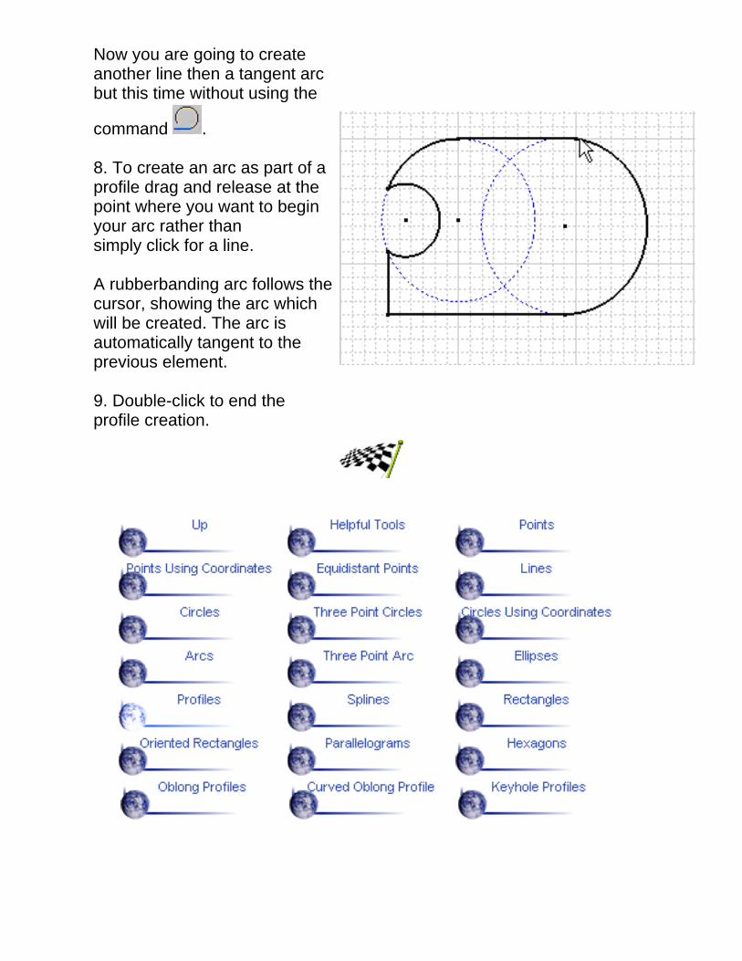
Now you are going to createanother line then a tangent arcbut this time without using the
command .
8. To create an arc as part of aprofile drag and release at thepoint where you want to beginyour arc rather thansimply click for a line.
A rubberbanding arc follows thecursor, showing the arc whichwill be created. The arc isautomatically tangent to theprevious element.
9. Double-click to end theprofile creation.

SplinesThis task shows how to create a curve from scratch.
1. Click the Spline icon fromthe Geometry creation toolbar.
2. Click to indicate two pointsthrough which the curve passes.
3. Click as many times asneeded to create the wholecurve.4. Double-click to end the curve.
Clicking the Select icon ends the curve too.


Rectangles
This task shows you how to create rectangles.
1. Click the Rectangle icon
from the Geometrycreation toolbar (Profilessubtoolbar).
2. Point to the intended firstcorner of the rectangle.
3. Drag to see therectangle beingcreated.A rubberbandingrectangle follows thecursor as you drag it.
4. Click to create therectangle.


Oriented RectanglesThis task shows how to create a rectangle oriented in the direction of yourchoice.
1. Click the Oriented Rectangle
icon from the Geometrycreation toolbar (Profilessubtoolbar).
2. Click two points to create thefirst side of the rectangle.
3. Drag to see therectangle being created.
4. Click to create the rectangle.The logical constraints detectedduring the creation of therectangle are stored in memory.


ParallelogramsThis task shows how to create a parallelogram.
1. Click the Parallelogram
icon from the Geometrycreation toolbar (Profilessubtoolbar).
If you activate the and options from the Tools toobar. Theconstraints are shown and created. Refer to Helpful Tools and CustomizingConstraints.
2. Click two points to createthe first side of theparallelogram.
3. Drag to see theparallelogram being created.
A rubberbandingparallelogram follows thecursor as you drag it.4. Click to create theparallelogram.
The logical constraintsdetected during the creationof a parallelogram arememorized.


HexagonsThis task shows how to create an hexagon.
1. Click the Hexagon
icon from theGeometry creationtoolbar (Profilessubtoolbar).
2. Click a point to definethe first point of thehexagon.
3. Drag the cursor todefine a radius value.CATIA previews thehexagon to be created.
4. You can move thecursor clockwise orcounter-clockwise toposition the hexagon.

5. Click a second pointwhen you are satisfiedwith the radius valueand the orientation ofthe hexagon.
The hexagon is created.

Oblong ProfilesThis task shows how to create an oblong profile. The steps required for creatingthis type of profile are similar to creating an ellipse.
1. Click the Oblong
Profile icon from theGeometry creationtoolbar (Profilessubtoolbar).
2. Click to create thefirst point and drag thecursor.
3. Click to create thesecond point.
The first semi-axis of theprofile is created.
4. Drag the cursor andclick to create the thirdpoint.
The second semi-axis iscreated and the oblongprofile is displayed.


Curved Oblong ProfileThis task shows how to create a curved oblong profile. A construction arcassists you in creating this element.
1. Click the Curved
Oblong Profile icon from the Geometrycreation toolbar (Profilessubtoolbar).
2. Click two points todefine the radius of theconstruction arc.
The second point youclicked is the firstendpoint of theconstruction arc.
3. Move the mousecounterclockwise andclick to define thesecond construction arcendpoint.
The profile shape lookslike this:
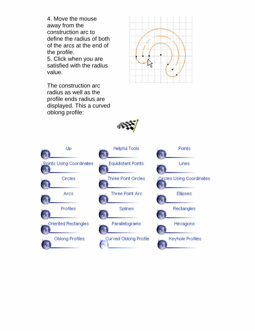
4. Move the mouseaway from theconstruction arc todefine the radius of bothof the arcs at the end ofthe profile.5. Click when you aresatisfied with the radiusvalue.
The construction arcradius as well as theprofile ends radius aredisplayed. This a curvedoblong profile:

Keyhole ProfilesThis task shows how to create a keyhole profile.
1. Click the Keyhole
Profile icon from theGeometry creationtoolbar (Profilessubtoolbar).
2. Click one point.
This point is thecenterpoint of the arc.
3. Click another point.
4. Drag to define the width of the lower part ofthe profile and clickwhen satisfied.
5. Drag the cursor todefine the circle radiusof the upper part of theprofile.
6. Click when you aresatisfied with the radiusvalue.

This is a keyhole profile:

Editing 2D ElementsThe Interactive Drafting workbench provides a simple method to edit 2DGeometry elements. Editing 2D elements means modifying their coordinates butalso modifying their shapes using commands such as edit, relimit and break.
Tasks

Modifying Element CoordinatesModifying your sketch coordinates will impact the feature defined on this sketch:CATIA maintains associativity.
The instructions described below are valid for editing all elements. Notehowever, that profiles are not considered as entities when it comes to editingthem. To edit a profile, you will need to edit the sub-elements composing it.This task shows how to edit the line coordinates.
1. Double-click the line you wish to edit.
The corresponding dialog box appears indicating the line coordinates.2. Enter newcoordinatesfor changingyour endpoints.3. Check theConstructionElementoption if youwish tochange theline type.4. Press OK.
Remember that the Edit -> Properties command lets you access and even edittwo dimensional elements properties.Multiselection is not allowed before editing 2D elements.

Creating and Editing CornersThe corner is an arc tangent to two curves.
You can create rounded corners between consecutive lines, arcs, circles and anytypes of curves using the corner command which displays three trim options. Note thateven if the curves are not consecutive, but simply intersect, the corner will be created.
By default, centers are created but if you do not need them you can specify this in theOptions dialog box. For more information, please refer to Customizing GeometryCreation
Corners with Both ElementsTrimmed This task shows how to create a corner between two lines and trim these lines.
1. Click the Corner icon .
The possible corner options are displayed.The Trim all command is activated bydefault.
2. Keep this option and select the first line.
The selected line is highlighted.
3. Select the second line.
The second line is also highlighted, and thetwo lines are joined by the rounded cornerwhich moves as you move the mouse. Thislets you vary the dimensions of the corner.

4. Click when you are satisfied with thecorner dimensions.
Both lines are trimmed to the points oftangency with the corner.
An Alternative Method
To create a corner between two consecutive lines created using the , ,
or the commands, you can apply the method described above, but youcan also use the alternative method illustrated below, which is even more simple.
1. Click the Corner icon andfor example, leave the defaulttrim option.
2. Select the point intersectingthe lines.
The selected point is highlightedand the two lines are joined bythe rounded corner which movesas you move the mouse.

3. Click when you are satisfiedwith the dimensions of thecorner.
Both lines are trimmed to thepoints of tangency with the arc.
To edit a corner, you need toreconsider the center point location.This task will show you how to do so.
1. Double-click the corner to bemodified.2. Select circle->definition fromthe contextual menu
The Circle Definition dialog boxis displayed.
3. Enter a new radius value.4. Click OK to confirm youroperation
Repeat the above scenario to editchamfers

Creating ChamfersYou can create beveled corners between any types of curves (lines, splines, arcs andso forth.) using the Chamfer commandwhich displays three trim options. Note that if the curves are not consecutive, butsimply intersect,the chamfer will be created and the intersecting curves will be trimmed.
Chamfers with Both Elements TrimmedThis task shows how to create a chamfer between two lines while trimming them.
1. Click the Chamfer icon .The possible chamfer options are displayed. The Trim all option is thedefault option.
2. Select the line.The selected line is highlighted.
3. Select the second line.The second line is also highlighted, and thetwo elements are connected by a linerepresenting the chamfer which moves as youmove the mouse. This lets you vary thedimensions of the chamfer.
4. Click when you are satisfied with thedimensions of the chamfer.
The chamfer is created.

An Alternative MethodTo create a chamfer between two consecutive lines created with the Profile icon
, or the command, you can also use the alternative method illustrated below:
1. Click the Chamfer icon and for example,leave the default trim option.
2. Select the intersection point as shown.
The selected point is highlighted and the two linesare joined by the chamfer which moves as youmove the mouse.
3. Click when you are satisfied with thedimensions of the chamfer.
Both lines are trimmed.

Trimming ElementsThis task shows how to relimit a line. The trim command lets you relimit lines orcircles, or points, lines or circles.
1. Click the Trim icon from theGeometry edition toolbar (Relimitationssubtoolbar).
The Tools toolbar displays the Trim Alloption (default command).
2. Select the first line.
The selected element is highlighted.
3. Select the second point, line or circle.
The second element is highlighted too, and both elements are trimmed.
If you select the same first element, it will be trimmed at the location of thesecond selection.
The location of the trim depends on the location of the mouse:
4. Click where you are satisfied with the trimmimg of the two elements:First example Second example

Third example Fourth example
Now, If you prefer to trim just one element, this task shows how to do so. In thisexample, we use a line. We could also use a circle.
5. Click the Trim icon from theGeometry edition toolbar (Relimitationssubtoolbar).
6. Click the Trim one element icon from the displayed Tools toolbar.
7. Select the first line.
The selected line or circle is highlighted.
8. Select the second line.
The first line selected is trimmed.
If you select the same first element, it willbe trimmed at the location of the secondselection.

The location of the trimmimg dependson the location of the mouse.

Breaking ElementsThe purpose of this task is to show how to break a line using a point on the lineand then a point that does not belong to the line. The Break command lets youbreak any types of curves. The elements used for breaking curves can be anySketcher element.
1. Click the Break icon from theGeometry edition toolbar(Relimitations subtoolbar).2. Select the line to be broken.3. Select the breaking element, that isa point.
The selected element is broken at the selection point. The line is now composedof two movable segments.
1. Click the Break icon fromthe Geometry edition toolbar(Relimitations subtoolbar).
2. Select the breaking point.3. Select the line to be broken.

The application projects the point onto the line and createsanother point.
The line is broken at the projected point. The line is nowcomposed of two segments that can be moved.
Using the Break icon, you can also isolate points:if you select a point that limits and is common two two elements, thepoint will be duplicated.if you select a coincident point, this point becomes independent (is nomore assigned a coincidence constraint).

Applying Transformations to 2DGeometry
The Interactive Drafting workbench provides a simple method to createtransformation features on 2D Geometry. Transformation features are obtainedby applying commands on existing elements.
Tasks

Creating SymmetryYou can use the symmetry command whenever you wish to copy alreadyexisting 2D elements. You can repeat them using a line, construction line or anaxis.This task shows how to duplicate a circle.
Create a circle and an axis.
1. Select the circle to be duplicated bysymmetry.
The Symmetry icon is now available.
2. Click the Symmetry icon from theGeometry edition toolbar.
3. Select the axis you have previously created.
The selected circle is duplicated and theapplication creates a symmetry constraint.


TranslatingThis task will show you how to create copies of eements using translation in theduplicate mode. Multi-selection is not available.You may either perform a simple translation (by moving elements) or createseveral copies of two-dimensional elements.
Make sure the view is active.
1. Click the Translate icon from theGeometry edition toolbar(Transformations subtoolbar).
The Translation Definition dialog boxdiplays and will remain displayedthroughout the operation.
2. Enter the number of Instances youneed (Instances).The duplicate mode is activated bydefault.
3. Select the element(s) to betranslated.
You may select one 2D element to betranslated or mutiselect the entiretwo-dimensional geometry drawn onyour sheet. See A Few Words AboutMultiselection.

4. Click the translation vector startpoint on the sheet or select an existingone.
5. In the Translation Definition dialogbox, enter a precise value for thetranslation length. For example, 10mm.
6. Use the Autodetection to maintainhorizontality.
7. Click OK in the Translation Definitiondialog box to end the translation.
The last translation is alwayshighlighted. Thus, you may restart fromthe latter if you need more copies.

The Undo command is available from the toolbar, while you are translatingelements.
When the Duplicate mode is activated, only 2D geometry is translated,dimensions are not.When the Duplicate mode is deactivated, both 2D geometry and itsassociated dimensions are translated. Therefore associativity ismaintained.

Rotating
This task will show you how to rotate elements. In this scenario, the geometry is simply moved. Butnote that, you can also duplicate elements with the Rotating command.
Make sure the view is active.
1. Click the Rotate icon from the Geometry editiontoolbar (Transformationssubtoolbar).
The Rotation Definitiondialog box diplays and willremain displayed all alongyour rotation.
2. Deactivate the Duplicatemode.
3. Enter the number ofcopies you need (Instances).
4. Select the geometry to berotated. Here, multiselect theentire profile.
5. Click the rotation centerpoint position or enter aprecise value in the fieldsdisplayed.
6. Click a point for definingthe reference line that will beused for computing theangle.
7. In the Rotation Definition dialog box, enter a precise value for the rotation angle.The step mode computes from 15 degrees to 15. But be the step mode activated or not, you mayenter the value of your choice (for example, 92 degrees).

7. Click OK to end therotation.
When the Duplicate mode is activated, only 2D geometry is rotated, dimensions are not.When the Duplicate mode is deactivated, 2D geometry and the associated dimensions arerotated. Therefore, associativity is maintained.

ScalingThis task will show you how to scale an entire profile. In other words, you aregoing to resize a profile to the dimension you specify.
1. Click the Scale
icon from theGeometry editiontoolbar(Transformationssubtoolbar).
The Scale Defintion dialog boxdiplays and will remaindisplayed all along youroperation.
2. Select theelement(s) to bescaled.
Note that you can first selecteither the geometry or thescaling icon. If you select theScale icon first, multiselectioncapability is available.
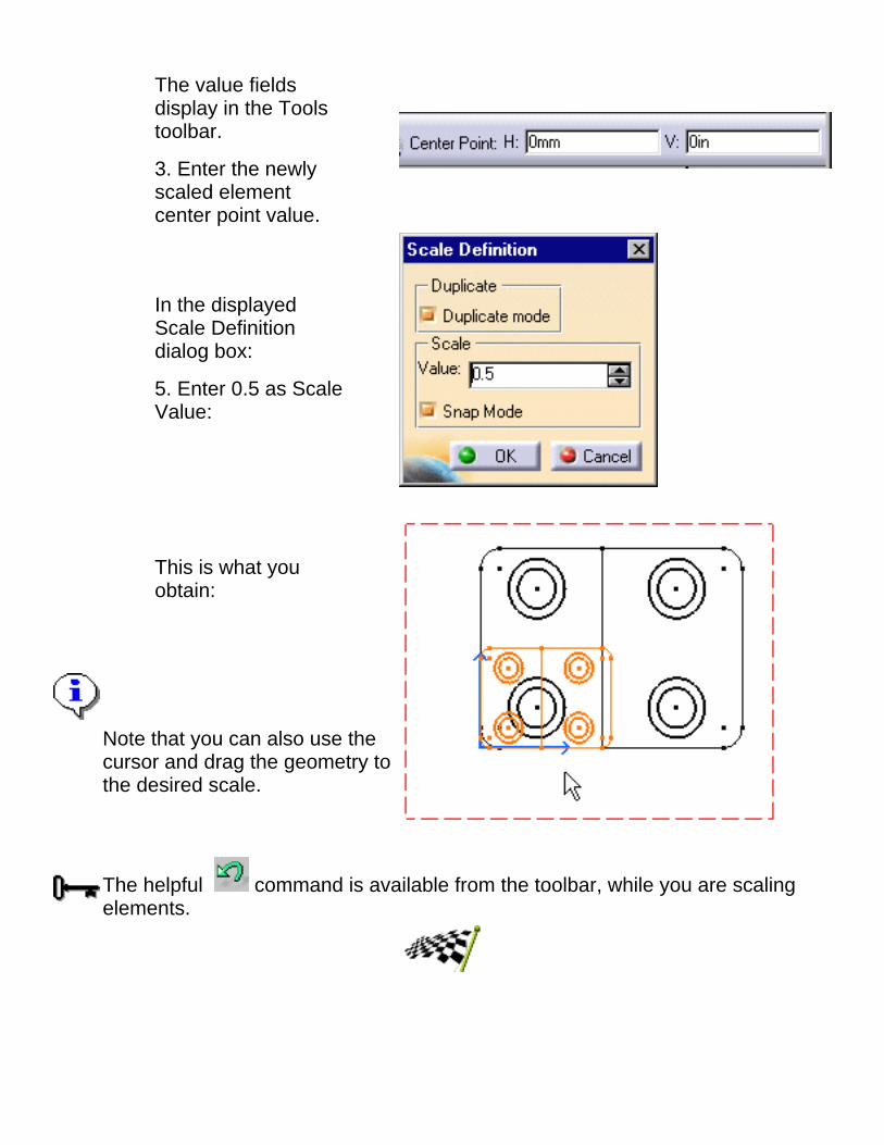
The value fieldsdisplay in the Toolstoolbar.
3. Enter the newlyscaled elementcenter point value.
In the displayedScale Definitiondialog box:
5. Enter 0.5 as ScaleValue:
This is what youobtain:
Note that you can also use thecursor and drag the geometry tothe desired scale.
The helpful command is available from the toolbar, while you are scalingelements.


Manipulating DimensionsThe Interactive Drafting workbench provides a simple method to manipulate alltypes of dimensions using the following toolbar:
The Interactive Drafting workbench allows you creating and/or modifying giventypes of dimensions. This is described in detrail in chapter called Before youBegin.
Tasks


Before you Begin
Creating DimensionsCATIA Interactive Drafting version 5 provides a unique and powerful commandto create the following types of dimensions:Dimensions created onone element
Length dimensionsDiameter dimensionsRadius dimensions
Dimensions created on twoelements
Distance dimensionsAngle dimensions
The dimension type will depend on the selected elements as explainedhereafter:
Modifying the Dimension AttributesCATIA Interactive Drafting version 5 provides a unique and powerful commandto modify the following attributes at any time before you click to validate thedimension creation:

Modify while creating
TypeMeasure direction
Modify while or just aftercreating
Value positionOverrun/blankingInserted prefixTool bar

Creating DimensionsThis task will quickly show you how to create a dimension. When creating adimension on 2D elements (except points), CATIA lets you preview thedimensions to be created.Open the Brackets_views.CATDrawing document from the\online\samples\IntDrafting directory.
1. Click from theDimensioning toolbar.
2. Click a first element in theview.
3. If needed, click a secondelement in the view.The dimension type isautomatically defined accordingto the selected elements.At this step, two icons allow positioning the dimension line eitheraccording to a reference element or to a reference view.
4. Click either the Reference Element icon or the View Reference
icon from the tools toolbar.
5. Click the View Reference icon.
6. Click the drawing window forvalidating the dimension creation.

Note that if you right-click the dimension before creation, a contextual menu letsyou modify the dimension type and its value orientation as well as add funnels.
Once the dimension is created, if you right-click you access the Propertiesoptions. Dimensions properties are detailed in Chapter Displaying and EditingDimensions Properties.

Choosing Angle DimensionThis task will quickly show you how to create an angle dimension and perform inthe meantime three kinds of modifications: new angle sector, new angle sectorlocation or turning an angle sector into a supplementary sector.Create two lines and apply an angle dimension to them (by selecting two linetype elements).
1. Click fromthe Dimensioningtoolbar.2. Select thedimension line.
3. With themouse, drag theangle dimensionto the desiredquadrant (orsector).
Lastly, you may turn the angle sector into a supplementary sector.
4. Press theConstrol key andselect thedimension line.

You may move the dimension to a new sector by using the contextualmenu:Right-click theangle dimensionand select therequired Anglesector from thecontextual menu.For example,Sector 3.

Modifying the Dimension TypeThis task will quickly show you how to modify the type as you create thedimension. On other words, you modify the dimension attributes. In this particularexample, we will apply a Radius Center dimension type to a hole.Open the Brackets_views.CATDrawing document from the\online\samples\IntDrafting directory. Create a diameter dimension.
1. Click fromthe Dimensioningtoolbar and a firstelement in the view.
2. If needed, click asecond element inthe view.The dimension type is automatically defined according to the selectedelements.3. Right-click the dimension.
4. Select the required type from the displayed menu. For example,Radius Center.
The diameterdimension isautomaticallysnapped to a radiusdimension.

5. Click the drawingwindow forvalidating thedimension creationand if needed,modify thedimension location.
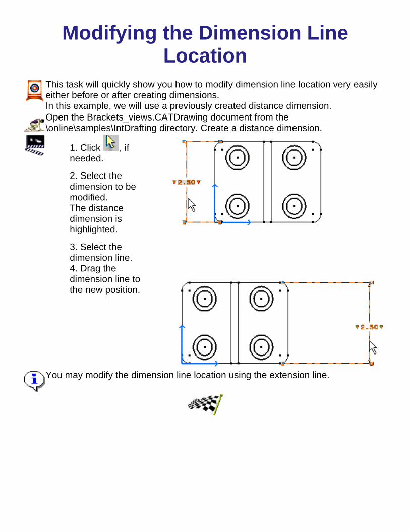
Modifying the Dimension LineLocation
This task will quickly show you how to modify dimension line location very easilyeither before or after creating dimensions.In this example, we will use a previously created distance dimension.Open the Brackets_views.CATDrawing document from the\online\samples\IntDrafting directory. Create a distance dimension.
1. Click , ifneeded.
2. Select thedimension to bemodified.The distancedimension ishighlighted.
3. Select thedimension line.
4. Drag thedimension line tothe new position.
You may modify the dimension line location using the extension line.


Modifying Dimension Value TextPosition
This task will quickly show you how to modify dimensions value text. In thisexample, we will use a previously created distance dimension.Open the Brackets_views.CATDrawing document from the\online\samples\IntDrafting directory. Create a distance dimension.
1. Click , if needed.
2. Select the value text of thedimension.
3. Drag the value text to the newposition.
4. Click to validate the position.

Modifying the Dimension TextBefore/After
This task will quickly show you how to insert text before or after the value text.
Open the Brackets_views.CATDrawing document from the\online\samples\IntDrafting directory. Create a distance dimension.
1. Click , if needed.
2. Click the dimension to bemodified.
3. Click the left red triangle.
The Insert Text Before dialogbox displays:
4. Enter for instance L = .
5. Click OK.
The Text Before is automatically inserted.
6. Click in the free space.


Modifying Dimension Overrun/BlankingThis task shows you how to modify dimensions extension line overrun and/or blanking.In this example, we will use a previously created distance dimension.Open the Brackets_views.CATDrawing document from the \online\samples\IntDrafting directory. Create adistance dimension.
1. Select the overrun or the blankingmanipulator(s), as shown herebelow:
2. Drag the manipulator(s) to the new position, asshown herebelow:
3. If you need to be more precise,double-click the manipulator.
The Overrrun/Blanking dialog boxdisplays.
4. Enter the desired value for modifying agiven blanking
5. If needed, deactivate the blanking/overrun to both extension lines sides option.


Creating Coordinate DimensionsThis task will show you how to automatically create coordinate dimensions on 2Delements. Coordinates dimensions allow you defining the distance between areference element and a 2D element.Open the Brackets_views.CATDrawing document from the\online\samples\IntDrafting directory.
1. Click the Coordinate
Dimension icon from theDimensioning toolbar (Dimensionssubtoolbar).
2. Select the element to beapplied coordinatesdimensions.
3. Click the free space.
The Coordinate dimensionis automatically created,without preview.
4. Click the Coordinatedimension for modifyingthe position.
The clicked dimension ishighlighted and the anchorpoint appears in Green.
5. Drag the dimension tothe appropriate position.
The Green anchor point is associative with the element which has been applied acoordinate dimension.Note that you are not allowed to create coordinate dimensions on 2D generatedelements.


Lining up DimensionsThis task will show you how to line up the following dimensions:
Length dimensionsDistance dimensionsRadius dimensions (tangent)Diameter dimensions (tangent)Angle dimensions
You will first organize dimensions into a system with a linear offset. The offset will align thedimensions to each others as well as to the smallest dimension.Open the Brackets_views.CATDrawing document from the \online\samples\IntDrafting directory.Create distance dimensions.
1. Select the dimensions to be lined up.
2. Right click the selected dimensions and display the contextual menu.
You can also select Tools->Line-up items.3. Clickeither adimensionor a 2Delementas areference.Or justclickanywheredesiredon thedrawing.
The Line Up dialog box displays: 4. Enter the Offset desired value.
5. Click the Only organize into systems option.
The dimensions are now aligned:

If you click in the empty space, the linear offset between the smallest dimension and the reference isautomatically set to 0 value. The space between two dimensions will be the space defined inTools/Options/Dressup (Line Up) settings.
1. Click anelement asdimensionpositionreference.
2. Enter therequired Linearoffset value inthe Line Updialog box anddeactivate theOnly organizeinto systemsoption.
The smallestdimensionpositionsaccording to theelementselected andthe 30 mmlinear offsetpre-defined.
If you click OK without entering any offset value in the Line Up dialog box, the dimension lineposition will be similar to the selected reference.


Using Constraints
A constraint is some kind of a relationship that allows specifying the geometry. ViaAutodetection, you may detect geometrical constraints dynamically. But Autodectionmay simply be used for automaticaly detecting constraints without necessarily creatingthese constraints.
Tasks

Before you Begin
What Is a Constraint ?A constraint is some kid of a relationship that allows specifying the geometry. Inother words, if you modify the geometry afterwards via the geometry itself, theserelations will be taken into account.
Two kinds of constraints can be applied. A geometrical constraint is a relationshipthat forces a limitation between one or more geometric elements. A dimensionalconstraint is a constraint which value limits geometric object measurement.
GeometricalConstraints
DimensionalConstraints
support lines and circles distance
alignment length
parallelism angle
perpendicularity radius/diameter/
tangency
concentricity
horizontality
verticality
fix
middle
equidistant
symmetrical
What Is Autodetection ?Via Autodetection, you may detect geometrical constraints dynamically.
CARE that when you use autodetecion, you do NOT necessarily createconstraints.

What Creating Constraints Means ?You can create constraints as follows:
explicitely, via the existing Create Constraints command1. via a dimension that you make to be a driving dimension constraint2. via Autodetection, if you activate the Create Detected Constraints command.In other words, so that a detected constraint be automatically created.
3.

Creating Constraints via AutodetectionThis task shows you how to detect, create and visualize constraints. For example, let's create twoconstrained parrallel lines.
1. Click the icon from the Tools toolbar.
2. Create a first line.
3. Create a second line.Autodetection is only valid for certain elements on the drawing. More precisely, only the elementswhich the mouse last went over will be used for applying autodection constraints.
No Autodection available ...
... go over the line to be used for detectingparrallelism constraint.
Constraint is detected and created.
For visualizing detected and created constraints, make sure the Show Constraints command ison, or the Tools/Options (Drafting/Geometry) is set to the visualize option.

Creating Geometric ConstraintsThis task shows you how to set a relationship that forces a limitation between one or moregeometric elements.1. Select the geometrical elements to beconstrained to each others, for example twolines that are parallel.
2. Click the icon from the Gemetryedition toolbar.
3. Modify the Constraint Definition dialogbox. For example, activate the Parrallelismswitch.
4. Modify the position of one geometrical element. For example one end point on one line.

The lines are driven so as to remain parallel to each others whatever the new positionand/or length you assign to one of them.SHIFT keyboard switch allows deactivating autodetection.
CONTROL keyboard switch allows locking the constraint currently created and thereby tyto create others.
Constraints are not necessarily visualized. Check the Show Constraints command from the Tools toolbar or go to Tools/Options menu bar (Drafting/Geometry), ifneeded. You may also modify the constraint color and/or width.
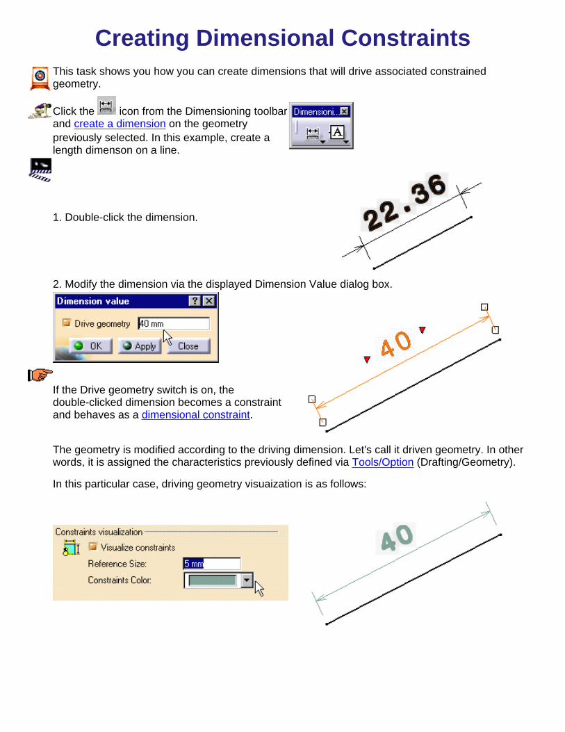
Creating Dimensional ConstraintsThis task shows you how you can create dimensions that will drive associated constrainedgeometry.
Click the icon from the Dimensioning toolbarand create a dimension on the geometrypreviously selected. In this example, create alength dimenson on a line.
1. Double-click the dimension.
2. Modify the dimension via the displayed Dimension Value dialog box.
If the Drive geometry switch is on, thedouble-clicked dimension becomes a constraintand behaves as a dimensional constraint.
The geometry is modified according to the driving dimension. Let's call it driven geometry. In otherwords, it is assigned the characteristics previously defined via Tools/Option (Drafting/Geometry).
In this particular case, driving geometry visuaization is as follows:

SHIFT keyboard switch allows deactivating autodetection.
CONTROL keyboard switch allows locking the constraint currently created and thereby ty to createothers.
The constraint visualization defined characteristics can be visualized on the condition you activated
the Show Constraints command.
Manipulating AnnotationsThe Interactive Drafting workbench lets you manipulate annotations. The tasksdescribed in this section are presented in the following table:
Tasks


Creating a Free TextThis task shows you how to create a text element. This text is a free text and may either wrapor not wrap. This text is assigned an unlimited width text frame even though this text mayreach the frame boundary.
Create a rectangle.
1. Click the Text icon from theAnnotations toolbar.
2. Click in free space to define alocation for the text.
At this step, you may decide that you want thetext to be wrapped. For this, click in the freespace and then drag a frame correspondingto the text horizontal boundary.
The Text Editor dialog box is automaticallydisplayed.
3.Enterthetext inthedialogboxeditionfield.
Thetextautomaticallyappearson thedrawingas youareenteringit in theTextEditordialogbox.

In the case you created a wrappedtext the text appears as shownoposite:
4.Click again in free spaceor select a command iconto end the text creation.
The resulting text appearsas shown opposite:
If you click the Select icon to end the text creation, the text remains highlighted so thatyou can modify it.Note that using the toolbar you may define the anchor point, text size and justification. Youcan set text properties either before or after you create text. Please refer to Setting TextProperties.


Creating an Associated Text fromScratch
This task shows how to create a text which you want to be associated to anelement. It also shows you how this text will remain associated with the element.Open the Brackets_views.CATDrawing document from the\online\samples\IntDrafting directory. Create diameter dimensons.
1.Click the Text
icon fromthe Annotationstoolbar.2. Select anelement. Here,we will usea dimension.
The text frameis displayed aswell as the TextEditor dialogbox.
3. Enter the textin the TextEditor dialogbox.
4. Click in freespace or clickthe Select icon
to end thetext creation.

5. If needed,move thedimension to thedesired location.
The text remainsassociated tothe dimension.
Note that the text isassociative to the wholeselected element. In otherwords and in the case of adimension, if you move thedimension text exclusively,the associated text will notmove accordingly.
The table below lists the elements that can be assigned text:
Elements That Can Be Assigned Text
Annotationstextdatum featuredatum targetballoon
GD&Troughness symbolstextDimensions2D elementspointscirclescurvesarrowGenerative Draw Edges
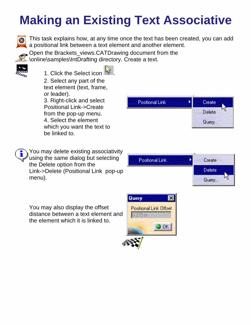
Making an Existing Text AssociativeThis task explains how, at any time once the text has been created, you can adda positional link between a text element and another element.Open the Brackets_views.CATDrawing document from the\online\samples\IntDrafting directory. Create a text.
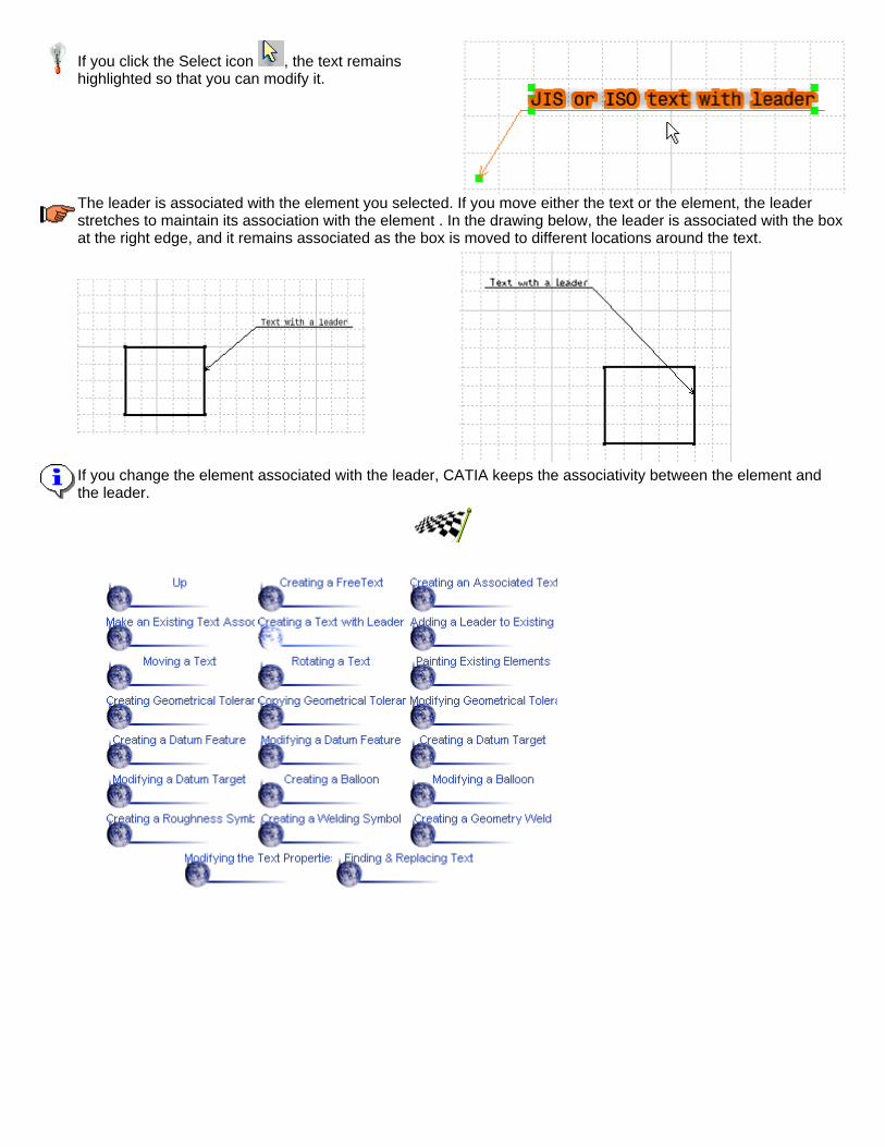
1. Click the Select icon .2. Select any part of thetext element (text, frame,or leader).3. Right-click and selectPositional Link->Createfrom the pop-up menu.4. Select the elementwhich you want the text tobe linked to.
You may delete existing associativityusing the same dialog but selectingthe Delete option from theLink->Delete (Positional Link pop-upmenu).
You may also display the offsetdistance between a text element andthe element which it is linked to.

Creating a Text With a LeaderThe Interactive Drafting workbench provides a command to create a text with a leader in free space or a text witha leader associated with an element.Note that leader lines are displayed in either of the following ways, based on the standard set for the currentdrawing.
Set the properties first if desired. You can set text properties either before or after you create text. Please refer toSetting text Properties for instructions.
1. Click the Leader icon from theAnnotations toolbar (Texts subtoolbar).
2. Click in free space to define a location forthe arrow end of the leader.
Instead of clicking in the free space, you can select an element you want the arrow end of the leader to beassociated with:
2D lines2D circles2D pointsCurvesGenerative Draw edges
As in the case of free text, you can create text that wraps. For this, click and drag the cursor to create a textframe.
The Text Editor dialog box displays.
4. Enter the text in the dialog box.
5. To end the text creation, click again infree space or select a command icon.
If you click the Select icon , the text remainshighlighted so that you can modify it.
The leader is associated with the element you selected. If you move either the text or the element, the leaderstretches to maintain its association with the element . In the drawing below, the leader is associated with the boxat the right edge, and it remains associated as the box is moved to different locations around the text.
If you change the element associated with the leader, CATIA keeps the associativity between the element andthe leader.

Adding a Leader to Existing Text
This task shows you how to add a leader to text that was previously created.
Open the Brackets_views.CATDrawing document from the \online\samples\IntDrafting directory.Create a simple text.Set the properties first if desired. You can set text properties either before or after you create text.Please refer to Setting text Properties for instructions.
1.Rightclickthetexttobeaddedaleader.
2.SelecttheAddLeadercommandthatappearsinthecontextualmenu.
3.Clicktheleaderarrowend.
Theleaderappears.
4. If needed, position the leader at the desired location.
To create as many leaders as required use Tools->Customize items and create the Add Leadercommand in a seperate toolbar. You will then be able to double-click the Add Leader commandand then click for locating the leader(s) to be created.

If severalelements areselected as youactivate theAdd Leadercommand, theselection iscleared and amessage asksyoufor selecting anannotation.
If you modify the text associated with the leader, associativity between the text and the leader iskept.

Moving a TextThis task explains how to move a text element using either the cursor or x, ycoordinates.
Open the Brackets_views.CATDrawing document from the\online\samples\IntDrafting directory. Create a text with a leader.
1. Click the Select icon .2. Selectany part ofthe textelement(text,frame,orleader) anddrag it to anewlocation.

If you want to move text using x,y coordinates, perform as follows:
1. Click the Select icon .2. Selectany part ofthe textelement(text, frame,or leader).3.Right-clickand selectMove fromthe pop-upmenu.4. Selecteither thePosition taborTranslationtab.Use the Position tab to move the text relative to the origin of thedrawing.Use the Translation tab to offset the text relative ot its currentlocation.
5. Enter thedesired x,ycoordinatesand selectApply.


Rotating a Text
This task explains how to rotate a text element.
Open the Brackets_views.CATDrawing document from the\online\samples\IntDrafting directory. Create a text with a leader.
1. Click the Select icon .
2. Select any part ofthe text element (text,frame, or leader).3. Right-click andselect Move from thepop-up menu.
4. Select the rotationtab.
5. Enter the desiredangle and selectApply. For instance,enter 30 degrees.

This is what you get.

Re-Applying Existing GraphicalProperties
This task shows you how to apply text graphical properties to texts alreadycreated. This is true for any type of Interactive Drafting element. In this task, wewill take text as an example.
Create texts.
1. Select the elements to be painted,for example text selected viamulti-selection.
2. Click the Painter icon from theGraphic Properties toolbar.
3. Select the text to be used as amodel for selected texts.
The texts selected are automaticallymodified.


Creating Geometrical TolerancesThis task shows you how to create a feature control frame for geometricaltolerance annotations.You can also copy an existing feature control frame and then edit its content tocreate a new one. See Copying a feature Control FrameOpen the Brackets_views.CATDrawing document from the\online\samples\IntDrafting directory.
1. Click the Geometrical Tolerance icon
from the Dimensioning toolbar(Tolerancing subtoolbar).
2. Select any element, a point in free space, a dimension or a text.
3. Select again to position the feature control frame.Selecting an element or a point in free space defines a position for the end of aleader.
If you select any element: If you select a point infree space:
If you select a dimension or a text element, no leader is displayed. The featurecontrol frame is positioned just below the element you selected.
If you select a dimension: If you select a textelement:

The Geometric Dimensioning And Tolerancing Parameters dialogbox displays.
Select to display in the Characteristic box only those symbols generallyconsidered appropriate for the type of element selected.
Select to display all characteristic symbols, regardless of the type ofelement selected.
4. In the Characteristic box, select a geometric characteristic for Line1.
5. Define any of the following values, as appropriate, for Line 1and/or Line 2:
diameter zonetolerance feature modifierprimary datum feature modifiersecondary datum feature modifiertertiary datum feature modifier
6. After you entered a value, press Enter or Tab to move to the nextfield.The feature control frame is updated as you define values for eachfield.

7. Click OK to confirm your operation and close the dialog box.

Copying Geometrical TolerancesThis task will show you how to copy an existing feature control frame and thenedit the content for creating a new one. See Copying a feature Control Frame.
1. Click on the feature control frame you want to copy.2. Right-click and select the Copy option from the contextual menu.3. Select the element to which you want the feature control frame tobe associated.4. Right-click and select the Paste option on the contextual menu.5. Double-click the copied feature control frame.6. In the filter Symbols box, make sure that the desired option isactivated.
Select to display in the Characteristic box only those symbolsgenerally considered appropriate for the type of element selected.
Select to display all characteristic symbols, regardless of theselected type of element.
7. Modify any of the values.
After you enter a value, press Enter or Tab to move to the next field.The feature control frame is updated as you define values for eachfield.
8. Click OK to confirm your operation and close the dialog box.


Modifying Geometrical Tolerances
This task shows you how to modify a geometrical tolerance.
1.Double-clickthe featurecontrol youwant tomodify.
The Geometric Dimensioning And Tolerancing Parameters dialog boxdisplays.
2. Modify any of the values.

3. Click OKto confirmyouroperationand closethe dialogbox.
4. Click inthe freespace tovalidate thegeometricaldimensionmodification.
In the filter Symbols box, make sure that the desired option is activated:
Select to display in the Characteristic box only those symbols generallyconsidered appropriate for the type of element selected.
Select to display all characteristic symbols, regardless of the type ofelement selected.


Creating a Datum FeatureThis task will show you how to create a datum feature.
Open the Brackets_views.CATDrawing document from the\online\samples\IntDrafting directory.
1. Click theDatumfeature icon
from theDimensioningtoolbar.
2. Select theattachmentpoint of thedatumfeature.3. Select theanchor pointof the datumfeature.The DatumFeaturedialog boxdisplays withthe datumfeaturecharacterstring.
4. Click OK.
CATIA provides a wysiwyg capability. In other words, when editing the characterstring, the modification is simultaneously taken into account.

The datum featureis created.
The datum feature is associative to the geometrical tolerance.

Modifying a Datum Feature
This task shows you how to modify a datum feature.
Open the Brackets_views.CATDrawing document from the \online\samples\IntDraftingdirectory. Create a datum feature.
1.Double-clickthe datumfeature youwant tomodify.
The ModifyText dialogbox displays.
2. Modify thedatum featurevalue.
3. Click OK toconfirm youroperation andclose thedialog box.
4. Click in thefree space tovalidate thedatumfeature modification.


Creating a Datum TargetThis task will show you how to create a datum target on a right projection view.
Open the Brackets_views.CATDrawing document from the\online\samples\IntDrafting directory.
1. Click the Datum
Target icon .2. Select theattachment point of thedatum target leader.3. Select the datumtarget anchor point.
4. The Datum Targetdialog box displays:enter the required field.5. The datum targetpreview is displayed.6. Click OK.
CATIA provides a wysiwyg capability. In other words, when editing thecharacter string, the modification is simultaneously taken into account.
The datum target iscreated.


Modifying a Datum Target
This task shows you how to modify a datum target.
Open the Brackets_views.CATDrawing document from the\online\samples\IntDrafting directory. Create a datum target.
1. Double-click thedatum target youwant to modify.
The Modify Textdialog box displays.
2. Modify any ofthe datum targetvalue.
3. Click OK toconfirm youroperation and closethe dialog box.
4. Click in the freespace to validatethe datumtarget modification.


Creating a BalloonThis task will show you how to create a balloon.
Open the Brackets_views.CATDrawing document from the \online\samples\IntDraftingdirectory.
1. Click the Balloon icon from the Annotations toolbar(Texts subtoolbar).
2. Select an element.
3. Click to define the balloonanchor point.
The Balloon Creation dialog boxdisplays:
4. Enter the desired characterstring.
5. Click OK to confirm youroperation.
CATIA provides a wysiwyg capability. In other words, when editing the character string, themodification is simultaneously taken into account.

Modifying a Balloon
This task shows you how to modify a balloon.
Open the Brackets_views.CATDrawing document from the\online\samples\IntDrafting directory. Create a balloon.
1. Double-clickthe balloon youwant to modify.
The Modify Textdialog boxdisplays.
2. Modify theballoon value.
3. Click OK toconfirm youroperation andclose the dialogbox.
4. Click in thefree space tovalidate theballoon modification.


Creating a Roughness SymbolThis task will show you how to create a roughness symbol.
Open the Brackets_views.CATDrawing document from the \online\samples\IntDrafting directory.
1. Click the Roughness symbol icon from the Annotations toolbar.
2. Select the attachment point ofthe roughness symbol.
The Roughness Symbol Editor dialog box displays:3. Enter the required field.4. Click OK.
Note that you can use the following symbols:

The roughness symbol is created.
You may modify the roughness symbol position by dragging it to the required location.
At any time, you can modify the roughness symbol. For this, double-click the roughness symbol to be modified and enterthe modifications in the Roughness Symbol Editor dialog box.

Creating a Welding SymbolThis task will show you how to create a welding symbol.
Open the Brackets_views.CATDrawing document from the\online\samples\IntDrafting directory.
1. Click theWeldingSymbol iconfrom theAnnotationstoolbar(Symbolssubtoolbar).
2. Selecttheattachmentpoint of theweldingsymbol3. Select afirstelement.4. Select asecondelement.
The Welding creation dialog box displays
3. Enter therequiredfield.4. Click OK.

The weldingsymbol iscreated.
You may modify the welding symbol position by dragging it to the requiredlocation.
At any time, you can modify the welding symbol. For this, double-click thewelding symbol to be modified and enter the modifications in the displayed dialogbox.

Creating a Geometry WeldThis task will show you how to create a geometry weld.
Open the Brackets_views.CATDrawing document from the\online\samples\IntDrafting directory.
1. Click the Weld icon fromthe Annotations toolbar(Symbols subtoolbar).
2. Select a first element.3. Select a second element.
The Welding Editor dialog box displays:
3. For example, modify thethickness from ten to five.4. Click OK.
The geometry weldingsymbol is created as shown:

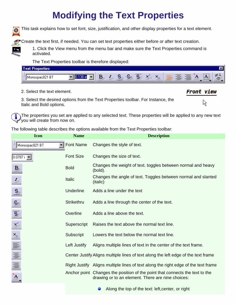
Modifying the Text PropertiesThis task explains how to set font, size, justification, and other display properties for a text element.
Create the text first, if needed. You can set text properties either before or after text creation.1. Click the View menu from the menu bar and make sure the Text Properties command isactivated.
The Text Properties toolbar is therefore displayed:
2. Select the text element.
3. Select the desired options from the Text Properties toolbar. For Instance, the Italic and Bold options.
The properties you set are applied to any selected text. These properties will be applied to any new textyou will create from now on.
The following table describes the options available from the Text Properties toolbar:Icon Name Description
Font Name Changes the style of text.
Font Size Changes the size of text.
Bold Changes the weight of text. toggles between normal and heavy(bold).
Italic Changes the angle of text. Toggles between normal and slanted(italic)
Underline Adds a line under the text
Strikethru Adds a line through the center of the text.
Overline Adds a line above the text.
Superscript Raises the text above the normal text line.
Subscript Lowers the text below the normal text line.
Left Justify Aligns multiple lines of text in the center of the text frame.
Center Justify Aligns multiple lines of text along the left edge of the text frame
Right Justify Aligns multiple lines of text along the right edge of the text frame
Anchor point Changes the position of the point that connects the text to thedrawing or to an element. There are nine choices:
Along the top of the text: left,center, or right

Along the vertical center of text: left, center or rightAlong the bottom of the text: left, center, or right
Frame Draws a single-line frame around the text.

Finding And Replacing TextThis task explains first how to locate a string of characters and then how toreplace it in the following elements:
balloonsdatum featuresdatum targetsdimensionstext elements
Open the Brackets_views.CATDrawing document from the\online\samples\IntDrafting directory.
1. In the menu bar, select theEdit->Find items.The Find dialog box isdisplayed:
2. Select any of the optionalsetting , as appropriate:
3. Enter the text you want to find and select . If the textexists in the drawing, the first instance found in search is highlighted.
4.Select to search for other instances.
Each time, an instance of the text string is found, you can replace it with a new
string. To do this, type in the replacement text and select .5. A pop-up window isdisplayed when the search iscomplete.
6. Click OK to end your search.
7. Select to quit theFind dialog box.

Now, to replace a string of characters proceed as follows:
1. In the menu bar, selectEdit->Replace.The Replace dialog box isdisplayed:
2. Select any of the optional settings as appropriate.
3. Key in the "find"string and select . If the string exists inthe drawing , the first instance found in the search is highlighted.4. Key in the replacement text.5. select one of the replace options:
To replace only the highlighted instance of the text,
select .To replace all instances of the text, select
.
6. If needed, select to search for other instances.7. The search Complete pop-up window displays.8. Click OK and quit the Replace dialog box.

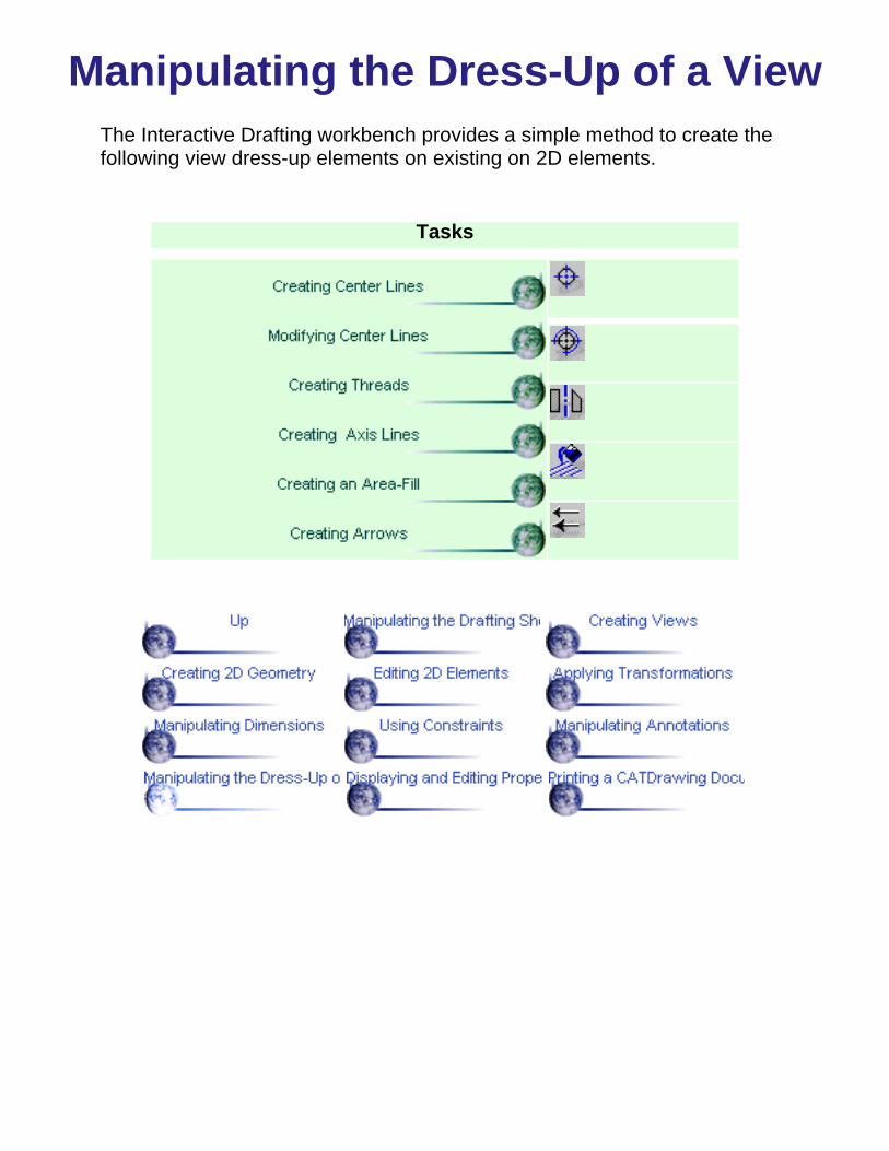
Manipulating the Dress-Up of a ViewThe Interactive Drafting workbench provides a simple method to create thefollowing view dress-up elements on existing on 2D elements.
Tasks

Creating Center LinesThis task will show you how to apply center lines to a circle.
Open the Brackets_views.CATDrawing document from the \online\samples\IntDraftingdirectory.
1. Click the Center line
icon from theDressup toolbar (Axisand Threads subtoolbar).
2. Select a circle.
The circle isautomatically appliedcenter lines.
You may create a center lineaccording to a linear reference.
1. Click the center line with a
reference icon .2. Select the circle to beapplied a center line.3. Select the reference line.
The center line created is associative with the reference line.
You may create a center lineaccording to a circular reference (apoint or a circle).
1. Click .2. Select the circle to beapplied a center line.3. Select the reference circle.

You can multi-select circles before you enter the command and thereby apply center linesto the selected circles.

Modifying Center LinesThis task will show you how to modify a center line.
Open the Brackets_views.CATDrawing document from the\online\samples\IntDrafting directory. Create center lines.
1. Click thecenter line.Green end pointsappear.
2. Select anyend point anddrag to the newposition. The center lineextremity lengthis modifiedglobally.
Now to modify the center line extremity length locally:

1. Click thecenter line.Green end pointsappear.2. Press the CtrlKey whileselecting anyend point anddrag to the newposition.
The center lineextremity lengthis modifiedlocally.
Multi-selection can be performed to modify center lines
You can also modify the center line using the contextual menu via the Propertiesdialog box.
The same method applies to axis lines.

Creating ThreadsThe Interactive workbench provides two commands to create threads. You caneither create a thread with a reference or without a reference.
This task will show you how to apply a thread to a hole without a reference firstand with a reference.Open the Brackets_views.CATDrawing document from the\online\samples\IntDrafting directory.
1. Click theDrawing window,
and click fromthe Axis andThreads toolbar.Activating this commanddisplays two options inthe Options toolbar.2. Select either the"Tap" or the "Thread"type.
The "Tap"type isactivated bydefault3. Select the "Thread"type.4. Select a circle to beapplied a thread.
CATIA allows multiselection of 2D elements.
The thread that appears on the circle is assigned a standard radius andrepresentation (compliant with the selected standard). The thread isautomatically "thread" type.
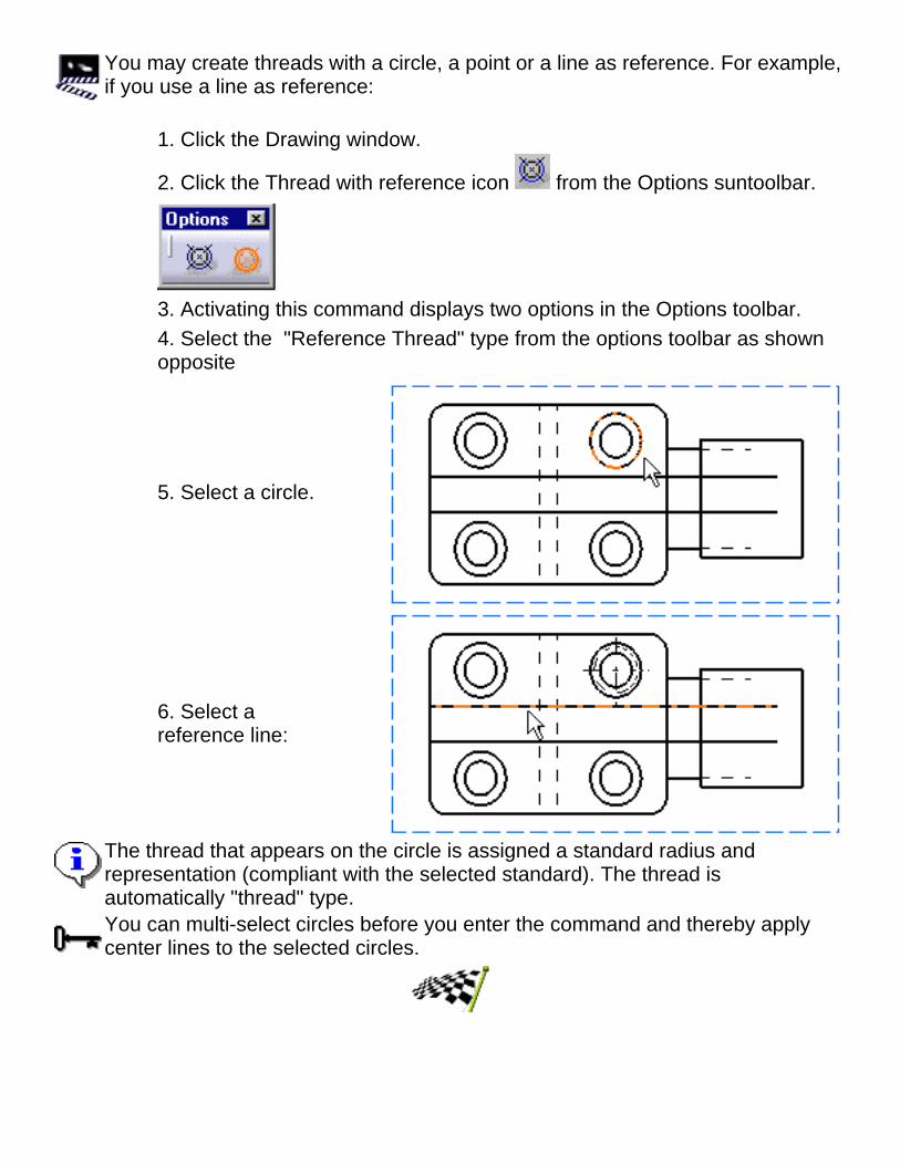
You may create threads with a circle, a point or a line as reference. For example,if you use a line as reference:
1. Click the Drawing window.
2. Click the Thread with reference icon from the Options suntoolbar.
3. Activating this command displays two options in the Options toolbar.4. Select the "Reference Thread" type from the options toolbar as shownopposite
5. Select a circle.
6. Select areference line:
The thread that appears on the circle is assigned a standard radius andrepresentation (compliant with the selected standard). The thread isautomatically "thread" type.You can multi-select circles before you enter the command and thereby applycenter lines to the selected circles.


Creating Axis LinesThis task will show you how to create an axis line.
Open the Brackets_views.CATDrawing document from the \online\samples\IntDraftingdirectory.
1. Click the Drawing window,and click the Axis Line icon
from the Dressup toolbar(Axis and Threads toolbar).
2. Select the two lines.
3. The axis line is created
If needed, you may select two non-parallel lines that are not colinearBoth for center lines and axis lines, a default overrun is created.If you need to modify an axis line, please refer to Modifying a center line as the methodis similar. Note that multiselection can be performed for modifying axis lines

Creating the Area-FillThis task will show you how to apply to an existing hatching pattern a new area-fill.
Open the Brackets_views.CATDrawing document from the \online\samples\IntDraftingdirectory.
Hatching patterns can only be applied to area-fills resulting from sketched elements.
1. Click the Drawing window, and click the pattern chooser from the GraphicProperties toolbar.
The Patterndialog boxdisplays:2. Select therepresentationyou need.
3. Click withinthe area to befilled.

If you perform modifications to the filled area, the pattern will be modified accordingly.
Make sure the view is active.

Creating ArrowsThis task will show you how to create an arrow. For example to precise the kindof hole to be applied.Open the Brackets_views.CATDrawing document from the\online\samples\IntDrafting directory.
1. Click the Drawingwindow, and selectthe Arrow commandfrom the menu bar . 2. Click a point.
3. Click anobject.
The arrow and the selected object are associative.

You may also either indicate two points or select two objects.
If you need to edit thearrow, use the green endpoints or right-click thearrow and select theproperties options.You can modify itsgraphical visualization andlocation.
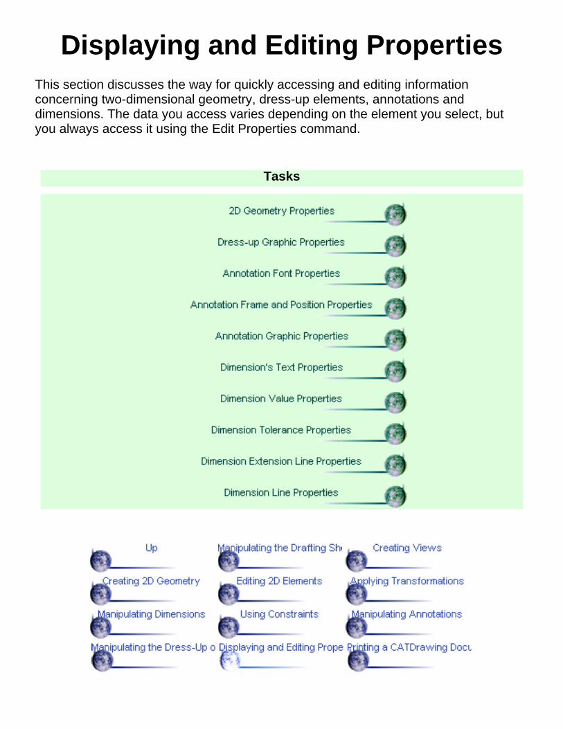
Displaying and Editing PropertiesThis section discusses the way for quickly accessing and editing informationconcerning two-dimensional geometry, dress-up elements, annotations anddimensions. The data you access varies depending on the element you select, butyou always access it using the Edit Properties command.
Tasks

Editing 2D Geometry FeatureProperties
Gathered in a same dialog box, the two-dimensional geometry propertiesconsists of different indications you will have sometimes to refer to. This taskexplains how to access and if needed, edit the information.Open a CATDrawing document.
1. Select a 2D element on the CATDrawing you opened.
2. Select the Edit Properties command or select the Propertiescommand from the contextual menu.ThePropertiesdialogboxdisplayswithFeaturePropertiesandGraphictabs.
TheFeaturePropertiestabeditstheNamefield.3. Enter a new name for the element in the field.The information displayed informs about the creation of the elements.4. Click OK to validate.


Editing Dress-Up Element GraphicProperties
Gathered in a same dialog box, the two-dimensional geometry propertiesconsists of different indications you will have sometimes to refer to. This taskexplains how to access and if needed, edit the information.Open a CATDrawing document.
1. Select a 2D element on the CATDrawing you opened.
2. Select the Edit-> Properties command or select the Propertiescommand from the contextual menu.The Properties dialog box displays, containing the Feature Propertiesand Graphic tabs that deal with Dress-up elements.

4. Click the Graphic tab and modify the line and curves color, forexample.
CATIA takes any modification into account. For more information ongraphic properties, please refer to CATIA-Infrastructure User's GuideVersion 5.
5. Click OK.

Editing Annotation Font PropertiesGathered in a same dialog box, the annotations properties consists of differentindications you will have sometimes to refer to. This task shows how to accessand if needed, edit the information.Open a CATDrawing document.
1. Select an annotation on the CATDrawing you opened.
2. Select the Edit ->Properties command or select the Propertiescommand from the contextual menu.The Properties dialog box displays, containing the following Font tab.


Editing Annotation Frame/PositionProperties
Gathered in a same dialog box, the annotations properties consists of differentindications you will have sometimes to refer to. This task shows how to accessand if needed, edit the information.Open a CATDrawing document.
1. Select an annotation on the CATDrawing you opened.
2. Select the Edit ->Properties command or select the Propertiescommand from the contextual menu.The Properties dialog box displays, containing the following Frameand Position tab.


Editing Annotations GraphicProperties
Gathered in a same dialog box, the annotations properties consists of differentindications you will have sometimes to refer to. This task shows how to accessand if needed, edit the information.Open a CATDrawing document.
1. Select an annotation on the CATDrawing you opened.
2. Select the Edit ->Properties command or select the Propertiescommand from the contextual menu.The Properties dialog box displays, containing the following Graphictab.

CATIA takes any modification into account. For more information on graphicproperties, please refer to CATIA-Infrastructure User's Guide Version 5.

Editing Dimension's Text PropertiesGathered in a same dialog box, the dimensions properties consists of differentindications you will havesometimes to refer to. this task explains how to access and if needed, edit theinformation.Open a CATDrawing document.
1. Select a dimension (whatever the type) on the CATDrawing you opened.
2. Select the Edit Properties command or select the Properties command fromthe contextual menu.The Properties dialog box displays, containing the following tabs dealing withdimensions:


Editing Dimension Value PropertiesGathered in a same dialog box, the dimensions properties consists of differentindications you will havesometimes to refer to. this task explains how to access and if needed, edit theinformation.Open a CATDrawing document.
1. Select a Dimension (whatever the type) on the CATDrawing you opened.
2. Select the Edit Properties command or select the Properties command on thecontextual menu.The Properties dialog box displays, containing the following Value tab.

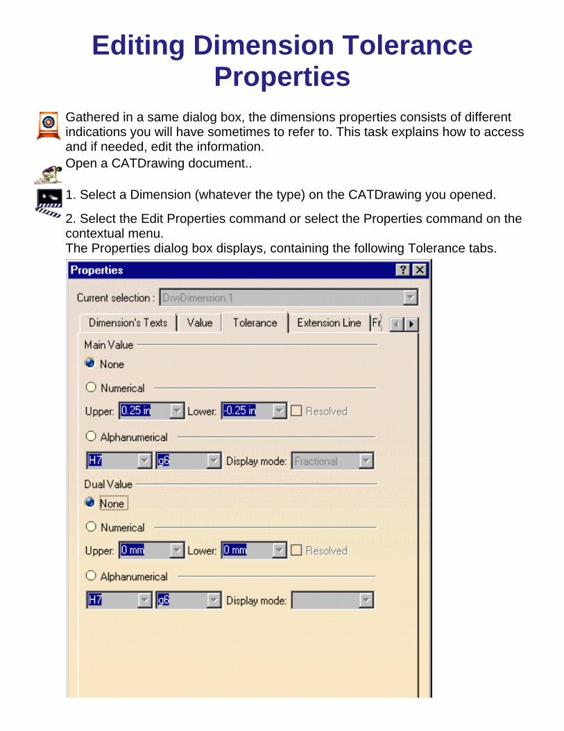
Editing Dimension ToleranceProperties
Gathered in a same dialog box, the dimensions properties consists of differentindications you will have sometimes to refer to. This task explains how to accessand if needed, edit the information.Open a CATDrawing document..
1. Select a Dimension (whatever the type) on the CATDrawing you opened.
2. Select the Edit Properties command or select the Properties command on thecontextual menu.The Properties dialog box displays, containing the following Tolerance tabs.


Editing Dimension Extension LineProperties
Gathered in a same dialog box, the dimensions properties consists of differentindications you will have sometimes to refer to. This task explains how to accessand if needed, edit the information.Open a CATDrawing document..
1. Select a Dimension (whatever the type) on the CATDrawing you opened.
2. Select the Edit Properties command or select the Properties command on thecontextual menu.The Properties dialog box displays, containing the following Extension Line tab.


Editing Dimension Line PropertiesGathered in a same dialog box, the dimensions properties consists of differentindications you will have sometimes to refer to. This task explains how to accessand if needed, edit the information.Open a CATDrawing document..
1. Select a Dimension (whatever the type) on the CATDrawing you opened.
2. Select the Edit Properties command or select the Properties command on thecontextual menu.The Properties dialog box displays, containing the following DImension Line tab.


Printing a CATDrawing Document
The Interactive Drafting workbench provides a simple method to print oneor more sheets inserted in your document.
Tasks

Printing a Document QuicklyThis task will show you how to quickly print a given sheet.
Open a CATDrawing document. Create a circle, a line and a profile on this document.
1. Select File -> Print Preview from the menu bar.
The Print Preview dialog box is displayed.2. Press OK.

3. Select File -> Print from the menu bar.The Print dialog box displays.
4. Click the required options from the box.5. Press OK.
You may print either all or given sheets (the sheet selected or a given number of existingsheets).
You may also print the views currently displayed on your screen (Current display option).

You may also choose the number of copies you need to print.
For details on Options, see CATIA - Infrastructure User's guide Version 5.By default the sheet to be printed will Fit to Printer Format. The printer default format will beused whatever the sheet format. Let's say the printer format is Portrait. If you check the optionsas described below, the sheet will be previewed and printed as follows.
Best Orientation/Fit to printer format/Clip to the sheet format

Fit to printer format/Clip to the sheet format

Clip to the sheet format

Best orientation/Clip to the sheet format

Let's start from a new drawing:

Best Orientation/Fit to printer format/Clip to the sheet format
Best Orientation/Fit to printer format


Printing a Document After ModifyingCurrent Display Settings
This task shows how to modify the settings of a document you will then print.
Create views on different sheets with the Landscape orientation.
1. Select File -> Print from the menu bar.The Print dialog box is displayed.2. ClicktherequiredPrinteroptionsfrom thedialogbox.3. ActivatetheCurrentdisplayoption.4. ClicktheOptionsoptionfrom thebox.
5. Ifneeded,select theColor tab.

6. Ifneeded,select theBannertab.
7. Ifneeded,select theVarioustab.8. ClickOK.
9. ClicktheSettingsoptionfrom thePrintdialogbox.TheLayoutdialog boxisdisplayed.10.Activatethe Fit inPageoption.11. Forexample,click thecenterswitch forpositioning

the sheetat thecenter ofthepreviewedlayout.12. PressOK.
13. Selectthe PrintPreviewoptionfrom thePrintdialogbox.The PrintPreviewdialog boxisdisplayed.14. PressOK.The Printdialog boxisdisplayed.15. PressOK tolaunch theprintingoperation.

Advanced TasksSee CATIA - Infrastructure User's guide Version 5 for details on DXF/DWG files.

Workbench DescriptionThis section contains the list of the icons and menus which are specific to InteractiveDrafting workbench.You may read these pages whenever you need to know greater details on these commandsdocumented in other parts of the guide.
Theme Purpose
Interactive Drafting MenuBar
Describe access to view and dimension creation, annotation andgeometry creation as well as sheet management
Interactive Drafting Toolbar Describe how to manipulate a CATDrawing and how to insert or editviews, dimensions, annotations sheets and sketcher or 2D elements
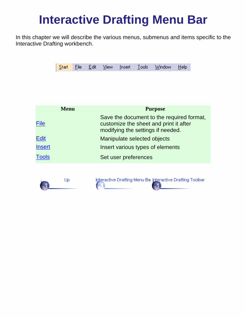
Interactive Drafting Menu BarIn this chapter we will describe the various menus, submenus and items specific to theInteractive Drafting workbench.
Menu Purpose
FileSave the document to the required format,customize the sheet and print it aftermodifying the settings if needed.
Edit Manipulate selected objectsInsert Insert various types of elements
Tools Set user preferences

FileFor all File menu items, see the CATIA Infrastructure User's Guide
I

EditAlso refer to the CATIA Infrastructure User's Guide.
For... See...
Background Creating a Frame Title Block

InsertFor... See...
Annotations... Annotations Creation
Dimensions... Creating Dimensions
Dressup... Manipulating the Dress-up of a view
Sketcher... Geometry Creation
Transformations... Creating Transformations
Constraints... Setting Constraints
Views... Creating Views
New Sheet...

ToolsAlso refer to the CATIA Infrastructure User's Guide.
For... See...
Line-Up Lining up Dimensions
Layers And Filters
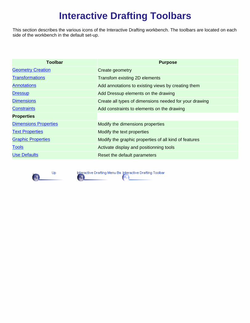
Interactive Drafting ToolbarsThis section describes the various icons of the Interactive Drafting workbench. The toolbars are located on eachside of the workbench in the default set-up.
Toolbar PurposeGeometry Creation Create geometryTransformations Transfom existing 2D elementsAnnotations Add annotations to existing views by creating themDressup Add Dressup elements on the drawingDimensions Create all types of dimensions needed for your drawingConstraints Add constraints to elements on the drawingPropertiesDimensions Properties Modify the dimensions propertiesText Properties Modify the text propertiesGraphic Properties Modify the graphic properties of all kind of featuresTools Activate display and positionning toolsUse Defaults Reset the default parameters

Geometry Creation
See Points See ThreePoint Arc
See Points UsingCoordinates See Profiles
See Equidistant Points See Curves
See Lines SeeRectangles
See Circles See Orientedrectangles
See Three Point Circle SeeParallelograms
See Circles UsingCoordinates See Hexagons
See Ellipses See OblongProfiles
See Arcs See OblongArcsSee KeyholeProfiles

Transformations
See Modifying aCorner
See Creating SymmetricalElements
See Modifying aChamfer See Translating Elements
See TrimmingElements See Rotating Elements
See BreakingElements See Scaling Elements

Annotations
See Creating Text
See Creating & Editing Text with Leader
See Manipulating Geometrical Tolerances
See Creating a Datum Feature
See Creating a Datum Target
See Creating a Balloon
See Creating a Roughness Symbol
See Adding a Leader

Dressup
See Creating a Center Line and Modifying a Center line
See Creating a Center Line and Modifying a Center line
See Creating a Thread
See Creating a Thread
See Creating an Axis Line
See Creating the Area-Fill
See Creating an Arrow

Dimensions
See Creating Dimensions
See Creating Coordinate Dimensions

Constraints
See Setting Constraints

Text Properties
See Setting Text Properties

Graphic Properties
See Displaying and Editing Dress-Up Element Properties

Tools
See Helpful Tools
See Helpful Tools
See Setting Constraints
See Setting Constraints
See Helpful Tools

Use Defaults
Resets to default parameters

Views
See Creating Views

CustomizingThis section mentions the different types of setting customization you can perform. Thetasks you can perform are:
Tasks
Setting a grid
Customizing Constraints
Customizing Geometry Creation
Customizing General Settings
Customizing Autodetection
Customizing Company Standard Management

Glossary
Aabsolute position A sheet coordinates.angle dimension Dimension applied to one or two linear elements or to circular
elements.
Cchained dimension Dimension presentation mode made of a systemchamfer dimension Dimension applied to a chamfer
Ddatum feature An element defining a contacting surface on a part.
datum target An element defining a contacting surface on a part andrepresented by spherical or pointed locating pins.
detail sheet A sheet that is used as an intermediate catalog for positioning2D geometry elements that will be instantiated afterwards.
diameter dimension dimension representing either a radius or a diameter.distance dimension dimension representing the dimension between two elements be
they linear or circular type.ditto An instantiation of a 2D element that is stored on a detail sheet.document A common unit of data (typically a file) used in user tasks and
exchanged between users. When saved on disk, a document isgiven a unique filename by which it can be retrieved.
dress-up A graphical attribute of a 2D element.
Oobject In the Drafting workbench, there are two kinds of object:
activated and selected. The view frame of an activated object isdisplayed in red.
Ppart A 3D entity obtained by combining different features in the Part
Design workbench.

Rradius dimension Dimension applied to a circle, semi-circle or arc of a circle.
Ssheet A set of views. Several sheets may be created in the Drafting
workbench.standard The international conventions that are supported in the Drafting
workbench: ANSI, ISO and JIS.
Ttemplate In the Drafting workbench, an object that is included in the
document (for example, the title block).title block A frame which contains the title block.
Vview frame A square or rectangular frame that contains the geometry and
dimensions of the view.
Index
Aarea-fill ,arrow , axis line ,
Bballoon ,Break command
Ccenter line , commands
BreakCircleCircle with center point coordinatesPointPoint specifying coordinates
Coordinate dimension , creating
area-fill
arrowaxis lineballooncenter linecoordinate dimensionsdatum featuredimensiondistance dimensionpoints
sheetthread
Ddatum featuredatum targetdimensionsdistance dimension , dressupDXF formatDXF geometry ,
Ggeometrical tolerance ,
Mmenu barmodifying center line distance dimension text
PPoint commandpoints
creating
Ssheet
creating

Ttextthreadtoolbar
Wworkbench