international journal of pure and applied mathematics...
TRANSCRIPT
BEHAVIOUR AND IMPACT OF CONCRETE DECK SLAB, SHEAR CONNECTOR
AND STEEL BEAM IN COMPOSITE BRIDGE
A.Mohan1 and M.Tholkapiyan2
Department of civil engineering, Vel tech high tech Dr.Rangarajan
Dr.Sakunthalaengineering college, Chennai, India.
Abstract-The goal of the project was to develop a
bridge design that utilizes standard components to
assemble an adaptable bridge. In-service composite
steel girder bridges typically experience a variety of
deterioration mechanisms during their service lives,
ranging from cracking, spalls, and delimitations in the reinforced concrete deck to corrosion in the steel
girders. To date, several inspection techniques and
novel technologies have been widely implemented to
identify and measure different sources of defects
associated with bridge systems, especially within the
concrete deck. Despite successful implementation of
these evaluation methodologies, in this paper, the
impact of corrosion-induced subsurface deck
delimitation on the overall behavior and performance of
steel–concrete composite bridges is investigated using
finite element simulation and analysis. The accuracy
and validity of the modeling approaches were assessed
through a comparison to experimental data available in literature. A sensitivity study was performed to
investigate the influence of deck deterioration on the
system-level performance, load distribution behavior,
and failure characteristics of two representative
composite steel girder bridges.
Keywords: Deck slab, Shear connector, Steel Beam, Composite bridge.
1. Introduction
The composite bridge concepts cover the span range of
about 15 m to 50 m to link the traditional span lengths
of composite bridges – by that range they cover about 75 % of all span requirements for road bridges. Within
the scope of the project an extensive test program has
been performed including numerical simulations with
parameter and sensibility studies.
The test program has covered:
- Serviceability and fatigue tests with hybrid girders
- Push-out tests with dismountable shear connectors
and shear stud ∅ 25 mm
- Behavior of joints of partially- and fully prefabricated
slabs
- Fatigue tests on special joints of beams
- Plate buckling of stocky and slender webs
Furthermore software has been developed to verify
different kinds of constructions and enable a very fast
static calculation by the practical engineer.
Steel Concrete Composite (SCC) bridges are popularly
constructed throughout the World. Total shrinkage
strain in deck slab concrete of SCC bridges may be taken as 0.0003 (as per IRC-22, 1986). Reinforced
concrete slab on top of PSC girders, also come under
the purview of Composite construction.
(G.Radhakrishnan, 2009).But due to practical problems
composite construction using reinforced concrete slabs
on top of steel girders are more familiar now a day’s&
RDSO also insists Railways to go with reinforced
concrete slab on top of steel girders in ROB areas. Thus
using a reinforced concrete slab on top of steel girders
is an economical and popular form of construction for
highway & in Railway bridges. It can be used over a
wide range of span sizes.
A composite material (also called a composition material or shortened to composite) is a material made
from two or more constituent materials with
significantly different physical or chemical
properties that, when combined, produce a material
with characteristics different from the individual
components, ( IJARET, 2103). The individual
components remain separate and distinct within the finished structure. The new material may be preferred
for many reasons: common examples include materials
which are stronger, lighter, or less expensive when
compared to traditional materials.
Typical engineered composite materials include
• Composite building materials, such
as cements, concrete
• Reinforced plastics, such as fiber-reinforced
polymer
• Metal composites
• Ceramic composites (composite ceramic and
metal matrices)
Physical property
• The physical properties of composite materials are
generally not isotropic (independent of direction of
applied force) in nature, but rather are
International Journal of Pure and Applied MathematicsVolume 115 No. 7 2017, 247-255ISSN: 1311-8080 (printed version); ISSN: 1314-3395 (on-line version)url: http://www.ijpam.euSpecial Issue ijpam.eu
247
typically anisotropic (different depending on the
direction of the applied force or load). For instance,
the stiffness of a composite panel will often depend
upon the orientation of the applied forces and/or
moments. Panel stiffness is also dependent on the
design of the panel. For instance, the fiber
reinforcement and matrix used the method of panel
build, thermos set versus thermoplastic, type of
weave, and orientation of fiber axis to the primary
force. • In contrast, isotropic materials (for example,
aluminum or steel), in standard wrought forms,
typically have the same stiffness regardless of the
directional orientation of the applied forces and/or
moments.
• The relationship between forces/moments and
strains/curvatures for an isotropic material can be described with the following material
properties: Young's Modulus, the shear
Modulus and the Poisson's ratio, in relatively
simple mathematical relationships. For the
anisotropic material, it requires the mathematics of
a second order tensor and up to 21 material
property constants. For the special case of
orthogonal isotropy, there are three different
material property constants for each of Young's
Modulus, Shear Modulus and Poisson's ratio—a
total of 9 constants to describe the relationship
between forces/moments and strains/curvatures.
• Techniques that take advantage of the anisotropic properties of the materials include mortise and
tension joints (in natural composites such as wood)
and Pi Joints in synthetic composites.
1.1. Important terms
Composite Members
Structural members comprising prefabricated structural
units of steel, prestressed concrete, or reinforced
concrete and cast-in-situ concrete connected together in
such a manner that they act monolithically. (IJARET,
2103)
Shear Connectors
Structural elements, such as anchors, studs, channels
and spirals, intended to transmit the horizontal shear
between the prefabricated member and the cast-G-situ
concrete and also to prevent vertical preparation at the
inter-face.
Composite Action
For the purpose of design, if the prefabricated unit is
adequately supported before placing of the in-situ
concrete, it shall be designed to sustain self-load only. If the load of the formwork, constructional live load
and the in-situ concrete is carried directly by the
prefabricated unit without adequate props, this
additional load shall also be accounted for in addition
to self-load. The composite section shall be designed
for all the loads imposed on the member taking note of
the fact that the composite action of the member is
effective only for the loads imposed after the composite
action has started to function. ( Vikash Khatri, Pramod
Kumar Singh, 2012)
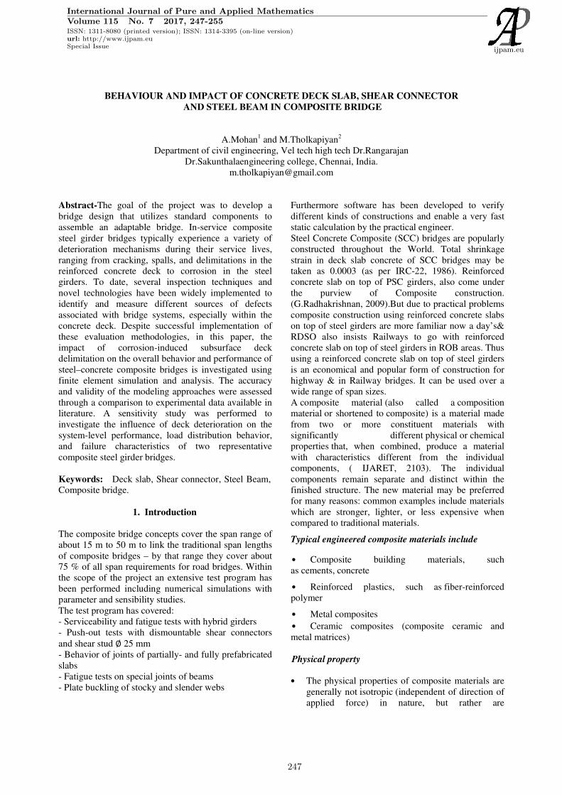
Figure 1. Principles of composite construction
Equivalent Section
For prefabricated units in prestressed concrete or
reinforced concrete, consideration shall be given to the
different module of elasticity of the concrete of the
precast and of the in-situ portions.( Vikash Khatri,
Pramod Kumar Singh, 2012)
For prefabricated units in steel, the effective gross area
of concrete slab shall be converted into the
corresponding equivalent area of steel. This shall be
done by dividing the effective area of the concrete slab
by the modular ratio.
Modulus of Elasticity
The values of module of elasticity of steel and concrete
shall be taken in accordance with requirements of the
relevant Indian Standard codes. The modular ratio shall
be also calculated on the. Basis of these modules of
elasticity except where otherwise laid down in the
relevant design codes.
Castellation’s
Protrusions or recesses on the top surface of the
prefabricated concrete units to provide the necessary
monolithic action between the cast-in-situ concrete and
prefabricated units.
1.2. Beam and slab construction (Composite
Bridges)
International Journal of Pure and Applied Mathematics Special Issue
248
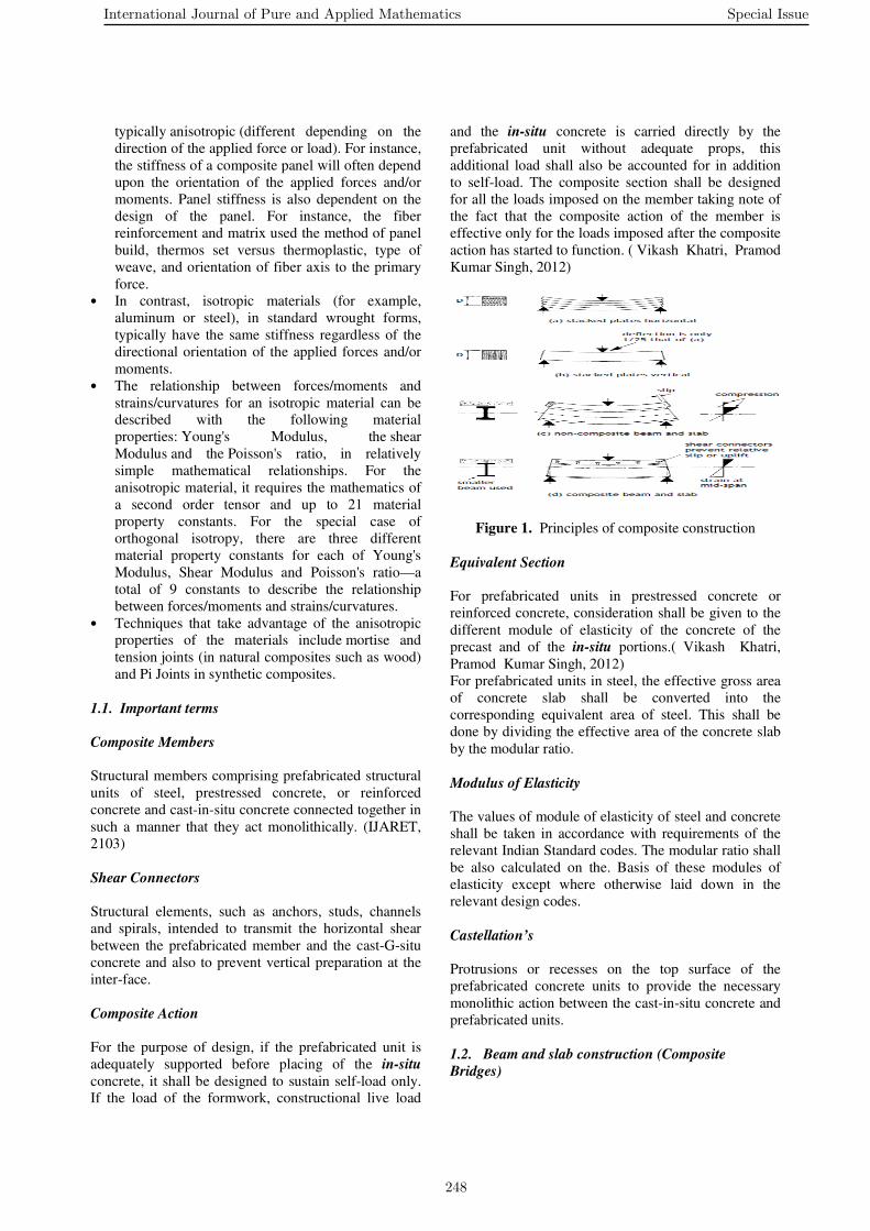
The form of construction considered in this publication
is the beam and slab type, where a reinforced concrete
deck slab sits on top of several I-section steel girders,
side-by-side, and acts compositely with them in
bending. It is one of the most common types of recent
highway bridge in construction .A typical cross section,
for a composite bridge two-lane road with footways, is
shown in Figure 1.
Figure 2. Typical cross section of a composite bridge
two-lane road with footways
Composite action is generated by shear connectors
welded on the top flanges of the steel girders. The
concrete slab is cast around the connectors. This effectively creates a series of parallel T-beams, side by
side. The traffic runs on a non-structural wearing
course on top of the slab (there is a waterproofing
membrane between). The load of the traffic is
distributed by bending action of the reinforced concrete
deck slab, either transversely to the longitudinal beams
or, in some cases, by longitudinal bending to cross-
beams and thence transversely to a pair of longitudinal
main beams. The steel girders can be of rolled section,
for fairly short spans, or can be fabricated from plate.
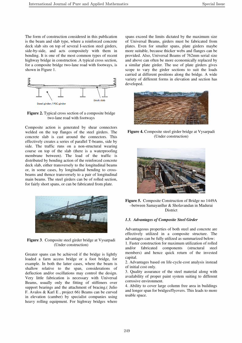
Figure 3. Composite steel girder bridge at Vysarpadi
(Under construction)
Greater spans can be achieved if the bridge is lightly
loaded a farm access bridge or a foot bridge, for
example. In both the latter cases, where the beam is
shallow relative to the span, considerations of
deflection and/or oscillations may control the design.
Very little fabrication is necessary with Universal
Beams, usually only the fitting of stiffeners over
support bearings and the attachment of bracing.( Julio
F. Avalos & Karl E , project 66) Beams can be curved in elevation (camber) by specialist companies using
heavy rolling equipment. For highway bridges where
spans exceed the limits dictated by the maximum size
of Universal Beams, girders must be fabricated from
plates. Even for smaller spans, plate girders maybe
more suitable, because thicker webs and flanges can be
provided. Also, Universal Beams of 762mm serial size
and above can often be more economically replaced by
a similar plate girder. The use of plate girders gives
scope to vary the girder sections to suit the loads
carried at different positions along the bridge. A wide
variety of different forms in elevation and section has developed.
Figure 4. Composite steel girder bridge at Vysarpadi
(Under construction)
Figure 5. Composite Construction of Bridge no 1449A
–between Samayanllur & Sholavandan in Madurai
District
1.3. Advantages of Composite Steel Girder
Advantageous properties of both steel and concrete are effectively utilized in a composite structure. The
advantages can be fully utilized as summarized below:
1. Faster construction for maximum utilization of rolled
and/or fabricated components (structural steel
members) and hence quick return of the invested
capital.
2. Advantages based on life-cycle-cost analysis instead
of initial cost only.
3. Quality assurance of the steel material along with
availability of proper paint system suiting to different
corrosive environment.
4. Ability to cover large column free area in buildings
and longer span for bridges/flyovers. This leads to more
usable space.
International Journal of Pure and Applied Mathematics Special Issue
249

5. Reinforced cement concrete (RCC) slab is in
compression and steel joist is in tension. Hence, most
effective utilization of the materials can be achieved.
6. Better seismic resistance i.e. best suited to resist
repeated earthquake loadings, which require a high
amount of ductility and hysteretic energy of the
material/structural frame.
7. Composite sections have higher stiffness than the
corresponding steel sections (in a steel structure) and
thus bending stresses as well as deflection are lesser. 8. Keeping span and loading unaltered, a lower
structural steel section (having lesser depth and weight)
can be provided in composite construction, compared
to the section required for non-composite construction.
9. Reduced beam depth reduces the story height and
consequently the cost of cladding in a building and
lowers the cost of embankment in a flyover (due to lower height of embankment).
10. Reduced depth allows provision of lower cost for
fire proofing of beam’s exposed faces.
11. Cost of formwork is lower compared to RCC
construction.
12. Cost of handling and transportation is minimized
for using major part of the structure fabricated in the
workshop.
13.Easy structural repair/modification/maintenance.
14. Structural steel component has considerable scrap
value at the end of useful life.
15. Reductions in overall weight of structure and
thereby reduction in foundation costs. 16. More use of a material i.e. steel, which is durable,
fully recyclable on replacement and environment
friendly.
1.4. Some of the guidelines available for Composite
(Steel) Construction
I. These girders are welded type.
ii. End diaphragm girders should be provided along the
alignment of the bearing so that the entire span at one
end can be lifted with help of synchronous jacks for
attending bearings etc.
Cross bracing should be provided square to the girder
alignment. iii. All field joints of cross bracings and end
diaphragms are planned with High Strength Friction
Grip Bolts.
iv. Stud type/ flexible shear connectors are provided.
Rigid shear connectors of structural steel section
welded on top flange should not be provided.
v. Provision of Abutment/pier at railway boundary is
not mandatory. Standard span should be planned over
the railway track. Adjacent spans can also be of
required standard span.
1.2. Super Structure
1.2.1. Static System
This Design comprises single and continues composite
bridges with different levels of prefabrication for the
concrete slab. The concrete slab consists out of a solid
slab or a partially- as well as fully prefabricated deck
elements. For the main girders rolled and welded)
sections (including LP plate sections) can be used. The
amount of the main girders is depending on the
required road width or -class. Solid slabs need a
complete formwork before concreting the bridge deck.
By using fully prefabricated slabs the openings for the shear connectors in the elements (pockets or covered
channel) and the joints between the elements have to be
filled with mortar. By pre-stressing the fully
prefabricated elements before grouting the joints
between the elements can be closed up to a minimum.
Partially prefabricated elements are the formwork
during casting and shall also be used later as a part of the total slab height. The distance between the main
girders can be determined by varying the slab thickness
and the used slab technique (e.g. partially prefabricated
slab, slab = 10 + 20 = 30 cm
Max birder Distance ≈ 3.00 m). An appealing design of the
superstructure can be reached by a slenderness of about
L / h = 25
(L = span length, h = total construction height).
After completion of the slab all main girders are
connected in-between by the concrete slab. To
guarantee the stability of the main girders against
torsional-flexural buckling the girders shall be lateral
stiffened by using cross girders in the main axes of the piers and abutments only. These cross girders can be
designed in steel or in concrete. The bearings can be
placed under the cross girders or directly under the
webs of the main girder. Additional torsional stiffeners
can be applied to obtain a knuckle support in the
moment zero point. One main aspect of this design is
the erection of the bridge without cost-intensive temporary supports or propping’s. Furthermore the
casting sequences have to be considered for continues
bridges. The following Table 2-1 shows the
construction sequences for an in-situ casted solid slab
or a fully pre-fabricated slab (example for a two-span
bridge).( IJARET, 2103)
The steel girders are acting as simple beams during the first construction situation and are laterally supported
by the cross girders in the main axes. The dead load of
the steel girders is carried by these simple beams only
(System 1). After welding the hinge continues steel
beams are obtained which have to carry the partially- or
fully prefabricated deck elements as well as the solid
slab in the second construction situation (System 2). By
using fully prefabricated elements or a solid slab this
continues steel beams have to carry the dead load of the
solid slab or the fresh concrete and construction loads
only (System 2). By using partially prefabricated slabs
in the construction situation 3 a partial composite
action can be achieved by grouting the joints and pockets in the elements. The supplement fresh concrete
International Journal of Pure and Applied Mathematics Special Issue
250

and the construction loads are carried after the setting
of the mortar by the partial composite cross section
(System 3). The partially prefabricated elements are
now acting as one shell (e.g. for wind loads). The static
utilization of the partial composite action provides a
very economic and optimized construction. The last
construction situation (System 4) is the continues and
finished composite cross section considering the
cracked concrete in the area of the hogging moment
(simplification). On this static system infrequent (e.g. finished permanent loads like caps and guard-rails) and
frequent (e.g. traffic) loads are applied under
considering the time dependent behavior of the cross
sections (creep- and shrinkage effects). The relevant
forces for each construction phase are multiplied by
safety- and combination factors and summed up. With
the load combinations and the estimated cross sections the following checks for the ultimate limit state and the
serviceability state are performed:
Ultimate limit state (ULS) of the steel girder (System 1
and 2):
- Ultimate resistance against positive bending
- Ultimate resistance against negative bending
- Ultimate resistance against positive / negative bending
taking interaction of shear in account
- Ultimate resistance against shear
- Ultimate resistance against torsional-flexural buckling
Ultimate limit state (ULS) of the composite beam
(System 3 and 4):
- Ultimate resistance against positive bending - Ultimate resistance against negative bending
- Ultimate resistance against shear
- Ultimate resistance against negative bending taking
interaction of shear in account
- Bonding strength of the shear connectors, number of
shear connectors
- Ultimate resistance against torsional-flexural buckling Serviceability limit state (SLS) of the composite beam
(System 3 and 4):
- stress analysis
- Crack width limitation and check of minimum
reinforcement
- Deflection check to complete the design of a
structure, the following items has to be carried out, but is not considered in the design guide:
- Distribution of the shear connectors
- shear resistance of the concrete chord
- Check of the contour area of the shear connector
- fatigue design
- Vibration behavior of the structure could be checked
potentially (especially for slender structures using HSS
and HSC
1.2.2. Steel construction
The main girders should be prefabricated and painted
with protection against corrosion in the workshop before arriving on site. By using welded plates for the
girders the required cross sections can be suited very
well to the stress distribution.(FHAW,2013).A cost
optimized steel construction can be reached by using
hybrid girders with lower strength steel for the web and
higher strength steel for the flanges. The number of
different cross sections of welded plate girder in
longitudinal direction should be minimized to obtain a
small number of joints and different plate thickness. In
the frame of the ECSC-Project hybrid girders have
been tested under fatigue loads. A further decrease of weight can be achieved by using LP-plates with a
variable thickness in longitudinal direction; these LP-
plates are rolled by a few mills only. The main girders
are connected on support or in span by using welded as
well as bolted connections and temporary cams. In the
area of welded connections the corrosion protection has
to be removed before the welding procedure and has to be completed after finishing the welding activities. The
usual steel grades for composite bridges are S235, S355
or S460. By using special steel, e.g. HISTAR from
Profile ARBED, a reduction of steel strength according
to the steel thickness can be precluded.
2. Behaviour Of Bridge Structures
2.1. An Overview
Steel-concrete composite bridges provide an efficient
and cost-effective form of bridge construction. By
utilizing the tensile strength of steel in the main girder
and the compressive strength of concrete in the slab,
the bending resistance of the combined materials is
greatly increased and larger spans are made possible.
River Bridges are steel/concrete composite deck slab bridges. Combining the advantages of steel and
concrete, they can be constructed to a low structural
height that could never be realized with steel bridges
and PC bridges. They are simple in structure, consisting
mainly of shape steel, and outperform other types of
bridges in terms of the on workability.
River Bridges can be constructed with effective spans
ranging from about 10 to 40 meters and skew angles of
45 degrees or more and can be adapted to changes in
structural height according to their longitudinal
alignment. They are now compatible with continuous
girders, expanding their range of applications...
2.2. Features
2.2.1. Low structural height
From among all structural types, River Bridges can
achieve the lowest structural height.
2.2.2. Rapid construction
The construction weight of River Bridges is far lighter
than that of concrete-based bridges, so heavy
International Journal of Pure and Applied Mathematics Special Issue
251

equipment can be downsized. In addition, formwork
and scaffolding are no longer necessary as the bottom
panels function as deck slab formwork, resulting in the
reduction of the construction work period.
2.2.3. Minimization of LCC
The RC deck slabs, which are of a highly durable structure, are almost maintenance-free and also
contribute to the minimization of life cycle costs.
2.2.4. Design ability
River Bridges can offer not only a slender appearance
thanks to their low structural height but also impressive
landscaping design.
2.3. Features Of The Structure
2.3.1. Low structural height
The core feature of River Bridge is their low structural
height. The effective span-structural height ratio is 1/30
to 1/42, and the height of girder ends can be reduced to a minimal 30 cm.
When the gap between the estimated high water level
and the planned road height in an urban area is
inadequate, as is often the case, River Bridges can offer
a sufficient geometric line road form. The extension of
the access road can also be shortened by reducing the
structural height so that it will be easier to secure the
necessary surrounding land.
Figure 6. Relationship between structural height and
connected road
2.3.2. Deck slabs with high durability
The results of moving wheel load driving tests prove
that the RC deck slabs of River Bridges are equal to
composite deck slabs in fatigue durability. River
Bridges can serve for 100 years thanks to the fatigue durability of these deck slabs and of the steel
members.( Vaghefi K, Ahlborn T, Harris D, 2014)
2.3.3. Weight of steel materials
The core feature of River Bridges is their low structural
height. The effective span-structural height ratio is 1/30
to 1/42, and the height of girder ends can be reduced to
up to about 30 cm.
2.3.4. DFT is used for the main girders
Shear connectors play the important role of letting the
steel panels and concrete behave together in a
composite structure. River Bridges (KCSB) use DFT as shear connectors for the main girders. DFT (Deformed
Flange T-shape) is the T-shaped steel produced by
cutting half H-shaped steel (Deformed Flange H-shape)
with projected lines, which are formed on the external
surface of the flange at the stage of rolling. The height
of the main girders can be adjusted via the height of the
extended web.
3. Details Of The Structure
Figure 7. Cross section of structure
3.1. New technology (Hyper Bridge)
Hyper Bridges are composite rigid-frame bridges made
up of a River Bridge with steel-concrete composite
structure bridge piers (REED method bridge piers)
rigidly connected there.
Figure 8. Hyper bridge
• Reduced construction work period: Since the
bridge piers (REED method bridge piers) and the joints
are prefabricated, construction work can be performed
rapidly.
International Journal of Pure and Applied Mathematics Special Issue
252

• Lower structural height: The structural height
can be minimized by the superstructure design (River
Bridges).
• Improved earthquake resistance: The rigid-
frame structure gives Hyper Bridges higher earthquake resistance.
• Reduced maintenance costs: Maintenance costs
are reduced as the supports do not require maintenance.
• Better landscape: A superstructure with fewer
concave and convex portions presents a better
landscape.
Figure 9. Landscape Of Hyper Bridge
3.2. Basic Concept Of Composite Bridge Design
3.2.1. Applicable standard
The basic concept of design conforms to Specifications
for Highway Bridges Parts I to V (March 2002). The
“Design and Construction Work Guidelines for
Composite Deck Slab Bridges (draft): Composite Deck
Slab Bridge Research Center” applies to matters related to composite deck slab bridges.
3.2.2. Analysis method
In principle, design section force is calculated by
analyzing the grids formed by the main girders
consisting of bottom slabs for which the effective width
is taken into account, projected T-shaped steels (DFT)
and the extended webs. Simplified analysis can also be
applied to road bridges, such as right bridges or
pedestrian bridges.
3.2.3. Steel/Concrete composite structure
The pre-composition dead load is resisted by the cross
section of steel, and the post-composition dead load and
the live load are resisted by the composite cross
section. Compared with stud dowels, etc. for ordinary
composite girders, the steel/concrete composite
structure is inexpensive and lower in structural height,
as its integration depends on the adhesive force of
projections of DFT and concrete.
3.2.4. Two types of structure: solid type and hollow
type
The solid type is the standard structure for bridges with
an effective span of up to about 20 meters, whereas the
hollow type is for those with a longer span.
• Polystyrene foam is generally used for
embedded formwork.
• Hollow type bridges require coating on deck
slab reinforcing bars and the internal surface of the
hollow area.
Figure 10. Solid type bridge structure
Figure 11. Hollow type bridge structure
3.2.5. Shape of the steel girders
The standard shape of the steel girders is described
below.
• The DFT members are placed straight and
parallel to one another at equal intervals.
• The steel girders are level with one another in the
direction perpendicular to the center line of the
structure, and the cross fall of the road surface is leveled and adjusted with concrete.
3.2.6. Expansive concrete
To prevent cracking attributable to drying shrinkage,
expansive concrete is used.
3.3.7. Steel material requiring minimum
maintenance
For the purpose of saving labor required for future
maintenance, weather-resistant steel (bare type,
stabilizing-treated type, etc.) is used for the bottom and
side panels. Coating on plain steel is also available for
International Journal of Pure and Applied Mathematics Special Issue
253

bridges in urban areas and bridges that need to be
colored. (Beaton JL, Stratfull RF, 1973)
4. Conclusion
The global analysis of the bridge structure was
performed using a space frame model. The foundations were represented by springs at the underside of pile-cap
level, with stiffness’s determined from the geotechnical
pile group analyses taking into account the ground
conditions. Dynamic response spectral analysis was
used to assess the effect of earthquake loading on the
bridge structure and foundations. The design spectra for
the three limit states (serviceability, ultimate, and
structural integrity) were applied to the dynamic
analysis model.
Each limit state analysis was performed in three
excitation directions, using the vertical spectra, and the
horizontal spectra for both the longitudinal and
transverse directions. This determined the interaction
between the frequencies of ground motion and the
natural frequencies of the structure. The total mass
included in the analysis was all permanent vertical
loads and one third of type HA traffic loading on one
lane in each direction. The CQC (Complete Quadratic
Combination) was used for combination of the effects
from different modes. While the CQC method is reasonable for single action
effects (one excitation direction only), it is difficult to
apply to multiple action effects arising from different
excitation directions that interact with each other. For
the combination of excitation directions a 100:40:40
combination rule was used, with 100% contribution the
primary direction and a 40% combination from the other two directions. Each direction was taken in turn
as the primary direction, and all results were enveloped
to determine the worst load effects.
In cases where liquefaction of the soil was assumed to
have occurred, the foundation spring stiffness’s were
modified based on updated results from the
geotechnical pile group analyses. The spectral analyses
were then re-run for these cases to ensure any changes
in modal response due to liquefaction were taken into
account.
References
1) (SSE/Bridges/MDU) Southern Railway Civil
Engg News Digest April l2012.
2) “Quality control in fabrication of composite
girders”,G.Radhakrishnan(SSE/Bridges/MDU)
Southern Railway Civil Engg News digest September
2012.
3) “Comparative study of prestressed steel-concrete
composite bridge of different span length and girder
spacing”, Vikash Khatri, Pramod Kumar Singh and P.
R. Maiti International Journal of Modern Engineering
Research Vol.2, Issue 5, Sept-Oct 2012.
4) “Influence of skew angle on continuous
composite girder bridge”, Gholamreza Nourish &
Zahed Ahmadi. American Society of Civil Engineers.
5) Research in Engineering & Technology
(IJARET), Volume 4, Issue 5, 2013,
6) Federal Highway Administration (FHWA). National bridge inventory database. Washington, D.C:
Federal Highway Administration; 2013.
7) Vaghefi K, Ahlborn T, Harris D, Brooks C.
Combined imaging technologies for concrete bridge
deck condition assessment. J Perform Constr Facil
2014:04014102.
8) Beaton JL, Stratfull RF. Environmental influence
on the corrosion of reinforcing steel in concrete bridge
substructures. Sacramento, CA: California Department
of Highways; 1973.
9) Bažant ZP. Physical model for steel corrosion in
concrete sea structures — theory and application. J
Struct Div 1979;105(6):1137–66.
International Journal of Pure and Applied Mathematics Special Issue
254

255

256