introduction to nx7/70 series plc lab...
TRANSCRIPT
Introduction to NX7/70 Series PLCs
1 of 31 Publication OEMax-NX70-LB001A-EN-E - March 2005
Introduction to NX7/70 Series PLC OE Max Lab Manual
11-1-2004
TM
Maximum Value for OEMsSM
TMTM
Maximum Value for OEMsSMMaximum Value for OEMsSM

Introduction to NX7/70 Series PLCs
2 of 31 Publication OEMax-NX70-LB001A-EN-E - March 2005
Overview: In this lab, you will learn the basics of programming the OE Max NX7 and NX70 Series PLCs. It is a great way to introduce yourself to the NX Series PLCs. You will learn how fast and easy it is to solve simple applications without substantial setup time and without complex manuals. You will learn how similar the development environment is between NX7 and NX70 using WinGPC programming software. You will learn how to:
1) Create a ladder diagram program offline 2) Download a program over the serial port 3) Monitor program and data online 4) Save the project to flash eeprom in case of battery failure
Intended Audience: Anyone who wants to learn the basics of using the NX Series PLCs including engineers, technicians, maintenance personnel, and engineering managers. This lab is not intended for users already familiar with programming the NX Series PLCs.
Estimated Time: 30 Minutes
Prerequisites for the Lab: 1) Basic knowledge of PLCs and ladder programming 2) Personal computer with WinGPC Software already installed 3) NX7 and/or NX70 Demo System connected by serial port to the PC 4) Demo Kits have been configured – see Appendix A and B.
Welcome to: Introduction to NX7/70 Series PLCs

Introduction to NX7/70 Series PLCs
3 of 31 Publication OEMax-NX70-LB001A-EN-E - March 2005
NX-7 Demo Kit
NX-70 Demo Kit

Introduction to NX7/70 Series PLCs
4 of 31 Publication OEMax-NX70-LB001A-EN-E - March 2005
The following steps will show you how to create a new project for a specific controller. 1) From Windows Start, execute WinGPC. NOTE: The following is only an example screen capture. Your PC will look different for the screen captures.
2) From WinGPC, create a new project from the “Project->New Project” menu.
Let’s START. Create a new Project on your PC

Introduction to NX7/70 Series PLCs
5 of 31 Publication OEMax-NX70-LB001A-EN-E - March 2005
3) In the New Project window, type in a UNIQUE filename for the project (e.g. my_first_project123.PRJ). The filename must be unique else you will open up an already existing project.
Make sure the “PLC Model” and “CPU Type” match your Demo System. Click on “Open” when ready to continue.

Introduction to NX7/70 Series PLCs
6 of 31 Publication OEMax-NX70-LB001A-EN-E - March 2005
Example for NX7 PLC only.

Introduction to NX7/70 Series PLCs
7 of 31 Publication OEMax-NX70-LB001A-EN-E - March 2005
Example for NX70 PLC only.
Introduction to NX7/70 Series PLCs
8 of 31 Publication OEMax-NX70-LB001A-EN-E - March 2005
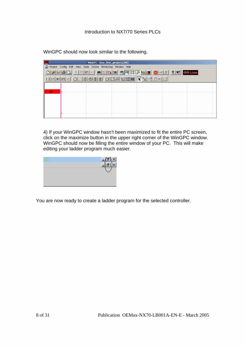
WinGPC should now look similar to the following.
4) If your WinGPC window hasn’t been maximized to fit the entire PC screen, click on the maximize button in the upper right corner of the WinGPC window. WinGPC should now be filling the entire window of your PC. This will make editing your ladder program much easier.
You are now ready to create a ladder program for the selected controller.

Introduction to NX7/70 Series PLCs
9 of 31 Publication OEMax-NX70-LB001A-EN-E - March 2005
The following steps will show you how to create a single rung program to turn an LED OFF and ON based upon an Input Switch. 1a) Click on the STR (Start Normally Open) button to select the “normally open” contact instruction. 1b) Next click on the first rung to create this instruction in your program. It should look like the following.
2) Enter “R0.0” for the STR instruction’s operand and hit the Enter key.
Create a Ladder Program

Introduction to NX7/70 Series PLCs
10 of 31 Publication OEMax-NX70-LB001A-EN-E - March 2005
NOTE: If you have accidentally clicked elsewhere in the window, you may have to reselect the instruction to enter the operand of “R0.0”. If this happens, simply click on the instruction, enter the operand, and click on “OK”.
You should know have a program that looks like the following:
NOTE: The STR instruction will make the rung execute based upon the value of an external input register “R000.00” (i.e. bit 00 of register 000). Refer to the User Manual for information on the NX controller memory registers and instruction set.

Introduction to NX7/70 Series PLCs
11 of 31 Publication OEMax-NX70-LB001A-EN-E - March 2005
3) Repeat steps 1)a, 1b) and 2) to add the SET instruction. Use output register “R016.00” for NX7 or “R002.00” for NX70. Refer to the following picture for help.
NOTE: The OUT instruction will turn ON the operand “R016.00” or “R002.00” (i.e. bit 00 of register) but only if the input “R000.00” is ON. 4) The last step is to use the Horizontal Line function to connect the
instructions and to complete the rung. Select the Horizontal Line function and then click on the rung to connect the instructions. There should be a solid line from the left side of the rung to the right side of the rung. Refer to the following picture for help.

Introduction to NX7/70 Series PLCs
12 of 31 Publication OEMax-NX70-LB001A-EN-E - March 2005
When you are finished, your program should look like the following picture for NX7. NX70 will be similar except output register R002.00 is used.
5) Click on the Save button to save your project. If there is a mistake in your
ladder program, then you will see the following error. If there are no errors, then you will not see the error message window. In both cases, your project has been successfully saved.
Refer to the below picture for reference concerning the error message. If you have an error, recheck your ladder program or contact an instructor for help.
Introduction to NX7/70 Series PLCs
13 of 31 Publication OEMax-NX70-LB001A-EN-E - March 2005
Congratulations. You have finished writing a ladder program using the FREE WinGPC SW.
Notice that NX7 and NX70 are programmed almost identically, saving you time and money.

Introduction to NX7/70 Series PLCs
14 of 31 Publication OEMax-NX70-LB001A-EN-E - March 2005
The following steps will show you how to download your program from your PC to the NX controller using serial communications.
1) From WinGPC, select the Online Online… from the menu.
The Online Settings window for the serial port should appear as follows:
2) Leave the CPU ID at 255. Leave the Password empty. Click on the Port Set button.
NOTE: All NX controllers will respond to a CPU ID of 255.
Now download your project/program over the Serial Port to the NX Controller.

Introduction to NX7/70 Series PLCs
15 of 31 Publication OEMax-NX70-LB001A-EN-E - March 2005
3) The Communications Port Configuration should appear. Set the Comm Port for your PC (e.g. COM1) and the requested Baudrate to 9600. Click on the OK button to set the parameters.
NOTE for NX7 only: After powerup, COM1 of the NX7 controller is waiting to detect activity to determine the baud rate. By going online, WinGPC is setting the baud rate for the NX controller. In order to change the baud rate of the controller, you must go offline for more than 1 minute and then go online again at the different baud rate (or power cycle the demo kit). For example:
a) Go online with baud rate = 9600 b) Go offline and wait for 60 seconds (or power cycle demo kit) c) Go online with baud rate = 19200
NOTE for NX70 only: COM1 baud rate is set by the DIP switches underneath the controller.

Introduction to NX7/70 Series PLCs
16 of 31 Publication OEMax-NX70-LB001A-EN-E - March 2005
4) Click OK in the Online Settings window to go online with the controller.
If you have successfully gone online, WinGPC will indicate “On-line” as shown in the following picture.
5) From WinGPC, select OnLine WinGPC==>PLC… to download your
program from WinGPC to the NX PLC.
6) From WinGPC, select OnLine PLC Run Control… to open the CPU change mode window.
Introduction to NX7/70 Series PLCs
17 of 31 Publication OEMax-NX70-LB001A-EN-E - March 2005
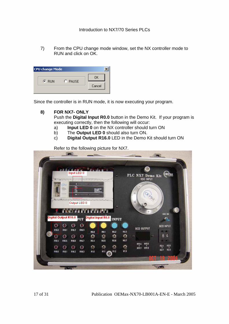
7) From the CPU change mode window, set the NX controller mode to
RUN and click on OK.
Since the controller is in RUN mode, it is now executing your program.
8) FOR NX7- ONLY Push the Digital Input R0.0 button in the Demo Kit. If your program is executing correctly, then the following will occur: a) Input LED 0 on the NX controller should turn ON b) The Output LED 0 should also turn ON. c) Digital Output R16.0 LED in the Demo Kit should turn ON Refer to the following picture for NX7.

Introduction to NX7/70 Series PLCs
18 of 31 Publication OEMax-NX70-LB001A-EN-E - March 2005
FOR NX70- ONLY Push the Digital Input R0.0 button in the Demo Kit. If your program is executing correctly, then the following will occur: d) Input LED 0 on the NX70-X16D input module should turn ON e) The Output LED 0 on the NX70-Y16R relay module should also
turn ON. f) Digital Output R2.0 LED in the Demo Kit should turn ON Refer to the following picture for NX70.
Introduction to NX7/70 Series PLCs
19 of 31 Publication OEMax-NX70-LB001A-EN-E - March 2005
You are doing real time control and it only took a few minutes. NX7/70 is great for small, low-cost applications!
NX7/70 has 2 Com Ports. Use COM1 for Programming and COM2 for Operator Interface, PLC Networking, etc.
Introduction to NX7/70 Series PLCs
20 of 31 Publication OEMax-NX70-LB001A-EN-E - March 2005
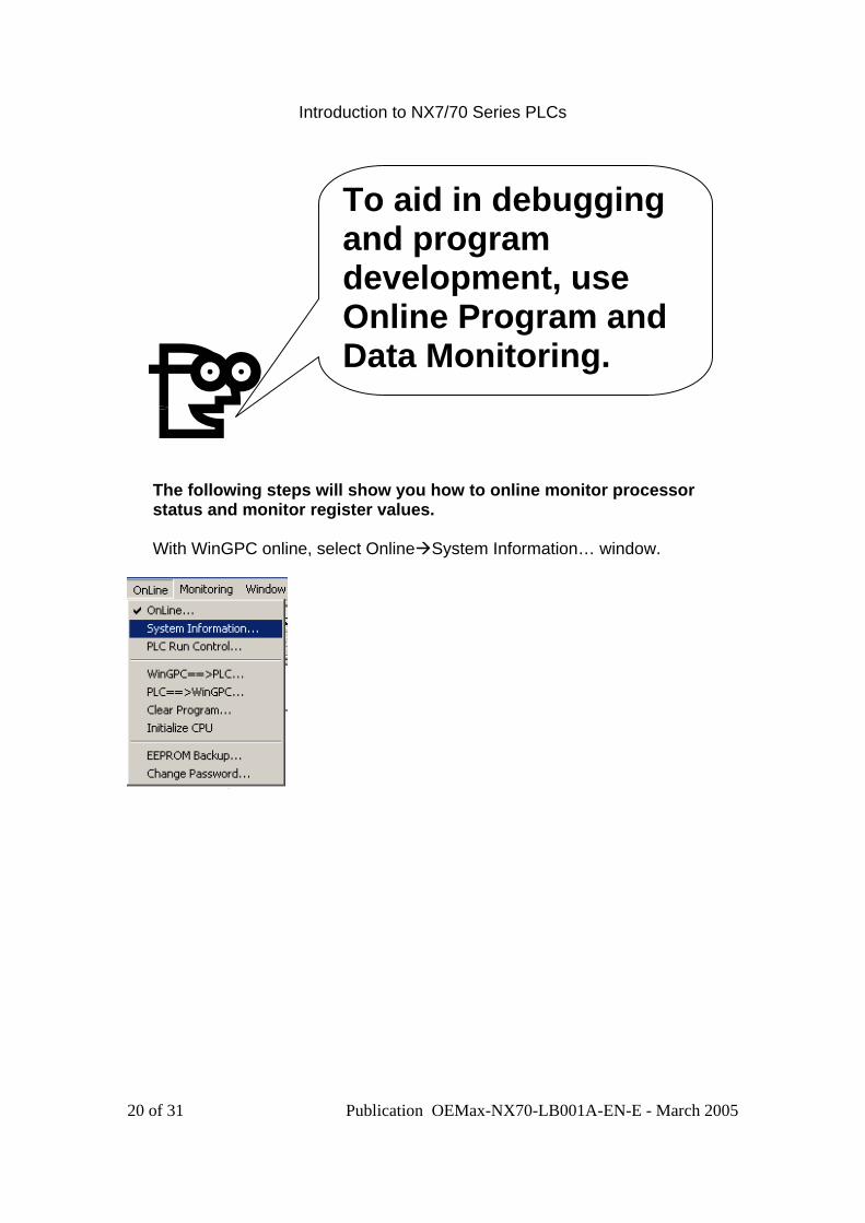
The following steps will show you how to online monitor processor status and monitor register values. With WinGPC online, select Online System Information… window.
To aid in debugging and program development, use Online Program and Data Monitoring.

Introduction to NX7/70 Series PLCs
21 of 31 Publication OEMax-NX70-LB001A-EN-E - March 2005
The System Information window looks like the following screen capture. From here you can obtain the PLC status and also bring up the Error Table window. For example: This window shows that the PLC’s Real Time Clock (RTC) date is “2004-10-11”. If it is incorrect, click on the “RTC date” button to update the date.
1) Click on Close to close the window. 2) From WinGPC, select Monitoring Ladder Monitoring to enable monitoring of the ladder program. Make sure there is a check mark next to “Ladder Monitoring” as show in the following picture.

Introduction to NX7/70 Series PLCs
22 of 31 Publication OEMax-NX70-LB001A-EN-E - March 2005
4) Refer back to the WinGPC ladder program. If you press the Digital Input button on the demo kit, you can now see the ladder rung animated as the input R000.00 and output R016.00 turns ON. Refer to the following picture.
3) From WinGPC, select Monitoring->Register Monitoring…

Introduction to NX7/70 Series PLCs
23 of 31 Publication OEMax-NX70-LB001A-EN-E - March 2005
The following window should appear. From this window, you can monitor register values and also modify register values.

Introduction to NX7/70 Series PLCs
24 of 31 Publication OEMax-NX70-LB001A-EN-E - March 2005
4) Press the Digital Input button R0.0 on the demo kit. You should see the Register Monitoring window reflect the state of R000.00 (input) and R016.00 (output) from your ladder program.
6) Click on the “X” to close the window.
The NX controller also has many other features such as forcing, histograms/time charts to make programming and debug easier.

Introduction to NX7/70 Series PLCs
25 of 31 Publication OEMax-NX70-LB001A-EN-E - March 2005
The following steps will show you how to save the program to flash eeprom.
1) With WinGPC online, select Online PLC Run Control…
2) In the CPU change Mode window, change the processor mode to “Pause” state and click on “OK”. The ladder program will stop execution and all outputs will be inactive. NOTE: Some PLCs use the term “Idle” or “Program” mode instead of “Pause”.
Backup your program to Flash EEPROM in case of battery failure.

Introduction to NX7/70 Series PLCs
26 of 31 Publication OEMax-NX70-LB001A-EN-E - March 2005
3) Select Online EEPROM Backup…
4) In the window click on “OK” to save the project to flash EEPROM.
A Backup Completed window should appear. Acknowledge by clicking on the OK button.
If an error occurs, check to make sure the processor is in Pause mode.

Introduction to NX7/70 Series PLCs
27 of 31 Publication OEMax-NX70-LB001A-EN-E - March 2005
NOTE: The NX controllers have 3 levels of backup protection. Saves … Length of Protection SRAM Battery Backup Program and Current Data Until battery dies Super Capacitor Program and Current Data 1-2 days Flash EEPROM Program Forever NOTE NX7 only: Register F13.01 is used to restore the saved program from flash to SRAM. Set bit F13.01 to 1 while in Pause mode to restore from flash to SRAM. Also restore from flash to SRAM will occur if there is a SRAM fault at powerup. NOTE NX70 only: DIP switch (bit 1 set to ON) on the bottom of the processor is used to restore the saved program from flash to SRAM after a power cycle.
The Flash EEPROM backup feature can recover your saved program without a battery and without the original user program. Extra insurance against future failures.

Introduction to NX7/70 Series PLCs
28 of 31 Publication OEMax-NX70-LB001A-EN-E - March 2005
END OF LAB

Introduction to NX7/70 Series PLCs
29 of 31 Publication OEMax-NX70-LB001A-EN-E - March 2005
Appendix A NX70 Demo Kit Configuration 1) First remove Processor from Chassis by loosening the screw at the top. Then press the release latch at the top and pull the top of the module out. The module will pivot at the bottom and then release. (Reverse the steps to reinsert the module.) Refer to section 4 of the following picture for the NX70 processor. All DIP switches at the top of the processor should be set to the OFF position. This sets COM1 to RS-232 9600baud.

Introduction to NX7/70 Series PLCs
30 of 31 Publication OEMax-NX70-LB001A-EN-E - March 2005
2) Check to make sure that the Program/Remote/Run switch is set to Remote (RMT). Refer to section 2 of the previous picture. NOTE: Remote Mode allows WinGPC to control the RUN/PROGRAM mode of the controller, instead of using this switch. 3) Check to make sure that the RS-232 serial cable is connected from the PC to the NX controller in the Demo Kit. 4) Check to make sure the Demo Kit is powered up.

Introduction to NX7/70 Series PLCs
31 of 31 Publication OEMax-NX70-LB001A-EN-E - March 2005
Appendix B NX7 Demo Kit Configuration 1) Check to make sure COM1 on the front of the controller is set for RS-232 (i.e. down). You must open up the door on the left side of the controller to see the switch.
Switch behind left side door
2) Check to make sure that the Program/Remote/Run switch is set to Remote (RMT). This switch is located behind the door on the right side of the controller.
Switch Behind Right Side Door
NOTE: Remote Mode allows WinGPC to control the RUN/PROGRAM mode of the controller, instead of using this switch. 3) Check to make sure that the RS-232 serial cable is connected from the PC to the NX controller in the Demo Kit. 4) Check to make sure the Demo Kit is powered up.