introduction to the wasp interface. watershed & water quality modeling technical support center...
TRANSCRIPT
Introduction to the WASP Introduction to the WASP InterfaceInterface
Watershed & Water Quality Modeling Technical Support CenterWatershed & Water Quality Modeling Technical Support Center
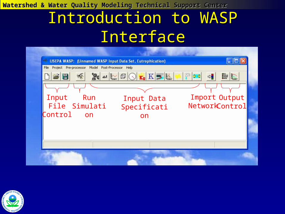
Introduction to WASP InterfaceIntroduction to WASP Interface
Input File Control
Run Simulation
Input Data Specification
Import Network
Output Control
Watershed & Water Quality Modeling Technical Support CenterWatershed & Water Quality Modeling Technical Support Center
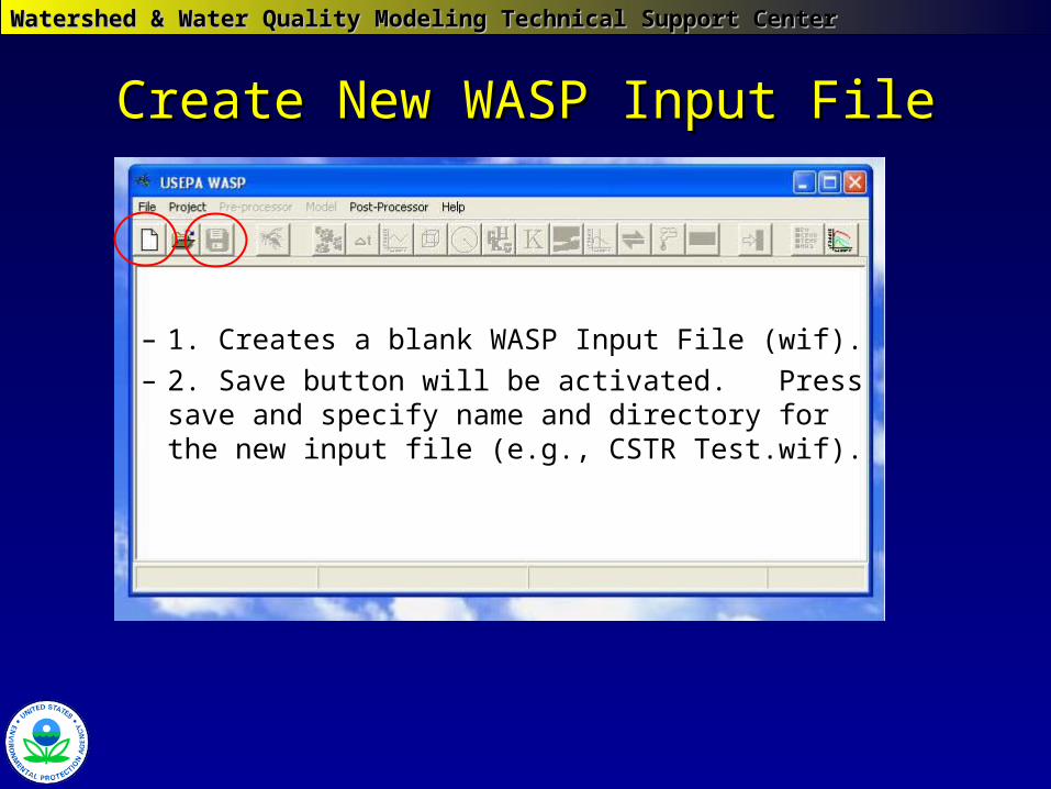
Create New WASP Input FileCreate New WASP Input File
– 1. Creates a blank WASP Input File (wif).– 2. Save button will be activated. Press
save and specify name and directory for the new input file (e.g., CSTR Test.wif).
Watershed & Water Quality Modeling Technical Support CenterWatershed & Water Quality Modeling Technical Support Center
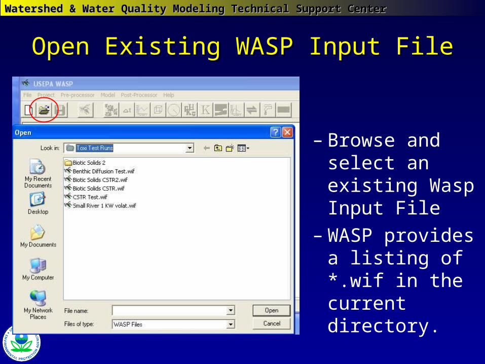
Open Existing WASP Input FileOpen Existing WASP Input File
– Browse and select an existing Wasp Input File
– WASP provides a listing of *.wif in the current directory.
Watershed & Water Quality Modeling Technical Support CenterWatershed & Water Quality Modeling Technical Support Center
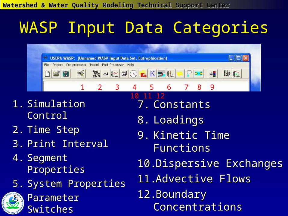
WASP Input Data CategoriesWASP Input Data Categories
1.1. Simulation ControlSimulation Control
2.2. Time StepTime Step
3.3. Print IntervalPrint Interval
4.4. Segment PropertiesSegment Properties
5.5. System PropertiesSystem Properties
6.6. Parameter SwitchesParameter Switches
7.7. ConstantsConstants
8.8. LoadingsLoadings
9.9. Kinetic Time FunctionsKinetic Time Functions
10.10. Dispersive ExchangesDispersive Exchanges
11.11. Advective FlowsAdvective Flows
12.12. Boundary ConcentrationsBoundary Concentrations
1 2 3 4 5 6 7 8 9 10 11 12
Watershed & Water Quality Modeling Technical Support CenterWatershed & Water Quality Modeling Technical Support Center
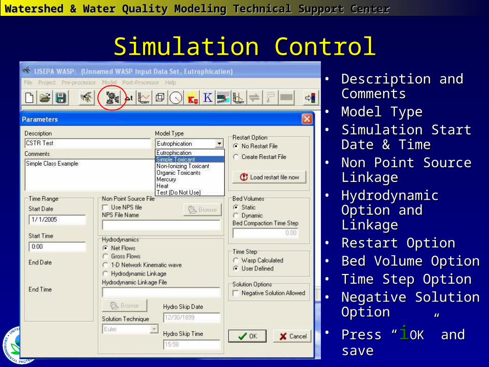
Simulation ControlSimulation Control• Description and Description and
CommentsComments• Model TypeModel Type• Simulation Start Date & Simulation Start Date &
TimeTime• Non Point Source Non Point Source
LinkageLinkage• Hydrodynamic Option Hydrodynamic Option
and Linkageand Linkage• Restart OptionRestart Option• Bed Volume OptionBed Volume Option• Time Step OptionTime Step Option• Negative Solution Negative Solution
OptionOption
• Press “Press “iiOKOK” and save” and save
Watershed & Water Quality Modeling Technical Support CenterWatershed & Water Quality Modeling Technical Support Center
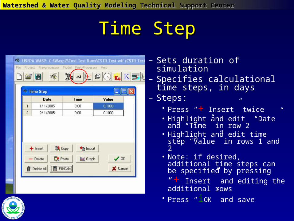
Time StepTime Step
– Sets duration of simulation– Specifies calculational time
steps, in days– Steps:
• Press “+ Insert” twice• Highlight and edit “Date” and
“Time” in row 2• Highlight and edit time step
“Value” in rows 1 and 2 • Note: if desired, additional time
steps can be specified by
pressing “+ Insert” and editing the additional rows
• Press “iOK” and save
Watershed & Water Quality Modeling Technical Support CenterWatershed & Water Quality Modeling Technical Support Center
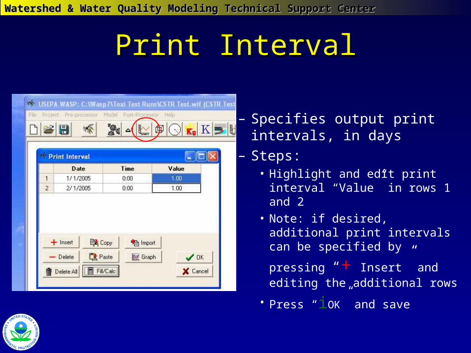
Print IntervalPrint Interval
– Specifies output print intervals, in days
– Steps:• Highlight and edit print interval
“Value” in rows 1 and 2 • Note: if desired, additional print
intervals can be specified by
pressing “+ Insert” and editing the additional rows
• Press “iOK” and save

Watershed & Water Quality Modeling Technical Support CenterWatershed & Water Quality Modeling Technical Support Center
Segment Properties - GeometrySegment Properties - Geometry
• Steps to specify simple network geometry:Steps to specify simple network geometry:• Press “+ Insert” to create segment rows• Highlight and edit Description, Volume, and Depth Multiplier for rows• Select Segment Type
• Press “iOK” and save
Watershed & Water Quality Modeling Technical Support CenterWatershed & Water Quality Modeling Technical Support Center
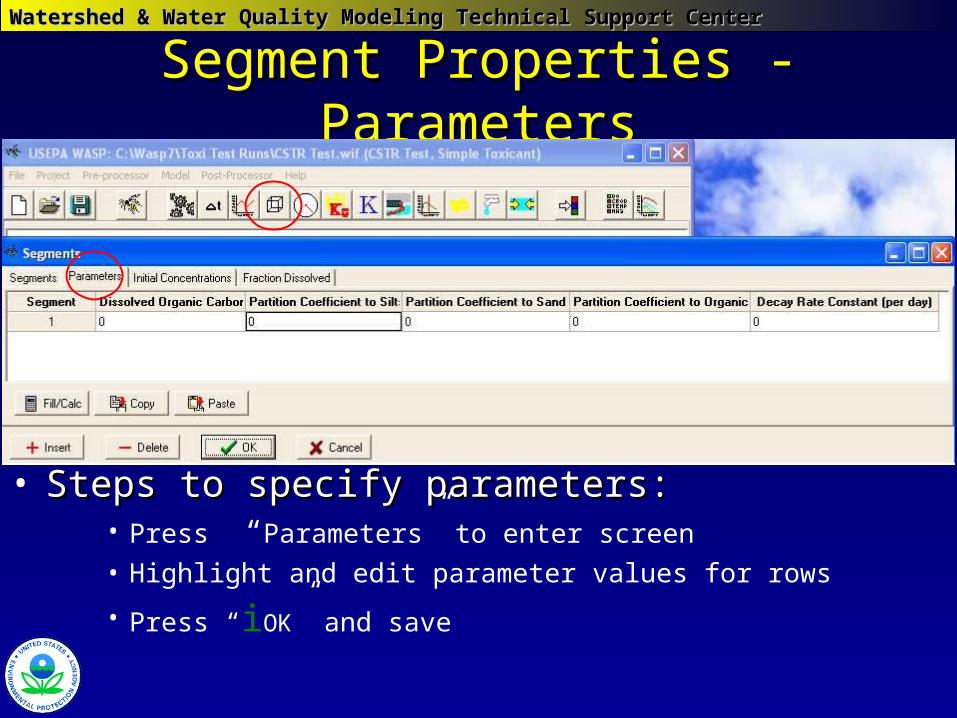
Segment Properties - ParametersSegment Properties - Parameters
• Steps to specify parameters:Steps to specify parameters:• Press “Parameters” to enter screen
• Highlight and edit parameter values for rows
• Press “iOK” and save
Watershed & Water Quality Modeling Technical Support CenterWatershed & Water Quality Modeling Technical Support Center
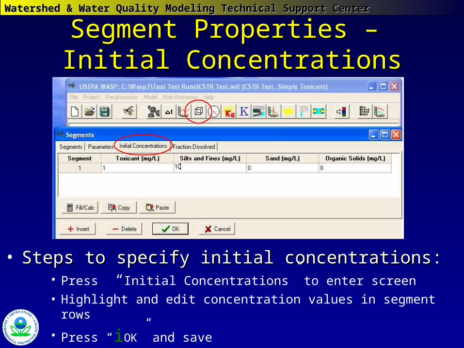
Segment Properties – Segment Properties – Initial ConcentrationsInitial Concentrations
• Steps to specify initial concentrations:Steps to specify initial concentrations:• Press “Initial Concentrations” to enter screen
• Highlight and edit concentration values in segment rows
• Press “iOK” and save
Watershed & Water Quality Modeling Technical Support CenterWatershed & Water Quality Modeling Technical Support Center
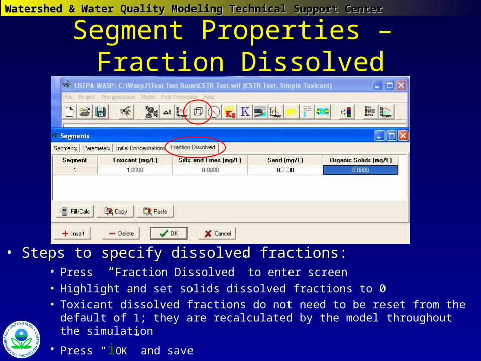
Segment Properties – Segment Properties – Fraction DissolvedFraction Dissolved
• Steps to specify dissolved fractions:Steps to specify dissolved fractions:• Press “Fraction Dissolved” to enter screen
• Highlight and set solids dissolved fractions to 0
• Toxicant dissolved fractions do not need to be reset from the default of 1; they are recalculated by the model throughout the simulation
• Press “iOK” and save
Watershed & Water Quality Modeling Technical Support CenterWatershed & Water Quality Modeling Technical Support Center
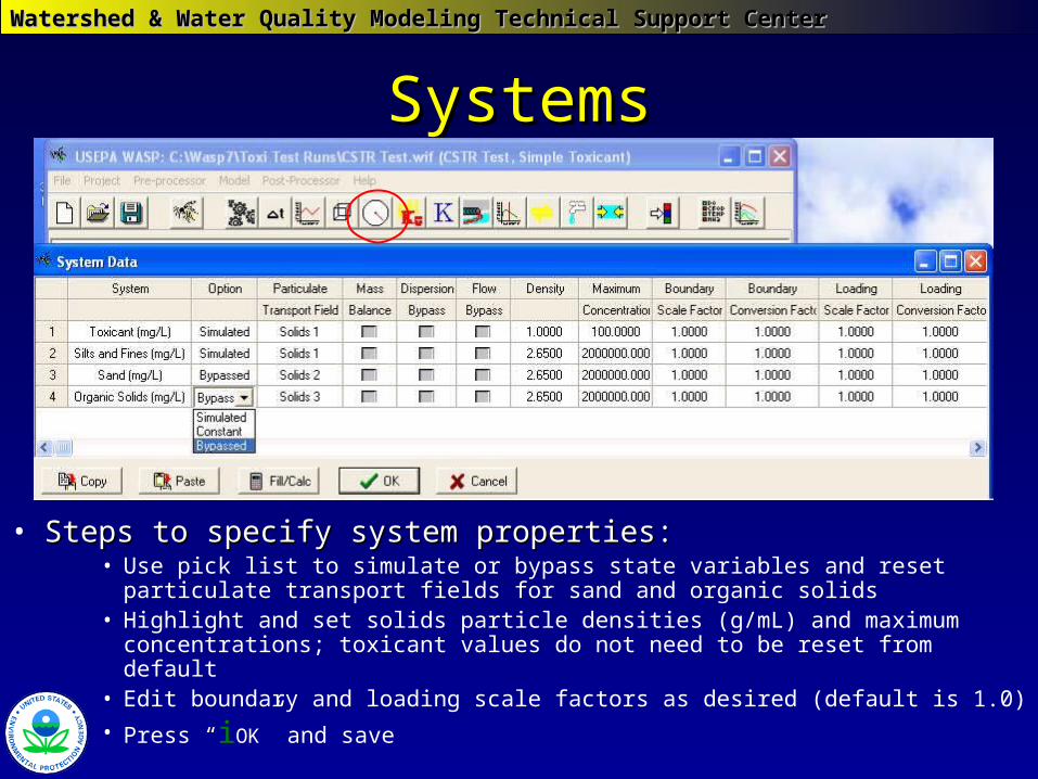
SystemsSystems
• Steps to specify system properties:Steps to specify system properties:• Use pick list to simulate or bypass state variables and reset particulate
transport fields for sand and organic solids• Highlight and set solids particle densities (g/mL) and maximum
concentrations; toxicant values do not need to be reset from default• Edit boundary and loading scale factors as desired (default is 1.0)
• Press “iOK” and save
Watershed & Water Quality Modeling Technical Support CenterWatershed & Water Quality Modeling Technical Support Center
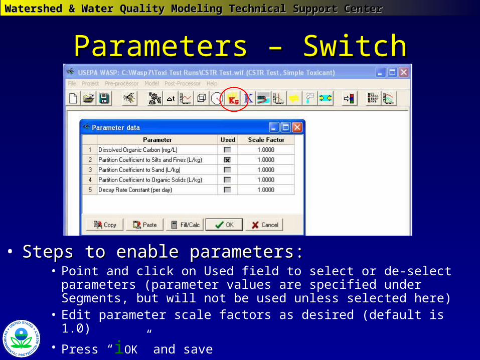
Parameters – SwitchParameters – Switch
• Steps to enable parameters:Steps to enable parameters:• Point and click on Used field to select or de-select parameters
(parameter values are specified under Segments, but will not be used unless selected here)
• Edit parameter scale factors as desired (default is 1.0)
• Press “iOK” and save
Watershed & Water Quality Modeling Technical Support CenterWatershed & Water Quality Modeling Technical Support Center
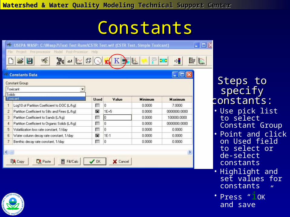
ConstantsConstants
Steps to specify Steps to specify constants:constants:• Use pick list to
select Constant Group
• Point and click on Used field to select or de-select constants
• Highlight and set values for constants
• Press “iOK” and save
Watershed & Water Quality Modeling Technical Support CenterWatershed & Water Quality Modeling Technical Support Center
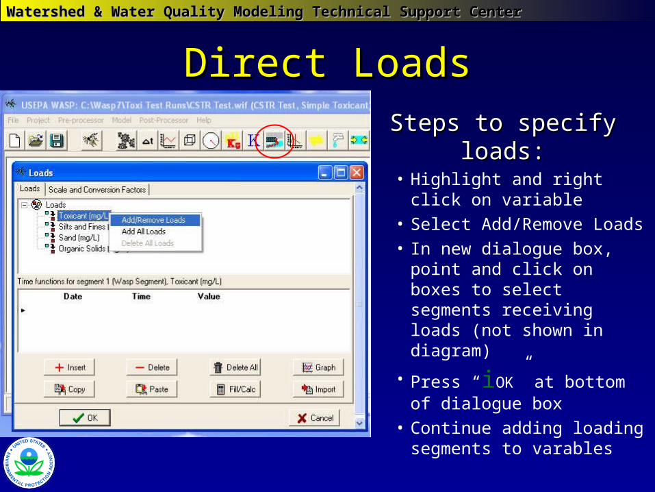
Direct LoadsDirect Loads
Steps to specify loads:Steps to specify loads:• Highlight and right click on
variable• Select Add/Remove Loads• In new dialogue box, point
and click on boxes to select segments receiving loads (not shown in diagram)
• Press “iOK” at bottom of dialogue box
• Continue adding loading segments to varables
Watershed & Water Quality Modeling Technical Support CenterWatershed & Water Quality Modeling Technical Support Center
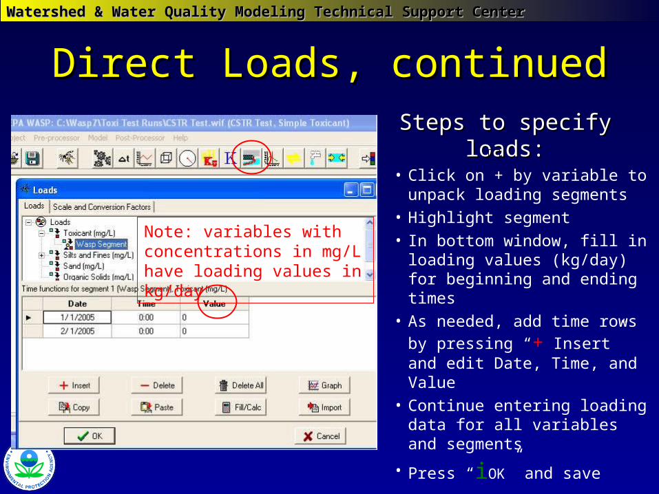
Direct Loads, continuedDirect Loads, continued
Steps to specify loads:Steps to specify loads:• Click on + by variable to
unpack loading segments • Highlight segment• In bottom window, fill in
loading values (kg/day) for beginning and ending times
• As needed, add time rows
by pressing “+ Insert” and edit Date, Time, and Value
• Continue entering loading data for all variables and segments
• Press “iOK” and save
Note: variables with concentrations in mg/L have loading values in kg/day
Watershed & Water Quality Modeling Technical Support CenterWatershed & Water Quality Modeling Technical Support Center
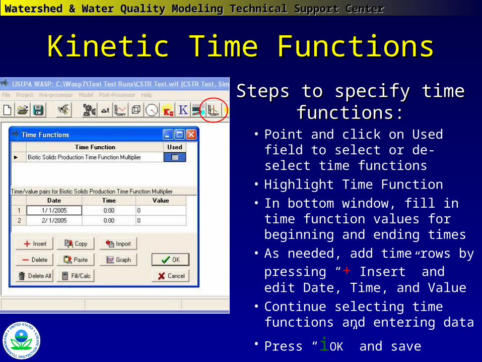
Kinetic Time FunctionsKinetic Time Functions
Steps to specify time Steps to specify time functions:functions:
• Point and click on Used field to select or de-select time functions
• Highlight Time Function• In bottom window, fill in time
function values for beginning and ending times
• As needed, add time rows by
pressing “+ Insert” and edit Date, Time, and Value
• Continue selecting time functions and entering data
• Press “iOK” and save
Watershed & Water Quality Modeling Technical Support CenterWatershed & Water Quality Modeling Technical Support Center
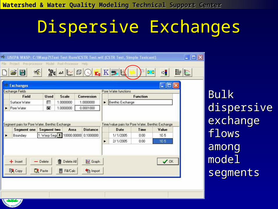
Dispersive ExchangesDispersive Exchanges
Bulk Bulk dispersive dispersive exchange exchange flows among flows among model model segmentssegments
Watershed & Water Quality Modeling Technical Support CenterWatershed & Water Quality Modeling Technical Support Center
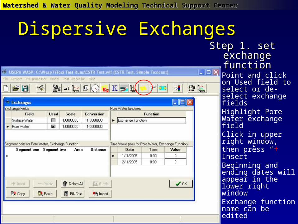
Dispersive ExchangesDispersive ExchangesStep 1. set Step 1. set
exchange functionexchange function• Point and click on
Used field to select or de-select exchange fields
• Highlight Pore Water exchange field
• Click in upper right window, then press “+ Insert”
• Beginning and ending dates will appear in the lower right window
• Exchange function name can be edited
Watershed & Water Quality Modeling Technical Support CenterWatershed & Water Quality Modeling Technical Support Center
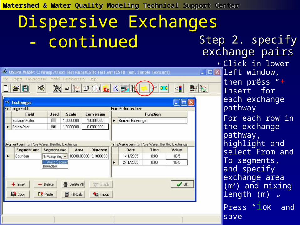
Dispersive ExchangesDispersive Exchanges - continued - continued Step 2. specify Step 2. specify
exchange pairsexchange pairs• Click in lower left
window, then press “+ Insert” for each exchange pathway
• For each row in the exchange pathway, highlight and select From and To segments, and specify exchange area (m2) and mixing length (m)
• Press “iOK” and save
Watershed & Water Quality Modeling Technical Support CenterWatershed & Water Quality Modeling Technical Support Center
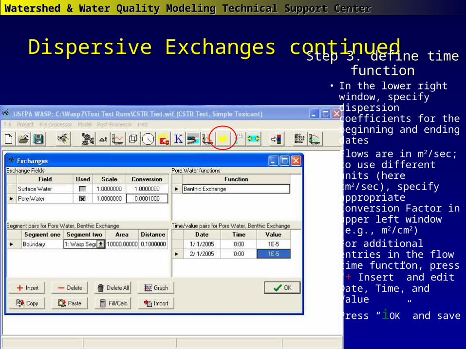
Dispersive Exchanges continuedDispersive Exchanges continuedStep 3. define time Step 3. define time
functionfunction• In the lower right
window, specify dispersion coefficients for the beginning and ending dates
• Flows are in m2/sec; to use different units (here cm2/sec), specify appropriate Conversion Factor in upper left window (e.g., m2/cm2)
• For additional entries in the flow time function, press “+ Insert” and edit Date, Time, and Value
• Press “iOK” and save
Watershed & Water Quality Modeling Technical Support CenterWatershed & Water Quality Modeling Technical Support Center
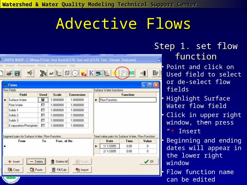
Advective FlowsAdvective Flows
Step 1. set flow Step 1. set flow functionfunction
• Point and click on Used field to select or de-select flow fields
• Highlight Surface Water flow field
• Click in upper right
window, then press “+ Insert”
• Beginning and ending dates will appear in the lower right window
• Flow function name can be edited
Watershed & Water Quality Modeling Technical Support CenterWatershed & Water Quality Modeling Technical Support Center
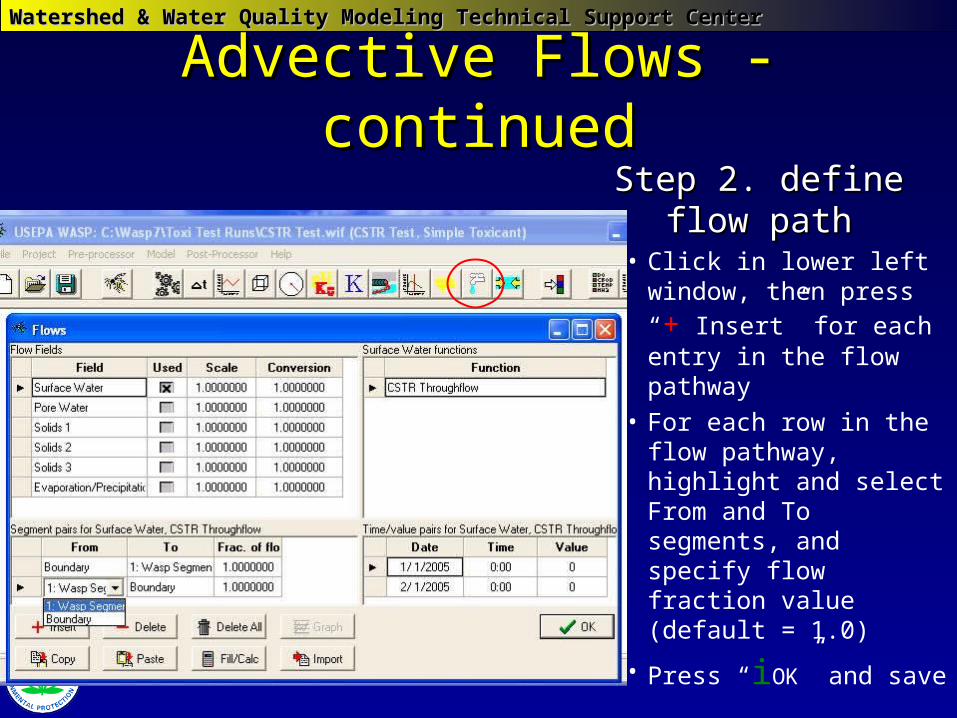
Advective Flows - continuedAdvective Flows - continued
Step 2. define flow Step 2. define flow pathpath
• Click in lower left
window, then press “+ Insert” for each entry in the flow pathway
• For each row in the flow pathway, highlight and select From and To segments, and specify flow fraction value (default = 1.0)
• Press “iOK” and save
Watershed & Water Quality Modeling Technical Support CenterWatershed & Water Quality Modeling Technical Support Center
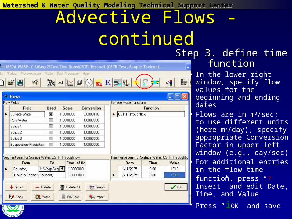
Advective Flows - continuedAdvective Flows - continuedStep 3. define time Step 3. define time
functionfunction• In the lower right
window, specify flow values for the beginning and ending dates
• Flows are in m3/sec; to use different units (here m3/day), specify appropriate Conversion Factor in upper left window (e.g., day/sec)
• For additional entries in the flow time function, press “+ Insert” and edit Date, Time, and Value
• Press “iOK” and save
Watershed & Water Quality Modeling Technical Support CenterWatershed & Water Quality Modeling Technical Support Center
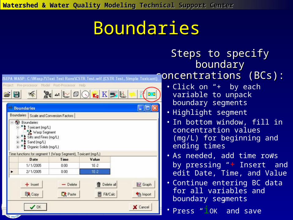
Steps to specify boundary Steps to specify boundary concentrations (BCs):concentrations (BCs):• Click on “+” by each variable to
unpack boundary segments • Highlight segment• In bottom window, fill in
concentration values (mg/L) for beginning and ending times
• As needed, add time rows by pressing “+ Insert” and edit Date, Time, and Value
• Continue entering BC data for all variables and boundary segments
• Press “iOK” and save
BoundariesBoundaries
Watershed & Water Quality Modeling Technical Support CenterWatershed & Water Quality Modeling Technical Support Center
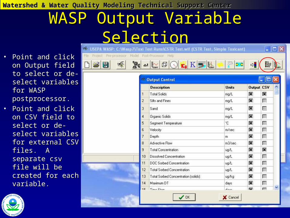
WASP Output Variable SelectionWASP Output Variable Selection
• Point and click on Point and click on Output field to Output field to select or de-select or de-select variables select variables for WASP for WASP postprocessor.postprocessor.
• Point and click on Point and click on CSV field to CSV field to select or de-select or de-select variables select variables for external CSV for external CSV files. A separate files. A separate csv file will be csv file will be created for each created for each variable.variable.
Watershed & Water Quality Modeling Technical Support CenterWatershed & Water Quality Modeling Technical Support Center
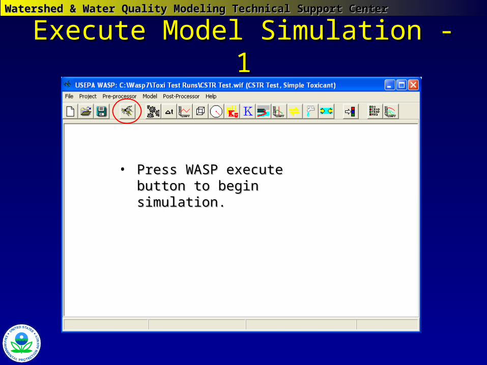
Execute Model Simulation -1Execute Model Simulation -1
• Press WASP execute button to Press WASP execute button to begin simulation.begin simulation.
Watershed & Water Quality Modeling Technical Support CenterWatershed & Water Quality Modeling Technical Support Center
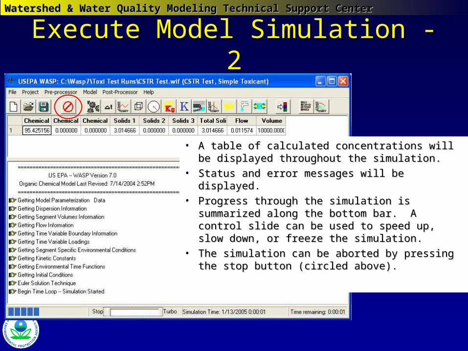
Execute Model Simulation - 2Execute Model Simulation - 2
• A table of calculated concentrations will be A table of calculated concentrations will be displayed throughout the simulation.displayed throughout the simulation.
• Status and error messages will be displayed.Status and error messages will be displayed.• Progress through the simulation is Progress through the simulation is
summarized along the bottom bar. A control summarized along the bottom bar. A control slide can be used to speed up, slow down, or slide can be used to speed up, slow down, or freeze the simulation.freeze the simulation.
• The simulation can be aborted by pressing The simulation can be aborted by pressing the stop button (circled above).the stop button (circled above).
Watershed & Water Quality Modeling Technical Support CenterWatershed & Water Quality Modeling Technical Support Center
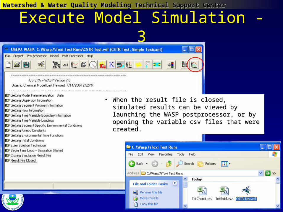
Execute Model Simulation - 3Execute Model Simulation - 3
• When the result file is closed, simulated When the result file is closed, simulated results can be viewed by launching the results can be viewed by launching the WASP postprocessor, or by opening the WASP postprocessor, or by opening the variable csv files that were created.variable csv files that were created.
Watershed & Water Quality Modeling Technical Support CenterWatershed & Water Quality Modeling Technical Support Center
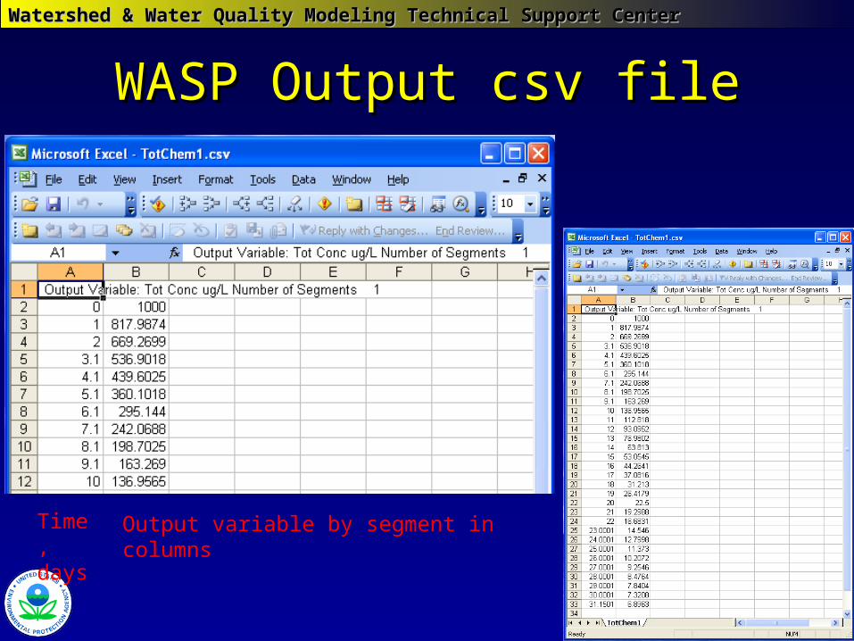
WASP Output csv fileWASP Output csv file
Time, days
Output variable by segment in columns
Watershed & Water Quality Modeling Technical Support CenterWatershed & Water Quality Modeling Technical Support Center
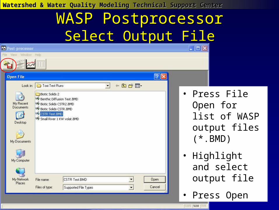
WASP PostprocessorWASP PostprocessorSelect Output FileSelect Output File
• Press File Open for list of WASP output files (*.BMD)
• Highlight and select output file
• Press Open
Watershed & Water Quality Modeling Technical Support CenterWatershed & Water Quality Modeling Technical Support Center
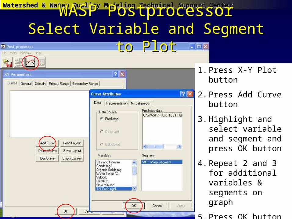
1. Press X-Y Plot button
2. Press Add Curve button
3. Highlight and select variable and segment and press OK button
4. Repeat 2 and 3 for additional variables & segments on graph
5. Press OK button to view graph
WASP PostprocessorWASP PostprocessorSelect Variable and Segment to PlotSelect Variable and Segment to Plot
Watershed & Water Quality Modeling Technical Support CenterWatershed & Water Quality Modeling Technical Support Center
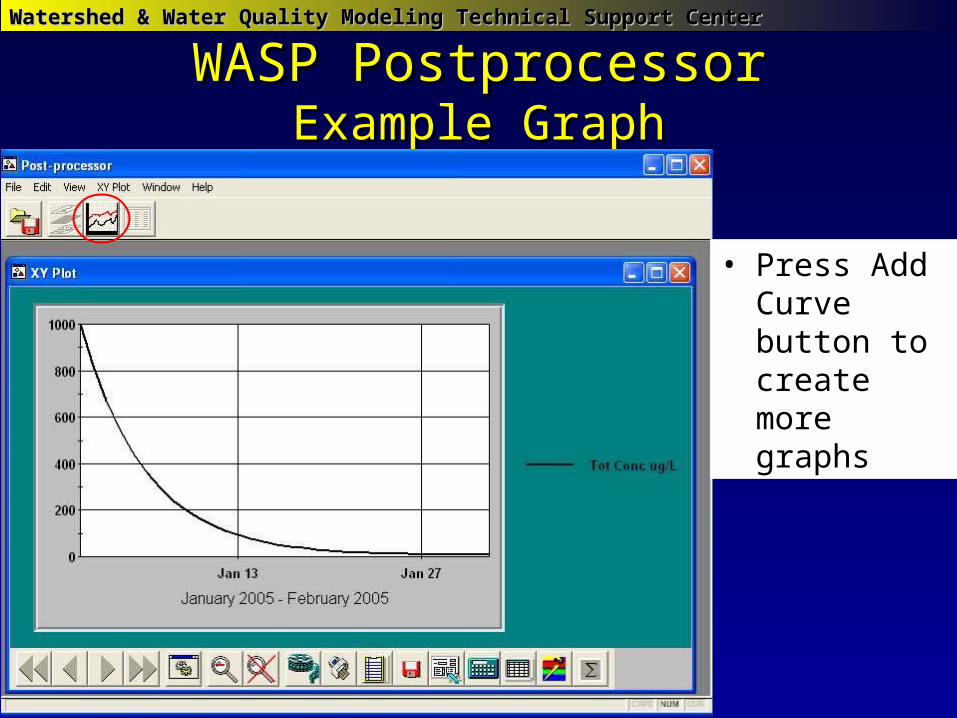
WASP PostprocessorWASP PostprocessorExample GraphExample Graph
• Press Add Curve button to create more graphs
Watershed & Water Quality Modeling Technical Support CenterWatershed & Water Quality Modeling Technical Support Center
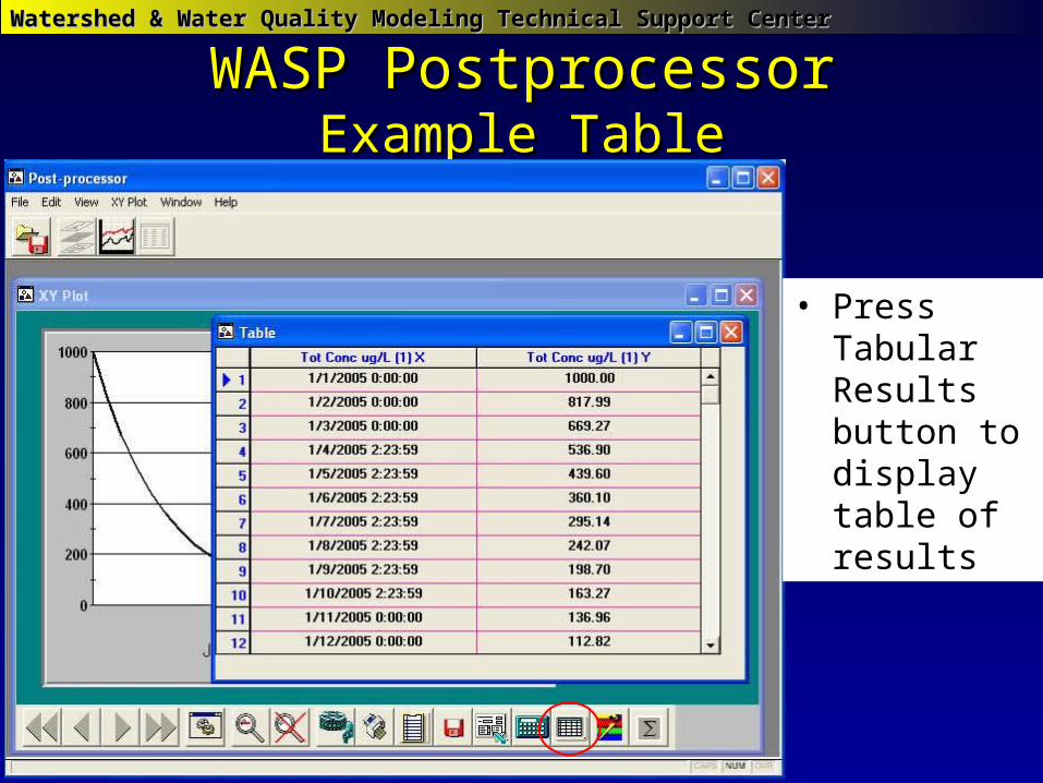
WASP PostprocessorWASP PostprocessorExample TableExample Table
• Press Tabular Results button to display table of results