investigation into the double-layer barrel vault …irf/proceedings_irf2018/data/papers/7236.pdf ·...
TRANSCRIPT
Proceedings IRF2018: 6th International Conference Integrity-Reliability-Failure
Lisbon/Portugal 22-26 July 2018. Editors J.F. Silva Gomes and S.A. Meguid
Publ. INEGI/FEUP (2018); ISBN: 978-989-20-8313-1
-607-
PAPER REF: 7236
INVESTIGATION INTO THE DOUBLE-LAYER BARREL VAULT SPACE STRUCTURE RESISTANCE TO PROGRESSIVE COLLAPSE Karim Abedi(*), Shahram Roshandel Kolachahi
Sahand University of Technology, Civil Engineering Department,Tabriz, Iran (*)
Email: [email protected] ABSTRACT
Space structures are widely used to cover areas with no or few intermediate columns. These structures possess important features such as light weight, elegant appearance, fast production as well as ease of erection. Beside all these advantageous, space structures are prone to the progressive collapse, which more often occurs due to failure of compression members. In the present study, the “Alternate Path Method” has been used for the evaluation of progressive collapse occurrence in the double-layer barrel vault space structures. At first, the critical members, which their bucking causes the total collapse of the structure, have been selected. Then, geometric-material nonlinear static and dynamic alternate path analyses have been carried out considering the removal of critical members. When the progressive collapse occurs, the Force Limiting Devices were used in the critical members in order to prevent the occurrence of progressive collapse in these structures. Force limiting devices are used to alter space structure compression members’ brittle post-buckling behavior to elastic-perfectly plastic post buckling behavior.
Keywords: space structures, double-layer barrel vault, stability, progressive collapse, alternative path method, Force limiting device.
INTRODUCTION
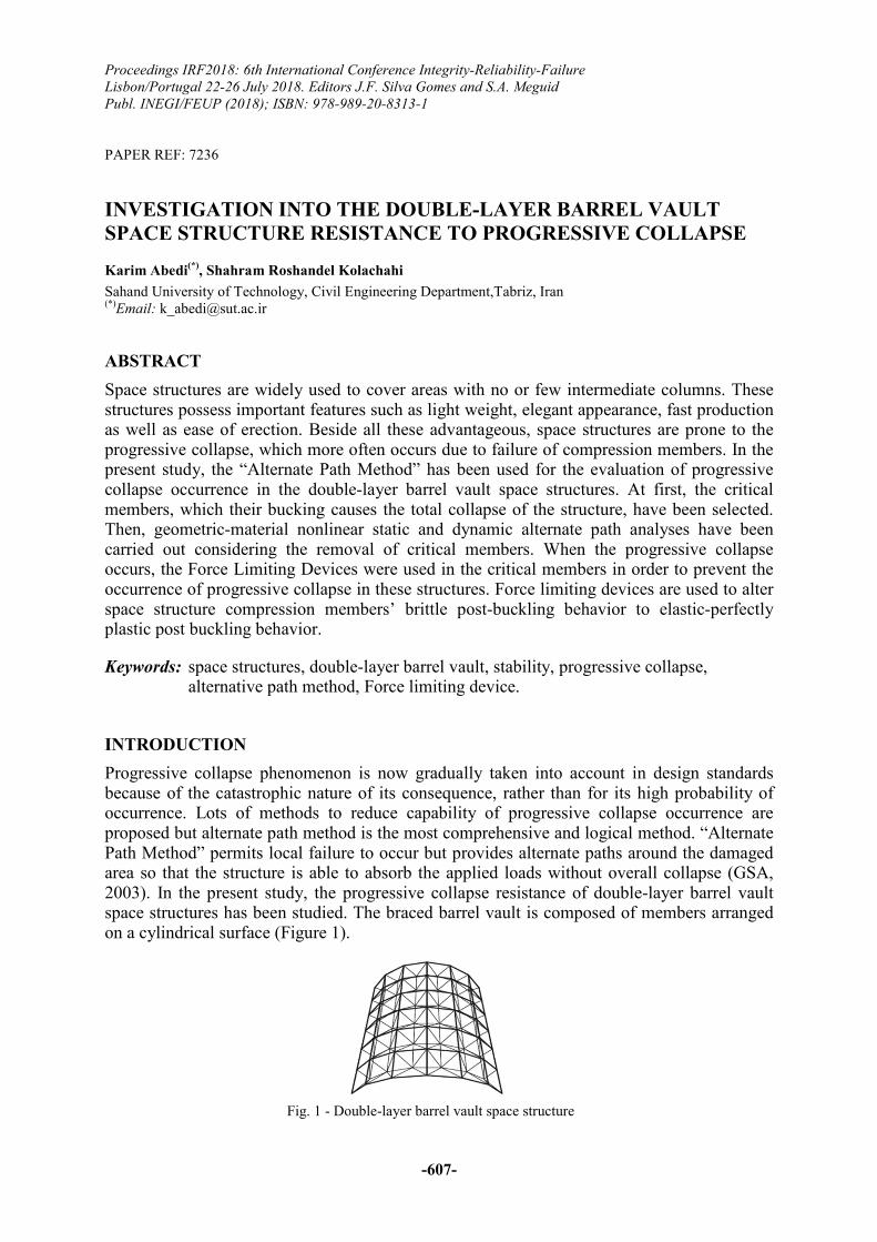
Progressive collapse phenomenon is now gradually taken into account in design standards because of the catastrophic nature of its consequence, rather than for its high probability of occurrence. Lots of methods to reduce capability of progressive collapse occurrence are proposed but alternate path method is the most comprehensive and logical method. “Alternate Path Method” permits local failure to occur but provides alternate paths around the damaged area so that the structure is able to absorb the applied loads without overall collapse (GSA, 2003). In the present study, the progressive collapse resistance of double-layer barrel vault space structures has been studied. The braced barrel vault is composed of members arranged on a cylindrical surface (Figure 1).
Fig. 1 - Double-layer barrel vault space structure

Topic-I: Civil and Structural Engineering Applications
-608-
The basic curve is a circular segment; occasionally, a parabola, ellipse or funicular line may also be used.
In this study, at first the double-layer barrel vault space structures have been configured using the FORMIAN software. Then, these structures are designed using the SAP2000 v18.1.1 according to the AISC360-2010. All of the nonlinear static and dynamic alternate path analyses have been undertaken using ABAQUS, which is a general-purpose finite element program designed specifically for advanced structural analysis. In this study, to trace the equilibrium paths through limit points into the post-critical range, the ‘Arc-Length Method’ has been used. Also, the dynamic alternate path method is presented to apply the dynamic effects of initial local failure. This method can be used to evaluate realistic collapse behavior of the structure and to investigate the vulnerability of the structure to progressive collapse phenomenon. Finally, when the progressive collapse is occurring, the critical compression members are equipped with force limiting devices in order to prevent the occurrence of progressive collapse in these structures.
DETERMINATION OF THE COMPRESSIVE MEMBER BEHAVIOR
In this study, the double-layer barrel vault space structures with 80×120 m dimensions and the mostly used height to span ratios (h/s) of 0.1, 0.2 and 0.3 have been considered (Figure 2).
h/s=0.3 h/s=0.2 h/s=0.1
Fig. 2 - Barrel vault models with three different height to span ratios
Most of the double layer space structures are constructed with pin connections. A nonlinear static analysis has been carried out for obtaining the axial stress-axial strain behavior of compressive members. In order to achieve the dominant buckling mode in member, according to the Figure 3 an initial curvature with maximum lateral deflection amount of 0.001L is applied to the middle of element (Shekastehband, 2014). Materially and geometrically nonlinearities were considered for nonlinear analysis (Sheidaii, 2003). For determining load-displacement behavior after the limit point, the modified Riks method is used which is based on the Arc-length method.
Fig. 3 - The initial curvature of the compression members

Proceedings IRF2018: 6th International Conference Integrity-Reliability-Failure
-609-
As an example, the ideal axial stress-axial strain behaviors in tension and compression of the pipe members with length of 3 m, used in all three model, have been shown in Figure 4.
(a) (b)
(c) (d) Fig. 4 - The ideal axial stress-axial strain behaviors in tension and compression of the pipe members
with length of 3 m
DETERMINATION OF THE CRITICAL MEMBERS
In order to find the critical members of the models, which their bucking causes the total collapse of the structure, at first a nonlinear collapse analysis has been carried out. It is obvious that the removal of these members leads to considerable redistribution of the forces in the remaining structure. In this stage, 12 critical members have been considered for each model. As an example, the critical members of the structure with the rise to span ratio (h/s) of 0.3 under the symmetric snow load are depicted in Figure 5. All of the critical members have situated in the bottom layers. NONLINEAR ALTERNATE PATH ANALYSES
At first, the critical members, which their bucking causes the total collapse of the structure, have been selected. In each analysis, only one member was removed from the overall barrel vault model, and the structures were analyzed to determine the effect. Member loss could be realized either gradually over part of loading history on the model, or suddenly at any load level (Shekastehband, 2011). Then, geometric and material nonlinear static alternate path analyses have been carried out considering the gradual removal of critical members. Table 1 gives the safety factor values obtained through the nonlinear static path analysis for all models under different loading conditions. It is obvious that all of the obtained safety factors are greater than 1. As given in Table 1, safety factor values increase by increasing h/s ratio at the

Topic-I: Civil and Structural Engineering Applications
-610-
same load pattern. Also through nonlinear static analysis of alternative path, it can be concluded that the possibility of the occurrence of the progressive collapse for the models with the safety factor value of near 1 is high due to the dynamic effects of member removal.
Fig. 5 - The critical members of the barrel vault model with the rise to span ratio (h/s) of 0.3
Table 1 - The safety factor values obtained through the nonlinear path method for all models under
different loading conditions
The height to span ratio of structure
h/s=0.1 h/s=0.2 h/s=0.3
Symmetric Asymmetric Symmetric Asymmetric Symmetric Asymmetric
Perfect 1.71 1.99 1.89 2.03 2.41 2.73
Removal of member 1 1.1 1.4 1.37 1.76 1.57 1.67
Removal of member 2 1.11 1.46 1.33 1.79 1.58 1.7
Removal of member 3 1.15 1.48 1.37 1.76 1.64 1.69
Removal of member 4 1.15 1.48 1.36 1.81 1.62 1.71
Removal of member 5 1.44 1.59 1.72 2.0 1.86 1.77
Removal of member 6 1.39 1.63 1.7 2.0 1.92 1.76
Removal of member 7 1.41 1.6 1.67 1.98 1.86 1.81
Removal of member 8 1.41 1.63 1.68 1.98 1.86 1.82
Removal of member 9 1.54 1.53 1.75 1.93 1.84 1.75
Removal of member 10 1.56 1.59 1.74 2.01 1.84 1.79
Removal of member 11 1.56 1.58 1.76 2.01 1.84 1.77
Removal of member 12 1.6 1.58 1.74 2.0 1.82 1.78
Proceedings IRF2018: 6th International Conference Integrity-Reliability-Failure
-611-
Therefore, in the following, nonlinear dynamic analyses is carried out. For this purpose, an eigenvalue frequency analysis is taken for determining input values of the dynamic analysis. For determination of the damping matrix, the “Rayleigh damping method” is used. This is achieved by introducing two factors αm and βs, which are constants to be determined from two given damping ratios that correspond to two unequal frequencies of vibration. The factor αm defines the mass proportional damping, and the factor βs expresses the stiffness proportional damping. Therefore, the damping matrix C can be defined as:
C= αm.M + βs.K (3)
where M is the mass matrix and K is the stiffness matrix. To find the factors αm and βs, the first five natural frequencies of the structure are obtained by an Eigen-value frequency analysis. Because, higher modes with high frequencies require a relatively large damping ratio, it is assumed that the first and fifth modes requires 1.5 percent and 2.5 percent, respectively, that is, ξ1=1.5% and ξ5=2.5%. The factors αm and βs can be determined using the following expressions:
αm=2 ω1.ω5.(ξ1. ω5- ξ5. ω1)/( ω52- ω1
2) (4)
βs =2(ξ5. ω5- ξ1. ω1)/( ω52- ω1
2) (5)
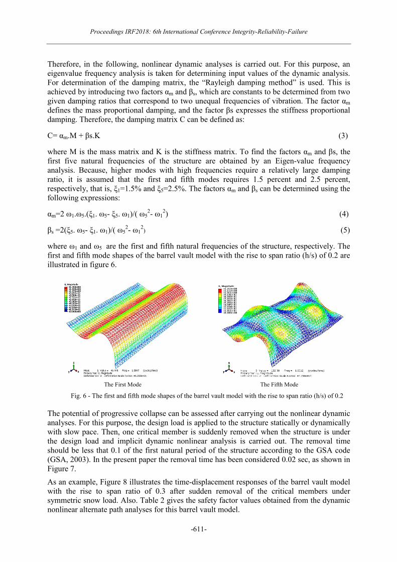
where ω1 and ω5 are the first and fifth natural frequencies of the structure, respectively. The first and fifth mode shapes of the barrel vault model with the rise to span ratio (h/s) of 0.2 are illustrated in figure 6.
The First Mode The Fifth Mode
Fig. 6 - The first and fifth mode shapes of the barrel vault model with the rise to span ratio (h/s) of 0.2
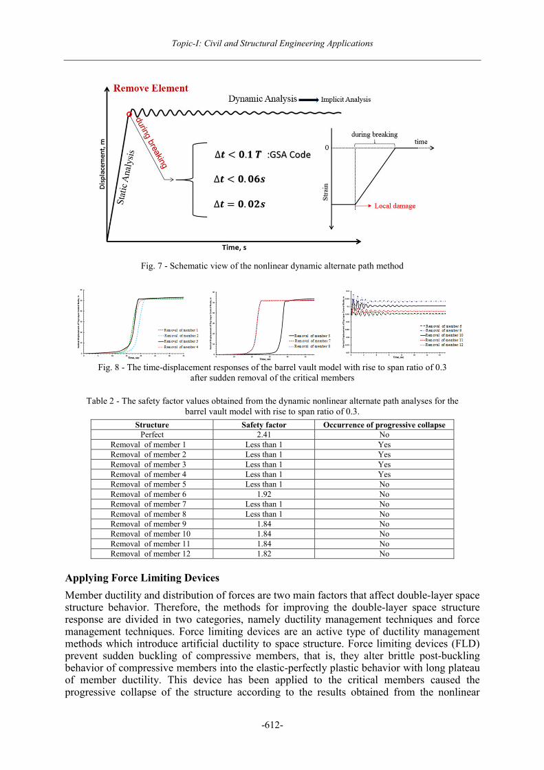
The potential of progressive collapse can be assessed after carrying out the nonlinear dynamic analyses. For this purpose, the design load is applied to the structure statically or dynamically with slow pace. Then, one critical member is suddenly removed when the structure is under the design load and implicit dynamic nonlinear analysis is carried out. The removal time should be less that 0.1 of the first natural period of the structure according to the GSA code (GSA, 2003). In the present paper the removal time has been considered 0.02 sec, as shown in Figure 7.
As an example, Figure 8 illustrates the time-displacement responses of the barrel vault model with the rise to span ratio of 0.3 after sudden removal of the critical members under symmetric snow load. Also. Table 2 gives the safety factor values obtained from the dynamic nonlinear alternate path analyses for this barrel vault model.
Topic-I: Civil and Structural Engineering Applications
-612-
Fig. 7 - Schematic view of the nonlinear dynamic alternate path method
Fig. 8 - The time-displacement responses of the barrel vault model with rise to span ratio of 0.3
after sudden removal of the critical members
Table 2 - The safety factor values obtained from the dynamic nonlinear alternate path analyses for the barrel vault model with rise to span ratio of 0.3.
Structure Safety factor Occurrence of progressive collapse Perfect 2.41 No
Removal of member 1 Less than 1 Yes Removal of member 2 Less than 1 Yes Removal of member 3 Less than 1 Yes Removal of member 4 Less than 1 Yes Removal of member 5 Less than 1 No Removal of member 6 1.92 No Removal of member 7 Less than 1 No Removal of member 8 Less than 1 No Removal of member 9 1.84 No Removal of member 10 1.84 No Removal of member 11 1.84 No Removal of member 12 1.82 No
Applying Force Limiting Devices
Member ductility and distribution of forces are two main factors that affect double-layer space structure behavior. Therefore, the methods for improving the double-layer space structure response are divided in two categories, namely ductility management techniques and force management techniques. Force limiting devices are an active type of ductility management methods which introduce artificial ductility to space structure. Force limiting devices (FLD) prevent sudden buckling of compressive members, that is, they alter brittle post-buckling behavior of compressive members into the elastic-perfectly plastic behavior with long plateau of member ductility. This device has been applied to the critical members caused the progressive collapse of the structure according to the results obtained from the nonlinear
Proceedings IRF2018: 6th International Conference Integrity-Reliability-Failure
-613-
dynamic alternate path analyses. The FLD has been activated in the critical compressive members when the axial load is reached to the 90% of its buckling load obtained from the nonlinear collapse analyses explained in Section 3, as shown in Figure 9.
Fig. 9 - The behavior of the critical members with and without FLD
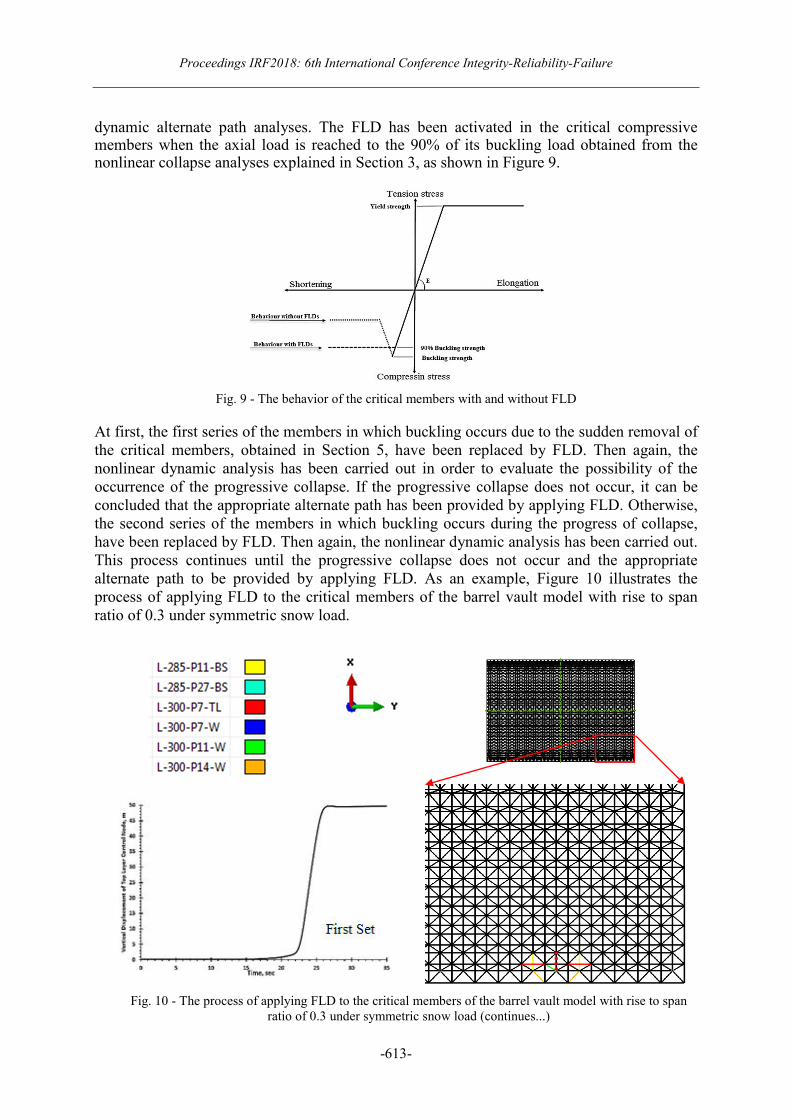
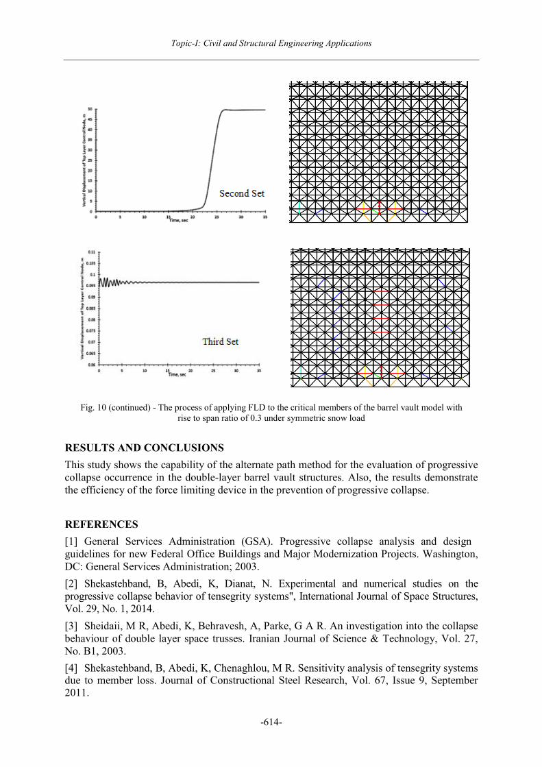
At first, the first series of the members in which buckling occurs due to the sudden removal of the critical members, obtained in Section 5, have been replaced by FLD. Then again, the nonlinear dynamic analysis has been carried out in order to evaluate the possibility of the occurrence of the progressive collapse. If the progressive collapse does not occur, it can be concluded that the appropriate alternate path has been provided by applying FLD. Otherwise, the second series of the members in which buckling occurs during the progress of collapse, have been replaced by FLD. Then again, the nonlinear dynamic analysis has been carried out. This process continues until the progressive collapse does not occur and the appropriate alternate path to be provided by applying FLD. As an example, Figure 10 illustrates the process of applying FLD to the critical members of the barrel vault model with rise to span ratio of 0.3 under symmetric snow load.
Fig. 10 - The process of applying FLD to the critical members of the barrel vault model with rise to span ratio of 0.3 under symmetric snow load (continues...)
Topic-I: Civil and Structural Engineering Applications
-614-
Fig. 10 (continued) - The process of applying FLD to the critical members of the barrel vault model with rise to span ratio of 0.3 under symmetric snow load
RESULTS AND CONCLUSIONS
This study shows the capability of the alternate path method for the evaluation of progressive collapse occurrence in the double-layer barrel vault structures. Also, the results demonstrate the efficiency of the force limiting device in the prevention of progressive collapse.
REFERENCES
[1] General Services Administration (GSA). Progressive collapse analysis and design guidelines for new Federal Office Buildings and Major Modernization Projects. Washington, DC: General Services Administration; 2003.
[2] Shekastehband, B, Abedi, K, Dianat, N. Experimental and numerical studies on the progressive collapse behavior of tensegrity systems", International Journal of Space Structures, Vol. 29, No. 1, 2014.
[3] Sheidaii, M R, Abedi, K, Behravesh, A, Parke, G A R. An investigation into the collapse behaviour of double layer space trusses. Iranian Journal of Science & Technology, Vol. 27, No. B1, 2003.
[4] Shekastehband, B, Abedi, K, Chenaghlou, M R. Sensitivity analysis of tensegrity systems due to member loss. Journal of Constructional Steel Research, Vol. 67, Issue 9, September 2011.