issue 6 summer 2007
TRANSCRIPT
Society of Oxford University Engineers
Summer 2007 Issue 6
SOUE News
Welcome to the sixth issue of SOUE News The Department of Engineering Science is about to celebrate its Centenary (1908–2008). We expect to treat this at some length next year; in the meantime our middle pages contain the programme of events the Department has organised. It starts with our Jenkin Day on 15 September, and a leaflet about that is enclosed too.
SOUE News is a bit bigger this year, not only because of the Centenary, but also because the Post Office has changed its charges, and we can now post a 100 g package (instead of 60 g) with a standard second-class stamp.
Among numerous other items, we have two articles by former undergraduates, a practice we are very keen to promote. Peter Meanley graduated from Wadham in 1959, and has had a civil engineering career much devoted to dry docks. He was moved by long experience of corrosion problems to ask what undergraduates were taught about it these days. On hearing, to his amazement, that "we don't do corrosion" in the syllabus for civil engineers (or for anyone else apparently), he wrote for us the article on p. 5. Read it and be warned!
Andy Pyle went down 40 years after Peter, and has been working in the nuclear power industry. Nuclear power has been rather out of favour in this country (unlike France) for about 20 years now, but the prospect of global warming is making it likely that more such stations will soon be built. This surely is something that we should all have informed views about. Andy looks at the history and reviews the future possibilities.
Andy's title is "A nuclear renaissance?", and renaissance seems to be in vogue, since last year's Jenkin Lecture, by Professor Rod Smith, was entitled "Railways: the technical challenges of their renaissance". It was very well received by the audience, and a report on it is on p. 27.
This year's Lubbock Lecture was by Sir Martin Wood, founder of Oxford Instruments, and more recently a great supporter of scientific education and industry in Oxfordshire. A report on his lecture is included, but to get the real flavour and humour of it, you are strongly recommended to view the video on the Department's website (www.eng.ox.ac.uk/events).
Cryogenics has long been one of the Department's research fields, and highly relevant to Oxford Instruments, so one of the other two lectures on Lubbock Day, which we have included here, was by Paul Bailey, describing the refrigerators and associated compressors that they have developed over the years.
And there are the usual regular items, and obituaries of four people who were on the academic staff at various times, and have died during the year: David Dew-Hughes, Gareth Roberts, Herby Sixsmith and Les Woods.
SOUE News Page 2
of University life nowadays. In common with all other UK Universities we are currently participating in a national survey of academic research — the 2008 Research Assessment Exercise. The University's research activity has to be written up and explained, and a vast array of data presented on people, income and outputs covering all the years since the last audit in 2001. The result will determine our funding position for some years to come, so has to be taken seriously. In February 2007 a 17-person team visited the Department to examine our teaching programme. The process is not yet finalised but we expect to obtain Accreditation by all the relevant Engineering Institutions.
Awards
Undergraduate Thomas Makin (Wadham) was selected as AMEC Best Civil Engineering Student of the Year at the national SET awards in October 2006 for his work on Timber Gridshell Structures. This follows his joint first prize in the Institution of Structural Engineers' Model Analysis Awards and second prize in the TRADA Student Timber Engineering Project. At the December SET for Britain event at the
Richard Darton
Introduction
Although the Department is now one hundred years old, it just seems to get more lively! The pace of change is astonishing, but then the opportunities are also tremendous. Highlights of the past year are described in this brief report, but other news about us can be found on our vast ly improved websi te (www.eng.ox.ac.uk — comments to [email protected] please, not to me!).
The course review is progressing well, though one is sometimes reminded that "changing a c u r r i c u l u m i s l i k e m o v i n g a graveyard" (according to Woodrow Wilson, onetime President of Princeton, and the USA). The new scheme will introduce second year examinations, and split third and fourth year papers into smaller (50%) units to avoid duplication and give students more choice; it will also improve the way we teach transferable skills. Undergraduates starting in Michaelmas 2008 will be the first to experience the new scheme.
Reviews and audits are an established feature
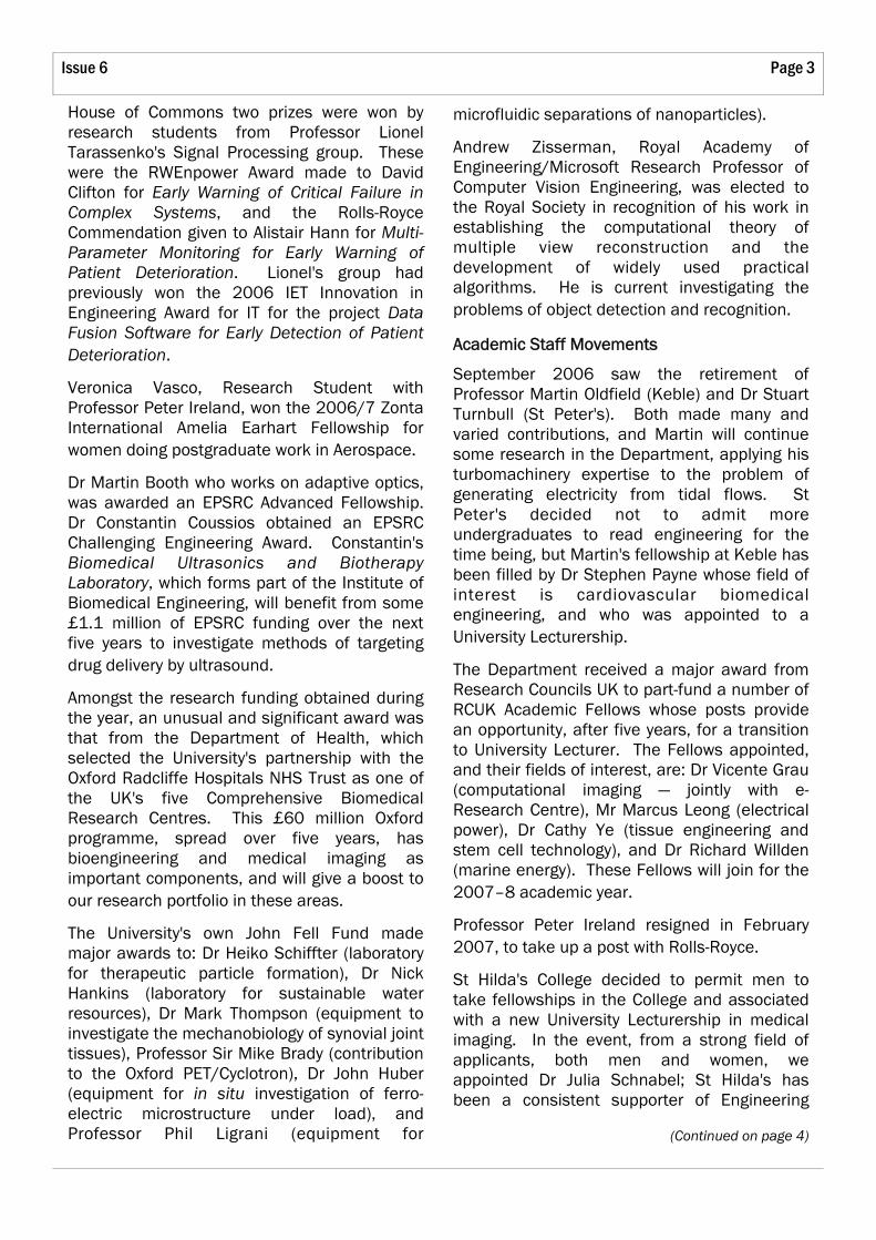
In This Issue
Head of Department's Report 2006 – 2007
Head of Department's Report 2006–2007 ..... 2
Corrosion — The Civil Engineer’s Enemy ........... 5
A Nuclear Renaissance? .................................. 10
PG Lund MBE.................................................... 18
Cryogenic Compressors for Ever! The Development of the "Oxford" Cryocooler ........ 19
The Centenary of the Department .................................... Centre Pages
Obituaries ......................................................... 23
The 19th Jenkin Lecture, 23 September 2006: Railways: The Technical Challenges of their Renaissance ........................................ 27
Jet Engines, and Plastics ................................. 32
The 33rd Maurice Lubbock Memorial Lecture, 10 May 2007: The Entrepreneurial Bug ......................................... 33
Project Exhibition 2007 ................................... 36
Finals and Prelims Prizes Awarded 2007 ...... 38
Page 3 Issue 6
microfluidic separations of nanoparticles).
Andrew Zisserman, Royal Academy of Engineering/Microsoft Research Professor of Computer Vision Engineering, was elected to the Royal Society in recognition of his work in establishing the computational theory of multiple view reconstruction and the development of widely used practical algorithms. He is current investigating the problems of object detection and recognition.
Academic Staff Movements
September 2006 saw the retirement of Professor Martin Oldfield (Keble) and Dr Stuart Turnbull (St Peter's). Both made many and varied contributions, and Martin will continue some research in the Department, applying his turbomachinery expertise to the problem of generating electricity from tidal flows. St Peter's decided not to admit more undergraduates to read engineering for the time being, but Martin's fellowship at Keble has been filled by Dr Stephen Payne whose field of interest is cardiovascular biomedical engineering, and who was appointed to a University Lecturership.
The Department received a major award from Research Councils UK to part-fund a number of RCUK Academic Fellows whose posts provide an opportunity, after five years, for a transition to University Lecturer. The Fellows appointed, and their fields of interest, are: Dr Vicente Grau (computational imaging — jointly with e-Research Centre), Mr Marcus Leong (electrical power), Dr Cathy Ye (tissue engineering and stem cell technology), and Dr Richard Willden (marine energy). These Fellows will join for the 2007–8 academic year.
Professor Peter Ireland resigned in February 2007, to take up a post with Rolls-Royce.
St Hilda's College decided to permit men to take fellowships in the College and associated with a new University Lecturership in medical imaging. In the event, from a strong field of applicants, both men and women, we appointed Dr Julia Schnabel; St Hilda's has been a consistent supporter of Engineering
(Continued on page 4)
House of Commons two prizes were won by research students from Professor Lionel Tarassenko's Signal Processing group. These were the RWEnpower Award made to David Clifton for Early Warning of Critical Failure in Complex Systems, and the Rolls-Royce Commendation given to Alistair Hann for Multi-Parameter Monitoring for Early Warning of Patient Deterioration. Lionel's group had previously won the 2006 IET Innovation in Engineering Award for IT for the project Data Fusion Software for Early Detection of Patient Deterioration.
Veronica Vasco, Research Student with Professor Peter Ireland, won the 2006/7 Zonta International Amelia Earhart Fellowship for women doing postgraduate work in Aerospace.
Dr Martin Booth who works on adaptive optics, was awarded an EPSRC Advanced Fellowship. Dr Constantin Coussios obtained an EPSRC Challenging Engineering Award. Constantin's Biomedical Ultrasonics and Biotherapy Laboratory, which forms part of the Institute of Biomedical Engineering, will benefit from some £1.1 million of EPSRC funding over the next five years to investigate methods of targeting drug delivery by ultrasound.
Amongst the research funding obtained during the year, an unusual and significant award was that from the Department of Health, which selected the University's partnership with the Oxford Radcliffe Hospitals NHS Trust as one of the UK's five Comprehensive Biomedical Research Centres. This £60 million Oxford programme, spread over five years, has bioengineering and medical imaging as important components, and will give a boost to our research portfolio in these areas.
The University's own John Fell Fund made major awards to: Dr Heiko Schiffter (laboratory for therapeutic particle formation), Dr Nick Hankins (laboratory for sustainable water resources), Dr Mark Thompson (equipment to investigate the mechanobiology of synovial joint tissues), Professor Sir Mike Brady (contribution to the Oxford PET/Cyclotron), Dr John Huber (equipment for in situ investigation of ferro-electric microstructure under load), and Professor Phil Ligrani (equipment for

SOUE News Page 4
Science for many years, and it is wonderful that they will now have an official Tutorial Fellow in our subject.
Two Senior Research Fellows joined us during the year: Professor John Fox who joined from Cancer Research UK, works on artificial intelligence and cognitive systems particularly in healthcare; Professor Ashok Bhattacharya, whose interest is in energy systems and nanotechnology, joined from the University of Warwick.
Several Departmental Lecturers left during the year to take up established posts at other universities: Dr Diganta Das, Dr Peter Martin, Dr Menxing Tang and Dr Jun Zang. We wish them all well. A Career Development Fellowship in offshore and coastal engineering was created jointly with St Hugh's College, and has been filled by Dr Jinming Huang.
An election was made to the new Chair in orthopaedic engineering, a 50/50 joint venture with the Nuffield Department of Orthopaedic Surgery. At the time of writing, the election had not yet been accepted.
Buildings
Construction of the Institute of Biomedical Engineering, part of the Old Road Medical Campus development at Headington, started in March 2006 and is progressing on-time and on-budget. Completion is expected in October 2007, and staff will start to move into the building as soon as it is ready. This continues to be a major project, with monthly departmental expenditure earlier this year running at around £1 million. Ken Shuttleworth, who led the design team, is one of the country's leading architects, and we are proud and pleased to be acquiring such a fine new building.
The University has now confirmed its approval for us to establish a new engineering research laboratory in the Axis Point building on the Osney Mead industrial estate. So in 2008 we will start transferring our wind-tunnel and other
(Continued from page 3) facilities from the Southwell building. The £4.3 million project will require careful planning so as to disrupt as little as possible the aerodynamics and heat transfer research that we do for Rolls-Royce and other sponsors.
Elsewhere we continue our rolling programme of refurbishing space to keep it fresh and modern. In the summer of 2007 the Holder common room — scene of much coffee drinking — had a makeover, and the computer suite on Thom floor 6 will be reordered. The ETB drawing office has been modernised, and CAD equipment has replaced the old drawing boards. With a rapid-prototyping machine in one corner, this modern design centre has met with universal approval.
Development and Fund-raising
As part of our centenary celebrations, we are launching an appeal for contributions to the Centenary fund, whose primary objective will be the support of graduate students reading for higher degrees. We hope to raise enough money to support six graduate students on a continuing basis. This University is woefully short of such funds, which seem to be liberally available at competing universities. In this regard we are very grateful to the Medtronic Foundation for their gift of $150,000 for graduate studentships in biomedical engineering. We are also grateful to John Griffiths for his continuing support of the Fozmula undergraduate bursaries.
Last year I drew attention to the significant budget deficit confronting the department. The deficit situation continues, but similar deficits are incurred throughout the non-clinical experimental sciences, and we have been able to pursue our strategy of growth and innovation. The Department advances to start its second century in good heart!
Oxford, June 2007
Head of Department's Report 2006 – 2007 cont.
Page 5 Issue 6
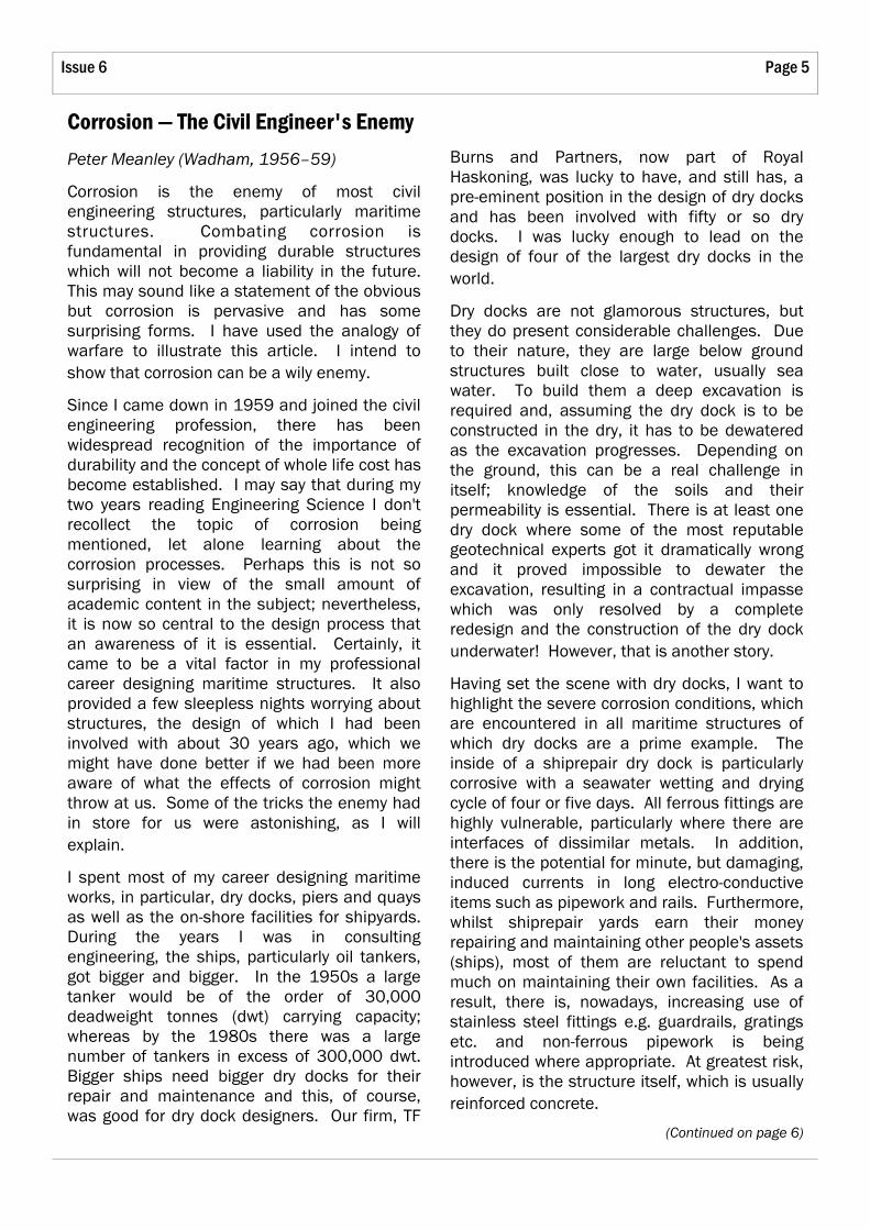
Corrosion — The Civil Engineer's Enemy
Peter Meanley (Wadham, 1956–59)
Corrosion is the enemy of most civil engineering structures, particularly maritime structures. Combating corrosion is fundamental in providing durable structures which will not become a liability in the future. This may sound like a statement of the obvious but corrosion is pervasive and has some surprising forms. I have used the analogy of warfare to illustrate this article. I intend to show that corrosion can be a wily enemy.
Since I came down in 1959 and joined the civil engineering profession, there has been widespread recognition of the importance of durability and the concept of whole life cost has become established. I may say that during my two years reading Engineering Science I don't recollect the topic of corrosion being mentioned, let alone learning about the corrosion processes. Perhaps this is not so surprising in view of the small amount of academic content in the subject; nevertheless, it is now so central to the design process that an awareness of it is essential. Certainly, it came to be a vital factor in my professional career designing maritime structures. It also provided a few sleepless nights worrying about structures, the design of which I had been involved with about 30 years ago, which we might have done better if we had been more aware of what the effects of corrosion might throw at us. Some of the tricks the enemy had in store for us were astonishing, as I will explain.
I spent most of my career designing maritime works, in particular, dry docks, piers and quays as well as the on-shore facilities for shipyards. During the years I was in consulting engineering, the ships, particularly oil tankers, got bigger and bigger. In the 1950s a large tanker would be of the order of 30,000 deadweight tonnes (dwt) carrying capacity; whereas by the 1980s there was a large number of tankers in excess of 300,000 dwt. Bigger ships need bigger dry docks for their repair and maintenance and this, of course, was good for dry dock designers. Our firm, TF
Burns and Partners, now part of Royal Haskoning, was lucky to have, and still has, a pre-eminent position in the design of dry docks and has been involved with fifty or so dry docks. I was lucky enough to lead on the design of four of the largest dry docks in the world.
Dry docks are not glamorous structures, but they do present considerable challenges. Due to their nature, they are large below ground structures built close to water, usually sea water. To build them a deep excavation is required and, assuming the dry dock is to be constructed in the dry, it has to be dewatered as the excavation progresses. Depending on the ground, this can be a real challenge in itself; knowledge of the soils and their permeability is essential. There is at least one dry dock where some of the most reputable geotechnical experts got it dramatically wrong and it proved impossible to dewater the excavation, resulting in a contractual impasse which was only resolved by a complete redesign and the construction of the dry dock underwater! However, that is another story.
Having set the scene with dry docks, I want to highlight the severe corrosion conditions, which are encountered in all maritime structures of which dry docks are a prime example. The inside of a shiprepair dry dock is particularly corrosive with a seawater wetting and drying cycle of four or five days. All ferrous fittings are highly vulnerable, particularly where there are interfaces of dissimilar metals. In addition, there is the potential for minute, but damaging, induced currents in long electro-conductive items such as pipework and rails. Furthermore, whilst shiprepair yards earn their money repairing and maintaining other people's assets (ships), most of them are reluctant to spend much on maintaining their own facilities. As a result, there is, nowadays, increasing use of stainless steel fittings e.g. guardrails, gratings etc. and non-ferrous pipework is being introduced where appropriate. At greatest risk, however, is the structure itself, which is usually reinforced concrete.
(Continued on page 6)
SOUE News Page 6
Corrosion — The Civil Engineer's Enemy cont.
Reinforced concrete has the seeds of its own destruction built into it, which is the steel reinforcement. The steel reinforcement is protected from corrosion by the concrete cover, which provides a passivating alkaline environment. This doesn't last for ever due to the gradual carbonation of the surface of the concrete. Carbon dioxide from the air reacts with the alkali in the cement reducing its pH value. Eventually the carbonation of the cement will reach the level of the steel reinforcement allowing its corrosion to begin. The products of corrosion are extremely expansive and the concrete cover will be "blown" off and spall leaving the reinforcement exposed to further rapid corrosion, loss of area and strength. The greater the thickness of the cover, the greater protection is provided due to the carbonation taking longer to reach the steel reinforcement.
When significant cracking of the concrete has occurred, the effectiveness of the cover to the reinforcement is lost. Cracking of the concrete is usually due to shrinkage of the concrete as it sets. Unfortunately, the problem of drying shrinkage of the concrete was exacerbated in the construction boom of the 1960s and the 1970s when the cement manufacturers changed the formulation of Ordinary Portland cement to produce higher strengths and faster setting times. This suited the contractors who sought faster formwork stripping times and, it must be remembered, it is the contractors who buy the cement. The profession was slow to realise what was happening and in fairness, in many instances it didn't matter. For instance, most reinforced concrete in buildings is clad in other materials and is not exposed to damp and corrosive conditions.
Great efforts have been made to reduce cracking. The concept of purely anti-crack reinforcement, as opposed to reinforcement required for strength, was introduced. The extra reinforcement reduces the amount of strain and thus controls crack width. To maximise its effectiveness the anti-crack reinforcement needs to be close to the surface
(Continued from page 5) of the concrete, but that reduces the depth, and consequently the effectiveness, of the cover. If the reinforcement is the potential seeds of destruction, it can't be sensible to put in more seeds.
A better way forward for maritime structures has been to change the cement or, to be more exact, replace some of the cement with other materials. Widespread use is now made, particularly in the Middle East, of cement replacement using either Ground Granulated Blast Furnace Slag (GGBFS), a by-product of the steel industry, or Pulverised Fuel Ash (PFA), a by-product of coal-fired power stations. Cement replacement reduces the heat of hydration of the chemical reaction of the cement as it sets and, correspondingly, reduces the early shrinkage which is responsible for much of the cracking before the concrete has gained strength. Nevertheless, some cracking is inevitable. Construction joints and crack-inducing joints can be provided to make most of them occur in predetermined positions where suitable seals can be provided. Even so, unplanned cracking will almost certainly occur.
So what else can be done to keep our enemy at bay? Non-ferrous fibre reinforcement can certainly help in dissipating cracks into a large number of microscopic cracks which still maintains the effectiveness of the cover. (It is interesting to note that polypropylene fibre reinforcement was used for the tunnel lining of the Channel Tunnel Rail Link.) The problem is that it is expensive to incorporate in all the concrete in a massive structure, as most maritime structures are, when it is only really needed in the surface. The ultimate solution, in many ways, is stainless steel reinforcement which despite its cost is now being used on some prestigious projects which would not be viable to repair.
All this has led to a reversion, particularly in the Middle East where problems with reinforced concrete have been acute, to mass concrete wherever it can be used. The favoured design for quay walls is now, generally, blockwork

Page 7 Issue 6
incidentally, completed ahead of programme and within budget which was quite refreshing.) It was suggested at the time that, at some time in the future, another dry dock might be built alongside so that the dockside cranes could serve both docks. So, with what we thought was commendable foresight, we provided groups of reinforcing bars protruding from the rear of the concrete dry dock walls so as to be able to tie the two walls together. The bars were below ground water level, so denied oxygen for normal corrosion, coated in bitumen and wrapped in hessian for protection. Sure enough in the early 1990s, we were commissioned to design this further dry dock.
Fortunately, and I count my lucky stars, I insisted early in the design that we inspect the bars which we had left some 15 years before. Although it was considered rather a waste of time, a hole was dug and a pump installed so that we could see them. The water and soil below the bars was black and one of the bars was lying loose. On enquiry, I was told that it had snapped off when hit by the bucket of the excavator. Hang on a minute, snapped off? Since when does a 38 mm diameter high tensile steel bar snap off? Closer inspection revealed that the whole bar was in pristine condition except for the end adjacent to the concrete where there was an indentation as if the bar was made of soft butter and someone had pressed their finger into it. The remaining area was brittle and looked as if the goodness had been sucked out of it. Several of the other bars, although still attached, were similarly reduced in area and could be bent easily. I had seen this phenomenon on steel sheet piling in the UK and it was clearly identifiable, subsequently confirmed by laboratory testing, as anaerobic microbe attack. The fact that the bars were submerged would not have worried the microbes at all and the bitumen and hessian were probably like having butter and jam on their bread as far as they were concerned! Before I left the site that night I had decided, and convinced the client — always essential to carry the client with you in these matters — that the new dry dock wall would not rely on the tie bars which we had so thoughtfully installed only 15 years before.
(Continued on page 8)
made of mass concrete, a technique our engineering grandfathers would have been familiar with.
That is enough about reinforced concrete although there is quite sufficient there to worry about for a material which promised to be the wonder material of the 20th century. Now how about steel sheet piling which is widely used in maritime works? The first, and most obvious, protection is a coating of some sort, such as paint or varnish, applied prior to driving the piles. Unfortunately, the piling process can easily damage the coating and there is no viable way of completely making it good underwater. The next approach is to allow, usually in addition to the coating, an extra thickness of steel as a corrosion allowance. The rate of steel loss due to corrosion varies for the splash, tidal and submerged areas of the piling. Usually, the level of maximum stress occurs in the submerged zone where the required corrosion allowance is less, so, in effect, the larger corrosion allowance required in the splash and tidal zones can be provided at no extra cost.
It would be reasonable to assume that this would be the end of the matter, but the enemy has a nasty surprise waiting which can occur, seemingly randomly, in the form of low-level microbic attack. Yes, there are microbes that secrete chemicals which attack steel. (To those of you who are not familiar with this branch of civil engineering — I promise that I am not making this up!) These micro-organisms can be anaerobic and exist in colonies just below low water level. They are frequently orange in colour and covered in a black slime. The level at which they occur can easily be at or near the level of maximum stress and such an attack can quickly weaken a steel sheet pile wall. As far as I am aware, no-one has come up with a viable form of prevention but at least one firm of contractors is making a steady living repairing steel sheet pile walls using a limpet dam which they have devised for the purpose.
The enemy set an ambush for me with this form of corrosion in Singapore. Our firm had designed a large dry dock in a new shipyard which was built in the 1970s. (It was,
SOUE News Page 8
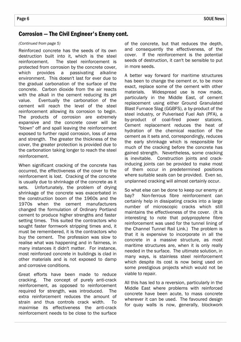
Now we come to the most devastating and unexpected form of corrosion in my experience. To continue the analogy of warfare, this is not so much an ambush as a full-scale surprise attack by the enemy on an undefended flank. To describe it adequately I have to set the scene for you. I mentioned earlier a dry dock that proved very difficult to construct due to the permeability of the soils. This was in Greece in the 1960s and in the 1970s the same client decided to build a further large dry dock (420 m long by 75 m wide by 12 m deep below ground level) in the same shipyard. Perhaps fortunately, he wished to have a design and construct form of contract. The client appointed our firm to draw up the contract documents, check the design and supervise the construction. The contract was won by an Italian consortium who devised a method of dewatering the excavation using bentonite diaphragm walls. Their design exhibited Italian flair and the construction was carried out to a very high standard.
A dry dock, together with its gate, resembles a very large boat which has a tendency to float or be lifted disastrously by the surrounding and
(Continued from page 7) underlying ground water. There are three ways of overcoming this: make the dry dock very heavy — typically for such a gravity dry dock the concrete floor would be about 9 metres thick; anchor the floor down to the underlying rock or soil; or drain under the dock floor such that very little hydrostatic pressure can build up. This last solution ceases to be viable in very permeable soils when the amount of pumping, which must be continuous when the dry dock is dry, becomes too great and the cost of the pumping outweighs the saving in capital cost.
The Italians elected to anchor the dock floor using concrete piles constructed from above ground water level, to avoid any differential head and water flow, with tendons cast into them which were prestressed after the excavation had been carried out and the floor had been cast. The cross section is shown below (Figure 1).
All was well until eight years later when, without warning, a large area of the dock floor (approximately 40 m x 30 m) adjacent the side wall lifted and burst releasing a huge quantity of water which quickly flooded the dock. Fortunately, there was no ship in the dock at
Figure 1: Typical cross-section of new No. 5 dry dock as built in 1977
Corrosion — The Civil Engineer's Enemy cont.
Page 9 Issue 6
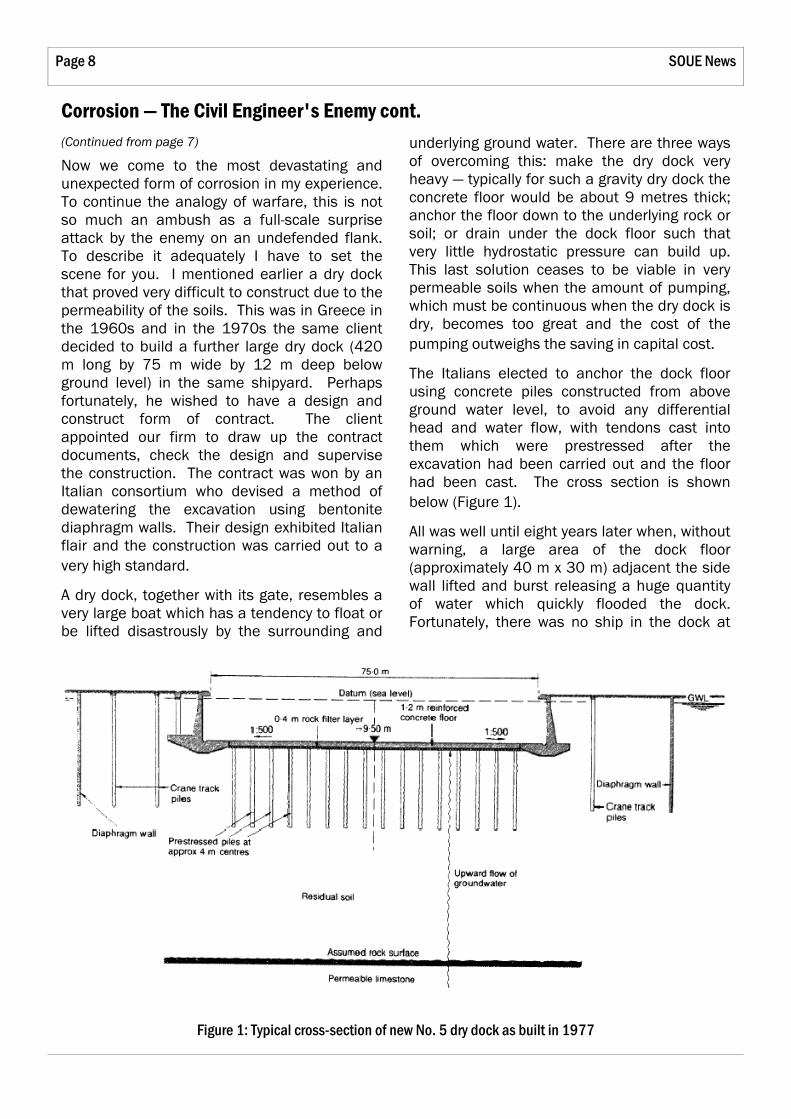
Figure 2: Typical anchor cone with wires attached showing stress corrosion fracture
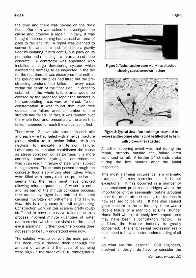
Figure 3: Typical view of an anchorage excavated to expose anchor cones which could be lifted out by hand
with broken wires attached
the time and there was no-one on the dock floor. Our firm was asked to investigate the cause and propose a repair. Initially, it was thought that something had caused an area of piles to fail and lift. A repair was planned to convert the area that had failed into a gravity floor by isolating it with contiguous piles on its perimeter and replacing it with an area of deep concrete. A contractor was appointed who installed a large dewatering system which allowed the damage to be inspected in the dry for the first time. It was discovered that neither the ground nor the piles had lifted but the pre-stressing tendons had failed, in every case, within the depth of the floor slab. In order to establish if the whole failure area would be covered by the proposed repair the anchors in the surrounding areas were examined. To our consternation it was found that even well outside the failure area a number of the strands had failed. In fact, it was random over the whole floor and, presumably, the area that failed happened to reach the critical point first.
There were 12 seven-wire strands in each pile and each wire had failed with a helical fracture plane, similar to a torsion failure, with no necking to indicate a tension failure. Laboratory examination established the cause as stress corrosion or, as perhaps it is more correctly known, hydrogen embrittlement, which can result in failure of steel when subject to high stress. The strands passed through the concrete floor slab within steel tubes which were filled with epoxy resin as protection. It seems that the resin must have cracked allowing minute quantities of water to enter and, as part of the minute corrosion process, free atomic hydrogen had entered the steel causing hydrogen embrittlement and failure. Now this is really scary in civil engineering. Construction work on this scale is pretty rough stuff and to have a massive failure due to a process involving minute quantities of water and corrosion which is not visible to the naked eye is alarming! Furthermore, the process does not seem to be fully understood even now.
The solution was to convert the main part of the dock into a drained dock although the amount of water and the costs of pumping were high (in the order of 3000 tonnes/hour).
A further sobering event was that during the repair, strands outside the failure area continued to fail. A further 14 strands broke during the five months after the initial inspection.
This most alarming occurrence is a dramatic example of stress corrosion but it is not exceptional. It has occurred in a number of post-tensioned prestressed bridges where the importance of the seemingly routine grouting up of the ducts after stressing the tendons is now realised to be vital. It has also caused great concern in the oil industry; there was a recent failure of a manifold at BP's Thunder Horse field where extremely low temperatures may have been a contributory factor. In addition, the Nuclear Industry is greatly concerned. The engineering profession really does need to have a better understanding of all this.
So what are the lessons? Civil engineers, involved in design, do have to consider the
(Continued on page 10)

SOUE News Page 10
durability of the structures they are designing at every stage. They do need to understand the corrosion processes and to have an awareness of the more unusual forms.
As a footnote, I would like to add that I consider myself extremely fortunate to have read Engineering Science at the University. It gave me a very broad academic base which enabled me to learn and practise the art of civil
(Continued from page 9) engineering, as well as its science, throughout my working life. It has been fascinating and varied, taking me from Argentina to Singapore, often exciting, sometimes exhausting and, at times, demanding to the limits of my capability. I wouldn't have missed it for anything!
Reference: GP Martin and AC Arnold. Failure of dry dock floor in Scaramanga, Greece, resulting from stress corrosion damage to anchor pile tendons. Proceedings of the Institution of Civil Engineers, Dec. 1992
Corrosion — The Civil Engineer's Enemy cont.
to pursue development of a plutonium device based on economics and safety. Thus the UK required a fission reactor to generate plutonium. To build a nuclear fission reactor requires a moderator to slow down the fast-moving neutrons released in the fission process, to increase the probability of these neutrons creating further fissions and sustaining the chain reaction. In the late 1940s there were only three credible moderators available — light water, heavy water (i.e. water molecules with a deuterium atom in place of hydrogen) and graphite. Light water reactors require enriched uranium which was not available in the UK at the time, heavy water reactors require a source of heavy water (again not easily available), thus a graphite moderated design was selected for the UK. The US had been working on a graphite moderated, light water cooled reactor but because of interaction between the water and graphite, the moderation was unpredictable with consequent safety concerns. For this reason the UK decided to build a graphite moderated, air cooled reactor (non power generating) to produce plutonium and these were constructed at Windscale in Cumbria and became known as 'the Windscale Piles'.
As the 'Cold War' began the government took the decision to ramp up plutonium production. Further plutonium producing reactors were required, but it was recognised that the 'waste'
Andy Pyle
In recent months there has been significant discussion about the possibility of constructing new Nuclear Power plants in the UK. This article discusses some of the issues which are likely to influence the debate, and reviews some of the available technologies.
History
There are currently ten operational Nuclear Power Stations in the UK, two "Magnox" stations, seven "AGR" stations and one "PWR" station which equates to 19 power reactors in total. There are also 24 power reactors in various stages of decommissioning.
The nuclear power programme grew out of the nuclear weapons programme post World War II. At the end of the war the Government made the decision that, like the USA, Britain was to develop nuclear weapons. In 1946 the US government decided it would not share weapons technology with its WW2 allies and so Britain was forced to develop its weapons in isolation. At the time nuclear explosive devices could be "fuelled" by highly enriched uranium (the Hiroshima bomb) or by plutonium (the Nagasaki bomb). A plutonium bomb is safer to construct and handle, and does not require any enrichment facilities, although a nuclear fission reactor is required to generate plutonium from natural uranium. The UK government decided
A Nuclear Renaissance?
Page 11 Issue 6
technology of choice around the world; the PWR was judged to be cheaper to construct, to be more reliable than gas cooled equivalents, to be constructed of more factory built components (for example there was no need for a complex concrete pressure vessel); and successful construction of a PWR from components manufactured in the UK was predicted to provide UK manufacturing industry with export opportunities. The South of Scotland Electricity Board (SSEB) advocated further AGR construction based on the success of Heysham 2 and Torness, but the CEGB settled on construction of a fleet of PWRs, the first of which, Sizewell B began construction in 1986 and was commissioned in 1995. In 1989, with electricity privatisation looming the plans for the second PWR, Hinkley Point C were put on the back burner, and eventually abandoned.
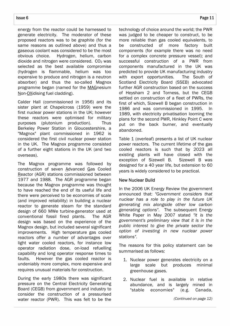
Table 1 (overleaf) presents a list of UK nuclear power reactors. The current lifetime of the gas cooled reactors is such that by 2023 all existing plants will have closed with the exception of Sizewell B. Sizewell B was designed for a 40 year life, but extension to 60 years is widely considered to be practical.
New Nuclear Build
In the 2006 UK Energy Review the government announced that: "Government considers that nuclear has a role to play in the future UK generating mix alongside other low carbon generating options". The subsequent Energy White Paper in May 2007 stated "it is the government's preliminary view that it is in the public interest to give the private sector the option of investing in new nuclear power stations".
The reasons for this policy statement can be summarised as follows:
1. Nuclear power generates electricity on a large scale but produces minimal greenhouse gases.
2. Nuclear fuel is available in relative abundance, and is largely mined in "stable economies" (e.g. Canada,
(Continued on page 12)
energy from the reactor could be harnessed to generate electricity. The moderator of these proposed reactors was to be graphite (for the same reasons as outlined above) and thus a gaseous coolant was considered to be the most obvious choice. Hydrogen, helium, carbon dioxide and nitrogen were considered. CO2 was selected as the best available compromise (hydrogen is flammable, helium was too expensive to produce and nitrogen is a neutron absorber) and thus the so-called Magnox programme began (named for the MAGnesium Non-OXidising fuel cladding).
Calder Hall (commissioned in 1956) and its sister plant at Chapelcross (1959) were the first nuclear power stations in the UK; however these reactors were optimised for military purposes (plutonium production). Thus Berkeley Power Station in Gloucestershire, a "Magnox" plant commissioned in 1962 is considered the first civil nuclear power station in the UK. The Magnox programme consisted of a further eight stations in the UK (and two overseas).
The Magnox programme was followed by construction of seven Advanced Gas Cooled Reactor (AGR) stations commissioned between 1977 and 1988. The AGR programme began because the Magnox programme was thought to have reached the end of its useful life and there were perceived to be economies of scale (and improved reliability) in building a nuclear reactor to generate steam for the standard design of 660 MWe turbine-generator used at conventional fossil fired plants. The AGR design was based on the experience of the Magnox design, but included several significant improvements. High temperature gas cooled reactors offer a number of advantages over light water cooled reactors, for instance low operator radiation dose, on-load refuelling capability and long operator response times to faults. However the gas cooled reactor is undeniably more complex, more expensive and requires unusual materials for construction.
During the early 1980s there was significant pressure on the Central Electricity Generating Board (CEGB) from government and industry to consider the construction of a pressurised water reactor (PWR). This was felt to be the

SOUE News Page 12
A Nuclear Renaissance? cont.
Australia) therefore it is considered a more secure energy source than other fossil fuels.
3. Modern nuclear power stations are considered to be economically viable.
Note that the energy review and subsequent white paper have not recommended construction of new nuclear stations, and indeed, any new nuclear build would have to be entirely financed from the private sector. The white paper describes the government's views on nuclear as 'preliminary' and a consultation document accompanied the white paper. The
(Continued from page 11) public consultation process is due to be completed in October 2007.
Obviously there are significant issues surrounding siting, financing, regulating and planning approval that need to be overcome before any new project will begin. To secure financing of such a large-scale project it is likely that the operator will attempt to secure fixed price sales contracts for a significant proportion of the station lifetime.
International Context
Within the EU there are currently two nuclear power stations under construction — Olkiluoto 3, Finland, where construction began in 2005 and Flamanville, France, where
Location Reactor Type Power Output (MWe) Commissioned Decommissioned Calder Hall 4 Magnox 4 x 50 1956 2003 Chapelcross 4 Magnox 4 x 50 1959 2003 Berkeley 2 Magnox 2 x 138 1962 1989 Bradwell 2 Magnox 2 x 121 1962 2002 Hunterston A 2 Magnox 2 x 180 1964 1990 Hinkley Point A 2 Magnox 2 x 235 1965 1999 Trawsfynydd 2 Magnox 2 x 195 1965 1991 Sizewell A 2 Magnox 2 x 210 1966 2006 Dungeness A 2 Magnox 2 x 219 1966 2006 Winfrith SGHWR 1 x 100 1967 1990 Oldbury 2 Magnox 2 x 217 1968 Planned 2008 Wylfa 2 Magnox 2 x 490 1971 Planned 2010 Dounreay PFR 1 x 250 1975 1994 Dungeness B 2 AGR 2 x 550 1983 Planned 2013 Hinkley Point B 2 AGR 2 x 660 1977 Planned 2011 Hunterston B 2 AGR 2 x 660 1977 Planned 2011 Hartlepool 2 AGR 2 x 605 1983 Planned 2014 Heysham 1 2 AGR 2 x 595 1983 Planned 2014 Heysham 2 2 AGR 2 x 660 1988 Planned 2023 Torness 2 AGR 2 x 660 1988 Planned 2023 Sizewell B 1 PWR 1 x 1188 1995 Planned 2035
Notes:
● There were other experimental reactors which generated electricity on a small scale for the national grid but I have chosen to confine this table to industrial scale generation.
● SGHWR — Steam Generating Heavy Water Reactor — an experimental boiling water reactor. ● PFR — Prototype Fast Reactor, an experimental liquid sodium cooled fast breeder type reactor. ● The remaining operational Magnox plants at Oldbury and Wylfa are unlikely to pursue life
extension. ● It is widely thought that all AGR plants will achieve at least five year life extensions, although there
are some significant technical issues still to be overcome.
Table 1: List of UK nuclear power reactors in order of construction
Page 13 Issue 6
construction is due to start in late 2007. Both of these projects involve construction of the AREVA designed European Pressurised Water Reactor (EPR). The French remain committed to a nuclear power programme, as are Japan, South Korea, China and India. On the other hand, Germany and Sweden have existing nuclear power stations which their national governments have committed to phasing out. In the USA three consortia are pursuing an "early site permit" to evaluate specific sites for construction of new nuclear units.
Across the globe there is a trend to pursue life extension of existing nuclear facilities. The large initial cost of a nuclear plant means that if replacement of the components is technically feasible, it is probably cost-effective to extend the life of the plant, even if a long shutdown is required. Several nuclear plants around the world are pursuing agreement in principle to a 60 year operational lifetime (compared to original design lives of 30–40 years).
It should be noted that whilst life extensions are being investigated, it is unlikely that any operating UK gas reactors will achieve more than a 40 year life.
Siting
The process for determining the site of a new nuclear reactor will be extremely controversial. It is probable that new build in the UK will be on sites adjacent to existing nuclear facilities (operating and decommissioned power stations or experimental facilities). Most of these sites have connections to the supergrid, and all have local skilled labour, for employment on site and in supporting infrastructure. The sites are all suitable from a geological point of view and there are supplies of cooling water available (most sites are coastal). In general the local population is supportive of nuclear stations and the benefits they bring to the economy. In addition, with existing facilities approaching the end of their lifetime, new build could offer the workforce a transition into a new facility.
Other sites have been considered in the past, and sites close to existing conventional power stations have many of the required characteristics, but it is most likely that the first
sites to be considered for a new "fleet" would be where there are existing nuclear facilities.
The process for deciding on a suitable site is most likely to involve consultation at a national level, once candidate sites have been chosen. The ongoing public consultation into whether to construct new nuclear power plants is accompanied by a separate consultation document on 'Strategic Siting Assessment Processes for New Nuclear Power Stations'. The outcome of this consultation is likely to be a new siting assessment process.
It is considered likely that the UK would return to the practice of building twin reactor stations at each site, to provide economies of scale at each location and to minimise the number of nuclear reactor locations.
Regulation
Construction of a new nuclear station in this country will raise some unique issues which have not yet been faced in the UK. In the past the Central Electricity Generating Board was responsible for determining nuclear power strategy. In future there may be competing organisations proposing to build on different sites, using different reactor designs, with different safety and operational philosophies.
The UK regulator, the Nuclear Installations Inspectorate (NII), does not have the resources to assess all technologies and determine which of these is acceptable for the UK. Thus there is a risk that following detailed engineering assessment the NII may require redesign work or insist on the addition of engineered safety features. It is obvious that this will increase the cost, may lead to delays in construction, and may even adversely affect plant reliability. Such design changes could make UK reactors unique in comparison with nominally identical reactor types elsewhere in the world.
As a result the government have announced their intention to utilise a Generic Design Assessment (GDA) process whereby NII will undertake an up-front assessment of designs submitted by vendors. This assessment process is expected to take three to four years.
(Continued on page 14)

SOUE News Page 14
A Nuclear Renaissance? cont.
It is anticipated that after GDA is complete, the design will be frozen and can then be assessed for its suitability at a particular site, which is expected to be relatively straightforward. Planning approval must then be sought for construction.
Planning Approval
It is widely accepted that a repeat of the more than two years of public inquiry into the construction of Sizewell B would prevent private investors from considering nuclear power. In May 2007 a government White Paper on Planning Policy made provision for a National Planning policy and a new central planning body to make decisions regarding major strategic infrastructure developments (particularly power generation) such as nuclear stations. This white paper is in the consultation phase at the time of writing and therefore the final outcome is not yet clear.
Technologies
There is a wide range of Nuclear generation technologies available but I have chosen to discuss four: the AREVA EPR, the Westinghouse AP1000, the AECL CANDU and the GE ESBWR. All four of these designs have been submitted to NII for Generic Design Assessment.
It should be noted that the construction of a new generation of nuclear power plants in the UK offers an opportunity. Because of the existing fleet of gas-cooled reactors, and the "one-off" at Sizewell B, the UK is not "bought in" to any currently available technology. Unlike many other nations, the UK has an opportunity to forge a path in a new direction if we choose to do so. This strategy is not without risks; however the pre-eminence of light water technology reactors in the world does not mean that these are the "best" designs, just that these have been more successfully marketed.
Note that no 'fast' breeder type reactor is available commercially — all of the technologies being considered for power generation at this stage are thermal nuclear fission reactors.
(Continued from page 13) AREVA European Pressurised Water Reactor (EPR)
The EPR is a pressurised light water reactor based on the successful French N4 and German KONVOI PWR designs. AREVA (a consortium of Framatome and Siemens) has orders for two EPRs in Europe (in Finland and in France).
The basic EPR design is a 1600 MWe 4-loop (i.e. four steam generators) PWR, with a thermal efficiency of 36% and a design life of 60 years. By redesign of the fuel cycle and refuelling interval, the EPR is a more efficient unit than previous PWR designs.
The EPR adds additional safety features, including four independent 'trains' of automatic safety systems to improve tolerance to fault situations, a containment structure designed to withstand aircraft impact, and severe accident mitigation against the possibility of core melt.
Because the EPR is a conventional PWR, with engineered safety features, building on existing reactor technology, it is the design most like Sizewell B and as such would probably be the most straightforward to license in the UK. However, some commentators consider that the size of the EPR makes it unwieldy for a relatively small national grid, since in the event of a random reactor shutdown, the loss of 1600 MWe may cause significant grid instability. Like all existing UK nuclear stations the EPR makes use of diverse and redundant automatic protection systems designed to operate to protect the reactor in the event of a fault. However, other reactor designs make use of passive safety features, without the need for systems to operate to maintain safety. There is a clash between these two design philosophies but it may be that the EPR is considered to be the last design of a previous generation.
In 2006 the government announced a strategic nuclear technology alliance with the French. Because of this alliance, and the similarity to Sizewell B many experts consider that the next UK nuclear reactor is most likely to be an EPR.
Page 15 Issue 6
Westinghouse Advanced Passive (AP) 1000
The Westinghouse AP1000 is a ~1150 MWe pressurised light water reactor.
The basic electricity generating unit is very similar to the EPR design, although it is based on only two loops rather than four, and achieves a thermal efficiency closer to 33%. The size of the generating unit is similar to previous generations of PWR (and very similar to Sizewell B), therefore it does not have the same concerns regarding grid stability.
It is in the design of the safety features that the AP1000 differs from existing PWRs. The principle of the AP1000 is to simplify the design of the reactor by providing passive protection from faults and hazards and thus avoid the need for complex control schemes, and reduce the burden on operators during faults. The idea is to achieve safety by design, rather than the established 'defence in depth' (multiple diverse and redundant safety systems) approach. A good example is the provision of reactor cooling in a loss of
(Continued on page 16)
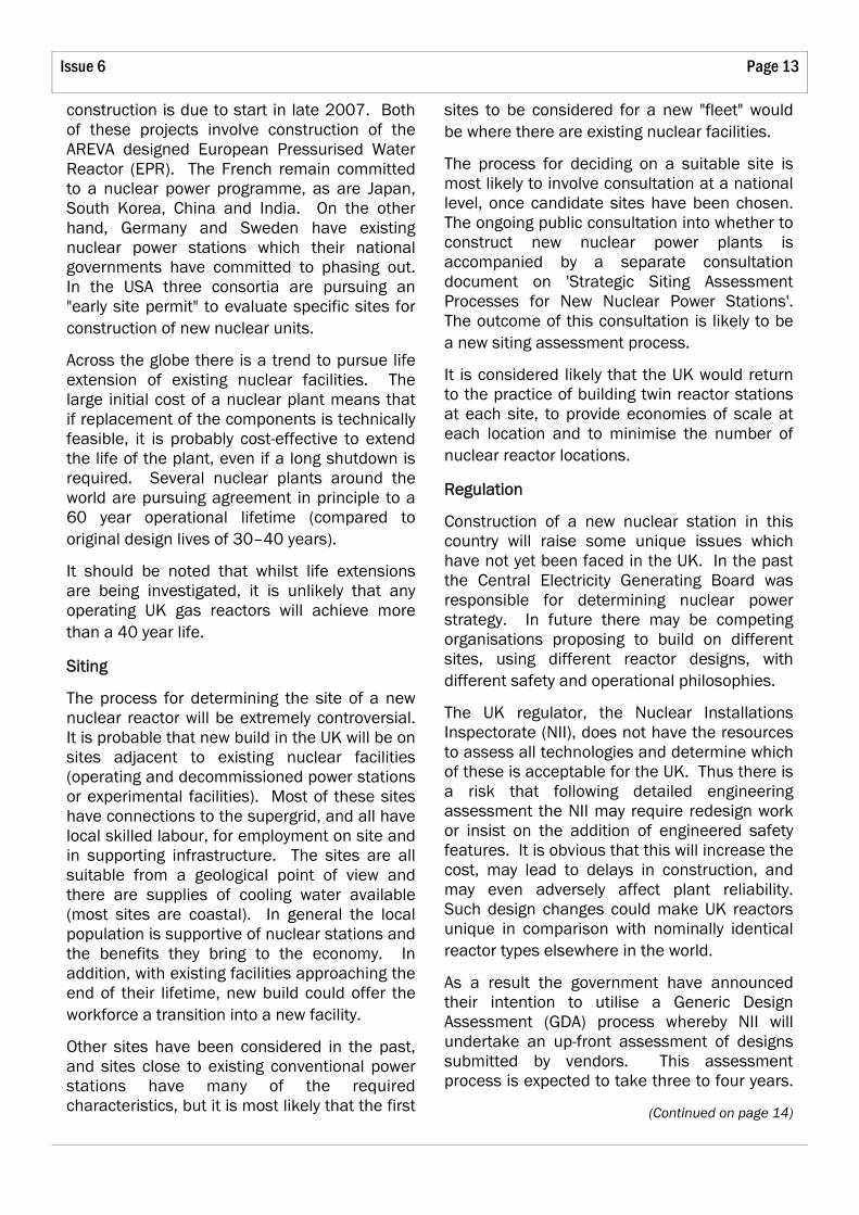
Layout of AREVA EPR reactor
Key:
1. Reactor pressure vessel
2. Steam generators
3. Pressuriser
4. Reactor coolant pumps
5. Inner containment wall
6. Outer containment wall
7. "Core catcher" — area for collection of molten fuel in severe accident
8. Control room
9. Diesel generator buildings
10. Turbo-generator building
SOUE News Page 16
A Nuclear Renaissance? cont.
electrical grid connection fault. The AP1000 is able to maintain core cooling via natural circulation of cooling water, and provision of an induced-draught cooling tower as part of the containment structure, thus avoiding the need for standby emergency generators.
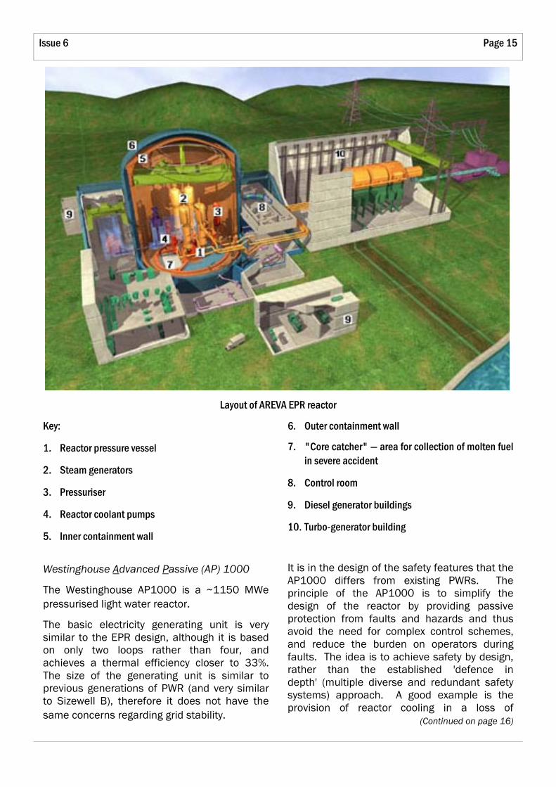
Diagram of AP1000 reactor
The intent is that by simplifying the plant, the initial cost of the reactor is reduced, and the potential for accidents is reduced because there is less plant to maintain, or malfunction. Westinghouse claim that the AP1000 requires 50% fewer valves, 83% less pipework, 87% less control cabling and 35% fewer pumps than existing PWR designs of a similar capacity. In developing the AP1000 Westinghouse have challenged the accepted wisdom that employing diverse and redundant automatic protection systems is the "best way" to safeguard a nuclear reactor. It is not yet clear whether the passive safety systems will prove popular with operators and regulators.
The challenge for Westinghouse is to convince the UK regulators that the passive design features can achieve the required performance — it is a radical departure from any reactor constructed in Britain. In addition, no AP1000 has yet been constructed and there is a
(Continued from page 15) significant risk that the construction costs will rise.
However, the claimed low construction and operating costs, and the passive safety features must make the AP1000 a strong contender.
Atomic Energy of Canada Ltd (AECL), CANDU 6/CANDU ACR
The CANDU 6 (CANadian Deuterium Uranium) reactor design has become a popular alternative to the more common light water reactor technologies. The CANDU reactor is a heavy water moderated, light water cooled reactor. There are 32 CANDU reactors across the world and AECL offer a CANDU 6 design of 750 MWe capacity and are developing the ~1000 MWe ACR (Advanced CANDU Reactor)
The CANDU reactor is extremely flexible in terms of the fuels it can use, for instance it can be fuelled with natural uranium and in this case there would be no need for complex, energy intensive and costly uranium enrichment facilities required for conventional light water technologies which may be an attractive feature. When using natural uranium as a fuel the fuel dwell within the reactor ('burn up') is low in comparison with using enriched fuel (approximately ¼ of the burn up of a light water reactor). Thus the cost avoided in enrichment may be spent on extra fuel or reprocessing. The CANDU reactor can be refuelled on load (a feature it shares with gas cooled reactors), which is attractive from a commercial viewpoint and important given the short fuel dwell if natural uranium fuel is used. The flexibility of fuelling of the CANDU design is one of the key attractions, for example within certain constraints it is possible to remove a 'used' fuel assembly from a PWR and install it into a CANDU reactor and continue to generate power.
The fact that the reactor can be refuelled on load means that the containment building is designed for access at power (not the case for most light water cooled reactors) and therefore there is better access for maintenance and
Page 17 Issue 6
fault diagnosis.
In addition, AECL license the rights to build CANDU reactors, thus it is possible that UK manufacturing industry could benefit from construction of a CANDU reactor.
A heavy water moderated, light water cooled reactor has operated in the UK already (SGHWR at Winfrith) and there is also some experience within the UK of this technology since prior to financial collapse in 2004, British Energy owned and operated the Bruce Nuclear Plant in Ontario (which consists of eight CANDU reactors). As with the AP1000 the smaller size of the CANDU generating units gives little cause for concern with regard to grid stability.
The downside of the CANDU design is that the technology is relatively unusual, it requires a heavy water moderator, and the CANDU 6 units are small in size, but as discussed there are many advantages that make the CANDU a popular alternative choice.
General Electric, Economic Simplified Boiling Water Reactor (ESBWR)
The ESBWR is an evolution of previous General Electric Boiling Water Reactor designs, being a 1560 MWe, light water cooled reactor. In a boiling water reactor there is no secondary heat removal circuit. Light water is passed over the fuel and boils to form steam within the reactor — the steam generated is then passed direct to the turbine set thus increasing the cycle efficiency (the ESBWR cycle efficiency is predicted to be ~35%). Although this delivers improved efficiency it complicates turbine maintenance because of radiological considerations (the turbine is in direct contact with the nuclear fuel coolant), but the SGHWR at Winfrith utilised this type of turbine cycle and thus it is not without precedent in the UK.
Like the EPR the design builds on previous reactor technology using some identical components but like the AP1000 it makes use of passive operating and safety features. Thus the ESBWR may be seen as a compromise between the competing designs.
One key feature is the elimination of circulation
pumps to drive water around the pressure vessel, with the ESBWR relying on natural circulation instead. This concept is extended to the safety systems, which also rely on passive features, for instance avoiding the need for emergency power on site.
Also, like the EPR, the basic generating unit of an ESBWR is very large at ~1600 MWe, and therefore there are the same concerns with regard to electrical grid stability in the event of an unplanned shutdown.
A Boiling Water Reactor has never been built on a commercial scale in the UK, but BWR technology is popular throughout the world (especially in the USA and Japan). The ESBWR offers a compromise between the EPR and AP1000, builds on existing successful designs and BWR technology is in wide use, therefore it is a strong contender.
Nuclear Waste Disposal
Conventional reactor technologies "burn" only approximately 3% of the fissile material in the fuel before it becomes uneconomic. Reprocessing technology is designed to extract the spent fuel to enable the remaining 97% to be re-used. Reprocessing is controversial owing to the generation of concentrated waste, the separation of weapons grade isotopes and the uncertain economics. Currently only four countries in the world undertake reprocessing on a commercial scale (UK, France, Russia and Japan).
Because of reprocessing, spent nuclear fuel may be considered a resource (because new fuel can be made from old) or alternatively it may be considered as waste.
Currently the UK has a "stockpile" of ~1500 m3 of high-level radioactive waste and, in addition, significant volumes of spent fuel considered 'resource' and therefore not classified as waste. The high-level waste consists of a mixture of different radio-isotopes, some of which will take 'only' a few hundred years to become safe, but others will take many hundreds of thousands of years to decay such that they are safe.
(Continued on page 18)

SOUE News Page 18
A Nuclear Renaissance? cont.
In addition to the high-level waste, nuclear power reactors generate significant quantities of intermediate-level waste (mostly components irradiated within the reactor pressure vessel). To date there is no agreed means to dispose of either high-level or intermediate-level wastes in the UK. Other countries are significantly further on in the process of engineering a safe waste disposal route.
In 2006 the Commission for Radioactive Waste Management (CoRWM) concluded that the best option for "final disposal" was to build a sub-surface geological repository. The key advantage offered by geological disposal is that timescales of hundreds of thousands of years are short in geological terms. By choosing a site carefully, geologists can have a high degree of confidence of how the rock formations will behave. The deep geological repository is the technology of choice for many nations, and several have progressed to very advanced feasibility studies and experimental geological facilities (for example the Yucca Mountain facility in the Nevada desert, USA).
The lack of a disposal site and agreed technology creates significant problems for those sites currently being decommissioned since the detail of the packaging for the waste cannot be finalised until the design of the disposal facility is agreed. Therefore interim solutions must be sought for all the decommissioned power plants, and this may
(Continued from page 17) lead to waste being re-packaged in future. Clearly this in uneconomic, but it is also bad radiological practice since operators will have to be exposed to the waste more than once. Thus solving the issue of the waste disposal is considered cr i t ical to progressing decommissioning effectively and therefore completing the final economic assessment of nuclear power.
Progress in the disposal of nuclear waste in the UK requires detailed assessment of suitable geological formations and the commitment to research suitable medium term storage options whilst the final disposal site is determined, designed and constructed.
Andy Pyle read Engineering Science at Balliol, 1995–9, and is now Group Head, Programmes and Design Engineering, at Heysham 2 Nuclear Power Station, an AGR plant in Lancashire, owned by British Energy. He has worked for British Energy for eight years, in a variety of roles within Central Engineering Support, and at Heysham 2. He is a Chartered Mechanical Engineer, sitting on the Nuclear Power Committee of the IMechE, and is also a member of the Institution of Engineering and Technology. In 2005 Andy attended the inaugural World Nuclear University Summer Institute, held at the Idaho National Engineering Laboratory, USA. Before joining British Energy Andy was sponsored through his Oxford degree by Siemens Power Generation Ltd (formerly CA Parsons of Newcastle).
PG Lund MBE
We congratulate Peter Lund on the award of an MBE in the New Year's Honours List, for "Services to the community in Oxfordshire". The local newspaper was a little more explicit, and explained that Peter has been the organiser of the Best Kept Village competition for Oxfordshire Rural Community Council, and it quoted him as saying "Like many of these things, the honour really belongs to other
people and I seem to be the lucky one who had his name put forward".
For the benefit of younger members who may not have known him, Peter was a lecturer in the Department, and engineering tutor at Christ Church, for many decades before his retirement in the early 1990s, and was SOUE Secretary from 1991 to 2004.
Page 19 Issue 6
Cryogenic Compressors for Ever! The Development of the "Oxford" Cryocooler
Paul Bailey
The Need for Cooling
In the late 1970s there was a desire to learn more about the Earth's atmosphere, and a satellite instrument called ISAMS (Improved Stratospheric And Mesospheric Sounder) was designed to measure the vertical profiles of temperature in the atmosphere and also a number of the atmospheric constituents.
The signal-to-noise ratio of this instrument would be enhanced if the sensor was kept at a temperature of about 80 K. On the face of it this seems easy — space is a very cold place — but in fact, satellites are NOT cold. Because of the size and mass of radiators, satellites are typically at about 300 K, so a sensor at 80 K would need to be cooled in some way. The thermodynamic cycle most suitable for this was the Stirling cycle, a gas cycle which, in theory, approaches the ideal 'Carnot' efficiency.
Originally developed for producing power, the Stirling cycle can also be used for refrigeration. The main components are a compressor, which produces pressure pulsations, and a cold head, which contains a 'displacer piston' and heat exchangers. The displacer is synchronised with the compressor piston and is usually operated at a phase angle of about 90° to the compressor piston. Hence when the gas is expanding, much of the gas is at the cold end, and takes in heat from its surroundings, and when it is compressed, the gas has been moved to the warm end, where heat is rejected. By this means heat is pumped from a low temperature to a high temperature.
The specification for this cryocooler was:
● 1 Watt of cooling at 80 K, rejecting heat at 300 K
● 10 year life
● 230 K to 340 K survival temperature
● Survival of launch vibration (non-operating)
● Low exported vibration
● High efficiency
● NO MAINTENANCE POSSIBLE
The last requirement was the problem. A simple single cylinder reciprocating machine has at least five bearings, and all of these need to be lubricated. With the 'cold end' of the cryocooler at 80 K, any oil would solidify and block the heat exchangers. Therefore the unit must be oil free.
There are a variety of oil free compressors — oil separators, ceramic pistons and metal or rubber diaphragms have all been used, but all of them would need periodic maintenance to survive ten years.
Early Development
The solution to this was provided by Dr Gordon Davey, who adapted a 'Pressure Modulator' developed by Oxford's Atmospheric Physics Department. The keys features of the new cryocooler were:
Clearance Seals are not seals — they are leaks! If the radial clearance between piston and cylinder is made small enough, the resulting leakage can be tolerated. The clearance needed is 10–20 µm, and this requires both piston and cylinder to be very cylindrical, with good concentricity maintained between them.
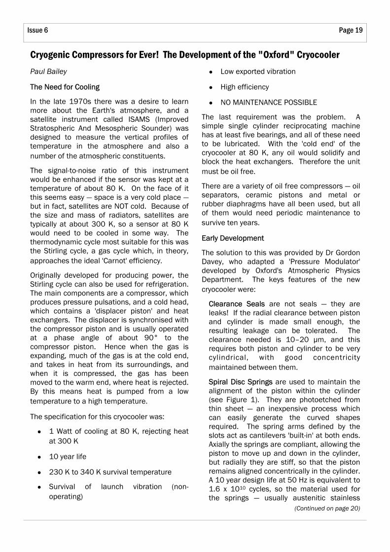
Spiral Disc Springs are used to maintain the alignment of the piston within the cylinder (see Figure 1). They are photoetched from thin sheet — an inexpensive process which can easily generate the curved shapes required. The spring arms defined by the slots act as cantilevers 'built-in' at both ends. Axially the springs are compliant, allowing the piston to move up and down in the cylinder, but radially they are stiff, so that the piston remains aligned concentrically in the cylinder. A 10 year design life at 50 Hz is equivalent to 1.6 x 10¹⁰ cycles, so the material used for the springs — usually austenitic stainless
(Continued on page 20)
SOUE News Page 20
Cryogenic Compressors for Ever! cont.
steel or beryllium copper — must have a "fatigue limit", and the spring is designed so that the peak stress is safely below this limit.
Figure 1: Spiral disc spring
Linear Motion. A 'loudspeaker' type moving coil, permanent magnet motor is used to drive the compressors. With the motor, piston and springs all aligned on a common axis, there are negligible sideways forces during operation. A typical assembly
(Continued from page 19) suspended on spiral springs would have a radial movement of ± 3 µm for a stroke of ± 5 mm.
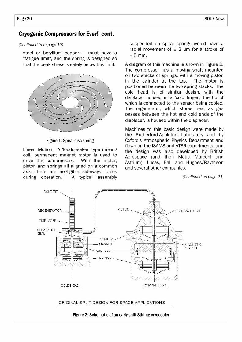
A diagram of this machine is shown in Figure 2. The compressor has a moving shaft mounted on two stacks of springs, with a moving piston in the cylinder at the top. The motor is positioned between the two spring stacks. The cold head is of similar design, with the displacer housed in a 'cold finger', the tip of which is connected to the sensor being cooled. The regenerator, which stores heat as gas passes between the hot and cold ends of the displacer, is housed within the displacer.
Machines to this basic design were made by the Rutherford-Appleton Laboratory and by Oxford's Atmospheric Physics Department and flown on the ISAMS and ATSR experiments, and the design was also developed by British Aerospace (and then Matra Marconi and Astrium), Lucas, Ball and Hughes/Raytheon and several other companies.
(Continued on page 21)
Figure 2: Schematic of an early split Stirling cryocooler
Page 21 Issue 6
Second Generation Cryocoolers
The first generation machines were expensive to make and difficult to assemble, and there was a requirement for smaller, lower cost machines that would be suitable for non-space use. To meet these requirements, an 'Integral' cryocooler was developed, which had the following characteristics:
● A single unit, with the displacer integral with the compressor
● Moving cylinder and fixed piston
● The long thin shaft of the early machines was replaced by a short fat tube acting as the moving cylinder
● Only one motor — the displacer is driven pneumatically by the pressure pulsation
● More robust and easier to assemble
These units were developed in partnership with the Hymatic Engineering Company (now Honeywell Hymatic) for 'tactical' and commercial markets, and there was also a transfer of technology to TRW (now part of Northrop Grumman Space Technology (NGST)). These licensing agreements are made through Isis Innovation, the University of Oxford's technology transfer company.
The Third Generation
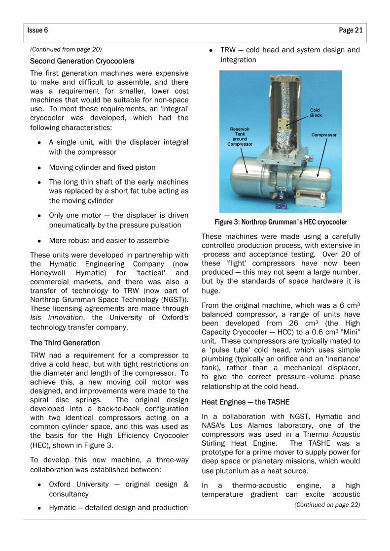
TRW had a requirement for a compressor to drive a cold head, but with tight restrictions on the diameter and length of the compressor. To achieve this, a new moving coil motor was designed, and improvements were made to the spiral disc springs. The original design developed into a back-to-back configuration with two identical compressors acting on a common cylinder space, and this was used as the basis for the High Efficiency Cryocooler (HEC), shown in Figure 3.
To develop this new machine, a three-way collaboration was established between:
● Oxford University — original design & consultancy
● Hymatic — detailed design and production
(Continued from page 20) ● TRW — cold head and system design and integration
Figure 3: Northrop Grumman's HEC cryocooler
These machines were made using a carefully controlled production process, with extensive in-process and acceptance testing. Over 20 of these 'flight' compressors have now been produced — this may not seem a large number, but by the standards of space hardware it is huge.
From the original machine, which was a 6 cm3 balanced compressor, a range of units have been developed from 26 cm3 (the High Capacity Cryocooler — HCC) to a 0.6 cm3 "Mini" unit. These compressors are typically mated to a 'pulse tube' cold head, which uses simple plumbing (typically an orifice and an 'inertance' tank), rather than a mechanical displacer, to give the correct pressure–volume phase relationship at the cold head.
Heat Engines — the TASHE
In a collaboration with NGST, Hymatic and NASA's Los Alamos laboratory, one of the compressors was used in a Thermo Acoustic Stirling Heat Engine. The TASHE was a prototype for a prime mover to supply power for deep space or planetary missions, which would use plutonium as a heat source.
In a thermo-acoustic engine, a high temperature gradient can excite acoustic
(Continued on page 22)
SOUE News Page 22
Cryogenic Compressors for Ever! cont.
oscillations in a gas. If this source of sound is connected to a piston which resonates at the same frequency, it is possible to get power out of the system.
In this prototype TASHE, an HEC compressor was modified by increasing the size of the pistons, and these were mated to a thermo-acoustic engine: instead of converting electricity into pressure pulsations, the compressors acted in reverse — absorbing acoustic power and generating AC electricity. The complete system achieved a thermal efficiency of 18% with an electrical power output of 40 W.
Valved Compressors
All of the machines mentioned so far have an oscillating flow — the compressors are "AC" devices used to produce a pressure oscillation. By adding valves, these compressors can be used to create a "DC" flow through a system. One application for this is in conventional vapour compression refrigeration, or to produce a flow for a Joule-Thomson (J-T) cooler.
An example of the latter is a system being developed by NGST to cool the Mid-Infra-Red Instrument (MIRI) on the James Webb Space Telescope — the successor to the Hubble. The MIRI instrument requires 65 mW of cooling at 6 K, and the system being developed consists of a three stage pulse tube cooler powered by an HCC compressor, which is used to pre-cool the bottom stage, which is a J-T system with a valved HEC compressor.
The prototype valved compressor was built by Oxford and Hymatic, and is being tested on the complete J-T system by NGST.
Computer Cooling
Oxford has just started a new project which will further develop the valved linear compressor. Computers have reached the stage where performance is being limited by the heat generated in CPU chips. Because they are very small, the heat flux required to cool them is
(Continued from page 21) higher than can be obtained with a forced convection heat sink clamped to the top surface.
Suitable heat fluxes can be obtained by evaporative cooling, especially if a very fine extended heat transfer surface can be formed into the surface of the chip, which would become the 'evaporator' of a conventional vapour compression refrigerator. The problem with an 'off-the-shelf' system is the presence of oil, which circulates with the refrigerant, and would quickly find its way to the fine extended surface, which it would block.
The Oxford compressors provide a solution to this problem — the clearance seal/spring system requires no lubrication and produces no debris that would foul the extended surface. Oxford has just started a three-year project, in collaboration with Newcastle University and London South Bank University, to develop this technology.
The moving coil compressors used to date are too expensive to be used in applications such as these, so a new low-cost moving magnet linear motor has been designed. Instead of magnetic yokes machined from pure iron, and delicate moving coils, the new motor uses silicon-iron laminations and conventional windings similar to those in a standard rotary motor.
Oil Free Compressors
There are several other benefits of oil free compressors.
● The absence of oil makes these compressors suitable for use with high purity and medical gases, where oil cannot be tolerated.
● Oil acts as a catalyst for the breakdown of refrigerants at high temperatures in vapour compression systems. Oil free compression could widen the choice of refrigerants and increase the possible temperature range.
● It is inefficient to control conventional

Page 23 Issue 6
refrigerators by on/off cycling. The output of a linear compressor can be easily modulated by reducing the stroke, which can be done by dropping the supply voltage.
Do They Live Forever?
No.
But they should last a long time; there are very few failure mechanisms in these simple machines — the springs are unlikely to fail, there is no wear and no oil or debris to cause blockages.
There is the potential for electrical failure within the machine, particularly soldered joints, but failure of external controls and drive electronics is much more likely.
The one definite failure mode is gas leakage. Space cryocoolers are typically tested to ensure
that the leak rate is less than 5 x 10⁻⁷ mbar l/s, which is equivalent to a pressure drop of about 1% in 25 years; pressure drops of 5% or so would be tolerable before the efficiency would fall significantly.
Life test data compiled for "Oxford" type machines in 1998 showed a total of 49 machine-years with no failures. More recent data from cryocoolers flown on satellites shows one failure in 38 machine-years (this was a displacer failure — the compressor was OK).
The future prospects of the "Oxford" compressor are very promising. The third generation compressors are very compact and robust, and have a high performance. They have been used for valved compressors and as a part of a heat engine. The new moving magnet concept will lead to a lower cost machine, and this will encourage its much wider use.
Obituaries
Herby Sixsmith, 1914–2007
Brian A Hands
Dr Herbert (Herby) Sixsmith, cryogenic engineer and Fellow of Wolfson College, died peacefully on 17 June in Vermont aged 93. He had become increasingly frail physically in recent years, and during his last few months was intermittently in hospital with heart problems.
Herby was educated at Kilkenny College, Kilkenny, Ireland and at Trinity College, Dublin, where he graduated with an honours degree in physics in 1940. Early in 1940 he joined the Admiralty Research Establishment working on the cavity magnetron at the University of Birmingham. This work was later moved to the British Thomson-Houston Company in Rugby.
After the war, Herby moved to the Cavendish Laboratory, Cambridge, where he continued work on the magnetron. In 1948 he was appointed lecturer in physics at Reading University. He commenced work on a vacuum tube scale-of-ten counter. This needed a high
vacuum which at that time could be obtained only using a mercury vapour diffusion pump with a cold trap cooled by liquid air or liquid nitrogen. There was no supply of liquid air at the University. Whenever some was needed, it had to be obtained from Imperial College London. In response to a telephone call, someone would put a two-gallon container of liquid on to a train at Paddington, and someone from the University would meet the train at Reading and collect the container. There was a clear need for a generator of liquid air or nitrogen at the University. Conventional liquefiers at that time needed supply pressures in the range of 100 to 200 bar and an operator to keep them adjusted and running. Herby became fascinated with the possibilities of a reverse Brayton cycle with a turbine expander to provide the refrigeration. The pressure would be much lower (around 5 bar) and the compressor would therefore be simpler. To supply the needs of a small physics laboratory, the turbine would have to be small, with a rotor diameter of about 10 mm and a rotational
(Continued on page 24)

SOUE News Page 24
Obituaries cont.
speed of about 4000 revolutions per second. This was a challenge worth pursuing. Herby invented and developed a gas-lubricated bearing which would work reliably at these high speeds. When running, the relative velocity of the bearing surfaces is about 200 metres per second, the clearance is less than about 2.5 microns and the two surfaces never touch. There is no wear and no risk of contamination with oil. The turbine was incorporated in a small liquid air machine which ran unattended and produced about 5 litres per hour of liquid. Herby wrote his thesis on this machine and was awarded a PhD. The turbine was adopted and further developed by the British Oxygen Company and used in the LINIT liquid nitrogen generator.
In 1959, Herby joined the cryogenics division of the National Bureau of Standards at Boulder, Colorado, where he developed a small helium expansion turbine. One of his colleagues there, Vincent Arp, remembers that he obtained the use of an old lathe which he set up in an out-of-the-way location into which he would disappear and emerge some time later with components for his turbine, machined to a precision which the workshop had said was not possible. He was clearly gifted not only as an inventive designer but also as a skilled machinist.
In 1963, he moved to the Department of Engineering Science in Oxford, where he worked on a gas-bearing compressor for helium. When he retired (at the age of 67) in 1981, he found employment at Creare Inc., a small research and development company in Hanover, New Hampshire, USA, with a particular interest in cryogenics, where he worked on the development of miniature cryogenic machinery, used later for an application on the Hubble Space Telescope. On this, a critical instrument module, the Near Infrared Camera and Multi-Object Spectrometer (NICMOS) uses cryogenically cooled detectors for deep space astronomical observations. The reservoir of solid nitrogen that provided the cooling became exhausted sooner than expected and signals from NICMOS came to an
(Continued from page 23) end.
In 1997 Creare undertook the construction of a reverse-Brayton cryocooler to restore the refrigeration. With miniature rotating machinery, the vibration is negligible. This is a major advantage since cryocooler vibration reduces the pointing accuracy of the telescope. The Creare cryocooler incorporated a miniature centrifugal compressor, a miniature turboexpander and a miniature circulator to transfer heat from the detectors to the cryocooler. It was designed, built and tested within fifteen months, and was flown in October 1998 on the space shuttle Discovery for testing. It was installed on the telescope in 2002.
Herby received international recognition for his contributions to cryogenics. He was given the J & E Hall Gold Medal by the Institution of Refrigeration in 1979, and the Samuel C Collins Award by the Cryogenic Society of America in 2001.
Herby was a well-liked and affable colleague and friend. He had a fund of Irish jokes, which if he had not been Irish himself would have been regarded as "non-PC". Walter Swift, his friend and colleague at Creare, tells me that during the last week of his life, he was in good spirits, and knew exactly what was going on, charming the nurses and physicians as you would expect. During this short time, he made at least 10 more good friends.
I think that this attitude epitomises the man — we shall all miss him.
He was cremated in Vermont, and his ashes will be brought back to Ireland.
Professor Leslie Woods, 1922–2007
Alastair Howatson
Les Woods, as he always liked to be known, came to the Department of Engineering Science in 1961 as a University Demonstrator and Fellow of Balliol. A New Zealander, he was
Page 25 Issue 6
no stranger to Oxford, nor to University teaching. His undergraduate education at Auckland was interrupted by active service as a fighter pilot, but after completing degrees in both science and engineering he won a Rhodes Scholarship and came to Merton in 1948 to work for the DPhil in engineering.
Les was supervised by the Head of Depar tment , P ro fessor Thom, an aerodynamicist. Although he was surprised at, and critical of, the low status that he believed engineering had in Oxford, he liked Thom and respected his work. After only two years he successfully submitted his thesis on transonic flow around an aerofoil. He was unusual also in that he then went on to read for a BA in Mathematics, taking a first. On graduation in 1951 he was seconded to the National Physical Laboratory at Teddington by the New Zealand Scientific Defence Corps, but left in 1954 to take up a Senior Lecturership in Mathematics at Sydney, seeing that as a step towards returning to his native country. Two years later he was appointed to a research professorship at the new technological University of New South Wales. It was while on leave at Harwell in 1961 that he was asked by one of his former examiners if he would accept a demonstratorship in engineering with a Fellowship at Balliol. After some hesitation (for he also had tempting offers from Australia) he accepted, and began a long career in Oxford that would take him from engineering tutor to chairman of the Mathematical Institute.
When Professor Thom retired in 1961, Les Woods applied for the Headship and Chair — still the only one in the Department — but the post went to the distinguished experimentalist Douglas Holder from NPL. Naturally enough, given his background and his input to the Department, Les hoped for promotion; when it came, in 1965, it was to a Readership in Mathematics. He was able and willing to remain an engineering tutor, but could only do so with a reduced commitment, so he persuaded Balliol to elect a second Fellow in engineering. By 1969 he was appointed to a reconstituted professorship in theoretical plasma physics in the Mathematical Institute, which meant an end to tutoring. He had in the
meantime expanded his interests from fluid mechanics to thermodynamics and nuclear fusion, so the chair fitted him well; he always wanted his mathematics to be relevant to the real world.
He continued to publish copiously, even after his retirement, and his unconventional views on fusion power made him an enfant terrible to those who worked in that area.
Les retained happy memories of his days as a tutor, and his pupils remembered him fondly. Naturally gregarious, he enjoyed social occasions, and even in his last years liked to meet undergraduates. Inclined to the left, he often castigated what he saw as the 'class system' of his adopted country, but he loved it, warts and all, and he had little time for cant, wherever it came from. His private life had its ups and downs; latterly, living on his own in his house on Boars Hill, he regarded Balliol as his second home and was often seen in College. He died at home, in his sleep, on 15 April 2007.
David Dew-Hughes, 1932–2006
John Allen, Steve Collins, David Witt
David Dew-Hughes came here as a University Lecturer and engineering tutor at University College in 1979, after the untimely death of Denis Campbell. He had read Metallurgy at Birmingham and then went to Yale to do a Doctorate, which was awarded in 1959. From 1958 to 1960 he worked on semiconductors in IBM's Research Laboratories in Poughkeepsie, NY, and then returned to England, where he took an academic post at the Department of Metallurgy at Cambridge. In 1965 he moved to the University of Lancaster, where he spent nine years, first as Senior Lecturer, then as Reader in the Physics of Materials.
During this period he co-authored with Oliver Wyatt a textbook Metals, Ceramics and Polymers: an Introduction to the Structure and Properties of Engineering Materials, which was published by Cambridge University Press in
(Continued on page 26)
SOUE News Page 26
Obituaries cont.
1974. He then returned to the USA for another five years, spent in the Brookhaven National Laboratory, before coming to Oxford. Although his earliest research had been on semiconductors, superconductivity became a major interest from the 1960s, when they began to have practical applications. He had research groups on this at both Cambridge and Lancaster, which studied their metallurgical properties, including how they behaved when formed into the long thin conductors that were needed for magnets. He was co-editor with TS Luhman in 1979 of The Metallurgy of Superconducting Materials.
As well as a long list of publications to his credit, he sat on several learned-society committees and the editorial boards of their journals . When high-temperature superconductors were discovered, in the 1990s, he immediately started work on them, particularly their possible engineering applications, e.g. in large electric motors. He was a pioneer of inter-disciplinary research, and had set up collaborative projects with the Clarendon and the Department of Materials.
As a tutor at Univ, David was elected to teach the mechanical parts of the Engineering Science syllabus. It soon became evident, however, that he was no narrow specialist, and had a wide knowledge of both the electrical and mechanical sides of this ever-widening branch of learning. One interesting consequence of his appointment was that Richard, son of David's co-author Oliver Wyatt, came to the college to read engineering, even though his family had a very long tradition of sending their sons to Cambridge!
David, although normally a rather quiet man, did go in for some rather flamboyant waistcoats. And at the Encaenia Garden Party it was a pleasure to see him and his wife Denise both attired in their respective Doctoral robes, David's Oxford DSc robe being enhanced by a tassel representing an honorary degree from a European university.
He retired in 2000 and subsequently spent
(Continued from page 25) most of his time in the market town of Kirkby Lonsdale in Lancashire, where he had bought a house in his Lancaster days. He was a keen sailor, and also an enthusiast for old railways, especially in his native Wales, and in running and restoring old cars.
He died on 15 September 2006, and at his memorial service at Univ in February 2007 many friends and former colleagues testified to his companionability, sense of humour, and academic qualities. One of his former pupils, subsequently his research student, told how David had always tried to ensure that his pupils genuinely understood things, even when sometimes all they wanted to know was how to do the problems! This could be frustrating for them at the time, but very conducive to their intellectual development.
Sir Gareth Roberts FRS, 1940–2007
Gareth Roberts was born in Penmaenmawr, North Wales, and had a varied career in academia and industry. He graduated in physics at the University College of North Wales, did a PhD there and then a spell as lecturer. He worked for Xerox in the USA for a time before returning to the UK to the Universities first of Ulster and then of Durham. From 1985 to 1991 he combined research at Thorn EMI, eventually becoming director of research there, with a Visiting Professorship of Electronic Engineering at our Department in Oxford. Here he had a small group working on Langmuir-Blodgett films, in this case single-molecule surface layers of organic materials intended for use as sensors. He later became Vice-Chancellor of the University of Sheffield, and then returned to Oxford as President of Wolfson College. While at Sheffield he was also Chairman of the Committee of Vice-Chancellors and Principals, in which capacity he strongly resisted the funding cuts being imposed on the Universities by the Government. He was always a strong and energetic champion of scientific education, and was knighted in 1997 for services to higher education. He died of cancer in February 2007, aged only 66.
Page 27 Issue 6
The 19th Jenkin Lecture, 23 September 2006: Railways: The Technical Challenges of their Renaissance
Professor Roderick Smith (St John's 1967–70, now of Imperial College) — report by David Witt
Why "renaissance"?
The speaker reminded us that some 20 or 30 years ago railways were thought to be an old technology that had had its day. However their environmental advantages are now appreciated, and their ability to reduce congestion by moving large numbers of people in and out of cities is vital for the economy. And importantly, in many parts of the world, high-speed trains running on dedicated tracks are bringing high standards of speed, safety, comfort and punctuality to inter-city ground transport.
Some "fundamentals"
The remarkably low rolling resistance of steel wheels on steel rails, about 0.1% of the weight (as opposed to 1% for car tyres on a road) has always been recognised. But the price of very low rolling resistance is extremely high contact stresses, so that each wheel pass is irreversible in elastic terms, and fatigue damage accumulates. Sliding friction, needed for traction and braking, is about 30% of the weight for steel wheels on dry rails, but falls to 10% in the wet, or to only 5% in the presence of fallen leaves. These figures, much lower than for road vehicles, can be a substantial operational restraint.
At any useful speed, the rolling resistance to a train's motion is completely outweighed by its air resistance, but here again, the railway has an advantage, the "convoy effect". The air resistance of a train of coaches is much less than the sum of resistances of these coaches on their own.
The greater safety of railways is in large part due to the "signal block" system, by which the line is divided into blocks, of a length determined by the stopping distance of the fastest train. A train may not enter any block until the train in front has left it. If the maximum permitted speed is V, then d, the
length of the block, will be proportional to V2. If all trains are in fact travelling at this speed, each will take a time d/V to traverse the block, and the train frequency can be up to V/d, which is proportional to V–1. Fast trains have to run at longer intervals. This is perhaps not unreasonable, but if a much slower train is using the line too, its block transit time will be much longer, and the line capacity will be much reduced. Mixing different types of traffic on the same track has a very detrimental effect on a railway's performance. High-speed trains should have their own reserved tracks. A combination of an electronic data link to the train with display of full information and instructions to the driver, as used on Japanese high-speed lines, can then improve both capacity and punctuality.
Safety
Traditionally, the avoidance of collisions has relied not only on the block system, but also on the driver seeing and obeying the signals. Apparently on average each driver commits one SPAD (signal passed at danger) sometime during his career. This may or may not be lethal, depending on the circumstances, but is clearly undesirable. There have long been automatic systems for warning the driver of the state of the next signal, or if he has just passed one at red; and at least one of these systems used to apply the brakes in the latter case. But a new Train Protection and Warning System is now being installed on all lines in the UK, which will apply the brakes automatically when necessary.
In fact, passenger deaths due to railway accidents in Britain have totalled only about 2000 in the whole of railway history so far, whereas road deaths are of order 3000 per annum. Figure 1 (overleaf) shows rail deaths per annum since 1840. In the last hundred years there have been occasional years with major disasters, but the general trend is clearly downwards. Figure 2 attempts a comparison
(Continued on page 29)
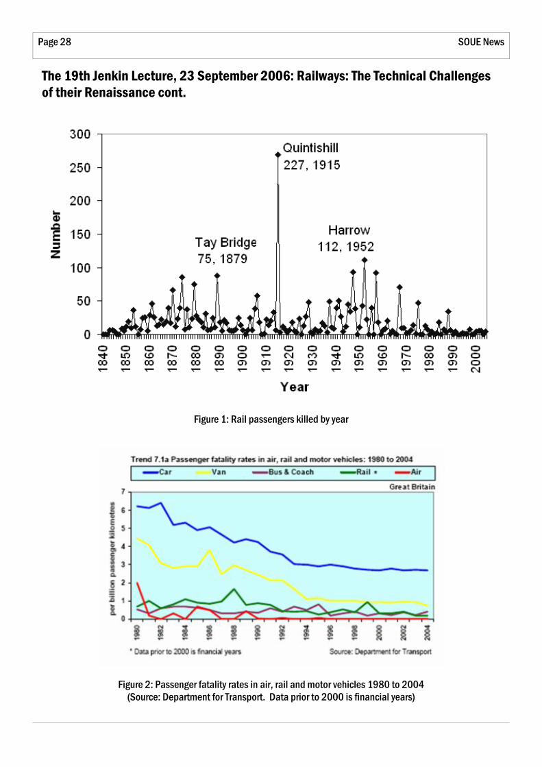
SOUE News Page 28
Figure 1: Rail passengers killed by year
Figure 2: Passenger fatality rates in air, rail and motor vehicles 1980 to 2004 (Source: Department for Transport. Data prior to 2000 is financial years)
The 19th Jenkin Lecture, 23 September 2006: Railways: The Technical Challenges of their Renaissance cont.

Page 29 Issue 6
with other modes of transport by showing passenger fatality rates per billion passenger kilometres since 1982. It is not clear whether this is the appropriate measure for comparison. For example, Table 1 implies that on this basis walking (or cycling) is 380 times more dangerous than flying. But there are not many journeys for which these are genuine alternatives. Perhaps expressing fatalities as per passenger hour, or per passenger journey, might give a more realistic comparison.
Mode of travel Fatalities/billion passenger km
Walk 38 Cycle 38 Car 2.7 Bus/coach 0.2 Rail 0.4 Air 0.1
Table 1 (data from DoT, Transport Trends 2005, #DoT, National Travel Survey 2005)
Dynamic Loads and Economics
The more perfect is the geometry of the railway track, the smoother will be the ride, which is clearly an attraction to the passengers. But fatigue damage to rails and wheels will also be reduced. High-speed trains require a more perfect track on both these grounds, but achieving that perfection, and maintaining it, can be very expensive. Reducing the weight of rolling-stock, and particularly of its unsprung mass (the bogies, wheels and axles) will reduce the fatigue damage caused by minor imperfections in the rail geometry, and hence the cost of maintenance. In the Japanese Shinkansen high-speed trains, the change from Series 100 to Series 300 went with a speed rise from 190 to 220 kph, but since both total and unsprung mass were reduced by some 25%, the rail maintenance cost actually went down by some 10%. The train mass per seat of the latest versions of this train is now down to about 550 kg. British trains are much heavier. For instance the Virgin Voyager and Pendolino are twice as heavy, at about 1100 kg per passenger seat. Table 2 shows mass/passenger for various "vehicles" (some of them
(Continued from page 27) obviously very approximate).
Vehicle Mass(kg)/passenger
Roller-skates 1 Bicycle 10 Double-decker bus 110 Family car 300 Stagecoach 400 747 aircraft 745 Queen Mary 2 58,000
Table 2: Vehicle masses per passenger
But it is interesting that the jumbo jet comes out as heavier than Japanese high-speed trains, but lighter than British ones. Part, at least, of the explanation is that from the way British Rail was privatised, there has been no economic incentive to design, or purchase, lighter rolling-stock. The trains are owned by one set of companies, and operated by another set, on track owned by Network Rail, who originally (but no longer) employed yet another set of companies to maintain it.
Fatigue Problems
Professor Smith went on to illustrate the disastrous consequences that could follow from ignoring fatigue damage. Rails wear out of shape, and develop cracks, as a result of rolling stock passing over them. Cracks propagate initially at a shallow angle of about 15° to the horizontal, to a depth of about 5–15 mm, but then turn down to a much steeper angle of about 70°, as shown in Figure 3 (overleaf). Rails therefore need to be reground periodically both to remove the cracked layer and to restore the proper profile on the upper surface (Figure 4). Railtrack and its contractors had neglected to do this, which resulted in a high-speed derailment at Hatfield on the main NE line in October 2000, when a heavily cracked rail broke into 300 pieces (Figure 5). In terms of its organisational and economic implications, this was perhaps the most traumatic and expensive accident in UK railway history.
In a similar German counterpart, an intercity express suffered a high-speed derailment
(Continued on page 30)

SOUE News Page 30
The 19th Jenkin Lecture, 23 September 2006: Railways: The Technical Challenges of their Renaissance cont.
Figure 3: Crack propagation in rails
Figure 4: Top: Position of contact in normal running Bottom: Movement to gauge corner produces higher
contact stresses
between Hanover and Hamburg in June 1998, resulting in 101 deaths. Here it was a tyre that broke, again through improper maintenance. The tyre was of a special type, separated from the hub by rubber pads to reduce the transmission of noise and vibration. So it was unsupported by the hub as far as bending stresses were concerned. Its radial thickness had been 64 mm at the start of its life. It had been re-profiled four times (without replacement), so reducing its thickness to 35 mm and trebling the stress in it. It then, after running some 1.8 million km in total, suffered a fatigue failure and came off (Figures 6 and 7).
(Continued from page 29)
Figure 5: Broken rail at Hatfield
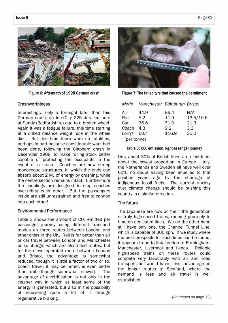
Page 31 Issue 6
Crashworthiness
Interestingly, only a fortnight later than this German crash, an InterCity 225 derailed here at Sandy (Bedfordshire) due to a broken wheel. Again it was a fatigue failure, this time starting at a drilled balance weight hole in the wheel disc. But this time there were no fatalities, perhaps in part because considerable work had been done, following the Clapham crash in December 1988, to make rolling stock better capable of protecting the occupants in the event of a crash. Coaches are now strong monocoque structures, in which the ends can absorb about 2 MJ of energy by crushing, while the centre section remains intact. Furthermore the couplings are designed to stop coaches over-riding each other. But the passengers inside are still unrestrained and free to cannon into each other!
Environmental Performance
Table 3 shows the amount of CO2 emitted per passenger journey using different transport modes on three routes between London and other cities in the UK. Rail is far better than air or car travel between London and Manchester or Edinburgh, which are electrified routes, but for the diesel-operated route between London and Bristol, the advantage is somewhat reduced, though it is still a factor of two or so. Coach travel, it may be noted, is even better than rail (though somewhat slower). The advantage of electrification is not only in the cleaner way in which at least some of the energy is generated, but also in the possibility of recovering quite a lot of it through regenerative braking.
Mode Manchester Edinburgh Bristol
Air 44.9 96.4 N/A Rail 5.2 11.9 13.5/10.6 Car 36.6 71.0 21.3 Coach 4.3 9.2 3.3 Lorry† 60.4 116.9 35.0 † (per tonne)
Table 3: CO2 emission, kg/passenger journey
Only about 30% of British lines are electrified, about the lowest proportion in Europe. Italy, the Netherlands and Sweden all have well over 60%, no doubt having been impelled to that position years ago by the shortage of indigenous fossil fuels. The current anxiety over climate change should be pushing this country in a similar direction.
The future
The Japanese are now on their fifth generation of truly high-speed trains, running precisely to time on dedicated lines. We on the other hand still have only one, the Channel Tunnel Line, which is capable of 300 kph. If we study where the best prospects for such lines can be found, it appears to be to link London to Birmingham, Manchester, Liverpool and Leeds. Reliable high-speed trains on these routes could compete very favourably with air and road transport, but would have less advantage on the longer routes to Scotland, where the demand is less and air travel is well established.
(Continued on page 32)
Figure 6: Aftermath of 1998 German crash Figure 7: The failed tyre that caused the derailment

SOUE News Page 32
The 19th Jenkin Lecture, 23 September 2006: Railways: The Technical Challenges of their Renaissance cont.
Dedicated lines are essential, since mixed traffic, if permitted, can cause substantial delays, for instance as occur on the main line from London to the NE, because of the single track in each direction on the Welwyn viaduct.
The final subject was electromagnetically levitated trains with linear motor drive, which were very topical on the day of the lecture, since a German version had had a bad crash on its experimental track the day before. It had collided at high speed with an engineer's
(Continued from page 31) vehicle which had unaccountably been left parked on the elevated track, resulting in 21 deaths. But it was not clear that this disaster cast any doubt on the feasibility or safety of such trains in normal operation.
For his final slide, Rod Smith showed us a cautionary quotation from Aldo Moro, late Prime Minister of Italy, that:
"There are two types of madmen: those who believe they are Napoleon and those who think they can sort out the railways."
Jet Engines, and Plastics
David Witt
The Jenkin Lecture was preceded by two half-hour "research talks".
In the first, David Gillespie told us about work on improving the efficiency of jet engines by reducing the leakage through the radial gap between turbine discs and the surrounding case. Any seal has to be capable of withstanding the high temperatures involved, and changes in the radial gap due to differential expansion, ovality and gyroscopic distortions. But a mere 1% reduction in specific fuel consumption would permit 15 extra passengers on a long-haul flight, and much larger reductions than this were conceivable.
A century ago, Charles Parsons devised the "labyrinth seal" for the shafts of his steam turbines, which works by creating a tortuous path that leaking gas has to find its way past. Research in Oxford had been started 15 years ago by Terry Jones, and had progressed first to the "bristle seal" (a sort of brush with alloy steel bristles) and then to the "leaf seal". This has a large number of thin metal leaves projecting from the circumference of the turbine wheel
and rubbing against a stationary ring. The leaves are straight in the axial direction, but bent into involute form in the plane of the turbine wheel. The latest version has proved very successful, less fatigue-prone than its predecessors. Samples were passed around for the audience to inspect.
In the second lecture, Paul Buckley talked about "The place of plastics in sustainable engineering". His aim was to defend plastics, or more specifically polymers, against the rather bad press they seem to have had recently. He pointed out that polymers need much less energy to create and form them than metals do, and although metals have some advantage over polymers where tensile strength and stiffness are concerned, the situation is reversed when one is more interested in their bending properties.
About 30% of polymer use is for packaging, and there has been a lot of progress here in "doing more with less". For instance, plastic bags used to be 50 µm thick, but are now made down to 10 µm, an advance which has required a lot of research. And we were invited to compare the weight of a PET bottle, e.g. for
Page 33 Issue 6
lemonade, of about 100 µm wall thickness, with that of its glass alternative. Some of the improvements in this area come from molecular alignment, achieved by forming components rapidly and then quenching them to stop re-alignment.
Better material properties can also be got by using composites. Some fibre-reinforced materials are familiar, but there are others less well-known. For instance, polypropylene,
reinforced with glass fibre, can withstand 100% strain. Fibres have a high surface-to-volume ratio, which gives them their strength, but then so do very small particles. Paul instanced Montmorillonite clay, which consists of platelets 10 Å (1 nm) thick, adhering to each other electrostatically. By adding 5% of this, the Young's Modulus of nylon-6 can be increased by 70%, which is better than can be got with glass fibres.
Sir Martin Wood, OBE, FRS, Hon.FREng, DL, Honorary President, Oxford Instruments Group plc — report by David Witt
Sir Martin began by recounting some experiences of his youth that had inspired his ambition to found his own company. He gave a light-hearted account of how, when working as a 15-year-old in an old-fashioned factory making farm machinery, he discovered that he could treble the productivity of a drilling machine by drilling holes in three pieces of wood at once. This merely aroused the resentment of the next man in the production line, who could no longer keep up, and won him neither praise nor a pay rise from the foreman. 5d per hour (=2p) was the limit for one of his age!
Then, under the "Bevin Boy" scheme, he spent his three years' National Service in a coal mine, where he was appalled by the confrontational attitudes between management and workforce. Did it have to be like this? Later, after six years of higher education, at Cambridge and Imperial College, he actually went back to the coal industry, now grossly over-qualified (graduates were then very rare in that field). But two years there convinced him that the evil of confrontation was irremediable, and he returned to Oxford.
Here he was offered a job in the Engineering
Department by Professor Alexander Thom, but the University declined to fund it, so Thom referred him to Professor Nicholas Kurti at the Clarendon, who did have some money. Kurti, a Hungarian Jew who had come here in the 1930s to escape the Nazis, had a low-temperature research group which needed very high and steady magnetic fields in small volumes, and it was Martin's job to produce the water-cooled magnets. These were powered by a 2 MW dc generator, giving up to 4500 A at 450 V, distributed around the building by uninsulated cables lying on the floor where people had to step over them. The dangers were obvious, and everyone was aware of them, so they never had any accidents! Cooling was by means of 100 tons of water in a tank on the roof.
There were regular visitors from other laboratories, keen on getting into similar low-temperature work themselves, whom Martin used to show around and advise about equipment etc. Some of them asked if he could produce magnets for them, since they were not available commercially, and the Clarendon agreed at first that they could be made in their own workshops. But after a bit there were complaints that this was getting in the way of jobs for their own people, so the arrangement had to end.
(Continued on page 34)
The 33rd Maurice Lubbock Memorial Lecture, 10 May 2007: The Entrepreneurial Bug

SOUE News Page 34
But the demand was still there, so Martin wondered whether he should set up a part-time business to manufacture them himself. Nicholas Kurti, far from raising any objection, exclaimed in his Hungarian accent "Vat can I do to help you?!", but did postulate that Martin should continue to work for him too for another ten years, which he did. Kurti was a quite remarkable man. In particular he showed great care and sensitivity towards all those who worked with him, a complete contrast to the confrontational attitudes Martin had come across previously.
In starting his company, which he named "Oxford Instruments" in emulation of its famous Cambridge counterpart, Martin had rather few of the things now regarded as essential in that situation. For instance, he had never heard of a "business plan". He needed little in the way of capital, since customers were happy to make substantial prepayments before their magnets were delivered. What capital he did need came from a bank loan secured on his house. Legal and accounting advice came from two brothers-in-law, and his wife Audrey revealed talents in all sorts of directions for which she had no paper qualifications whatever. In the light of which, Martin suggested that suitable advice to anyone starting a business might be "Marry the right girl!".
The magnets were made at home in the early years, first in the living-room, then in the coal-house, and then in a shed bought for the purpose. The neighbours had little idea of what was going on, nor did the Chairman of the Council Planning Committee, who lived just across the road! This was just as well, since in those days academic Oxford had a deep suspicion of industry. The motor works at Cowley had never been welcomed, and there had been some murky goings on even closer to home in the Owen affair of the 1930s.
Eventually it did become necessary to seek larger premises, and they found a disused slaughterhouse in Summertown, which the
(Continued from page 33) butcher was happy to let them use.
But about this time, a new discovery totally changed the nature of the business. Superconductivity had been known about since 1911, but hitherto all superconducting materials had lost this property when carrying significant currents or placed in a significant magnetic field. So they were no good for making the windings of electromagnets. But then at a conference in Cambridge, Massachusetts it was learnt that an alloy of niobium and zirconium had been found not to have these defects, and could be made into thin wire. The implications seemed truly profound.
Martin went home, ordered half a kilogram of this wire, and wound it into a magnet coil, with a lot of guesswork in the design. When cooled to a liquid helium temperature in the Clarendon, it suddenly went superconducting and generated a field of 4 tesla with a mere 20 A from a car battery. This was in April 1962. High-field magnets had been freed simultaneously from the need for large power sources to drive them, and for lots of water to get rid of the heat. This new discovery seemed to presage a revolution in electrical power engineering, and several companies tried to exploit it (BOC, Siemens, Toshiba and Phillips among the larger ones, and numerous smaller ones too). But for the majority of applications, the difficulties proved too great, and most of this activity came to nothing at the time. But in the production of magnets for scientific research, things were different. Oxford Instruments benefited greatly from the cryogenic know-how in the Clarendon, and soon got into a leading position, supplying superconducting magnets worldwide through the 60s and 70s. In retrospect they took enormous risks, but somehow everything prospered.
The company grew and grew, but in the process inevitably changed its nature from the small outfit it had been, where everybody knew everybody else. It became something of a role
The 33rd Maurice Lubbock Memorial Lecture, 10 May 2007: The Entrepreneurial Bug cont.

Page 35 Issue 6
model for spin-out activities, and in fact five other companies in succession used their Summertown premises for start-up. But the Woods became gradually less involved in running the firm. It went public in 1983, whereupon they had for the first time a significant amount of cash, with which they founded a charity known as the Oxford Trust. Its brief was to promote the application of science and technology, and started by helping local schools with science education, in the belief that this was fundamental to everything else. It then built a centre to house start-up companies, first in Osney Mead, then in Mill Street, but because such activity could not really be classed as "charitable", it was handed over to a company, Oxford Innovation, a wholly-owned subsidiary of the Oxford Trust, aimed at supplying accommodation and specialist services to small companies. This arrangement was acceptable to the Charity Commissioners.
The Trust then set up "Oxfordshire Investment Opportunity Network" as a sort of marriage bureau between small companies and "business angels" with money to invest. The sums invested were frequently not small at all, ranging up to £1 million or more, and there seemed to be a need for something to offer smaller sums to those who were really only just starting, and "Oxford Early Investment" was the result.
The result of all this was that by means of intell igent, technically well- informed networking, Martin claimed that the Oxford Trust had made a real change to the industrial infrastructure in Oxfordshire (and Cambridgeshire too). And of course spin-out companies from the local Universities were now a common phenomenon.
This concluded the main part of the lecture, but there was still time to demonstrate some technical achievements.
1. Around 1952, the lowest temperature that had been achieved was about 0.25 K, by vigorous pumping with 3He. It had later been suggested that since 4He was "superfluid" at these temperatures, a layer of 3He diffusing into it would effectively be evaporating, so it might be
possible to get still lower temperatures that way. The Atomic Energy Authority wanted to place a contract for the development of apparatus for this purpose, and Oxford Instruments won the contract, in competition with Phillips of Eindhoven and Arthur D Little of Cambridge Massachusetts. The apparatus was very difficult to develop, and quite complicated to use, but they did make several for various favoured customers, and two such were on display. Martin also showed a modern version of it, more compact, self-contained and easier to operate, which can be made as a standard product. It can reach 0.02 K, and is bought by people working on quantum computing.
2. We were then given a demonstration of high-temperature superconductors, that work at liquid nitrogen temperatures, around 75 K as opposed to ~4 K for the niobium-titanium and niobium-tin alloys used by Oxford Instruments' magnets. These new materials came into prominence in 1997, and their prospects were hyped in the same way as the earlier materials had been 35 years earlier, but the enthusiasm had faded again. However they undoubtedly work, and if only they can be formed into wires, will have great scope in electrical engineering. An early use could be in ship propulsion. For the demonstration Martin cooled several pieces of an yttrium-barium-copper-oxide alloy by pouring liquid nitrogen over them, whereupon a permanent magnet floated spinning over them, suspended by the non-decaying eddy-currents, to the general applause of the audience.
A film of the full lecture can be seen on the Department's web site, www.eng.ox.ac.uk/events. It brings out its entertainment value better than this written synopsis can do.

SOUE News Page 36
Project Exhibition 2007
David Witt
This year we again have to thank our sponsors, Sharp of Europe, Atkins, GlaxoSmithKline and QinetiQ for contributing £3000 of prize money between them, which enabled us to offer some worthwhile prizes. SOUE chipped in with a modest £200 (and the organisation). We had 24 entries, slightly less than the 29 last year, and everything fitted into LR3 (just), except for one (Michael Smith) which needed a projector and lots of space to view it, in LR2.
The £500 Sharp prize for an electronic exhibit went to Martin Evans of St John's for "Solar Sheep", which in fact is an autonomous lawnmower. An earlier stage of this had been exhibited last year, but Martin had made some interesting improvements to the infra-red navigation system.
The £500 Atkins prize for a civil/structural exhibit was awarded to Ed Crammond of Corpus for "Arbitrarily shaped particles in distinct element analysis". Put like that, it sounds a bit tedious, but his computer-
generated display of oddly shaped bits somehow finding suitable places to tuck themselves into as they fell to the bottom of a bin was fascinating, anything but tedious.
The £400 QinetiQ prize for an "exhibit working towards an innovative solution of an important problem" went to Mike Wallace of Keble for "Product Design: a novel emergency drinking-water device", which used membranes and some clever chemical engineering to turn polluted water into something that could safely be drunk in emergencies.
Other prizes were awarded as follows:
For technical contribution
£250 to Alasdair Bell, Queens, for "Design of a hybrid rocket for satellite orbit injection", and
£250 to Nauman Shah, Exeter, for "Modelling multi-mode optical fibre networks"
For a good exhibit involving hardware
£200 to Michael Smith, Wadham, for "Prototype of a commercial system — reality racer"
For a good poster exhibit
£200 to Ned Gould, Christ Church, for "Offshore oil pipeline unburial"
For a materials exhibit
£200 to Felix Hofman, Trinity, for "Analysis of temporal and spatial temperature field

Page 37 Issue 6
evolution in metallic specimens"
For a historical study
£200 to Lucy Thomas, St John's, for "Stephenson's Britannia Bridge — an early box girder"
Commended
£100 to Charlie Briggs, Oriel, for "Electromagnetic detection of buried pipes"
£100 to Richard Harrap, Exeter, for "Environmental impacts of the Zenon and Kubota membranes for waste-water treatment"
£100 to Joshua Macabuag, Pembroke, for "Modelling and retro-fitting of non-engineered masonry under seismic loading"
£100 to Hugo Pillath, New College, for "Plywood reinforcement of timber gridshells"
£100 to Oliver Whyte, Wadham, for "Restoration and colourisation of video"
And there were several other very interesting exhibits as well.
The hard-working judges, to whom we are very grateful, were:
Mike Brownlow, Univ 1985–8, now with Sharp of Europe
Graham Hawkes, St Catherine's 1997–2001, now with Frazer-Nash
Gill Smith, Oriel 1996–2000, now with Atkins
Jonathan Snell, St John's 1998–2002, now with Instron
Finals and Prelims Prizes Awarded 2007
The Examiners recommended the following awards in respect of Final Honour Schools in 2007:
Engineering Science, Part 2
Maurice Lubbock Prize for best performance:
Jonathan M Gartside, Balliol
Edgell Sheppee Prize for excellent perform-ance:
Christopher D Pritchard, Oriel
Head of Department's Prize for excellent performance Thomas J Kember, Christ Church and Peter W Brice, St Edmund Hall
ICE Prize for best performance in civil engineering:
Michael J Graham, Worcester
IMechE nomination to the Frederic Barnes Waldron Prize:
Felix Hofmann, Trinity
IMechE Best Student Certificate
Christopher J Burgess, Christ Church
IET Prize for outstanding academic achievement:
Alexander C Bennett, Hertford
IET Manufacturing Engineering Prize:
Richard J Good, St Edmund Hall
IChemE Prize for best performance in chemical engineering:
Michael H Braisher, Keble
Best performance in biomedical engineering:
Adam J Davidson, Exeter
Babtie Prize for the best projects in civil engineering: Adri Kerciku, Balliol and Lucy V Thomas, St John's
(Continued on page 38)
SOUE News Page 38
Finals and Prelims Prizes Awarded 2007 cont.
IMechE Prize for the best project in mechanical engineering:
Philip D Siddorn, Brasenose
IMechE Certificate for an outstanding project in mechanical engineering:
Alex P Graham, Oriel
Motz Prize for best project in electrical engineering:
William E Treharne, Balliol
Ronald Victor Jansen Prize for best project in electronic communications:
Nauman Shah, Exeter
Worshipful Company of Scientific Instrument Makers Project Prize:
Alexy D Karenowska, Magdalen
HMGCC Project Prize in information engineering
Oliver A Whyte, Wadham
An outstanding project in biomedical engineering:
Mark G Catherall, University
Royal Academy of Engineering Prize for excellent design in a fourth-year project:
Ross A McAdam, Keble
Rolls-Royce prize for an outstanding project displaying innovation:
Emma F Cox, St John's
Engineering Economics and Manage-ment, Part 2
Maurice Lubbock Prize for best performance:
Karin M Mueller, Balliol
Edgell Sheppee prize for best performance in an engineering project:
Peter H Nordberg, Magdalen
(Continued from page 37) Engineering and Computer Science, Part 2
Maurice Lubbock Prize for best performance:
Andrew J Knight, St John's
Engineering Science, EEM and ECS Part 1
Edgell Sheppee prize for laboratory or drawing office work:
Nicholas P Hucker, Keble
Gibbs Prize for best Part 1 project, jointly to: Elizabeth S Bush, Wadham; Laura C Noiret, Brasenose; Toby R Normanton, Exeter; Akanat Promphan, St Anne's
Royal Academy of Engineering Prize for best treatment of sustainability in a project, jointly to:
Jemima C Boardman, St Hilda's; Ching H Chan, St Hugh's; Edward SV Digby, St Hugh's; Stuart M Hookham, Oriel; Samuel S Jones, Magdalen; David P O'Neill, University
The Moderators recommended the following awards in respect of the Preliminary Examination
Crown Packaging UK plc Prize for best perform-ance:
Zeng Wang, St John's
Shell prize for outstanding performance:
Benjamin W Kirollos, University
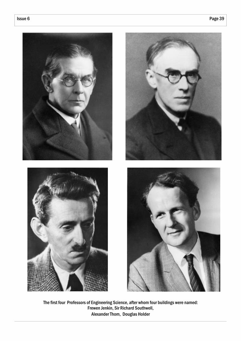
Page 39 Issue 6
The first four Professors of Engineering Science, after whom four buildings were named: Frewen Jenkin, Sir Richard Southwell,
Alexander Thom, Douglas Holder

SOUE News
Society of Oxford University Engineers Department of Engineering Science University of Oxford Parks Road Oxford OX1 3PJ
E-mail: [email protected]
Copyright © 2007 Society of Oxford University Engineers
Visit our website:
www.soue.org.uk
The Thom Building nearing the end of its construction
Produced by David Witt (Magdalen 1959) and Simon Turner (Lincoln 1984) Printed by Holywell Press