jet eng
DESCRIPTION
jet enggTRANSCRIPT

254 IEEE TRANSACTIONS ON CONTROL SYSTEMS TECHNOLOGY, VOL. 21, NO. 1, JANUARY 2013
A Multiple Model-Based Approach for Fault Diagnosis of Jet EnginesN. Meskin, E. Naderi, and K. Khorasani
Abstract—In this brief, a novel real-time fault detection and iso-lation (FDI) scheme that is based on the concept of multiple modelis proposed for aircraft jet engines. A modular and a hierarchicalarchitecture is developed which enables the detection and isola-tion of both single faults as well as multiple concurrent faults inthe jet engine. The nonlinear dynamics of a dual spool jet engineis linearized and a set of linear models corresponding to variousoperating modes of the jet engine (namely healthy and differentfaulty modes) at each operating point is obtained. Using the mul-tiple model approach the probabilities corresponding to each op-erating point of the jet engine are generated and the current oper-ating mode of the system is detected based on evaluating the max-imum probability criteria. It is shown that the proposed method-ology is also robust to the failure of pressure and temperature sen-sors and extensive levels of noise outliers in the sensor measure-ments. Simulation results are presented that demonstrate the ef-fectiveness and capabilities of our proposed multiple model FDIalgorithm for both structural faults and an actuator fault in theaircraft jet engine.
Index Terms—Aircraft jet engines, fault diagnosis, Kalman fil-ters, multiple model-based FDI approach, robustness analysis.
I. INTRODUCTION
T HE increasing complexity of aerospace systems, such asjet engines, and the cost reduction measures that have af-
fected aircraft and engine manufacturers and maintenance oper-ators, are increasingly driving the need for more intelligence andautonomy capabilities and functionalities for diagnosis, prog-nosis, and health management (DPHM) of these safety criticalsystems. The objective of an aircraft engine DPHM system isto provide monitoring, predictive trend analysis, diagnosis offaults and degradations. Increased design complexity, strict se-curity and safety requirements, and the need for reduction ofthe life cycle cost make it necessary to move forward fromconventional simple statistical trend analysis and monitoringpractices towards an integrated DPHM system that can bothautonomously and in real-time interact with human experts inorder to address the above-mentioned issues.In the past few decades, several fault diagnosis approaches
have been investigated in the literature. Gas path analysis (GPA)[1]–[3] is one of the most popular diagnostic procedures whichrelies on discernible changes in the observable parameters of
Manuscript received April 27, 2011; revised September 14, 2011; acceptedNovember 18, 2011. Manuscript received in final form November 22, 2011.Date of publication December 30, 2011; date of current version December 14,2012. Recommended by Associate Editor A. Alessandri. This work was sup-ported in part by a grant from the Natural Sciences and Engineering ResearchCouncil of Canada (NSERC) under the industrial Collaborative Research andDevelopment (CRD) Partnership Program.N.Meskin is with the Department of Electrical Engineering, Qatar University,
Doha, Qatar.E. Naderi and K. Khorasani are with the Department of Electrical and Com-
puter Engineering, Concordia University, Montreal, QC H3G 1M8, Canada(e-mail: [email protected]).Digital Object Identifier 10.1109/TCST.2011.2177981
the engine to detect presence of faults. Common faults consistof combinations of anomalies and factors such as foreign ob-ject damage (FOD), blade erosion and corrosion, worn seals,excess clearances, or plugged nozzles. These attributes resultin changes in the thermodynamic performance of the jet engineas measured by adiabatic efficiencies, compressor flow capaci-ties and effective nozzle areas, etc. [4]. A large number of ap-proaches such as Kalman filtering [5]–[7], neural networks [8],and hybrid diagnosis [9] have been reported in the literature forfault diagnosis using GPA.Previous work on the application of a bank of filters for fault
diagnosis of jet engines [6], [7] have focused on sensors and ac-tuators fault detection and isolation (FDI). In these approaches,an augmented state space model of the jet engine is used forFDI where the so-called “health parameters” are included in thestate vector of the system. A bank of filters is then designed forthe augmented state space model. As explicitly stated in [6], dueto the observability constraint on the augmented system, not allthe health parameters can be included in the augmented system,and hence some of the health parameters cannot be estimated.As shown in [6], degradations in the health parameters that arenot estimated can subsequently lead to false alarms in the resid-uals.In this brief, a multiple model (MM)-based scheme is pro-
posed and developed for fault diagnosis of aircraft jet engines.The benefit and advantage of our approach is that all the healthparameters are considered for performing the FDI, and more-over one can detect degradations in all the health parametersas well as faults in the actuators. Finally, our proposed hierar-chical architecture enables one to detect the presence of con-current faults resulting from structural and actuator anomalies.A preliminary version of these results has already appeared in[10].In the proposed MM-based fault diagnosis approach it is as-
sumed that at each operating point of the jet engine, its dynamicsis adequately represented by a linear model that is parameterizedby a fault vector. It is further assumed that the fault vector cantake on only discrete values corresponding to the normal andvarious failure modes in the jet engine. The linear model corre-sponding to each fault vector around an operating point of the jetengine is obtained from a fully nonlinear model of the system.A bank of Kalman filters is then designed where each Kalmanfilter corresponds to and is associated with a specific value of thefault vector. The conditioned probabilities of each discrete pa-rameter value being the correct one, given the measurement his-tory are calculated iteratively by using the Bayes’ law. The cur-rent operating mode of the jet engine is then determined basedon the maximum probability criteria. Moreover, a hierarchicalapproach is proposed where multiple levels of detection filtersare designed that according to the current jet engine operatingpoint [power level angle (PLA)] and the jet engine status op-erating mode (that is healthy or faulty), only an appropriate set
1063-6536/$26.00 © 2011 IEEE

MESKIN et al.: MULTIPLE MODEL-BASED APPROACH FOR FAULT DIAGNOSIS OF JET ENGINES 255
of bank of filters is active at any given time. This hierarchicalarchitecture enables the detection and isolation of concurrentfaults in the jet engine without adding any extra computationalload as compared to the case of a single FDI problem.Further advantages of our proposed approach over other
FDI techniques are motivated and justified according to thefollowing two observations. First, the probabilistic MM-basedapproach efficiently addresses the critical issue of thresholdselection and evaluation (with respect to the generated residualerror signals), a problem that is quite difficult to robustly solvein other standard FDI methods. Specifically, in these methodsin order to determine a threshold, extensive set of simulationsand evaluations are required, despite which the designer usuallyends up with a tradeoff between the number of false alarms andthe number of missed detections. The lower the threshold isselected, the larger the number of false alarms (false positive).On the other hand, the higher the threshold is selected fewernumber of false alarms are flagged, but it may then not bepossible to detect low severity faults (false negative). Second,the FDI logic that is designed based on residual thresholdsis in general quite complex, specially in the case of multiplefaults where one requires a sophisticated interpreter to analyzethe corresponding residual signals and the thresholds. Theselimitations and drawbacks are not present in the probabilisticMM-based FDI approach that is developed in this work. Asshown subsequently, the logic is quite simple and the interpre-tations of the results are quite straightforward.The performance of the MM-based algorithm under three dif-
ferent sets of measurements (or sensor installations) is inves-tigated, namely, 1) temperature, pressure, and rotational speedmeasurements; 2) pressure and rotational speed measurements;and 3) rotational speed measurements. It is shown that our pro-posed fault diagnosis scheme can detect and isolate all the faultsthat are considered by utilizing any of the above measurementsets with the only resulting impact being that the fault detectiontimes become longer when a fewer number of measurement sen-sors are used.The above clearly demonstrates one of the main advantages
of our proposed fault diagnosis scheme that despite the im-plementation of possibly different sensor installations, avail-abilities or the presence of total failure of some sensors, suchas temperature and pressure, the fault diagnosis algorithm canstill operate properly in detecting and isolating faults by usingonly the rotational speed measurements. Finally, the effects ofsensor noise measurement outliers on the performance of theMM-based fault diagnosis scheme are also investigated. It isdemonstrated that our proposed algorithm is robust to signifi-cant measurement noise outliers.The remainder of this brief is organized as follows. In
Section II, a brief overview of the MM approach is presented.A nonlinear mathematical model of a jet engine that is con-sidered for design and testing of the MM-based approach forFDI is developed in Section III. In Section IV, the MM-basedFDI methodology is proposed and developed for a jet engine.In Section V, simulation results corresponding to differentfault scenarios in the jet engine are presented. Conclusions andfuture work are presented in Section VI.
II. MM-BASED FDI ALGORITHM
In this section, a brief overview of the MM-based FDI algo-rithm is presented [11]. Let denote the vector of fault parame-ters in a given dynamical system where it can take on only oneof the representative values . The modelcorresponding to is described by the discrete-time system
(1)
where is the state of the system, is the measurementvector, and is the control input vector. The fault parametermay correspond to the actuator, the sensor or the structural
faults. In this work the parameter corresponds to the healthymode of the jet engine, correspond to common jetengine component faults, and corresponds to the fuel flowvalve fault. The process and the measurement vectors andare mutually independent white Gaussian noise of zero meanand covariances and , respectively.Let the hypothesis conditional probability be defined as
the probability that assumes the value (for ),conditioned on the observed measurement history up to time ,that is
(2)
where the measurement history random vector is madeup of the partitions that represent the availablemeasurements up to the th sample time and similarly, the re-alization of the measurement history vector has partitions
[11]. It can be shown that can be evaluated re-cursively for all via the iteration [12]
(3)
in terms of the previous values of ,and conditional probability densities for the current measure-ment (denoted by ). For fur-ther information on the stability and convergence properties andanalysis of the MM-based FDI approach the reader can refer to[13] and [14].TheMM-based FDI scheme is now composed of a bank of
individual and separate Kalman filters, each based on a partic-ular value of . More explicitly, based on model(1), the th Kalman filter, , is specified by the pre-diction step according to:
,and the measurement update step according to:
, and . The innovationvector is used to compute via (3) witha Gaussian density function given by
(4)
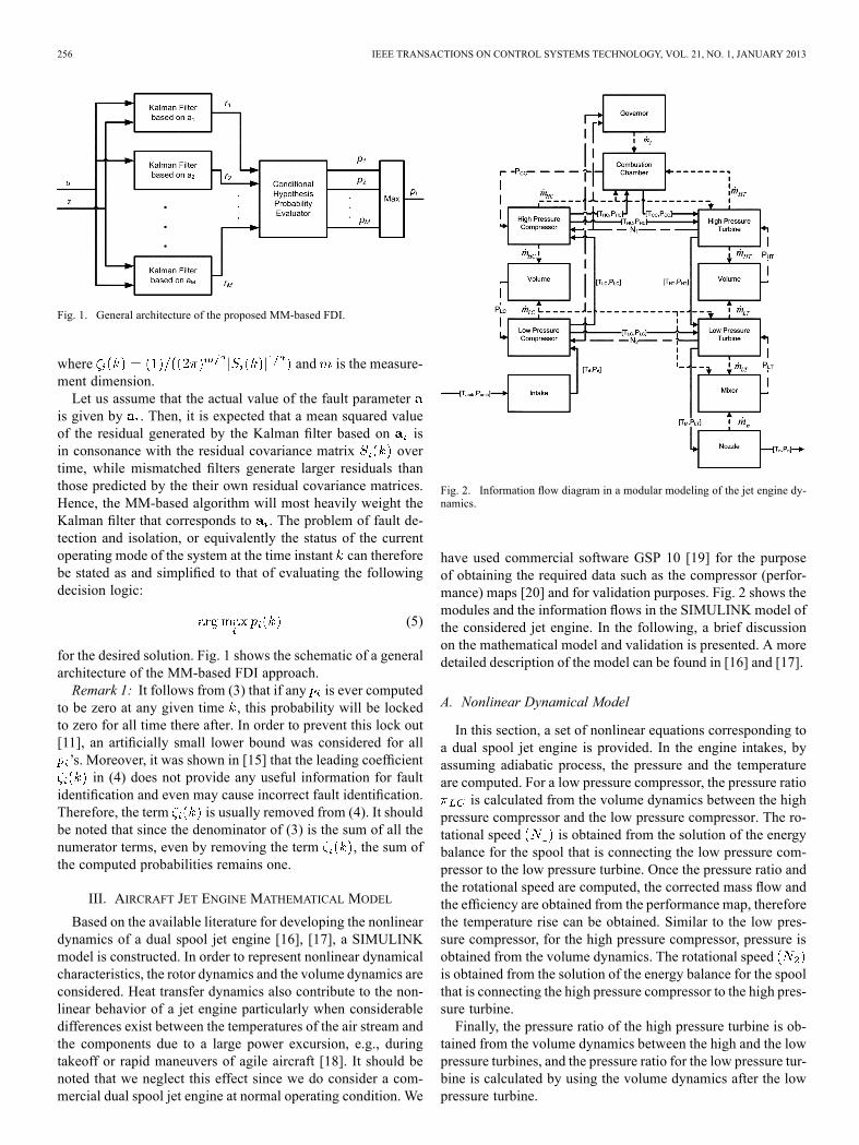
256 IEEE TRANSACTIONS ON CONTROL SYSTEMS TECHNOLOGY, VOL. 21, NO. 1, JANUARY 2013
Fig. 1. General architecture of the proposed MM-based FDI.
where and is the measure-ment dimension.Let us assume that the actual value of the fault parameter
is given by . Then, it is expected that a mean squared valueof the residual generated by the Kalman filter based on isin consonance with the residual covariance matrix overtime, while mismatched filters generate larger residuals thanthose predicted by the their own residual covariance matrices.Hence, the MM-based algorithm will most heavily weight theKalman filter that corresponds to . The problem of fault de-tection and isolation, or equivalently the status of the currentoperating mode of the system at the time instant can thereforebe stated as and simplified to that of evaluating the followingdecision logic:
(5)
for the desired solution. Fig. 1 shows the schematic of a generalarchitecture of the MM-based FDI approach.Remark 1: It follows from (3) that if any is ever computed
to be zero at any given time , this probability will be lockedto zero for all time there after. In order to prevent this lock out[11], an artificially small lower bound was considered for all’s. Moreover, it was shown in [15] that the leading coefficient
in (4) does not provide any useful information for faultidentification and even may cause incorrect fault identification.Therefore, the term is usually removed from (4). It shouldbe noted that since the denominator of (3) is the sum of all thenumerator terms, even by removing the term , the sum ofthe computed probabilities remains one.
III. AIRCRAFT JET ENGINE MATHEMATICAL MODEL
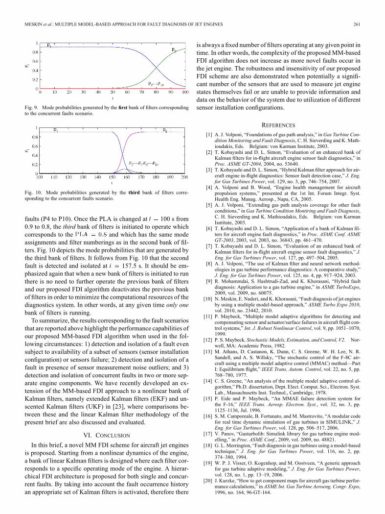
Based on the available literature for developing the nonlineardynamics of a dual spool jet engine [16], [17], a SIMULINKmodel is constructed. In order to represent nonlinear dynamicalcharacteristics, the rotor dynamics and the volume dynamics areconsidered. Heat transfer dynamics also contribute to the non-linear behavior of a jet engine particularly when considerabledifferences exist between the temperatures of the air stream andthe components due to a large power excursion, e.g., duringtakeoff or rapid maneuvers of agile aircraft [18]. It should benoted that we neglect this effect since we do consider a com-mercial dual spool jet engine at normal operating condition. We
Fig. 2. Information flow diagram in a modular modeling of the jet engine dy-namics.
have used commercial software GSP 10 [19] for the purposeof obtaining the required data such as the compressor (perfor-mance) maps [20] and for validation purposes. Fig. 2 shows themodules and the information flows in the SIMULINK model ofthe considered jet engine. In the following, a brief discussionon the mathematical model and validation is presented. A moredetailed description of the model can be found in [16] and [17].
A. Nonlinear Dynamical Model
In this section, a set of nonlinear equations corresponding toa dual spool jet engine is provided. In the engine intakes, byassuming adiabatic process, the pressure and the temperatureare computed. For a low pressure compressor, the pressure ratio
is calculated from the volume dynamics between the highpressure compressor and the low pressure compressor. The ro-tational speed is obtained from the solution of the energybalance for the spool that is connecting the low pressure com-pressor to the low pressure turbine. Once the pressure ratio andthe rotational speed are computed, the corrected mass flow andthe efficiency are obtained from the performance map, thereforethe temperature rise can be obtained. Similar to the low pres-sure compressor, for the high pressure compressor, pressure isobtained from the volume dynamics. The rotational speedis obtained from the solution of the energy balance for the spoolthat is connecting the high pressure compressor to the high pres-sure turbine.Finally, the pressure ratio of the high pressure turbine is ob-
tained from the volume dynamics between the high and the lowpressure turbines, and the pressure ratio for the low pressure tur-bine is calculated by using the volume dynamics after the lowpressure turbine.

MESKIN et al.: MULTIPLE MODEL-BASED APPROACH FOR FAULT DIAGNOSIS OF JET ENGINES 257
To summarize, the nonlinear set of governing equations ofmotion for a dual spool jet engine can be described as follows:
(6)
where , and denote the com-bustion chamber, low pressure compressor, high pressure com-pressor, low pressure turbine, high pressure turbine and mixertemperatures, respectively, , anddenote the combustion chamber, low pressure compressor, highpressure compressor, low pressure turbine and high pressureturbine pressures, respectively, denote thevolume of gas inside mixer, combustion chamber, low pressurecompressor, and high pressure turbine, respectively, anddenote the rotational speed of the spool connecting the highpressure compressor to the high pressure turbine and the spoolconnecting the low pressure compressor to the low pressure tur-bine, respectively, is the mass flow in different components,
and denote the mechanical efficiencies, anddenote the inertia of the low and the high pressure shafts, re-spectively, denotes the mass of air inside the combustionchamber, denotes the combustion chamber efficiency, de-notes the bypass ratio, denotes the heat capacity ratio, de-notes the gas constant, denotes the heat at constant volume,denotes the specific heat at constant pressure, and denotes
the fuel specific heat. We also adopt from [16] the following todescribe the fuel mass flow rate:
(7)
where is the time constant, is the gain, and is thefuel demand that is computed by using a feedback from therotational speed as described in [16]. The state variables andthe output measurement in the dual-spool jet engine are se-lected as , and
.
B. Validation
A series of steady-state responses are obtained and reportedin [10] using our model (6) and the GSP at PLAs ranging from0.4 to 1. At each point, the initial condition is set to the PLAequal to 0.3 followed by a transient to reach to the steady statecorresponding to the desired PLA. Since the steady state corre-sponding to each PLA is independent of the path taken during
TABLE IDEFINITIONS OF THE CONSIDERED COMPONENT FAULTS
the transient (unless the compressor surges), it provides a suit-able basis for comparison. We have concluded (figures are notshown due to space limitations and can be found in [10]) that theresponses match each other within an acceptable error (below5%). The difference comes from the fact that we have useda simplified model in comparison with the more complicatedstructure of the GSP [19]. Moreover, transient responses ob-tained from our model for different scenarios were in agree-ment with the GSP results which demonstrate that our model isvalid for simulation of nonlinear dynamics of the jet engine. TheGSP software does not provide an interface with the MATLAB/Simulink, and therefore the FDI algorithm cannot be directly ap-plied and implemented in the GSP environment. For this reason,and in order to validate the model that is used in this brief forFDI, as indicated above we compared in [10] the simulation re-sults of the nonlinear dynamics of the gas turbine developed inthe MATLAB/Simulink with the simulation results that are ob-tained from the GSP software.
IV. MM-BASED FAULT DIAGNOSIS DESIGN
In this section, a fault diagnosis algorithm for a dual spool jetengine based on the MM methodology is developed. Towardsthis end, first the jet engine model is linearized around variousoperating points so that linear fault models corresponding toeach operating mode is derived. Finally, MM-based “linear” fil-ters are designed according to the procedure that is detailed inSection II. A number of discrete-time linear models for variousoperating points of the jet engine are obtained associated withthe nonlinear model (6) having a sampling period of 0.01 s.
A. Fault Modeling and Detection Filter Design
In this brief, both component as well as actuator anomaliesare considered as sources of faults. Common component faults[1] are modeled as changes in the component efficiency andflow capacity. Eight component faults are investigated in thiswork as shown in Table I. Moreover, a fault in the fuel valveis considered as an actuator fault. Hence, the total number ofoperating modes corresponding to each operating point of thejet engine (as defined for a fixed PLA) is ten where mode #1(P1) corresponds to the healthy jet engine, modes #2 to #9 (P2 toP9) correspond to the component faults as shown in Table I, andmode #10 (P10) corresponds to the loss of effectiveness fault inthe fuel valve actuator (7).Operating points of the jet engine are classified in terms of
the PLA control input. At each PLA, ten linear models corre-sponding to the healthy and faulty operational modes are ob-tained. Faulty models corresponding to the component faults in

258 IEEE TRANSACTIONS ON CONTROL SYSTEMS TECHNOLOGY, VOL. 21, NO. 1, JANUARY 2013
Fig. 3. Hierarchical multiple model architecture corresponding to two levelsassociated with the FDI of two concurrent faults. The methodology can be ex-tended without any difficulty to third and higher levels in principle representingthe occurrence of three and more concurrent faults.
TABLE IIOPERATING MODES CORRESPONDING TO VARIOUS POSSIBLE TWO
CONCURRENT FAULTS SCENARIOS
Table I are obtained by considering a 2% decrease in the effi-ciency or the flow capacity with respect to the normal mode.For instance for obtaining the linear model associated with theoperating mode #3, the low pressure compressor efficiency isdecreased by 2% [5], [21]. Moreover, the linear model associ-ated with the operating mode #10 (actuator fault mode) is ob-tained by considering a 5% loss of effectiveness in the gainin the fuel actuator valve model (7).For detection and isolation of two concurrent faults in the jet
engine, a hierarchical approach is proposed [11] as shown inFig. 3 and Table II. In the proposed approach, it is assumed thatthe jet engine starts from the healthy condition when the “firstlevel” of filters are active and the proposed algorithm observesthe engine for occurrence of one of the nine faults that are spec-ified above. As depicted in Fig. 3, the active bank of filters de-pends on the current PLA. In other words, as the PLA changes,the bank of filters corresponding to the new PLA is activated andthe previous bank is deactivated. Since our scheme is developedbased on linear models to estimate the nonlinear behavior of thejet engine, if the engine operates far from the PLA at which it islinearized, the difference between the linear model and the ac-tual engine will widen which could lead to false alarms in cer-tain cases. Therefore, a range should be determined about eachoperating point corresponding to the PLA in which the linearmodels as well as the corresponding bank of filters remain validfor the purpose of FDI.
TABLE IIIFAULT DETECTION AND ISOLATION PERFORMANCE OF A BANK OF FILTERSTHAT IS DESIGNED FOR BUT APPLIED TO OTHER PLAS.LEGEND: “ ” DESIGNATES THE OCCURRENCE OF A FALSE ALARM
AND “ ” DESIGNATES THE CORRECT FDI
In order to accomplish the above goal, for each fault mode,the validity of the bank of filters for a 20% deviation fromthe operating point is examined through simulations. Table IIIdepicts the fault detection and isolation performance of the de-signed bank of filters corresponding to the PLA of 0.9 that aretested subsequently at different PLA levels. In this table, “ ”designates that the corresponding operating mode of the en-gine is detected and isolated successfully and “ ” designates theoccurrence of a false alarm. As can be seen clearly, the bankof filters corresponding to the PLA of 0.9 is valid for use inthe 5% deviations from the given operating point. In fact,it turns out by simulations that this margin also provides sat-isfactory results for the other values of PLAs from 0.4 to 1.Consequently, six PLA levels are selected here ranging from
to with a 0.1 step between each level(i.e., ). For instance, the bank of filtersdesigned for the is used for fault diagnosis corre-sponding to the range of and if the PLAbecomes higher than 0.55, the bank of filters corresponding to
will become active for the purpose of performingthe FDI. In this manner, the FDI algorithm can distinguish be-tween a change in the operating point and the occurrence of afault in the jet engine.Once the first fault is detected and isolated according to
the maximum probability criteria (5) that is described inSection II, the FDI algorithm will activate the “second level”of filters (shown in Table II) for detection and isolation ofthe second concurrent fault. It should be noted that in ourproposed hierarchical architecture, it is assumed that faultsdo not occur simultaneously and there exists a minimum timeinterval between the occurrence of faults. In other words, weare considering and allowing the occurrence of concurrentfaults. Table II depicts all the possible configurations for thesecond bank of filters. For example, if the first fault is detectedas a 2% change in the low pressure compressor flow capacity(P2) (depicted in Fig. 3 corresponding to the ),then the first filter in the second level corresponds to the de-tected fault scenario (P2) (that is, %), the secondfilter corresponds to a further decrease of (3%) in the lowpressure compressor flow capacity resulting in a total of 5%decrease in the capacity (that is, %), the thirdfilter corresponds to the concurrent decrease of 2% in the lowpressure compressor flow capacity and a decrease of 2% in

MESKIN et al.: MULTIPLE MODEL-BASED APPROACH FOR FAULT DIAGNOSIS OF JET ENGINES 259
the low pressure compressor efficiency (P2 and P3) (that is,% and %), etc. As another illustration,
if the first fault is detected as a 5% loss of effectiveness orgain in the fuel actuator valve (P10) (that is, % asdepicted in Fig. 3 corresponding to the ), then thefirst filter in the second level corresponds to the detected faultscenario (P10), the second filter corresponds to the loss of thegain in the fuel actuator valve and a decrease of 2% in the lowpressure compressor (P10 and P2) (that is, % and
%), etc. Note that this procedure can be similarlyextended to the third and higher levels corresponding to theoccurrence of multiple (three and more) concurrent faults.It should be emphasized that when the new bank of filters is
activated in the second level, there is no need to further operatethe first bank of filters and the proposed FDI algorithm deacti-vates this bank of filters to save the diagnostic system’s com-putational load. In other words, the hierarchical architecture en-ables one to detect and isolate the occurrence of the second faultwithout adding any computational burden since at any giventime, only 10 filters are operating online.Remark 2: Note that in the above hierarchical fault diagnosis
architecture, only two levels of fault severities, namely 2% and5% are considered as an illustration. It should be emphasizedthat more fault severities can equally and easily be consideredby correspondingly increasing the number of models that areconsidered in this architecture.
V. SIMULATION RESULTS
In this section, simulation results and performance evalua-tions of different fault scenarios are presented. The robustnessand sensitivity of the MM-based FDI scheme detection timessubject to the availability of partial sensors or failures ina number of sensors are evaluated. It should be noted thatall faults are actually applied to and injected into the fullynonlinear model of the jet engine. However, our proposed hi-erarchical MM-based FDI algorithm is developed and is basedon the linearized model of the jet engine. The measurementnoise levels are selected similar to those reported in [21]. It isalso assumed that the and the ambient conditionsare set to standard conditions and the Mach number is 0.74.The parameters corresponding to the model (6) are selected asfollows: 7.04 kg m 5.69 kg m 0.45 m
0.2 m 0.1 m 0.2 mkg
288 K (ambient temperature), 1 Pascal (ambientpressure), kg K
kg K , and kg K .
A. Single Fault Scenario
Figs. 4 and 5 show the mode probabilities and the output mea-surements corresponding to the injected 2% decrease in the lowpressure compressor efficiency that is applied at 5 s (Mode#3), respectively. According to Fig. 5, after the injection of thefault the output measurements have changed as follows: 0.27%increase in , 0.7% decrease in , 0.7% increase in ,0.6% increase in , 0.3% increase in , and negligiblechanges in , and . As shown in Fig. 4, for all
Fig. 4. Mode probabilities corresponding to the injected 2% decrease in thelow pressure compressor efficiency that is applied at 5 s (Mode #3).
Fig. 5. Output measurements corresponding to the injected 2% decrease in thelow pressure compressor efficiency that is applied at 5 s (Mode #3).
Fig. 6. Mode probabilities corresponding to the injected 2% decrease in thelow pressure turbine flow capacity that is applied at 5 s (Mode # 8).
15.27 s, the quantity , which correspondsto identifying the operation of the jet engine as being healthy.However, for all , we have ,which identifies that the mode is active in the jet engine.Therefore, the fault in the low pressure compressor efficiency isperfectly detected and isolated at 15.27 s.Fig. 6 depicts the mode probabilities corresponding to the in-
jected 2% decrease in the low pressure turbine flow capacityat 5 s. It follows from Fig. 6 that for all 10.9 s,
, which corresponds to identifying the op-eration of the jet engine as healthy. However, for all 10.9s, we have , which implies that the mode
is active in the jet engine. Hence, the fault in the low pres-sure turbine flow capacity is detected and isolated at 10.9 s.Table IV summarizes the detection times for all the fault sce-
narios that are injected at 5 s. Moreover, from this table

260 IEEE TRANSACTIONS ON CONTROL SYSTEMS TECHNOLOGY, VOL. 21, NO. 1, JANUARY 2013
TABLE IVDETECTION TIMES (IN SECONDS) CORRESPONDING TO FAULTS THAT ARE
INJECTED AT 5 s
it is easy to see how the detection times are affected as a func-tion of the number of sensors that are used in the FDI algorithm.Namely, we have shown the impact of the detection times withthe use of: 1) eight sensors , and four tem-perature measurements; 2) four sensors , and(with no temperature measurements); and 3) two sensors and. According to results in Table IV our method can still be
used for fault diagnosis of the jet engine with both four sensorsas well as two sensors. The price that one pays is the increase inthe detection time delay as one uses fewer number of sensors. Itshould be pointed out that the detection of mode 6 encounters alarge delay when one uses only two rotational speeds for faultdiagnosis.Simulation results for the output measurements corre-
sponding to the fault mode #6 shows that this fault causes nochange in , 0.2% increase in and 4% increase in ,and consequently the main signature of this fault appears inthe measurement . However, even when this informa-tion/signal is not used in the fault diagnosis algorithm, ourproposed scheme can still detect and isolate the occurrence ofthis fault albeit with large detection time delay.According to Table IV, it can be concluded that our proposed
fault diagnosis method is robust with respect to the completefailure of the temperature and the pressure sensors. In otherwords, despite the presence of a failure in one of the temper-ature or pressure sensors the fault diagnosis algorithm can stilloperate with the reduced and fewer set of sensor measurements.This robustness and fault tolerance capability is one of the mainadvantages and benefits of our proposed MM-based fault diag-nosis scheme when compared to other existing methods in theliterature.
B. Robustness to Sensor Measurement Noise and Outliers
In this section, we investigate the effects of sensor measure-ment noise outliers on the performance of our proposed faultdiagnosis algorithm. One of the main problems in the jet en-gine sensing is the presence of noise outliers that may lead tofalse alarms in the engine diagnostic system. Several approacheshave been proposed in the literature for preprocessing the mea-surement signals and removal of outliers and noise before con-ducting engine diagnostics [22]. Below we will show that ourproposed fault diagnostic system is robust with respect to theoutliers as well as extensive levels of noise so that there is noneed to perform any preprocessing of the raw data for removalof the outliers from the available sensor measurements.Figs. 7 and 8 show the mode probabilities and output mea-
surements corresponding to the injected 2% decrease in the effi-ciency of the high pressure compressor (Mode #5) that is appliedat 20 s where outliers are added to all the measurements. Theoutliers are selected at 1% level of the nominal values of andmeasurements and at 10% level of the nominal values for the
Fig. 7. Mode probabilities corresponding to the injected 2% decrease in theefficiency of the high pressure compressor that is applied at 5 s (Mode #5).
Fig. 8. Output measurements corresponding to the injected 2% decrease in theefficiency of the high pressure compressor that is applied at 5 s (Mode #5).
other measurement signals. It can be seen from these figures thatthe fault is detected and isolated and the measurement outliersdo not have any effect on the performance of our proposed faultdiagnosis algorithm.
C. Concurrent Faults Scenario
Finally, a concurrent fault scenario is investigated where a2% decrease in the flow capacity of the low pressure compressor(P2) is injected at 50 s and a 2% decrease in the efficiency ofthe high pressure compressor (P5) is injected at 150 s whilethe PLA has changed from 0.9 to 0.8 at 100 s. Based on ourhierarchical architecture described in Section II, the proposedalgorithm first uses the bank of filters that correspond to the
at the first level (no fault has yet been detected).Fig. 9 depicts the mode probabilities that are generated by thisbank of filters. As shown in this figure, the first fault in the lowpressure compressor is detected and isolated at 80 s.Once this fault is detected, the second bank of filters is initi-
ated to operate as designed according to Table III for the. Specifically, the filter #1 in this bank of filters corresponds
to the detected fault P2, filter #2 corresponds to the furtherdegradation of the flow capacity of the low pressure compressorP2 by 3% (resulting in a total decrease of 5%), filter #3 corre-sponds to the concurrent occurrence of the detected fault P2 andfault P3, and similarly for all the other filters they correspondto the concurrent occurrence of the detected fault P2 and other
MESKIN et al.: MULTIPLE MODEL-BASED APPROACH FOR FAULT DIAGNOSIS OF JET ENGINES 261
Fig. 9. Mode probabilities generated by the first bank of filters correspondingto the concurrent faults scenario.
Fig. 10. Mode probabilities generated by the third bank of filters corre-sponding to the concurrent faults scenario.
faults (P4 to P10). Once the PLA is changed at 100 s from0.9 to 0.8, the third bank of filters is initiated to operate whichcorresponds to the and which has the same modeassignments and filter numberings as in the second bank of fil-ters. Fig. 10 depicts the mode probabilities that are generated bythe third bank of filters. It follows from Fig. 10 that the secondfault is detected and isolated at 157.5 s. It should be em-phasized again that when a new bank of filters is initiated to runthere is no need to further operate the previous bank of filtersand our proposed FDI algorithm deactivates the previous bankof filters in order to minimize the computational resources of thediagnostics system. In other words, at any given time only onebank of filters is running.To summarize, the results corresponding to the fault scenarios
that are reported above highlight the performance capabilities ofour proposed MM-based FDI algorithm when used in the fol-lowing circumstances: 1) detection and isolation of a fault evensubject to availability of a subset of sensors (sensor installationconfiguration) or sensors failure; 2) detection and isolation of afault in presence of sensor measurement noise outliers; and 3)detection and isolation of concurrent faults in two or more sep-arate engine components. We have recently developed an ex-tension of the MM-based FDI approach to a nonlinear bank ofKalman filters, namely extended Kalman filters (EKF) and un-scented Kalman filters (UKF) in [23], where comparisons be-tween these and the linear Kalman filter methodology of thepresent brief are also discussed and evaluated.
VI. CONCLUSION
In this brief, a novel MM FDI scheme for aircraft jet enginesis proposed. Starting from a nonlinear dynamics of the engine,a bank of linear Kalman filters is designed where each filter cor-responds to a specific operating mode of the engine. A hierar-chical FDI architecture is proposed for both single and concur-rent faults. By taking into account the fault occurrence historyan appropriate set of Kalman filters is activated, therefore there
is always a fixed number of filters operating at any given point intime. In other words, the complexity of the proposedMM-basedFDI algorithm does not increase as more novel faults occur inthe jet engine. The robustness and insensitivity of our proposedFDI scheme are also demonstrated when potentially a signifi-cant number of the sensors that are used to measure jet enginestates themselves fail or are unable to provide information anddata on the behavior of the system due to utilization of differentsensor installation configurations.
REFERENCES
[1] A. J. Volponi, “Foundations of gas path analysis,” inGas Turbine Con-dition Monitoring and Fault Diagnosis, C. H. Sieverding and K. Math-ioudakis, Eds. Belgium: von Karman Institute, 2003.
[2] T. Kobayashi and D. L. Simon, “Evaluation of an enhanced bank ofKalman filters for in-flight aircraft engine sensor fault diagnostics,” inProc. ASME GT-2004, 2004, no. 53640.
[3] T. Kobayashi and D. L. Simon, “Hybrid Kalman filter approach for air-craft engine in-flight diagnostics: Sensor fault detection case,” J. Eng.for Gas Turbines Power, vol. 129, no. 3, pp. 746–754, 2007.
[4] A. Volponi and B. Wood, “Engine health management for aircraftpropulsion systems,” presented at the 1st Int. Forum Integr. Syst.Health Eng. Manag. Aerosp., Napa, CA, 2005.
[5] A. J. Volponi, “Extending gas path analysis coverage for other faultconditions,” inGas Turbine Condition Montiring and Fault Diagnosis,C. H. Sieverding and K. Mathioudakis, Eds. Belgium: von KarmanIsntitute, 2003.
[6] T. Kobayashi and D. L. Simon, “Application of a bank of Kalman fil-ters for aircraft engine fault diagnostics,” in Proc. ASME Conf. ASMEGT-2003, 2003, vol. 2003, no. 36843, pp. 461–470.
[7] T. Kobayashi and D. L. Simon, “Evaluation of an enhanced bank ofKalman filters for in-flight aircraft engine sensor fault diagnostics,” J.Eng. for Gas Turbines Power, vol. 127, pp. 497–504, 2005.
[8] A. J. Volponi, “The use of Kalman filter and neural network method-ologies in gas turbine performance diagnostics: A comparative study,”J. Eng. for Gas Turbines Power, vol. 125, no. 4, pp. 917–924, 2003.
[9] R. Mohammdai, S. Hashtrudi-Zad, and K. Khorasani, “Hybrid faultdiagnosis: Application to a gas turbine engine,” in ASME TurboExpo,2009, vol. 2009, no. 60075.
[10] N.Meskin, E. Naderi, and K. Khorasani, “Fault diagnosis of jet enginesby using a multiple model-based approach,” ASME Turbo Expo 2010,vol. 2010, no. 23442, 2010.
[11] P. Maybeck, “Multiple model adaptive algorithms for detecting andcompensating sensor and actuator/surface failures in aircraft flight con-trol systems,” Int. J. Robust Nonlinear Control, vol. 9, pp. 1051–1070,1999.
[12] P. S. Maybeck, Stochastic Models, Estimation, and Control, V2. Nor-well, MA: Academic Press, 1982.
[13] M. Athans, D. Castanon, K. Dunn, C. S. Greene, W. H. Lee, N. R.Sandell, and A. S. Willsky, “The stochastic control of the F-8C air-craft using a multiple model adaptive control (MMAC) method—PartI: Equilibrium flight,” IEEE Trans, Autom. Control, vol. 22, no. 5, pp.768–780, 1977.
[14] C. S. Greene, “An analysis of the multiple model adaptive control al-gorithm,” Ph.D. dissertation, Dept. Elect. Comput. Sci., Electron. Syst.Lab., Massachusetts Inst. Technol., Cambridge, 1978.
[15] P. Eide and P. Maybeck, “An MMAE failure detection system forthe F-16,” IEEE Trans. Aerosp. Electron. Syst., vol. 32, no. 3, pp.1125–1136, Jul. 1996.
[16] S. M. Camporeale, B. Fortunato, and M. Mastrovito, “A modular codefor real time dynamic simulation of gas turbines in SIMULINK,” J.Eng. for Gas Turbines Power, vol. 128, pp. 506–517, 2006.
[17] V. Panov, “Gasturbolib: Simulink library for gas turbine engine mod-elling,” in Proc. ASME Conf., 2009, vol. 2009, no. 48821.
[18] G. L. Merrington, “Fault diagnosis in gas turbines using a model-basedtechnique,” J. Eng. for Gas Turbines Power, vol. 116, no. 2, pp.374–380, 1994.
[19] W. P. J. Visser, O. Kogenhop, and M. Oostveen, “A generic approachfor gas turbine adaptive modeling,” J. Eng. for Gas Turbines Power,vol. 128, no. 1, pp. 13–19, 2006.
[20] J. Kurzke, “How to get component maps for aircraft gas turbine perfor-mance calculations,” in ASME Int. Gas Turbine Aeroeng. Congr. Expo,1996, no. 164, 96-GT-164.

262 IEEE TRANSACTIONS ON CONTROL SYSTEMS TECHNOLOGY, VOL. 21, NO. 1, JANUARY 2013
[21] K. Mathioudakis, C. Romessis, and A. Stamatis, “Probabilisticmethods for gas turbine fault diagnostics,” in Gas Turbine ConditionMonitoring and Fault Diagnosis, C. H. Sieverding and K. Math-ioudakis, Eds. Belgium: von Karman Institute, 2003.
[22] R. Ganguli and B. Dan, “Trend shift detection in jet engine gas pathmeasurements using cascaded recursive median filter with gradient andlaplacian edge detector,” J. Eng. for Gas Turbines Power, vol. 126, pp.55–61, 2004.
[23] E. Naderi, N. Meskin, and K. Khorasani, “Nonlinear fault diagnosis ofjet engines by using a multiple model-based approach,” J. Eng. for GasTurbines Power, vol. 134, Jan. 2012, doi: 10.1115/1.4004152.