jj-300 - ttc · jj-300.10 home network communication interface for echonet lite (ieee...
TRANSCRIPT

JJ-300.10
Home network Communication Interface for
ECHONET Lite
(IEEE 802.15.4/4e/4g 920MHz-band Wireless)
Edition 2.2
Established on March 11, 2015
THE TELECOMMUNICATION TECHNOLOGY COMMITTEE

- 2 - JJ-300.10
The copyright of this document is owned by the Telecommunication Technology Committee.
It is prohibited to duplicate, reprint, alter, or diversify all or part of the content, or deliver or distribute it through
network without approval of the Telecommunication Technology Committee.

- 3 - JJ-300.10
Table of Contents
<Reference> ..................................................................................................................................................................... 6
1. Overview of This Standard ....................................................................................................................................... 7
2. Items Specified by This Standard ............................................................................................................................. 7
2.1. Scope ..................................................................................................................................................................... 7
2.2. Overview of each system ....................................................................................................................................... 7
3. Reference Standards and Documents ....................................................................................................................... 8
4. Terms and Acronyms ............................................................................................................................................. 11
4.1. Terms ............................................................................................................................................................... 11
4.2. Acronyms ......................................................................................................................................................... 12
4.3. Definition of expression ................................................................................................................................... 12
5. System A ................................................................................................................................................................ 14
5.1. Overview ......................................................................................................................................................... 14
5.2. Protocol stack................................................................................................................................................... 15
5.3. Physical layer part ............................................................................................................................................ 16
5.3.1. Overview ................................................................................................................................................... 16
5.3.2. PHY profiles ............................................................................................................................................. 16
5.4. Data link layer (MAC) part .............................................................................................................................. 18
5.4.1. Overview ................................................................................................................................................... 18
5.4.2. Beacon mode profile ................................................................................................................................. 18
5.4.3. Non-beacon mode profile .......................................................................................................................... 22
5.5. Interface part .................................................................................................................................................... 26
5.5.1. Overview ................................................................................................................................................... 26
5.5.2. Requirements ............................................................................................................................................ 26
5.5.3. Adaptation layer ........................................................................................................................................ 27
5.5.4. Network layer ........................................................................................................................................... 30
5.5.5. Transport layer .......................................................................................................................................... 33
5.5.6. Application layer ....................................................................................................................................... 33
5.6. Security configuration ...................................................................................................................................... 34
5.6.1. Overview ................................................................................................................................................... 34
5.6.2. Authentication ........................................................................................................................................... 34
5.6.3. Key update ................................................................................................................................................ 34
5.6.4. Encryption and manipulation detection ..................................................................................................... 35
5.6.5. Protection from replay attacks .................................................................................................................. 36
5.7. Frame formats .................................................................................................................................................. 36
5.8. Recommended specification for configuring a single-hop network ................................................................. 36
5.8.1. Overview ................................................................................................................................................... 36
5.8.2. Construction of a new network ................................................................................................................. 37
5.8.3. Joining in a network .................................................................................................................................. 38
5.8.4. Specifications for the device/physical layer/MAC layer to implement the recommended specification ... 39
5.9. Recommended specification for single-hop smart meter- HEMS communication .......................................... 42
5.9.1. Overview ................................................................................................................................................... 42

- 4 - JJ-300.10
5.9.2. Physical layer ............................................................................................................................................ 42
5.9.3. Data link (MAC) layer .............................................................................................................................. 43
5.9.4. Interface part ............................................................................................................................................. 55
5.9.5. Security configuration ............................................................................................................................... 55
5.9.6. Recommended network configurations ..................................................................................................... 57
5.9.7. Usage of credentials (supplementary information) ................................................................................... 59
5.9.8. Specifications for the device/physical layer/MAC layer to implement the recommended specification ... 60
6. System B ................................................................................................................................................................ 61
6.1. Overview ......................................................................................................................................................... 61
6.1.1. Purpose ..................................................................................................................................................... 61
6.1.2. Scope......................................................................................................................................................... 61
6.1.3. Overview of the protocol stack ................................................................................................................. 62
6.1.4. Document organization ............................................................................................................................. 63
6.2. Protocol specification ...................................................................................................................................... 63
6.2.1. Physical layer ............................................................................................................................................ 63
6.2.2. Data link layer ........................................................................................................................................... 63
6.2.3. Adaptation layer ........................................................................................................................................ 64
6.2.4. Network layer ........................................................................................................................................... 65
6.2.5. Transport layer .......................................................................................................................................... 72
6.2.6. PANA ....................................................................................................................................................... 72
6.2.7. EAP ........................................................................................................................................................... 75
6.2.8. EAP-TLS .................................................................................................................................................. 75
6.2.9. TLS ........................................................................................................................................................... 76
6.2.10. MLE ........................................................................................................................................................ 82
6.3. Functional description ...................................................................................................................................... 86
6.3.1. Overview ................................................................................................................................................... 86
6.3.2. Network formation .................................................................................................................................... 86
6.3.3. Network discovery .................................................................................................................................... 87
6.3.4. Network selection ..................................................................................................................................... 89
6.3.5. Node joining ............................................................................................................................................. 90
6.3.6. Network admission ................................................................................................................................... 97
6.3.7. 6LoWPAN fragment reassembly .............................................................................................................. 98
6.3.8. Sleepy node support .................................................................................................................................. 98
6.3.9. Network authentication ........................................................................................................................... 101
6.3.10. Network key update .............................................................................................................................. 105
6.3.11. Node diagnostics ................................................................................................................................... 109
6.3.12. Persistent data ....................................................................................................................................... 110
6.4. Constants and attributes ................................................................................................................................. 110
6.4.1. Attributes ................................................................................................................................................ 110
6.5. Annex-1 ......................................................................................................................................................... 112
6.5.1. PANA [PANA] ....................................................................................................................................... 112
6.5.2. TLS ......................................................................................................................................................... 113

- 5 - JJ-300.10
6.5.3. Examples of transactions ........................................................................................................................ 117
6.6. Annex-2 ......................................................................................................................................................... 130
6.6.1. Physical layer .......................................................................................................................................... 130
6.6.2. Data link layer ......................................................................................................................................... 131
6.6.3. Network layer ......................................................................................................................................... 131
6.6.4. Application layer ..................................................................................................................................... 131
6.7. Annex-3 ......................................................................................................................................................... 132
6.7.1. Device specifications .............................................................................................................................. 132
6.7.2. Physical layer specifications ................................................................................................................... 132
6.7.3. Data link layer specifications .................................................................................................................. 133
7. System C .............................................................................................................................................................. 136
7.1. Overview ....................................................................................................................................................... 136
7.2. Protocol stack................................................................................................................................................. 137
7.3. Physical layer part .......................................................................................................................................... 138
7.4. Data link layer (MAC layer) part ................................................................................................................... 138
7.5. Interface part .................................................................................................................................................. 138
7.5.1. Overview ................................................................................................................................................. 138
7.5.2. Requirements .......................................................................................................................................... 138
7.6. Application layer ........................................................................................................................................... 138
7.7. Security .......................................................................................................................................................... 138
7.8. Device ID ....................................................................................................................................................... 139
7.9. Frame formats ................................................................................................................................................ 139
7.9.1. When the interface part is used ............................................................................................................... 139
7.9.2. When the interface part is not used ......................................................................................................... 143
7.10. Recommended specification for configuring a single-hop network ............................................................. 144
7.10.1. Overview ............................................................................................................................................... 144
7.10.2. Construction of a new network ............................................................................................................. 144
7.10.3. Joining in a network .............................................................................................................................. 145
7.10.4. Specifications for the device/physical layer/MAC layer to implement the recommended specification 146

- 6 - JJ-300.10
<Reference>
1. Relation with international recommendations and others
International standards and others related to this standard are described in this document.
2. Items added to the above international recommendations and others
Optional selection items involved with international standards related to this standard, items added to these standards,
and changes to them for Japanese domestic specifications are described in this document.
3. Revision history
Version Date Description
1 February 21, 2013 Established
2 February 20, 2014
Specifications related to system A have been added (Sections 5.6
Security configuration, 5.7 Frame formats, and 5.9 Recommended
specification for single-hop smart meter-HEMS communication have
been added, and other additions have been made.)
2.1 May 22, 2014
In terms with system B, parameter values have been modified
according to the revision of the ZigBee IP specification.
(The description in Sections 6.6.1, 6.6.2, 6.6.3, 6.7, and 6.7.3, and
Table 6-29 (Table 6-31 in the older version) has been modified, and
Table 6-34 in the older version has been deleted.)
2.2 March 11, 2015 Typos are corrected.
(5.9.3.2.1 (3), 5.9.3.2.4 (4), 6.2.10.1, 6.3.5.1 11, 6.3.8.4)
4. Industrial property rights
Information regarding submission of "IPR Licensing Statements" concerned with this standard is available on the
TTC website.
5. Others
(1) Main referenced recommendations and standards
Described in this document.
6. Working group developing this standard
Version 1: TTC Next-generation Home Network Systems Working Group
Version 2: TTC Next-generation Home Network Systems Working Group
Version 2.1: TTC Next-generation Home Network Systems Working Group
Version 2.2: TTC Next-generation Home Network Systems Working Group

- 7 - JJ-300.10
1. Overview of This Standard
This standard defines the specifications for protocols for constructing a home network to implement remote control,
monitoring, and other functions for home electric appliances using ECHONET Lite protocol [EL] and [ELOBJ] that
are related to 920MHz-specific low-power radio communications.
2. Items Specified by This Standard
2.1. Scope
To use ECHONET Lite for a 920MHz-band wireless (IEEE 802.15.4/4e/4g) network, there are the following
options:
a. Use IPv6 and 6LoWPAN as network layer protocols.
b. Directly contain ECHONET Lite payload in IEEE 802.15.4 frames.
Table 2-1: 920MHz-band wireless
Protocol stack Protocol(s) and specification(s)
Session to application layers ECHONET Lite
Transport layer UDP TCP
b. ECHONET Lite
on Layer2 frames
Network layer a. IPv6 / 6LoWPAN
Data link layer IEEE 802.15.4, IEEE 802.15.4e/g
Physical layer IEEE 802.15.4, IEEE 802.15.4g
Media Radio wave (920MHz band)
The scope of this standard is a and b. For a, there are two systems: Systems A and B, and for b, there is one system:
System C.
2.2. Overview of each system
This standard specifies the following three systems.
Table 2-2: Three systems specified by this standard
System Option in Table 1 Related organizations
System A a
ECHONET Consortium
Wi-SUN Alliance
System B a ZigBee Alliance
System C b Wi-SUN Alliance
In systems A and B, the IPv6/6LoWPAN and UDP layer (and TCP layer as an option) are provided on the physical
layer and data link layer (IEEE 802.15.4/4e/4g) and ECHONET Lite payload is contained in them. System A provides
a single-hop function. System B provides a multihop function in addition to a single-hop function.
In system C, ECHONET Lite payload is directly contained in the physical layer and data link layer (IEEE
802.15.4/4e/4g). System C provides a single-hop function and no multihop function.

- 8 - JJ-300.10
3. Reference Standards and Documents
The following lists the standards that contain some specifications defined in this standard and related standards.
If any reference standard or document is revised, the application of the latest revised version for implementation
based on this standard is recommended. This rule may not apply to other reference standards.
[6LOWPAN] Transmission of IPv6 Packets over IEEE 802.15.4 Networks (6LoWPAN), IETF RFC
4944
[6LPHC] Compression Format for IPv6 Datagrams in 6LoWPAN Networks, IETF RFC 6282
[6LPND] Neighbor Discovery Optimization for IPv6 over Low-Power Wireless Personal Area
Networks (6LoWPANs), IETF RFC 6775
[802.15.4] IEEE Std. 802.15.4 - 2011 ™ , IEEE Standard for Information Technology -
Telecommunications and Information exchange between systems - Local and
metropolitan area networks - Specific requirements - Part 15.4: Wireless Medium Access
Control (MAC) and Physical Layer (PHY) Specifications for Low-Rate Wireless
Personal Area Networks (WPANs), September 2011
[802.15.4e] IEEE Std. 802.15.4e-2012™ , Part 15.4: Low-Rate Wireless Personal Area Networks
(LR-WPANs) - Amendment 1: MAC sub-layer, April 2012.
[802.15.4g] IEEE Std. 802.15.4g-2012™ , Part 15.4: Low-Rate Wireless Personal Area Networks
(LR-WPANs) - Amendment 3: Physical Layer (PHY) Specifications for Low-Data-Rate,
Wireless, Smart Metering Utility Networks, April 2012.
[T108] ARIB STD-T108 920MHz-Band Telemeter, Telecontrol, and Data Transmission Radio
Equipment
[AES-CCM] NIST SP800-38C
[AES-GCM] NIST SP800-38D
[AH] IP Authentication Header, IETF RFC 4302
[CMAC] NIST SP800-38B
[EL] The ECHONET Lite Specification Version 1.01
[ELOBJ] ECHONET Specification APPENDIX: Detailed Requirements for ECHONET Device
Objects Release B
[EAP] Extensible Authentication Protocol (EAP), IETF RFC 3748
[EAP-PSK] The EAP-PSK Protocol: A Pre-Shared Key Extensible Authentication Protocol
(EAP) Method, IETF RFC 4764
[EAP-TLS] The EAP-TLS Authentication Protocol, IETF RFC 5216
[ESP] IP Encapsulating Security Payload (ESP), IETF RFC 4303
[HMAC-SHA256] Using HMAC-SHA-256, HMAC-SHA-384, and HMAC-SHA-512 with IPsec, IETF
RFC 4868
[IPv6] Internet Protocol, Version 6 (IPv6) Specification, IETF RFC 2460

- 9 - JJ-300.10
[IPv6-DHCP] "IPv6 Prefix Options for Dynamic Host Configuration Protocol (DHCP) version 6, IETF
RFC 3633
[IPv6-MIB] Management Information Base for IP Version 6: ICMPv6 Group, IETF RFC 2466
[IPv6-RH] Deprecation of Type 0 Routing Headers in IPv6, IETF RFC 5095
[IPv6-SAA] IPv6 Stateless Address Autoconfiguration, IETF RFC 2462
[ICMP6] Internet Control Message Protocol (ICMPv6) for the Internet Protocol Version 6 (IPv6)
Specification, IETF RFC 4443
[IP6ADDR] IP Version 6 Addressing Architecture, IETF RFC 4291
[MLE] Mesh Link Establishment, IETF draft-kelsey-intarea-mesh-link-establishment-03
[NAI] The Network Access Identifier, IETF RFC 4282
[ND] Neighbor Discovery for IP version 6 (IPv6), IETF RFC 4861
[PANA] Protocol for Carrying Authentication for Network Access (PANA), IETF RFC 5191
[PANA-RELAY] Protocol for Carrying Authentication for Network Access (PANA) Relay Element, IETF
RFC 6345
[PANA-ENC] Encrypting PANA AVPs, IETF RFC 6786
[RPL] RPL: IPv6 Routing Protocol for Low power and Lossy Networks, IETF RFC 6550
[RPL-HDR] An IPv6 Routing Header for Source Routes with RPL, IETF RFC 6554
[RPL-OPT] RPL Option for Carrying RPL Information in Data-Plane Datagrams, IETF RFC 6553
[RPL-MRHOF] The Minimum Rank with Hystersis Objective Function, IETF RFC 6719
[SE-TRD] ZigBee document 095449, ZigBee Smart Energy Profile 2.0 Technical Requirements
[SLAAC] IPv6 Stateless Address Autoconfiguration, IETF RFC 4862
[SMHEMSIF] ECHONET CONSORTIUM, Interface Specification for Application Layer
Communication between Smart Electric Energy Meters and HEMS Controllers
Version 1.00
[TCP] Transmission Control Protocol (TCP), IETF RFC 793 [TLS] The Transport Layer
Security (TLS) Protocol Version 1.2, IETF RFC 5246
[TLS-PSK] Pre-Shared Key Cipher suites for Transport Layer Security (TLS), IETF RFC 4279
[TLS-ECC] Elliptic Curve Cryptography (ECC) Cipher Suites for Transport Layer Security (TLS),
IETF RFC 4492
[TLS-AEAD] An Interface and Algorithms for Authenticated Encryption, IETF RFC 5116
[TLS-GCM] AES Galois Counter Mode (GCM) Cipher Suites for TLS, IETF RFC 5288
[TLS-PSK-GCM] Pre-Shared Key Cipher Suites for TLS with SHA-256/384 and AES Galois Counter
Mode, IETF RFC 5487
[TLS-ECC-GCM] TLS Elliptic Curve Cipher Suites with SHA-256/384 and AES Galois Counter Mode

- 10 - JJ-300.10
(GCM), IETF RFC 5289
[TLS-CCM] AES-CCM Cipher Suites for TLS, IETF draft-mcgrew-tls-aes-ccm-04
[TLS-ECC-CCM] AES-CCM ECC Cipher Suites for TLS, IETF draft-mcgrew-tls-aes-ccm-ecc-02
[TTC TR-1043] Implementation guidelines of Home network communication interface
[TRKL-MCAST] Multicast Forwarding Using Trickle, IETF draft-ietf-roll-trickle-mcast-00
[UDP] User Datagram Protocol (UDP), IETF RFC 768
[ULA] Unique Local IPv6 Unicast Addresses, IETF RFC 4193
[Wi-SUN-PHY] Wi-SUN PHY specification document for ECHONET Lite,
20120212-PHYWG-Echonet-Profile-0v01
[Wi-SUN-MAC] WI-SUN MAC specification document for ECHONET Lite,
20120212-MACWG-Echonet-Profile-0v01
[Wi-SUN-IF] WI-SUN Interface specification document for ECHONET Lite,
20131023-Wi-SUN-Echonet-Profile-2v01
[Wi-SUN-CTEST] Wi-SUN conformance test specification for ECHONET Lite
[Wi-SUN-ITEST] Wi-SUN interoperability test specification for ECHONET Lite
[ZIP] ZigBee Internet Protocol Specification 1.0, ZigBee Alliance Document

- 11 - JJ-300.10
4. Terms and Acronyms
4.1. Terms
6LBR
As defined in [6LPND].
6LR
As defined in [6LPND].
Authentication Server
The server implementation that is in charge of verifying the credentials of a PaC that is requesting the network
access service. The AS receives a request from the PAA and responds with the result of verification instead of
the PaC. This server completes the EAP and EAP methods. The AS may be on the node on which the PAA
resides, on a dedicated node on the access network, or on a central server in the Internet.
Border router
A router node that forwards packets not addressed to itself, but to a different routing domain.
Coordinator
A node that is responsible for starting and maintaining a network consisting of nodes specified by this standard.
This node is a PAN coordinator specified in [802.15.4]. The node may not have an IP-level router function. It
may also be called a "parent device". Unlike a coordinator specified in [802.15.4], this coordinator means a node
that has a controller function for the entire system, not only for the data link layer.
Enforcement point
The access control implementation that is in charge of allowing access (data traffic) of authorized clients while
preventing access by others.
Global address
As defined in [SLAAC].
Link local address
As defined in [SLAAC].
Host
Any node that is neither a coordinator nor a router. The node may also be called a "child device".
Node
A node that implements the protocols specified by this standard.
PAN
Personal area network. See [802.15.4].
Router
A node that forwards network layer packets not addressed to itself.
RPL
An IPv6 routing protocol specified in IETF RFC 6550.
RPL instance
As defined in [RPL].
RPL root
As defined in [RPL].
ZIP
Abbreviation for ZigBee IP.
ZIP coordinator

- 12 - JJ-300.10
A ZigBee IP node that is responsible for starting and maintaining a ZigBee IP network. This node implements
the functionalities of a MAC PAN coordinator, 6LoWPAN LBR root, PANA authentication agent, and EAP
server.
ZIP router
A ZigBee IP node that forwards network layer packets not addressed to itself.
ZIP host
Any ZigBee IP node that is not a ZIP router.
ZIP node
A device that implements the protocol suite specified by this standard.
Single hop
A configuration in which there is no packet forwarding by a relay and a transmitter directly communicates with a
receiver.
Multihop
A configuration in which there may be a router between a transmitter and receiver, and the router may perform
packet forwarding.
4.2. Acronyms
AES Advanced Encryption Standard
CSMA/CA Carrier Sense Multiple Access/Collision Avoidance
DAD Duplicate address detection. An algorithm used to ensure the uniqueness of an address in
an IP network. See [6LPND]
DAG Directed Acyclic Graph. See [RPL]
DODAG Destination Oriented DAG. See [RPL]
EAP Extensible Authentication Protocol. See [EAP]
EUI Extended Unique Identifier. See [802.15.4]
FFD Full Function Device. See [802.15.4]
ETX Expected Transmission Count. See RFC 6551
IETF Internet Engineering Task Force
IEEE Institute of Electrical and Electronic Engineers
MAC Medium Access Control
OCP Objective Code Point. See [RPL]
OF Objective Function. See [RPL]
ND Neighbor Discovery
PAA PANA Authentication Agent. See [PANA]
PaC PANA Client. See [PANA]
PRE PANA Relay Element. See [PANA-RELAY]
RFD Reduced Function Device [802.15.4]
ULA Unique Local Address. See RFC 4193
UDP User Datagram Protocol [UDP]
4.3. Definition of expression
The key words "must", "shall", "must not", "shall not", "required", "should", "should not", "may" and others are to

- 13 - JJ-300.10
be interpreted as defined in RFC 2119.

- 14 - JJ-300.10
5. System A
5.1. Overview
This chapter defines the physical layer part, data link layer part, and interface part that are required for ECHONET
Lite communication between a coordinator and host using IP and IEEE 802.15.4/4e/4g (Sections 5.3, 5.4, and 5.5) and
specifies the recommended specification for configuring a single-hop network using EHONET Lite (Section 5.8).
The physical and data link layer parts are composed of selected functions specified in the IEEE 802.15.4/4e/4g
standard. The interface part is mainly composed of the adaptation, network, and transport layers. The part transmits
transmission data from the ECHONET Lite application part to the destination device using the data link and physical
layers and transmits reception data from the destination device to the ECHONET Lite application part. Figure 5-1
shows the location of each part. In this chapter, "M" means a mandatory function in standards [802.15.4], [802.15.4e],
and [802.15.4g], "O" means an optional function, "Y" means a function required for operating ECHONET Lite, and
"N" means a function not required. Specifications and procedures for certification and interoperability tests are
provided by [Wi-SUN-PHY], [Wi-SUN-MAC], [Wi-SUN-IF], [Wi-SUN-CTEST], and [Wi-SUN-ITEST].
Figure 5-1: Scope defined by this chapter
Scope of this section
ECHONET-Lite
application part
MAC part
(IEEE802.15.4/4e)
PHY part
(IEEE802.15.4g)
Interface part
Device 1 application
Device 1
ECHONET-Lite
application part
MAC part
(IEEE802.15.4/4e)
PHY part
(IEEE802.15.4g)
Interface part
Device 2 application
Device 2

- 15 - JJ-300.10
5.2. Protocol stack
The protocol stack for a node specified for this system is shown in Figure 5-2.
The physical layer provides the following service as far as it is used in this system:
・ Up-to-2047-octet PSDU exchange (Note that the system recommends 255 octets or less as described below.)
The data link layer provides the following services as far as it is used in this system:
・ Discovery of an IEEE 802.15.4 PAN in radio propagation range
・ Support of low-energy hosts that can change its status between sleep and active states
・ Security functions that include encryption, manipulation detection, and replay attack protection (Note that
key management is not performed by this layer.)
The 6LoWPAN adaptation layer provides the following services as far as it is used in this system:
・ IPv6 and UDP header compression and decompression
・ Fragmentation and reassembly of an IPv6 packet that exceeds the maximum payload size available in the
data link layer frame
・ Neighbor discovery (not necessary when done by the network layer)
The network layer provides the following services as far as it is used in this system:
・ IPv6 address management and packet framing
・ Neighbor discovery (not necessary when done by the adaptation layer)
・ IPv6 stateless address autoconfiguration and duplicate address detection (DAD)
・ IPv6 packet forwarding
・ ICMPv6 messaging
・ IPv6 packet multicast transmission and reception
The transport layer provides the following service as far as it is used in this system:
・ Packet delivery that is not guaranteed by UDP
The application layer provides the following services:
・ Detection of functional units (ECHONET objects) employed by the other nodes in the network
・ Acquisition of parameters and statuses (ECHONET properties) the other nodes have
・ Configuration of parameters and statuses for the other nodes
・ Notification of parameters and statuses the local node has

- 16 - JJ-300.10
Figure 5-2: Layer structure defined by this chapter
5.3. Physical layer part
5.3.1. Overview
This chapter defines the PHY profiles configuring the physical layer part required for implementation for supporting
ECHONET Lite. The profiles are based on features and capabilities defined in standards [802.15.4] and [802.15.4g].
For each profile, the corresponding chapter or section in standard [802.15.4] or [802.15.4g] is given.
5.3.2. PHY profiles
5.3.2.1. PLF/PLP capabilities
The requirements for the PHY Layer Function (PLF) and PHY Layer Packet (PLP) are described in Table 5-1.
Layer 1PHY part
(PHY profiles based on IEEE 802.15.4g)
MAC part
(MAC profiles based on IEEE 802.15.4/4e)
Adaptation layer profiles
(6LowPAN)
Network layer profiles
(IPv6, ICMPv6)
Transport layer part
(TCP, UDP)
Application layer
(ECHONET Lite)
Transport layer Security (option)
Interface part
Layer 2
Layer 3
Layer 4
Layer 5-7

- 17 - JJ-300.10
Table 5-1: PLF/PLP capabilities
Item number Item description Reference section in
standard
Status in standard
(M: Mandatory, O:
Option)
Support
(Y: Yes, N: No, O:
Option)
PLF1 Energy detection (ED) [802.15.4] 8.2.5 FD1: M FD1: Y
PLF2 Link quality indication
(LQI)
[802.15.4] 8.2.6 M Y
PLF3 Channel selection [802.15.4] 8.1.2 M Y
PLF4 Clear channel
assessment (CCA)
[802.15.4] 8.2.7 M Y
PLF4.1 Mode 1 [802.15.4] 8.2.7 O.2 Y
PLF4.2 Mode 2 [802.15.4] 8.2.7 O.2 N
PLF4.3 Mode 3 [802.15.4] 8.2.7 O.2 N
PLP1 PSDU size up to 2047
octets
[802.15.4g] 9.2 FD8: M Y
5.3.2.2. RF capabilities
The requirements for the RF capabilities are described in Table 5-2.
Table 5-2: RF capabilities
Item number Item description Reference section in
standard
Status in standard
(M: Mandatory, O:
Option)
Support
(Y: Yes, N: No,
O: Option)
RF12 SUN PHYs
RF12.1 MR-FSK [802.15.4g] 18.1 FD8: M Y(*1)
RF12.2 MR-OFDM [802.15.4g] 18.2 FD8: O N
RF12.3 MR-O-QPSK [802.15.4g] 18.3 FD8: O N
RF12.4 MR-FSK-Generic PHY [802.15.4g] 8.1.2, 10.2 RF12.1: O N
RF12.5 Transmit and receive using
CSM
[802.15.4g] 8.1a M Y
RF12.6 At least one of the bands given
in Table 66 [802.15.4g]
[802.15.4g] 8.1 FD8: M Y (920 MHz*2)
RF13 SUN PHY operating modes
RF13.4 Operating mode #1 and #2 in
920 MHz or 950 MHz band
[802.15.4g] 18.1 FD8: M Y
RF 13.5 Operating mode #3 and #4 in
920 MHz band
[802.15.4g] 18.1 FD8: O N
RF14 MR-FSK Options
RF14.1 MR-FSK FEC [802.15.4g] 18.1.2.4 O N
RF14.2 MR-FSK interleaving [802.15.4g] 18.1.2.5 O N
RF14.3 MR-FSK data whitening [802.15.4g] 18.1.3 O Y
RF14.4 MR-FSK mode switching [802.15.4g] 18.1.4 O N
*1: The frequency tolerance requirements in [802.15.4g] 18.1.5.3 do not apply. The frequency tolerance shall be
+-20ppm.
*2: All channels shown in [802.15.4g] Table 68d within the supported operating mode(s) for the respective band shall
be supported.

- 18 - JJ-300.10
5.4. Data link layer (MAC) part
5.4.1. Overview
A node that has the coordinator functions defined for this system functions as an FFD defined in [802.15.4]. This
section defines the MAC profiles configuring the MAC part based on 15.4 and 15.4e. The capabilities are generated
from standards [802.15.4] and [802.15.4e], and summarized in tables.
Nodes for this system employ the 64-bit MAC-level addressing mode defined by [802.15.4]. A 64-bit EUI-64
address shall be stably allocated to each device when manufactured. This address is globally unique and is expected to
be permanently stable for the device.
Section 5.4.2 defines the requirements in the beacon mode. Section 5.4.3 defines the requirements in the non-beacon
mode. Either of those two modes shall be implemented as the data link layer profile.
5.4.2. Beacon mode profile
This section defines the Wi-SUN 15.4/4e MAC profiles for ECHONET Lite when the beacon mode is employed.
5.4.2.1. Functional device (FD) types
The requirements for the functional device types are described in Table 5-3.
Table 5-3: Functional device types
Item number Item description Reference section in
standard
Status in standard
(M: Mandatory, O:
Option)
Support
(Y: Yes, N: No,
O: Option)
FD1 FFD [802.15.4] 5.1 O.1 O.1
FD2 RFD [802.15.4] 5.1 O.1 O.1
FD3 Support of 64 bit IEEE
address [802.15.4] 5.2.1.1.6 M Y
FD4 Assignment of short
network address (16 bit) [802.15.4] 5.1.3.1 FD1: M FD1: Y
FD5 Support of short network
address (16 bit) [802.15.4] 5.2.1.1.6 M Y
FD8 SUN PHY device [802.15.4g] 8.1 O.2 Y (#1)
O.1: Optional but at least one of the features described in FD1 and FD2 is required to be implemented
O.2: At least one of these features is supported
#1 MR-FSK is employed.
5.4.2.2. Main capabilities for the MAC sub-layer
This section describes the major capabilities for the MAC sub-layer.
5.4.2.3. MAC sub-layer functions
The requirements for the MAC sub-layer functions are described in Table 5-4.

- 19 - JJ-300.10
Table 5-4: MAC sub-layer functions
Item number Item description
Reference
section in
standard
Status in
standard
(M: Mandatory,
O: Option)
Support
(Y: Yes, N:
No, O:
Option)
MLF1 Transmission of data [802.15.4] 6.3 M Y
MLF1.1 Purge data [802.15.4] 6.3.4,
6.3.5
FD1: M
FD2: O
FD1: Y
FD2: N
MLF2 Reception of data [802.15.4] 6.3 M Y
MLF2.1 Promiscuous mode [802.15.4]
5.1.6.5
FD1: M
FD2: O
FD1: Y
FD2: N
MLF2.2 Control of PHY receiver [802.15.4] 6.2.9 O N
MLF2.3 Timestamp of incoming data [802.15.4] 6.3.2 O N
MLF3 Beacon management [802.15.4] 5 M Y
MLF3.1 Transmit beacons [802.15.4] 5,
5.1.2.4
FD1: M
FD2: O
FD1: Y
FD2: N
MLF3.2 Receive beacons [802.15.4] 5,
6.2.4
M Y
MLF4 Channel access mechanism [802.15.4] 5,
5.1.1
M Y
MLF5 Guaranteed time slot (GTS) management [802.15.4] 5,
6.2.6,
5.3.9, 5.1.7
O N
MLF5.1 GTS management (allocation) [802.15.4] 5,
6.2.6,
5.3.9, 5.1.7
O N
MLF5.2 GTS management (request) [802.15.4] 5,
6.2.6,
5.3.9, 5.1.7
O N
MLF6 Frame validation [802.15.4] 6.3.3,
5.2, 5.1.6.2
M Y
MLF7 Acknowledged frame delivery [802.15.4] 5,
6.3.3, 5.2.1.1.4,
5.1.6.4
M Y
MLF8 Association and disassociation [802.15.4] 5,
6.2.2, 6.2.3, 5.1.3
M Y
MLF9 Security [802.15.4] 7 M Y
MLF9.1 Unsecured mode [802.15.4] 7 M Y
MLF9.2 Secured mode [802.15.4] 7 O Y
MLF9.2.1 Data encryption [802.15.4] 7 O.4 Y
MLF 9.2.2 Frame integrity [802.15.4] 7 O.4 Y

- 20 - JJ-300.10
MLF10.1 ED [802.15.4]
5.1.2.1, 5.1.2.1.1
FD1: M
FD2: O
FD1: Y
FD2: N
MLF10.2 Active scanning [802.15.4]
5.1.2.1.2
FD1: M
FD2: O
FD1: Y
FD2: Y
MLF10.3 Passive scanning [802.15.4]
5.1.2.1.2
M Y
MLF10.4 Orphan scanning [802.15.4]
5.1.2.1, 5.1.2.1.3
M Y
MLF11 Control/define/determine/declare
superframe structure
[802.15.4]
5.1.1.1
FD1: O FD1: O
MLF12 Follow/use superframe structure [802.15.4]
5.1.1.1
O Y
MLF13 Store one transaction [802.15.4] 5.1.5 FD1: M FD1: Y
MLF14 Ranging [802.15.4] 5.1.8 RF4: O N
MLF14.1 DPS [802.15.4]
5.1.8.3, 6.2.15
O N
MLF15(4g) MPM for all coordinators when operating at
more than 1% duty cycle
[802.15.4g]
5.1.13
M FD8: Y
MLF15 TSCH Capability [802.15.4e]
Table 8a
O N
MLF16 LL Capability [802.15.4e]
Table 8b
O N
MLF17 DSME Capability [802.15.4e] 6.2,
Table 8c
O N
MLF18 EBR capability [802.15.4e]
5.3.12
O Y
MLF18.1 EBR commands [802.15.4e] 5.3.7 MLF18: O Y
MLF18.1.1 EBR Enhanced Beacon request command [802.15.4e]
5.3.7.2
FD1: M
FD2: O
FD1: Y
FD2: Y
MLF19 LE capability [802.15.4e]
5.1.1.7, 5.1.11
O O (#1)
MLF19.1 LE specific MAC sub-layer service
specification
[802.15.4e]
6.4.3.7
MLF19: M MLF19: Y
MLF19.2 Coordinated Sampled Listening (CSL)
capability
[802.15.4e]
5.1.11.1
MLF19: O.1 N
MLF19.3 Receiver Initiated Transmission
(RIT) capability
[802.15.4e]
5.1.11.2
MLF19: O.1 N
MLF19.4 LE superframe [802.15.4e]
5.1.1.7.1,
5.1.1.7.2,
5.1.1.7.3
MLF19: O.1 MLF19: Y

- 21 - JJ-300.10
MLF19.5 LE-multipurpose Wake-up frame [802.15.4e]
5.2.2.8
MLF19.2: M N
MLF19.6 LE, CSL Information Element [802.15.4e]
5.2.4.7
MLF19.2: M N
MLF19.7 LE RIT Information Element [802.15.4e]
5.2.4.8
MLF19.3: O N
MLF19.8 LE-commands [802.15.4e]
5.3.12
MLF19.3: M N
MLF20 MAC Metrics PIB Attributes [802.15.4e]
6.4.3.9
O N
MLF21 FastA commands [802.15.4e]
5.1.3.3
O N
MLF23 Channel Hopping [802.15.4e]
Table 52f
O N
MLF23.1 Hopping IEs [802.15.4e]
5.2.4.16,
5.2.4.17
MLF18: M N
O.1: Optional but at least one of the features described in FD1 and FD2 is required to be implemented
O.4: At least one of these features shall be supported.
#1: Implementation is optional.
5.4.2.3.1. MAC frames
The requirements for the MAC frames are described in Table 5-5.

- 22 - JJ-300.10
Table 5-5: MAC frames
Item number Item description Reference section
in standard
Status in standard
(M: Mandatory, O: Option)
Support
(Y: Yes, N:
No, O:
Option) Transmitter Receiver
MF1 Beacon [802.15.4] 5.2.2.1 FD1: M M Y
MF2 Data [802.15.4] 5.2.2.2 M M Y
MF3 Acknowledgment [802.15.4] 5.2.2.3 M M Y
MF4 Command [802.15.4] 5.2.2.4 M M Y
MF4.1 Association request [802.15.4] 5.2.2.4,
5.3.1
M FD1: M Y
MF4.2 Association response [802.15.4] 5.2.2.4,
5.3.2
FD1: M M Y
MF4.3 Disassociation
notification
[802.15.4] 5.2.2.4,
5.3.3
M M Y
MF4.4 Data request [802.15.4] 5.2.2.4,
5.3.4
M FD1: M Y
MF4.5 PAN identifier conflict
notification
[802.15.4] 5.2.2.4,
5.3.5
M FD1: M Y
MF4.6 Orphaned device
notification
[802.15.4] 5.2.2.4,
5.3.6
M FD1: M Y
MF4.7 Beacon request [802.15.4] 5.2.2.4,
5.3.7
FD1: M FD1: M Y
MF4.8 Coordinator realignment [802.15.4] 5.2.2.4,
5.3.8
FD1: M M Y
MF4.9 GTS request [802.15.4] 5.2.2.4,
5.3.9
MLF5: O MLF5: O N
MF5 4-octet FCS [802.15.4g] 5.2.1.9 FD8: M FD8: M FD8: Y
5.4.3. Non-beacon mode profile
This section defines the Wi-SUN 15.4/4e MAC profiles for ECHONET Lite when the non-beacon mode is
employed.
5.4.3.1. Functional device (FD) types
The requirements for the functional device types are described in Table 5-6.

- 23 - JJ-300.10
Table 5-6: Functional device types
Item number Item description Reference section in
standard
Status in standard
(M: Mandatory, O:
Option)
Support
(Y: Yes, N: No, O:
Option)
FD1 FFD [802.15.4] 5.1 O.1 O.1
FD2 RFD [802.15.4] 5.1 O.1 O.1
FD3 Support of 64 bit IEEE
address [802.15.4] 5.2.1.1.6 M Y
FD4 Assignment of short
network address (16 bit) [802.15.4] 5.1.3.1 FD1: M FD1: Y
FD5 Support of short network
address (16 bit) [802.15.4] 5.2.1.1.6 M Y
FD8 SUN PHY device [802.15.4g] 8.1 O.2 Y (#1)
O.1: Optional but at least one of the features described in FD1 and FD2 is required to be implemented
O.2: At least one of these features is supported
#1: MR-FSK is employed.
5.4.3.2. Major capabilities for the MAC sub-layer
This section describes the major capabilities for the MAC sub-layer.
5.4.3.2.1. MAC sub-layer functions
The requirements for the MAC sub-layer functions are described in Table 5-7.

- 24 - JJ-300.10
Table 5-7: MAC sub-layer functions
Item number Item description Reference section in
standard
Status in
standard
(M: Mandatory,
O: Option)
Support
(Y: Yes, N:
No, O:
Option)
MLF1 Transmission of data [802.15.4] 6.3 M Y
MLF1.1 Purge data [802.15.4] 6.3.4,
6.3.5
FD1: M
FD2: O
FD1: Y
FD2: N
MLF2 Reception of data [802.15.4] 6.3 M Y
MLF2.1 Promiscuous mode [802.15.4] 5.1.6.5 FD1: M
FD2: O
FD1: Y
FD2: N
MLF2.2 Control of PHY receiver [802.15.4] 6.2.9 O O
MLF2.3 Timestamp of incoming data [802.15.4] 6.3.2 O N
MLF3 Beacon management [802.15.4] 5 M Y
MLF3.1 Transmit beacons [802.15.4] 5, 5.1.2.4 FD1: M
FD2: O
FD1: Y
FD2: N
MLF3.2 Receive beacons [802.15.4] 5, 6.2.4 M Y
MLF4 Channel access mechanism [802.15.4] 5, 5.1.1 M Y
MLF5 Guaranteed time slot (GTS)
management
[802.15.4] 5, 6.2.6,
5.3.9, 5.1.7
O N
MLF5.1 GTS management (allocation) [802.15.4] 5, 6.2.6,
5.3.9, 5.1.7
O N
MLF5.2 GTS management (request) [802.15.4] 5, 6.2.6,
5.3.9, 5.1.7
O N
MLF6 Frame validation [802.15.4] 6.3.3, 5.2,
5.1.6.2
M Y
MLF7 Acknowledged frame delivery [802.15.4] 5, 6.3.3,
5.2.1.1.4, 5.1.6.4
M Y
MLF8 Association and disassociation [802.15.4] 5, 6.2.2,
6.2.3, 5.1.3
M Y
MLF9 Security [802.15.4] 7 M Y
MLF9.1 Unsecured mode [802.15.4] 7 M Y
MLF9.2 Secured mode [802.15.4] 7 O Y
MLF9.2.1 Data encryption [802.15.4] 7 O.4 Y
MLF 9.2.2 Frame integrity [802.15.4] 7 O.4 Y
MLF10.1 ED [802.15.4] 5.1.2.1,
5.1.2.1.1
FD1: M
FD2: O
FD1: Y
FD2: N
MLF10.2 Active scanning [802.15.4] 5.1.2.1.2 FD1: M
FD2: O
FD1: Y
FD2: Y
MLF10.3 Passive scanning [802.15.4] 5.1.2.1.2 M Y

- 25 - JJ-300.10
MLF10.4 Orphan scanning [802.15.4] 5.1.2.1,
5.1.2.1.3
M Y
MLF11 Control/define/determine/declare
superframe structure
[802.15.4] 5.1.1.1 FD1: O N
MLF12 Follow/use superframe structure [802.15.4] 5.1.1.1 O N
MLF13 Store one transaction [802.15.4] 5.1.5 FD1: M FD1: Y
MLF14 Ranging [802.15.4] 5.1.8 RF4: O N
MLF14.1 DPS [802.15.4] 5.1.8.3,
6.2.15
O N
MLF15(4g) MPM for all coordinators when
operating at more than 1% duty cycle
[802.15.4g] 5.1.13 M Y
MLF15 TSCH Capability [802.15.4e] Table 8a O N
MLF16 LL Capability [802.15.4e] Table 8b O N
MLF17 DSME Capability [802.15.4e] 6.2,
Table 8c
O N
MLF18 EBR capability [802.15.4e] 5.3.12 O Y
MLF18.1 EBR commands [802.15.4e] 5.3.7 MLF18: O Y
MLF18.1.1 EBR Enhanced Beacon request
command
[802.15.4e] 5.3.7.2 FD1: M
FD2: O
FD1: Y
FD2: Y
MLF19 LE capability [802.15.4e] 5.1.1.7,
5.1.11
O O (#1)
MLF19.1 LE specific MAC sub-layer service
specification
[802.15.4e] 6.4.3.7 MLF19: M MLF19: Y
MLF19.2 Coordinated Sampled Listening (CSL)
capability
[802.15.4e] 5.1.11.1 MLF19: O.1 MLF19: O.1
MLF19.3 Receiver Initiated Transmission
(RIT) capability
[802.15.4e] 5.1.11.2 MLF19: O.1 MLF19: O.1
MLF19.4 LE superframe [802.15.4e] 5.1.1.7.1,
5.1.1.7.2, 5.1.1.7.3
MLF19: O.1 N
MLF19.5 LE-multipurpose Wake-up frame [802.15.4e] 5.2.2.8 MLF19.2: M MLF19.2: Y
MLF19.6 LE, CSL Information Element [802.15.4e] 5.2.4.7 MLF19.2: M MLF19.2: Y
MLF19.7 LE RIT Information Element [802.15.4e] 5.2.4.8 MLF19.3: O MLF19.3: O
MLF19.8 LE-commands [802.15.4e] 5.3.12 MLF19.3: M MLF19.3: Y
MLF20 MAC Metrics PIB Attributes [802.15.4e] 6.4.3.9 O N
MLF21 FastA commands [802.15.4e] 5.1.3.3 O N
MLF23 Channel Hopping [802.15.4e] Table 52f O N
MLF23.1 Hopping IEs [802.15.4e] 5.2.4.16,
5.2.4.17
MLF18: M N
O.1: Optional but at least one of the features described in FD1 and FD2 is required to be implemented
O.4: At least one of these features shall be supported.
#1: Implementation is optional.

- 26 - JJ-300.10
The requirements for the MAC frames are described in Table 5-8.
Table 5-8: MAC frames
Item number Item description Reference section
in standard
Status in standard
(M: Mandatory, O: Option)
Support
(Y: Yes, N:
No, O:
Option) Transmitter Receiver
MF1 Beacon [802.15.4] 5.2.2.1 FD1: M M Y
MF2 Data [802.15.4] 5.2.2.2 M M Y
MF3 Acknowledgment [802.15.4] 5.2.2.3 M M Y
MF4 Command [802.15.4] 5.2.2.4 M M Y
MF4.1 Association request [802.15.4] 5.2.2.4,
5.3.1
M FD1: M Y
MF4.2 Association response [802.15.4] 5.2.2.4,
5.3.2
FD1: M M Y
MF4.3 Disassociation
notification
[802.15.4] 5.2.2.4,
5.3.3
M M Y
MF4.4 Data request [802.15.4] 5.2.2.4,
5.3.4
M FD1: M Y
MF4.5 PAN identifier conflict
notification
[802.15.4] 5.2.2.4,
5.3.5
M FD1: M Y
MF4.6 Orphaned device
notification
[802.15.4] 5.2.2.4,
5.3.6
M FD1: M Y
MF4.7 Beacon request [802.15.4] 5.2.2.4,
5.3.7
FD1: M FD1: M Y
MF4.8 Coordinator realignment [802.15.4] 5.2.2.4,
5.3.8
FD1: M M Y
MF4.9 GTS request [802.15.4] 5.2.2.4,
5.3.9
MLF5: O MLF5: O N
MF5 4-octet FCS [802.15.4g] 5.2.1.9 FD8: M FD8: M O(#1)
#1: Implementation is optional.
5.5. Interface part
5.5.1. Overview
The interface part shall be composed of the transport, network, and adaptation layers. The data from the
transport/network layer is converted to physical/data link layer data via the adaptation layer. On the other hand, the
data from the physical/data link layer is converted to transport/network layer data via the adaptation layer. As transport
layer protocol, UDP or TCP may be supported.
5.5.2. Requirements
(1) The interface part shall provide a network interface. The MAC address in the network interface shall be the
EUI-64 address that is extracted from the IEEE 802.15.4 MAC part.

- 27 - JJ-300.10
(2) The interface part shall know the address configuration used in the MAC part in advance.
(3) The interface part shall analyze the IPv6 header according to the address configuration used in the MAC part. The
part must convert the destination address in the IPv6 header to the address to be transmitted by the MAC part.
(4) The interface part shall analyze the IPv6 header. When the destination address is a multicast address, the part shall
instruct the MAC part to do broadcast transmission.
(5) The interface part shall use neighbor discovery based on IPv6 or 6LowPAN. The neighbor discovery is chosen not
by node, but by system.
5.5.3. Adaptation layer
The adaptation layer in the interface part shall support 6LoWPAN [6LOWPAN] and IPHC on 6LoWPAN [6LPHC]
with compression of the IPv6 header and, if needed, fragmentation support. The requirements for the adaptation layer
using 6LoWPAN are given in Table 5-9.
Table 5-9: Adaptation layer for 6LoWPAN
(#1) Header Type = LOWPAN_HC1 shall not be used. Header Type = LOWPAN_BC0 and [6LOWPAN] 5.2 are
optional.
(#2) 16-bit addresses (short address) shall not be used.
(#3) For header compression, HC1 and HC2 in [6LOWPAN] shall not be used and IPHC [6LPHC] shall be used.
5.5.3.1. Fragmentation
The fragmentation specified in [6LOWPAN] shall be supported. The requirements for 6LoWPAN fragmentation to
be implemented are described in Table 5-10. All nodes shall support fragmentation specified in [6LOWPAN].
Item number Item description Reference section in
standard
Support
(Y: Yes, N: No, O:
Option)
6LP1.1 Addressing Mode (EUI-64) [6LOWPAN] 3 Y
6LP1.2 Addressing Mode (short address) [6LOWPAN] 3 N
6LP2 Frame Format [6LOWPAN] 5 O (#1)
6LP3 Stateless Address Autoconfiguration [6LOWPAN] 6 Y
6LP4 IPv6 Link Local Address [6LOWPAN] 7 Y
6LP5 Unicast Address Mapping [6LOWPAN] 8 Y (#2)
6LP6 Multicast Address Mapping [6LOWPAN] 9 N
6LP7 Encoding of IPv6 Header Fields [6LOWPAN] 10.1 N (#3)
6LP8 Encoding of UDP Header Fields [6LOWPAN] 10.2 N (#3)
6LP9 Non-Compressed Fields [6LOWPAN] 10.3 Y
6LP10 Frame Delivery in a Link-Layer Mesh [6LOWPAN] 11 N

- 28 - JJ-300.10
Table 5-10: 6LoWPAN fragmentation
Item number Item description Reference section in
standard
Support
(Y: Yes, N: No, O:
Option)
6LPF1 Fragmentation type and Header [6LOWPAN] 5.3 Y
5.5.3.2. Header compression
The requirements for 6LoWPAN header compression to be implemented are described in Table 5-11. Basically,
every node shall support header compression specified in [6LPHC]. However, the header compression using a context
ID (including compression of stateful multicast addresses) shall not be supported. Moreover, the compression of the
IPv6 extension header and UDP header by LOWPAN_NHC shall not be supported. A node that receives an IPv6 packet
shall be able to receive IPv6 packets without header compression and IPv6 packets encoded without using the
above-mentioned excluded functions among the header compression methods specified in [6LPHC]. The packets
include IPv6 packets encoded by applying only a portion of the header compression specified in [6LPHC].
Table 5-11: 6LoWPAN header compression
Item number Item description Reference section in
standard
Support
(Y: Yes, N: No, O:
Option)
6HC1.1 LOWPAN_IPHC (Base Format) [6LPHC] 3.1.1 Y
6HC1.2 Context Identifier Extension [6LPHC] 3.1.2 N
6HC2.1 Stateless Multicast Address Compression [6LPHC] 3.2.3 Y
6HC2.2 Stateful Multicast Address Compression [6LPHC] 3.2.4 N
6HC4 LOWPAN_NHC
(IPv6 Extension Header Compression)
[6LPHC] 4.2 N
6HC5 LOWPAN_NHC
(UDP Header Compression)
[6LPHC] 4.3 N
The context ID shall not be supported and a link local address based on the EUI-64 address is used as the IPv6 address
as described below. The LOWPAN_IPHC encoding header [6LPHC] in an IPv6 unicast packet transmitted by a node
compliant with this system is shown in Figure 5-3.
(bit)
0 1 2 3 4 5 6 7 8 9 10 11 12 13 14 15
0 1 1 TF *1 NH
*2 HLIM *3 0 0 1 1 0 0 1 1
Figure 5-3: LOWPAN_IPHC encoding header (for unicast)
*1: TF = 0b11 (Traffic Class and Flow Label are elided.)
*2: NH = 0b0 (Full 8 bits for Next Header are carried in-line.)
*3: HLIM = 0b11 (The Hop Limit field is compressed and the hop limit is 255.)

- 29 - JJ-300.10
5.5.3.3. Neighbor discovery
For neighbor discovery, RFC 4861 [ND] defined for IPv6 shall basically be used, but RFC 6775 optimized for
6LoWPAN may be used. The requirements for 6LoWPAN neighbor discovery to be implemented when RFC 6775 is
used are described in Table 5-12. The specifications for routing used for realizing multihop functions are out of scope
of this specification.

- 30 - JJ-300.10
Table 5-12: 6LoWPAN neighbor discovery
5.5.4. Network layer
The network layer in the interface part shall implement the requirements in Table 5-13 based on the IPv6 protocol
defined in [IPv6]. Hop-by-Hop Options, Routing, Fragment, and Destination Options extension headers, and AH and
Item number Item description Reference section in
standard
Support
(Y: Yes, N: No, O:
Option)
6ND1 DHCPv6 Address Assignment for 6LBR,
6LR and Host
[6LPND] 3.2 O
6ND2 DHCPv6 Prefix Delegation for 6LBR [6LPND] 3.2, 7.1 O
6ND3 DHCPv6 Prefix Delegation for 6LR and
Host
[6LPND] 3.2, 7.1 O
6ND4 Static IPv6 address configuration on 6LBR [6LPND] 5.4.1 O
6ND5 Static IPv6 address configuration on 6LR
and Host
[6LPND] 5.4.1 O
6ND6 EUI-64 based IPv6 Address Generation [6LPND] 5.4.1 Y
6ND7 802.15.4 16-bit short address [6LPND] 1.3 N
6ND8 802.15.4 64-bit extended address [6LPND] 1.3 Y
6ND9 Duplicate Address Detect [6LPND] 4.4 O
6ND10 Duplicate Address messages (DAR and
DAC)
[6LPND] 4.4 O
6ND11 Support Source Link-Layer Address Option
(SLLAO)
[6LPND] 4.1, 5.3 Y
6ND12 Support Address Registration Option (ARO) [6LPND] 5.5 Y
6ND13 Support Authoritative Border Router Option
(ABRO)
[6LPND] 3.3, 3.4,
4.3, 6.3
O
6ND14 Support Prefix Information Option (PIO) [6LPND] 3.3, 5.4 O
6ND15 Support 6LoWPAN Context Option (6CO) [6LPND] 4.2 O
6ND16 Multihop Prefix and Context Distribution [6LPND] 8.1 O
6ND17 Multihop DAD [6LPND] 8.2 O
6ND18 Support Router Discovery [6LPND] Y
6ND19 Support RA based Address Configuration on
6LR and Host
[6LPND] 5.4.1 O
6ND20 Support Neighbor Cache Management [6LPND] 3.5 Y
6ND21 Support Address Registration [6LPND] 3.2 Y
6ND22 Support Address unregistration [6LPND] 3.2 Y
6ND23 Support Neighbor Unreachable Detection [6LPND] 5.5 Y
6ND24 Send Multicast NS [6LPND] 6.5.5 O
6ND25 Send Unicast NS [6LPND] 5.5 Y

- 31 - JJ-300.10
ESP extension headers related to IPSec may not be supported. Each extension header shall be transmitted according to
the recommended order defined in [IPv6].
ICMPv6 [ICMPv6] described in Table 5-14 shall be supported. In addition to the Echo Request Message (type 128)
and Echo Reply Message (type 129), the following error messages shall also be supported: Destination Unreachable
Message (type 1), Time Exceeded Message (type 3), and Parameter Problem Message (type 4). For the Packet Too Big
Message (type 2), the network layer may not has the transmission function, but shall process the message properly
when received.
Table 5-13: Network layer: IPv6
Item number Item description Reference section in
standard
Support
(Y: Yes, N: No, O:
Option)
IP1 Header Format [IPv6] 3 Y
IP1.1 Extension Headers - Y
IP1.2 Extension Header Order [IPv6] 4.1 Y
IP1.3 Options [IPv6] 4.2 Y
IP1.4 Hop-by-Hop Options Header [IPv6] 4.3 O
IP1.5 Routing Header [IPv6] 4.4 O
IP1.6 Fragment Header [IPv6] 4.5 O
IP1.7 Destination Options Header [IPv6] 4.6 O
IP1.8 No Next Header [IPv6] 4.7 Y
IP1.9 AH Header [IPv6-SAA] O
IP1.10 ESP Header [IPv6-MIB] O
IP2 Deprecation of Type 0 Routing Headers [IPv6-RH] Y
IP3 Path MTU Discovery [IPv6] 5 Y
IP4 Flow Labels [IPv6] 6 Y
IP5 Traffic Classes [IPv6] 7 Y

- 32 - JJ-300.10
Table 5-14: Network layer: ICMPv6
Item number Item description Reference section in
standard
Support
(Y: Yes, N: No, O:
Option)
ICMP1 Message Format [ICMP6] 2.1 Y
ICMP2 Message Source Address Determination [ICMP6] 2.2 Y
ICMP3 Message Checksum Calculation [ICMP6] 2.3 Y
ICMP4 Message Processing Rules [ICMP6] 2.4 Y
ICMP5 Destination Unreachable Message [ICMP6] 3.1 Y
ICMP6 Packet Too Big Message [ICMP6] 3.2 Y
ICMP7 Time Exceeded Message [ICMP6] 3.3 Y
ICMP8 Parameter Problem Message [ICMP6] 3.4 Y
ICMP9 Echo Request Message [ICMP6] 4.1 Y
ICMP10 Echo Reply Message [ICMP6] 4.2 Y
5.5.4.1. IP addressing
The items listed in Table 5-15 based on IPv6 addressing specified by document [IP6ADDR] and IPv6 Stateless
Address Autoconfiguration specified by document [SLAAC] shall be implemented. A network defined by this system
always uses link local addresses based on EUI-64 addresses. According to the description in [6LOWPAN] and
[SLAAC], well known link-local prefix FE80::0/64 is used as the prefix and an interface identifier is generated from
the EUI-64 address. IPv6 link local addresses, global addresses, and unique local addresses based on short addresses
specified in [802.15.4] are not used in this standard.
Table 5-15: Network layer: IP addressing
Item number Item description Reference section in
standard
Support
(Y: Yes, N: No, O:
Option)
IPAD1 IPv6 Addressing [IP6ADDR] Y (#1)
IPAD1.1 Global Unicast Address [IP6ADDR] 2.5.4 N
IPAD1.2 Link Local Unicast Address [IP6ADDR] 2.5.6 Y (#2)
IPAD1.3 Unique Local Unicast Address [ULA] N
IPAD1.4 Anycast Address [IP6ADDR] 2.6 N
IPAD1.5 Multicast Address [IP6ADDR] 2.7 Y (#3)
IPAD1.6 Prefix Length /64
IPAD2 Stateless Address Autoconfiguration [SLAAC] Y
IPAD2.1 Creation of Link Local Address [SLAAC] 5.3 Y
IPAD2.2 Creation of Global Addresses [SLAAC] 5.5 N
(#1) Some of the functions are not used.
(#2) MAC EUI-64 address based Link Local Addresses is used.
(#3) ff02::1 is used for transmission.

- 33 - JJ-300.10
5.5.4.2. Neighbor discovery
For neighbor discovery, RFC 4861 [ND] defined for IPv6 shall be used. The requirements for IPv6 neighbor
discovery to be implemented when [ND] is used are described in Table 5-16. A node compliant with the specification
of this system shall support the following two functions defined in [ND]: Address Resolution and Duplicate Address
Detection and shall support the following ICMPv6 messages defined in [ND]: Neighbor Solicitation Message (type =
135) and Neighbor Advertisement Message (type = 136).
Table 5-16: Network Layer: IPv6 neighbor discovery
Item number Item description Reference section in
standard
Support
(Y: Yes, N: No, O:
Option)
ND1 Router and Prefix Discovery [ND] 6 N
ND2 Address Resolution [ND] 7.2 Y
ND3 Neighbor Unreachability Detection [ND] 7.3 N
ND4 Duplicate Address Detection [SLAAC] 5.4 O
ND5 Redirect Function [ND] 8 N
ND6 Router Solicitation Message [ND] 4.1 N
ND7 Router Advertisement Message [ND] 4.2 N
ND8 Neighbor Solicitation Message [ND] 4.3 Y(*1)
ND9 Neighbor Advertisement Message [ND] 4.4 Y(*2)
ND10 Redirect Message [ND] 4.5 N
ND11 Source/Target Link-layer Address Option [ND] 4.6.1 Y
ND12 Prefix Information Option [ND] 4.6.2 N
ND13 Redirected Header Option [ND] 4.6.3 N
ND14 MTU Option [ND] 4.6.4 N
*1: The Source Link-Layer Address Option contains an EUI-64 format address.
*2: The Target Link-Layer Address Option contains an EUI-64 format address.
5.5.4.3. Multicast
For ECHONET Lite payload multicast transmission, ff02::1 shall be set as the destination address according to the
ECHONET Lite specification [EL].
5.5.5. Transport layer
UDP [UDP] shall be implemented and TCP [TCP] may be implemented. UDP shall always be available also when
TCP is implemented, however. The destination port number in UDP and TCP frames and operation procedure for TCP
shall follow the specification in [EL].
5.5.6. Application layer
As the application layer, ECHONET Lite [EL] shall be used. A node compliant with the specification defined for this
system shall support all requirements specified in [EL].

- 34 - JJ-300.10
5.6. Security configuration
5.6.1. Overview
In this specification, PANA shall be used for network connection authentication and the MAC layer shall be used for
communication protection (encryption) for communication security. EAP-PSK shall be used as the EAP method used
by PANA and AES-128-CCM* described in [802.15.4] shall be used as the algorithm for authenticated encryption in
the MAC layer.
5.6.2. Authentication
In this specification, a coordinator shall be a PAA and a host shall be a PaC.
5.6.2.1. PANA
Internet Protocol Version 6 (IPv6) and UDP shall be used.
The PaC shall know the IP address of the PAA before starting a PANA session.
The destination port number used by the PAA/PaC shall be 716 (PANA default value).
Only the start of a PANA session by the PaC shall be supported (the start of a PANA session by the PAA is not
supported).
As the key derivation algorithm (PRF-Algorithm), PRF_HMAC_SHA2_256 (AVP Value = 5) shall be used.
As the message authentication algorithm (Integrity-Algorithm), AUTH_HMAC_SHA2_256_128 (AVP
Value=12) shall be used.
An EAP-Response message shall always be piggybacked on the PANA-Auth-Answer message.
The length of the Nonce value shall be 16 octets.
The lifetime value can be specified with an unsigned 4-octet value in seconds. The value shall not be less than 60
seconds.
5.6.2.2. EAP
As the EAP authentication method, EAP-PSK based on a shared key shall be used.
The length of an EAP-PSK authentication key shall be 16 octets.
The length of the Master Session Key (MSK) and Extended Master Session Key (EMSK) passed from the EAP
layer to the PANA protocol layer shall be 64 octets.
The server authenticator, EAP ID_S, shall be a NAI specified in [NAI].
In this specification, the length of the NAI shall not exceed 63 octets.1
The client authenticator, EAP ID_P, shall be a NAI specified in [NAI].
In this specification, the length of the NAI shall not exceed 63 octets.
The retransmission of messages in the EAP layer shall be invalid.
5.6.3. Key update
The lifetime of a key used for protecting PANA itself (PANA_AUTH_KEY) and a key used in the MAC layer that
is shared between the coordinator and host as the result of successful connection authentication by PANA shall be the
same as the PANA session lifetime. A newly derived key shall be used after PANA session renewal (PANA session
renewal by the Re-Authentication phase or new PANA session establishment by the Authentication and Authorization
phase). If a PANA session is terminated before the PANA session lifetime expiration, any keys derived in this session
1 According to RFC 4282 2.2, the value must not exceed the RADIUS limit.

- 35 - JJ-300.10
shall be revoked.
5.6.3.1. PANA key derivation function
The PANA_AUTH_KEY, which is required for generating the AUTH AVP securing the integrity of a PANA
message, shall follow [PANA], and PRF-HMAC-SHA-256 shall be used as the prf() function.
As the PANA_AUTH_HASH() function used for deriving the AUTH AVP value using the generated
PANA_AUTH_KEY, which is a hash function negotiated by the Integrity-Algorithm AVP,
AUTH_HMAC_SHA_256_128 shall be used in this specification.
5.6.3.2. EAP-PSK key derivation function
The derivation of the TEK (16 octets), MSK (64 octets), and EMSK (64 octets) generated by EAP-PSK negotiation
shall follow [EAP-PSK].
5.6.3.3. MAC layer key derivation function
Security keys used in the MAC layer shall be derived using the EMSK derived as the result of EAP-PSK negotiation.
First, the SMMK, master key for generating MAC layer keys, is generated using the USRK derivation function
[USRK] and the SMK-HH, MAC layer key between devices is derived using the SMMK.
SMMK = KDF(EMSK, “Wi-SUN JP SH-HAN" | "¥0" | optional data | length)
optional data = NULL(0x00)
length = 64
SMK-HH = KDF(SMMK, “Wi-SUN JP SH-HAN" | "¥0" | optional data | length)
optional data = EAP ID_P | EAP ID_S | IEEE802.15.4 Key Index
length = 16
As the KDF, the same key derivation function as for PANA, that is, prf+() using PRF_HMAC_SHA2_256 is used. The
value of length in optional data required for generating the SMMK and SMK-HH is an unsigned 8-bit integer. The
IEEE 802.15.4 Key Index is the lower 8-bit value of the SMMK KEY ID (32-bit MSK Identifier in the Key-Id AVP
given by the PAA in the PANA session). For this reason, the PAA shall not assign consecutively MSK Identifiers that
have the same lower 8-bit value to the same PaC.
The MAC layer key (SMK-HH) is derived from the master key (EMSK) shared only between devices as successful
authentication by PANA. For this reason, there is a one-to-one connection between the devices.
5.6.4. Encryption and manipulation detection
Encryption of the MAC data frame based on [802.15.4] shall be done using the MAC layer key (SMK-HH key)
obtained by the establishment of a PANA session.
If a new MAC layer key is generated after the establishment of a new PANA session or the update of the PANA
session, the transmission MAC frame shall be encrypted using the newest MAC layer key.
The Frame Counter value in the MAC frame shall be reset each time a new MAC layer key is used. The host shall
update the PANA session to a new one before the Frame Counter value in the incoming/outgoing MAC frame
overflows even before the expiration of the lifetime of the existing PANA session.
For encryption, to implement both confidentiality and authenticity, ENC-MIC-32 (security level 5) shall be used. If
MIC verification of an incoming MAC frame fails, the frame shall be discarded.
Key Identifier Mode shall be 0x01. In the Key Identifier field, Key Source shall not be set and only 1-octet Key Index

- 36 - JJ-300.10
shall be set.
Exception to the application of encryption
Encryption shall not be applied to PANA messages (UDP destination port 716) and IPv6 Neighbor Solicitation (NS)
(ICMPv6 Type 135 Code 0)/Neighbor Advertisement (NA) (ICMPv6 Type 136 code 0) messages and no MAC
Auxiliary Security header shall be added.
5.6.5. Protection from replay attacks
Target messages for MAC frame encryption shall be protected from replay attacks by Frame Counter processing for
the MAC Auxiliary Security header in [802.15.4]. That is, if the Frame Counter value in a new incoming MAC frame
is smaller than that in the received MAC frame, the new MAC frame shall be discarded.
5.7. Frame formats
The frame formatting procedure in each layer for UDP communication is shown in Figure 5-4, Figure 5-5,
Figure 5-6, and Figure 5-7.
Variable
ECHONET Lite Payload
Figure 5-4: ECHONET Lite Payload
40 byte 0 – n byte 8 byte Variable
IPv6 Header Ext Header UDP Header ECHONET Lite
Payload
Figure 5-5: IPv6 frame configured in the interface part
2 - 3 byte
Depends on
LOWPAN_IPHC 0 – n byte Variable
LOWPAN_IPHC
Encoded In-line IP fields
In-line Next
Header Fields
ECHONET Lite
Payload
Figure 5-6: 6LowPAN frame configured in the interface part
Variable 2 - 3 byte
Depends on
LOWPAN_IPHC 0 – n byte Variable 2 byte
IEEE 802.15.4
header
LOWPAN_IPHC
Encoded In-line IP fields
In-line Next
Header Fields
ECHONET Lite
Payload FCS
Figure 5-7: IEEE 802.15.4 frame configured in the MAC part
5.8. Recommended specification for configuring a single-hop network
5.8.1. Overview
This section describes the recommended specification for constructing a single-hop network using ECHONET Lite
on IPv6 in system A. Other specifications are not excluded as far as system A specification is conformed.

- 37 - JJ-300.10
Nodes based on the specification in this section construct a single-hop network where a coordinator is centered. And,
with assuming a gateway connection provided by the application layer as the connection measure to external networks,
a closed IP network is assumed inside this system. On those assumptions, the indoor network construction using
ECHONET Lite provides expandability as well as feasibility.
5.8.2. Construction of a new network
Once turned on, a coordinator constructs a new network compliant with this system specification. The network
construction is conducted by successive steps of (1) data link layer configuration, (2) network layer configuration, and
(3) security configuration. An overview of the network construction procedure is shown in Figure 5-8.
コーディネータ起動コーディネータ起動コーディネータ起動
チャネルの選択チャネルの選択チャネルの選択(1)(1)
PAN ID の決定PAN ID PAN ID の決定の決定(2)(2)
データリンク層データリンク層の設定の設定
IPv6 アドレスの生成IPv6 IPv6 アドレスの生成アドレスの生成
DAD DAD DAD
(3)(3)
(4)(4)
ネットワーク層ネットワーク層の設定の設定
セキュリティの設定セキュリティの設定
Figure 5-8: Overview of network construction procedure
5.8.2.1. Data link layer configurations
Once turned on, a coordinator constructs an IEEE 802.15.4 PAN. A detailed procedure for PAN construction is as
follows.
The coordinator first selects a channel to use. The channel selection is conducted via ED scanning or active scanning.
In the selection, a channel with less interference to the other systems is more preferable. (Step 1)
Next, the coordinator selects a PAN ID that is not occupied by any PAN on the channel selected in Step 1, and
defines it as the PAN ID to be used in the network the coordinator manages. For this system, the following procedure is
not specified: How the coordinator selects a PAN ID that is not occupied by any PAN on the channel selected in Step 1
as the PAN ID of the local network. (Step 2)
After the previous steps, the coordinator completes the PAN construction using the determined radio channel and
PAN ID.
5.8.2.2. Network layer configurations
After data link layer configurations are completed, the coordinator conducts initial configurations for the network
layer (IPv6).
First, the coordinator generates its own IPv6 address. The prefix is FE80::0/64, and an interface identifier is
generated based on coordinator's MAC address (EUI-64) according to definitions in [6LOWPAN] and [SLAAC]. (Step
Turn on coordinator
Select channel
Determine PAN ID
Generate IPv6 address
Data link layer configurations
Network layer configurations
Security configurations

- 38 - JJ-300.10
3)
The coordinator may provide the global address or an unique local address to the IEEE 802.15.4/4e/4g interface that
defines the IP address generated in Step 3, which is out of scope of this system specification. For the coordinator, there
may also be an interface other than the IEEE 802.15.4/4e/4g interface used in this network, which is also out of scope
of this system specification.
In general cases for IPv6 address configurations, Duplicate Address Detection (DAD) is conducted in this step to
check that the IP address is not used by the other nodes in the network. However, nodes compliant with this system
specification always generate an IPv6 address from an EUI-64 address and there is basically no confliction of IP
addresses in this system network. Therefore, DAD may be omitted. (Step 4)
5.8.2.3. Security configurations
The coordinator conducts security configurations following data link layer and network layer configurations.
Security technologies employed in the constructed network should be selected according to the application
requirements. This system specification does not describe a specific procedure for security configurations conducted by
the coordinator.
Note that security configurations may be conducted during (data link layer configurations and) network layer
configurations.
5.8.3. Joining in a network
Once turned on, a new host tries to join the existing network compliant with this system. The joining procedure by
the host includes (1) data link layer configuration, (2) network layer configuration, and (3) security configuration just
in a same manner as the network construction by a coordinator. An overview of the procedure for joining the existing
network by a new host is shown in Figure 5-9.
新規ホスト起動新規ホスト起動新規ホスト起動
ネットワークの検出ネットワークの検出ネットワークの検出
参加するネットワークの選択参加するネットワークの選択参加するネットワークの選択
(1)(1)
(2)(2)
IPアドレスの生成IPIPアドレスの生成アドレスの生成(4)(4)
DADDADDAD
(6)(6)
コーディネータコーディネータコーディネータ
アソシエーションアソシエーションアソシエーション(3)(3)
機器認証機器認証機器認証
(5)(5)
Figure 5-9: Overview of network joining procedure
5.8.3.1. Data link layer configurations
Once turned on, first, a new host detects an existing IEEE 802.15.4 PAN around it. The PAN detection procedure is
as follows: The new host transmits a beacon request command message specified in [802.15.4] to all available radio
channels specified in [802.15.4] and [T108]. A coordinator that receives the message transmits a beacon frame as a
Turn on new host Coordinator
Detect network
Select network to join
Generate IP address
Association
Authenticate device

- 39 - JJ-300.10
response. The new host receives the beacon. Moreover, the new host can recognize the radio channel and PAN ID
employed by the coordinator, as a result of this procedure. (Step 1)
If only one PAN is detected in Step 1, the host proceeds to the next step for that PAN. If multiple PANs are detected,
the host selects one of them and proceeds to the next step. Which PAN the host selects depends on the implementation.
(Step 2)
If the new host fails to join the selected PAN in the following network joining procedure, the host is recommended to
retry the joining procedure from Step 1 or 2. In the retry procedure, the host should select a network other than that the
host fails to join.
At this point, the new host may conduct association specified in [802.15.4]. Since the host is to recognize the
coordinator in an upper layer, however, association in the data link layer may be omitted. (Step 3)
5.8.3.2. Network layer configurations
After the new host has joined an IEEE 802.15.4 PAN, it generates its own IPv6 address. The prefix is FE80::0/64,
and an interface identifier is generated based on host's MAC address (EUI-64) according to definitions in [6LOWPAN]
and [SLAAC]. (Step 4)
In general cases for IPv6 address configurations, Duplicate Address Detection (DAD) is conducted in this step to
check that the IP address is not used by the other nodes in the network. However nodes compliant with this system
specification always generate an IPv6 address from an EUI-64 address and there is basically no confliction of IP
addresses in this system network. Therefore, DAD may be omitted. (Step 5)
At this point, the new host is authenticated as a device by the coordinator. The device authentication procedure is out
of scope of this system specification. The new host recognizes the authenticating node as the coordinator and stores
coordinator's address information. (Step 6)
5.8.3.3. Security configurations
After data link layer and network layer configurations are completed, the new host conducts security configurations
with the coordinator. Security technologies employed in the constructed network should be selected according to the
application requirements. This system specification does not describe a specific procedure for security configurations
conducted by the coordinator.
5.8.4. Specifications for the device/physical layer/MAC layer to implement the recommended specification
Minimum required specifications in terms of IEEE 802.15.4/4e/4g to realize the specification in this section are
shown in Table 5-17, Table 5-18, and Table 5-19. Under "Operation" in these tables, "Y" means a function used for
this specification and "N" means a function not used for this specification. "O" means a function that may or may not
be used according to the condition in the note. When the specification in this section is used, the non-beacon mode is
used for the MAC layer.

- 40 - JJ-300.10
Table 5-17: Device/physical layer specifications to implement the recommended specification
Item
number
*1
Operation:
Support
Item
number
*2
Operation:
Support
Item
number
*3
Operation:
Support
Item
number
*3
Operation:
Support
FD1 O.1 PLF1 Y RF12 ― RF13.4 Supporting
100kbit/s or
50kbit/s, or the
both
FD2 O.1 PLF2 Y RF12.1 Y RF13.5 N
FD3 Y PLF3 Y RF12.2 N RF14 ―
FD4 N PLF4 Y RF12.3 N RF14.1 N
FD5 N PLF4.1 Y RF12.4 N RF14.2 N
FD5 N PLF4.1 Y RF12.4 N RF14.2 N
FD8 Y PLF4.2 N RF12.5 N RF14.3 Y
PLF4.3 N RF12.6 Y RF14.4 N
PLP1 Supporting up
to 255 octets
RF13 ―
*1: Corresponding to item number in Table 5-6 Functional device types
*2: Corresponding to item number in Table 5-1 PLF/PLP capabilities
*3: Corresponding to item number in Table 5-2 RF capabilities

- 41 - JJ-300.10
Table 5-18: MAC layer specifications to implement the recommended specification
Item
number
*1
Operation:
Support
Item
number
*1
Operation:
Support
Item
number
*1
Operation:
Support
Item
number
*2
Operation:
Support
MLF1 Y MLF7 Y MLF15 N MF1 Y
MLF1.1 O*3*5 MLF8 O*6 MLF16 N MF2 Y
MLF2 Y MLF9 Y MLF17 N MF3 Y
MLF2.1 N MLF9.1 Y MLF18 Y MF4 Y
MLF2.2 O*4 MLF9.2 Y MLF18.1 Y MF4.1 O*6
MLF2.3 N MLF9.2.1 Y MLF18.1.1 Y MF4.2 O*6
MLF3 Y MLF9.2.2 Y MLF19 N*8 MF4.3 O*6
MLF3.1 Y*5 MLF10.1 Y*5 MLF19.1 N*8 MF4.4 O*3
MLF3.2 Y MLF10.2 Y MLF19.2 N*8 MF4.5 N
MLF4 Y MLF10.3 N MLF19.3 N MF4.6 O*3
MLF5 N MLF10.4 O*3 MLF19.4 N MF4.7 Y*9
MLF5.1 N MLF11 N MLF19.5 N*8 MF4.8 O*3
MLF5.2 N MLF12 N MLF19.6 N*8 MF4.9 N
MLF6 Y MLF13 O*3 MLF19.7 N MF5 Y*10
MLF15(4g) O*7 MLF19.8 N
MLF20 N
MLF21 N
MLF23 N
MLF23.1 N
*1: Corresponding to item number in Table 5-7 MAC sub-layer functions
*2: Corresponding to item number in Table 5-8 MAC frames
*3: May not be used for a network constructed only with devices with regular power supply.
*4: Can be used as necessary.
*5: Not used for a child device.
*6: May not be used when done in an upper layer.
*7: Used when 50kbit/s and 100kbit/s modes coexist.
*8: Not used since single-hop communications are assumed.
*9: Can also be used for a child device (clarifies an FD2 specification not included in the reference standard).
*10: Use 16-bit FCS when the PSDU size does not exceed 255 octets.

- 42 - JJ-300.10
Table 5-19: Physical layer specifications to implement the recommended specification
Parameter Specification for implementation Remarks
Modulation scheme GFSK
Transmission rate 100kbit/s or 50kbit/s
Transmission power 20mW
Frequency channel Channels of Nos. 33 to 60 specified in ARIB
with bundling of an odd channel and the next
even channel, or channels of Nos. 33 to 61
specified in ARIB
Channels of Nos. 33 to 38 are also
used by systems with a transmission
power of 250mW.
Occupied bandwidth 400kHz (with 2 channel bundling) or
200kHz
Transmission preamble
length
At least 15 bytes
5.9. Recommended specification for single-hop smart meter- HEMS communication
5.9.1. Overview
This section describes the recommended specification for constructing a single-hop smart meter-HEMS network
using ECHONET Lite on IPv6 in system A.
Nodes based on the specification in this section construct a single-hop network with a one-to-one connection between a
smart meter as a coordinator and a HEMS.
5.9.2. Physical layer
Minimum required specification in terms of IEEE 802.15.4/4e/4g to realize the specification in this section is shown in
Table 5-20. Under "Operation" in this table, "Y" means a function used for this specification and "N" means a
function not used for this specification. When the specification in this section is used, the non-beacon mode is used for
the MAC layer.
Table 5-20: Physical layer specification to implement the recommended specification
Item
number
*1
Operation:
Support
Item
number
*2
Operation:
Support
Item
number
*3
Operation:
Support
Item
number
*3
Operation:
Support
FD1 O.1 PLF1 Y RF12 ― RF13.4
FD2 O.1 PLF2 Y RF12.1 Y RF13.5
FD3 Y PLF3 Y RF12.2 N RF14
FD4 N PLF4 Y RF12.3 N RF14.1
FD5 N PLF4.1 Y RF12.4 N RF14.2
FD8 Y PLF4.2 N RF12.5 N RF14.3
PLF4.3 N RF12.6 Y RF14.4
PLP1 Supporting
up to 255
octets
RF13 ―
*1: Corresponding to item number in Table 5-3 Functional device types
*2: Corresponding to item number in Table 5-1 PLF/PLP capabilities
*3: Corresponding to item number in Table 5-2 RF capabilities

- 43 - JJ-300.10
Table 5-21 lists radio interface specifications.
Table 5-21: Radio interface specifications
Parameter Specification for implementation Remarks
Modulation scheme GFSK
Transmission rate 100kbit/s
Transmission power 20mW
Frequency channel Channels of Nos. 33 to 60 specified in ARIB
with bundling of an odd channel and the next
even channel, or channels of Nos. 33 to 61
specified in ARIB
Channels of Nos. 33 to 38 are also
used by systems with a transmission
power of 250mW.
Occupied bandwidth 400kHz (with 2 channel bundling)
Receiver sensitivity -88dBm or less @PER<10%, 250 octets
(The specified measurement point of the
receiver sensitivity is the end of the antenna
connector.)
Transmission preamble
length
At least 15 bytes 1200us to 4000us
Reception preamble length 15 bytes 1200us
Antenna gain 3dBi or less
Antenna diversity 2-antenna selection diversion is
recommended.
5.9.3. Data link (MAC) layer
5.9.3.1. Specifications in terms of IEEE 802.15.4/4e/4g
Minimum required specifications in terms of IEEE 802.15.4/4e/4g to realize the specification in this section are shown
in Table 5-22. Under "Operation" in this table, "Y" means a function used for this specification and "N" means a
function not used for this specification. When the specification in this section is used, the non-beacon mode is used for
the MAC layer.

- 44 - JJ-300.10
Table 5-22: MAC layer specifications to implement the recommended specification
Item
number
*1
Operation:
Support
Item
number
*1
Operation:
Support
Item
number
*1
Operation:
Support
Item
number
*2
Operation:
Support
MLF1 Y MLF7 Y MLF15 N MF1 Y
MLF1.1 N MLF8 N MLF16 N MF2 Y
MLF2 Y MLF9 Y MLF17 N MF3 Y
MLF2.1 N MLF9.1 Y MLF18 Y MF4 Y
MLF2.2 N MLF9.2 Y MLF18.1 Y MF4.1 N
MLF2.3 N MLF9.2.1 Y MLF18.1.1 Y MF4.2 N
MLF3 Y MLF9.2.2 Y MLF19 N MF4.3 N
MLF3.1 Y*5 MLF10.1 Y*5 MLF19.1 N MF4.4 N
MLF3.2 Y MLF10.2 Y MLF19.2 N MF4.5 N
MLF4 Y MLF10.3 N MLF19.3 N MF4.6 N
MLF5 N MLF10.4 N MLF19.4 N MF4.7 Y*9
MLF5.1 N MLF11 N MLF19.5 N MF4.8 N
MLF5.2 N MLF12 N MLF19.6 N MF4.9 N
MLF6 Y MLF13 N MLF19.7 N MF5 Y*10
MLF15(4g) N MLF19.8 N
MLF20 N
MLF21 N
MLF23 N
MLF23.1 N
*1: Corresponding to item number in Table 5-4 MAC sub-layer functions
*2: Corresponding to item number in Table 5-5 MAC frames
*5: Not used for a child device.
*9: Can also be used for a child device (clarifies an FD2 specification not included in the reference standard).
*10: Use 16-bit FCS when the PSDU size does not exceed 255 octets.
5.9.3.2. MAC frame formats
The MAC frame formats for this specification are described below based on [802.15.4] 5.2 MAC frame formats.
5.9.3.2.1. Data frame format
The data frame format used in this specification is shown in Figure 5-10. (This section clarifies the usage in this
specification, based on [802.15.4e] 5.2.2.2 Data frame format.)

- 45 - JJ-300.10
Figure 5-10: Data frame format
(1) Frame Control field
The fields in the Frame Control field are shown in Table 5-23.
Table 5-23: Frame Control (data frame)
bit Field Remarks
2-0 Frame Type Set "001", which means a data frame.
3 Security Enable Set "0" when security is disabled or "1" when security is enabled.
4 Frame Pending Set "0" since this field is not used.
5 AR (Ack Request) Set "0" when ACK is not requested (broadcast) or
"1" when ACK is requested (unicast).
6 PAN ID Compression Set "0" according to [802.15.4e] Table 2a.
7 Reserved Set "0" basically, but assume don't care.
8 Sequence Number Suppression Set "0" since the Sequence Number field is used.
9 IE List Present Set "0" since IEs are not used.
11-10 Destination Addressing Mode Set "11" for a unicast address since a 64-bit extended address is used.
Set "10" for a broadcast address since a 16-bit short address is used.
13-12 Frame Version Set "10" since extended format ACK is used. *1*2
15-14 Source Addressing Mode Set "11" since a 64-bit extended address is used.
*1: This field is always set to 0b10 to indicate incompatibility with 802.15.4-2003/2006, assuming a response with the
enhanced acknowledgment frame.
*2: The following specifications are assumed:
a) Devices compliant with this specification shall be capable of receiving a beacon, data, ACK, and command frames
in which the Frame Version field is set to 10b.
b) Devices compliant with this specification may be capable of receiving a beacon, data, ACK, and command frames
in which the Frame Version field is set to 00b or 01b.
Frame
Control
282/821Octets:2 Variable
Sequence
Number
Destination
PAN
Identifier
Destination
Address
Source
Address
Frame
Payload
FCS
MFRMAC PayloadMHR
Addressing fields
255 octets or less
Auxiliary
Security
Header
0/6

- 46 - JJ-300.10
c) Devices compliant with this specification shall set the Frame Version field to 10b when it generates a beacon, data,
ACK, and command frames.
(2) Sequence Number field
See [802.15.4] 5.2.1.2 Sequence Number field.
(3) Addressing field
Source Address is a 64-bit MAC address. Destination Address is a 64-bit MAC address or 16-bit broadcast address
(0xffff). These address fields are transmitted from the least significant octet and each octet is transmitted from the least
significant bit (LSBit).
Source PAN Identifier is not included in the Addressing field. PAN Identifier is transmitted from LSBit, treated as a
16-bit numerical value.
(4) Auxiliary Security Header field
The fields in the Auxiliary Security Header field used for encrypting the frame are shown in Table 5-24.
Table 5-24: Auxiliary Security field
octet bit Field Remarks
1 b2-b0 Security
Control
Security Level Set "101" since ENC-MIC-32 is used.
b4-b3 Key Identifier Mode Set "01" since a 1-octet key ID is used.
b7-b5 Reserved -
4 - Frame Counter
1 - Key Identifier
5.9.3.2.2. ACK frame format
The ACK frame format used in this specification is shown in Figure 5-11. (This section clarifies the usage in this
specification, based on [802.15.4e] 5.2.2.3 Acknowledgment frame format.)
Figure 5-11: ACK frame format
Frame
Control
2821Octets:2
Sequence
Number
Destination
PAN
Identifier
Destination
Address
FCS
MFRMHR
Addressing fields

- 47 - JJ-300.10
(1) Frame Control field
The fields in the Frame Control field are shown in Table 5-25.
Table 5-25: Frame Control (ACK frame)
bit Field Remarks
2-0 Frame Type Set "010", which means an ACK frame.
3 Security Enable Set "0" since security is disabled.
4 Frame Pending Set "0" since this field is not used.
5 AR(Ack Request) Set "0".
6 PAN ID Compression Set "0" according to [802.15.4e] Table 2a.
7 Reserved Set "0".
8 Sequence Number Suppression Set "0" since the Sequence Number field is used.
9 IE List Present Set "0" since IEs are not used.
11-10 Destination Addressing Mode Set "11" since a 64-bit extended address is used.
13-12 Frame Version Set "10" since the extended format is used.
15-14 Source Addressing Mode Set "00" since Source Address is not used.
(2) Sequence Number field
See [802.15.4] 5.2.1.2 Sequence Number field. In the ACK frame, this field is used to set the value in the target
received data frame to respond.
(3) Addressing field
In Destination Address, set the Source Address value in the received frame to respond. See the description of
"Addressing field" in Section 5.9.3.2.1 Data frame format in this specification.
5.9.3.2.3. Enhanced beacon frame format
The enhanced beacon frame format used in this specification is shown in Figure 5-12. (This section clarifies the
usage in this specification, based on [802.15.4e] 5.2.2.1 Beacon frame format.)
Figure 5-12: Enhanced beacon frame format
Frame
Control
28821Octets:2
Sequence
Number
Destination
PAN
Identifier
Destination
Address
Source
Address FCS
MFRMAC PayloadMHR
Addressing fields
Payload
IE
Variable

- 48 - JJ-300.10
(1) Frame Control field
The fields in the Frame Control field are shown in Table 5-26.
Table 5-26: Frame Control (enhanced beacon frame)
bit Field Remarks
2-0 Frame Type Set "000", which means a beacon frame.
3 Security Enable Set "0" since security is disabled.
4 Frame Pending Set "0" since this field is not used.
5 AR(Ack Request) Set "1" since ACK is requested (unicast).
6 PAN ID Compression Set "0" according to [802.15.4e] Table 2a.
7 Reserved Set "0" basically, but assume don't care.
8 Sequence Number Suppression Set "0" since the Sequence Number field is used.
9 IE List Present Set "1" when IEs are used, or
"0" when IEs are not used.
11-10 Destination Addressing Mode Set "11" since a 64-bit extended address is used.
13-12 Frame Version Set "10" since the extended format is used.
15-14 Source Addressing Mode Set "11" since a 64-bit extended address is used.
(2) Sequence Number field
According to [802.15.4e] 5.2.2.1.1 Beacon frame MHR fields, set the sequence number (macEBSN) value held by
the device.
(3) Addressing field
In Destination Address, set the Source Address value in the enhanced beacon request. See "Addressing field" in
Section 5.9.3.2.1 Data frame in this specification.
In Destination PAN Identifier, set Source PAN Identifier of the device transmitting this frame.
(4) Payload IE field
Set the IEs field value set in the enhanced beacon request.
5.9.3.2.4. Enhanced beacon request command frame format
The enhanced beacon request command frame format used in this specification is shown in Figure 5-13. (This
section clarifies the usage in this specification, based on [802.15.4e] 5.3.7.2 Enhanced beacon request.)

- 49 - JJ-300.10
Figure 5-13: Enhanced beacon request command frame format
(1) Frame Control field
The fields in the Frame Control field are shown in Table 5-27.
Table 5-27: Frame Control (enhanced beacon request command frame)
bit Field Remarks
2-0 Frame Type Set "011", which means a MAC command frame.
3 Security Enable Set "0" since security is disabled.
4 Frame Pending Set "0" since this field is not used.
5 AR(Ack Request) Set "0" since ACK is not requested (broadcast).
6 PAN ID Compression Set "0" according to [802.15.4e] Table 2a.
7 Reserved Set "0".
8 Sequence Number Suppression Set "0" since the Sequence Number field is used.
9 IE List Present Set "1" when IEs are used, or
"0" when IEs are not used.
11-10 Destination Addressing Mode Set "10" since a 16-bit extended address is used.
13-12 Frame Version Set "10" since the extended format is used.
15-14 Source Addressing Mode Set "11" since a 64-bit extended address is used.
(2) Sequence Number field
See [802.15.4] 5.2.1.2 Sequence Number field.
(3) Addressing field
See "Addressing field" in Section 5.9.3.2.1 Data frame format.
(4) Payload IE field
See 5.9.6.1.1 Data link layer configuration in this specification.
Frame
Control
28221Octets:2
Sequence
Number
Destination
PAN
Identifier
Destination
Address
Source
AddressFCS
MFRMAC PayloadMHR
Addressing fields
Payload
IE
Variable
Command
Frame
Identifier
1

- 50 - JJ-300.10
(5) Command Frame Identifier field
According to [802.15.4e] Table 5, set "0x07".
5.9.3.3. Main MAC functions
This section describes main MAC functions in this specification.
5.9.3.3.1. Transmission timing specification
(1) Data frame transmission timing specification
The specification of the transmission timing of a data frame is shown in Figure 5-14. (The figure clarifies the
timing specification in this specification, based on the description in [802.15.4] 5.1.1.4 CSMA-CA algorithm,
[802.15.4g] Table 51.)
Parameter *1 Formula Value [μsec] (nominal) *2
LIFS aTurnaroundTime 1000
aUnitBackoffPeriod phyCCADuration+aTurnaroundTime 1130
phyCCADuration - 130
RX to TX TurnaroundTime - 300 or more, 1000 or less
*1: See Section 5.9.3.3.5.
*2: For the error range of each value, see [802.15.4], [802.15.4e], and [802.15.4g].
Figure 5-14: Data frame transmission timing specification
(2) ACK frame transmission timing specification
The specification of the transmission timing of an ACK frame is shown in Figure 5-15. (The figure clarifies the
timing specification in this specification by specifying the lower tack limit based on [802.15.4] 5.1.1.3 Interframe
spacing (IFS).)
any Frame DATA Frame
LIFS Backoff phyCCADuration RX to TX TurnaroundTime
CSMA-CA
aUnitBackoffPeriod

- 51 - JJ-300.10
Parameter *1 Formula Value [μsec]
tack RX to TX TurnaroundTime 300 or more, 1000 or less *2
*1: See Section 5.9.3.3.5.
*2: TX to RX TurnaroundTime shall be less than 300s.
Figure 5-15: ACK frame transmission timing specification
ACK requested Frame ACK
tack

- 52 - JJ-300.10
5.9.3.3.2. CSMA-CA
The CSMA-CA algorithm including retry is shown in Figure 5-16. (The figure clarifies the CSMA-CA algorithm
including retry in this specification, based on [IEEE 802.15.4e] 5.1.1.4 CSMA-CA algorithm.)
Figure 5-16: CSMA-CA algorithm including retry for data frame transmission
NB = 0BE = macMinBE
Delay forRandom(2BE-1)×aUnitBackoffPeriod
Perform CCA
Channel Idle ?
NB = NB + 1BE = min(BE+1,macMaxBE)
NB>macMaxCSMAbackoffs ?
送信失敗(フレーム廃棄)送信成功
Y
N
Y
N
NBBEmacMinBEmacMaxBEmacMaxCSMABackoffsNRmacMaxFrameRetries
: バックオフ回数: バックオフ指数: 最小バックオフ指数: 最大バックオフ指数: 最大バックオフ回数: フレーム再送回数: 最大フレーム再送回数
ACK待ちタイムアウト時間内に該当ACK受信 ?
DATAフレーム送信
NR = NR + 1
NR>macMaxFrameRetries ?
Y
N
Y
N
DATAフレーム送信
NR = 0
ユニキャストDATAフレーム?
ユニキャストDATAフレーム?
Y
N
Y
N
Transmit data frame
Transmit data frame
Unicast data frame?
Is ACK received within ACK waiting time?
Unicast data frame?
Successful transmission Failed transmission (drop frame)
NB: Number of backoffs BE: Backoff exponent macMinBE: Minimum backoff exponent macMaxBE: Maximum backoff exponent macMaxCSMABackoffs: Maximum number of backoffs NR: Number of retries macMaxFrameRetries: Maximum number of retries

- 53 - JJ-300.10
5.9.3.3.3. Backoff operation
The backoff operation in this specification is shown in Figure 5-17. (The figure clarifies the operation, based on the
description in [802.15.4] 5.1.1.4 CSMA-CA algorithm.)
No Transmission
operation
Description
1 Node 1 Idle at CCA after backoff (first)
Transmission
2 Node 2 Busy at CCA after backoff (first)
Waiting for idle (Receives data if possible.) *1
Idle at CCA after backoff (second)
Transmission
3 Node 3 Data reception during backoff (first)
Transition to idle after data reception
Idle at CCA after remaining backoff (first) (expiration of remaining backoff time)
Transmission
In this figure, the ACK frame is omitted.
*1: If the busy state is detected during CCA, whether to reception data depends on the used PHY.
Figure 5-17: Backoff operation
5.9.3.3.4. Transmission time management function
(1) Pause duration management
A pause duration shall be provided, based on [T108].
(2) Total transmission time management
[T108] specifies that the sum of the transmission time per hour for a data frame shall be within 360[s]. A function
for conforming to this specification shall be provided.
送信データ
送信データ
受信データ
受信データ
送信要求
バックオフ(1回目)CCALIFS
ノード1
ノード2
ノード3受信データ
送信データ
バックオフ1回目(中断)
バックオフ1回目(継続)
バックオフ(2回目)バックオフ(1回目)
受信データ
受信データ
Backoff (first)
Backoff (first) Backoff (second)
Backoff (first)
(suspend) Backoff (first)
(remaining)
Transmission request
Transmission data
Transmission data
Transmission data
Reception data
Reception data
Reception data
Reception data
Reception data Node 1
Node 2
Node 3

- 54 - JJ-300.10
5.9.3.3.5. MAC constants and variables
(1) MAC constants
The MAC constants in this specification are shown in Table 5-28. (This table specifies the nominal values, based
on [802.15.4g] Table 51 and Table 71.)
Table 5-28: MAC constants
Constant Description [unit] Value
(nominal) *1
Remarks
phyCCADuration Carrier sense duration [μsec] 130
aTurnaroundTime Turnaround time between
transmission and reception [μsec]
1000
RX to TX TurnaroundTime
(=tack)
Turnaround time from reception
to transmission [μsec]
300 or more,
1000 or less
TX to RX TurnaroundTime Turnaround time from
transmission to reception [μsec]
Less than 300
macMinLIFSPeriod Minimum LIFS [μsec] 1000 See Section
5.9.3.3.1.
aUnitBackoffPeriod Backoff unit period [μsec] 1130 See Section
5.9.3.3.1.
macAckWaitDuration Time to wait for an ACK frame
after the completion of data frame
transmission [ms]
5 See Section
5.9.3.3.1.
*1: For the error range of each value, see [802.15.4], [802.15.4e], and [802.15.4g].
(2) MAC variables
The MAC variables in this specification are shown in Table 5-29. (This table specifies default values, based on
[802.15.4] Table 52.)
Table 5-29: MAC variables
Variable Description Range Default
value
Remarks
macMaxBE Maximum backoff exponent 3 to 15 *1 8
macMinBE Minimum backoff exponent 0 to macMaxBE 8
macMaxCSMABackoffs Maximum number of
backoffs
0 to 5 4
macMaxFrameRetries Maximum number of retries 0 to 7 3
*1: The upper limit is specified to 15 to increase the waiting time range (however, the default value is set to 8 within
the specification range).

- 55 - JJ-300.10
5.9.4. Interface part
5.9.4.1. Overview
The interface part in the recommended specification for single-hop smart meter-HEMS communication shall be
compliant with Section 5.5 unless otherwise specified in the following sections.
5.9.4.2. Adaptation layer
The smart meter and HEMS shall be compliant with Section 5.5.3.
5.9.4.2.1. Fragmentation
The smart meter and HEMS shall be compliant with Section 5.5.3.1.
5.9.4.2.2. Header compression
The smart meter and HEMS shall be compliant with Section 5.5.3.2.
5.9.4.2.3. Neighbor discovery
The smart meter and HEMS shall not support neighbor discovery in Section 5.9.4.2.3 in Section 5.5.3.3 based on
6LoWPAN-ND since they use IPv6-based neighbor discovery as described in Section 5.5.3.3. For IPv6-based neighbor
discovery, see the next section (Network layer).
5.9.4.3. Network layer
The smart meter and HEMS shall be compliant with Section 5.5.4.
5.9.4.3.1. IP addressing
The smart meter and HEMS shall be compliant with Section 5.5.4.1.
5.9.4.3.2. Neighbor discovery
The smart meter and HEMS shall be compliant with Section 5.5.4.2.
5.9.4.3.3. Multicast
The smart meter and HEMS shall be compliant with Section 5.5.4.3.
5.9.4.4. Transport layer
The smart meter and HEMS shall be compliant with Section 5.5.5.
5.9.4.5. Application layer
The smart meter and HEMS shall be compliant with Section 5.5.6.
5.9.5. Security configuration
5.9.5.1. Overview
In this specification, security configuration shall be conducted according to Section 5.6.
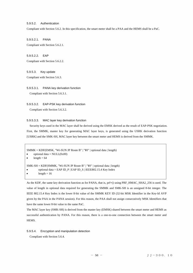
- 56 - JJ-300.10
5.9.5.2. Authentication
Compliant with Section 5.6.2. In this specification, the smart meter shall be a PAA and the HEMS shall be a PaC.
5.9.5.2.1. PANA
Compliant with Section 5.6.2.1.
5.9.5.2.2. EAP
Compliant with Section 5.6.2.2.
5.9.5.3. Key update
Compliant with Section 5.6.3.
5.9.5.3.1. PANA key derivation function
Compliant with Section 5.6.3.1.
5.9.5.3.2. EAP-PSK key derivation function
Compliant with Section 5.6.3.2.
5.9.5.3.3. MAC layer key derivation function
Security keys used in the MAC layer shall be derived using the EMSK derived as the result of EAP-PSK negotiation.
First, the SMMK, master key for generating MAC layer keys, is generated using the USRK derivation function
[USRK] and the SMK-SH, MAC layer key between the smart meter and HEMS is derived from the SMMK.
SMMK = KDF(EMSK, "Wi-SUN JP Route B" | "¥0" | optional data | length)
optional data = NULL(0x00)
length = 64
SMK-SH = KDF(SMMK, "Wi-SUN JP Route B" | "¥0" | optional data | length)
optional data = EAP ID_P | EAP ID_S | IEEE802.15.4 Key Index
length = 16
As the KDF, the same key derivation function as for PANA, that is, prf+() using PRF_HMAC_SHA2_256 is used. The
value of length in optional data required for generating the SMMK and SMK-SH is an unsigned 8-bit integer. The
IEEE 802.15.4 Key Index is the lower 8-bit value of the SMMK KEY ID (32-bit MSK Identifier in the Key-Id AVP
given by the PAA in the PANA session). For this reason, the PAA shall not assign consecutively MSK Identifiers that
have the same lower 8-bit value to the same PaC.
The MAC layer key (SMK-SH) is derived from the master key (EMSK) shared between the smart meter and HEMS as
successful authentication by PANA. For this reason, there is a one-to-one connection between the smart meter and
HEMS.
5.9.5.4. Encryption and manipulation detection
Compliant with Section 5.6.4.

- 57 - JJ-300.10
5.9.5.5. Protection from replay attacks
Compliant with Section 5.6.5.
5.9.6. Recommended network configurations
The smart meter and HEMS use an 8-octet network identifier. This ID is used for association between the smart meter
and HEMS. This specification assumes that this ID is set on the smart meter and HEMS in advance. The specification
also assumes that the NAI and authentication key required for PANA/EAP are set on the smart meter and HEMS in
advance in the same way.
The smart meter shall determine a radio channel to use and PAN ID for constructing a network following the procedure
below.
1-1: Data link layer configurations (smart meter)
The smart meter selects a radio channel and detects a PAN ID using Energy Detection Scan (ED Scan) and Enhanced
Active Scan. Selection criteria of the radio channel and PAN ID is out of scope of this profile.
1-2: Network layer configurations (smart meter)
The smart meter determines its own IPv6 link local address according to the description in [SLAAC]. After the smart
meter has constructed a network in which it acts as the coordinator, the HEMS sets the following data link layer and
network layer configurations to connect itself to the home smart meter.
2-1: Data link layer configurations (HEMS)
The HEMS detects the smart meter to connect using Enhanced Active Scan.
2-2: Network layer configurations (HEMS)
The HEMS determines its own IPv6 link local address according to the description in [SLAAC].
The HEMS calculate the IPv6 link local address of the smart meter from the source MAC address in the enhanced
beacon from the smart meter. And, the HEMS requests network authentication by the PANA based on the NAI and
authentication key, which are shared in advance. The smart meter establishes a PANA session with the HEMS and
determines whether to authenticate the HEMS based on the NAI and authentication key, which are shared in advance.
When authentication succeeds, the smart meter and HEMS exchange unique key information for communication and
use the shared key information for communication as the MAC layer encryption key.
After encrypted communication between the smart meter and HEMS is established, communication between the smart
meter and HEMS using encrypted messages starts. The HEMS conducts service discovery using the ECHONET Lite
protocol and the smart meter notifies the HEMS of meter readings every 30 minutes.
5.9.6.1. Construction of a new network
Once turned on, the smart meter constructs a new network compliant with the profile. This procedure is the same as
that described in Section 5.6.2. The procedure for network construction and joining to this network is shown in Figure
5-18.

- 58 - JJ-300.10
Figure 5-18: Overview of network configuration and joining procedure
5.9.6.1.1. Data link layer configurations
Data link layer configurations for the coordinator are the same as described in Section 5.8.2.1. However, the smart
meter uses Enhanced Active Scan and sets no information in the Information Element field.
To detect a smart meter network, the HEMS uses Enhanced Active Scan and sets MLME IE in the Information Element
field. As a response to the Enhanced Beacon Request command from the HEMS, the smart meter returns an enhanced
beacon in which the same MLME IE is contained in the Information Element field. The association procedure is
omitted. Other data link layer configurations for the HEMS are the same as described in Section 5.8.3.1.
Additional information related to these configurations is shown in Table 5-30.
Table 5-30: MLME IE sub-ID allocation
Sub-ID value Content length Name Description
0x68 Variable Unmanaged
(network identifier)
Sub-ID used by the HEMS to identify the
target meter. Defined for this recommended
communication specification.
5.9.6.1.2. Network layer configurations
The smart meter uses the IPv6 link local address only. Other network layer configurations for the smart meter are the
same as described in Section 5.8.2.2.
In the same way, the HEMS also uses the IPv6 link local address only. Other network layer configurations for the
HEMS are the same as described in Section 5.8.3.2.
The authentication procedure is described in Section 5.9.6.3.

- 59 - JJ-300.10
5.9.6.2. IP address detection
Before the authentication procedure by the PANA, the HEMS calculates the IPv6 address of the smart meter. As a way
for mutual address resolution, the HEMS estimates the IPv6 link local address using the MAC address in the enhanced
beacon from the smart meter.
The MAC address is used to determine the IPv6 address, so neighbor discovery specified in [ND] may not be
conducted.
5.9.6.3. Authentication and key exchange
The HEMS conducts security configurations after data link layer and network layer configurations. In other words, the
HEMS acting as a PaC initiates a PANA session with the smart meter acting as the PAA.
5.9.6.4. Application layer
As described in Section 5.5.6, ECHONET Lite is used as the application layer and the compound data format is
supported. For details, see [SMHEMSIF].
5.9.7. Usage of credentials (supplementary information)
In a Japanese Route-B (smart meter-HEMS) network, Route-B specific credentials (Table 5-35) are defined. From
this point of view, this section describes how to use the credentials in the communication protocol.
Table 5-35: Route-B credentials
Name Description
Route-B
authentication ID
Unique ID used to associate a specific smart meter with the HEMS. 32-digit character
string consisting of ASCII characters 0 to 9 and A to F (32 octets). In this specification, the
ID is converted to an ID used by the PANA (EAP-PSK) (in [NAI] format) and network
identifier according to the rules described below.
Password (for
Route-B
authentication)
Password linked to the Route-B authentication ID (12-digit character string consisting of
ASCII characters 0 to 9, a to z, and A to Z). This password is used to generate a PSK used
by [EAP-PSK] according to the rules described below.
5.9.7.1. Conversion of a Route-B authentication ID to EAP authentication information
NAIs used for EAP identifiers (ID_S and ID_P) are generated based on a 32-digit Route-B authentication ID according
to the following rules.
[NAI generation rules]
Smart meter NAI (EAP ID_S): "SM" + "Route-B authentication ID" (34 octets)
HEMS NAI (EAP ID_P): "HEMS" + "Route-B authentication ID" (36 octets)
Example:
When the Route-B authentication ID is "0023456789ABCDEF0011223344556677"
Smart meter NAI (EAP ID_S): "SM0023456789ABCDEF0011223344556677"
HEMS NAI (EAP ID_P): "HEMS0023456789ABCDEF0011223344556677"

- 60 - JJ-300.10
5.9.7.2. Conversion of a password to a PSK
A PSK used by EAP-PSK is generated according to the following rules.
[PSK generation rules]
A 16-octet PSK is generated based on the password linked to a Route-B authentication ID using the following PSK
generation function (PSK_KDF).
PSK = PSK_KDF(password)
= LSBytes16(SHA-256(Capitalize(password))
(16 lower-order octets of the output created by capitalizing the password character string and hashing it using
SHA-256)
Example:
When the password is "0123456789ab"
PSK = LSBytes16(SHA-256("0123456789AB"))
= 0xf58d060cc71e7667b5b2a09e37f602a2
5.9.7.3. Conversion of a Route-B authentication ID to a network identifier
The HEMS conducts Enhanced Active Scan using the IEs field to detect the home smart meter. The HEMS transmits
an enhanced beacon request with setting MLME IE (Group ID = 0x1) in the Payload IEs field and 8 lower-order octets
(network identifier) of the Route-B authentication ID the HEMS has in IE Contents of Sub-ID = 0x68 (Unmanaged).
When the received network identifier is the same as the network identifier the smart meter has, the smart meter returns
an enhanced beacon as a response. This enhanced beacon is transmitted for unicast and contains the same information
in the enhanced beacon request from the HEMS in the Payload IEs field. Through the data exchange above, the HEMS
and smart meter confirms that they have the same ID, and the HEMS initiates a PANA session with the smart meter.
(Figure 5-19)
Figure 5-19: Smart meter discovery procedure
5.9.8. Specifications for the device/physical layer/MAC layer to implement the recommended specification
See Sections 5.9.2 and 5.9.3.
HEMSSmart meter
Enhanced Beacon Request
(Contains the network identifier in IE.)
Enhanced Beacon
(Contains the network identifier in IE.)
Start of a PANA session
Route-B authentication ID: “00112233445566778899AABBCCDDEEFF”Network identifier: “CCDDEEFF”ID_S : “SM00112233445566778899AABBCCDDEEFF”ID_P : “HEMS00112233445566778899AABBCCDDEEFF”

- 61 - JJ-300.10
6. System B
This chapter describes the ZigBee IP specification supporting 920MHz IPv6 specified in [ZIP]. To obtain official
ZigBee certification, see also [ZIP]. ZigBee IP may be referred to as ZIP in this chapter.
For system B, the following three node types shall be specified: ZIP coordinator, ZIP router, and ZIP host. A ZIP
coordinator plays a role in managing a network. A ZIP router has a forwarding function in a multihop network. A star
single-hop network can be constructed with a ZIP coordinator and ZIP host. A multihop network can be constructed
with a ZIP router in addition to them. The protocols to implement for these three types of nodes are specified in [ZIP].
The user can use these protocols in combination according to the purpose. This system does not need to customize the
protocol stack according to the network configuration for each vendor, which provides high interoperability.
Due to good 920MHz radio propagation, in a small home, a single-hop network may be able to be constructed.
However, cases where radio waves are not reached via a single-hop network are reported, depending on the device
installation location and design condition, for example, when a built-in small antenna is used, a device is installed
behind or in a home electrical appliance or another metallic product, or a device is installed in an outdoor facility. In
these cases, system B that can support a multihop network is effective.
For system B, a function for improving the security and link stability has already been specified, and system B is
only one among the three systems that uses a global address, which provides high connectivity with other home IP
systems and external IP networks.
In addition, for the network layer in system B, not only the IETF standards are referenced, but also specifications are
added to ensure interoperability. Implementation according to this chapter will improve interoperability. By obtain
certification from ZigBee Alliance, interoperability with other systems is guaranteed.
6.1. Overview
6.1.1. Purpose
The purpose of the ZigBee IP specification is to define a standard, interoperable protocol stack using IETF-defined
networking protocols for use in IEEE 802.15.4-based wireless multihop networks.
6.1.2. Scope
This chapter contains the specification for the ZigBee IP protocol stack for use in ECHONET Lite.
This standard uses IETF and IEEE specifications. This chapter describes changes to these specifications (including
the use of a mandatory function as an optional function and the use of an optional function as a mandatory function).

- 62 - JJ-300.10
6.1.3. Overview of the protocol stack
The ZigBee IP protocol stack is illustrated in the figure below.
Figure 6-1: ZigBee IP protocol stack
The data link layer provides the following services:
・ Discovery of an IEEE 802.15.4 PAN in radio propagation range
・ Transmissions with the maximum MAC payload size (specified separately). The actual MAC payload in each
frame differs depending on the mode, security options, and addressing.
・ Support for frame transmissions to sleeping devices using frame buffering and polling
・ Frame security including encryption, authentication, and replay protection. Note that key management is not
performed in this layer.
The 6LoWPAN adaptation layer provides the following services:
・ IPv6 and UDP header compression and decompression
・ Fragmentation and reassembly of an IPv6 packet that exceeds the maximum payload size available in the data
link layer frame
The network layer provides the following services:
・ IPv6 address management and packet framing
・ ICMPv6 messaging
・ Router and neighbor discovery
・ IPv6 stateless address autoconfiguration and duplicate address detection (DAD)
・ Propagation of 6LoWPAN configuration information
・ Route computation and maintenance using the RPL protocol
・ IPv6 packet forwarding
Link layer(IEEE802.15.4-2006、
IEEE802.15.4g-2012)
Applications(ECHONET Lite)

- 63 - JJ-300.10
・ IPv6 multicast forwarding within the subnet
The transport layer provides the following services:
・ Guaranteed and non-guaranteed packet delivery service
・ Multiplexing of packets to multiple applications
The management entity is a conceptual function that is responsible for invoking and managing various protocols to
achieve the desired operational behavior by the node. It is responsible for:
・ Node bootstrapping process
・ Node power management
・ Non-volatile storage and restoration of critical network parameters
・ Authentication and network access control using PANA protocol
・ Network-wide key distribution using PANA protocol
・ Propagation of network configuration parameters using MLE protocol
6.1.4. Document organization
The rest of the document is organized as follows. Section 6.2 contains the ZigBee IP protocol specification. It
describes the various IEEE and IETF standard protocols that must be supported by a ZigBee IP implementation along
with details on the mandatory and optional functions within each of them. Section 6.3 describes the functional behavior
of a ZigBee IP node during various stages of network operation. Section 6.4 contains informative material and
examples of protocol message exchanges that may be useful for implementation of this specification.
Change conditions for 920MHz support are found in Section 6.6. The implementation specifications for the physical
and data link layers are given in Section 6.7.
Some external documents are referenced as a document specified in this chapter, for example, [802.15.4] listed in
Chapter 3 Reference Standards and Documents and others are directly referenced with its well-known document
number specified by an organization such as IETF, for example, [RFC 4944].
6.2. Protocol specification
6.2.1. Physical layer
A ZigBee IP node must support at least one physical interface conforming to one of the physical specifications
defined in IEEE 802.15.4-2006, [802.15.4], and IEEE 802.15.4g-2012.
This standard supports only a single physical interface and does not support multiple physical interfaces.
6.2.2. Data link layer
A ZigBee IP node must implement the data link layer specification in IEEE 802.15.4-2006 [802.15.4]. A ZIP host
must implement at least the RFD (reduced function device) function. On the other hand, a ZIP router and ZIP
coordinator must implement the FFD (full function device) function.
A ZIP node is not required to implement all available data link functions. Specifically, the beacon mode and
guaranteed timeslots (GTS) functions are not required for ZigBee IP networks. The Association and Disassociation
command frames are not required to be supported.
A ZIP node must support the data link layer security functions described in Section 6.4 in this document.
A ZigBee IP node must support the 64-bit and 16-bit data link layer addressing modes. An EUI-64 address must be

- 64 - JJ-300.10
configured in each device at manufacture time. This address is globally unique and it is expected that this address is
fixed during the lifetime of the device. A 16-bit short address must be assigned to each device after it has completed
network admission. This address is unique within that particular IEEE 802.15.4 PAN.
6.2.3. Adaptation layer
The adaptation layer using 6LoWPAN is defined by standards produced by the 6LoWPAN Working Group of the
IETF.
The encapsulation of IPv6 packets in IEEE 802.15.4 frames must be performed as specified in [6LOWPAN] and
[6LPHC]. The mesh addressing header is not required to be supported as ZigBee IP does not use the link-layer
mesh-under routing configuration described in [6LOWPAN] and instead relies on the route over configuration.
6.2.3.1. 6LoWPAN fragmentation
The 6LoWPAN fragmentation scheme defined in [6LOWPAN] must be supported.
The fragments composing a single IP datagram must be transmitted in order of increasing datagram_offset. In
addition, the transmission of fragments of one datagram must not be interleaved with any other datagrams fragmented
or otherwise, to the same destination. (While [6LOWPAN] allows fragments and packets to be transmitted in any order,
having fragments arrive in order and not interleaved during reassembly simplifies both data reassembly and detection
of missing fragments. The physical and data link layers used for ZigBee IP do not themselves reorder packets, so the
above restrictions are sufficient to ensure in-order packet arrival.)
The link MTU for the 6LoWPAN interface must be set 1280 octets (see Section 6.2.4.3 for exceptions).
6.2.3.2. Header compression
The 6LoWPAN header compression scheme defined in header compression [6LPHC] must be supported by a
ZigBee IP node. A ZigBee IP node must support all compression modes defined in [6LPHC]. When an IPv6 packet is
transmitted, the most effective compression scheme should be used to minimize the size of the transmitted packet. A
node should be able to receive an IPv6 packet with any or no header compression as long as the header is encoded
using the format defined in [6LPHC].
[6LPHC] specifies the use of pre-defined context identifiers for the purpose of compressing IPv6 addresses. These
context identifiers are defined at the 6LBR and conveyed to the other nodes in the network via router advertisements
[6LPND].
The 6LBR in a ZigBee IP network must not define more than MIN_6LP_CID_COUNT context identifiers for
purposes of IP header compression. It must define the default context identifier (context zero) and set its value to the
IPv6 prefix assigned to the 6LoWPAN, as defined in Section 6.1.
All other ZIP nodes must support the configuration and use of at least MIN_6LP_CID_COUNT context identifiers
for purposes of IPv6 header compression.
6.2.3.3. Neighbor discovery
The neighbor discovery protocol must be implemented as defined in 6LoWPAN neighbor discovery specification
[6LPND].
A ZigBee IP node must support the optional mechanisms defined in [6LPND] for multihop distribution of prefix and
context information.
A ZigBee IP node must support the optional mechanisms defined in [6LPND] for multihop duplicate address

- 65 - JJ-300.10
detection.
A ZigBee IP node should suppress neighbor unreachability probes as the upper layer protocols specified in later
sections include periodic packet transmissions that detect the bidirectional reachability of neighbor nodes as well as
detecting new neighbor nodes. However, all nodes must respond appropriately to a neighbor unreachability probe.
6.2.4. Network layer
A ZigBee IP node must support the IPv6 protocol [IPv6].
A ZigBee IP node is not required to support Authentication Header (AH) and Encapsulating Security Payload (ESP)
IPv6 extension headers and this mode of operation is not described in this standard.
A ZigBee IP node is not required to support the Fragment IPv6 extension header.
A ZigBee IP node must support the ICMPv6 protocol [ICMP6]. Nodes must support the ICMPv6 error messages as
well as the echo request and echo reply messages.
6.2.4.1. IP addressing
All ZigBee IP nodes must support the IPv6 addressing architecture specified in [IP6ADDR].
A ZigBee IP network will be assigned one or more /64-bit prefix(es), which will be announced as the prefix(es)
throughout the entire 6LoWPAN (see [6LPND]). These prefix(es) may be either ULA [ULA] or GUA prefix(es). A
node must be capable of supporting at least MIN_6LP_PREFIX prefixes. For consistency with [ND], [6LOWPAN],
and other standards, the 6LoWPAN prefix(es) must always be /64 bits long. A 6LoWPAN node can use either its
EUI-64 address or its 16-bit short address to obtain the interface identifier, as defined in Section 6 of [6LOWPAN].
When the 16-bit short address is used to construct the interface identifier, the method specified in [6LPHC] must be
followed. When applied to header compression modes that are based on the 16-bit short address, the /64-bit prefix from
the default context and the additional 48 bits that convert the 16-bit short address to a 64-bit IID are elided from the
compressed address.
A ZigBee IP node must configure its IEEE 802.15.4 interface with at least the following addresses:
A 128-bit link-local IPv6 address configured from the EUI-64 of the node as the interface identifier using the
well-known link-local prefix FE80::0/64 as described in [SLAAC] and [6LOWPAN]. When this type of
address is compressed using [6LPHC], it must be considered stateless compression. This type of address is
known in its abbreviated form as LL64.
A 128-bit link-local IPv6 address configured from the interface identifier based on the 16-bit short address of
the node using the well-known link-local prefix FE80::0/64 as described in [SLAAC] and [6LOWPAN].
When this type of address is compressed using [6LPHC], it must be considered stateless compression. This
type of address is known in its abbreviated form as LL16.
One or more 128-bit unicast IPv6 address(es). The interface identifier used for address configuration is based
on the 16-bit short address of the node. The prefix is the ULA or GUA prefix obtained from the 6LoWPAN
Prefix information option (PIO) in the router advertisement ([6LPND]). If multiple global prefixes are
advertised, the node may choose to configure addresses with any or all of them based on local node policy.
When this type of address is compressed using [6LPHC], it must be considered stateful, context based
compression. This type of address is known in its abbreviated form as GP16.
In addition, all nodes must join the appropriate multicast addresses as required by [ND].

- 66 - JJ-300.10
DAD must not be performed on addresses configured from an EUI-64 interface identifier, as recommended in
[6LPND]. The GP16 address configured from the 16-bit short address must be tested for uniqueness using the DAD
mechanism [6LPND].
6.2.4.2. Routing protocol
All ZigBee IP routers must implement the RPL routing protocol [RPL]. RPL establishes a destination oriented
directed acyclic graph (DODAG) toward a root node, called the DODAG root. Packets are directed up the DODAG
toward the root using this graph. Packets are directed from the root down the DODAG using routes established from
Destination Advertisement Object (DAO). The following subsections describe how RPL is used in ZigBee IP to ensure
compatibility between devices.
A ZigBee IP network may run multiple RPL instances concurrently. Only global instances should be used. The LBR
node must start an RPL instance. Other ZigBee IP routers may start their own RPL instance if they offer connectivity
to an external network or if they are administratively configured to do so. In this case, the RPL instance identifier
should be selected so that it does not conflict existing identifiers. This means that the router should first join the
network and discover existing RPL instances before starting its own RPL instance. The presence of DIOs with different
DODAG id fields but equal instance id fields indicates a duplicate instance id. If a DODAG root detects an instance id
conflict with its instance, it should reform the DODAG using a different instance id.
A ZigBee IP router must be capable of joining at least MIN_RPL_INSTANCE_COUNT RPL instances and should
join all RPL instances that are available in the network subject to its memory constraints.
If a node loses connectivity to an RPL instance (that is, it cannot find a parent with finite rank) for over
RPL_INSTANCE_LOST_TIMEOUT seconds, it should delete the instance. This may happen, for example, if the root
of the instance is replaced.
Each DODAG root may be configured to include zero or more prefixes in the Route Information Option (RIO). Note
that if the root wishes to advertise the default route (prefix 0::), it must include it in an RIO. The absence of any RIO
prefixes indicates that the DODAG can route packets only to the root node. If the DODAG root is also the
Authoritative Border Router [6LPND], it must include the PIO information in both the RPL DIO packet as well as the
Router Advertisement packet.
In a ZigBee IP network, an RPL instance must contain a single DODAG with a single root. A DODAG root must
always be grounded. Floating DODAG must not be used.
RPL control messages are transmitted using "unsecured" RPL security mode. Link layer security is used to meet the
security requirements.
In a ZigBee IP network, only the non-storing RPL mode of operation is used. In the non-storing mode, all downward
routes are managed by the DODAG root as source routes. Routers transmit DAO messages containing downward route
information directly to the root, with the DAO-ACK ('K') flag enabled. DAO messages are not delayed at each hop (see
[RPL] section 9.5). DAO messages should be jittered by the originating router to avoid multiple nodes transmitting
simultaneously to the root. Multicast DAO messages are not used in a ZigBee IP network.
Every non-root router should be capable of having at least RPL_MIN_DAO_PARENT parents per DODAG, to be
used for upward routing by the router itself, and downward routing by the root.
Metric Container and RPL Target Descriptor options must not be included in any RPL control messages.
6.2.4.2.1. Host participation in RPL
A ZIP host does not participate in the RPL protocol.

- 67 - JJ-300.10
6.2.4.2.2. Objective function
The objective function defines the route selection objectives within an RPL instance. The objective function is
identified by the objective code point (OCP) field in the DODAG configuration option.
A ZigBee IP router must implement the MRHOF objective function [RPL-MRHOF] using the ETX metric, without
metric containers.
ZigBee IP routers must use the Mesh Link Establishment protocol [MLE] to determine the ETX of links to neighbor
routers. Routers estimate the incoming delivery ratio for each neighbor node in their neighbor table. The estimation
method depends on the implementation. The inverse of the incoming delivery ratio is then communicated to the
neighbor via the MLE Neighbor TLV. The ETX of the link is equal to the product of the forward and reverse inverse
incoming delivery ratios.
MRHOF parameters must be set as follows:
MAX_LINK_METRIC: 16 * MinHopRankIncrease.
MAX_PATH_COST: 256 * MinHopRankIncrease.
MIN_PATH_COST: 0.
PARENT_SWITCH_THRESHOLD: 1.5 * MinHopRankIncrease.
PARENT_SET_SIZE: 2.
ALLOW_FLOATING_ROOT: 0.
6.2.4.2.3. RPL configuration
This section specifies the RPL configurations and RPL control messages used by ZigBee IP. Any unspecified
configurations are used as defined in [RPL].
The DODAG root is authoritative for setting some information through DIO and the information is unchanged
during propagation toward leaf nodes. This information is described below:
1. RIO(s) (if any)
2. DODAG configuration option
3. PIO(s) (if any), with the exception that if the 'R' flag is set, the last two octets of the IPv6 address (link layer
short address) in the Prefix field will change.
4. RPLInstanceID
5. DODAGID
6. DODAGVersionNumber
7. Grounded flag
8. Mode of operation field
6.2.4.2.3.1. DODAG Information Solicitation (DIS) frame format
The DIS messages may include the Pad1, PadN, or Solicited Information options.
A ZIP router may transmit a DIS message with the Solicited Information option and the InstanceID predicate in

- 68 - JJ-300.10
order to limit the DIO response to a specific RPL instance.
6.2.4.2.3.2. Multicast DODAG Information Object (DIO) frame format
A multicast DIO message contains the DIO base object and the RIO objects.
The configuration of the DIO base is as follows:
The RPLInstanceID should be set to a global instance with a value in the range of [0x00, 0x7F].
The Version Number should be initialized to a value of 0xF0.
Grounded (G): The Grounded flag of the DIO must always be set. ZIP nodes must not create floating
DODAGs.
Mode of Operation (MOP): The Mode of Operation (MOP) field in the DIO must be set to 0x01. This indicates
the non-storing mode in RPL.
DODAGPreference: The DODAGPreference field should be set to 0. ZIP routers are not required to
implement DODAG preference based on this field.
Destination Advertisement Trigger Sequence Number (DTSN) - The root node increments the DTSN field of
the DIO when it wishes to receive fresh DAO messages from the network without incrementing the DODAG
version number. ZIP routers must set their DTSN counter to the same value as their parent router and update
it whenever the parent router updates its value. This way the root node can increment the value in its DTSN
field and propagate that change through the entire DODAG.
The configuration of the RIO is as follows:
The Prefix Length should be set to the length of the prefix for which the route is being advertised.
The Route Preference (Prf) value should be set to 0 (medium) preference or administratively configured.
The prefix should be set to the value for which the route is being advertised.
RPL allows the root to include multiple RIO options in a DIO frame to advertise external routes that are reachable
through the root. A ZIP node operating as an RPL root should limit the number of RIO options included in the DIO
packet to RPL_MAX_RIO. This is to ensure that all ZIP routers can process the necessary route information. Similarly,
an RPL root should limit the number of PIO options included in the DIO packet to RPL_MAX_PIO.
6.2.4.2.3.3. Unicast DODAG Information Object (DIO) frame format
A unicast DIO message contains the DIO base, RIO(s), PIO(s), and DODAG configuration option. The DIO base
and RIO used in unicast messages have the same format as in multicast messages.
The configuration of the PIO is as follows:
The Prefix Length must be set to 0x40, indicating a 64-bit prefix.
The 'L' flag (on-link flag) must not be set (see [6LPND] 6.1).

- 69 - JJ-300.10
The 'A' flag (autonomous address-configuration flag) must be set if the prefix can be for stateless address
autoconfiguration.
The 'R' flag (router address flag) must be set if the node has configured an address with this prefix. Otherwise,
it must not be set.
The Prefix field must contain the routable IPv6 address of the source node.
The configuration of the DODAG configuration option is as follows:
The Authentication Enabled (A) flag must not be set. ZigBee IP does not use RPL security and instead relies on
data link layer security.
The Path Control Size (PCS) field must be set to 2. This controls the number of DAO parents and that of
downward routes that are configured for a ZIP node.
The trickle parameters that govern the DIO transmission should be set by the RPL root. The parameters should
be set to balance the amount of traffic generated by the trickle timer reset against the joining startup time.
The following parameter values are recommended:
o The DIOIntervalDoublings value should be set to 12.
o The DIOIntervalMin value should be set to 9.
o The DIORedundancyConstant value should be set to 3.
The ZIP routers must configure their internal DIO trickle timer parameters based on the incoming
DODAG configuration option and must not hardcode the above recommended values.
The MaxRankIncrease field should be set to a value other than 0. MaxRankIncrease is used to configure the
allowable rank increase in support to local repair. If it is set to 0, local repair is disabled. A typical value for
this field would be about 16 and a larger value should be in networks with more hops.
The MinHopRankIncrease field should be set to 0x80.
The Object Code Point (OCP) must be set to the assigned value in [RPL-MRHOF].
6.2.4.2.3.4. Destination Advertisement Object (DAO) frame format
A unicast DAO request is transmitted to the DODAG root node in order to establish the downward routes. This
request is composed of the DAO base, RPL target option(s), and Transit Information option(s).
The configuration of the DAO base is as follows:
RPLInstanceID: Must be a global RPLInstanceID which must be in the range [0x00, 0x7F].
'K' flag: Should be set. This flag indicates that the DODAG root is expected to transmit a DAO-ACK back.
'D' flag: Must be cleared as local RPLInstanceIDs are not used.

- 70 - JJ-300.10
The DAOSequence should be initially set to 0xF0 and incremented in a "lollipop" fashion afterwards. A node
should increment the DAO sequence number when it retransmits a DAO due to lack of DAO-ACK.
At least one RPL target option must be present in the DAO request. The RPL target option is used to inform the
DODAG root that a route to the target IPv6 address exists.
The configuration of the RPL target option is as follows:
The Prefix Length should be set to "0x80" since an IPv6 address is present in the target prefix.
The target prefix should be set either to the IPv6 address of the ZIP router that is transmitting the DAO packet
to the DAO router or to the IPv6 address of a ZIP host that is directly reachable by that router.
The Transit Information option is used to indicate the DODAG parents to the DODAG root. The configuration of the
Transit Information option is as follows:
The External (E) flag must be set to 0 when the target prefix contains the IPv6 address of the ZIP router that is
transmitting the DAO packet. Otherwise, it must be set to 1.
The Path Control field is used for limiting the number of DODAG parents included in a DAO request and for
setting a preference among them.
The Path Sequence should be updated for each new DAO packet.
The Path Lifetime must be set to the lifetime for which the DAO parent is valid. It must be set to zero when the
ZIP router wants to delete an existing DAO parent from its downward routing table entry at the DODAG
root.
A single parent address must be present in the Transit Information option and it must contain the IPv6 address
of the DODAG parent or the IPv6 address of the node generating the request when a DAO is transmitted on
behalf of the host. Multiple parent addresses may be conveyed using multiple Transit options.
The RPL root determines the freshness of the routing information received through a DAO packet before updating
its source route entries. When the DAO carries route information for host nodes, indicated by the setting of the 'E' flag,
the root must use time-of-delivery as the freshness indicator. That is, a DAO that arrives latter in time is assumed to
contain more recent route information. Otherwise, the root is free to determine the freshness using a combination of
time-to-delivery, DAO sequence, and path sequence values.
6.2.4.2.3.5. Destination Advertisement Object ACK (DAO-ACK) frame format
The DAO-ACK request is transmitted from the DODAG root to the node generating the DAO request. The root
must acknowledge each received DAO packet irrespective of its sequence number.
The configuration of the DAO-ACK is as follows:
The RPLInstanceID field must be set to the instance.
The 'D' flag should be set to zero as local RPL instances are not used.
The TDODAGID field is not present when the "D" flag is zero.

- 71 - JJ-300.10
6.2.4.3. IP traffic forwarding
A ZIP router may forward unicast packets directly to the destination if the destination node is known to be directly
reachable. Otherwise, it should forward unicast packets using the forwarding rules defined in the RPL protocol.
The RPL protocol requires that all data packets forwarded in the RPL domain must contain either the RPL Option
[RPL-OPT] or RPL Source Route [RPL-HDR] header.
The Source Routing header may only be inserted by the DODAG root of the RPL instance. The Source Routing is
used for ① P2MP (point to multipoint) traffic originating outside the DODAG and delivered through the DODAG
root and for ② P2P (point to point) traffic, which is forwarded from the source up the DODAG to the root and then
forwarded back down the DODAG to the destination. The DODAG root will use the node specific routing information
developed through information contained in the RPL DAO packets to forward IPv6 traffic to nodes in the DODAG.
When the DODAG root initiates transmission or receives an IPv6 datagram with the destination address of one of the
nodes in the DODAG, the root will add source routing information to the IPv6 datagram according to [RPL-HDR].
The DODAG root should insert the Source Routing header directly only in the case where it is the source of the IPv6
packet and the destination is within the RPL domain (that is, it is a ZIP router with the same prefix). In all other cases,
it must use "IPv6-in-IPv6 tunneling". The tunnel exit point must be set to the address of the final destination address if
that node is within the RPL domain. Otherwise, it must be set to the parent address of the destination. The DODAG
root determines the parent address from the Transit Information option in the DAO packet that has a Target option
corresponding to the destination address.
A ZIP router that is originating a unicast IPv6 packet and forwarding it via the RPL protocol must insert the RPL
Option header. The header must be inserted using tunneling in all IPv6 based cases except when the destination address
is the DODAG root of the RPL instance used by the packet. In that case, the header may be inserted either directly in
the packet or by using "IPv6-in-IPv6" tunneling. When the RPL Option header is inserted using tunneling, the tunnel
exit point should be set to the next hop address along the route towards the DODAG root. In the case where the final
destination address of the packet is the DODAG root of the RPL instance used by the packet, the tunnel exit point may
be set to that address.
A ZIP router that is using RPL to forward a unicast IPv6 packet originated by another node must insert the RPL
Option header if the packet does not already contain either the RPL Option header or Source Routing header. The
header must be inserted using "IPv6-in-IPv6" tunneling. The tunnel exit point should be set to the next hop address
along the route towards the DODAG root. In the case where the final destination address of the packet is the DODAG
root of the RPL instance used by the packet, the tunnel exit point may be set to that address.
A ZIP node must ensure that the insertion of an RPL extension header, either directly or via IPv6-in-IPv6 tunneling,
does not cause IPv6 fragmentation. This is done by using a different MTU value for packets in which the IPv6 header
includes an RPL extension header. The RPL tunnel entry point should be considered as a separate interface whose
MTU is set to the 6LoWPAN interface MTU plus RPL_MTU_EXTENSION octets.
A ZIP host node should forward packets to its default parent router (this is the router through which the host has
registered its address, as described in [6LPND]). If the parent router determines that the packet needs to be forwarded
using the RPL forwarding rules, it inserts the necessary RPL extension header following the rules described above.
6.2.4.4. Multicast forwarding
The multicast scope value of 3 [IP6ADDR] is defined as a "subnet-local" scope that comprises of all links within a
single network and all interfaces of ZIP nodes. Thus, a ZIP network forms a subnet-local multicast zone [RFC 4007]
with a scope value of 3.

- 72 - JJ-300.10
All ZIP nodes must be connected to the subnet-scope-all-nodes multicast group (FF03:0:0:0:0:0:0:1) (consisting of
all nodes on the subnet and subnet-scope-all-mpl-forwarders (all MPL forwarding nodes on the subnet) on their ZIP
interface. All ZIP routers must be connected to the subnet-scope-all-routers multicast group (FF03:0:0:0:0:0:0:2)
(consisting of all routers on the subnet) on their ZIP interface. ZIP nodes may be connected to additional subnet-scope
multicast groups based on administrative configuration.
ZIP nodes use the MPL protocol [MPL] for multicast IP packet dissemination. All ZIP nodes must configure the ZIP
interface as an MPL interface. All ZIP nodes may originate and receive MPL data messages and ZIP routers may also
forward MPL data messages to other nodes.
The MPL protocol requires each forwarding node to participate in at least one MPL domain specified by the
subnet-scope-all-mpl-forwarders group. In addition, ZIP nodes must participate in the MPL domains specified by each
of the subnet-scope multicast addresses that are subscribed on the ZIP interface.
ZIP nodes must configure the MPL parameters as follows:
The PROACTIVE_PROPAGATION flag must be set to true. This indicates that MPL forwarding is performed
proactively.
DATA_MESSAGE_IMIN = 512ms
DATA_MESSAGE_IMAX = 512ms
DATA_MESSAGE_K = infinite
DATA_MESSAGE_TIMER_EXPIRATIONS = 0 for ZIP hosts and 3 otherwise
CONTROL_MESSAGE_TIMER_EXPIRATIONS = 0
Note that setting the DATA_MESSAGE_TIMER_EXPIRATION parameter to 0 on ZIP hosts results in disabling
forwarding and retransmission of MPL data messages. Similarly, setting the CONTROL_MESSAGE_TIMER_
EXPIRATION parameter to 0 on all ZIP nodes means that MPL control messages are not transmitted in a ZIP network.
MPL data messages contain the MPL Option in an IPv6 Hop-by-Hop header. ZIP nodes must configure the MPL
Option as follows:
The value of the S field must be set to 1 to indicate that the seed-id is a 16-bit value.
The value of the seed-id field must be set to the MAC short address of the node originating the MPL data
message.
6.2.5. Transport layer
6.2.5.1. Connection oriented service
All ZigBee IP nodes must support the TCP (Transmission control protocol) protocol as defined in [TCP].
6.2.5.2. Connectionless service
All ZigBee IP nodes must support the UDP (User Datagram Protocol) protocol as defined in [UDP].
6.2.6. PANA
The Protocol for Carrying Authentication for Network Access [PANA] must be used as the EAP transport for
carrying authentication data between a joining node and the Network Authentication Server. This section clarifies the

- 73 - JJ-300.10
definitions of constraints and specifications above and beyond those specified in [PANA] and [PANA-ENC].
6.2.6.1. PRF (pseudo random function), message authentication, and encryption algorithms
Only the following algorithm identifiers must be used:
Table 6-1: PANA algorithm identifiers
Algorithm Type Value Comment
PRF PRF_HMAC_SHA2_256 5 IKEv2 Transport Type 2
AUTH AUTH_HMAC_SHA2_256 12 IKEv2 Transport Type 3
Encryption AES-CTR 1
The proposed PRF and AUTH hash algorithms based on SHA-256 are described in [IKEv2] and detailed in
[IPSEC-HMAC]. The proposed Encryption algorithm is used by [PANA-ENC].
6.2.6.2. Network security material
The PANA protocol is used to transport the network security material from the Authentication Server to each
authenticated node in the ZigBee IP network. This security material is used by each node to further derive encryption
keys that are used to provide security for other protocols. The network security material consists of the following
parameters.
Table 6-2: Network security material
Parameter Size Comment
Network Key 16 octets
Common network-wide security key that is forwarded using
PANA by the Authentication Server to all authenticated ZIP
nodes in the network
Key sequence number 1 octet Sequence number associated with this network key
Node Auth Counter 1 octet Value of the authentication counter to be used by each node.
This parameter is unique for each node in the network.
The Network Key is owned and managed by the Network Authentication Server. Each Network Key has a sequence
number which takes a value between 1 and 255. The Network Authentication Server manages updates of the Network
key and associated sequence number and defines which Network Key is active.
In addition, the Authentication Server manages an Auth Counter parameter for each node in the network. The
combination of the Network Key, Key sequence number, and Auth Counter is transported as a single entity by the
Authentication Server to each node.
6.2.6.3. Vendor-specific AVPs
The following ZigBee Alliance vendor-specific "PANA AVPs" are defined to support the transport and update of the
network security material. As these are vendor-specific AVPs, as long as they are defined in this document, they shall
not be defined or referenced in any other documents.
The private enterprise number (PEN) assigned to the ZigBee Alliance through the IANA is 37244. The assignment is
given in the following website: http://www.iana.org/assignments/enterprise-numbers

- 74 - JJ-300.10
6.2.6.3.1. Network key AVP
The purpose of this AVP is to securely forward the network security parameters from the Authentication Server to
each node.
struct PANAAVP {
uint16 code = 1; /* ZigBee Network Key */
uint16 flags = 1; /* Vendor-specific */
uint16 length = 18;
uint16 rsvd = 0;
uint32 vendor_id = 37244; /* ZigBee Alliance PEN */
struct ZBNWKKEY {
uint8 nwk_key[16]; /* NwkKey */
uint8 nwk_key_idx; /* NwkKeyIdx */
uint8 auth_cntr; /* AuthCntr */
};
struct AVPPad {
uint8 bytes[2];
};
};
6.2.6.3.2. Key request AVP
The purpose of this AVP is to allow a PaC to request the PAA to transport either a new network key or an update
auth counter for the current network key.
struct PANAAVP {
uint16 code = 2; /* ZigBee Key Request */
uint16 flags = 1; /* Vendor-specific */
uint16 length = 2;
uint16 rsvd = 0;
uint32 vendor_id = 37244; /* ZigBee Alliance PEN */
struct ZBNWKKEYREQ {
uint8 nwk_key_req_flags; /* request flags */
uint8 nwk_key_idx; /* NwkKeyIdx */
};
struct AVPPad {
uint8 bytes[2];
};
};
6.2.6.4. Timeouts
Retransmission timeout timers are specified in Chapter 9 in [PANA]. The following values should be used.

- 75 - JJ-300.10
Table 6-3: PANA timeout values
Parameter Value Comment
PCI_IRT 1 sec Initial PCI timeout
PCI_MRT 120 secs Maximum PCI timeout value
PCI_MRC 5 Maximum number of PCI retransmission attempts
PCI_MRD 0 Maximum PCI retransmission duration
REQ_IRT 15 sec Initial Request timeout
REQ_MRT 30 secs Maximum Request timeout value
REQ_MRC 5 Maximum number of Request retransmission attempts
REQ_MRD 0 Maximum Request retransmission duration
6.2.7. EAP
The Extensible Authentication Protocol (EAP) is an authentication framework which supports multiple
authentication methods (known as EAP methods). This section clarifies the definitions of constraints and specifications
above and beyond those specified in [EAP].
The ZIP coordinator must function as an EAP authenticator while all other nodes must function as an EAP peer.
6.2.7.1. EAP Identity
The EAP Request/Identity message is optional. However, the EAP Response/Identity must be supported by the
client in response to the Request/Identity. The EAP identity (given in a response message to an EAP Request/Identity)
must be "anonymous" to prevent any information about the EAP client/peer from being revealed in clear text during
the initial transactions of the authentication. The string must not be null-terminated, that is, shall have a length of 9
octets.
6.2.8. EAP-TLS
EAP-TLS represents a specific type of EAP method (see [EAP]). This section clarifies the definitions of constraints
and specifications above and beyond those specified in [EAP-TLS].
6.2.8.1. EAP key expansion from the master secret
[EAP-TLS] specifies the key expansion for derivation of keying and IV (Initial Vector) material. This section
defines the specific expansion for the cipher suits used and the use of the outputs.
MSK = PRF(master_secret, "client EAP encryption", ClientHello.random +
ServerHello.random);
The string "client EAP encryption" must not be null-terminated, that is, shall be a length of 21 octets.
The PRF function must be iterated twice as the MSK length is 64 octets and the hash output from SHA-256 is only
32 octets. The EMSK must not be used and therefore does not need to be generated.
The MSK must be used as defined in [PANA] and [PANA-ENC] to generate PANA_AUTH_KEY and
PANA_ENCR_KEY.

- 76 - JJ-300.10
6.2.8.2. EAP-TLS fragmentation
It is mandatory for EAP-TLS peers and servers to support fragmentation as described in [EAP-TLS] Section 2.1.5.
EAP peers and servers must support EAP-TLS fragmentation. When performing EAP-TLS fragmentation, ZIP nodes
must ensure that the maximum size of TLS data in a single EAP packet does not exceed EAP_TLS_MTU octets.
However, ZIP nodes must still be capable of receiving EAP packets up to the maximum MTU size as they may
originate from outside the ZigBee IP network.
6.2.9. TLS
Transport Layer Security version 1.2 (TLS) is used in conjunction with PANA, EAP, and EAP-TLS to provide
authentication between a joining node and the Authentication Server. This section clarifies the definitions of
constraints and specifications above and beyond those specified in [TLS].
6.2.9.1. TLS cipher suites
6.2.9.1.1. TLS-PSK cipher suite
As defined in [TLS-CCM], the PSK cipher suite must be TLS_PSK_WITH_AES_128_CCM_8.
6.2.9.1.1.1. Generation of the master secret from the PSK pre-master secret
[TLS-PSK] specifies the generation of the master secret from the pre-master secret. This section specifies the
specific generation for the PSK cipher suite used.
master_secret = PRF(pre_master_secret, "master secret", ClientHello.random +
ServerHello.random);
The string "master secret" must not be null-terminated, that is, it shall be a length of 13 octets.
The PRF function must be iterated twice as the master_secret length is 48 octets and the hash output from
SHA-256 is only 32 octets.
6.2.9.1.2. TLS-ECC cipher suite
As defined in [TLS-ECC-CCM], the ECC cipher suite must be TLS_ECDHE_ECDSA_WITH_AES_128_CCM_8.
As defined in [ECDP], the only elliptic curve to be used with this cipher suite must be the secp256r1 curve (also
known as the NIST-P256 curve).
The hash algorithm to be used with this cipher suite must be SHA-256.
6.2.9.2. TLS key expansion from the master secret
[TLS] specifies the key expansion for generation of keying and IV material. This section defines the specific
expansion for the cipher suites used and the use of the outputs.
key_block = PRF(master_secret, "key expansion", ServerHello.random +
ClientHello.random);
The string "key expansion" must not be null-terminated, that is, it shall be a length of 13 octets.
The PRF function must be iterated twice as the key_block length is 40 octets and the hash output from SHA-256 is
only 32 octets.

- 77 - JJ-300.10
The client_write_MAC_key and server_write_MAC_key lengths are 0 due to the use of AEAD
cipher.
The client_write_key and server_write_key lengths are 16 octets. (SecurityParameters
enc_key_length for [TLS-CCM] and [TLS-ECC-CCM])
The client_write_IV and server_write_IV lengths are 4 octets. (SecurityParameters
fixed_iv_length for [TLS-CCM] and [TLS-ECC-CCM])
A total of 40 octets shall be required for keying material as follows:
o client_write_key must be key_block[0:15].
o server_write_key must be key_block[16:31].
o client_write_IV must be key_block[32:35].
o server_write_IV must be key_block[36:39].
6.2.9.2.1. CCM inputs
Only one CCM-protected record in the TLS sequence is used. This section defines the inputs for the AEAD cipher
defined in [AEAD] Section 2.1.
6.2.9.2.1.1. CCM key input
The key used in the TLS sequence is client_write_key or server_write_key, depending on whether the client
or server is encrypting.
6.2.9.2.1.2. CCM nonce input
The nonce is 12 octets long, as specified in [AEAD], and must be as follows.
Table 6-4: CCM nonce input values
Field Octets Value Comment
IV data 0:3 - Client IV or server IV depending on
which is encrypting
Explicit nonce 4:11 {0,0,0,0,0,0,0,0} Sequence counter for Finished
handshake
6.2.9.2.1.3. CCM payload input
The payload must be the TLS record including the header.
6.2.9.2.1.4. CCM associated data input
The associated data ('A') must be 13 octets long as follows.

- 78 - JJ-300.10
Table 6-5: CCM associated data input values
Field Octets Value Comment
Explicit nonce 0:7 {0,0,0,0,0,0,0,0} Sequence counter for Finished
handshake
TLS record type 8 22 TLS handshake identifier
TLS Protocol
Major 9 3 TLS 1.2
TLS Protocol
Minor 10 3 TLS 1.2
TLS length MSB 11 - Length of TLS record MSB
TLS length LSB 12 - Length of TLS record LSB
6.2.9.2.1.5. Data link layer security
The data link layer security material is derived by each node from the network security material (see Section 6.2.6.2)
received through PANA authentication or PANA key update process as described below.
The MAC key for the data link layer is set to the 16 higher octets of the result of:
HMAC-SHA256(Network Key,"ZigBeeIP")
The Key Index is set to the key sequence number.
The initial value of Outgoing frame counter is set to the following:
Node Auth counter || 00 00 00
where || is the concatenation operator and Node Auth counter is in the most significant octet position. The value
of this field must be incremented by one each time the associated key is used to secure a message.
The data link layer security material is used to create a KeyDescriptor entry in the MAC key table described below.
If the MAC key table is full, an existing entry, which is not the current active key, must be deleted to store the new
KeyDescriptor entry.
Each ZIP node must maintain an attribute containing the key index of the current active MAC key.
When the first MAC KeyDescriptor entry is created, the active key index is set to the value of its key index. The
active key index is updated subsequently through the network keys update mechanism (see Section 0).
The IEEE address-based EUI-64 MAC address of the originator, active MAC key, and active MAC key index must
be used to secure outgoing data link layer data packets.
The procedures specified in the section related to data link layer security in [802.15.4] (Section 7.5.8 Frame Security
of IEEE 802.15.4-2006) must be followed for applying data link layer security. The following sections indicate the
mode of operation applied to data link layer security.
Note that the data link layer security attribute data described in the subsequent sections reflects the functional
specification in [802.15.4]. The organization of the data is not optimized for storage space and does not imply any
particular method of implementation.
6.2.9.2.2. Default key source
A participating node (one which has joined and has been authenticated and authorized) must have the following

- 79 - JJ-300.10
configuration.
Table 6-6: Participating node configuration
PIB attribute Value Comment
macDefaultKeySource 0xff00000000000000
Arbitrary value indicating the MAC
key. There is no need to store the actual
IEEE address of the originator of the
network key, as this may not be known.
6.2.9.2.2.1. Use of key identifier mode 1
Key identifier mode 1 must be used in conjunction with a MAC key. This implies the use of macDefaultKeySource.
For a global MAC key used in conjunction with a MAC key index, this often means the lookup data required to be
stored for identifying the MAC key reduces to the MAC key index only as there is no need to store the value of
macDefaultKeySource along with the network key index. This mechanism is used as a convenience to limit the number
of key ID modes in [802.15.4].
6.2.9.3. MAC key table
Note that [802.15.4] separates key storage from device descriptor storage and uses handles in key storage to point to
the relevant device descriptors.
A participating node should have the following configuration. There are one active MAC key and
(MAX_NWK_KEYS - 1) backup MAC keys.
Table 6-7: Participating node key table
PIB attribute Value Comment
macKeyTable KeyDescriptor entries
One entry for the active MAC
key, additional entries for
backup MAC keys
macKeyTableEntries MAC_MAX_NWK_KEYS
One entry for the active MAC
key, additional entries for
backup MAC keys
A ZIP node should have the following KeyDescriptor entry set for each MAC key.

- 80 - JJ-300.10
Table 6-8: Key descriptors
KeyDescriptor attribute Value Comment
KeyIdLookupList One KeyIdLookupList entry Entry for this MAC key
KeyIdLookupListEntries 1 One entry for this MAC key
KeyDeviceList KeyDeviceList entries Entries in the MAC device
table
KeyDeviceListEntries (variable) Number of entries in the MAC
device table
KeyUsageList KeyUsageList entries One key usage for MAC data
frames
KeyUsageListEntries 1 One key usage for MAC data
frames
Key (variable) MAC key value
The KeyIdLookupList entry should have the following set.
Table 6-9: KeyID lookup descriptors
KeyIdLookupDescriptor
attribute Value Comment
LookupData macDefaultKeySource ||
KeyIndex
Only the KeyID needs to be
stored. KeyIndex is the MAC
key index associated with this
MAC key.
LookupDataSize 0x01 Size: 9 octets
A KeyDeviceList entry points to a device descriptor. Each KeyDeviceList entry should have the following set.
Table 6-10: KeyDeviceList entry
KeyDeviceDescriptor
attribute Value Comment
DeviceDescriptorHandle Implementation-specific Pointer to the appropriate device
descriptor
UniqueDevice 0 The key is not unique per node.
Blacklisted Boolean Initially set to FALSE.
ZIP nodes should have one KeyUsageList entry that indicates that the MAC key is valid to be used for data link

- 81 - JJ-300.10
layer data frames. Due to a static policy, this data can be implied and no storage is needed. The entry for data link layer
data frames must have the following set.
Table 6-11: KeyUsageList entry for MAC data frames
KeyUsageDescriptor
attribute Value Comment
FrameType 0x02 Data link layer data frame
6.2.9.4. MAC device table
A ZIP node should have the following set.
There is one DeviceDescriptor entry for each neighbor node this node is in communication with.
A ZIP router should be capable of having at least MAC_MIN_DEV_TBL entries in the MAC device table.
Table 6-12: MAC device table entry
PIB attribute Value Comment
macDeviceTable DeviceDescriptor entries One entry for each neighbor node
this node is in communication with
macDeviceTableEntries (variable) One for each neighbor node this
node is in communication with
The DeviceDescriptor entry for each neighbor node contains the following information.
Table 6-13: Participating node DeviceDescriptor entry
DeviceDescriptor attribute Value Comment
PANId 2 bytes
PAN ID of the neighbor node. Note this data
can be implied and no storage is needed as
the neighbor node will have the same PAN
ID as this node.
ShortAddress 2 bytes Short address allocated to the neighbor node
ExtAddress 8 bytes IEEE address of the neighbor node
FrameCounter 4 bytes
Incoming frame counter of the most recently
received MAC frame from the neighbor
node
Exempt FALSE
Exempt flag irrelevant as no security policy
at the data link layer is in place, therefore
this data can be implied and no storage is
needed.
Note that [802.15.4] allows each of the KeyDecriptors to have a separate KeyDeviceList (list of DeviceDescriptors).
This indicates that the neighbor nodes are eligible to use the particular key. A ZIP node consists of all entries in the
MAC device table. It must maintain the same DeviceDescriptor list as the KeyDeviceList for each of its

- 82 - JJ-300.10
KeyDescriptors. This implies that each key is valid to be used with any of the neighbor nodes.
6.2.9.5. Security level table
There is no security policy at the data link layer. The Enforcement Point performs policing based on the
specification in Section 6.3.9.4. Therefore, all ZIP nodes must have the following set.
Table 6-14: Security level table
PIB attribute Value Comment
macSecurityLevelTable Empty No security policy at the data link
layer
macSecurityLevelTableEntries 0 No security policy at the data link
layer
6.2.9.6. Auxiliary Security header format
The MAC frame Auxiliary Security header (see Section 7.6.2 of [802.15.4] IEEE 802.15.4-2006) is used when a
MAC frame is secured to provide additional data required for security.
6.2.9.6.1. Security Control field
The Security Control field must have the following values.
Table 6-15: Security Control field
Field Value Comment
Security Level 0x05 ENC-MIC-32 is the default value for ZigBee IP
link-layer security.
Key Identifier Mode 0x01
The key is determined from the 1-octet Key Index
subfield of the Key Identifier field of the Auxiliary
Security header in conjunction with
macDefaultKeySource.
6.2.9.6.2. Frame Counter field
The Frame Counter field must assume the value of the macFrameCounter PIB attribute.
6.2.9.6.3. Key Identifier field
The Key Identifier must be the MAC key index associated with the active MAC key.
6.2.10. MLE
The mesh link establishment protocol [MLE] provides a mechanism for nodes in a mesh network to exchange link
properties with their neighbor nodes using the UDP protocol. In addition, it is used to propagate link configuration
information to all nodes in the ZigBee network.
All ZigBee IP nodes must implement the MLE protocol.

- 83 - JJ-300.10
6.2.10.1. MLE link configuration
All ZIP nodes must support the transmission and reception of MLE configuration messages. This includes the Link
Request, Link Accept, Link Accept and Request, Link Reject messages. These messages are used to exchange the
IEEE 802.15.4 interface properties and authenticate the frame counter value used by a neighbor node. These messages
may include the following TLV options in the payload:
The source address (TLV type = 0) TLV is used by a node to communicate its 16-bit short address and 64-bit
IEEE 802.15.4 EUI-64 address.
The mode (TLV type = 1) TLV is used by a node to communicate the node capability information. The Value
field must be 1 octet in length and formatted as shown below.
Table 6-16: MLE link configuration format
bits: 0 1 2 3 4 – 7
Reserved FFD Reserved RxOnIdle Reserved
The FFD bit must be set to "1" by all nodes that are not a ZIP host. The RxOnIdle bit must be set to "1" by
all nodes that have the radio enabled continuously (that is, non-sleepy nodes). The reserved bits must be set
to "0" on transmission and ignored on reception.
The timeout (TLV type = 2) TLV is used by a sleepy host node to communicate the period of inactivity after
which the host can determine that communication with its parent node is disabled. A sleepy host node should
perform periodic MAC polls with period lower than this value.
The challenge (TLV type = 3) and response (type = 4) TLVs are used by a pair of nodes to authenticate each
other's MAC frame counter values. The Value field in the challenge TLV must be set to a random value that
is 8 octets long.
The replay counter (TLV type = 5) TLV is used to communicate the value of the MAC outgoing frame counter.
6.2.10.2. MLE advertisement
All ZIP routers must support the transmission and reception of the MLE Advertisement messages. This message is
used to exchange bidirectional link quality with neighbor routers. The bidirectional link quality is used to improve the
quality of the RPL parent selection. In addition, this message is used to detect changes in the set of neighbor routers.
A ZIP router that has joined the network must periodically transmit the MLE Advertisement message every
MLE_ADV_INTERVAL.
The MLE Advertisement message must contain the link quality (TLV type = 6) TLV in its payload. The neighbor
records in this TLV must contain information about the nodes in the MAC device table of the originating node. The
Neighbor Address field in each of the neighbor records must be contain the 16-bit short address of the particular
neighbor node. The P (priority) flag should be set for neighbor nodes that are part of the RPL parent set. This is to give
an indication to those neighbor nodes that they should prioritize maintenance of link with this node.

- 84 - JJ-300.10
A ZIP router must remove the MAC device table entry corresponding to a neighbor router if it did not receive an
MLE Advertisement message from that neighbor router containing a neighbor record for itself in
MLE_ADV_TIMEOUT.
6.2.10.3. MLE update
The ZIP coordinator must support origination of MLE Update messages. All ZIP nodes must support the reception
of the MLE Update messages.
The MLE Update message is used by the ZIP coordinator to configure the values of various link layer parameters in
the network. The MLE Update message must contain only one instance of the network parameter TLV. This TLV must
contain one of the following parameters:
The Channel network parameter is used to configure the channel that must be used by the node. It must contain
a 2-octet-long Value field. The higher-order octet of the Value field contains the channel page number and
the lower-order octet contains the channel number. The definition of the channel pages and channel numbers
for each physical layer is in [802.15.4].
The PAN ID network parameter is used to configure the 802.15.4 PANID value that is used by the nodes in the
network. It must contain a 2-octet-long Value field that contains the new PANID. A receiving node must use
this value to update the corresponding attribute in the data link layer. In addition, it must update the
corresponding field in each of the MAC device descriptor entries. (See Table 6-13.)
The Permit Joining network parameter is used to configure the Allow Join field that should be used by the node.
(See Section 6.3.3.1.) It must contain a 1-octet-long Value field. A ZIP router must use the value of the
lowest significant bit in this octet to set the value of the Allow Join parameter in its beacon payload. The
other bits in the Value field must be set to zero on transmission and ignored on reception.
The Beacon Payload network parameter is used to configure the Optional field in the beacon payload (see
Section 6.3.3.1). The receiving node replaces all Optional fields in its current beacon payload (see Table
6-18) with the contents of the Value field in this message. Since only a single parameter TLV can be
included in an MLE Update message, the ZIP coordinator must ensure that it includes the complete
concatenated set of all the Optional fields in a single TLV. Note that this can also be a zero length value if no
Optional fields are to be included in the beacon payload.
The network parameter TLV format contains a Delay field that is used to specify the delay value before the receiving
node takes action to configure the appropriate parameter. When the parameter is either Channel or PanID, the Delay
field should be larger than the time it takes for the multicast packet propagation in the network. This is to ensure that
all nodes receive the MLE Update packet before any of them change their parameter. The recommended value is 5
seconds.
ZIP nodes may ignore a new MLE Update message with a network parameter TLV if a previous message with the
same TLV has not yet been acted upon. The ZIP coordinator should ensure that successive MLE Update messages with
the network parameter have sufficient delay between them to avoid this scenario.
In rare situations, a ZIP node may become stranded if the MLE Update message with Channel or PanID is not received
correctly by all nodes. The detection of this state on each node is out of scope of this specification. The recovery
procedure is to perform network discovery on all channels to find the network and then attempt network rejoining.

- 85 - JJ-300.10
MLE Update messages must be transmitted to the subnet-local all-routers multicast address.
6.2.10.4. MLE message security
MLE messages may sometimes be exchanged before a node has joined the network and configured secure links with
its neighbor nodes. Therefore, MLE messages cannot always rely on data link layer security and the MLE protocol
defines its own mechanism to secure its payload.
MLE configuration messages should be secured at the MLE layer and unsecured at the data link layer. An MLE
configuration message without any security can be exchanged only during the initial phase of the node bootstrapping
process when the new node has not yet acquired the security material. Subsequently, a node must always apply security
to MLE configuration messages. A ZIP node must ensure that an incoming MLE configuration message that does not
have MLE security does not change any state information for existing node entries. The transmitter must use its LL64
IP address as the source address for these packets.
MLE Advertisement messages must be secured at the MLE layer and should be unsecured at the data link layer and
transmitted. The transmitter must use its LL64 IP address as the source address for these packets. An incoming MLE
Advertisement packet that does not have MLE security must be discarded. A node should verify the freshness of MLE
Advertisement messages from nodes with which it has configured a secure link.
MLE Update messages should not be secured at the MLE layer and must be secured at the data link layer. These
messages are only transmitted to nodes that are already part of the network, so it is possible to apply data link layer
security. In addition, since MLE Update messages are transmitted to a site-local multicast address, it must use MAC
security or the packets would not be forwarded by the other ZIP nodes (see Section 6.3.9.4). Also, it is not possible to
use MLE security for these packets as the transmitting and receiving nodes may not have a secure link configured with
each other unless they are in direct radio range.
6.2.10.5. MLE security material
The MLE security material used for securing MLE packets contains the following parameters.
Table 6-17: MLE security material
Parameter Size Comment
MLE Key 16 octets MLE key
Key Index 1 octet Key index associated with this key
Outgoing frame
counter 4 octets
Value of the frame counter used to secure outgoing MLE
messages with this key
The MLE security material is derived by each node from the network security material (see Section 7.3.2) received
through the PANA authentication or PANA key update process as described below:
The MLE Key is set to the 16 lower octets of the result of HMAC-SHA256 (Network Key, "ZigBeeIP").
The Key Index is set to the network key sequence number.
The initial value of the Outgoing frame counter is set to the following:
Node Auth counter | | 00 00 00

- 86 - JJ-300.10
where | | is the concatenation operator and Node Auth counter is in the most significant octet position. The Node
Auth counter value must be incremented by one each time the associated key is used to secure a message.
A ZIP node must store the MLE security material derived from the two most recent network security materials that
originated from the Authentication Server. These are designated as active and alternate MLE security materials.
When a new security material is received originating from the Authentication Server, it must be stored in the active
location if that is empty. Otherwise (if a security material has already been stored), it must be stored in the alternate
location.
Security for outgoing MLE packets must be applied by using the active MLE security material. Security for
incoming MLE packets must be applied by using the MLE security material with the index that matches the index
contained in the MLE Auxiliary Security header of the incoming message.
The Security Control field in the MLE message auxiliary header must use the same values as used for data link layer
security. The security level must be 5 (CCM encryption with 4-octet MAC address) and the key identifier mode must
be 1. The address used for the CCM nonce must be the 64-bit MAC address for the node. The frame counter must be
the MLE outgoing frame counter.
6.3. Functional description
6.3.1. Overview
A ZigBee IP network consists of a single ZIP coordinator node and multiple ZIP router and ZIP host nodes. These
nodes form a single PAN from an IEEE 802.15.4 perspective. From an IPv6 perspective, they form a single multilink
subnet with a common prefix.
A ZigBee IP network is formed by the ZIP coordinator when it starts operation as an IEEE 802.15.4 PAN
coordinator and configures its IEEE 802.15.4 interface as an IPv6 router.
Once the network is created, other nodes can join the network as either ZIP routers or ZIP hosts, depending on their
capabilities.
A new node can join the network through a three-step process of network discovery, network admission, and
network authentication that are detailed in later sections (Sections 6.3.3, 6.3.4, 6.3.5, and 6.3.6). Once a node has
joined the network, it may allow other nodes to join through it if it is a ZIP router. This allows the formation of a
wireless mesh network that extends beyond the radio range of the ZIP coordinator.
Nodes that are part of a ZigBee IP network share a unique network key that is used to derive other encryption keys
which are then used to secure all packets at the link layer. A node acquires this key during the initial join process and it
may be updated over time.
6.3.2. Network formation
6.3.2.1. Data link layer configurations
A node that is administratively configured to form a new IEEE 802.15.4 PAN network will perform the following
steps:
The node conducts a MAC energy detect scan on all preconfigured channels and identifies channels with
energy level below a configured threshold. The list of channels to scan is administratively configured.
The node conducts a MAC active scan using the standard beacon request on the channels selected in the
previous step.
The node then selects a channel with the smallest number of existing IEEE 802.15.4 networks.

- 87 - JJ-300.10
The node chooses a PANID that does not conflict with any networks discovered in the previous steps and
also configures a randomly generated 16-bit short address.
The node starts an IEEE 802.15.4 PAN on the selected channel and PANID.
6.3.2.2. IP configurations
Upon starting a new PAN, the ZIP coordinator shall prepare to configure the 6LoWPAN with 64-bit IPv6 global
prefix(es) (if any) that are either globally unique or ULA [RFC 4193]. The prefix(es) may be configured
administratively or acquired from an upstream network via DHCPv6 prefix delegation or other means that are out of
scope of this standard.
After the 6LoWPAN IPv6 prefix(es) have been configured, the ZIP coordinator configures its IEEE 802.15.4
interface with IPv6 address(es) composed of the 6LoWPAN prefix(es) and the interface identifier created from the
node 16-bit MAC short address.
The ZIP coordinator may have other interfaces besides of the IEEE 802.15.4 interface and the initialization of those
interfaces is out of scope of this specification.
Once the IPv6 configuration is completed, the ZIP coordinator participates in Neighbor Discovery (ND) protocol
exchanges according to [6LPND]. The ZIP coordinator configures the default context identifier as the /64 prefix
assigned for the use throughout the 6LoWPAN. The ZIP coordinator may maintain other context identifiers up to a
maximum of MIN_6LP_CID_COUNT, including the default context identifier. As defined in [6LPND], the ZIP
coordinator uses multihop prefix and context distribution.
The ZIP coordinator initiates a new RPL instance and forms a DODAG with the operational parameters from
Section 5.5.4.2.3. As additional nodes join the network, the ZIP coordinator begins participating in RPL protocol
exchanges according to [RPL].
The ZIP coordinator initializes the PANA authentication service. The network security material (see Section 6.2.6.2)
is generated with a random 128-bit network key and a key sequence number of 1. The data link layer and MLE layers
begin to use key material derived from the network security material. In addition, the Authentication Server configures
the network security material disseminated through the ZigBee vendor specific Network Key AVP (see Section
6.2.6.3).
6.3.3. Network discovery
The network discovery procedure is used to discover other IEEE 802.15.4 networks that are within radio propagating
range. For each network, the network ID along with some associated information is discovered in this process.
ZigBee IP nodes perform network discovery using the MAC beacon functionality.
All ZigBee IP nodes must be capable of transmitting the MAC beacon request command packet. The ZIP
coordinator and all ZigBee IP routers must be capable of processing a beacon request command and transmitting a
beacon packet in response.
To perform general network discovery, a ZigBee IP node transmits a beacon request packet and collects all
responses. This is typically used by a node before starting a new network so that it can identify existing PANIDs and
channels that are being used locally.
The network discovery process also allows a node to discover the router nodes that are in radio range. One of these
routers is selected as a "parent" router for the purpose of joining the network.

- 88 - JJ-300.10
6.3.3.1. Beacon payload
The MAC beacon command packet is transmitted in response to a beacon request packet. The beacon packet
contains an application-configurable payload field that is used to convey information about the network. A ZigBee IP
router must configure its beacon payload field as follows.
Table 6-18: Beacon payload format
Octets: 0 1 2 – 17 18 – variable
ZigBee protocol
identifier Control field ZIP NetworkID Optional fields
octet Protocol ID – This field must be set to 0x02. It is used for ZigBee IP networks and helps to
distinguish them from other IEEE 802.15.4-based networks that are located in radio propagation range.
octet Control field – This field is used to convey information about a joining device. It can choose an
appropriate network and parent router to join. It contains multiple subfields that are formatted as shown
below.
Table 6-19: Beacon payload control field format
Bits: 0 1 2 3 – 7
Allow join Router capacity Host capacity Reserved
o The Allow Join bit provides a hint to new joining nodes if this network is currently allowing new nodes
to join the network. It is set to 1 to indicate that this network is currently allowing new device joins. The
value of this field is propagated through the network using upper layer protocols (see Section 6.2.10.3)
and configured by the node management application on the ZIP coordinator. When a ZIP router initially
joins the network, it sets the value of this field to the same value that was used by its parent router.
Subsequently, the value of this field is configured based on a new incoming MLE Update message
received from the ZIP coordinator. In order to protect against loss of an MLE Update message, a ZIP
router must automatically set this field to 0 if it has been set to one for a time longer than
MLE_MAX_ALLOW_JOIN_TIME.
o The Router capacity and Host capacity bits are used to indicate whether the source of the beacon packet
has the capacity to accept a new host or router node to join the network through it. The values of these
bits are set by the management entity on each node depending on its resource availability (for example,
depending on availability of space in neighbor cache and MAC device table).
o The reserved bits must be set to zero on transmission and ignored on reception.
・ NetworkID – This 16-octet field, interpreted as ASCII characters, is used to identify a specific network to a
user. The value of this field is administratively configured and managed by the ZIP coordinator. Other ZIP
routers receive the value of this field from the beacon payload of the parent router via the network.
・ Variable-length optional fields may be included in the beacon payload using the type-length-value format. Each

- 89 - JJ-300.10
optional fields is formatted as shown below.
Table 6-20: Beacon payload optional field format
Octets: 1 2 – Length
Bits: 0 – 3 4 – 7
Length Type Value
o The Type subfield is 4 bits long and identifies the type of field. The following values are defined.
Table 6-21: Beacon payload optional field types
Type Description
0 4-octet value that is used as a node identifier to
steer a specific node to join the network. For
example, this can be set to the truncated hash of
the device certificate.
1 – 15 Reserved
o The Length subfield is 4 bits long and identifies the length of the Value subfields in octets.
o The Value subfield contains the value of the field.
A node must ignore any optional fields that it does not support and continues to process the others.
6.3.4. Network selection
The discovery procedure can result in discovery of multiple ZigBee IP networks in radio propagation range. The
selection of the network that a node must attempt to join is done via application-specific means. The ZigBee IP
specification provides various tools that can be used by a joining node to join the correct network that it must join.
Some of these tools are described further below in this section.
"Allow Join" flag indication - This flag is present in the beacon payload of all ZigBeeIP routers. A joining node
can examine this flag for all neighbor ZigBee IP routers to select an appropriate network. The routers in a
network would normally set this flag to zero. When a new node is expected to join the network (as
determined by application-specific means), this flag would be set to true (1) for a specific period. The ZIP
coordinator is responsible for propagating the value to be used in field to all routers in the network.
Note that this parameter is only a hint to the joining nodes. The behavior of a ZIP router does not change
based on the value of this field. Specifically, if a ZIP router has this flag set to zero, it must still continue to
allow new nodes to join through it. Only the ZIP coordinator may reject the join attempt.

- 90 - JJ-300.10
"User selection" - The joining node would perform a beacon scan and discover all ZigBee IP networks in its
radio range. It would then display information about the networks and allow a user to select the network it
should join.
"Preconfigured information" - The joining node could update the configuration with information about the
specific network it must join. This information could be, for example, the "NetworkID" field in the beacon
payload.
"Device identifier" - The identifier of the joining node is included in the beacon payload. This method can be
used if the identity of the joining node is known to the ZIP coordinator, so that it can propagate this
information to all the routers in the network for inclusion in the beacon payload.
Note that this is not an exhaustive list and an application may implement other means for selecting the network to
join. Additionally, it should be noted that these mechanisms only provide "hints" to the joining node to aid in network
selection. It is expected that after selecting a network and joining it, the node would use an application level
registration mechanism to validate that it has joined the correct network. If the node fails application validation, the
management entity should blacklist that network and repeat the network selection and joining process.
6.3.5. Node joining
After network discovery and selection, the joining node performs the bootstrap procedure to gain access to the
network. The typical joining sequence is shown in the figures below and detailed in the following subsections.
6.3.5.1. Host bootstrapping
The ZigBeeIP host node bootstrapping sequence is described below.
1. The node performs network discovery, uses the selection procedure as described previously, and selects an
appropriate network to join.
2. A parent router is chosen from among the ZIP routers that belong to the selected network. This is usually the
router that has available host capacity (Host capacity subfield in the beacon payload is set to 1), and whose
beacon was received with the best LQI (link quality indicator).
3. The node configures its IEEE 802.15.4 MAC PAN identifier (PAN-ID) to that of the selected target network.
4. The node configures an IPv6 link local address for its IEEE 802.15.4 interface using the LL64 address format.

- 91 - JJ-300.10
5. .If the node is a sleepy host, it must use the MLE protocol exchange to inform the parent router that it is a
sleepy device and will use the MAC polling feature for layer-2 packet transmission. This information is
included in the mode TLV option of the MLE link request packet.
The parent router configures MAC polling for node's EUI-64 address. If the parent router has no capacity to
accept a sleepy node, it must reject the link request and the joining node should then select another parent
router and continue from Step 2 of this process.
If the node is a sleepy host, it must perform the MAC polling using its EUI-64 address until it has configured
a unique short address and registered it with its parent router using the MLE protocol. (See Step 11 in this
sequence.)
Figure 6-2: Join sequence – MLE 1
6. The node performs network authentication using the PANA protocol. Upon successful completion of this
procedure, the node is admitted into the network and acquires the network security material. See Section
6.5.3.4 for an example message sequence.
7. The node performs a 3-way secured MLE handshake to synchronize frame counters with the parent router. At
the end of this procedure, the node knows the frame counter of the parent router and the parent router knows
the frame counter of the node.

- 92 - JJ-300.10
Figure 6-3: Join sequence – MLE 2
8. The node performs IPv6 router discovery described in [6LPND] by transmitting a Router Solicitation packet
and waiting for Router Advertisement in response. The IPv6 prefix that is in use in the ZigBee IP network is
extracted from the PIO option of the received Router Advertisement packets.
Figure 6-4: Join sequence - Router discovery

- 93 - JJ-300.10
9. The node configures a randomly generated 16-bit address as its MAC short address. This address must not take
the value 0xFFFE or 0xFFFF in accordance with the [802.15.4] specification. The node then configures an
IPv6 global unicast address (GP16) and an IPv6 link local address (LL16) using the IID formed from this
16-bit MAC short address.
10. The node performs DAD (duplicate address detection) procedure for the global unicast address as described
in [6LPND]. The parent router uses the DAR/DAC packets to register the GP16 address with the ZIP
coordinator and check for uniqueness. Note that this also implies that the 16-bit MAC short address is unique
within the ZigBee IP network. If the GP16 address is determined to be a duplicate, the node chooses a
different GP16 address and repeats this process. Note that the node needs to use its IPv6 source address (as
required in [6LPND]) and the GP16 address it is claiming during the 6LoWPAN neighbor discovery protocol
exchange. The 16-bit MAC short address cannot be used until it has been confirmed as unique. Therefore,
this message exchange contains use of mixed 64/16 addressing modes (that is, the IPv6 address is formed
using the 16-bit MAC address as the IID, however, the MAC address used is the 64-bit address).
Figure 6-5: Join sequence - Address registration
11. The node performs a 3-way MLE handshake to exchange short addresses with the parent router. The node
must include its unique 16-bit short address in the MLE payload in either the Link Request or Link Accept
packet. At the end of this procedure, the node knows the short address of the parent router and the parent
router knows the short address of the node. If the node is a sleepy host, it must begin to use its short address
to perform MAC polling as soon as it has updated the parent node with its short address.

- 94 - JJ-300.10
Figure 6-6: Join sequence - MLE 3
12. The parent router must check if the new node is a ZIP host. The mode TLV in the MLE message (see Section
6.2.10.1) should be used to make this determination. If the joining node is a host, the parent router must
transmit RPL DAO messages to the DODAG root to create downward routes to the new node. The DAO
message must contain the GP16 address of the joining node in the Target Prefix option and the GP16 address
of the parent node in the Transit option. The External (E) flag must be set to 1.
This concludes bootstrapping for hosts. The host node can now transmit and receive IP packets through its parent
router.
Figure 6-7: Join sequence - Application data

- 95 - JJ-300.10
6.3.5.2. Router bootstrapping
The bootstrapping sequence for a ZIP router is described below.
1. The ZIP router follows the bootstrap sequence described for the host node with the following exceptions. The
ZIP router must select its initial parent router from among those routers that have indicated available router
capacity, which is indicated by setting the router capacity subfield in the beacon payload to 1. Since the ZIP
router cannot be a sleepy node, the initial MLE exchange before PANA authentication (Step 5 in the host
sequence) is optional. It follows the host sequence up until the final step (Step 11 in the host sequence) and
then continues as follows.
2. The ZIP router discovers its neighbor ZIP router nodes and configures secure layer 2 links. This is
accomplished using the MLE handshake exchange. The initial MLE Link Request packet is transmitted using
the MAC broadcast address. All ZIP routers that are in radio range will receive this packet and may respond
with an MLE Link Accept and MLE Link Request, depending on their available capacity to configure
additional layer-2 links. (Note that the capacity to configure layer-2 links is limited by the size of the MAC
device table.)
The joining router selects a subset from the responding ZIP routers and completes the MLE link
establishment process with each of them. The selection of this subset is out of scope of this specification.

- 96 - JJ-300.10
This will cause the MAC device table in the joining router to be populated with entries for the selected
neighbor routers. The joining router should ensure that it does not use up all of MAC device table capacity at
this time. In order to allow other joining nodes to join the network later, it should ensure that it has some
spare capacity in its MAC device table.
Figure 6-8: Join sequence - Router link setup
3. Next, the ZIP router begins configuration of the RPL routing protocol. The node transmits a multicast DIS
packet to discover all available RPL instances. The node joins each RPL instance in turn using the sequence
of messages below.

- 97 - JJ-300.10
Figure 6-9: Join sequence - RPL configuration
4. The ZIP router is now part of the network and has full communication ability. The final step in the
bootstrapping sequence is for the ZIP router to configure itself to function as an access router so that is can
admit new nodes into the network. For this, it must configure the MAC beacon payload as described in
Section 6.3.3.1 and must start the MAC coordinator service so that it can transmit beacon packets in response
to incoming beacon request packets. The association permit flag in the beacons must be set to false. It must
enable the PANA Relay service. It must begin periodic transmission of MLE Link Advertisement packets. It
must update the PANA Authentication Server with its new GP16 address as described in Section 6.3.9.3.6.
6.3.6. Network admission
When a new node joins the ZigBee IP network, it uses the PANA protocol to authenticate itself to the ZIP
coordinator and gain access to the MAC security material. Once a node is admitted into the network, it has full access
to all communication capabilities on the network.
The Authentication Server can choose to eject an already admitted node from the network. It can do so by
performing a selective update of the network key to all nodes except those that it has revoked access. The
Authentication Server must perform the network key update twice in order to completely revoke network access for
that node. See Section 6.3.10 for details on the updating network keys.

- 98 - JJ-300.10
6.3.7. 6LoWPAN fragment reassembly
ZIP nodes must transmit 6LoWPAN fragments in order and must complete transmission of the current IP datagram
before beginning transmission of another to the same next hop node. This allows a number of optimizations on the
receiving node.
A ZIP node should buffer at most one incoming fragmented message from each neighbor node. When receiving a
fragmented message from a neighbor, if a 6LoWPAN packet arrives from that neighbor that is not the excepted next
fragment, the partial message may be discarded. Also, if a non-initial fragment arrives that is not the expected next
fragment, both that received fragment and any partially received message may be discarded.
6.3.8. Sleepy node support
Hosts in a ZigBee IP network may be battery-operated and can operate their radio for only a small fraction of time.
Such hosts are called sleepy hosts. A ZIP router is not allowed to be sleepy and must always have its radio enabled.
A sleepy host node receives data using the [indirect transmission scheme] using the data link layer defined in
[802.15.4]. In this scheme, the transmitting node buffers the outgoing MAC packet. When the sleepy host activates its
radio, it transmits a MAC POLL command packet to its parent router and then enables its receive function. The parent
router transmits an acknowledgement packet in response to the MAC POLL command packet and indicates within that
if it has any buffered packets to the sleepy node. The sleepy node would continue to keep reception enabled if it sees
that the parent router has buffered packets for it. This allows the parent router to transmit the buffered packets to the
sleepy host right after transmitting the acknowledgement packet.
ZIP routers must keep track to sleepy host nodes. The ZIP router acquires this information through the Mode Type
option in the MLE message. The packet transmission to those nodes should use the MAC indirect scheme as defined in
[802.15.4]. A ZIP router must have the ability to buffer at least MAC_MIN_INDIRECT_BUFFER full IPv6 packets.
Each packet that is buffered for indirect transmission must be queued until successfully transmitted or for a period of at
least MAC_MIN_INDIRECT_TIMEOUT. ZIP routers can prevent sleepy hosts from selecting them as the parent
router by clearing the Host capacity bit in the MAC beacon payload. This should be done if a ZIP router has reached an
internal limit on the number of sleepy host nodes it can service reliably.
Note that a sleepy host may change its sleepy nature dynamically. The sleepy host must update its status with the
parent router every time it changes its sleepy status. This is done using the Mode type option in the MLE message. For
example, if the application on the sleepy host is aware that a large amount of data is to be stored (as is the case if the
node is receiving a new firmware update), the host may change its status to a non-sleepy host and receive the packets
using direct data forwarding. This will reduce the strain on the parent router buffers and also make the data forwarding
faster and more reliable.
It is expected that sleepy host devices are usually the initiator of application-level transactions. They should usually
not receive unexpected packets. When a sleepy host node is expected to receive packets, it should be able to poll its
parent router at a faster rate than usual so that it can improve the probability that the packet buffered by its parent
router is received successfully.
Special measures are necessary to accommodate sleepy hosts in a ZigBee IP network. Measures described below
allow a host to communicate using indirect transmission even during the joining process.
6.3.8.1. Sleepy host joining
The initial node bootstrapping process is described in Section 6.3.5.1 and the following text provides additional

- 99 - JJ-300.10
details.
A sleepy node starts the joining process without a short MAC request. The source address used for data transmission
at the MAC layer is initially the 64-bit MAC address of the joining host.
A sleepy host should indicate its sleepy nature to its parent router during the initial bootstrapping process. This is
done through an MLE Link Request message (see Step 5 in Section 6.3.5.1). The Mode TLV is included in the Link
Request message and the "Capability Information" field defined in [802.15.4] is contained as the value.
The parent router must respond with an MLE Link Accept or Reject message. The host must transmit the response to
the joining host using MAC indirect transmission, as this allows the host to poll for it. A ZIP router must not accept a
sleepy host as a child, unless it has the capability to buffer at least one IPv6 packet for a specified period of time, as a
requirement of establishing a new link (space table in the MAC device, etc.). If a ZIP router does not have the
necessary capacity to service a sleepy host node, it must transmit an MLE Link Reject message in response to the MLE
link request.
Note:
Though the sleepy node confirms a unique short address in Step 10 (neighbor discovery) of the bootstrapping
sequence described in Section 6.3.5.1, it must not configure the short address in the data link layer until the parent node
updates information to new one during Step 11 of the bootstrapping sequence. The joining node is polled using the
extended address until that time. The node must use its extended address for the MAC polling and then use its short
address.
6.3.8.2. Polling rate
A host has two sleeping modes: DEEP and SHALLOW. For a sleepy host node, there are two types of sleeping
modes: fast poll and slow poll. The difference between the two modes is the MAC polling rate.
During fast poll, a sleepy node should be polling its parent router with sufficient frequency in order to receive its
packets in a reasonable period of time. The reasonable polling interval depends on the retransmission timers in the
upper layers. For example, in TCP, the initial retransmission timeout is set at 3 seconds and increases with each
successive retransmission. In order not to trigger unnecessary retransmissions, a host must poll its parent router at least
once every MAC_MAX_FAST_POLL_TIME when it is in the fast poll state.
A sleepy host in the slow poll state can slow its polling rate significantly. A sleepy device may enter the slow poll
state at any time. If a device wants to be able to enter the slow poll state, it must communicate this to the parent during
the link establishment process, by including a Timeout TLV in the MLE exchange. The Timeout TLV indicates the
maximum interval between successive polls (that is, polling period during the slow poll state). The value of the
Timeout field must be MAC_MAX_POLL_TIME or less. Note that the requirement on the parent router to buffer the
IP packets for at least MAC_MIN_INDIRECT_TIMEOUT does not change when the sleepy host is in the slow poll
state. For this reason, there is very high chance that a sleepy host node will not be able to receive packets when it is in
the slow poll state.
A sleepy node should be in the fast poll state if it expects to receive packets, and may enter the slow poll state
otherwise. For example, it should be in the fast poll state when it has transmitted an MDNS or HTTP request and is
waiting for the response.
The applications operating on ZIP nodes should be aware that sleepy host nodes are not always reachable as they
may be in the slow poll state. It is typically safe to respond to queries (for example, MDNS or HTTP) that are initiated
by a sleepy host as the node would be expected to be in the fast poll state for a reasonable duration after transmitting

- 100 - JJ-300.10
the query.
6.3.8.3. Data link layer data request command frame security
MAC data request command frames unencrypted at the data link layer are always transmitted (that is, polls). More
specifically, a parent must not discard unsecured polls from its children at the data link layer, even if there is a child
with which a link has been established. The reason for this is that the child may be rejoining the network or performing
key update after a key switch, and may not have the current network key. Since parents always accept unsecured polls,
there is no reason for sleepy children to secure them, even if they have the network key.
6.3.8.4. Sleepy host node link maintenance
The network status may be changed when a node is in the Deep Sleep mode. For example, the network key may
have been updated and the radio link with the parent router may have been disconnected. This section describes
symptoms and diagnostic actions that a sleepy host node uses to maintain its network status.
Usual processing of a sleepy host node is to wake up periodically, transmit a MAC Poll command packet to its
parent router, and receive the MAC acknowledgement packet in response. It may also transmit application packets at
this time. If the application is expecting a response, the node should enter the fast poll state until the response is
received normally or it has timed out.
If the sleepy host transmits an application packet and receives a response packet, that is sufficient confirmation that
its network status has not changed and it can continue to operate normally.
That can be detected by the management entity on the node through the internal MAC COMM-status-indication with
a status of UNAVAILABLE_KEY [802.15.4]. In this case, the sleepy host node should be waken to begin the PANA
network key update process and retrieve the new security material from the Authentication Server. A sleepy node can
proactively check for the new security material by doing a periodic key pull operation as described in Section 6.3.10.2.
The management entity on the sleepy host can detect loss of the radio link with its parent router if a data
acknowledgement packet is received with an intermediate data link layer status of NO_ACK. In this case, the sleepy
host node should be waken to attempt discovery and registration with a new parent router. The sleepy host can discover
new parent routers through the MAC beacon mechanism as described in Step 2 of Section 6.3.5.1. After selecting a
parent router, the sleepy host has already access to the necessary security material and IPv6 address configuration
information. It registers its address and performs a secured MLE exchange with the new parent router (Steps 10 and 11
in Section 6.3.5.1).
If the sleepy host did not transmit any application data packets for a long duration, it may proactively verify its
network status. For example, this can be done by transmitting an ICMPv6 echo request to its parent router. This should
result in either the expected ICMPv6 echo response or one of error indications. The benefit of this processing is earlier
detection of network changes including important update. The cost is an extra packet exchange. The cost-benefit
depends on the actual deployment scenario and is therefore left up to the application.
If a sleepy host transmits application packets (including ICMPv6 echo request) to its parent node and does not
receive the expected response or any MAC error indications, that is an indication that the network security material has
been updated more than once. To recover from this status, the sleepy node cannot use the normal key update procedure.
Instead it must rejoin the network by performing the initial MLE exchange (Step 5 in Section 6.3.5.1) with a new
parent, requesting beacons, and discovering the new parent. The sleepy node performs "key pull" instead of a PANA
authentication to obtain the new network key and performs a secured MLE exchange with the new parent (Step 11 in
Section 6.3.5.1). The network rejoin procedure involves packet exchanges. A sleepy node should not perform the rejoin

- 101 - JJ-300.10
procedure after it has failed to communicate with its parent node several times.
6.3.9. Network authentication
During the network join process, the node performs network authentication to ensure that the network is correct and
acquire the necessary security credentials. Similarly, the network authenticates the node to ensure that the node is
trusted and has the necessary security credentials to join the network.
The purpose of the authentication procedure is to provide mutual authentication resulting in:
Preventing untrusted nodes without appropriate credentials from joining a trusted ZigBee IP network
Preventing trusted nodes with appropriate credentials from joining an untrusted ZigBee IP network
The Authentication Server resides on the ZIP coordinator and is responsible for authenticating the nodes on the
network. If the authentication is successful, the Authentication Server transmits the network security material to the
joining node through the PANA protocol. The joining node becomes a participating node in the ZigBee IP network and
can exchange IP packets with all other nodes in the network.
The authentication attempt must fail on the Authentication Server if the EAP-TLS server cannot authenticate the
new node. This depends on the security credentials that are presented during the EAP-TLS handshake.
Additionally, the authentication attempt can fail based on application logic that is out of scope of this standard. An
example of such application logic is a user button on the ZIP coordinator, where all join attempts are rejected unless
they happen within a brief period of time after the button is pressed. Note that in such a scenario, a ZIP coordinator
should still accept join attempts from nodes that have dropped off the network and are performing a rejoin. Another
example of application logic is an explicit whitelist or blacklist of node IDs.
The joining node does not initially has access to the network security material. Therefore, it is not able to apply data
link layer security for the packets exchanged during the authentication process. The enforcement point rules in the ZIP
routers are described in Section 6.3.9.4 and they ensure that the packets involved in the PANA authentication are
processed even though they are unsecured at the data link layer. The rules also ensure that any other incoming traffic
that is not secured at the data link layer is discarded by a ZIP node and is not forwarded.
6.3.9.1. Authentication stack
Authentication can be viewed as a protocol stack as a layer encapsulates the layers above it. The ZIP authentication
protocols are shown in relation to each other in the figure below.
Figure 6-10: Authentication protocol stack within a ZigBee IP network
TLS [TLS] must be used at the highest layer and exchange authentication information. There are a cipher suite based

- 102 - JJ-300.10
on the pre-shared key [TLS-CCM] and a cipher suite based on ECC [TLS-CCM-ECC].
EAP-TLS [EAP-TLS] must be used at the next layer to forward the TLS records for the authentication protocol.
The Extensible Authentication Protocol [EAP] must be used to provide the mechanisms for mutual authentication.
EAP requires a way to transport EAP packets between the joining node and the node on which the Authentication
Server resides. These nodes are not necessarily in radio range of each other, so it is necessary to have multihop support
in the EAP transport method. The PANA protocol [PANA], [PANA-RELAY], which operates over UDP, must be used
for this purpose. [EAP] specifies the derivation of a session key using the key hierarchy. [PANA] must derive the EAP
master session key to be used for PANA authentication and encrypted key configuration.
PANA (RFC 5191) [PANA] and PANA relay [PANA-RELAY] must be used at the next layer.
The joining node must act as a PANA client. (PaC)
The parent node must act as a PANA relay (PRE) according to [PANA-RELAY], unless it is the Authentication
Server. All ZIP routers must be capable of functioning in the PRE role.
The Authentication Server node must act as a PANA Authentication Agent (PAA).
The Authentication Server must be able to handle packets relayed according to [PANA-RELAY].
This network authentication process uses link-local IPv6 addresses for transport between the new node and its parent.
If the parent is not the Authentication Server, it must then relay packets from the joining node to the Authentication
Server and vice-versa using the PANA relay mechanism [PANA-RELAY]. The joining node must use its LL64
address as the source address for initial PANA authentication message exchanges.
6.3.9.2. Applicability statements
The applicability statements describe the relationship between various specifications.
.
6.3.9.2.1. Applicability statement for PSK TLS
[TLS-CCM] contains AEAD TLS cipher suits that are very similar to [TLS-PSK-GCM] whose AEAD part is
detailed in [AEAD]. [TLS-PSK-GCM] references [TLS-GCM] and the original PSK cipher suite document [TLS-PSK],
which references [TLS], which defines the TLS 1.2 messages.
6.3.9.2.2. Applicability statement for ECC TLS
[TLS-ECC-CCM] contains AEAD TLS cipher suits that are very similar to [TLS-ECC-GCM] whose AEAD part is
detailed in [AEAD]. [TLS-ECC-GCM] references the original ECC cipher suite document [TLS-ECC] (RFC 4492),
which references [TLS], which defines the TLS 1.2 messages.
6.3.9.2.3. Applicability statement for EAP-TLS and PANA
[EAP-TLS] specifies how [EAP] is used to package [TLS] messages into EAP packets. [PANA] specifies
transportation for the EAP packets, additional configuration information carried in vendor specific attribute-value pairs
(AVPs), and encrypted AVPs specified in [PANA-ENC] and this document. The proposed PRF and AUTH hashes
based on SHA-256 are detailed in [IKEv2] (RFC 5996) and [IPSEC-HMAC] (RFC 4868).
6.3.9.3. PANA
6.3.9.3.1. PANA session
[PANA] specifies several phases for a PANA session. A ZigBee IP PANA session must be in either the

- 103 - JJ-300.10
authentication or authorization phase. A ZigBee IP PANA session must always be initiated by the PaC. A ZigBee IP
PANA session between the PaC and PAA must remain open for the purposes of network key update and maintenance.
6.3.9.3.2. PANA security association
The [PANA] specification is used by the PANA security association to generate the authentication key from the
EAP Master Session Key and authenticate the final PANA messages using the authentication key. The [PANA-ENC]
specification derives an encryption key, which must be used for an encryption key for network forwarding and network
key index attached to data frames to nodes.
The PAA must maintain the following attributes as part of the secure association, in addition to those specified in
[PANA]:
EUI-64 of the PaC. This should be derived from the LL64 address of the PaC that is associated with this secure
association. This information is used to uniquely identify the PaC and prevent duplicate sessions.
Node Auth Counter. This is a 1-octet value that is stored on the PAA and forwarded to the PaC as part of the
network security material.
6.3.9.3.3. PANA between a joining node (PaC) and parent node (PRE or PAA)
PANA messages between a joining node and its parent node must use single-hop unicast transmission in both
directions with the following header addresses.
Table 6-22: PANA joining node header addresses
Address Value Comment
MAC address 64-bit IEEE address of the Joining Node
IP address LL64 Stateless autoconfigured link-local address of joining
Node
Table 6-23: PANA parent node header addresses
Address Value Comment
MAC address 16-bit Short address of the Parent Node
IP address LL16 Stateless autoconfigured link-local address of parent
node
6.3.9.3.4. PANA between a parent node (PRE) and Authentication Server
If a parent node and the Authentication Server are not the same node, the parent node must relay PANA messages
exchanged between the joining node and the Authentication Server according to [PANA-RELAY]. The relaying is
transparent to the joining node; as far as it is concerned, it is talking directly to the Authentication Server.
Relayed PANA messages between a parent node and the Authentication Server must use standard unicast
transmission in both directions. Relayed PANA messages are secured at the link layer, thus satisfying the requirements
of Section 3 of [PANA-RELAY] and avoiding the need for alternative packet protection.
6.3.9.3.5. Network security material transport
If the PANA authentication attempt is successful, the PAA must transmit the network security material to the joining

- 104 - JJ-300.10
node in the final PANA Authentication Request message from the PAA to PaC. The network security material must be
transported in the network key AVP (see Section 6.2.6.3) that is encrypted using the ENCR-ENCAP AVP
[PANA-ENC]. The values of the Network Key and Index must contain the active network security material. The value
of the Node Auth Counter must be taken from the PANA secure association state for that node.
At the point of completing the PANA authentication, the PAA must check if it has a duplicate secure association
with this node. For purpose of checking the duplicate session information, the PAA should use the EUI-64 MAC
address of the node. This attribute is derived from the LL64 address that is used by the PaC during the PANA
authentication and is stored as part of the session information.
If a duplicate secure association is found, the PAA must take the Node Auth Counter value from the duplicate secure
association, increment it (rollover to zero if necessary), and copy it into the new secure association. Furthermore, it
must delete the old session information. Otherwise, the PAA should use a value of zero for the Node Auth Counter
attribute in the secure association.
6.3.9.3.6. PaC address update
A ZIP node uses its link-local IP address during the PANA authentication process. As a result, the PAA secure
association for each node contains the link-local address. After authentication is completed, the bootstrap process
results in the configuration of a global unicast (GP16) IP address. [PANA] requires that if a node changes the IP
address it uses for PANA communications, it must update that address at the PAA.
A ZIP router must update the GP16 address to the PAA server after completing its bootstrap process. This is
achieved by transmitting any valid PANA packet to the PAA with the GP16 as the source IP address. Typically, a
PANA Notification Request message is used for this purpose. After updating its IP address at the PAA, the node and
PAA can communicate directly using the global unicast IP addresses.
A ZIP host should not update its IP address at the PAA server to its GP16 address. Since a ZIP host is typically a
sleepy device, it is not always reachable from other nodes. Therefore, a ZIP host should continue to use its link-local IP
address for communications with the PAA. These communications must be addressed to the PANA Relay entity at its
parent router which relays them to the PAA.
6.3.9.4. EP (Enforcement Point) processing
All ZIP nodes must implement an EP (Enforcement Point) function. The EP acts by policing all traffic entering a
node at all layers up to layer 4, thus effectively firewalling communication from all external nodes. The EP has
filtering rules which are dependent on configuration and packet properties. The filtering rules are described below. The
net effect of these rules is that all incoming MAC data packets that are not secured at the data link layer are discarded
unless they contain an IPv6 packet with a destination address that belongs to the node and transmitted using the UDP
protocol to the assigned PANA port number (716) or to the assigned MLE port number.
6.3.9.4.1. Data link layer filtering
If the packet is protected by L2 security (network key), the EP must tag the packet as "L2 secure" and bypass
any further layer filtering, allowing the packet through for further processing.
If the packet is unprotected by L2 security (network key), the EP must tag the packet "L2 unsecure" and pass
the packet for layer 3 filtering.

- 105 - JJ-300.10
6.3.9.4.2. Network layer filtering
If the packet is tagged as "L2 unsecure" and is a UDP message destined to this node, the EP must pass the
packet for layer 4 filtering. (The destination IP address is a link-local address assigned to this node, including
multicast addresses with link-local scope.)
Otherwise, the EP must discard the packet.
6.3.9.4.3. Transport layer filtering
If the packet is tagged as "L2 unsecure" and is a PANA message from a joining node (characterized as a UDP
datagram with the destination port set to the assigned PANA port number and using link-local source and
destination addresses) or an MLE packet (characterized as a UDP datagram with the destination port set to
the assigned MLE port number), the EP must pass the packet to the respective application layer.
For MLE messages, the rules for handling of "L2 unsecure" messages are further described in Section
6.2.10.4. For PANA messages, no additional rules are necessary as the protocol does not rely on lower
layer security.
Otherwise, the EP must discard the packet.
6.3.10. Network key update
The network key can be updated by the Authentication Server at any time. The frequency and timing of such updates
is implementation-specific. The network key must not be updated until the previous key update and activation are
completed.
Typically, the Authentication Server would update the network security material for one of the following reasons:
Periodically update the security material used for the MAC frame security as part of a standard operation
procedure.
Revoke network access to a node that possesses the current network security material
Update the security material in anticipation of the Node Auth Counter reaching its maximum value for any ZIP
node
The updated network security material is delivered to the authorized nodes via the PANA protocol. It can be
delivered via either "push" or "pull" mechanism. The PAA "pushes" the updated network security material to all ZIP
routers. The ZIP hosts are expected to "pull" the updated network security material from the PAA.
It is recommended that the Authentication Server update the security material periodically with duration between 1
day and 1 month. The reason to update the network security material at least once a month is to ensure that the node
frame counter does not reach the maximum value. However, if the security material is updated too frequently, that will
add control overhead on the network. Also, sleepy hosts can potentially miss the key updates and lose network
connectivity. Therefore, it is recommended that a key update not be performed more often than once a day.
An example of a network key update process is shown in Figure 6-11.
6.3.10.1. PAA network security update procedure
The network security update program is triggered by the management entity on the Authentication Server.

- 106 - JJ-300.10
A new network security material (see Section 6.2.6.2) is created by generating a new 128-bit network key. The
sequence number for the key should be set to the sequence number of the active security material, incremented by one.
If the current sequence number is 255, the new sequence number should roll over to 1. The Node Auth Counter must
be reset to "0" for all nodes.
In addition to the new security material, the management entity may also provide a list of nodes, identified by their
EUI-64 MAC addresses, which are on the network, but should not receive any further network security material.
Upon obtaining the new network security material, the PAA server performs the following actions:
1. The PAA deletes the PANA sessions corresponding to the nodes that are not eligible to receive further network
security material.
2. The PAA "pushes" the new network security material to each node for which it has a secure association and
also possesses the global unicast IP address.
3. The "push" involves transmitting a PANA Notification Request message. The PAA must include the updated
network security material in a network key AVP (see Section 6.2.6.3) that is encrypted using the
ENCR-ENCAP AVP [PANA-ENC].
After the PAA has completed the above processing, the management entity may activate the new security material.
During the time between the start of the key update process and completion of the activation, the PAA has two
network security materials. Note that this includes two copies of the Node Auth counter for each node.
6.3.10.2. Network key pull
A ZIP node must initiate a network key pull when it detects the use of the new security material by another node.
This happens when the node receives a packet that is secured at the MAC or MLE layer using a key index greater than
what it currently possesses.
6.3.10.2.1. Request
The network key pull is initiated by transmitting a PANA Notification Request message to the PAA. The node
should use the IP address registered with the PAA as the previous source address when transmitting this message (see
Section 6.3.9.3.6). This is the LL64 address for a ZIP host or the GP16 address for a ZIP router.
A ZIP host must use its link-local IP address as the source address for this packet. It must transmit the packet to its
parent router. The PANA Relay entity on the parent router will transparently relay this request and the response
between the host and PAA.
A ZIP router must use the global unicast IP address that it has previously registered with the PAA as the source IP
address and transmit the packet directly to the PAA.
If the ZIP node supports the Key Request AVP, it must include it in the PANA Notification Request packet. The
nwk_key_req_flags should be set to a value of 1. The nwk_key_idx field should be populated with the value of the
current active key index.
6.3.10.2.2. Response
The PANA Notification Answer message is transmitted from the PAA to the ZIP node in response to the above
request.
If the incoming PANA Notification Request message does not include the Key request AVP or if the PAA does not

- 107 - JJ-300.10
support the Key request AVP, the PAA must forward the new network security material if a key update is currently in
progress or forward the current network security material otherwise.
If the incoming PANA Notification Request message includes the Key request AVP and the PAA supports this AVP,
the PAA responds as follows:
If the least significant bit of the nwk_key_req_flags field is 1:
o If the nwk_key_idx field is equal to the active key index, the PAA must forward the new network
security material. If a key update is in progress, it must transmit an empty response.
o If the nwk_key_idx field is not equal to the active key index, the PAA must forward the active
security material.
If the least significant bit of the nwk_key_req_flags field is 0:
o If the nwk_key_idx field is equal to the active key index, the PAA must forward the active security
material.
o Otherwise, the PAA must transmit an empty response.
The PAA must forward the current or new network security material in a network key AVP (see Section 6.2.6.3) that
is encrypted using the ENCR-ENCAP AVP [PANA-ENC]. The Node Auth counter value must be set to 0 if the new
security material is forwarded. Otherwise, the auth counter attribute from the PANA secure association corresponding
to the ZIP node must be incremented by one and that value must be used in the network key AVP.
Note that if the PAA forwards the network security material to a new node that is joining the network (that is, in the
final PANA Authentication Request message from the PAA to the PaC), it must always forward the current active
network security material to the node.
A ZIP host may also periodically perform the network key pull procedure to check if there is updated security
material at the PAA before that material is activated. If the ZIP host support the key request AVP, the host must
contain the AVP in the Notification Request message and set the nwk_key_req_flags value to 0. However, if either the
PaC or the PAA does not support the key request AVP, this operation should be done judiciously as each network key
pull results in an increment of the Node Auth counter value until the next network key update resets it to zero. If the
Auth counter reaches the maximum value for a node, then the node frame counters could reach their maximum limit
and the node would be unable to communicate securely in the network.

- 108 - JJ-300.10
Figure 6-11: Network key update
6.3.10.3. Network key activation
The management entity on the Authentication Server is responsible for activating the new network security material.
It is recommended that this action be taken a short time after the new security material has been propagated to all
non-sleepy nodes in the network. This is to allow sleepy nodes to "pull" the new security material from the PAA.
The activation of the network security material results in an update to the active MAC key and active MLE key as
they are derived from the network security material.
The PAA simply activates the MAC and MLE security material whose key index matches the new network key
sequence number. This will cause outgoing MAC frames and MLE messages from the PAA to be secured with the new
key material.
When a ZIP node receives an incoming MLE message that is secured with a higher key index than its current active
MLE key index, and that higher key index is equal to the alternate MLE key index, the node must swap the active
alternate security materials.
When a ZIP node receives an incoming MAC message that is secured with a higher key index than its current active
MAC key index, and the node possesses a MAC KeyDescriptor with that higher key index, the node updates the value
of its active MAC key index to the higher key index.
When a ZIP node updates the active security material for either the MAC or MLE layer, the node management entity
should also update the active security material for the other layer at the same time.

- 109 - JJ-300.10
6.3.11. Node diagnostics
The ZIP stack makes available node management and diagnostic functionality for the data link layer, adaptation
layer, and network layer. For each of these layers, the following information should be available. The node
management functions shall always be available. However, the collection of diagnostics and statistics may be turned on
or off.
The data link layer must implement the following attributes available to the node management application:
EUI 64 address
Short address
Capability information
Device PANID
The data link layer should make the following information available:
Packets transmitted and received
Octets transmitted and received
Packets dropped on transmit and receive
Security errors on receive
Packet transmit failures due to no acknowledgement
Packet transmit failures due to CSMA (channel access) failure
Number of MAC retries
The adaptation layer should make the following information available:
Packets transmitted and received
Octets transmitted and received
Fragmentation errors on receive
The network layer should make the following parameters available:
IPv6 address list: List of IPv6 addresses that are assigned to the ZigBee IP interface on the node
RPL instance list: List of RPL instances to which the node belongs
RPL source routes list: List of RPL source routes, for each RPL instance, that are available on the node
RPL parent list: Set of RPL parents, for each RPL instance, on the node
The management layer should make the following parameters available:
NetworkID: Identifier of the ZigBee IP network to which this node belongs

- 110 - JJ-300.10
MLE neighbor table: List of neighbor node addresses and the associated link quality information
6.3.12. Persistent data
Devices operating in the field may be reset either manually or programmatically by maintenance personnel, or may
be reset accidentally for any reasons, including localized or network-wide power failures, battery replacement during
normal maintenance, and impact. Network operation needs to be restarted without intervention by devices which are
reset. Devices which are reset need to have the ability to restart without user intervention.
ZIP routers and ZIP hosts should store the network identifier in non-volatile storage. This allows the node to recover
from an unscheduled reset without user intervention. In addition, ZIP routers and ZIP hosts should store the PANA
security session information in non-volatile storage to make the rejoin process more efficient. A node that is restoring
previous configuration after a reset should not reuse its previous GP16 IPv6 address (or MAC short address) without
checking for uniqueness again.
The ZIP coordinator must store information necessary to restore the ZIP network configuration after a reset, in
persistent storage. The information includes:
ZIP NetworkID value
PANA security session information for each of the authenticated nodes
Network key material
Information necessary to recreate information in the Router Advertisement packet. This includes the ABRO
version, prefix, and context information.
Information necessary to recreate DIO packets. This includes the RPL instance ID and DAG version.
The method by which data is made to persist is outside of scope of this specification.
6.4. Constants and attributes
This section specifies the constants and attributes required by the ZigBee IP protocol suite.
6.4.1. Attributes
A ZIP node must configure the following attribute values.
Table 6-24: ZIP node configuration
Attribute Description Value
MIN_6LP_CID_COUNT Minimum number of 6LoWPAN header
compression context identifiers that are
supported by a node
4
MIN_6LP_PREFIX Minimum number of 6LoWPAN prefixes that
are supported by a node
2
MIN_RPL_INSTANCE_COUNT Minimum number of RPL instances that a ZIP
router is capable of participating in
2

- 111 - JJ-300.10
MLE_ADV_INTERVAL Time interval between transmissions of
successive MLE Advertisement packets by a
ZIP router
16 seconds
MLE_ADV_TIMEOUT Time interval after which a ZIP router should
remove a node from its MAC device table if it
has not received MLE advertisements from
that neighbor node containing this node as a
neighbor
54 seconds
MLE_MAX_ALLOW_JOIN_TIME Maximum period of time a ZIP router should
keep the Allow Join flag enabled without
additional commands
30 minutes
RPL_INSTANCE_LOST_TIMEOUT Period of time a ZIP router can lose
connectivity to an RPL instance before
removing itself from that instance
1200 seconds
RPL_MIN_DAO_PARENT Number of DAO parents that an RPL router
should be able to support
2
RPL_MAX_RIO Maximum number of route information
options that should be included in a DIO
packet
3
RPL_MTU_EXTENSION Additional number of octets added to the link
layer MTU for IP packets transmitted over the
RPL tunnel interface
100 bytes
RPL_MAX_PIO Maximum number of prefix information
options that can be included in a DIO packet
1
EAP_TLS_MTU Maximum size of TLS data in the EAP
payload when using EAP-TLS fragmentation
512 octets
MAC_MIN_INDIRECT_TIMEOUT Minimum period of time a ZIP router buffers
an IPv6 packet for indirect transmission at the
data link layer
1 second
MAC_MIN_INDIRECT_BUFFER Minimum number of IPv6 packets that a ZIP
router can buffer for indirect transmission at
the data link layer
1
MAC_MAX_FAST_POLL_TIME Maximum duration between consecutive
MAC polls when a sleepy host node is in the
fast poll state
500 ms

- 112 - JJ-300.10
MAC_ MAX_POLL_TIME Maximum duration of inactivity from a sleepy
host after which a ZIP router can remove the
entry from its MAC device table
1 day
MAC_MAX_NWK_KEYS Number of MAC keys that are stored by a
node
2
MAC_MIN_DEV_TBL Minimum number of entries a ZIP router
should support in its MAC device table
6
MCAST_MIN_TBL_SIZE Minimum number of trickle multicast
sequence values that can be stored in a ZIP
router
8
6.5. Annex-1
This section contains informative clarifications used to aid implementation of the specification. The clarifications are
then to clarify explicit or implicit normative requirements. All normative requirements are contained in the normative
sections of this document and the specifications are referenced in this document.
6.5.1. PANA [PANA]
6.5.1.1. Packets
PANA packets should be a multiple of 4 octets in size.
6.5.1.2. AVPs
PANA AVPs can appear in any order, except for the AUTH AVP, which must be the final AVP. Octet string AVPs
(Auth, EAP-Payload, and Nonce) must be aligned to 4 octets, without the padding being included in the field length.
Other AVPs are automatically aligned.
6.5.1.3. Transactions
PANA packet transactions form the basis of EAP packet forwarding. PANA transactions occur between a PANA
client (PaC) and PANA Authentication Agent (PAA) and can be relayed via a PANA relay (PRE). A relayed session
essentially carries the same EAP and TLS information, but the PANA session is carried between three entities.
An EAP response should be piggy-backed on the PANA answer. However, implementation should assume that an
EAP response may alternatively be carried in a separate PAR initiated by the PaC followed by a PAN from the PAA.
6.5.1.4. PANA key generation
[PANA] and [PANA-ENC] specify how the PANA_AUTH_KEY and PANA_ENCR_KEY are generated. This
section provides additional guidance.
PANA_AUTH_KEY = prf+(MSK, "IETF PANA", |I_PAR|I_PAN|PaC_nonce|PAA_nonce|Key_ID);
PANA_ENCR_KEY = prf+(MSK, "IETF PANA Encryption Key",
|I_PAR|I_PAN|PaC_nonce|PAA_nonce|Key_ID);

- 113 - JJ-300.10
The PRF function needs to be iterated only once as the PANA_AUTH_KEY and PANA_ENCR_KEY lengths are
the same as the underlying hash (that is, 32 octets). Therefore, the TLS PRF function can be used simply by
concatenating 0x01 to the string:
prf+(K, S) = P_hash(K, S | 0x01)
The string "IETF PANA" is not null-terminated since it has a length of 9 octets. The string "IETF PANA Encryption
Key" is not also null-terminated since it has a length of 24 octets.
6.5.1.5. IKEv2 prf+ function used in PANA
All PANA transactions use the prf+ function specified in [IKEv2] (RFC 5996). In the following description, "|"
indicates concatenation.
prf+ is defined as:
prf+ (K,S) = T1 | T2 | T3 | T4 | ...
where:
T1 = prf (K, S | 0x01)
T2 = prf (K, T1 | S | 0x02)
T3 = prf (K, T2 | S | 0x03)
T4 = prf (K, T3 | S | 0x04)
...
This continues until all data needed to compute required keys has been output from prf+.
The PRF used is the IPsec PRF function PRF-HMAC-SHA-256 specified in [IPSEC-HMAC].
Note that the HMAC key size (Section 2.1.1) specifies that HMAC key size must be the size of the underlying hash.
So in this case, the PANA_AUTH_KEY size is 32 octets (output from SHA-256).
Note also that if the output is always the size of the underlying hash or less, the prf+ function only has to be iterated
once.
prf+(K, S) ≡ P_hash(K, S | 0x01)
6.5.2. TLS
6.5.2.1. TLS PSK
6.5.2.1.1. Premaster secret
[TLS-PSK] states: "if the PSK is N octets long, concatenate a uint16 with the value N (N = 0 octets for the plain
PSK), the second uint16 with the value N and the PSK itself"
Premaster Secret = 00 10 || 00 00 00 00 00 00 00 00 00 00 00 00 00 00 00 00 || 00 10 || CF CE CD CC
CB CA C9 C8 C7 C6 C5 C4 C3 C2 C1 C0
where || is the concatenation operator.
Note that the concatenation of the length with the data represents a TLS variable length vector <0..2^16-1>.
6.5.2.1.2. PSK key exchange
The TLS PSK key exchange is shown below. The optional elements are not shown.

- 114 - JJ-300.10
Client Server
------ ------
ClientHello -------->
ServerHello
<-------- ServerHelloDone
ClientKeyExchange
ChangeCipherSpec
Finished -------->
ChangeCipherSpec
<-------- Finished
Application Data <-------> Application Data
6.5.2.1.3. PSK data verification
In the following diagram:
'+' indicates concatenation.
'[]' indicates the recipient of data as opposed to the originator of data, or reconstructed data for verify_data.
'=>' indicates calculation.
The final Finished message included in the concatenation of messages is used as cleartext.
Validation is performed on the server at SVAL, and at the client at CVAL.
verify_data = PRF(master_secret, finished_label, Hash(handshake_messages))
verify_data_length is 12 octets.
For Finished messages transmitted by the client, the finished_label is the string "client finished".
For Finished messages transmitted by the server, the finished_label is the string "server finished".
Data verification is performed over the following handshake messages:
Client Server
------ ------
C:ClientHello --------> [C:ClientHello]
+ +
[S:ServerHello] S:ServerHello
+ +
[S:ServerHelloDone] <-------- S:ServerHelloDone
+ +
C:ClientKeyExchange [C:ClientKeyExchange]
=> C:verify_data => [C:verify_data]
+ +
C:Finished(C:verify_data) --------> [C:Finished(C:verify_data)] SVAL
=> [S:verify_data] => S:verify_data
CVAL [S:Finished(S:verify_data)] <-------- S:Finished(S:verify_data)
6.5.2.2. TLS ECC
6.5.2.2.1. ECC key exchange
The TLS ECC key exchange is shown below. The optional elements are not shown. Since authentication is mutual,
if this cipher suite is used, the TLS server must require client authentication, that is, client's certificate is required.

- 115 - JJ-300.10
Client Server
------ ------
ClientHello -------->
ServerHello
Certificate
ServerKeyExchange
CertificateRequest
<-------- ServerHelloDone
Certificate
ClientKeyExchange
CertificateVerify
ChangeCipherSpec
Finished -------->
ChangeCipherSpec
<-------- Finished
Application Data <-------> Application Data
6.5.2.2.2. ECC data verification
In the following diagram:
'+' indicates concatenation.
'[]' indicates the recipient of data as opposed to the originator of data, or reconstructed data for verify_data.
'=>' indicates calculation.
The final Finished message included in the concatenation of messages is used as cleartext.
Validation is performed on the server at SVAL, and at the client at CVAL.
verify_data = PRF(master_secret, finished_label, Hash(handshake_messages))
verify_data_length is 12 octets.
For Finished messages transmitted by the client, the finished_label is the string "client finished".
For Finished messages transmitted by the server, the finished_label is the string "server finished".
Data verification is performed over the following handshake messages:
Client Server
------ ------
C:ClientHello --------> [C:ClientHello]
+ +
[S:ServerHello] S:ServerHello
+ +
[S:Certificate] S:Certificate
+ +
[S:ServerKeyExchange] S:ServerKeyExchange
+ +
[S:CertificateRequest] S:CertificateRequest
+ +
[S:ServerHelloDone] <-------- S:ServerHelloDone
+ +
C:Certificate [C:Certificate]
+ +
C:ClientKeyExchange [C:ClientKeyExchange]
+ +

- 116 - JJ-300.10
C:CertificateVerify [C: CertificateVerify]
=> C:verify_data => [C:verify_data]
+ +
C:Finished(C:verify_data) --------> [C:Finished(C:verify_data)] SVAL
=> [S:verify_data] => S:verify_data
CVAL [S:Finished(S:verify_data)] <-------- S:Finished(S:verify_data)
6.5.2.3. TLS ECC additional information
6.5.2.3.1. ClientHello extensions
ClientHello has extensions, which can be identified as additional data being present after the
compression_methods field.
The extensions from [TLS-ECC] Section 5.1 are as follows:
elliptic_curves (10), size 4:
o EllipticCurveList length: 2
o One NamedCurve: secp256r1 (0x0017)
ec_point_formats (11), size 2
o ECPointFormatList length: 1
o One ECPointFormat: uncompressed (0x00)
The extensions from [TLS] are as follows:
signature_algorithms (13), size 4:
o SignatureAndHashAlgorithm length: 2
o hash sha256 (0x04)
o signature ecdsa (0x03)
6.5.2.3.2. ServerHello extensions
ServerHello has extensions, which can be identified as additional data being present after the
compression_method field.
The extensions from [TLS-ECC] Section 5.2 are as follows:
ec_point_formats (11), size 2:
o ECPointFormatList length: 1
o One ECPointFormat: uncompressed (0x00)
6.5.2.4. TLS CCM parameters
The following parameters are used for the CCM AEAD cipher in the TLS-PSK and TLS-ECC cipher suites, as
described in [AEAD].

- 117 - JJ-300.10
Table 6-25: TLS CCM parameters
Parameter Value Description
M 8 MIC length
L 3 Length length
6.5.3. Examples of transactions
The transactions are generally layered:
TLS records
EAP packets
PANA packets
The PANA session wraps the EAP session, which wraps the TLS handshake transactions.
6.5.3.1. Syntax
The syntax used is similar to C structure syntax. All fields are clearly sized and where the field value is fixed for the
packet, the value is stated.
6.5.3.2. TLS
TLS records are typically concatenated as described in the handshake transactions. Each record contains plaintext
data for the TLS Handshake and TLS Change Cipher Spec records and ciphertext data for TLS Handshake records.
6.5.3.3. EAP
EAP packets carry the requests and the responses between the EAP entities (that is, Peer and Authenticator). The
EAP protocol allows packets to be fragmented and reassembled. EAP-TLS is a specific EAP method used which
encapsulates TLS records into the EAP protocol and defines key derivation.
6.5.3.4. PANA
PANA packet transactions form the basis of higher layer packet forwarding. PANA transactions can occur between
the PANA client (PaC) and PANA Authentication Agent (PAA) and can be relayed via a PANA relay (PRE).
The PANA session for a PaC to a PAA is shown below. A relayed session essentially carries the same EAP and TLS
information, but the PANA session is between three entities.
The sequence shown below assumes that the EAP response can be piggy-backed on the PANA answer. This may not
always be the case and implementation should assume that an EAP response may alternatively be carried in a separate
PAR initiated by the PaC followed by a PAN from the PAA.
PANA packets should be a multiple of 4 octets in size.

- 118 - JJ-300.10
Figure 6-12: ECC PANA exchange
6.5.3.5. PCI (from a PaC to a PAA)
struct PANA {
uint16 rsvd = 0;
uint16 length = 16; /* 16H */
uint16 flags = 0x0000;
uint16 type = 1; /* PCI */
uint32 session_id = 0;
uint32 seq_no = 0;
};

- 119 - JJ-300.10
6.5.3.6. PANA start (from the PAA to the PaC)
struct PANA {
uint16 rsvd = 0;
uint16 length = 52; /* 16H + (8H + 4P) + (8H + 4P) + (8H + 4P) */
uint16 flags = 0xC000; /* Request, start */
uint16 type = 2; /* PA */
uint32 session_id = paa_session_id; /* Chosen by PAA */
uint32 seq_no = paa_seq_no; /* Random number chosen by PAA */
/* If PRF_HMAC_SHA2_256 is the only PRF, the following AVP may be optional */
struct PANAAVP {
uint16 code = 6; /* PRF algorithm */
uint16 flags = 0;
uint16 length = 4;
uint16 rsvd = 0;
uint32 prf_algorithm = 5;
}
/* If AUTH_HMAC_SHA2_256_128 is the only integrity algorithm, the following AVP
may be optional */
struct PANAAVP {
uint16 code = 3; /* Integrity algorithm */
uint16 flags = 0;
uint16 length = 4;
uint16 rsvd = 0;
uint32 integrity_algorithm = 12;
}
/* If AES-CTR is the only encryption, the following AVP may be optional */
struct PANAAVP {
uint16 code = 12; /* Encryption algorithm */
uint16 flags = 0;
uint16 length = 4;
uint16 rsvd = 0;
uint32 encryption_algorithm = 1;
}
};
6.5.3.7. PANA start (from the PaC to the PAA)
struct PANA {
uint16 rsvd = 0;
uint16 length = 52; /* 16H + (8H + 4P) + (8H + 4P) + (8H + 4P) */
uint16 flags = 0x4000; /* Answer, Start */
uint16 type = 2; /* PA */
uint32 session_id = paa_session_id; /* Returned by PaC */
uint32 seq_no = paa_seq_no; /* Returned by PaC */
/* If PRF_HMAC_SHA2_256 is the only PRF, the following AVP may be optional */
struct PANAAVP {
uint16 code = 6; /* PRF algorithm */
uint16 flags = 0;
uint16 length = 4;
uint16 rsvd = 0;
uint32 prf_algorithm = 5;
}
/* If AUTH_HMAC_SHA2_256_128 is the only integrity algorithm, the following AVP
may be optional */
struct PANAAVP {
uint16 code = 3; /* Integrity algorithm */
uint16 flags = 0;
uint16 length = 4;
uint16 rsvd = 0;
uint32 integrity_algorithm = 12;

- 120 - JJ-300.10
}
/* If AES-CTR is the only encryption, the following AVP may be optional */
struct PANAAVP {
uint16 code = 12; /* Encryption algorithm */
uint16 flags = 0;
uint16 length = 4;
uint16 rsvd = 0;
uint32 encryption_algorithm = 1;
}
};
6.5.3.8. EAP identifier request (from the PAA to the PaC)
struct PANA {
uint16 rsvd = 0;
uint16 length = 56; /* 16 + (8H + 16P) + (8H + 5P + 3Pd) */
uint16 flags = 0x8000; /* Request */
uint16 type = 2; /* PA */
uint32 session_id = paa_session_id;
uint32 seq_no = paa_seq_no + 1; /* Increment sequence number */
struct PANAAVP {
uint16 code = 5; /* Nonce */
uint16 flags = 0;
uint16 length = 16;
uint16 rsvd = 0;
uint8 nonce[16];
}
/* The following AVP may be optional */
struct PANAAVP {
uint16 code = 2; /* EAP Payload */
uint16 flags = 0;
uint16 length = 5; /* 5P */
uint16 rsvd = 0;
struct EAPReqUnfrag {
uint8 code = 1; /* EAPReq */
uint8 identifier = idseq;
uint16 length = 5; /* inc. 5H + 0P */
uint8 type = 1; /* EAP-Identity */
};
struct AVPPad {
uint8 bytes[3];
};
};
};
6.5.3.9. EAP identifier response (from the PaC)
struct PANA {
uint16 rsvd = 0;
uint16 length = 64; /* 16H + (8H + 16P) + (8H + 14P + 2Pd) */
uint16 flags = 0x0000; /* Answer */
uint16 type = 2; /* PA */
uint32 session_id = paa_session_id; /* Returned by PaC */
uint32 seq_no = paa_seq_no + 1; /* Returned by PaC */
struct PANAAVP {
uint16 code = 5; /* Nonce */
uint16 flags = 0;
uint16 length = 16;
uint16 rsvd = 0;
uint8 nonce[16];
}
/* The following AVP may be optional */

- 121 - JJ-300.10
struct PANAAVP {
uint16 code = 2; /* EAP Payload */
uint16 flags = 0;
uint16 length = 14;
uint16 rsvd = 0;
struct EAPRspUnfrag {
uint8 code = 2; /* EAPRsp */
uint8 identifier = idseq; /* Corresponds to request */
uint16 length = 14; /* inc. 5H + 9P */
uint8 type = 1; /* EAP-Identity */
/* Anonymous NAI */
uint8 identity[] = "anonymous";
};
struct AVPPad {
uint8 bytes[2];
};
};
};
6.5.3.10. TLS start (from the PAA to the PaC)
struct PANA {
uint16 rsvd = 0;
uint16 length = 32; /* 16H + (8H + 6P + 2Pd) */
uint16 flags = 0x8000; /* Request */
uint16 type = 2; /* PA */
uint32 session_id = paa_session_id;
uint32 seq_no = paa_seq_no + 2; /* Increment sequence number */
struct PANAAVP {
uint16 code = 2; /* EAP Payload */
uint16 flags = 0;
uint16 length = 6;
uint16 rsvd = 0;
struct EAPReqUnfrag {
uint8 code = 1;
uint8 identifier = idseq + 1;
uint16 length = 6; /* inc. 6H + 0P */
uint8 type = 13; /* EAP-TLS */
uint8 flags = 0x20; /* Start */
};
struct AVPPad {
uint8 bytes[2];
};
};
};
6.5.3.11. PSK TLS ClientHello (from the PaC to the PAA)
struct PANA {
uint16 rsvd = 0;
uint16 length = 80; /* 16H + (8H + 56P) */
uint16 flags = 0x0000; /* Answer */
uint16 type = 2; /* PA */
uint32 session_id = paa_session_id; /* Returned by PaC */
uint32 seq_no = paa_seq_no + 2; /* Returned by PaC */
struct PANAAVP {
uint16 code = 2; /* EAP Payload */
uint16 flags = 0;
uint16 length = 56;
uint16 rsvd = 0;
struct EAPRspUnfrag {
uint8 code = 2;

- 122 - JJ-300.10
uint8 identifier = idseq + 1; /* Corresponds to request */
uint16 length = 56; /* inc. 6H + (5H + 45P) */
uint8 type = 13; /* EAP-TLS */
uint8 flags = 0x00;
struct TLSPlaintext {
uint8 type = 22; /* Handshake */
uint8 version[2] = {0x03, 0x03}; /* TLS 1.2 */
uint16 length = 45; /* 4H + 41P */
struct Handshake {
uint8 msg_type = 1; /* ClientHello */
uint24 length = 41; /* 2P + 32P + 1P + 4P + 2P */
struct ClientHello {
struct ProtocolVersion {
uint8 major = 0x03;
uint8 minor = 0x03; /* TLS 1.2? */
} client_version;
struct Random {
uint32 gmt_unix_time;
uint8 random_bytes[28];
} random;
struct SessionID<0..32> {
uint8 length = 0; /* NULL */
} session_id;
struct <2..2^16-2> {
uint16 length = 2;
struct CipherSuite {
uint8 bytes[2] = {0x00, 0xC6};
} cipher_suites[1];
};
struct <1..2^8-2> {
uint8 length = 1;
uint8 compression_methods[1] = {0};
}
/* NOTE: extensions will be needed for public key cipher suite
*/
struct { }; /* No extensions */
};
};
};
};
};
};
6.5.3.12. ECC TLS ClientHello (from the PaC to the PAA)
struct PANA {
uint16 rsvd = 0;
uint16 length = 108; /* 16H + (8H + 82P + 2Pd) */
uint16 flags = 0x0000; /* Answer */
uint16 type = 2; /* PA */
uint32 session_id = paa_session_id; /* Returned by PaC */
uint32 seq_no = paa_seq_no + 2; /* Returned by PaC */
struct PANAAVP {
uint16 code = 2; /* EAP Payload */
uint16 flags = 0;
uint16 length = 82;
uint16 rsvd = 0;
struct EAPRspUnfrag {
uint8 code = 2;
uint8 identifier = idseq + 1; /* Corresponds to request */
uint16 length = 82; /* inc. 6H + (5H + 77P) */
uint8 type = 13; /* EAP-TLS */
uint8 flags = 0x00;

- 123 - JJ-300.10
struct TLSPlaintext {
uint8 type = 22; /* Handshake */
uint8 version[2] = {0x03, 0x03}; /* TLS 1.2 */
uint16 length = 71; /* 4H + 67P */
struct Handshake {
uint8 msg_type = 1; /* ClientHello */
uint24 length = 67; /* 2P + 32P + 1P + 8P + 2P + 22P */
struct ClientHello {
struct ProtocolVersion {
uint8 major = 0x03;
uint8 minor = 0x03; /* TLS 1.2? */
} client_version;
struct Random {
uint32 gmt_unix_time;
uint8 random_bytes[28];
} random;
struct SessionID<0..32> {
uint8 length = 0; /* NULL */
} session_id;
struct <2..2^16-2> {
uint16 length = 4;
struct CipherSuite {
uint8 bytes[2] = {0xC0, 0xC6};
} cipher_suites[1];
struct CipherSuite {
uint8 bytes[2] = {0x00, 0xC6};
} cipher_suites[1];
};
struct <1..2^8-2> {
uint8 length = 1;
uint8 compression_methods[1] = {0};
}
struct { /* ECC extensions */
uint16 length = 22;
struct EllipticCurvesExtension {
uint16 type = 10; /* elliptic_curves */
uint16 length = 4;
uint16 eclength = 2;
uint16 ec = 23; /* secp256r1 */
};
struct ECPointFormatsExtension {
uint16 type = 11; /* ec_point_formats */
uint16 length = 2;
uint8 pflength = 1;
uint8 pf = 0; /* uncompressed */
};
struct SignatureAlgorithmsExtension {
uint16 type = 13; /* signature_algorithms */
uint16 length = 4; /* 2? */
struct <2..2^16-2> {
uint16 length = 2;
struct SignatureAndHashAlgorithm {
uint8 hash = 0x04; /* sha256 */
uint8 signature = 0x03; /* ecdsa */
} signature_and_hash_algorithm[1];
};
};
};
};
};
};
};
struct AVPPad {

- 124 - JJ-300.10
uint8 bytes[2];
};
};
};
6.5.3.13. PSK TLS ServerHello, ServerHelloDone (from the PAA to the PaC)
struct PANA {
uint16 rsvd = 0;
uint16 length = 88; /* 16H + (8H + 61P + 3Pd) */
uint16 flags = 0x8000; /* Request */
uint16 type = 2; /* PA */
uint32 session_id = paa_session_id;
uint32 seq_no = paa_seq_no + 3; /* Increment sequence number */
struct PANAAVP {
uint16 code = 2; /* EAP Payload */
uint16 flags = 0;
uint16 length = 61;
uint16 rsvd = 0;
struct EAPReqUnfrag {
uint8 code = 1;
uint8 identifier = idseq + 2;
uint16 length = 61; /* inc. 6H + (5H + 50P) */
uint8 type = 13; /* EAP-TLS */
uint8 flags = 0x00;
struct TLSPlaintext {
uint8 type = 22; /* Handshake */
uint8 version[2] = {0x03, 0x03}; /* TLS 1.2 */
uint16 length = 50; /* (4H + 42P) + (4H + 0P) */
struct Handshake {
uint8 msg_type = 2; /* ServerHello */
uint24 length = 42; /* 2P + 32P + 5P + 2P + 1P */
struct ServerHello {
struct ProtocolVersion {
uint8 major = 0x03;
uint8 minor = 0x03; /* TLS 1.2? */
} server_version;
struct Random {
uint32 gmt_unix_time;
uint8 random_bytes[28];
} random;
struct SessionID<0..32> {
uint8 length = 4; /* Arbitrary for now */
uint8 bytes[4];
} session_id;
struct CipherSuite {
uint8 bytes[2] = {0x00, 0xC6};
} cipher_suite;
uint8 compression_method = {0};
/* NOTE: extensions will be needed for public key cipher suite
*/
struct { }; /* No extensions */
};
};
struct Handshake {
uint8 msg_type = 14; /* ServerHelloDone */
uint24 length = 0;
struct ServerHelloDone { }; /* Empty */
};
};
};
struct AVPPad {
uint8 bytes[3];

- 125 - JJ-300.10
};
};
};
6.5.3.14. ECC TLS ServerHello, Certificate, ServerKeyExchange, CertificateRequest, ServerHelloDone
(from the PAA to the PaC)
struct PANA {
uint16 rsvd = 0;
uint16 length = 844; /* 16H + (8H + 61P + 3Pd) */
uint16 flags = 0x8000; /* Request */
uint16 type = 2; /* PA */
uint32 session_id = paa_session_id;
uint32 seq_no = paa_seq_no + 3; /* Increment sequence number */
struct PANAAVP {
uint16 code = 2; /* EAP Payload */
uint16 flags = 0;
uint16 length = 820;
uint16 rsvd = 0;
struct EAPReqUnfrag {
uint8 code = 1;
uint8 identifier = idseq + 2;
uint16 length = 820; /* inc. 6H + (5H + 50P) */
uint8 type = 13; /* EAP-TLS */
uint8 flags = 0x00;
struct TLSPlaintext {
uint8 type = 22; /* Handshake */
uint8 version[2] = {0x03, 0x03}; /* TLS 1.2 */
uint16 length = 50; /* (4H + 42P) + (4H + 0P) */
struct Handshake {
uint8 msg_type = 2; /* ServerHello */
uint24 length = 78; /* 2P + 32P + 5P + 2P + 1P */
struct ServerHello {
struct ProtocolVersion {
uint8 major = 0x03;
uint8 minor = 0x03; /* TLS 1.2? */
} server_version;
struct Random {
uint32 gmt_unix_time;
uint8 random_bytes[28];
} random;
struct SessionID<0..32> {
uint8 length = 32; /* Arbitrary for now */
uint8 bytes[32];
} session_id;
struct CipherSuite {
uint8 bytes[2] = {0xC0, 0xC6};
} cipher_suite;
uint8 compression_method = {0};
struct { /* ECC extensions */
uint16 length = 6;
struct ECPointFormatsExtension {
uint16 type = 11; /* ec_point_formats */
uint16 length = 2;
uint8 pflength = 1;
uint8 pf = 0; /* uncompressed */
};
};
};
};
struct Handshake {
uint8 msg_type = 11; /* Certificate */
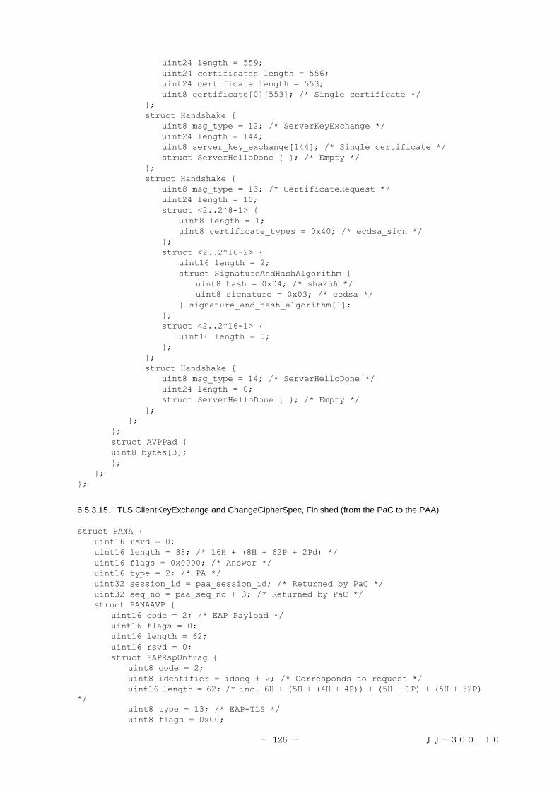
- 126 - JJ-300.10
uint24 length = 559;
uint24 certificates_length = 556;
uint24 certificate length = 553;
uint8 certificate[0][553]; /* Single certificate */
};
struct Handshake {
uint8 msg_type = 12; /* ServerKeyExchange */
uint24 length = 144;
uint8 server_key_exchange[144]; /* Single certificate */
struct ServerHelloDone { }; /* Empty */
};
struct Handshake {
uint8 msg_type = 13; /* CertificateRequest */
uint24 length = 10;
struct <2..2^8-1> {
uint8 length = 1;
uint8 certificate_types = 0x40; /* ecdsa_sign */
};
struct <2..2^16-2> {
uint16 length = 2;
struct SignatureAndHashAlgorithm {
uint8 hash = 0x04; /* sha256 */
uint8 signature = 0x03; /* ecdsa */
} signature_and_hash_algorithm[1];
};
struct <2..2^16-1> {
uint16 length = 0;
};
};
struct Handshake {
uint8 msg_type = 14; /* ServerHelloDone */
uint24 length = 0;
struct ServerHelloDone { }; /* Empty */
};
};
};
struct AVPPad {
uint8 bytes[3];
};
};
};
6.5.3.15. TLS ClientKeyExchange and ChangeCipherSpec, Finished (from the PaC to the PAA)
struct PANA {
uint16 rsvd = 0;
uint16 length = 88; /* 16H + (8H + 62P + 2Pd) */
uint16 flags = 0x0000; /* Answer */
uint16 type = 2; /* PA */
uint32 session_id = paa_session_id; /* Returned by PaC */
uint32 seq_no = paa_seq_no + 3; /* Returned by PaC */
struct PANAAVP {
uint16 code = 2; /* EAP Payload */
uint16 flags = 0;
uint16 length = 62;
uint16 rsvd = 0;
struct EAPRspUnfrag {
uint8 code = 2;
uint8 identifier = idseq + 2; /* Corresponds to request */
uint16 length = 62; /* inc. 6H + (5H + (4H + 4P)) + (5H + 1P) + (5H + 32P)
*/
uint8 type = 13; /* EAP-TLS */
uint8 flags = 0x00;

- 127 - JJ-300.10
struct TLSPlaintext{
uint8 type = 22; /* Handshake */
uint8 version[2] = {0x03, 0x03}; /* TLS 1.2 */
uint16 length = 4;
struct Handshake {
uint8 msg_type = 16; /* ClientKeyExchange */
uint24 length = 4;
struct ClientKeyExchange {
struct <0..2^16-1> {
uint16 length = 2;
uint8 bytes[1] = {0x30, 0x00};
} psk_identity;
} ;
} ;
} ;
struct TLSPlaintext{
uint8 type = 20; /* ChangeCipherSpec */
uint8 version[2] = {0x03, 0x03}; /* TLS 1.2 */
uint16 length = 1;
struct ChangeCipherSpec{
uint8 type = 1; /* ChangeCipherSpec */
};
};
struct TLSCiphertext {
uint8 type = 22; /* Handshake */
uint8 version[2] = {0x03, 0x03}; /* TLS 1.2 */
uint16 length = 32;
struct GenericAEADCipher {
struct CCMNonceExplicit {
uint64 seq_num;
};
struct CCMCipherText { /* inferred from draft-mcgrew-tls-aes-ccm
*/
struct Handshake { /* Encrypted */
uint8 msg_type = 20; /* Finished */
uint24 length = 12;
struct Finished {
uint8 verify_data[12];
;}
};
uint8 MAC[8]; /* Using AES_CCM_8 */
};
};
};
};
struct AVPPad {
uint8 bytes[2];
};
};
};
6.5.3.16. TLS ChangeCipherSpec, TLS Finished (from the PAA to the PaC)
struct PANA {
uint16 rsvd = 0;
uint16 length = 134; /* 16H + (8H + 49P + 0Pd) */
uint16 flags = 0x8000; /* Request */
uint16 type = 2; /* PA */
uint32 session_id = paa_session_id;
uint32 seq_no = paa_seq_no + 4; /* Increment sequence number */
struct PANAAVP {
uint16 code = 2; /* EAP Payload */
uint16 flags = 0;
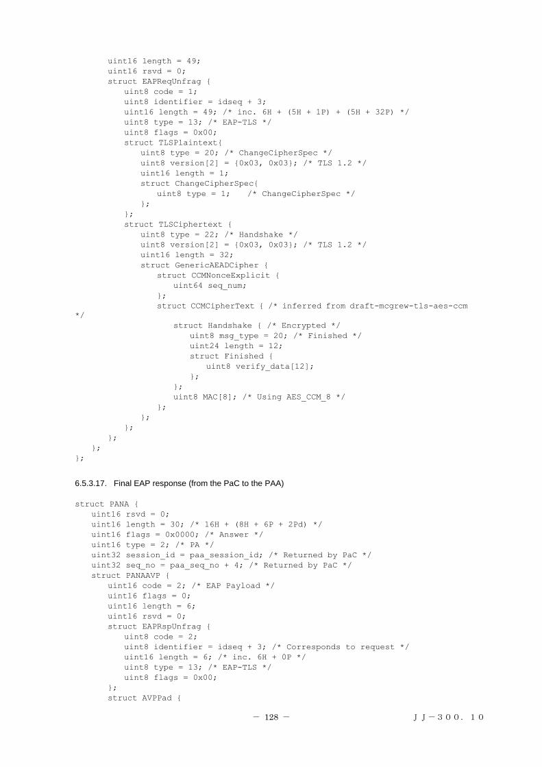
- 128 - JJ-300.10
uint16 length = 49;
uint16 rsvd = 0;
struct EAPReqUnfrag {
uint8 code = 1;
uint8 identifier = idseq + 3;
uint16 length = 49; /* inc. 6H + (5H + 1P) + (5H + 32P) */
uint8 type = 13; /* EAP-TLS */
uint8 flags = 0x00;
struct TLSPlaintext{
uint8 type = 20; /* ChangeCipherSpec */
uint8 version[2] = {0x03, 0x03}; /* TLS 1.2 */
uint16 length = 1;
struct ChangeCipherSpec{
uint8 type = 1; /* ChangeCipherSpec */
};
};
struct TLSCiphertext {
uint8 type = 22; /* Handshake */
uint8 version[2] = {0x03, 0x03}; /* TLS 1.2 */
uint16 length = 32;
struct GenericAEADCipher {
struct CCMNonceExplicit {
uint64 seq_num;
};
struct CCMCipherText { /* inferred from draft-mcgrew-tls-aes-ccm
*/
struct Handshake { /* Encrypted */
uint8 msg_type = 20; /* Finished */
uint24 length = 12;
struct Finished {
uint8 verify_data[12];
};
};
uint8 MAC[8]; /* Using AES_CCM_8 */
};
};
};
};
};
};
6.5.3.17. Final EAP response (from the PaC to the PAA)
struct PANA {
uint16 rsvd = 0;
uint16 length = 30; /* 16H + (8H + 6P + 2Pd) */
uint16 flags = 0x0000; /* Answer */
uint16 type = 2; /* PA */
uint32 session_id = paa_session_id; /* Returned by PaC */
uint32 seq_no = paa_seq_no + 4; /* Returned by PaC */
struct PANAAVP {
uint16 code = 2; /* EAP Payload */
uint16 flags = 0;
uint16 length = 6;
uint16 rsvd = 0;
struct EAPRspUnfrag {
uint8 code = 2;
uint8 identifier = idseq + 3; /* Corresponds to request */
uint16 length = 6; /* inc. 6H + 0P */
uint8 type = 13; /* EAP-TLS */
uint8 flags = 0x00;
};
struct AVPPad {

- 129 - JJ-300.10
uint8 bytes[2];
};
};
};
6.5.3.18. PANA Complete, EAP Success (from the PAA to the PaC)
struct PANA {
uint16 rsvd = 0;
uint16 length = 128; /* 16H + (8H + 4P) + (8H + 4P) + (8H + 4P) + (8H + 4P) +
(8H + (12H + 18P + 2Pd) + (8H + 16P) */
uint16 flags = 0xA000; /* Request, Complete */
uint16 type = 2; /* PA */
uint32 session_id = paa_session_id;
uint32 seq_no = paa_seq_no + 5; /* Increment sequence number */
struct PANAAVP {
uint16 code = 7; /* Result code */
uint16 flags = 0;
uint16 length = 4;
uint16 rsvd = 0;
uint32 result_code = 0; /* PANA_SUCCESS */
};
struct PANAAVP {
uint16 code = 2; /* EAP Payload */
uint16 flags = 0;
uint16 length = 4;
uint16 rsvd = 0;
struct EAPSuccess {
uint8 code = 3;
uint8 identifier = idseq + 4;
uint16 length = 4; /* inc. 4H + 0P */
};
};
struct PANAAVP {
uint16 code = 4; /* Key ID */
uint16 flags = 0;
uint16 length = 4;
uint16 rsvd = 0;
uint32 key_id = 0; /* Initial MSK */
};
struct PANAAVP {
uint16 code = 8; /* Session Lifetime */
uint16 flags = 0;
uint16 length = 4;
uint16 rsvd = 0;
uint32 sess_life = 0xFFFFFFFF; /* -1 = forever (136 years) */
};
struct PANAAVP {
uint16 code = 13; /* Encrypted Encapsulation */
uint16 flags = 0;
uint16 length = 32;
uint16 rsvd = 0;
struct PANAAVP {
uint16 code = 1; /* ZigBee Network Key */
uint16 flags = 1; /* Vendor specific */
uint16 length = 18;
uint16 rsvd = 0;
uint32 vendor_id = 37244; /* ZigBee Vendor ID */
struct ZBNWKKEY {
uint8 nwk_key[16];
uint8 nwk_key_idx;
uint8 auth_cntr;
};

- 130 - JJ-300.10
struct AVPPad {
uint8 bytes[2];
};
};
};
struct PANAAVP {
uint16 code = 1; /* Auth */
uint16 flags = 0;
uint16 length = 16;
uint16 rsvd = 0;
uint8 auth[16]; /* Hash */
};
};
6.5.3.19. PANA Complete (from the PaC to the PAA)
struct PANA {
uint16 rsvd = 0;
uint16 length = 54; /* 16H + (8H + 4P) + (8H + 16P) */
uint16 flags = 0x2000; /* Answer, Complete */
uint16 type = 2; /* PA */
uint32 session_id = paa_session_id; /* Returned by PaC */
uint32 seq_no = paa_seq_no + 5; /* Returned by PaC */
struct PANAAVP {
uint16 code = 4; /* Key ID */
uint16 flags = 0;
uint16 length = 4;
uint16 rsvd = 0;
uint32 key_id = 0; /* Initial MSK */
};
struct PANAAVP {
uint16 code = 1; /* Auth */
uint16 flags = 0;
uint16 length = 16;
uint16 rsvd = 0;
uint8 auth[16]; /* Hash */
};
};
6.6. Annex-2
This section describes changes to the specifications for each layer that are required for implementation for 920MHz
PHY. The corresponding parameter and other values described above shall be overwritten with the values specified in
this section.
6.6.1. Physical layer
For 920MHz PHY, the modulation scheme shall be specified to FSK and the data rate shall be set to 100kbit/s,
which are specified in IEEE 802.15.4g-2012 [802.15.4], and other items shall be treated as options. A preamble length
of at least 12 bytes is recommended in consideration of the reception using a diversity antenna.
The PSDU size shall be up to 254 bytes. While transmission and reception using CSM is specified in IEEE
802.15.4g-2012 [802.15.4], the use of CSM shall be optional in this specification. While IEEE 802.15.4g-2012
[802.15.4] specifies MR-FSK data whitening is optional, MR-FSK data whitening shall be used in this specification.

- 131 - JJ-300.10
6.6.2. Data link layer
Since the PSDU size shall be up to 254 bytes, the 2-octet FCS shall be used, and the use of the 4-octet FCS shall be
optional.
While IEEE 802.15.4g-2012 [802.15.4] specifies that multi-PHY management (MPM) is mandatory when 1% duty
cycle is exceeded, MPM shall be optional in this specification.
6.6.3. Network layer
6.6.3.1. Multicast
While [EL] specifies that FF02:0:0:0:0:0:0:1 shall be used for the multicast address, the address shall be replaced
with the following address:
Unicast address
FF02:0:0:0:0:0:0:1
FF03:0:0:0:0:0:0:1
FF05:0:0:0:0:0:0:1
FF03:0:0:0:0:0:0:2
FF05:0:0:0:0:0:0:2
If a multicast request is transmitted for a specification which requires a multicast response such as the property value
notification service according to [EL], communication traffic increases as the number of terminals increases.
Since ZigBee IP assumes multihop communication, it may be assumed that multicast communication is required to
be made to broader scope.
For this reason, it is desirable to set appropriate scope for the multicast destination address.
6.6.3.2. RPL attribute
The minimum value (MIN_RPL_INSTANCE_COUNT) for the RPL Instance shall be 1.
6.6.3.3. Transport
For ECHONET Lite [EL] application data communication, UDP packets shall be used for transmission and
reception, and TCP packets shall be optional. The destination port number of UDP frames shall always be 3610 as
described in [EL].
6.6.4. Application layer
For the application layer, ECHONET Lite [EL] shall be used. The nodes compliant with the specifications for this
system shall support all required functions specified in [EL].
[EL] shall provide the following services:
・ Detection of functional units (ECHONET objects) employed by the other nodes in the network
・ Acquisition of parameters and statuses (ECHONET properties) the other nodes have
・ Configuration of parameters and statuses for the other nodes
・ Notification of parameters and statuses the local node has

- 132 - JJ-300.10
6.7. Annex-3
This section clarifies the IEEE 802.15.4/4g functions that should be supported.
The "Status in IEEE standard" column indicates specifications in IEEE 802.15.4/4g. M means a mandatory function
and O means an optional function. The "Use of system B" column indicates whether to use the relevant item in system
B. Y means a required function, N means a function not required, and O means an optional function. O.x means that
only one item of the same type is to be used.
6.7.1. Device specifications
The use specifications of the functions related to devices in IEEE 802.15.4/4e/4g are shown below.
Table 6-26: Functional device types
Number Description Reference section in
standard
Status in IEEE
standard Use of system B
FD1 Parent device [802.15.4] 5.1 O.1 O.1
FD2 Child device [802.15.4] 5.1 O.1 O.1
FD3 Support of 64-bit address [802.15.4] 5.2.1.1.6 M Y
FD4 Short address assignment [802.15.4] 5.1.3.1 FD1: M FD1: Y
FD5 Support of short address [802.15.4] 5.2.1.1.6 M Y
FD8 15.4g-compatible device [802.15.4g] 8.1 O.3 Y
6.7.2. Physical layer specifications
The use specifications of the functions related to the physical layer are shown below.
Table 6-27: PHY functions and PHY packets
Number Description Reference section in
standard
Status in IEEE
standard Use of system B
PLF1 Energy detection [802.15.4] 8.2.5 FD1: M FD1: Y
PLF2 Link quality indication [802.15.4] 8.2.6 M Y
PLF3 Channel selection [802.15.4] 8.1.2 M Y
PLF4 Clear channel assessment [802.15.4] 8.2.7 M Y
PLF4.1 Determination of CCA with field
intensity
[802.15.4] 8.2.7 O.2 Y
PLF4.2 Determination of CCA with carrier
sense
[802.15.4] 8.2.7 O.2 N
PLF4.3 Concurrent use of 1 and 2 [802.15.4] 8.2.7 O.2 N
PLP1 PSDU size [802.15.4g] 9.2 FD8: M Up to about 255
bytes is
recommended.

- 133 - JJ-300.10
Table 6-28: Radio frequency (RF)
Number Description Reference section in
standard
Status in IEEE
standard Use of system B
RF12 SUN PHYs
RF12.1 MR-FSK [802.15.4g] 16.1 FD8: M Y
RF12.2 MR-OFDM [802.15.4g] 16.2 FD8: O N
RF12.3 MR-O-QPSK [802.15.4g] 16.3 FD8: O N
RF12.4 MR-FSK-Generic PHY [802.15.4g] 8.1.2.7.2 RF12.1: O N
RF12.5 Transmit and receive of extended
beacons with shared signals
[802.15.4g] 8.1a FD1, 8,
MLF15: M
N
RF12.6 Selection of frequency used [802.15.4g] 8.1 FD8: M 920MHz
RF13 SUN PHY operating modes
RF13.4 50kbit/s and 100kbit/s supported
when 920MHz is used
[802.15.4g] 16.1 FD8: M Use 100kbit/s.
RF13.5 200kbit/s and 400kbit/s supported
when 920MHz is used
[802.15.4g] 16.1 FD8: O N
RF14 MR-FSK options [802.15.4g]
RF14.1 MR-FSK FEC [802.15.4g] 16.1.2.4 O N
RF14.2 MR-FSK interleaving [802.15.4g] 16.1.2.5 O N
RF14.3 MR-FSK data whitening
(scrambling)
[802.15.4g] 16.1.3 O Y
RF14.4 Data rate changed in packet units [802.15.4g] 16.1.4 O N
Table 6-29: PHY
Item Use of system B Remarks
Modulation scheme GFSK
Data rate 100kbit/s
Transmission power 20 mW or less
Frequency channel Channels of Nos. 33 to 60 specified in
ARIB with bundling of an odd
channel and the next even channel
Channels of Nos. 33 to 38 are also used by
systems with a transmission power of
250mW.
Occupied bandwidth 400kHz (with 2 channel bundling)
Transmission preamble
length
At least 12 bytes
6.7.3. Data link layer specifications
The use specifications of the functions related to the data link layer are shown below.
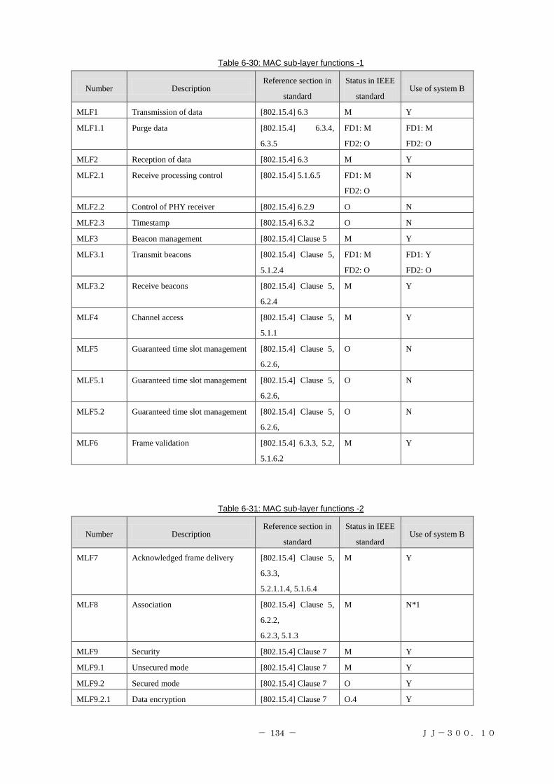
- 134 - JJ-300.10
Table 6-30: MAC sub-layer functions -1
Number Description Reference section in
standard
Status in IEEE
standard Use of system B
MLF1 Transmission of data [802.15.4] 6.3 M Y
MLF1.1 Purge data [802.15.4] 6.3.4,
6.3.5
FD1: M
FD2: O
FD1: M
FD2: O
MLF2 Reception of data [802.15.4] 6.3 M Y
MLF2.1 Receive processing control [802.15.4] 5.1.6.5 FD1: M
FD2: O
N
MLF2.2 Control of PHY receiver [802.15.4] 6.2.9 O N
MLF2.3 Timestamp [802.15.4] 6.3.2 O N
MLF3 Beacon management [802.15.4] Clause 5 M Y
MLF3.1 Transmit beacons [802.15.4] Clause 5,
5.1.2.4
FD1: M
FD2: O
FD1: Y
FD2: O
MLF3.2 Receive beacons [802.15.4] Clause 5,
6.2.4
M Y
MLF4 Channel access [802.15.4] Clause 5,
5.1.1
M Y
MLF5 Guaranteed time slot management [802.15.4] Clause 5,
6.2.6,
O N
MLF5.1 Guaranteed time slot management [802.15.4] Clause 5,
6.2.6,
O N
MLF5.2 Guaranteed time slot management [802.15.4] Clause 5,
6.2.6,
O N
MLF6 Frame validation [802.15.4] 6.3.3, 5.2,
5.1.6.2
M Y
Table 6-31: MAC sub-layer functions -2
Number Description Reference section in
standard
Status in IEEE
standard Use of system B
MLF7 Acknowledged frame delivery [802.15.4] Clause 5,
6.3.3,
5.2.1.1.4, 5.1.6.4
M Y
MLF8 Association [802.15.4] Clause 5,
6.2.2,
6.2.3, 5.1.3
M N*1
MLF9 Security [802.15.4] Clause 7 M Y
MLF9.1 Unsecured mode [802.15.4] Clause 7 M Y
MLF9.2 Secured mode [802.15.4] Clause 7 O Y
MLF9.2.1 Data encryption [802.15.4] Clause 7 O.4 Y

- 135 - JJ-300.10
MLF9.2.2 Frame integrity [802.15.4] Clause 7 O.4 Y
MLF10.1 Energy detection scanning [802.15.4] 5.1.2.1,
5.1.2.1.1
FD1: M
FD2: O
FD1: Y
FD2: O
MLF10.2 Active scanning [802.15.4] 5.1.2.1.2 FD1: M
FD2: O
Y
MLF10.3 Passive scanning [802.15.4] 5.1.2.1.2 M Y
MLF10.4 Orphan scanning [802.15.4] 5.1.2.1,
5.1.2.1.3
M O*2
MLF11 Superframe structure control [802.15.4] 5.1.1.1 FD1: O N
MLF12 Support of superframe structure [802.15.4] 5.1.1.1 O N
MLF13 Store one transaction [802.15.4] 5.1.5 FD1: M Y
MLF15 Multiple PHY management [802.15.4g] 5.1.9 FD8: M N
*1: Not used since done in an upper layer.
*2: May not be used since optional in an upper layer.
Table 6-32: MAC frames
Number Description Reference section in
standard
Status in IEEE standard Use of system
B Transmit Receive
MF1 Beacon [802.15.4] 5.2.2.1 FD1: M M Y
MF2 Data [802.15.4] 5.2.2.2 M M Y
MF3 ACK [802.15.4] 5.2.2.3 M M Y
MF4 Command [802.15.4] 5.2.2.4 M M Y
MF4.1 Association request [802.15.4] 5.2.2.4, 5.3.1 M FD1: M N*1
MF4.2 Association response [802.15.4] 5.2.2.4, 5.3.2 FD1: M M N*1
MF4.3 Disassociation notification [802.15.4] 5.2.2.4, 5.3.3 M M N*1
MF4.4 Data request [802.15.4] 5.2.2.4, 5.3.4 M FD1: M Y
MF4.5 PAN ID conflict
notification
[802.15.4] 5.2.2.4, 5.3.5 M FD1: M N
MF4.6 Orphaned device
notification
[802.15.4] 5.2.2.4, 5.3.6 M FD1: M O*2
MF4.7 Beacon request [802.15.4] 5.2.2.4, 5.3.7 FD1: M FD1: M Y*3
MF4.8 Parent device
reconfiguration
[802.15.4] 5.2.2.4, 5.3.8 FD1: M M Y
MF4.9 GTS request [802.15.4] 5.2.2.4, 5.3.9 MLF5: O MLF5: O N
MF5 32-bit FCS [802.15.4g] 5.2.1.9 FD6: M FD6: M Y*4
*1: Not used since done in an upper layer.
*2: May not be used since optional in an upper layer.
*3: Can also be used for a child device (clarifies an FD2 specification not included in the reference standard).
*4: Use 16-bit FCS when the PSDU size does not exceed 255 octets.

- 136 - JJ-300.10
7. System C
7.1. Overview
This chapter defines the physical layer part, data link layer part, and interface part (provided as an option) that are
required for ECHONET Lite communication between a coordinator and host only using IEEE802.15.4/4e/4g (Sections
7.3 to 7.9) and specifies the recommended specification for configuring a single-hop network using EHONET Lite
(Section 7.10).
The physical and data link layer parts are composed of selected functions specified in the IEEE802.15.4/4e/4g
standard. The interface part is used to connect the ECHONET Lite application part directly to the data link layer and
physical layer since the following case is assumed: The addressing architecture specified in the ECHONET Lite
application part differs from that specified in the data link layer part. The part transmits transmission data from the
ECHONET Lite application part to the destination device using the data link and physical layers and transmits
reception data from the destination device to the ECHONET Lite application part. Figure 7-1 shows the location of
each part. Figure 7-2 shows the layer structure.
.In this chapter, "M" means a mandatory function in the standards [802.15.4], [802.15.4e], and [802.15.4g], "O"
means an optional function, "Y" means a function required for operating ECHONET Lite, and "N" means a function
not required. Specifications and procedures for certification and interoperability tests are provided by [Wi-SUN-PHY],
[Wi-SUN-MAC], [Wi-SUN-IF], [Wi-SUN-CTEST], and [Wi-SUN-ITEST].
(*1: Not required in case addressing architectures are the same between the ECHONET Lite application part and data
link layer part.)
Figure 7-1 Scope defined by this chapter
Scope of this section
ECHONET-Lite
application part
MAC part
(IEEE802.15.4/4e)
PHY part
(IEEE802.15.4g)
Interface part
Device 1 application
Device 1
ECHONET-Lite
application part
MAC part
(IEEE802.15.4/4e)
PHY part
(IEEE802.15.4g)
Interface part
Device 2 application
Device 2
*1 *1

- 137 - JJ-300.10
7.2. Protocol stack
The protocol stack for a node specified for this system is shown in Figure 7-2.
(*1: Not required in case addressing architectures are the same between the ECHONET Lite application part and data
link layer part.)
Figure 7-2 Layer structure defined by this chapter
The physical layer provides the following service as far as it is used in this system:
・ Up-to-2047-octet PSDU exchange (Note that the system recommends 255 octets or less as described
below.)
The data link (MAC) layer provides the following services as far as it is used in this system:
・ Discovery of an IEEE802.15.4 PAN in radio propagation range
・ Support of low-energy hosts that can change its status between sleep and active states
・ Security functions that include encryption, manipulation detection, and replay attack protection (Note that
key management is not performed by this layer.)
The application layer provides the following services:
・ Detection of functional units (ECHONET objects) employed by the other nodes in the network
・ Acquisition of parameters and statuses (ECHONET properties) the other nodes have
・ Configuration of parameters and statuses for the other nodes
・ Notification of parameters and statuses the local node has
Layer 1PHY part
(PHY profiles based on IEEE 802.15.4g)
MAC part
(MAC profiles based on IEEE 802.15.4/4e)
Application layer
(ECHONET Lite)
Interface part
Layer 2
Layer 5-7
*1

- 138 - JJ-300.10
7.3. Physical layer part
See Section 5.3.
7.4. Data link layer (MAC layer) part
See Section 5.4.
7.5. Interface part
7.5.1. Overview
The interface part shall be implemented between the ECHONET Lite application part and physical layer part/data
link layer part and provide a function to communicate between them, assuming that the addressing architecture
specified in the ECHONET Lite application part differs from that specified in the data link layer part. This interface
can improve frame utilization efficiency by reducing overhead when IP is used.
7.5.2. Requirements
(1) The interface part shall specify unique destination addresses when used. It also shall configure an ECHONET
Interface header by specifying the source address and Interface Type. In this case, the Interface Type shall be
0xEC00.
(2) The interface part shall know the address configuration used in the MAC part in advance. The address
configuration needs to be an EUI-64-bit address.
(3) The interface part must convert the unique destination address specified in the interface part according to the
addressing architecture used in the MAC part and transmit it to the MAC part.
(4) When the MAC address transmitted from the ECHONET Lite application part is a multicast MAC address, the
interface part shall instruct the MAC part to do broadcast transmission.
7.6. Application layer
As the application layer, ECHONET Lite [EL] shall be used and all required functions specified in [EL] shall be
supported.
7.7. Security
There are the following two ways for ensuring security in the non-IP mode. Either way shall be implemented as a
requirement.
Data encryption in the IEEE 802.15.4 MAC part (required when the interface part is not used)
Data encryption in the interface part
AES-CCM and/or AES-GCM shall be implemented as the encryption scheme for data encryption in the interface
part [EL], [CMAC], [AES-CCM], [AES-GCM]. To use AES-CCM/GCM, MIC (message integrity code) or AAD
(Additional Authenticated Data) must be used. For AES-CCM data encryption in the IEEE 802.15.4 MAC part, the
MIC must be contained in the IEEE 802.15.4 MAC frame described in document [1]. On the other hand, for data
encryption in the interface part, the MIC shall be contained in the security header described in Section 4.4.6.5.

- 139 - JJ-300.10
7.8. Device ID
As an optional function in the non-IP mode, the device ID assigned to each ECHONET Lite-compatible device may
be used. This device ID may be used during MAC address initialization and other processes. In this case, there are two
types of payload handled: Information payload and setting payload. Information payload is used for ECHONET Lite
data exchange and setting payload is used for device ID exchange.
7.9. Frame formats
This section describes frame formats used for this system. The frame format differs depending on whether the
interface part is used. To identify a frame format in a receiving node, The specification separately provided for
coexistence between systems is used.
7.9.1. When the interface part is used
7.9.1.1. When data encryption in the MAC part is used
Sample frame formatting procedures for using data encryption in the MAC part are shown in Figure 7-3 to Figure
7-5. In these figures, the destination and source MAC addresses differ between the ECHONET Interface header and
IEEE 802.15.4 MAC header. These two addresses can be omitted.
ECHONET Lite Payload
Variable
Figure 7-3: ECHONET Lite payload
Destination
MAC address
Source
MAC addressInterface Type
ECHONET Interface header
ECHONET Lite Payload
2Byte8Byte 8Byte Variable
Figure 7-4: Frame configured in the interface part
Destination
MAC address
Source
MAC addressInterface Type
ECHONET Interface header
ECHONET Lite Payload FCSIEEE802.15.4 header
2Byte2Byte8Byte 8Byte VariableVariable
Figure 7-5: IEEE 802.15.4 frame configured in the MAC part
7.9.1.2. When data encryption in the interface part is used
Sample frame formatting procedure for using data encryption in the interface part are shown in Figure 7-6 to
Figure 7-8. In these figures, the destination and source MAC addresses differ between the ECHONET Interface
header and IEEE 802.15.4 MAC header. These two addresses can be omitted.

- 140 - JJ-300.10
ECHONET Lite Payload
Variable
Figure 7-6: ECHONET Lite payload
Destination
MAC address
Source
MAC addressInterface Type
ECHONET Interface header
ECHONET Lite Payload
2Byte8Byte 8Byte Variable9Byte
Security header MIC
8Byte
Figure 7-7: Frame configured in the interface part
IEEE802.15.4 header
Variable
Destination
MAC address
Source
MAC addressInterface Type
ECHONET Interface header
ECHONET Lite Payload
2Byte8Byte 8Byte Variable9Byte
Security header FCS
2Byte
MIC
8Byte
Figure 7-8: IEEE 802.15.4 frame configured in the MAC part
7.9.1.3. When the device ID option and data encryption in the interface part are used
This section gives figures that show a procedure for converting information payload from the ECHONET Lite
application to the MAC part frame when the device ID option and data encryption in the interface part are used. In
these figures, the destination and source MAC addresses differ between the ECHONET Interface header and IEEE
802.15.4 MAC header. These two addresses can be omitted.
ECHONET Lite Payload
Variable
Figure 7-9: ECHONET Lite payload
Destination
MAC address
Source
MAC addressInterface Type
ECHONET Interface header
Data Payload
2Byte8Byte 8Byte Variable9Byte
Security header MIC
8Byte
Protocol info
1Byte
Figure 7-10: Frame configured in the interface part
IEEE802.15.4 header
Variable
FCS
2Byte
Destination
MAC address
Source
MAC addressInterface Type
ECHONET Interface header
Data Payload
2Byte8Byte 8Byte Variable9Byte
Security header MIC
8Byte
Protocol info
1Byte
Figure 7-11: IEEE 802.15.4 frame configured in the MAC part

- 141 - JJ-300.10
7.9.1.4. Frame elements
7.9.1.4.1. ECHONET Lite payload
ECHONET Lite information payload generated in the ECHONET Lite application part
7.9.1.4.2. ECHONET Interface header
The ECHONET Interface header is generated uniquely in the interface part. Figure 7-12 shows the structure.
Byte # Bit7 Bit6 Bit5 Bit4 Bit3 Bit2 Bit1 Bit0
0
1
2
3
4
5
6
7
8
9
10
11
12
13
14
15
16
17
Source MAC address
Interface Type
Destination MAC address
Figure 7-12: ECHONET Interface header format
(a) Destination address
Destination address determined in collaboration between the ECHONET Lite application part and interface part
(b) Source address
Source MAC address. This address is configured based on the address configuration in the MAC part by the
interface part.
(c) Interface Type
0xEC00: Interface Type for ECHONET Lite
7.9.1.4.3. IEEE 802.15.4 header
Header for transmission and reception that is generated by the MAC part
7.9.1.4.4. FCS (Frame check sequence)
Frame check sequence generated in the MAC part
7.9.1.4.5. Security header
The security header is used to define information related to encryption for transmission data. Figure 7-13 shows the
format.

- 142 - JJ-300.10
Byte # Bit7 Bit6 Bit5 Bit4 Bit3 Bit2 Bit1 Bit0
0
1
2
3
4
5
6
7
8
Nonce:Reset information
Nonce:Message counter
Security key ID
Figure 7-13: Security header format
(a) Security key ID
Identifier corresponding to the encryption key used
(b) Nonce (byte# 1-8)
For nonce, a unique value is configured for each transmission data and encrypted together with data. A nonce
consists of the following elements:
Reset information (byte# 1-4): Specifies an incremental value used for each reset of the device.
Message counter (byte# 5-8): Counter for the number of messages transmitted
7.9.1.4.6. MIC (message integrity code)
Code used for AES-CCM encryption
7.9.1.4.7. Protocol info
Protocol info indicates the protocol type of data to be transmitted, which is used when a unique device ID is defined.
Figure 7-14 shows the format.
Byte # Bit7 Bit6 Bit5 Bit4 Bit3 Bit2 Bit1 Bit0
0 Protocol classVersion info
Figure 7-14: Format of protocol info
(a) Version info: 4 bits long. Up to 16 versions can be specified.
(b) Protocol class: Used for identifying setting payload and information payload.
0000: Information payload, 0001: Setting payload
7.9.1.4.8. Data payload
Data payload carries either information payload or setting payload containing a device ID. Information payload or
setting payload is selected according to the protocol class value. The format is shown below.

- 143 - JJ-300.10
Byte # Bit7 Bit6 Bit5 Bit4 Bit3 Bit2 Bit1 Bit0
1
2
3
4
5
6
7
8
ECHONET Lite Payload (Variable)
MIC(Message Integrity Code)
Figure 7-15: Information payload format
Byte # Bit7 Bit6 Bit5 Bit4 Bit3 Bit2 Bit1 Bit0
0
1
2
3
4
5
6
7
8
9
10
11
12
13
14
15
16
MIC(Message Integrity Code)
Message identifier
Device ID
Figure 7-16: Setting payload format
(a) Message identifier: Used for indicating a setting request or response.
00000000: Setting request
00000001: Setting response
7.9.2. When the interface part is not used
When the ECHONET Lite application part directly handles IEEE 802.15.4 MAC addresses, the interface part is
unnecessary. Sample frame formats used when the interface part is not used are shown in Figure 7-17 and Figure
7-18. When the interface part is not used, the IEEE 802.15.4 header is located just before ECHONET Lite Payload.

- 144 - JJ-300.10
Variable
ECHONET Lite Payload
Figure 7-17: ECHONET Lite payload
Variable Variable 2 Byte
IEEE 802.15.4 header
ECHONET Lite Payload FCS
Figure 7-18: IEEE 802.15.4 frame configured in the MAC frame
7.10. Recommended specification for configuring a single-hop network
7.10.1. Overview
This section describes the recommended specification for constructing a single-hop network using ECHONET Lite
in system C. Other specifications are not excluded as far as system C specification is conformed.
Nodes based on the specification in this section construct a single-hop network where a coordinator is centered. And,
with assuming a gateway connection provided by the application layer as the connection measure to external networks,
a closed network is assumed inside this system. On those assumptions, the indoor network construction using
ECHONET Lite provides expandability as well as feasibility.
7.10.2. Construction of a new network
Once turned on, a coordinator constructs a new network compliant with this system specification. The network
construction is conducted by successive steps of (1) data link layer configuration and (2) security configuration. An
overview of the network construction procedure is shown in Figure 7-19.
コーディネータ起動コーディネータ起動コーディネータ起動
チャネルの選択チャネルの選択チャネルの選択(1)(1)
PAN ID の決定PAN ID PAN ID の決定の決定(2)(2)
データリンク層データリンク層の設定の設定
セキュリティの設定セキュリティの設定
Figure 7-19: Overview of network construction procedure
7.10.2.1. Data link layer configurations
Once turned on, a coordinator constructs an IEEE 802.15.4 PAN. A detailed procedure for PAN construction is as
follows.
The coordinator first selects a channel to use. The channel selection is conducted via ED scanning or active scanning.
In the selection, a channel with less interference to the other systems is more preferable. (Step 1)
Turn on coordinator
Select channel
Determine PAN ID
Data link layer configurations
Security configurations

- 145 - JJ-300.10
Finally, the coordinator selects a PAN ID that is not occupied by any PAN on the channel selected in Step 1, and
defines it as the PAN ID to be used in the network the coordinator manages. For this system, the following procedure is
not specified: How the coordinator selects a PAN ID that is not occupied by any PAN on the channel selected in Step 1
as the PAN ID of the local network. (Step 2)
After the previous steps, the coordinator completes the PAN construction using the determined radio channel and PAN
ID.
7.10.2.2. Security configurations
The coordinator conducts security configurations following data link layer configurations. Security technologies
employed in the constructed network should be selected according to the application requirements. This system
specification does not describe a specific procedure for security configurations conducted by the coordinator.
7.10.3. Joining in a network
Once turned on, a new host tries to join the existing network compliant with this system. The joining procedure by
the host includes (1) data link layer configuration and (2) security configuration just in a same manner as the network
construction by a coordinator. An overview of the procedure for joining the existing network by a new host is shown in
Figure 7-20.
新規ホスト起動新規ホスト起動新規ホスト起動
ネットワークの検出ネットワークの検出ネットワークの検出
参加するネットワークの選択参加するネットワークの選択参加するネットワークの選択
(1)(1)
(2)(2)
(4)(4)
コーディネータコーディネータコーディネータ
アソシエーションアソシエーションアソシエーション(3)(3)
機器認証機器認証機器認証
Figure 7-20: Overview of network joining procedure
7.10.3.1. Data link layer configurations
Once turned on, first, a new host detects an existing IEEE 802.15.4 PAN around it. The PAN detection procedure is
as follows: The new host transmits a beacon request command message specified in [802.15.4] to all available radio
channels specified in [802.15.4] and [T108]. A coordinator that receives the message transmits a beacon frame as a
response. The new host receives the beacon. Moreover, the new host can recognize the radio channel and PAN ID
employed by the coordinator, as a result of this procedure. (Step 1)
If only one PAN is detected in Step 1, the host proceeds to the next step for that PAN. If multiple PANs are detected,
the host selects one of them and proceeds to the next step. Which PAN the host selects depends on the implementation.
(Step 2)
The new host conducts association specified in IEEE 802.15.4 for the PAN selected in Step 2. (Step 3)
If the new host fails to join the selected PAN as the result of association for the PAN, for example, due to connection
rejection by the coordinator, the host is recommended to retry the joining procedure from Step 1 or 2. In the retry
procedure, the host should select a network other than that the host fails to join.
Turn on new host Coordinator
Detect network
Select network to join
Association
Authenticate device

- 146 - JJ-300.10
7.10.3.2. Security configurations
After the completion of joining the IEEE802.15.4 PAN, the new host conducts security configurations with the
coordinator. Since security technologies employed in the constructed network are out of scope of this system
specification, this system specification does not describe a specific procedure for security configurations conducted
with network joining.
7.10.4. Specifications for the device/physical layer/MAC layer to implement the recommended specification
See Section 5.8.4.