john ging transmission access planning
TRANSCRIPT

Harmonics Progress
John Ging
Transmission Access Planning

What has happened since
the last LG meeting?
• Background harmonic data was recorded at
various stations for model building and
verification
• Publication of 1st Harmonic Information Note – Covers basic theory and background information on the topic
– 2nd Information Note on Harmonics Policy due imminently
• Studies of some South West clusters completed – Harmonic Voltage Limits and Impedance loci were communicated with the
relevant customers

Current work on Harmonics
• Organising a harmonics workshop for stakeholders – Expected Mid October
• Reviewing Charging Policy for harmonics issues – Information note expected to issue in the coming weeks
• Evaluating suitability of harmonics clause in the Grid Code – Discussion at GCRP
• Further Studies for select nodes with significant cable build are underway – South West, North West
– More studies will be prioritised after offer acceptance and modifications received

Next Steps
• Exchange disturbance recorder data with the DSO – 38kV recording data on MV side and 110kV data on HV side of transformers will
aid mutual model validation
• Identify “Designated Study Areas” – Priority regions due to high existing background distortion
• Communication with all applicants in problem regions – Explore issues on a cluster basis
• Complex analysis is required for any application in the proximity of Designated Study Areas or if a harmonic problem has been identified – The processing of associated offers will necessitate bespoke timelines
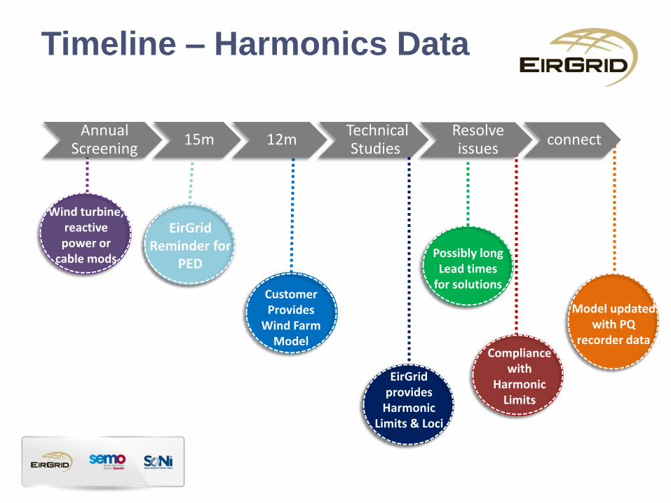
Timeline – Harmonics Data
Annual Screening
15m 12m Technical
Studies Resolve issues
connect
Customer Provides
Wind Farm Model
Possibly long Lead times
for solutions
EirGrid provides
Harmonic Limits & Loci
Wind turbine, reactive power or
cable mods
EirGrid Reminder for
PED
Model updated with PQ
recorder data Compliance
with Harmonic
Limits
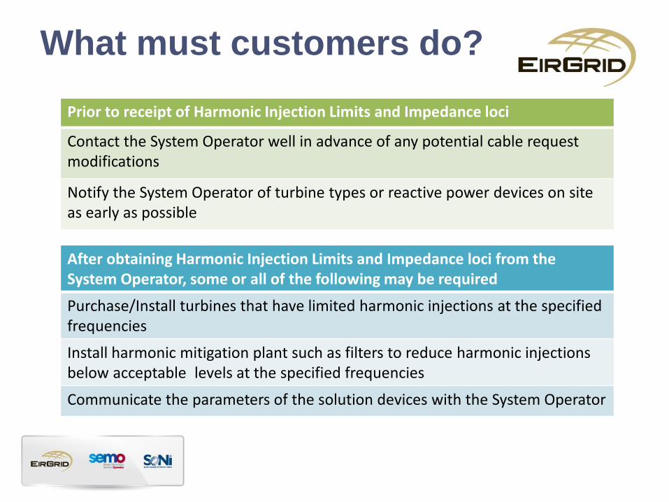
What must customers do?
Prior to receipt of Harmonic Injection Limits and Impedance loci
Contact the System Operator well in advance of any potential cable request modifications
Notify the System Operator of turbine types or reactive power devices on site as early as possible
After obtaining Harmonic Injection Limits and Impedance loci from the System Operator, some or all of the following may be required
Purchase/Install turbines that have limited harmonic injections at the specified frequencies
Install harmonic mitigation plant such as filters to reduce harmonic injections below acceptable levels at the specified frequencies
Communicate the parameters of the solution devices with the System Operator

More details can be found on our
Harmonics Information page
http://www.eirgrid.com/customers/gridconnections/harmonics/

Liaison Group – 3 September 2013
Marie Hayden
Charging for Harmonics

What is Connection Charging
• Recovery of “shallow” asset capital costs
associated with customer connections.
• Focused on transmission assets required up to
the meshed system.
• Governed by a number of policy documents
which set out high level principles for the
assigning of costs.

Connection Charging: basics
• Focused on determining causation and drivers of
specific works.
• Charging is applied on a Least Cost Chargeable
(LCC) basis – charge may not correspond to the
actual build.
• Assets which are not driven exclusively by a given
customer/subgroup are considered “deep” and are
recovered via TUoS tariffs.
• Rebates are payable where customers connect to
assets which were funded by pre-connected parties.

Harmonics issues in a charging context • Difficult to assign causation to specific customers –
suggests “deep” from a charging perspective.
• Harmonic issues often driven by customer requests (cable), policy permits charging for deeps in such circumstances.
• If harmonic solutions are optimised on a geographic basis, are deep in the system and mitigate harmonics for a number of applicants, how do we assign costs.
• First mover – pay for harmonic solution, free rider issue. Impossible to allocate rebates for deep assets, how do you quantify system benefits and account for these?

Considerations
• The charging approach needs to: – Be fair and proportional.
– Send a signal about the cost that cable requests impose on the system.
– Be relatively simple to apply, not requiring a suite of “charging” power quality
studies.
– Work in general, not just solve issues with current Offer Process
modifications.

Options being considered

Option 1: Charge for the technical
solution identified
Pros:
• Entirely cost reflective.
Cons:
• Extremely complex from a charging perspective.
• Would require additional “charging” power
quality studies to determine “drivers” and the
extent to which individual subgroups/applicants
are contributing to optimised solutions.
• Rebating issues: first mover disadvantage.

Option 2: Apply a Least Cost approach
• Apply an LCC type approach – e.g. charge for a filter bank at the point of connection to the meshed system where the connection exceeds harmonics limits.
Pros:
• Consistent with the LCC principle, pay for the lowest cost solution to the problem, regardless of what is ultimately installed.
• Clear and transparent approach.
Cons:
• Rebating issues – we charge and rebate on actual build, free rider issue. (include filter bank in cable charge?)
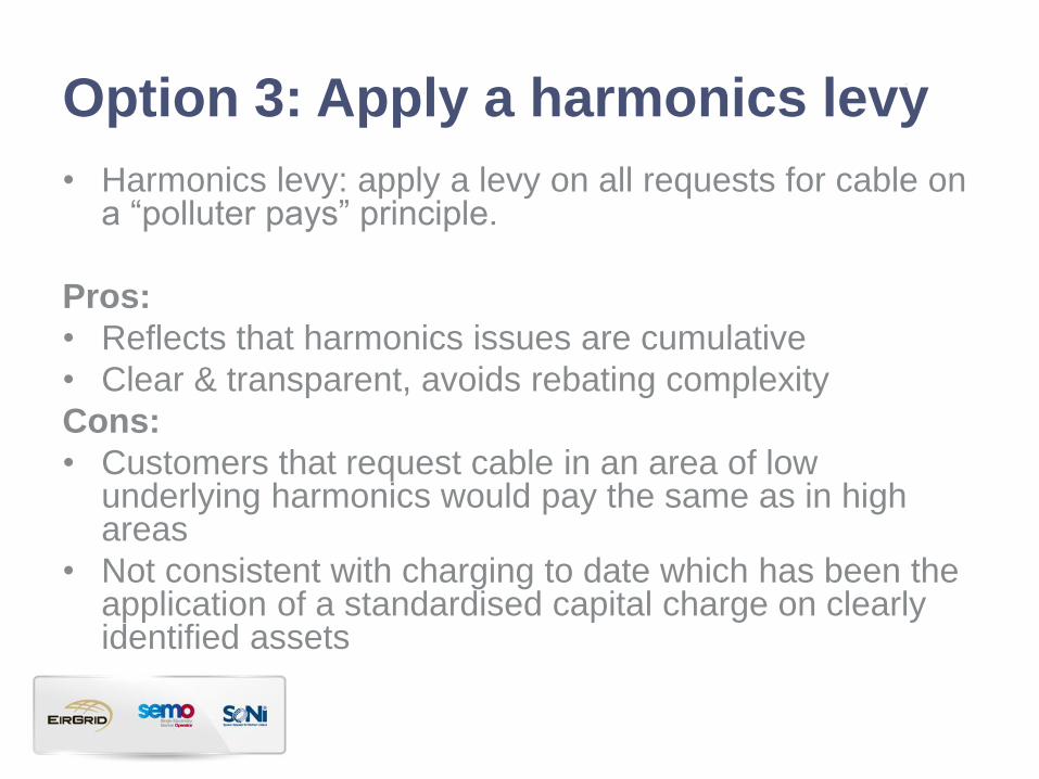
Option 3: Apply a harmonics levy
• Harmonics levy: apply a levy on all requests for cable on a “polluter pays” principle.
Pros:
• Reflects that harmonics issues are cumulative
• Clear & transparent, avoids rebating complexity
Cons:
• Customers that request cable in an area of low underlying harmonics would pay the same as in high areas
• Not consistent with charging to date which has been the application of a standardised capital charge on clearly identified assets

Next steps
• We would like to receive comments on each of the options presented here
• We will consider these comments and finalise the policy approach
• We will communicate the policy approach to industry and then capture in the next revision of charging policy papers
• Timeline – Linked to overall Harmonics Action Plan
• Should be completed before next LG meeting


Special Protection Schemes
Tom Gallery
Transmission Access Planning

Overview of Presentation
– Introduction to Special Protection Schemes (SPS)
– EirGrid Special Protection Scheme (SPS) Policy
– Examples of SPS schemes
– Future Work

Introduction
A special Protection Scheme is defined as: An automatic protection system designed to detect abnormal or predetermined system conditions, and take corrective action other than and/or in addition to the isolation of faulted components to maintain system reliability. Such action may only include opening circuit breakers, changes in demand or generation (MW and MVAr) to maintain system stability, acceptable voltage or power flows
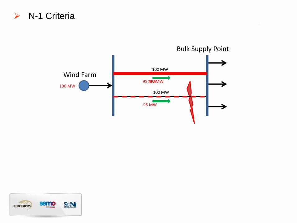
N-1 Criteria
Bulk Supply Point
190 MW
Wind Farm 100 MW
100 MW
95 MW
95 MW
190 MW

N-1 Criteria Limit steady-state (pre-fault) flows to prevent N-1 overloads Increased Constraints
Bulk Supply Point
100 MW 190 MW
Wind Farm 100 MW
100 MW
50 MW
50 MW

Simplest SPS Allow increased pre-fault flows on the assumption that automatic control action will Prevent an overload
Bulk Supply Point
190 MW
Wind Farm 100 MW
100 MW
95 MW
95 MW
190 MW 0 MW

SPS Policy
The EirGrid SPS policy is intended to balance the benefits of the scheme against the impact the scheme will have on:
– Other system users;
– The dispatch of other plant on the system;
– The additional overhead of maintaining such schemes;
– Increased complexity of operating the power system;
– Impact on system security
The SPS policy gives guidelines on how the scheme could be implemented and covers: – Operation;
– Redundancy;
– Maintenance;
– Failure;
– Communications;
– Control;
– Modelling and
– SPS Approval Process

SPS Example
During intact network, in theory, the 400 MW could be accommodated (assuming some power consumed by local loads and flows are relatively balanced)
[187 x 2 = 374] > [400 – loads]
187 MVA
187 MVA
15 MW
200 MW
70 MW
80 MW 35 MW

SPS Example
Local Generation would not be dispatched to 385 MW due to risk of N-1 overloads
Output from area would be limited to less than 200 MW
187 MVA
187 MVA
Wind
15 MW
200 MW
70 MW
80 MW 35 MW

SPS Example
A Special Protection Scheme could allow generation be dispatched beyond 200 MW by: – Monitoring the flows on the circuits
– Trip/Reduce generation output in the event of an overload
– Thus increasing the MW export from the area by eliminating risk of N-1 overloads
– EirGrid SPS Policy used to inform possible SPS options
– Range of options considered
– Most schemes require extensive communications and wind farm interactions
187 MVA
187 MVA
Wind
15 MW
200 MW
70 MW
80 MW 35 MW

SPS Example
Integrated Option: – Largest WF was selected as the most feasible location for the SPS
– All communications and actions could be incorporated within the same station
– Overload Relays would monitor flows on the Bally circuits
– In the event that overload was detected the 200 MW WF is tripped
– This scheme is Simple, Reliable, Fast and trips a single block of generation
187 MVA
187 MVA
Wind
15 MW
200 MW
70 MW
80 MW 35 MW

SPS Example
Integrated Option: – Works for trips at both ends
187 MVA
187 MVA
Wind 200 MW
70 MW
80 MW 35 MW

SPS Example
– Estimated 15 seconds between circuit trip and wind farm trip
– Circuits would not be damaged within this time
– Power flow needs to remain stable for 15 second period while max power flows
– Significant Power Flow issues with the extreme power shifts associated with the SPS scheme
– Angle difference and Vars absorbed by such large flows make the Power Flow scenario physically impossible
187 MVA
187 MVA
Wind 200 MW
70 MW
80 MW 35 MW
Summary of SPS Principles
SPS can be viable for local constraint issues Scheme should be binary Different schemes should not interact Schemes should not require Control Centre action post operation Schemes requiring 4-5 actions and tripping large amounts of generation are not ideal Level of generation tripped could be close to the largest infeed
Needs to be considered in terms of technical impact on the power system
SPS should not impact system security
