johnson controls automotive experience global supplier ... · the design will be made in 3d design...
TRANSCRIPT

Johnson Controls Automotive Experience Global Supplier Standards Manual
Design & Execution Requirements for Production Weld Fixture (Metals) December 2015
Uncontrolled if printed JCI GSSM Weld Fixture (Metals) December 2015 Page 1 of 53
1 Purpose
High production standard fixtures have to be designed and fabricated for applications where a high up-time is required because of high production requirements with a MU at 80% or higher. This fixture standard enables JCI to have a higher output, more flexibility, higher MU (Machine Utilization) and CU (Capacity Utilization). This document is for suppliers the mandatory guide line for design and execution of welding fixture.
2 Scope
This Fixture Design Requirement applies global within the Metals and Mechanisms manufacturing locations of Johnson Controls.
3 Responsibility
The Advanced Manufacturing Engineer (AME) and Plant Manufacturing Engineer (ME) are responsible for ensuring that all workstations are initially set-up and meet the required standards for welding fixtures.
The Integrator is responsible for all fixtures, related to the project. Integrator to provide labor to support the debug, runoff, and install at JCI/facility.
The plant Manufacturing Engineer (ME), Quality Engineer (QE), HSE Manager and Plant Maintenance Manager are responsible for approving the fixture and the final set-up of the GMAW, Spot and Laser workstation.

Johnson Controls Automotive Experience Global Supplier Standards Manual
Design & Execution Requirements for Production Weld Fixture (Metals) December 2015
Uncontrolled if printed JCI GSSM Weld Fixture (Metals) December 2015 Page 2 of 53
Table of Content
4 Additional Valid Documents ............................................................................................ 4
5 General documents ........................................................................................................ 4
6 Tooling Standard ............................................................................................................ 5
7 Welding feasibility study.................................................................................................. 6
8 Fixture documentation / design ....................................................................................... 6
9 General pneumatics ........................................................................................................ 7
10 Clamping concept ........................................................................................................... 9
11 Material rules ................................................................................................................ 17
12 Mechanical standards ................................................................................................... 18
13 Ergonomics................................................................................................................... 23
14 Fixture loading / unload strategy ................................................................................... 23
15 Poka yoke ..................................................................................................................... 24
16 Torch position – Torch angle ........................................................................................ 25
17 Fixture calibration ......................................................................................................... 25
18 Measure spikes user frame fixture ................................................................................ 25
19 Part presence - sensor controlled ................................................................................. 26
20 Fixture Visualization ...................................................................................................... 26
21 Quick Change Over ...................................................................................................... 27
22 Electric cable, sensors, etc ........................................................................................... 36
23 Special feature Laser welding fixture ............................................................................ 41
24 Connection fixture reused welding cell .......................................................................... 47
25 Examples GMAW fixture solutions ................................................................................ 48
Johnson Controls Automotive Experience Global Supplier Standards Manual
Design & Execution Requirements for Production Weld Fixture (Metals) December 2015
Uncontrolled if printed JCI GSSM Weld Fixture (Metals) December 2015 Page 3 of 53
Change Log
Date of Change Section Description of Change
December 2015 New Release

Johnson Controls Automotive Experience Global Supplier Standards Manual
Design & Execution Requirements for Production Weld Fixture (Metals) December 2015
Uncontrolled if printed JCI GSSM Weld Fixture (Metals) December 2015 Page 4 of 53
4 Additional Valid Documents
Additional to the specification following JCI-documents are mandatory for the supplier:
Mandatory documents:
Europe (EU): Technical Order Conditions, V1.3, 20150701
North America (NA): SESS, 4.4 / SEGS, 8.4
5 General documents
All Regions: Hazard Recognition Tool for Ergonomics (HRT4Ergo)
Are other and/or additional customer specifications mandatory, these customer documents have top priority.

Johnson Controls Automotive Experience Global Supplier Standards Manual
Design & Execution Requirements for Production Weld Fixture (Metals) December 2015
Uncontrolled if printed JCI GSSM Weld Fixture (Metals) December 2015 Page 5 of 53
6 Tooling Standard
General Requirements
Any deviation from this specification must be submitted to the Project-JCI/AME in writing prior to
a PO being used.
All fixture concepts must be approved in writing by JCI before start of the fabrication process.
Note1: Design meetings shall include a 3D CAD review of the GMAW Torch or the Spot weld Gun and verify that all welds can be reached and have the proper torch/gun access for the process.
Example GMAW: GMAW Torch Angles must have torch clearance, for all arc welds, within 45 degrees
+/-10 Degrees-Work Angle to the weld root and +/-10 degree-Travel Angle. See section 0 for more
details.
Example Spot: Spot guns have tips perpendicular to each other with 1,5mm shanks and flat tips.
Note2: Torch Access shall be reviewed from the point of view of Robot Technician’s ability to see where he is pointing the GMAW Torch. The Robot Technician must be able to see through and around the fixture details and fixture structure, to program the Robot for each individual weld.
Note3: All GMAW Welds are to be performed with weld joints positioned with +/- 15 degrees from horizontal. Tooling and positioner capability must be taken into account during the 3D CAD review with GMAW Torch.
Design approval does not relieve supplier from providing a fully functional tool capable of
produce an acceptable part conform to drawing specifications.
Tooling adjustments and modifications are in the responsibility of the tooling supplier during
install, debug and runoff.
All fixtures are to be measured on a CMM/Faro Arm and the report is part of the approval
process.
Part of the Approval Process--Integrator to present CMM/Faro Arm data to the AME for review
and written approval before welding on the fixture can begin.
Scheduled meetings and reports must be part of the project time-line to keep communication
open between JCI and Tooling Supplier.
Tooling has to be conform to load and size restrictions for the positioner chosen for the project.
Check with the plant manufacturing engineer for the type and manufacturer’s positioner
assigned to this project. During the quote or design phase of this project, the tooling supplier
must inform JCI if the tooling will exceed the positioner capability.
All component literature, on purchased items, must be supplied to JCI with in the time of fixture
acceptance.
Tooling designs must be reviewed during Tool Design Reviews, for access to shim the part
details and repair or replace details during maintenance. This includes access to clamp, sensor
and other items on the tool.
All Fixtures must have the Fixture ID and weight stamped on the front of the fixture.
Identification plate must be fixed with blind rivets on frame.

Johnson Controls Automotive Experience Global Supplier Standards Manual
Design & Execution Requirements for Production Weld Fixture (Metals) December 2015
Uncontrolled if printed JCI GSSM Weld Fixture (Metals) December 2015 Page 6 of 53
7 Welding feasibility study Fixture supplier is responsible for the analysis of weld access in 3D design. Fixture supplier has to deliver a welding feasibility study (simulation flow) with a robot welding simulation program, functions like “rob-cad” program. The o.k. simulation is content of design acceptance. JCI preferred offline welding programming to save time in the installation phase.
8 Fixture documentation / design
Documentation
1 set of documentation in 2 languages (English and local) will be delivered with fixtures
2x Paper
1x Data on CD or DVD
1x Operation manuals and maintenance manuals in English, and local language
3D Cad files Catia V5
Cad model in viewer format
CAD design / CAD file / design drawing
The design will be made in 3D design system (favoured Catia V5)
CAD 3D file format: Catia V5
All Cad models are given to JCI AME in viewer format (e-drawing, 3D-PDF, 3D-XML, etc.) include
structure tree from all design reviews.
All design files will be open files for revisions and changes.
2D CAD drawing in open files (CAD drawing) from single part will include dimensioning and
tolerances.
2D-drawing from modules and standard parts will include dimensioning and tolerances.
2D-drawing from pre-assemblies.
2D-drawing from assemblies.
All 2D drawings should be based on ISO Norms.
The supplier has to prepare a description for changing units.
Bill of material mechanic / pneumatic.
Pneumatic sequence diagram.
Measuring report 0 Basis.
Shim plan.
Electric documentation in E-Plan include.
Bill of material electric.
Maintenance guideline and spare part list has to be prepared.
Image of welding fixtures with sensor position and sensor number, when necessary several fixture
images.

Johnson Controls Automotive Experience Global Supplier Standards Manual
Design & Execution Requirements for Production Weld Fixture (Metals) December 2015
Uncontrolled if printed JCI GSSM Weld Fixture (Metals) December 2015 Page 7 of 53
9 General pneumatics
Observe the regional rules and different brands for NA, CN and EU
Flow controls for both open and closed function All manifolds have at least (1) unused station for the addition of a valve at later time Diodes are to be installed across the solenoids to prevent noise feedback All valve packs are to be shielded from spatter, use metal box System must be designed at the working pressure of 6bar / 85 PSI Operation with oil-free air is permissible All sensors must be equipped with LED status indicators
Pneumatic piping / pneumatic tubes For EU fixtures use plastic coated metal tube like Festo PM type for piping. For NA: Parker Model number 821FR-4-blk-rl and 821FR-6-blk-rl must be used as reference part numbers for the application For moving pneumatic hose use highly flexible single-sheath plastic tubing, flame retardant to UL 94 V0 … V2
Pneumatic fittings on piston, toggle clamps
All tube / pipe fittings with push in connectors Pneumatic air connection on all piston and toggle clamps mandatory made with standard flow control valve with QS quick push-in fitting, series D. All are exhaust air flow controlled
Use one way flow control valves, Swivel joint type, elbow outlet with slotted head screw. Example: Festo, types GRLA
Different brands see released component list Other tube / pipe connection are metal parts Example: Festo, type NPQM –D or NPQM-T
Different brands see released component list

Johnson Controls Automotive Experience Global Supplier Standards Manual
Design & Execution Requirements for Production Weld Fixture (Metals) December 2015
Uncontrolled if printed JCI GSSM Weld Fixture (Metals) December 2015 Page 8 of 53
Toggle joint clamp
i. Clamp with toggle joint mechanism and continuously adjustable opening angle
ii. Toggle locking mechanism
iii. Enclosed aluminum housing
iv. U-clamping arm
v. Continuously opening angle 45°-135° in depended of version
vi. Weld immune inductive sensing of closed and opened position
vii. All toggle clamps mandatory hand applied version
viii. Toggle clamps have to be locked in open position for easy unloading
ix. All pressure pieces on toggle clamps are shim adjusted
Different brands see released component list Minimum piston / cylinder diameter 40
Rotary clamps are not preferred!
Toggle clamps with heavy parts on arm use hydraulic damper system in open and close position to reduce the mechanical force on clamping arm
Johnson Controls Automotive Experience Global Supplier Standards Manual
Design & Execution Requirements for Production Weld Fixture (Metals) December 2015
Uncontrolled if printed JCI GSSM Weld Fixture (Metals) December 2015 Page 9 of 53
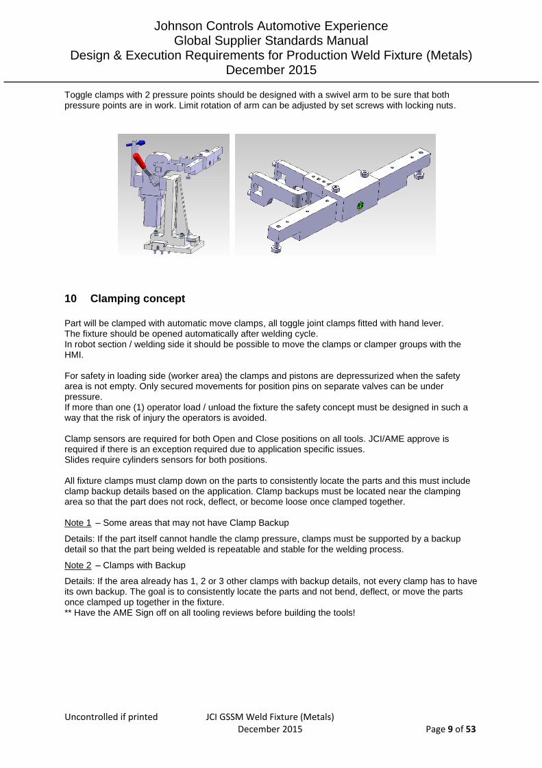
Toggle clamps with 2 pressure points should be designed with a swivel arm to be sure that both pressure points are in work. Limit rotation of arm can be adjusted by set screws with locking nuts.
10 Clamping concept
Part will be clamped with automatic move clamps, all toggle joint clamps fitted with hand lever. The fixture should be opened automatically after welding cycle. In robot section / welding side it should be possible to move the clamps or clamper groups with the HMI. For safety in loading side (worker area) the clamps and pistons are depressurized when the safety area is not empty. Only secured movements for position pins on separate valves can be under pressure. If more than one (1) operator load / unload the fixture the safety concept must be designed in such a way that the risk of injury the operators is avoided. Clamp sensors are required for both Open and Close positions on all tools. JCI/AME approve is required if there is an exception required due to application specific issues. Slides require cylinders sensors for both positions. All fixture clamps must clamp down on the parts to consistently locate the parts and this must include clamp backup details based on the application. Clamp backups must be located near the clamping area so that the part does not rock, deflect, or become loose once clamped together. Note 1 – Some areas that may not have Clamp Backup
Details: If the part itself cannot handle the clamp pressure, clamps must be supported by a backup detail so that the part being welded is repeatable and stable for the welding process.
Note 2 – Clamps with Backup
Details: If the area already has 1, 2 or 3 other clamps with backup details, not every clamp has to have its own backup. The goal is to consistently locate the parts and not bend, deflect, or move the parts once clamped up together in the fixture. ** Have the AME Sign off on all tooling reviews before building the tools!
Johnson Controls Automotive Experience Global Supplier Standards Manual
Design & Execution Requirements for Production Weld Fixture (Metals) December 2015
Uncontrolled if printed JCI GSSM Weld Fixture (Metals) December 2015 Page 10 of 53
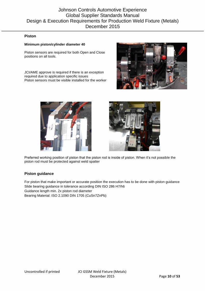
Piston
Minimum piston/cylinder diameter 40 Piston sensors are required for both Open and Close positions on all tools.
JCI/AME approve is required if there is an exception required due to application specific issues Piston sensors must be visible installed for the worker
Preferred working position of piston that the piston rod is inside of piston. When it’s not possible the piston rod must be protected against weld spatter
Piston guidance
For piston that make important or accurate position the execution has to be done with piston guidance
Slide bearing guidance in tolerance according DIN ISO 286 H7/h6
Guidance length min. 2x piston rod diameter
Bearing Material: ISO 2.1090 DIN 1705 (CuSn7ZnPb)

Johnson Controls Automotive Experience Global Supplier Standards Manual
Design & Execution Requirements for Production Weld Fixture (Metals) December 2015
Uncontrolled if printed JCI GSSM Weld Fixture (Metals) December 2015 Page 11 of 53
Special Piston solution Example: Festo DFM Piston with adjustable end stop outside solution Different brands see released component list
Example: Festo DFM Piston with end stop, hand actuated
Different brands see released component list
Example: Festo Piston ADVU-40-15-P-A-S2, hand actuated with guidance
Different brands see released component list

Johnson Controls Automotive Experience Global Supplier Standards Manual
Design & Execution Requirements for Production Weld Fixture (Metals) December 2015
Uncontrolled if printed JCI GSSM Weld Fixture (Metals) December 2015 Page 12 of 53
Guidance and guidance rails If slides or rails are used to move/shuttle fixture details, ground path must not be through the bearings and must have ground straps around the slide system. If slides or rails are used to move/shuttle fixture details, spatter/dirt guards must be part of the design, by the tooling supplier, so the bearings and end stops are kept clean. The cover will be easy to dismantle designed.
All slides must be shot pinned for final position verification.
All slides must have bore diameters at least 8 mm or greater. The goal is to make sure the slide has a
greater force than clamps or other details that might be pushing against it. All Guidance / guide rails have a fixed hardened, adjustable end stop in both slide directions.
Use minimum two parallel working slides with min. three guiding wagon per slide unit.
The guide rail system has to be designed with master rail (longer rail) and slave rail (shorter rail).
Guide wagons have to be fixed with hardened pins on the parts.
Guidance / guide rails that make important positions have to be locked in working position with a
piston, example see picture below.
Spring loaded pressure pieces When necessary use spring loaded pressure pieces size M8 Ganter or Drabber
Different brands see released componen
Shim block systems / part placement
Shim block systems for position pins
All fixture details must have 5mm shims to make the position of the detail at the nominal part location in the X, Y and Z directions. (Fixture must have shimming capabilities in X, Y, and Z).

Johnson Controls Automotive Experience Global Supplier Standards Manual
Design & Execution Requirements for Production Weld Fixture (Metals) December 2015
Uncontrolled if printed JCI GSSM Weld Fixture (Metals) December 2015 Page 13 of 53
Examples:
Shim block system for Z surface position All part surface blocks must be shimable in z according to drawing or according to function.
Examples:
Shim block system for tube position
Different solution for tube positioning possible solution.
Position for tube position in V-block, shim in Z, for X adjustment separate plate needed possible.

Johnson Controls Automotive Experience Global Supplier Standards Manual
Design & Execution Requirements for Production Weld Fixture (Metals) December 2015
Uncontrolled if printed JCI GSSM Weld Fixture (Metals) December 2015 Page 14 of 53
Position for tube position in V-block, shim in Z and X possible.
Position for tube position in shim block, shim in Z and X possible.
Shim package in zero CAD design position
o JCI standard base block: 5 mm in package 0,1mm, 0,25mm, 0,5mm, 1mm. o Surface blocks: 5 mm in package 0,1mm 0,25mm, 0,5mm, 1mm o Other positioning parts: 5 mm in package 0,1mm, 0,25mm, 0,5mm, 1mm.
Shim design
o All shim plates have to be burr free o At least required available thickness: 0,1mm 0,2mm 0,3mm 0,5mm 1,0mm 2,0mm 3,0mm
5,0mm o NA: 0,1mm and 0,2mm no valid, NA: use 0,25mm as smallest size
Johnson Controls Automotive Experience Global Supplier Standards Manual
Design & Execution Requirements for Production Weld Fixture (Metals) December 2015
Uncontrolled if printed JCI GSSM Weld Fixture (Metals) December 2015 Page 15 of 53
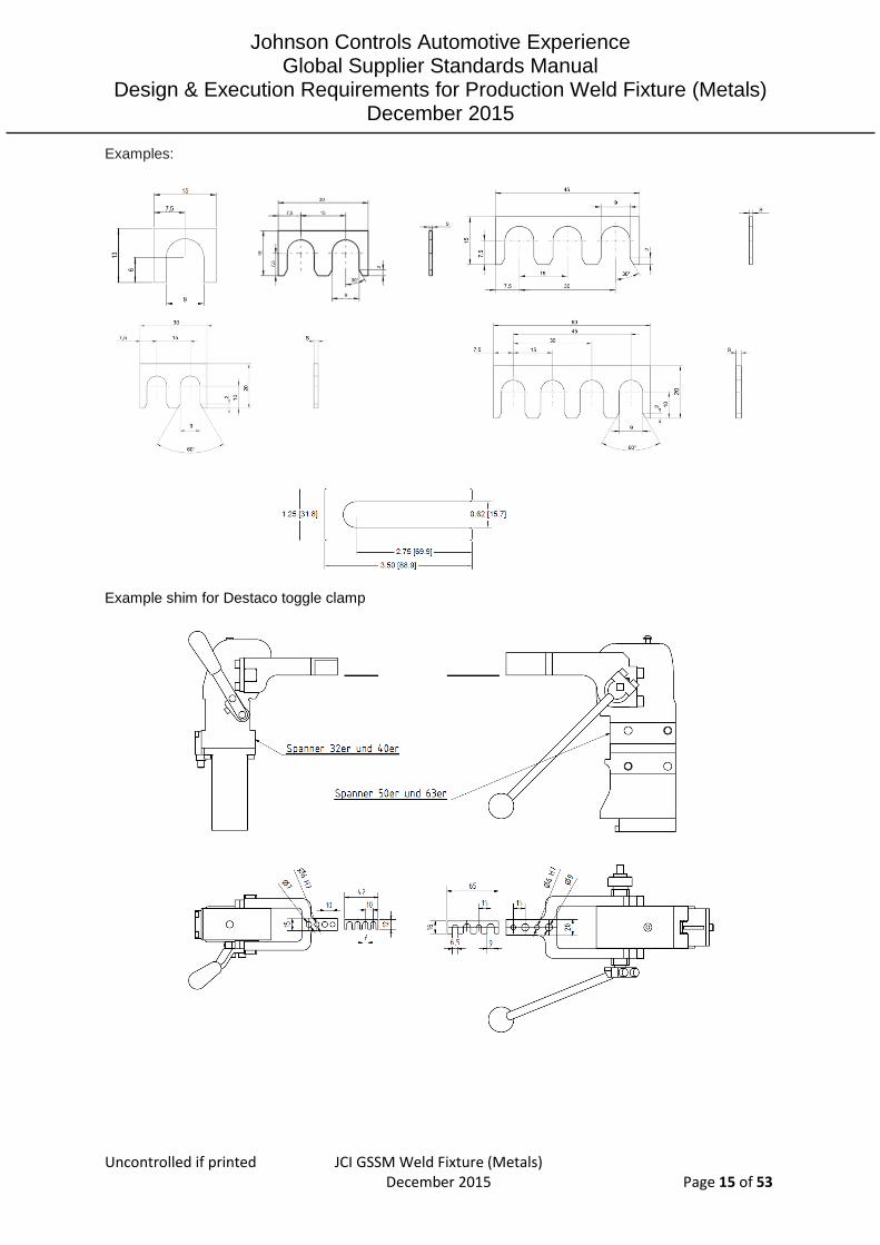
Examples:
Example shim for Destaco toggle clamp

Johnson Controls Automotive Experience Global Supplier Standards Manual
Design & Execution Requirements for Production Weld Fixture (Metals) December 2015
Uncontrolled if printed JCI GSSM Weld Fixture (Metals) December 2015 Page 16 of 53
Flat washer / shim ring
o All washers have to be burr free o At least required available thickness: 0,1mm 0,2mm 0,3mm 0,5mm 1,0mm 2,0mm 3,0mm
5,0mm. o NA: 0,1mm and 0,2mm no valid, NA: use 0,25mm as smallest size
o With each fixture the supplier has to deliver a set of shims and a set of washers / shim rings in separate boxes, see figure below.
o Minimum quantity of each shim: o 15 pcs per used size 0.1mm up to 1mm o 5 pcs per used size 2mm up to 5mm o Minimum quantity of each shim ring: 10 pcs per size 0.1mm up to 1mm
In North America Douglas Stamping Company Shim’s must be utilized:
When tooling supplier has completed with fixture installation and pre- acceptance, a shim map must be provided before approval by JCI.

Johnson Controls Automotive Experience Global Supplier Standards Manual
Design & Execution Requirements for Production Weld Fixture (Metals) December 2015
Uncontrolled if printed JCI GSSM Weld Fixture (Metals) December 2015 Page 17 of 53
11 Material rules
Part surface / material
All fixture details, which are used to hold parts in place, that have a weld that is 30mm or closer to the fixture, details must be Ampco 21®, Elkonite® or Elmedur X®. Also any details that hold a part, which has a weld located on top of the fixture Detail, must also be Ampco 21®, Elkonite® or Elmedur X®. All fixture details which come in contact with component parts, must be hardened to 52 RC minimum. Ampco®, Elkonite® or Elmedur® details are required in high weld spatter areas. A2 tool steel is required for hardened details. All Fixture-Clamp details that are 30mm or closer to the weld joint must be Elkonite ® or Elmedur X ® details. JCI AME have to give approval for AMCO ® material to be used based on the specific application. Welding spatter sustained metal parts or pins have to be laminated /cladded; TIN (Titannitrid), decide in design meetings which area will be sustained. Using normal copper materials is forbidden for positioning parts. All fixtures parts have to be protected against corrosion with painting, black oxide finish or galvanizing. Reference elements surface roughness will be Material information: Ampco 21® (Aluminium - Bronze alloy): www.ampcometal.com Ampcoloy 940 welding electrodes material, EU use current Ampco 21
Elkonite ® (Tungsten- Copper alloy): www.tuffaloy.com
Elmedur X ® (Copper alloy - CuCr1Zr - A 2/2): www.thyssenduro.com
Cover / welding spatter protection
The fixture design must include protection guards against weld spatter. Weld fixtures that include weld parts with spatter free zones must have spatter guards that completely cover and protect the spatter free zone during welding as called out on the part drawing. More or different areas can be defined from AME out of his experience in design phase without any extra charge. For part applications with no spatter zones on part areas, weld nuts, holes, or other features, guards must be made of appropriate materials. Class 3 Copper, Ampco 21® Aluminum Bronze, Elkonite ® or Elmedur X® must be used and tooling supplier must have approval from JCI before fabrication starts. Any cover or detail, to protect the spatter free areas of the part, that is 50mm or closer to the Weld Joint must use Ampco 21®, Elkonite ® or Elmedur X ® material for spatter guards. All downstream GMAW weld fixtures, which have parts with spatter free zones, must also have spatter guards to completely cover and protect the spatter free zone, of that individual part or parts, during the next welding steps to complete a final assembly. The weld spatter protections must have a minimum thickness of 2.5 mm. Cover material: copper sheet or brass sheet. For special applications it is possible to choose silicone. The fixture must be designed that weld spatters and dirt doesn't accumulate (openings, guide plates). Weld protection must be compact and robust and ensure protection of linear rails, cylinder rods etc. Covers must be independent from clamping points and be adjustable.
R 6,3

Johnson Controls Automotive Experience Global Supplier Standards Manual
Design & Execution Requirements for Production Weld Fixture (Metals) December 2015
Uncontrolled if printed JCI GSSM Weld Fixture (Metals) December 2015 Page 18 of 53
Burn through protection for welding of thin material
For welding of thin material thickness 1.0mm and below the execution is to be made with burn through protection. Burn through protection parts / back up blocks have to be made out of Material Ampco 21 ® or ceramic.
12 Mechanical standards
Bolts / washer / thread / dowels
Use outer hexagon head bolts in priority, inner hexagon head bolts can be used only when it’s not possible to work with outer hexagon head bolts. In high spatter areas, Hex Head Bolts have to be used unless change has been signed off by product-responsible AME. (If Allen-Socket Headed Cap Screws are used, heat resistant clay must be inserted in to the bolt).
All bolts used to attach details to the frame must be M6 or greater. Anything less than this size is
unacceptable. No US bolts will be acceptable. Utilize only Metric standard. Hexagon head bolt
Hexagon head bolts of DIN EN ISO 4014 (DIN 931-1) see figure 6; or DIN EN ISO 4017 (DIN
933) see figure 7.
All Hex head bolts zinc patted.
Preferred dimension M6, M8, M10, M12.
All bolts must be easy reachable for assembling and disassembling
Figure 6
Figure 7

Johnson Controls Automotive Experience Global Supplier Standards Manual
Design & Execution Requirements for Production Weld Fixture (Metals) December 2015
Uncontrolled if printed JCI GSSM Weld Fixture (Metals) December 2015 Page 19 of 53
Allen-Socket Headed Cap Screws (inner hexagon head bolts) Not to use in high risk weld spatter area!
o Socket head bolts of DIN EN ISO 4762 (DIN 912) see figure 7. o All Hex head bolts zinc patted. o Preferred dimension M6, M8, M10, M12. o All bolts must be easy reachable for assembling and disassembling.
Figure 7
Set screws
According to function use following set screw types:
Inner Hexagon socket set screws with flat tip DIN EU ISO 4026 (DIN 913) Preferred dimension M6, M8, M10.
Example for use when: Fixation of position pins
Inner Hexagon pressure screws with radius half-dog point.
The pressure screws with nipple are used when a point pressure or support point are required. Screw quality class / Screw grade 10.9. Pin, hardened tool steel. Preferred dimension M6, M8, M10.

Johnson Controls Automotive Experience Global Supplier Standards Manual
Design & Execution Requirements for Production Weld Fixture (Metals) December 2015
Uncontrolled if printed JCI GSSM Weld Fixture (Metals) December 2015 Page 20 of 53
Example for use when: Fine adjustments are required
Bolt lock
For bolts that are used in important areas the bolt fixing has to be secure bolts with liquid bolt lock. Temperature resistant from -55 °C to +150 °C. Preferred use LOCTITE screw lock mid-strength.
Washer / spring washer
For all screws use washer. Washer zinc patted. Medium washer DIN EN ISO 7090 (DIN125 type B).
To secure screws use spring lock washer DIN 128 type A.

Johnson Controls Automotive Experience Global Supplier Standards Manual
Design & Execution Requirements for Production Weld Fixture (Metals) December 2015
Uncontrolled if printed JCI GSSM Weld Fixture (Metals) December 2015 Page 21 of 53
Thread insert in weak soft and weak materials
Threaded inserts must be used for all tapped holes into aluminum or other soft / weak materials to create a high strength fastening. Keenserts ® or Ensat ® are preferred. Tooling supplier must have written approve for a deviation.
Preferred insert type: Keenserts ® by Alcoa
Further information: www.alcoa.com Worldwide available
Preferred insert type: Ensat ® S302 by Kerbkonus
Further information: www.kerbkonus.de Worldwide available
Alternative, but not preferred insert type: Helicoil ® plus by Böllhoff
Further information: www.boellhoff.de Worldwide available
Cylindrical pins / dowel
All tooling component part locators, mounted clamps, mounted slides, and other devices must use a minimum of two dowels per unit for location.
In prior dowel holes must have a through hole for easy removal of dowel.
Mounting dowels must have a minimum of 1.5 X diameter engagement into the adjacent detail/member/tool plate at the maximum shimmed condition. In first prior use through holes for dowel
o Cylindrical pins DIN EN ISO 8734 (DIN 6325) o Tolerance class m6 o Hardened: hardness 550 – 650 HV 30 ; 60+/-2 HRC, dressed to size and lapped o Preferred diameter Ø 6mm, Ø8mm and Ø10mm

Johnson Controls Automotive Experience Global Supplier Standards Manual
Design & Execution Requirements for Production Weld Fixture (Metals) December 2015
Uncontrolled if printed JCI GSSM Weld Fixture (Metals) December 2015 Page 22 of 53
When no through holes possible, use cylindrical pins with inner thread
o Cylindrical pins with internal thread DIN EN ISO 8733 (DIN 7979) o Tolerance class m6 o Hardened: hardness 550 – 650 HV 30 ; 60+/-2 HRC, dressed to size and lapped o Preferred diameter Ø 6mm, Ø8mm and Ø10mm o For disassembling the tread must be easy reachable
Position pin concept / part connection blocks
Part Ejectors have to be installed to assist the operator unload the parts. This must be used where necessary on large to medium parts. Small parts must come out easily or ejectors must be installed. All position pins and part connection blocks must interchangeable designed. Position pins must stay in load direction of welding group. If the part is pinned, and this caused unload issues in order of part geometry or heat distortion risk, the pins must be designed for retracting / automatic removal instead of part ejectors. Consider safety rule by automatic pin moving. When the single part positions are made with two pins in holes with distance more than 50mm, min. one both the position pins will be adjustable designed with shim in XY direction.
Details Position pins
In all fixtures use follow pin design, special pins could be used when it’s not possible to use the standard pins. Position pin material 50CrMoV13 surface hardened 52 RC hardened minimum deepness 0,5mm. All position pins have to be locked with screws. Welding spatter sustained metal parts or pins will be laminated with TIN (Titannitrid). Location pins must be accessible for replacement with minimal effort in disassembly. In General, Pin Diameter have to be based on Print Hole Nominal Size (PHN) – the hole tolerance (PHT) on the print–0,05mm (0.02 inches) Tooling Pin Design has to be based on the material part thickness and the bullet nose taper of the pin. See picture below. All two-way location pins must be fabricated to prevent rotation in the mounting block. Any pin that has an orientation feature, two way pins, diamond shape pins, and other types, must have a flat built on one side of the pin. Any design deviations must be approved by the AME if there is a new concept for pin orientation. Pin length is required on part material thickness: Straight length of pin = Material thickness + 1.5mm Angle of spike 60 degree, min. 4mm length. Proportion for pin guidance to pin diameter must be design according technical rules.
Pin version with set screw clamping

Johnson Controls Automotive Experience Global Supplier Standards Manual
Design & Execution Requirements for Production Weld Fixture (Metals) December 2015
Uncontrolled if printed JCI GSSM Weld Fixture (Metals) December 2015 Page 23 of 53
Pin version with outer thread or inner thread. All Part pins are to be tapped for M8 or M10 bolt / nut. Part detail will have through-hole in detail for pin bolt to mount to the part/fixture detail.
13 Ergonomics
Detailed information: JCI Hazard Recognition Tool for Ergonomics (HRT4Ergo)
In fixture design consider mandatory that red areas of ergonomic sheet below are not usable for part location.
14 Fixture loading / unload strategy
Fixtures design in first strategy to easy load the single parts and easy unload the welding group. Consider items below in design.
Fixture-design with auto-eject function / nest free for loading. Description: Welded part will lift out of the fixture for example with a gripper system, after the fixture is open in loading area (worker side), then the fixture is ready for single part loading. Fixture design with stable pre-position items to help the worker with single parts easy and fast loading process.
In priority the fixture will be designed to clamp single parts in automatic process, but all toggle clamps applied with hand lever to allow the worker to close the toggle clamp by hand. This helps the worker by loading of complex or strong parts. Complicate or very small single part mandatory to clamp from worker by hand to secure a clamping problem.
If necessary the fixture will lift out of position pins or position pins will remove. Use pre-positioning stoppers for easy loading. The fixture weight will balance according to the force of turning axes of welding cell.

Johnson Controls Automotive Experience Global Supplier Standards Manual
Design & Execution Requirements for Production Weld Fixture (Metals) December 2015
Uncontrolled if printed JCI GSSM Weld Fixture (Metals) December 2015 Page 24 of 53
15 Poka yoke
First priority the fixture will be designed according to a Poka-Yoke system with mechanical solution.
1. mechanical protection against anti rotation
2. mechanical protection against incorrect position
3. mechanical protection against insert incorrect part
In case that mechanical Poka-Yoke is not possible, the Poka-Yoke solution must be designed with electric sensors solution. 4. Part identification (same part in different nests or fixtures) must be provided. If it is not cycle time
relevant, welding spots are preferred. For example; Nest 1 = spot in left corner, Nest 2 = spot in right corner. If a welding spot increase the cycle time in that way that customer tact will not be reached, also a punch mark (integrated in the clamping) is possible.
wrong position

Johnson Controls Automotive Experience Global Supplier Standards Manual
Design & Execution Requirements for Production Weld Fixture (Metals) December 2015
Uncontrolled if printed JCI GSSM Weld Fixture (Metals) December 2015 Page 25 of 53
16 Torch position – Torch angle
Access to welding seam and welding torch angle. see figure 1 Clearance for welding torch: minimum effective welding seam length (shown in CAD model) + 5mm lead in/out + 5mm welding seam tolerance (summary + 10mm) Weld torch access must have a 5mm clearance from any fixture point Welding torch 22° (goose neck) GMAW Torch Angles must have torch clearance, for all arc welds, within 45 degrees +/- 10 Degrees-Work Angle to the weld root and +/- 10 degree-Travel Angle, Forward Angle 0 Degrees
Figure 1
17 Fixture calibration
All fixtures are to be measured and adjusted in zero design position, maximum deviation to design 0 position +/- 0,05mm. Each fixture must have 3 CMM measuring balls or holes with covers as part of the fixture design. The measuring points x, y, z coordinates have to be labelled, Label firm fixed with blind rivet on frame. Easy access for measuring tool should be considered. Protect this area in production against welding spatters. If there are separate Plates for each tool within a frame, then each tooling plate must have the CMM balls / holes for measuring the tool. On a frame the tooling plates will be mounted to it, so more than one tooling plate can be placed in front of a robot. Test report include delivery report is part of the approval process. Measuring drawing include. All screws after first calibration are marked with colour to make visible that the screws are fixed.
Shim log in basic of first assembling / first calibration is content in documentation There must be also a changing unit description, (part-matrix, version-matrix, unit location and how to change the units).
18 Measure spikes user frame fixture
To define the user frame measure spikes on fixture needed. Three tooling points on top of the fixture are required. The three points have to be mounted on the fixture so that each robot can reach all three points. If necessary, each robot may require their own set of points on the fixture (top and bottom side) depending on the reach of the robot and tooling access. The spikes have to have a protect-cover.
or The user frame must be defined before starting the robot welding programming.

Johnson Controls Automotive Experience Global Supplier Standards Manual
Design & Execution Requirements for Production Weld Fixture (Metals) December 2015
Uncontrolled if printed JCI GSSM Weld Fixture (Metals) December 2015 Page 26 of 53
19 Part presence - sensor controlled
Part present sensors are required for each and every part loaded into each fixture. Integrator must assume that it is also required for Weld Nuts as well, even if they are not welded in the fixture but are expected to come as part of the assembly. In case the pre-welded- group will proceed in the welding process, the presence of this group can be made with one present sensor. In case that a pre-welding group is produced in this fixture and will proceed into a next welding step, the presence of this group can be made with one present sensor. Check with JCI/AME for the expected parts there is a Poke-Yoke in place for each tool during the quote phase.
In General, Part Present sensors have to be engineered to reduce downtime. Tooling
Supplier/Integrator is responsible for placing the part sensor location in the area where it will be most likely to have no sensor failure due to spatter or heat damaging to the sensor face, side and cable.
20 Fixture Visualization
Johnson Controls Automotive Experience Global Supplier Standards Manual
Design & Execution Requirements for Production Weld Fixture (Metals) December 2015
Uncontrolled if printed JCI GSSM Weld Fixture (Metals) December 2015 Page 27 of 53
21 Quick Change Over
Welding cell / fixture connection for JCI standard welding cells, Connection table / fixture with pins to define a repeatable fixture position. For electric and pneumatic connection of exchange units use metal plugs and metal sockets Supplier: Harting
Type for electric and pneumatic connection:
HAN-modular, twin system electric and pneumatic in one plug system
Quick Change Over Procedure
1. Quick Change Over in process
2. Bring fixture in change position (worker side)
3. Pull Plug contact (air, electric)
4. Bring change device with forklift to fixture and connect
5. Open screw-connection from fixture to quick change ridge
6. Take off fixture
7. Bring fixture to the allocated space
8. In the meantime change the part allocation
9. Pick up new fixture with change device and bring it to the cell into the change position
10. Put fixture on locating pin and displace fixture
11. Close screw-connection from fixture to quick change ridge. Bring change device out
12. Connect Plug contact (air, electric)
13. Choose new fixture program
14. Load fixture and start welding
15. After the first part is welded supervisor has to make a visible check of the part. Is the
result n.o.k. the robot has to be re-teached and the welding starts again.
After visual o.k. check from first part supervisor has to bring part to the cut &etch
16. The production starts right away after the visual o.k. check. Produced parts cannot be
shipped to the customer until the cut & etch check is o.k.
17. If the cut & etch check is n.o.k., robot has to be re-teached, produced parts have to
be re-worked. After o.k. cut & etch, produced parts are released
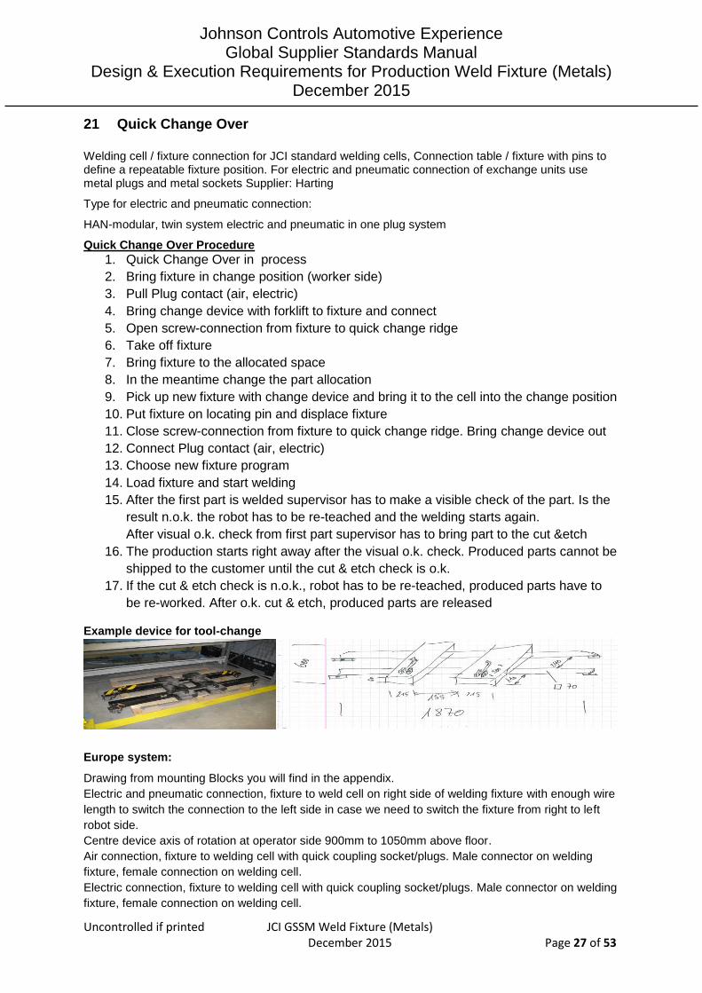
Example device for tool-change
Europe system:
Drawing from mounting Blocks you will find in the appendix.
Electric and pneumatic connection, fixture to weld cell on right side of welding fixture with enough wire
length to switch the connection to the left side in case we need to switch the fixture from right to left
robot side.
Centre device axis of rotation at operator side 900mm to 1050mm above floor.
Air connection, fixture to welding cell with quick coupling socket/plugs. Male connector on welding
fixture, female connection on welding cell.
Electric connection, fixture to welding cell with quick coupling socket/plugs. Male connector on welding
fixture, female connection on welding cell.

Johnson Controls Automotive Experience Global Supplier Standards Manual
Design & Execution Requirements for Production Weld Fixture (Metals) December 2015
Uncontrolled if printed JCI GSSM Weld Fixture (Metals) December 2015 Page 28 of 53
Mechanical

Johnson Controls Automotive Experience Global Supplier Standards Manual
Design & Execution Requirements for Production Weld Fixture (Metals) December 2015
Uncontrolled if printed JCI GSSM Weld Fixture (Metals) December 2015 Page 29 of 53
Cell fixture dimensions Basic Arc Cell / Basic Spot Cell
Compact Arc Cell

Johnson Controls Automotive Experience Global Supplier Standards Manual
Design & Execution Requirements for Production Weld Fixture (Metals) December 2015
Uncontrolled if printed JCI GSSM Weld Fixture (Metals) December 2015 Page 30 of 53
Compact Laser Cell

Johnson Controls Automotive Experience Global Supplier Standards Manual
Design & Execution Requirements for Production Weld Fixture (Metals) December 2015
Uncontrolled if printed JCI GSSM Weld Fixture (Metals) December 2015 Page 31 of 53
4-Station Laser Cell

Johnson Controls Automotive Experience Global Supplier Standards Manual
Design & Execution Requirements for Production Weld Fixture (Metals) December 2015
Uncontrolled if printed JCI GSSM Weld Fixture (Metals) December 2015 Page 32 of 53
Fixture Controls Main PLC Siemens S7 CPU S7-1516F-2PN/DP in Cell as master. Slaves on fixtures are standardized FESTO remote I/0-Systems CPX in combination with the valve terminals VTSA; communication interface Profinet (Ethernet).
Festo CPX + VTSA
CPX: Festo Remote I/O-System (Profinet) communicates with the main PLC Usable as: stand-alone unit; remote controller Ethernet; remote controller fieldbus; remote I/O-unit as slave
VTSA: Festo Valve Terminal Individual configurable – depending on the number of needed I/Os
Quick connect for electrical power and interface with HARTING Overview Jig Plug connectors –X1/-X2/-X3/-X4
Pneumatic quick-connect, Festo, type KS4 will be used as pneumatic connection between cell / fixture.

Johnson Controls Automotive Experience Global Supplier Standards Manual
Design & Execution Requirements for Production Weld Fixture (Metals) December 2015
Uncontrolled if printed JCI GSSM Weld Fixture (Metals) December 2015 Page 33 of 53
North America System:
Figure 3 — JCI Head Stock Mounting Plate -– Use this design unless a deviation is approved by JCI/AME for the program. (Note: Integrator to Machine Plates and mount them to the Fixtures).
Figure 4 — JCI’s Latest Design –- “Tool Retainer “at the Head and Tail Stock Positioner Plate (Note: Integrator to purchase Tool Retainers from Automated Systems, Inc. and mount them to the positioner Head/Tail Stock plates
Figure 3
Figure 4

Johnson Controls Automotive Experience Global Supplier Standards Manual
Design & Execution Requirements for Production Weld Fixture (Metals) December 2015
Uncontrolled if printed JCI GSSM Weld Fixture (Metals) December 2015 Page 34 of 53
Fixture Control Main PLC Allen Bradley Compact Logic Guard Logic 1768-L43S/L45S Control Logic Guard Logic 1756L63S/L65S1756-L7xS. All fixtures must be equipped with Allen Bradley Micro-logic 1200/1400/1500 processor with 14k user memory. The Micro-logic must be capable of communicating to a SLC 5/05 via an ENI module and Ethernet hub. The Micro-logic processor must also be capable of communicating with the Allen Bradley Control-logic platform.
Quick connect for electrical power and interface
Amphenol Male Amphenol Connector, 18 pin, 1/4 turn MS-3116-F14-18P Amphenol Female Amphenol Connector, 18 pin, 1/4 turn MS-3116-F14-18S Amphenol Flange Mount Male Amphenol, 18 pin, 1/4 turn MS-3112-E14-18P
Welding cell / fixture connection for re-used welding cells For detailed welding cell information and welding fixture connection of reused equipment ask the responsible project AME.
Fast change system for fixture exchange elements
For fixture exchange elements use fast change system with swash plates, hardened screw bolts and hardened position pins / hardened bush. Example below, Figure 5
Figure 5
Part Supplier: Norelem (www.norelem.com) Type: Swash plate Norelem order nr: 07520-08 according DIN 6371
Bolt Norelem order nr: 07530-06 Screws

Johnson Controls Automotive Experience Global Supplier Standards Manual
Design & Execution Requirements for Production Weld Fixture (Metals) December 2015
Uncontrolled if printed JCI GSSM Weld Fixture (Metals) December 2015 Page 35 of 53
Nut Norelem order nr: 07240-08
Bolt DIN 939- M8x55
Position of exchange units will be repeatable in using of hardened bushing according DIN172 / ISO 4247 and hardened pins, one round pin and one sword pin, see picture
Hardened Pin: diameter Ø 10mm, clearance m6
Hardened bushing according DIN172 Form B / ISO 4247: inner diameter Ø10mm, clearance F7
Position pins / bushing has to be protected against weld splatters For each exchange group use mechanical Poka Yoke, mandatory only one position over all
same fixtures can be possible to mount. All exchange groups variances have to be controlled
via welding cell PLC. Solution for detection has to be made with separate sensor.
All exchange groups have to be designed with 3D shim system to make sure that all parts
could have different adjustments.

Johnson Controls Automotive Experience Global Supplier Standards Manual
Design & Execution Requirements for Production Weld Fixture (Metals) December 2015
Uncontrolled if printed JCI GSSM Weld Fixture (Metals) December 2015 Page 36 of 53
22 Electric cable, sensors, etc
Observe the regional rules and different brands for NA, CN and EU
For reused equipment ask responsible AME for detailed information
Sensor types / proximity switches for part present detection Regarding to distance of welding area select the sensor type see table below
Distance to welding area more the 200mm Distance to welding area 20mm – 200mm Distance to welding area < 20mm
Remark: Steelface W51- ceramic coated sensor brand Balluff
Inductive sensor M8x1 preferred size
o With 2mm rated switching distance o Yellow LED for signal o M8x1 plug connection o 3 pin plug o IP 67 protection o Example Supplier: IFM / Sensor type:IE5338 o Example Supplier: Balluff / Sensor type: BES00CK o Close to welding area mandatory use ceramic coated
Different brands see released component list

Johnson Controls Automotive Experience Global Supplier Standards Manual
Design & Execution Requirements for Production Weld Fixture (Metals) December 2015
Uncontrolled if printed JCI GSSM Weld Fixture (Metals) December 2015 Page 37 of 53
Inductive sensor square 8x8
o With 2mm rated switching distance o Red LED for signal o M8x1 plug connection o 3 pin plug o IP 65 protection o Example Supplier: IFM / Sensor type:IL5004
Different brands see released component list
Not preferred but for special task usable, photoelectric or laser sensors, special protection needed.
AME release required.
For NA consider SESS and SEGS.
For EU consider Technical Order Conditions.
Sensors will be protected against welding spatters, use weld spatter protected shuck such as Balluff
brass sleeve to protect the thread to sensors.
Mandatory all sensors are to be labeled.
Sensor positions will be aligned considering accessibility and sensor light visibility. Sensors and initiator from cell and fixtures will be self-controlled, get back so PLC controlled zero signal after removing the welding parts. In fault situations the number of faulty sensor will be indicated at the welding cell HMI. In case of limited space to mount a part sensor on extra device, the sensor can be located directly in the block. Don’t use thread for fixing when a Sensor is direct mounted in a fixture part or fixture block.

Johnson Controls Automotive Experience Global Supplier Standards Manual
Design & Execution Requirements for Production Weld Fixture (Metals) December 2015
Uncontrolled if printed JCI GSSM Weld Fixture (Metals) December 2015 Page 38 of 53
Example for good solution sensor-switch fixation / mounting:
Clamp sensors in brass tube (open slit) with set screw, very easy to set the sensor in right position.
Example for indirect part control of small parts / close to weld seam Close to welding seam use Fixing stop cross applicable. Fixed stop combined with corresponding mounting cuff. Switching point between the sensor switch and trigger pin can be set wherever needed.
Balluff BES 08-FA-49 order code BAM009L
Size M8x1
Stainless steel
Spring force 3N
Spring deflection 2mm
Use Balluff BES 08-FA-BS-8,0-W order code BAM009T. With this part the switching point between the proximity switch and trigger pin can be set wherever needed.
mounting view with BAM009T view without BAM009T
Part sensors located in welding spatter free areas or areas where the risk of spatters is low
Johnson Controls Automotive Experience Global Supplier Standards Manual
Design & Execution Requirements for Production Weld Fixture (Metals) December 2015
Uncontrolled if printed JCI GSSM Weld Fixture (Metals) December 2015 Page 39 of 53

Johnson Controls Automotive Experience Global Supplier Standards Manual
Design & Execution Requirements for Production Weld Fixture (Metals) December 2015
Uncontrolled if printed JCI GSSM Weld Fixture (Metals) December 2015 Page 40 of 53
Sensor cabling Cabling has to be done properly not to disturb shim and mechanical adjustments. (cable installation should be in / under base frame in cable trays etc.). Connectors sensor side, M8 female, 3-pin, no LED and right angle preferred Sensor cables on moving parts need a cable relief. Mandatory all sensor cables are welding spatter protected with metal / silicon fibre protected hose. Sensor cables will be protected against mechanical damage. Mandatory all sensors supply with 300mm cables. M8x1 connection / plugs for easy maintenance, direct installation / connection in electric cabinet not allowed. Cable example: supplier Balluff / type: BCC0CAN
Different brands see released component list
Labelling of sensor, sensor switches, clampers, piston and valves
All solenoid valves and air cylinders are to be clearly marked with Brass or Aluminum tags at or near the solenoid or cylinder area for identification. Brass or Aluminum tags shall be mechanical labeled near cylinder or slide location with the actual PLC address.
Brass or Aluminum tags also have the Valve Number used for the cylinder or slide. This will allow us to understand which valve actuates the cylinder or slide. (Example V#1 or V#2). The Valve Stack on the Fixture also to be listed in order starting with V#1, V#2, and so on to complete the valve fixture traceability. Valve Stack Pneumatic and Electrical Drawings include the V#1 designations as part of the Descriptions in the drawings or other documents. Examples:
Johnson Controls Automotive Experience Global Supplier Standards Manual
Design & Execution Requirements for Production Weld Fixture (Metals) December 2015
Uncontrolled if printed JCI GSSM Weld Fixture (Metals) December 2015 Page 41 of 53
23 Special feature Laser welding fixture
Basic construction rules
Fixtures have to provide zero gap condition (zero gap first, structure tolerance second.
Clamping devices must be equipped with quickly changeable downholder pins.
Pneumatic clamping devices have to be equipped with end position sensor.
Fixture locators have to be designed according Poka-Yoke-principles.
Parts must be ergonomically provided for take-out.
Parts must be capable fixed by a manual closing process. Pressure might be automatically applied to
clamping system in a second step.
The number of manual closing processes has to be reduced to a minimum (e.g..: only one closing
process for upper lid of clamp shell device.
The manual clamping force must stay below 150N.
Functional areas must be prevented from weld spatter and unintended laser radiation.
Gas nozzles or air knives must be adjustable.
Gas application system must be secured against unintended displacement
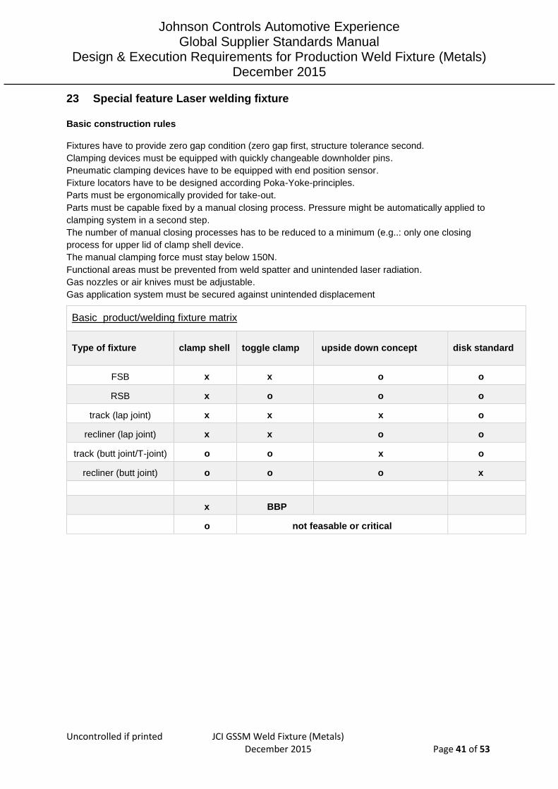
Basic product/welding fixture matrix
Type of fixture clamp shell toggle clamp upside down concept disk standard
FSB x x o o
RSB x o o o
track (lap joint) x x x o
recliner (lap joint) x x o o
track (butt joint/T-joint) o o x o
recliner (butt joint) o o o x
x BBP
o not feasable or critical
Johnson Controls Automotive Experience Global Supplier Standards Manual
Design & Execution Requirements for Production Weld Fixture (Metals) December 2015
Uncontrolled if printed JCI GSSM Weld Fixture (Metals) December 2015 Page 42 of 53
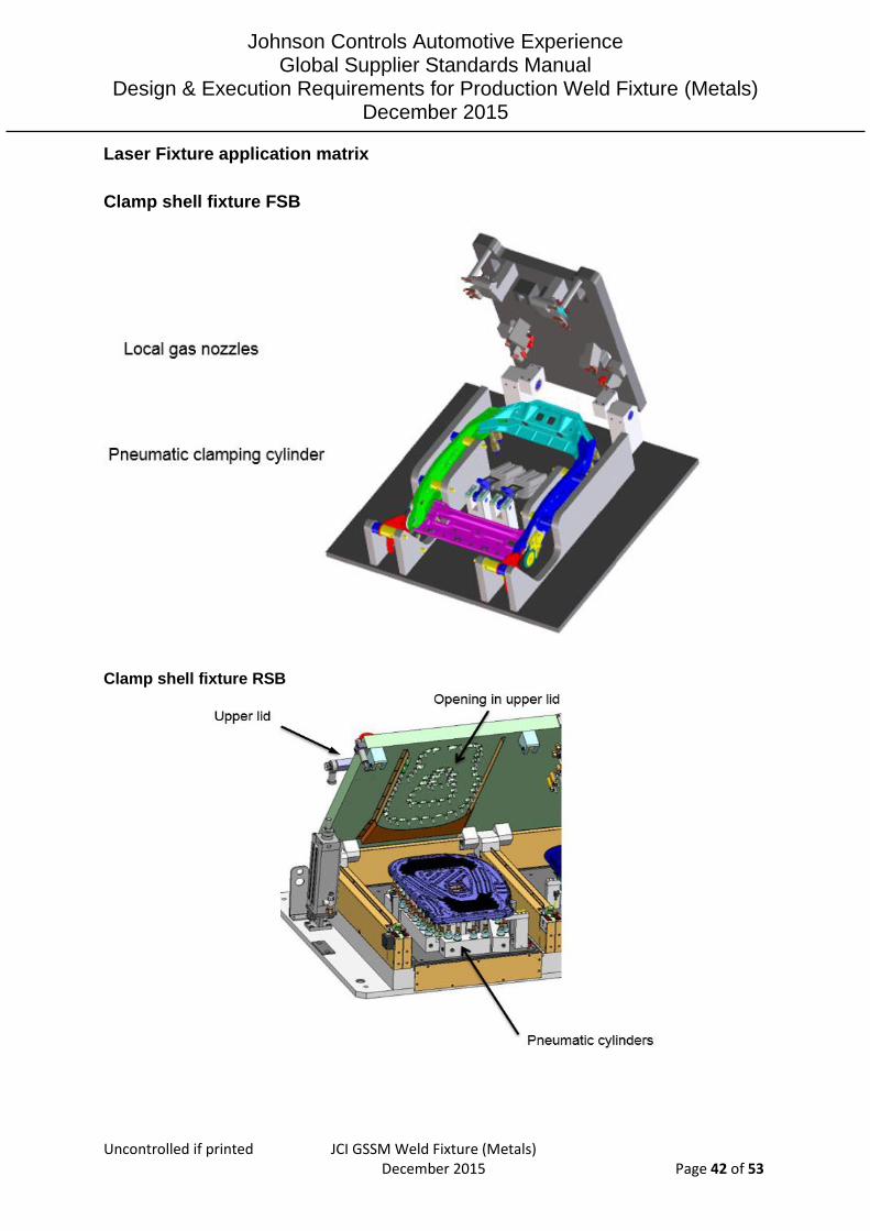
Laser Fixture application matrix
Clamp shell fixture FSB
Clamp shell fixture RSB

Johnson Controls Automotive Experience Global Supplier Standards Manual
Design & Execution Requirements for Production Weld Fixture (Metals) December 2015
Uncontrolled if printed JCI GSSM Weld Fixture (Metals) December 2015 Page 43 of 53
Beam access clamp shell fixtures (opening in upper lid)
1) Weldseam with lateral welding angle
10mm seam length: X = 1+5+2+(10+5)+2+5+1 = 31mm 15mm seam length: X = 1+5+2+(15+5)+2+5+1 = 36mm
20mm seam length: X = 1+5+2+(20+5)+2+5+1 = 41mm
The width y depends on the lateral angle, the beam cone, the seam pattern and the distance between upper lid and working point on the part
2) Weldseam with longitudinal welding angle
The length x depends on the longitudinal angle, the beam cone and the distance between the upper lid and the working point on the part
A

Johnson Controls Automotive Experience Global Supplier Standards Manual
Design & Execution Requirements for Production Weld Fixture (Metals) December 2015
Uncontrolled if printed JCI GSSM Weld Fixture (Metals) December 2015 Page 44 of 53
Toggle clamp fixture FSB
Upside down concept

Johnson Controls Automotive Experience Global Supplier Standards Manual
Design & Execution Requirements for Production Weld Fixture (Metals) December 2015
Uncontrolled if printed JCI GSSM Weld Fixture (Metals) December 2015 Page 45 of 53

Johnson Controls Automotive Experience Global Supplier Standards Manual
Design & Execution Requirements for Production Weld Fixture (Metals) December 2015
Uncontrolled if printed JCI GSSM Weld Fixture (Metals) December 2015 Page 46 of 53
Disk Standard

Johnson Controls Automotive Experience Global Supplier Standards Manual
Design & Execution Requirements for Production Weld Fixture (Metals) December 2015
Uncontrolled if printed JCI GSSM Weld Fixture (Metals) December 2015 Page 47 of 53
Basic principle ‘downholder system’ for recliner welding
24 Connection fixture reused welding cell
Observe the regional rules for NA, CN and EU
For reused equipment ask responsible AME for detailed information

Johnson Controls Automotive Experience Global Supplier Standards Manual
Design & Execution Requirements for Production Weld Fixture (Metals) December 2015
Uncontrolled if printed JCI GSSM Weld Fixture (Metals) December 2015 Page 48 of 53
25 Examples GMAW fixture solutions
Single seat backrest upper crossmember / headrest form tubes
Good working solution
Function like gripper, see next figure
Johnson Controls Automotive Experience Global Supplier Standards Manual
Design & Execution Requirements for Production Weld Fixture (Metals) December 2015
Uncontrolled if printed JCI GSSM Weld Fixture (Metals) December 2015 Page 49 of 53
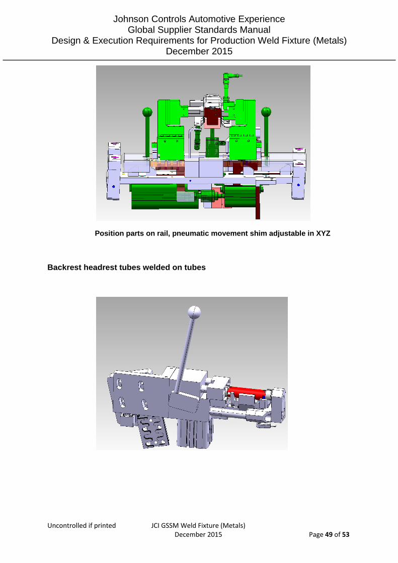
Position parts on rail, pneumatic movement shim adjustable in XYZ
Backrest headrest tubes welded on tubes
Johnson Controls Automotive Experience Global Supplier Standards Manual
Design & Execution Requirements for Production Weld Fixture (Metals) December 2015
Uncontrolled if printed JCI GSSM Weld Fixture (Metals) December 2015 Page 50 of 53
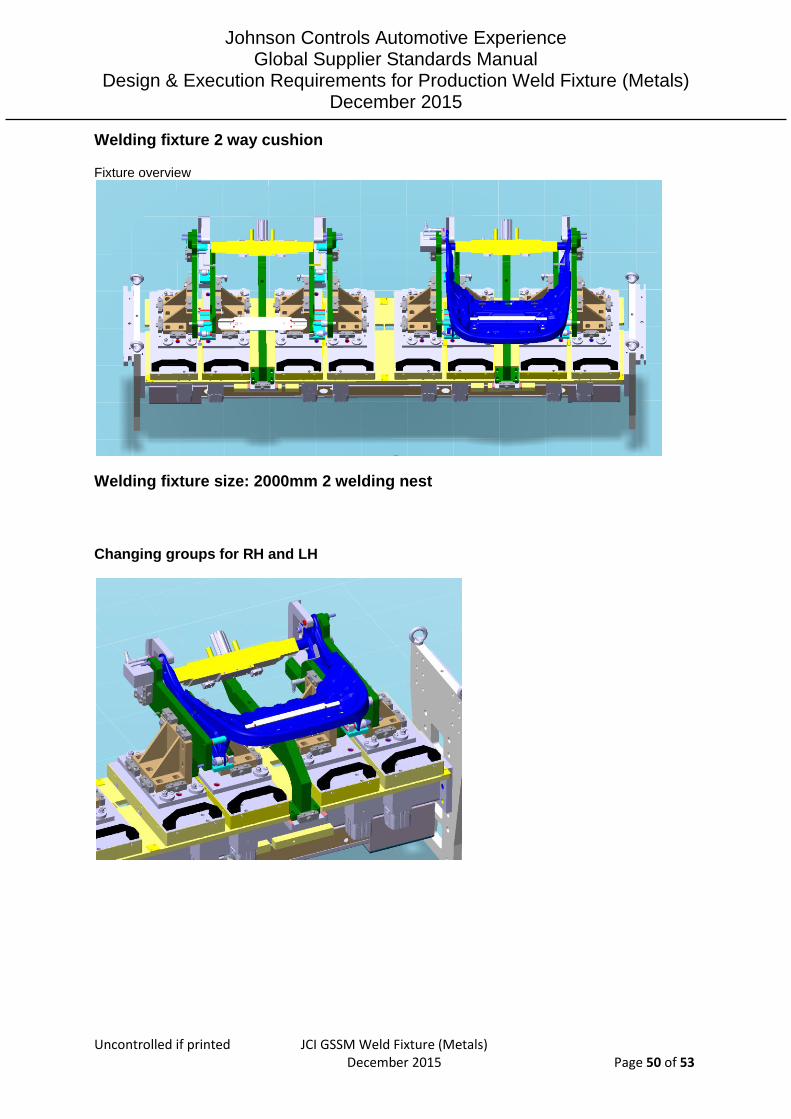
Welding fixture 2 way cushion
Fixture overview
Welding fixture size: 2000mm 2 welding nest
Changing groups for RH and LH

Johnson Controls Automotive Experience Global Supplier Standards Manual
Design & Execution Requirements for Production Weld Fixture (Metals) December 2015
Uncontrolled if printed JCI GSSM Weld Fixture (Metals) December 2015 Page 51 of 53

Johnson Controls Automotive Experience Global Supplier Standards Manual
Design & Execution Requirements for Production Weld Fixture (Metals) December 2015
Uncontrolled if printed JCI GSSM Weld Fixture (Metals) December 2015 Page 52 of 53
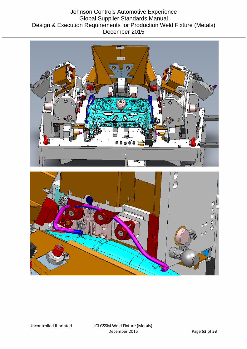
Outer sliding group
Changing unit RH / LH
Johnson Controls Automotive Experience Global Supplier Standards Manual
Design & Execution Requirements for Production Weld Fixture (Metals) December 2015
Uncontrolled if printed JCI GSSM Weld Fixture (Metals) December 2015 Page 53 of 53