jorge monroy, market development manager high …
TRANSCRIPT

High Voltage Surge ArrestersInsulation withstand and altitude
JORGE MONROY, MARKET DEVELOPMENT MANAGER

April 6, 2019 Slide 2
Fundamentals of insulation coordination
Possible voltages without arresters
Withstand voltage of equipment
Voltages limited by arrestersMag
nitu
de
of
(ove
r-)v
olt
age
/ p
.u.
1
2
3
4
0Fast-front overvoltages(μs)
Slow-front overvoltages(ms)
TOV(s)
Us(Continuously)
Time duration of (over-)voltage
COV
Um
LIWV
LIPLSIWV
SIPL
Ö31 p.u =
Us x Ö2
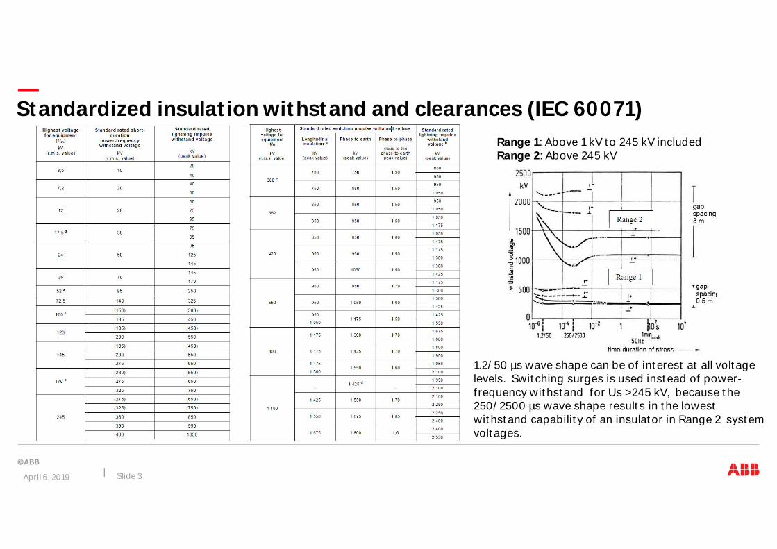
Standardized insulation withstand and clearances (IEC 60071)
April 6, 2019 Slide 3
1.2/50 µs wave shape can be of interest at all voltagelevels. Switching surges is used instead of power-frequency withstand for Us >245 kV, because the250/2500 µs wave shape results in the lowestwithstand capability of an insulator in Range 2 systemvoltages.
Range 1: Above 1 kV to 245 kV includedRange 2: Above 245 kV

Standardized insulation withstand and clearances (IEC 60071)
April 6, 2019 Slide 4

Surge arrester specifics
Arresters are self protecting and have less risk for flashover than otherequipment, provided they are dimensioned correctly
– external insulation of arresters need not fulfil a certain standardized insulationclass
– insulation requirements based on the arrester’s protection levels with areasonable safety margin added
Unnecessarily long arresters give less effective protection against steepersurges and undue mechanical stress
Clearance to other equipment generally according to IEC 60071 guidelines
– arrester characteristics also may permit reduced clearance distances inspecific cases
April 6, 2019 Slide 5

Standardized withstand & clearances
April 6, 2019 Slide 6
NOT applicable to surge arrestersas permitted by IEC 60071-1
5.5 Selection of the rated insulation level
“For surge arresters the required withstandvoltages of the insulating housing are based onthe protective levels Upl and Ups with suitablesafety factors applied as per the apparatusstandard IEC 60099-4. In general, therefore, thewithstand voltages shall not be selected fromthe lists of 5.6 and 5.7”

Standardized withstand & clearances
April 6, 2019 Slide 7
NOT applicable to surge arrestersas permitted by IEC 60099-5 (Clause 5.2.2.2)
Often users are not aware of this special situation forsurge arresters and would require the standard valuesof IEC 60071-1:2010 (Tables 2 and 3). This leads tounnecessarily tall arrester housings, which is not only aproblem of geometrical dimensions but also results inan adverse axial voltage distribution and possibly in amore critical performance under polluted conditions.There may be special situations, such as extremeenvironmental conditions, that require higher impulsewithstand ratings, but in general only the requirementsof IEC 60099-4 should be applied.

As per IEC 60099-4, up to 1000masl for < 800kV
LIWV (dry) > 1.3 x Uplobtained from 1.15 x e(1000/8150)
which reflects a 15% co-ordination factor to take into account discharge currentshigher than nominal and the statistical nature of the withstand voltage of theinsulation, and a 13% margin to account for variation in air pressure from sea levelup to normal service altitudes not exceeding 1 000 m and discharge currents higherthan nominal.
SIWV (wet) > ~1.25 x Upsobtained from 1.1 x e(1000/8150)
which reflects a 10% co-ordination factor to take into account discharge currentshigher than normal and the statistical nature of the withstand voltage of theinsulation, and a 13% margin to account for variation in air pressure from sea levelup to normal service altitudes not exceeding 1 000 m
PFWV (wet) > 1.06 x Ups (as peak value), 1 minute withstandThe factor of 1,06 takes into account a safety margin of 1,1 for higher switchingimpulse currents, an altitude correction factor of 1,13 for 1000 m installationaltitude, and a test conversion factor of 0,6×√2 according to Table 2 of IEC 60071-2.
The correction factor (Ka) isbased on the dependence of theatmospheric pressure at thealtitude.
whereH is the altitude above sea level(in metres) and the value of m is
Lightning m = 1,0
Switching< 800kV m = 1,0> 800 kV m according to
fig 9 IEC 60071-2
April 6, 2019 Slide 8
Surge arrester withstand & clearances

April 6, 2019 Slide 11
Surge arrester withstand & clearancesExample

April 6, 2019 Slide 12
Surge arrester withstand & clearancesExample

April 6, 2019 Slide 14
1HSM 9543 16-01en Edition 1, 2012-06Insulation withstand and clearancesRecommendations available

– Statistical risk of an external flashover less than or equal to 10-3 (0.1 % per year) isconsidered acceptable by IEC 60071-2
• Resultant factor between the arrester protective levels and the LIWV and SIWV of thearrester housing
– Normal installed altitude above sea level
• IEC < 1000 m
• IEEE < 1800 m (in process of changing to 1000 m)
– For higher altitudes, special consideration needs to be given on a case-by-case basis.
– Altitude correction methods considering
• arrester protection level
• insulation withstand level required for altitude difference over 1000 masl
• creepage distance
April 6, 2019 Slide 15
Altitude correction

Air pressure
– The normal value of air pressure at mean sea level is 101.3 kPa.
• Depending on meteorological conditions, air pressure atsea-level may vary from approximately 91% to 107% of this value
• In areas above sea-level air pressure is lower than at sea level andin areas below sea-level higher than at sea level.
Altitude Habove sea level(m)
Air pressure(kPa)
Relative air pressureat altitude
Calculated Ka= e(H/8150)
0 101.3 1 1
1000 89.9 1.13 1.13
2000 79.5 1.27 1.28
3000 70.1 1.45 1.44
4000 61.6 1.64 1.63
5000 54.0 1.88 1.85
An altitude correctionfactor (Ka) based on thedependence of theatmospheric pressure onthe altitude, can becalculated from
where H is the altitudeabove sea level (inmetres) and with thecoordination factor, m,conservatively taken toequal 1.0 for Us < 800 kV.
April 6, 2019 Slide 17

Altitude correctionPreferred method
April 6, 2019 Slide 18
LIWV (dry) > Upl x 1.15 x e(H/8150)
SIWV (wet) > Ups x 1.1 x e(H/8150)
PFWV (wet) > Ups x 1.1 x e(H/8150) x 0.6 x √2 (as peak value)

April 6, 2019 Slide 20
Altitude correctionNon-supported methods
Based on altitude difference over 1000m Based on creepage distance
– Standardized insulation withstand x Ka
– Presumes equipment is directly designedfor use at 1000 masl
– Less conservative, but may besuitable/necessary in some cases
– Pollution withstand already catered for up to the design altitude;only the altitude above 1000 m needs to be corrected. Experiencesuggest m = 0.5 should be used for AC applications whencorrecting creepage distance.
– Method arguably warranted for hydrophilic surfaces, eg. porcelain,if they can become at risk of flashover due to dry-band relateddischarge activity taking place. Such an issue is less of a concernfor hydrophobic transfer materials, eg. silicone, and the need tocorrect creepage distance on these insulators is doubtful.
– Intent should be to first determine the necessary creepagedistance according to pollution conditions at the actual altitudeand then correct only that value for altitude.
