kla series - amazon simple storage service€¦ · the kla series brings the power and...
TRANSCRIPT

KLA12 – 12" 2-way Loudspeaker
KLA181 – 18" Subwoofer
KLA AF12 – Array Frame
KLA SeriesUser Manual
TD-000319-00-A
*TD-000319-00*
2
EXPLANATION OF SYMBOLS
The term “WARNING!” indicates instructions regarding personal safety. If the instructions are not followed the result may be bodily injury or death.
The term “CAUTION!” indicates instructions regarding possible damage to physical equipment. If these instructions are not followed, it may result in damage to the equipment that may not be covered under the warranty.
The term “IMPORTANT!” indicates instructions or information that are vital to the successful completion of the procedure.
The term "NOTE" is used to indicate additional useful information.
The intent of the lightning flash with arrowhead symbol in a triangle is to alert the user to the presence of un-insulated "dangerous" voltage within the product's enclosure that may be of sufficient magnitude to constitute a risk of electric shock to humans.
The intent of the exclamation point within an equilateral triangle is to alert the user to the presence of important safety, and operating and maintenance instructions in this manual.
IMPORTANT SAFETY INSTRUCTIONS
AARNRNG!: TO PREVENT FIRE OR ELECTRIC SHOCK, DO NOT EXPOSE THIS EQUIPMENT TO RAIN OR MOISTURE.
AARNRNG!: While it is possible for one person to lift a KLA12 loudspeaker, it is important to use proper lifting techniques. Suggested reading: OSHA Technical Manual on Back Disorders and Injuries (http://www.osha.gov/dts/osta/otm/otm_vii/otm_vii_1.html#app_vii:1_2).
• Keep these instructions.
• Heed all warnings.
• Follow all instructions.
• Do not use this apparatus near water.
• Clean only with a dry cloth.
• Do not block any ventilation opening. Install in accordance with the manufacturer's instructions.
• Do not install near any heat sources such as radiators, heat registers, stoves, or other apparatus (including amplifiers) that produce heat.
• Do not defeat the safety purpose of the polarized or grounding-type plug. A polarized plug has two blades with one wider than the other. A grounding type plug has two blades and a third grounding prong. The wide blade or the third prong are provided for your safety. If the provided plug does not fit into your outlet, consult an electrician for replacement of the obsolete outlet.
• Protect the power cord from being walked on or pinched particularly at plugs, convenience receptacles, and the point where they exit from the apparatus.
• Only use attachments/accessories specified by the manufacturer.
• Unplug this apparatus during lightning storms or when unused for long periods of time.
• Refer all servicing to qualified service personnel. Servicing is required when the apparatus has been damaged in any way, such as power-supply cord or plug is damaged, liquid has been spilled or objects have fallen into the apparatus, the apparatus has been exposed to rain or moisture, does not operate normally, or has been dropped.
• The appliance coupler, or the AC Mains plug, is the AC mains disconnect device and shall remain readily operable after installation. On units equipped with powerCon® connectors, the AC Mains disconnect device is the AC Mains plug only; do not use the appliance coupler.
• Adhere to all applicable, local codes.
• Consult a licensed, professional engineer when any doubt or questions arise regarding a physical equipment installation.

3
FCC Statement
ROTE!: This equipment has been tested and found to comply with the limits for a Class B digital device, pursuant to Part 15 of the FCC Rules.
These limits are designed to provide reasonable protection against harmful interference in a residential installation. This equipment generates, uses and can radiate radio frequency energy and, if not installed and used in accordance with the instructions, may cause harmful interference to radio communications. However, there is no guarantee that interference will not occur in a particular installation. If this equipment does cause harmful interference to radio or television reception, which can be determined by turning the equipment off and on, the user is encouraged to try to correct the interference by one or more of the following measures:
• Reorient or relocate the receiving antenna.
• Increase the separation between the equipment and receiver.
• Connect the equipment into an outlet on a circuit different from that to which the receiver is connected.
• Consult the dealer or an experienced radio/TV technician for help.
Warranty (USA only; other countries, see your dealer or distributor)
QSC Audio Products 3 Year Limited Warranty
QSC Audio Products, LLC (”QSC”) guarantees its products to be free from defective material and/or workmanship and will replace defective parts and repair malfunctioning products under this warranty when the defect occurs under normal installation and use, provided the unit is returned to our factory, one of our authorized service stations or an authorized QSC International Distributor via pre-paid transportation with a copy of proof of purchase (i.e., sales receipt). This warranty provides that the examination of the return product must indicate, in our judgment, a manufacturing defect. This warranty does not extend to any product which has been subjected to misuse, neglect, accident, improper installation, or where the date code has been removed or defaced. QSC shall not be liable for incidental and/or consequential damages. This warranty gives you specific legal rights. This limited warranty is freely transferable during the term of the warranty period. The warranty on QSC products is NOT VALID if the products have been purchased from an unauthorized dealer/online e-tailer, or if the original factory serial number has been removed, defaced, or replaced in any way. Damage to, or loss of any software or data residing on the product is not covered. When providing repair or replacement service, QSC will use reasonable efforts to reinstall the product’s original software configuration and subsequent update releases, but will not provide any recovery or transfer of software or data contained on the serviced unit not originally included in the product.
Customers may have additional rights, which vary from state to state or from country to country. In the event that a provision of this limited warranty is void, prohibited or superseded by local laws, the remaining provisions shall remain in effect.
The QSC limited warranty is valid for a period of three (3) years from date of purchase in the United States and many (but not all) other countries.
For QSC warranty information in countries other than the United States, contact your authorized QSC international distributor. A list of QSC International distributors is available at www.qscaudio.com.
To register your QSC product online, go to www.qscaudio.com and select ”Product Registration”. Other questions regarding this warranty can be answered by calling, e-mailing or contacting your authorized QSC distributor.
Phone: 1-800-854-4079 within US and Canada, +1-714-754-6175 international, Email: [email protected], Website: www.qscaudio.com.
4
Suspending the KLA Series Loudspeakers
AARNRNG!: Read and follow these instructions carefully. If the loudspeakers are not suspended properly, they could fall, causing personal injury and damage to the equipment.
Rules for Suspension
• Consult a professional mechanical or structural engineer, licensed in the jurisdiction of the sound system installation, to review, verify, and approve all attachments to the building or structure.
• Employ the services of a certified, professional rigger for hoisting, positioning, and attaching the equipment to the supporting structure.
• Correct use of all suspension hardware and components is imperative in sound system suspension and deployment.
• Always calculate suspended loads before lifting to make sure suspension components and hardware are used within their respective load limits.
• Consult local codes and regulations to fully understand the requirements for suspended loads in the venue in which you will suspend the equipment.
• Use only the KLA AF12 Array Frame or the M10 installation points for suspending the array.
• Be absolutely certain of the integrity of any structural member intended to support suspended loads. Hidden structural members can have hidden structural weakness.
• Never assume anything! Owner or third-party supplied suspension attachment points may not be adequate for suspending the loads.
• Before lifting, always inspect all components (enclosures, suspension brackets, pins, frames, bolts, nuts, slings, shackles, etc.) for cracks, wear, deformation, corrosion, missing, loose, or damaged parts that could reduce the strength of the assembly. Discard any worn, defective, or suspect parts and replace them with new appropriately load-rated parts.
Shock Loading
When a load is either moved or stopped, its static weight is magnified. Sudden movements can magnify the static weight several times. This magnification of static weight is called "shock loading". Shock loading poses a danger to equipment and workers. The effects of shock loading can be instantaneous, or may remain undetected unless the equipment is visually damaged. Proper preparation for shock loading requires careful planning and knowledge of equipment, suspension, and lifting practices.
Shock loading of equipment and structures is usually confined to lifting and installation, but natural forces (winds, earthquakes, and so on) can impose shock loads several times the static load. Because of this, structures and suspension equipment must be capable of supporting several times the weight of the suspended equipment.
KLA Maximum Suspended Load
The KLA components are engineered for a 10:1 design factor.
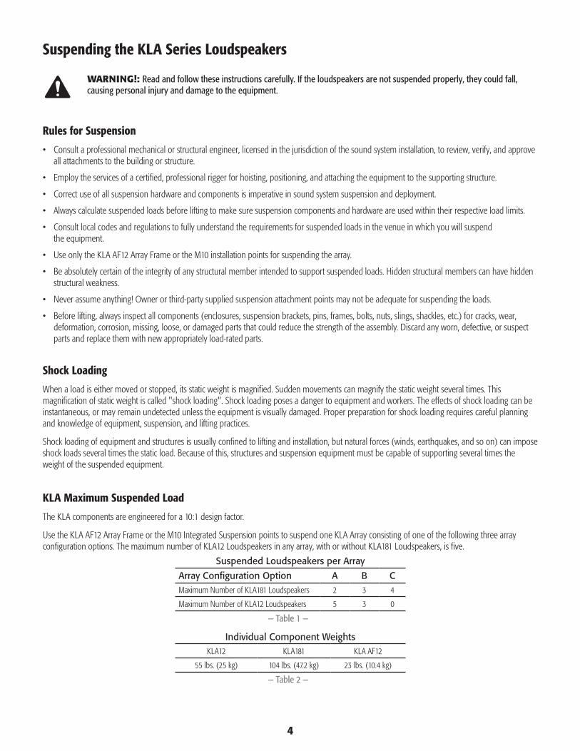
Use the KLA AF12 Array Frame or the M10 Integrated Suspension points to suspend one KLA Array consisting of one of the following three array configuration options. The maximum number of KLA12 Loudspeakers in any array, with or without KLA181 Loudspeakers, is five.
Suspended Loudspeakers per Array
Array Configuration Option A B CMaximum Number of KLA181 Loudspeakers 2 3 4
Maximum Number of KLA12 Loudspeakers 5 3 0
— Table 1 —
Individual Component WeightsKLA12 KLA181 KLA AF12
55 lbs. (25 kg) 104 lbs. (47.2 kg) 23 lbs. (10.4 kg)
— Table 2 —

5
IntroductionThe KLA Series brings the power and sophistication of a line-array system into an easy-to-use product significantly redefining the line-array-product category. With its simple Lift, Click and Play approach, KLA deploys in a fraction of the time required by comparable line-array products. This fixed arcuate, active line-array system is ideal for a wide range of portable and permanently installed applications ranging from live entertainment to houses of worship or other venues where a line-array system is desired.
The KLA Series is comprised of two models: the KLA12 12-inch, 2-way loudspeaker and the KLA181 18-inch subwoofer. The KLA12 features a highly efficient 500 W x 500 W power-amp module in a rugged, lightweight ABS enclosure that can be used in multiple configurations using QSC's unique SOLO™ (Single-Operator Logistics) Rigging System and/or Tilt-Direct™ 35 mm pole socket. The KLA181 offers the same highly efficient power-amp module in a 1,000 W configuration in a birch plywood enclosure. KLA Series loudspeaker models incorporate:
QSC’s DEEP™ DSP algorithm, providing extended bass response by actively managing potentially damaging low-frequency transients,
GuardRail™ circuitry protection that prevents the amplifier module from unnatural and destructive clipping,
Intrinsic Correction™ (KLA12) to correct for inherent characteristics of the loudspeakers, waveguide, and enclosures,
Ar-Q™ to make equalization adjustments based on the number of KLA12s in the array,
Auto Standby mode that automatically engages after five minutes of inactivity, but upon resumption of audio signal, the power module on the KLA awakens instantly for immediate output.
Remote Gain control capability in an installed application using a single potentiometer wired to a Euro-style connector.
Balanced, line-level XLR input, in parallel with an XLR output, for distributing the audio signal to multiple loudspeakers.
powerCON® AC In and AC Out connectors for powering up to five loudspeakers on a single 15 amp/120 V (8 amp/240 V) electrical circuit.
Other features include LED indicators for Signal and Limit, and discrete LED indicators for Power/Standby status.
UnpackingKLA12 Package Contents1. Quick-Start Guide
2. Warning Information Sheet
3. KLA12 Speaker Assembly
4. AC powerCON® Power Cord (CEE 7/7), 3.6 Meter
5. AC powerCON® Power Cord (NEMA 5-15 - USA style), 12 Foot
6. XLR Audio Loop-thru Cable, 2 Foot
7. powerCON® Loop-thru Power Cord, 2 Foot
8. Euro-style Connector Plug, 3-pin
KLA181 Package Contents1. Quick-Start Guide
2. Warning Information Sheet
3. KLA181 Subwoofer Assembly
4. AC powerCON® Power Cord (CEE 7/7), 3.6 Meter
5. AC powerCON® Power Cord (NEMA 5-15 - USA style), 12 Foot
6. XLR Audio Loop-thru Cable, 3 Foot
7. powerCON® Loop-thru Power Cord, 3 Foot
8. Hex Key, 6 mm
9. Euro-style Connector Plug, 3-pin

6
Features
KLA12
— Figure 1 —
1
2
3
4
99
56
7
8
8 8
8
66
4
44
8
1. ABS enclosure
2. Steel grille
3. Front power LED
4. Handles
5. Power module
6. M10 installation points (3)
7. Tilt-Direct™ dual angle (0° or -9°) pole socket
8. Slip-resistant feet
9. Side Rigging Plates

7
KLA181
— Figure 2 — — Figure 3 —
0˚ -9˚
— Figure 4 —
— Figure 5 —
0˚
1. Baltic Birch enclosure
2. Steel grille
3. Front power LED
4. Handles
5. Power module
6. M10 installation points (4)
7. Slip-resistant feet
8. M20 threaded, 35 mm pole mount
9. Side rigging plates
10. Feet alignment receptacles

8
KLA AF12
(Shown as shipped)
1. Rigging pins and lanyard (2)
2. Array extension beam
3. Array frame
4. Feet for KLA181 application
5. Feet for KLA12 application
— Figure 6 —
1
2
3
4
5

9
Application
The KLA Series can be configured in an array with combinations of loudspeakers, refer to "KLA Maximum Suspended Load" on page 4. Using SOLO™ (Single-Operator Logistics), box-to-box attachment of the KLA12 is simple, self-contained, and requires no tools or additional hardware. The KLA181 requires an 6 mm hex key (supplied) for box-to-box and KLA AF12 deployment, and a 6 mm hex key for M10 suspension. You can suspend the array using the KLA AF12 Array Frame or the M10 installation eyebolts.
Up to two KLA loudspeakers may be used on a tripod (Figure 5) or on a pole, no longer than 36 in. (914 mm), over the KLA181 (or KW181) subwoofer (Figure 6). The KLA12 is equipped with QSC's Tilt-Direct™ 35 mm pole socket to allow a zero or 9° downward tilt of the loudspeakers for the best audience coverage when deployed on a tripod or over the subwoofer.
You can attach up to two KLA12 loudspeakers together, and place them on top of a KLA181 subwoofer. The integrated dove-tail foot on the KLA12 ensures a 0° angle making it ideal for front fill, or stage lip deployment (Figure 7).
Preparing the KLA for Suspension
AARNRNG!: The KLA181 weighs 104 lbs. (47.2 kg) and the KLA12 weighs 55 lbs. (25 kg) Use proper lifting techniques to complete this procedure. Refer to "KLA Maximum Suspended Load" on page 4.
AARNRNG!: Make sure that the loudspeakers are properly aligned; if not, the latching system may not properly engage, and the loudspeakers could separate causing physical damage, and/or personal injury. The top of a unit should be parallel to the bottom of the unit above.
AARNRNG!: During assembly/disassembly, make sure the components are properly supported throughout the entire process.
NIMOATART!: In all cases, when you attach the loudspeakers together or to the array frame, you are attaching the bottom unit to the one above, using the attaching mechanism on the bottom unit.
AATNORG!: QSC recommends lifting the KLA12 loudspeaker from the rear to avoid blemishing the grille. In addition, to protect the latching mechanism, QSC recommends that you return the hooks to the retracted position, and lock lever "B" down when transporting the loudspeakers.
The KLA12 loudspeakers, when attached together, are a fixed-arcuate line array with splay angles of 18° matching the individual loudspeaker's vertical dispersion angle of 18°. The KLA12 features QSC's SOLO™, allowing you to attach KLA12s together with one person, and no tools.
— Figure 7 — — Figure 8 —
0˚ -9˚
— Figure 9 —
— Figure 10 —
0˚

10
Attaching a KLA12 to a KLA12 or KLA AF12 Array Frame
The KLA12 loudspeakers come with the attaching hooks in the retracted position, indicated by the slide (1) down, and the lever "B" in the down, or locked position as shown in Figure 8.
1. Move the lever button (Figure 8, 2) upwards, and then rotate lever "B" up, as shown, until it stops.
2. Make sure that levers labeled "B" and slides (1) on both sides of the bottom loudspeaker are in the positions shown in Figure 9. If not, repeat Step 1, then push button "A" and move the slide (1) to the down position.
3. When attaching the KLA AF12 Array Frame, make sure the KLA12 feet are pointing down as shown in Figure 10. In addition, the array frame is reversible, front to back. The direction the Extension Bar points changes tilt capability of the array. Refer to "Using the KLA AF12 Array Frame" on page 14 for detailed information about the array frame.
4. Place one KLA12, or KLA AF12 Array Frame, on top a KLA12 as shown in Figure 10. Make sure that the four non-slip feet (1) on the bottom of the top unit nest into the feet receptacles (2) on the top of the bottom loudspeaker.
5. Make sure the top surface and the bottom surface of the units are parallel, and the front and back edges are aligned as shown in Figure 11.
Refer to Figure 12.
6. On the bottom loudspeaker, the hook (Figure 12, 2) is in the Retracted Position. Push button "A" to release the slide (1). The slide automatically slides upward, and the hook (4) automatically rotates to the Up Position.
7. On the bottom loudspeaker, pull lever "B" (Figure 12) downward to lock the hook (5) in the Locked Position and secure the loudspeakers.
AARNRNG!: Make sure that the lever "B" locks in the down, Locked Position. If not properly latched, the loudspeakers could separate and cause physical damage to the loudspeakers, and/or personal injury.
8. Repeat the procedure for the other side of the loudspeaker, and for all KLA12 loudspeakers in the array. The loudspeakers are ready to suspend.
— Figure 11 —
2 1
— Figure 12 —
1
— Figure 13 —
1
2
A B
— Figure 14 —
ParallelParallel
— Figure 15 —
ROTATE DOWN
5
2
1
B
4
SLIDES UPPUSH

11
Attaching a KLA12 to a KLA181
The KLA12 cannot be attached to the top of a KLA181.
There are various ways to facilitate attaching a KLA12 to a KLA181, and they vary depending on the specific circumstances. Be sure to use proper rigging techniques, and/or employ a professional engineer. Following is one example.
Suspend the KLA181 as described in "Suspending the KLA Array" on page 14, then carefully attach a KLA12 to the bottom of the KLA181 using the KLA12 attaching mechanism. Continue attaching the remaining KLA12s to the array.
1. Make sure that levers (1) and slides (2) (on both sides of the KLA12 loudspeaker), are in the positions shown in Figure 9 on page 10.
Refer to Figure 13.
2. Place the top of the KLA12 up to the bottom of the KLA181 such that the front feet on the KLA181 nest into the feet receptacles on the top of the KLA12. The front and sides of the KLA12 should be aligned with the front and sides of the KLA181.
Refer to Figure 14
3. On the KLA12 loudspeaker with the hook (2) in the Retracted Position, push button "A" to release slide (1). Slide (1) automatically moves upward, and the hook (2) automatically rotates to the Up Position. In the Up Position, the hook fills the view hole (3) in the KLA181.
4. On the KLA12 loudspeaker, pull lever "B" downward to lock the hook (2) in the Locked Position and secure the loudspeakers. When the hook (2) is properly latched, you can only see a portion of the hook (2) through the view hole (3).
AARNRNG!: Make sure that the lever "B" locks in the downward, Locked Position indicating that the hook itself is locked. If the locking mechanism is not properly latched, the loudspeakers could separate and cause physical damage to the loudspeakers, and/or personal injury.
5. Repeat the procedure for the other side of the loudspeakers, and for all KLA12 loudspeakers in the array. The loudspeakers are ready to suspend.
— Figure 16 —
— Figure 17 —
2
1
A
B
3
2
1
B
3
B 2
3

12
Separating a KLA12 from a KLA AF12 Array Frame, KLA12, or KLA181
Refer to Figure 15.
1. Safely support the bottom KLA12 in the array. You must support both sides of the loudspeaker, and relieve the weight of the loudspeaker from its latching mechanism in order to separate one loudspeaker from another.
2. Move the lever button (1) upward, and then rotate lever "B" up, as shown, until it stops.
3. Push the slide (2) downward to rotate the hook (not shown) to the retracted position. You will not be able to perform this step unless the weight of the loudspeaker is relieved from the latching mechanism.
4. If you are going to transport the loudspeakers, rotate lever "B" down until it locks. The hooks are locked in the Retracted Position.
5. Repeat for the other side of the loudspeaker. The loudspeaker can now be separated from the unit above.
Attaching a KLA181 to a KLA181
1. With the KLA181 on the floor, or other suitable surface, insert the supplied 6 mm hex key into the hex socket (Figure 17, 4) and make sure the hex key is rotated completely to the Unlock position as noted next to the hex socket on the loudspeaker. The attaching hooks on the top of the loudspeaker are now in the retracted position.
Refer to Figure 16.
2. Place another KLA181 on top of the first with the loudspeakers facing the same direction. Make sure that the four feet (1) on the top KLA181 nest properly with the four feet receptacles on the top of the bottom KLA181. When properly nested, you should not be able to move or slide the top unit without lifting it.
Refer to Figure 17.
ROTE!: The bottom portion of Figure 17 shows the motion of the hook during the latching process. This is not visible on the actual hardware.
3. Insert the 6 mm hex key (supplied) into the hex socket (4) in the lower KLA181.
4. Turn the key fully to the Locked Position as noted next to the hex socket on the loudspeaker. As you turn the key, you can see the hook (3), through the view holes (1), moving to its final, Locked Position.
a. In the Retracted Position, you cannot see the hook in the view holes.
b. When the hook reaches the Up Position, the hook almost completely fills the large viewing hole at the top.
c. In the final, Locked Position, you can see a small portion of the hook in the bottom of the large viewing hole.
5. Repeat for the other side of the loudspeaker. The loudspeakers are securely attached to one another and ready for suspension.
— Figure 18 —
1 2
— Figure 19 —
1
2
— Figure 20 —
1
2
3
LockedPosition
UpPosition
RetractedPosition
1
4

13
Attaching a KLA181 to a KLA AF12 Array Frame
Refer to Figure 18
ROTE!: The KLA AF12 Array Frame must be oriented with the KLA181 feet pointing down as shown in Figure 18. For more detail, refer to Figure 3 on page 8.
1. Place the KLA181 on the floor, or other suitable surface, and make sure the hooks are retracted. If not, insert the supplied 6 mm hex key into the hex socket (Figure 17, 4 on page 12) and rotate the key fully to the Unlocked Position as noted next to the hex socket on the loudspeaker.
2. Place the KLA AF12 Array Frame on top of the KLA181. The Array Frame feet (2) align, and nest into, the spaces (1) in front of and behind the attaching hook in the KLA181 rigging plates. When properly nested, you should not be able to move or slide the top unit without lifting it.
ROTE!: The KLA AF12 is reversible front to back, you can mount it on the loudspeaker with the Extension Bar pointing either direction. Point the Extension Bar pointing towards the front of the array for maximum upward tilt, towards the rear of the array for maximum downward tilt.
Refer to Figure 19
3. Insert the 6 mm hex key (supplied) into the hex socket (1) in the KLA181.
4. Turn the key fully to the Locked Position as noted next to the hex socket on the loudspeaker. Refer to Figure 17 on page 12 for details
a. In the Retracted Position, you cannot see the hook in the view hole (2).
b. When the hook reaches the Up Position, the hook almost completely fills the view hole (2) in the KLA AF12 Array Frame.
c. In the final, Locked Position, you can see a small portion of the hook in the bottom of the view hole.
5. Repeat for the other side of the loudspeaker. At this point, the loudspeaker and array frame are securely attached and are ready for suspension.
Separating a KLA181 from a KLA181 or KLA AF12
Refer to Figure 20
1. Place the two assembled KLA181 loudspeakers (or loudspeaker and array frame) on the floor or other suitable surface. If the two loudspeakers are suspended, lower them until the weight of both loudspeakers is completely supported by the floor or suitable surface.
2. Insert the 6 mm hex key into the hex socket (1) on the side of the lower KLA181.
3. Turn the hex key fully to the Unlocked Position as noted next to the hex socket on the loudspeaker. If the weight of the loudspeaker(s) is not completely supported from the bottom, you will not be able to turn the hex key fully to the Unlocked Position, or separate the units.
4. Repeat on the other side of the loudspeaker.
5. You can now separate the units.
— Figure 21 —
1
2
— Figure 22 —
KLA-AF12
KLA181
2
1
— Figure 23 —
1

14
Suspending the KLA Array
AARNRNG!: Review the topic "Rules for Suspension" on page 4. The maximum number of KLA 12 Loudspeakers in any array, with or without KLA 181 Loudspeakers, is five.
Suspended Loudspeakers per Array
Array Configuration Option A B CMaximum Number of KLA181 Loudspeakers 2 3 4
Maximum Number of KLA12 Loudspeakers 5 3 0
— Table 3 —
Individual Component WeightsKLA12 KLA181 KLA AF12
55 lbs. (25 kg) 104 lbs. (47.2 kg) 23 lbs. (10.4 kg)
— Table 4 —
AARNRNG!: Consult a professional mechanical or structural engineer, licensed in the jurisdiction of the sound system installation, to review, verify, and approve all attachments to the building or structure. Employ the services of a certified, professional rigger for hoisting, positioning, and attaching the equipment to the supporting structure.
You can suspend a KLA Array in one of two ways: using the KLA AF12 Array Frame, or using Integrated Suspension points and eyebolts.
Using the KLA AF12 Array Frame
You can attach the KLA AF12 Array Frame to the KLA12 or the KLA181 for suspension.
The Array Frame Extension bar is shown, in Figure 3 on page 8, in its shipping configuration. You must remove the rigging pins and the Extension Bar, then reassemble the array frame as follows.
Assembling the KLA AF12 Array Frame
Refer to Figure 21.
1. The array frame is oriented differently depending on the KLA loudspeaker on which it is installed.
a. For the KLA12, the wider-spaced feet are facing down.
b. For the KLA181, the narrower-spaced feet are facing down.
2. Align and insert the Extension Bar (1) into the attachment brackets (2) on the array frame.
a. Extended Portion pointing towards the rear of the array for maximum downward-tilt capability.
b. Extended Portion pointing towards the front of the array for maximum upward-tilt capability.
3. Insert the two Rigging pins (3) through the attachment brackets (2), and the Extension Bar. Make sure the pins extend through the other side of the attachment brackets, and are secure.
4. To attach the KLA AF12 Array Frame
• For a KLA12, follow all the instructions for "Attaching a KLA12 to a KLA12 or KLA AF12 Array Frame" on page 10.
• For a KLA181, follow the instructions for "Attaching a KLA181 to a KLA AF12 Array Frame" on page 13.
— Figure 24 —
1
3
2
Extended Portion
— Figure 25 —
KLA181
KLA12

15
Attach the Rigging Cables to the KLA AF12 Array Frame
You can achieve different tilt angles by attaching the suspension cabling to one of the 12 holes in the Extension Bar. The front-to-back orientation of the Extension Bar determines if the array is tilted up or down. As the suspension cabling is moved towards the Extended Portion of the Extension Bar (Figure 21), the tilt angle is increased.
Attach the KLA AF12 Array Frame to the suspension structure using a 5/8” (16 mm) screw pin anchor shackle and appropriate sling, cable, etc.
Using the KLA12 Integrated Suspension Points
Refer to Figure 23.
ROTE!: The KLA12 suspension points are designed for use with the eyebolts (M10, 20 mm) and washers included in the available M10 accessory kit (model number: K Series M10 KIT).
1. Remove the rubber plug (1) from the KLA12 rear M10 installation point.
2. Place one of the supplied washers (2) on each supplied eyebolt.
3. Thread an eyebolt (3) into each of the threaded inserts.
4. Tighten the eyebolts until their shoulders are snug against the washer/enclosure.
5. Continue to rotate the eyebolts until they reach the desired position. Do not overtighten.
6. The loudspeakers are ready for suspension.
Using the KLA181 Integrated Suspension Points
Refer to Figure 24.
ROTE!: The KLA181 suspension points are designed for use with the eyebolts (M10 X 1.50, 35 mm – 38 mm) included in the available accessory kit (model number: KLA181 M10 KIT).
1. Use a 6 mm hex key to remove the four hex screws from the four KLA181 M10 installation points on the top of the loudspeaker.
2. Thread an eyebolt into each of the threaded inserts.
3. Tighten the eyebolts until their shoulders are snug against the enclosure.
4. Continue to rotate the eyebolts until they reach the desired position. Do not overtighten.
5. The loudspeakers are ready for suspension.
Pole-mounting the KLA12
Refer to Figure 25
You can mount up to two KLA12 loudspeakers on a loudspeaker pole over the KLA181 or KW181 subwoofer, or on a loudspeaker tripod. To mount over a KLA181 or KW181 subwoofer:
1. Thread the loudspeaker pole into the M20 threaded, 35 mm pole mount on the top of the KLA181 subwoofer. Hand tighten.
ROTE!: The KLA181 threaded pole mount complies with EIA 636, Recommended Loudspeaker Safety Practices standard.
— Figure 26 —
1
2
3
— Figure 27 —
— Figure 28 —
16
AARNRNG!: Do not mount more than two (2) KLA12 loudspeakers on a pole over the KLA181 subwoofer, KW181 subwoofer or on a loudspeaker tripod. Do not use a pole longer than 36 inches (914 mm) when supporting one or two KLA12s over a KLA181 or KW181 subwoofer.
1. Adjust the QSC Tilt-Direct™ dual angle pole socket to the zero (default) position or the 9° position.
2. Carefully place one KLA12 on the loudspeaker pole by inserting the pole completely into the QSC Tilt-Direct™ pole socket. Use proper lifting techniques.
3. If you want to mount two KLA12 loudspeakers on the pole, after you place the first loudspeaker on the pole, attach the top one using the procedure "Attaching a KLA12 to a KLA12 or KLA AF12 Array Frame" on page 10.
Cooling in Installed ApplicationsThe KLA Series is an internally-powered loudspeaker containing a power amplifier that produces heat. Allow a minimum of 6" (152 mm) clearance at the rear of the enclosure for cooling. Do not restrict airflow to the rear of the speaker enclosure.
AATNORG!: Do not install enclosures with their rear panels exposed to direct sunlight. Direct sunlight will heat the amplifier module and reduce its ability to produce full output. Install sunshades if the application merits. Maximum ambient temperature for full performance to specification is 50° C (122° F). Do not install enclosures where exposed to rain or other water sources. The enclosure is not weatherproof. Outdoor installations must provide protection from the elements.
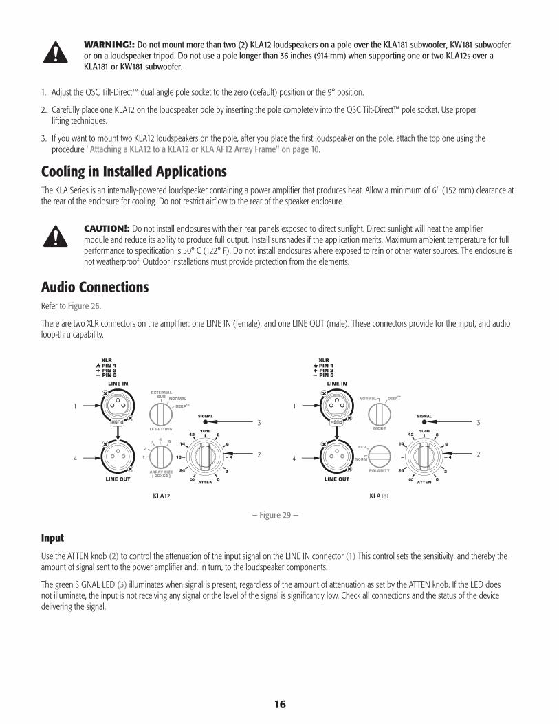
Audio ConnectionsRefer to Figure 26.
There are two XLR connectors on the amplifier: one LINE IN (female), and one LINE OUT (male). These connectors provide for the input, and audio loop-thru capability.
Input
Use the ATTEN knob (2) to control the attenuation of the input signal on the LINE IN connector (1) This control sets the sensitivity, and thereby the amount of signal sent to the power amplifier and, in turn, to the loudspeaker components.
The green SIGNAL LED (3) illuminates when signal is present, regardless of the amount of attenuation as set by the ATTEN knob. If the LED does not illuminate, the input is not receiving any signal or the level of the signal is significantly low. Check all connections and the status of the device delivering the signal.
— Figure 29 —
3
2
1
3
2
1
KLA12 KLA181
4 4

17
Balanced Inputs: Connect to the plug as shown. Unbalanced Inputs: Connect to the plug as shown.
Output
Both the KLA12 and KLA181 have discrete, direct LINE OUT male XLR connectors (Figure 26, 4), wired in parallel with the LINE IN. The signal on the LINE OUT is exactly equivalent to the signal on the LINE IN.
The level of the signal on the LINE OUT XLR is not affected by the ATTEN setting for that loudspeaker.
Making Audio Connections
Refer to Figure 26 and Figure 29.
The loop-thru cables supplied in the package are designed for use in a single array.
1. Connect the audio source (male XLR plug) to the LINE IN female XLR connector (1) on the amplifier.
2. If you are using the audio loop-thru connections, connect the female end of an XLR Audio Loop-thru Cable (supplied) to the LINE OUT connector (Figure 26, 4) on the first amplifier in the loop-thru chain.
3. Connect the male end of the XLR Audio Loop-thru Cable to the LINE IN (Figure 26, 1) of the next loudspeaker amplifier in the loop-thru chain.
4. Continue this process until all the audio connections for the loudspeakers in the array are made.
System PowerFor safety reasons, it is important to follow the proper power connection and disconnection sequence as addressed in this section.
Proper power on/off sequencing can help to prevent unexpected sounds from being produced by the system (pops, clicks, thumps). These sounds are unpleasant and can take away from the overall professionalism of the presentation. Always follow the rule that loudspeakers are “last on, first off”.
ROTE!: The KLA12 employs a universal power supply, capable of operating the system with input AC power voltages ranging from 100 – 240 VAC at 50 – 60 Hz. Use only the power cable that is correct for your location.
Connect Loop-thru Power Cables
The KLA Series features a loop-thru power connector system. Using four powerCON® Loop-thru cables, and one AC powerCON® Power Cord, you can power up to a maximum of five KLA loudspeakers on a single 15 amp/120 V (8 amp/240 V) electrical circuit. The loop-thru connectors are color coded (blue = AC IN / grey = AC OUT) and keyed differently to make sure the connections are correct.
AARNRNG!: The amplifier POWER switches do not remove AC mains power from the loop-thru cables. If the AC mains is connected to one KLA12, electrical power is present on all connected loop-thru cables.
Refer to Figure 30.
1. Make sure that all AC POWER switches (1) are off.
2. Make sure that the AC mains power cord is not connected. AC mains is the last power connection in the sequence.
— Figure 30 —
1 = shield (ground)3 = minus (-)2 = plus (+)
— Figure 31 —
1 = shield (ground)3 = jumper to pin 12 = plus (+)
— Figure 32 —
LINE IN
LINE OUT
— Figure 33 —
4 (Blue)
1
3 (Grey)
18
AARNRNG!: Do not connect more than five KLA Series loudspeakers together using the loop-thru power cables (four loop-thru cables, one AC power cord). If you are using loop-thru power cables, make all loop-thru connections prior to connecting to the AC mains.
3. Insert the grey powerCON® connector, on the loop-thru cable, fully into the grey AC OUT connector (3) on the amplifier.
4. Twist the powerCON® connector clockwise until it locks in place.
5. Insert the blue powerCON® connector fully into the blue AC IN connector (4) on the next amplifier to be powered.
6. Twist the powerCON® connector clockwise until it locks in place.
7. Repeat until all of the loudspeakers (up to five loudspeakers, using four loop-thru cables) in the array are properly connected.
Connect AC Mains
Refer to Figure 30.
8. Insert the blue powerCON® connector, on the AC power cord, fully into the blue AC IN connector (4) on the first amplifier in the chain.
9. Twist the powerCON® cable connector clockwise until it locks in place.
10. Plug the other end of the power cable into the appropriate AC mains power source.
11. You may now turn on the AC power switch(es) using the Power-On procedure in this document.
Power-on Sequence
1. Bring the output level control of the mixer (or other audio source) feeding your loudspeakers to its minimum position.
2. Turn on all source devices (CD players, mixers, instruments).
3. Push in on the top of the POWER rocker switch (Figure 30, 1) to apply AC mains power to the first powered loudspeaker in the signal chain. No other loudspeaker is feeding audio signal to this one.
4. When the amplifier is turned on, the green STANDBY indicator LED and the red LIMIT indicator LED, on the amplifier panel, illuminate. After a few seconds the red LIMIT indicator and the green STANDBY go out, and the blue POWER indicator LED illuminates. Refer to Figure 31.
5. Turn on the remainder of the KLA loudspeakers in the order in which they receive audio signal first to last.
6. The level controls on your mixer may now be brought up.
Power-off Sequence
1. Bring the output level control of the mixer (or other audio source) feeding your loudspeakers to its minimum position.
2. Turn the KLA loudspeakers off, starting with the last loudspeaker in the signal chain, by pushing in on the bottom of the POWER switch (Figure 30, 1).
3. Turn off the remainder of the KLA loudspeakers in reverse of the order in which they receive audio signal — last to first.
4. Turn off all source devices.
Disconnect AC Mains
1. Use the "Power-off Sequence" on page 18 procedure and turn the AC power switches to the off position.
2. Unplug the power cable from the AC mains.
3. Disconnect all AC loop-thru cables by grasping the powerCON® cable connector, sliding the latch button away from the amplifier, twisting the powerCON® connector counterclockwise, and pulling straight out from the amplifier.
4. Remove the AC power cord by grasping the powerCON® cable connector, pressing down on the latch button, twisting the cable connector counterclockwise, and pulling straight out from the powerCON® chassis connector.
19
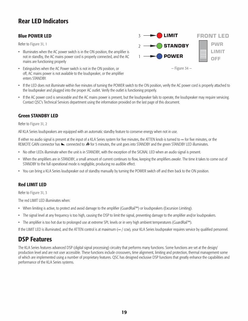
Rear LED Indicators
Blue POWER LED
Refer to Figure 31, 1
• Illuminates when the AC power switch is in the ON position, the amplifier is not in standby, the AC mains power cord is properly connected, and the AC mains are functioning properly
• Extinguishes when the AC Power switch is not in the ON position, or off, AC mains power is not available to the loudspeaker, or the amplifier enters STANDBY.
• If the LED does not illuminate within five minutes of turning the POWER switch to the ON position, verify the AC power cord is properly attached to the loudspeaker and plugged into the proper AC outlet. Verify the outlet is functioning properly.
• If the AC power cord is serviceable and the AC mains power is present, but the loudspeaker fails to operate, the loudspeaker may require servicing. Contact QSC’s Technical Services department using the information provided on the last page of this document.
Green STANDBY LED
Refer to Figure 31, 2
All KLA Series loudspeakers are equipped with an automatic standby feature to conserve energy when not in use.
If either no audio signal is present at the input of a KLA Series system for five minutes, the ATTEN knob is turned to ∞ for five minutes, or the REMOTE GAIN connector has connected to for 5 minutes, the unit goes into STANDBY and the green STANDBY LED illuminates.
• No other LEDs illuminate when the unit is in STANDBY, with the exception of the SIGNAL LED when an audio signal is present.
• When the amplifiers are in STANDBY, a small amount of current continues to flow, keeping the amplifiers awake. The time it takes to come out of STANDBY to the full operational mode is negligible, producing no audible effect.
• You can bring a KLA Series loudspeaker out of standby manually by turning the POWER switch off and then back to the ON position.
Red LIMIT LED
Refer to Figure 31, 3
The red LIMIT LED illuminates when:
• When limiting is active, to protect and avoid damage to the amplifier (GuardRail™) or loudspeakers (Excursion Limiting).
• The signal level at any frequency is too high, causing the DSP to limit the signal, preventing damage to the amplifier and/or loudspeakers.
• The amplifier is too hot due to prolonged use at extreme SPL levels or in very high ambient temperatures (GuardRail™).
If the LIMIT LED is illuminated, and the ATTEN control is at maximum (∞ / ccw), your KLA Series loudspeaker requires service by qualified personnel.
DSP FeaturesThe KLA Series features advanced DSP (digital signal processing) circuitry that performs many functions. Some functions are set at the design/production level and are not user accessible. These functions include crossovers, time alignment, limiting and protection, thermal management some of which are implemented using a number of proprietary features. QSC has designed exclusive DSP functions that greatly enhance the capabilities and performance of the KLA Series systems.
— Figure 34 —
1
2
3

20
Proprietary DSP Functions
Excursion Limiting – The KLA Series system utilizes a proprietary limiter that prevents woofer over-excursion. Over-excursion occurs when a voltage presented to the woofer causes the cone to physically travel too far. This builds up excessive heat, stresses the moving parts of the woofer, produces audible artifacts and distortion and reduces the woofer’s lifespan. Voltages that will harm the woofer through over-excursion are reduced enough to prevent over-excursion without any audible compression, limiting or loss.
DEEP™ – Taking advantage of the Excursion Limiter, the DEEP (Digital Extension and Excursion Processing) algorithm functions as a highly musical and non-distorting low-frequency EQ circuit.
GuardRail™ – GuardRail allows the KLA Series amplifier to deliver full peak power while preventing detrimental overloads. During excessive clipping, or extreme overheating, GuardRail reduces gain just enough to preserve the integrity of the music, protect the speakers and keep the audience excited, without unprofessional distortion levels or shutdowns.
Intrinsic Correction™ – Introduced on QSC Concert/Touring products, Intrinsic Correction is a proprietary process and set of signal processing algorithms that address correctable intrinsic characteristics of transducers, waveguides and enclosures. The net result is that any KLA12 system will present extraordinarily even and consistent energy throughout the physical listening area of the loudspeaker, resulting in a very musical, acoustically transparent system.
Ar-Q™ – Arcuate Equalization (Ar-Q) processing automatically makes the appropriate equalization adjustments based simply on the number of boxes in the array.
User-set DSP Functions
Refer to Figure 32.
ARRAY SIZE (BOXES)
Set the ARRAY SIZE (BOXES) dial, on all KLA12s in the array, to the number of KLA12 boxes in the array. For example, if there are three KLA12s in your array, set the dial to "3" on each KLA12 in the array. The system automatically tunes and configures the array for the selected number of KLA12 boxes. The result is an evenly balanced and accurate tonal curve from your KLA line-array system.
Low-frequency EQ (LF SETTING / MODE)
NORMAL – This is the factory setting which equalizes the loudspeaker system to provide an optimum balance between low frequency extension and maximum output. This is the standard setting for most applications.
EXTERNAL SUB – (KLA12) When using the KLA12 with a KLA181 or KW181, the switch should be set to the EXTERNAL SUB position to engage the 100 Hz high-pass filter. This routes the frequencies above 100 Hz to the KLA12, and the frequencies below 100 Hz to the KLA181 or KW181.
DEEP – For extra low-frequency extension and low-end presence, select the DEEP setting. DEEP provides increased low-frequency extension without causing distortion or woofer over-excursion. Use this setting if you are using the KLA12 without a KLA181 subwoofer.
Subwoofer Polarity
Polarity refers to the voltage of an input signal and whether it is positive or negative at any given time. In most cases a positive voltage causes a woofer cone to move forward with respect to the cabinet orientation, and a negative voltage then moves the woofer cone backward. Most importantly, speakers reproducing the same signal or signals that are adjacent in frequency must have the same polarity to get the maximum output. This is most important for low frequencies. Polarity can be altered by incorrect wiring or mixer control settings.
When using the KLA181 with KLA12 full range loudspeakers, NORMAL polarity will result in the best bass response IF the full range loudspeakers are very close to the subwoofers, for example, stacked on top of, in the same vertical array, etc. If the subwoofers are some distance away from the full range loudspeakers, polarity change may be of benefit. Start with all subwoofer POLARITY switches in the NORMAL position. Then, with the system at or near expected operating levels, change the polarity of each subwoofer (or co-located subwoofers) individually. Walk around the venue and assess the overall bass response. Select the polarity that results in the best overall system bass response.
— Figure 35 —

21
Additional Features
Front LED Switch
The blue power LED, on the front of the loudspeakers, may be set to any of three modes by the FRONT LED switch (Figure 33) located on the amplifier panel.
PWR – This is the factory setting which means the LED illuminates when the POWER switch is in the ON position and the unit is not in STANDBY.
OFF – The front LED does not illuminate in the OFF position. This setting is recommended in applications where the light from the front LED may be visually objectionable.
LIMIT – The front LED tracks the LIMIT LED on the amplifier panel. When the KLA Series is limiting (one or more of the limiters is engaging to protect some part of the system) the front LED glows brighter in response to the limiting function. This allows you to be aware of the limiter status without needing to see the rear of the unit. For more information refer to the "Red LIMIT LED" on page 19. When not in limiting and when the unit is not in STANDBY, the front LED is dimly illuminated.
REMOTE GAIN Control
AARNRNG!: Do not put more than +5V or less than ground on the pin or else damage may occur. Do not connect the pin directly to the +5V pin.
A 3 pin Euro-style connector (Figure 34) is provided to remotely adjust the volume of the KLA Series loudspeaker or put the system into standby.
By varying the voltage on the pin between +5V (provided on +5V pin) and ground ( pin), the volume can be linearly controlled. The voltage on the pin can be created by using a potentiometer or provided from an external source. Many KLA Series systems can be controlled from a single potentiometer or external source by connecting the pins and pins of multiple KLA Series loudspeakers together.
Set the Attenuation controls of the loudspeakers at their desired levels. When you adjust the remote control, the system attenuation level is changed, not the relative level of the individual loudspeakers.
ROTE!: The potentiometer can be from 1k ohms up to 50k ohms total resistance, with a linear taper.
A relay or manual connection can be made between the pin and the to put the KLA Series system into standby mode after 5 minutes.
— Figure 36 —
— Figure 37 —

22
Wiring the Remote Attenuator
Wire the Remote Gain Attenuator as shown in Figure 35.
• When using a single potentiometer for a Single Loudspeaker (A).
• When using a single potentiometer for Multiple Loudspeakers (B).
• Proper Wiring to the 3 pin “Euro” connector (C).
— Figure 38 —
Single Loudspeaker
+5V
A
+5V
Multiple Loudspeakers
B
1 2 31 = +5V2 =3 =
Proper Wiring
+5V
C

23
Dimensions
KLA12
KLA181
— Figure 39 —
TopFrontSide
16.6 in (422 mm)
15.0
in (3
81 m
m)
23.4 in (594 mm)
16.6
in (4
22 m
m)
— Figure 40 —
25.7 in (653 mm)
Side
25.7
in (6
53 m
m)
Top
Side with Optional Casters
30.0 in (762 mm)
21.6
in (5
47 m
m)
Front
23.4 in (594 mm)
24
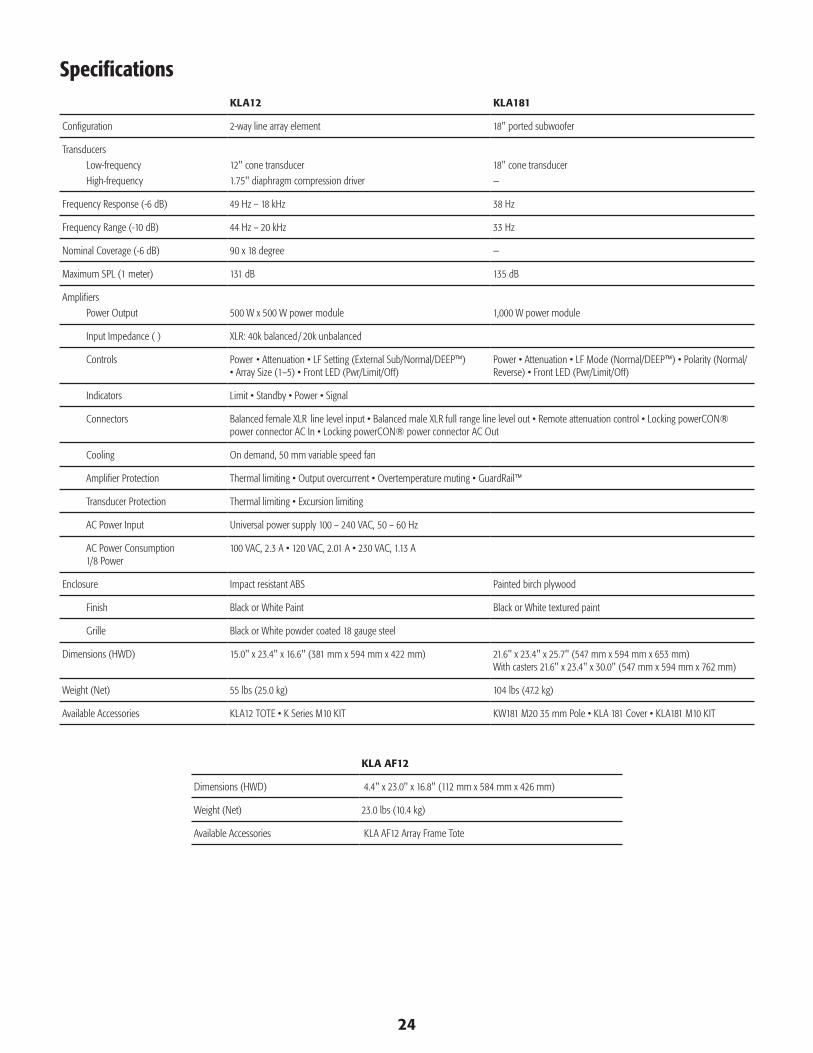
SpecificationsKLA12 KLA181
Configuration 2-way line array element 18" ported subwoofer
Transducers
Low-frequency
High-frequency
12" cone transducer
1.75" diaphragm compression driver
18" cone transducer
—
Frequency Response (-6 dB) 49 Hz – 18 kHz 38 Hz
Frequency Range (-10 dB) 44 Hz – 20 kHz 33 Hz
Nominal Coverage (-6 dB) 90 x 18 degree —
Maximum SPL (1 meter) 131 dB 135 dB
Amplifiers
Power Output 500 W x 500 W power module 1,000 W power module
Input Impedance (Ω) XLR: 40k balanced / 20k unbalanced
Controls Power•Attenuation•LFSetting(ExternalSub/Normal/DEEP™)•ArraySize(1–5)•FrontLED(Pwr/Limit/Off)
Power•Attenuation•LFMode(Normal/DEEP™)•Polarity(Normal/Reverse)•FrontLED(Pwr/Limit/Off)
Indicators Limit•Standby•Power•Signal
Connectors BalancedfemaleXLRlinelevelinput•BalancedmaleXLRfullrangelinelevelout•Remoteattenuationcontrol•LockingpowerCON®powerconnectorACIn•LockingpowerCON®powerconnectorACOut
Cooling On demand, 50 mm variable speed fan
Amplifier Protection Thermallimiting•Outputovercurrent•Overtemperaturemuting•GuardRail™
Transducer Protection Thermallimiting•Excursionlimiting
AC Power Input Universal power supply 100 – 240 VAC, 50 – 60 Hz
AC Power Consumption 1/8 Power
100VAC,2.3A•120VAC,2.01A•230VAC,1.13A
Enclosure Impact resistant ABS Painted birch plywood
Finish Black or White Paint Black or White textured paint
Grille Black or White powder coated 18 gauge steel
Dimensions (HWD) 15.0" x 23.4" x 16.6" (381 mm x 594 mm x 422 mm) 21.6" x 23.4" x 25.7" (547 mm x 594 mm x 653 mm) With casters 21.6" x 23.4" x 30.0" (547 mm x 594 mm x 762 mm)
Weight (Net) 55 lbs (25.0 kg) 104 lbs (47.2 kg)
Available Accessories KLA12TOTE•KSeriesM10KIT KW181M2035mmPole•KLA181Cover•KLA181M10KIT
KLA AF12
Dimensions (HWD) 4.4" x 23.0" x 16.8" (112 mm x 584 mm x 426 mm)
Weight (Net) 23.0 lbs (10.4 kg)
Available Accessories KLA AF12 Array Frame Tote
Mailing Address:
QSC Audio Products, LLC
1675 MacArthur Boulevard
Costa Mesa, CA 92626-1468 USA
Telephone Numbers:
Main Number: (714) 754-6175
Sales & Marketing: (714) 957-7100 or toll free (USA only) (800) 854-4079
Customer Service: (714) 957-7150 or toll free (USA only) (800) 772-2834
Facsimile Numbers:
Sales & Marketing FAX: (714) 754-6174
Customer Service FAX: (714) 754-6173
World Wide Web:
www.qscaudio.com
E-mail:
© 2011 QSC Audio Products, LLC. All rights reserved. QSC™ and the QSC logo are registered trademarks of QSC Audio Products, LLC in the U.S. Patent and Trademark office and other countries. Tilt-Direct, Intrinsic Correction, DEEP and GuardRail are all trademarks of QSC Audio Products, LLC. powerCON is a registered trademark of Neutrik.
All other trademarks are the property of their respective owners. US and Worldwide Patents pending.