laboratory tests ^^^-^-^ to design windrow revetment for
TRANSCRIPT

Laboratory Tests ^^^-^-^ to Design Windrow Revetment for Bank Protection
i
i MRD Hydraulic Laboratory Series Report No. 7
Mead Hydraulic Laboratory Mead, Nebraska
i September 1984
ii >••
US Army Corps of Engineers Missouri River Division
DISTRIBUTION STATEMENT A Approved for Public Release
Distribution Unlimited

REPORT DOCUM1MTATIOW PAGI Form Approved
OMB No. 0704-0188
1 Public reporting burden for this collection of information is estimated to arerä^11^r^7^Ii7mcluding the time for reviewing 'n^^^"^^^^^"I^- aather na and maintaining the data needed, and completing and reviewing the collection of information. Send comments regarding this burden estimate or any other«pert of this ?ol ertön of format Sn. including suggestions for reducing this burden, to Washington Headquarters Services Directorate for Information3perat,ons and Reports 1215 Jefferson Da" is Highway Suite 1204 Arlington, VA 22202-4302, and to the Office of Management and Budget, Paperwork Reduction Project (0704-0188). Washington, DC 20503.
1. AGENCY USE ONLY (Leave blank) 2. REPORT DATE r |W
3. REPORT TYPE AND DATES COVERED
4. TITLE AND SUBTITLE ^ ,
6. AUTHOR(S)
7. PERFORMING ORGANIZATION NAME(S) AND ADDRESS(ES)
9. SPONSORIMG/MONITORING AGENCY NAME(S) AND ADDRESS(ES)
C^w ö'^^ torf<> of £h^e#~f
5. FUNDING NUMBERS
8." PERFORMING ORGANIZATION REPORT NUMBER
10. SPONSORING/MONITORING AGENCY REPORT NUMBER
YY\£D Hu^aulfC/
Kepor-f A «7 11. SUPPLEMENTARY NOTES 11. SUPPLEIWfcNlAKY NUits , . , A^
12a. DISTRIBUTION/AVAILABILITY STATEMENT 12b. DISTRIBUTION CODE
13. ABSTRACT (Maximum 200 words) ABSTRACT (Maximum JUOworas) , . .
btftiWs. m^( WuAroAAUü Uihorahy. <U mead ^odi( >h^<l>tj "
4. SUBJECT TERMS , ,
u)i A drooo reife-j- ftvsn-f-
15.'NUMBER" ÖF PAGES
167 PRICE CODE
17. SECURITY CLASSIFICATION OF REPORT
18. SECURITY CLASSIFICATION OF THIS PAGE OF REPORT ur I mis KAUE W ""'""'■I ,
ie. SECüRITY'CLASSTFT'äTION OF ABSTRACT
""20."LIMITATION OF ABSTRACT
NSN 7540-01-280-5500 Standard Form 298 (Rev. 2-89) Prescribed by ANSI Std. Z39-18 298-102

1
DEPARTMENT OF THE ARMY
CORPS OF ENGINEERS
LABORATORY TESTS TO DESIGN
WINDROW REVETMENT
FOR
BANK PROTECTION
CONDUCTED AT
MEAD HYDRAULIC LABORATORY
MEAD, NEBRASKA
Project C10852 Disk No. 518-C
Draft Report No. 7
U. S. ARMY ENGINEER DISTRICT, OMAHA, NEBRASKA
ü. S. ARMY ENGINEER DISTRICT, KANSAS CITY, MISSOURI
MISSOURI RIVER DIVISION, OMAHA, NEBRASKA
TABLE OF CONTENTS
Chapter
I
II
III
IV
V
List of Tables
List of Symbols
List of Photographs
List of Plates
List of Publications
INTRODUCTION
THE MODEL
OPERATING PROCEDURES
DATA ANALYSIS
CONCLUSIONS
Page
i
ii
iv
vi
vii
1
2
7
9
15
Appendix
A Bibliography
B Windrow Shapes
C Photos
D Plates
1
LIST OF TABLES
Table Title
1 Average Model Bed Material Characteristics
2 Basin Wall Stations - Bed Material: Sand
3 Basin Wall Stations - Bed Materials: Ground Walnut Shells
4 Prototype to Model Stone Specifications
5 Average Characteristics of Model Stone
6 End Conditions - Trapezoidal Shaped Windrows
7 End Conditions - Rectangular Shaped Windrows
8 End Conditions - Triangular Shaped Windrows
9 End Conditions - Augmented Revetments
10 End Conditions - Segmented Windrows
11 End Conditions - No Windrow
12 Windrow Shape Comparisons

LIST OF SYMBOLS
b = subscript, signifies function of bank material
D = depth adjacent to eroding bank line
d = a representative particle size = d5Q
d, = representative size of bank material
d = representative size of revetment material
e = void ratio of material
G = specific gravity of material
g = acceleration produced by gravity
^0 = maximum initial height of windrow
ni = height of windrow remaining on bank
hQ - average initial height of windrow
h = average height of eroded portion of windrow
L = horizontal length along bank line
P_ = slope length of revetment
r, = radius point of the eroded edge of windrow
r« = radius point of the toe of the revetment
ro = radius point cf the top edge of the revetment, also equal to radius point of the left water's edge
Sg = slope of the energy gradient
S = revetment sample weight needed for a layer thickness of one dr
S.. = revetment sample obtained from upper portion of revetment adjacent to water line
S„ = revetment sample obtained from middle of revetment
S^ = revetment sample obtained from lower portion of revetment adjacent to toe
S^ = revetment sample consisting of all stone remaining within the one foot sample width of the revetment after samples S, , So, and So had been extracted.
ii
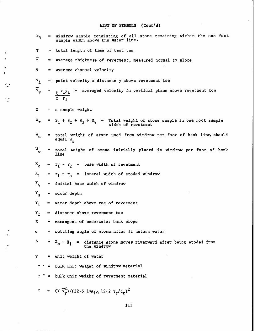
LIST OF SYMBOLS (Cont'd)
Sc = windrow sample consisting of all stone remaining within the one foot sample width above the water line.
T = total length of time of test run
t - average thickness of revetment, measured normal to slope
V = average channel velocity
v£ = point velocity a distance y above revetment toe
v = vivi = averaged velocity in vertical plane above revetment toe
TIT W = a sample weight
W S, + S2 + So + SA = Total weight of stone sample in one foot sample width of revetment
W a total weight of stone used from windrow per foot of bank line, should equal W
W = total weight of stone initially placed in windrow per foot of bank line
x0 = rl ~ r2 = Dase width of revetment
X^ = r, - r = lateral width of eroded windrow
X^ = initial base width of windrow
Yg = scour depth
Y(. = water depth above toe of revetment
y^ - distance above revetment toe
Z = cotangent of underwater bank slope
a = settling angle of stone after it enters water
A =■ XQ - Xi = distance stone moves riverward after being eroded from the windrow
Y = unit weight of water
Y ' = bulk unit weight of windrow material
Y " ■ bulk unit weight of revetment material
T - (Y Vy)/(32.6 log10 12.2 Yt/dr)2
iii

LIST OF PHOTOGRAPHS
Photo No. Caption
1. Typical bank line looking upstream in the uncontrolled portion of the Missouri River, about mile 1332, near Bismarck, ND, known as the Dry Point Area.
2. A windrow revetment near Vermillion, SD, in the Vermillion River Chute Area about Missouri River Mile 771. Note natural appearance of bank. Windrow may be seen near top of 20 foot bank. The top of the revetment is visible near the water's edge. Depth to toe of revetment is about 20 feet.
3. Windrow revetment near Fort Calhoun, Nebraska, about Missouri River Mile 639.
4. Windrow revetment near Omaha, Nebraska, about River Mile 634. Note minimal site preparation.
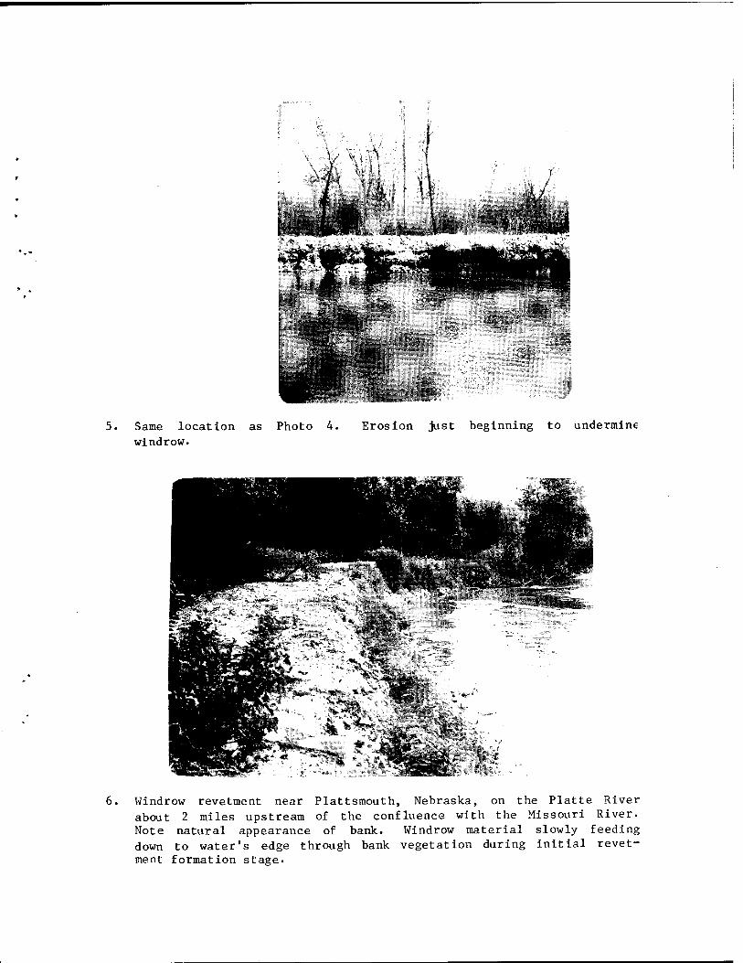
5. Same location as Photo 4. Erosion just beginning to undermine windrow.
6. Windrow revetment near Plattsmouth, Nebraska, on the Platte River about 2 miles upstream of the confluence with the Missouri River. Note natural appearance of bank. Windrow material slowly feeding down to water's edge through bank vegetation during initial revetment formation stage.
7. Reconstruction of sand bed model. Horizontal bar in midsection of photo fixed at left to center point of curve. Right end of bar free to slide along outside edge of basin. Person at right sliding end of bar while person in channel removing excess material from in front of template attached to bar.
8« Reconstructed channel prior to start of run 3. Flags were used initially to locate centerline of windrow at 1 foot intervals.
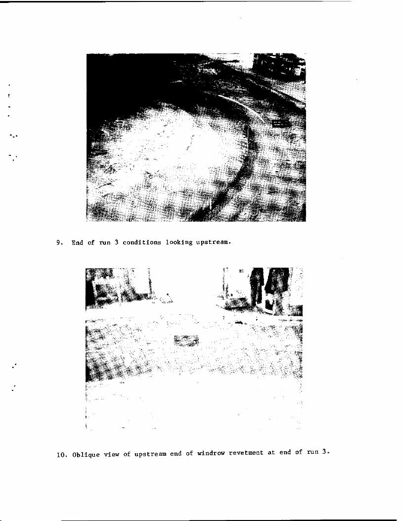
9. End of run 3 conditions looking upstream.
10. Oblique view of upstream end of windrow revetment at end of run 3.
11. Looking down on model test area at end of Run 9. Colored stone placed in windrow to observe movement of stone. Note that except for toe zone, stone moved down the slope with no downstream component.
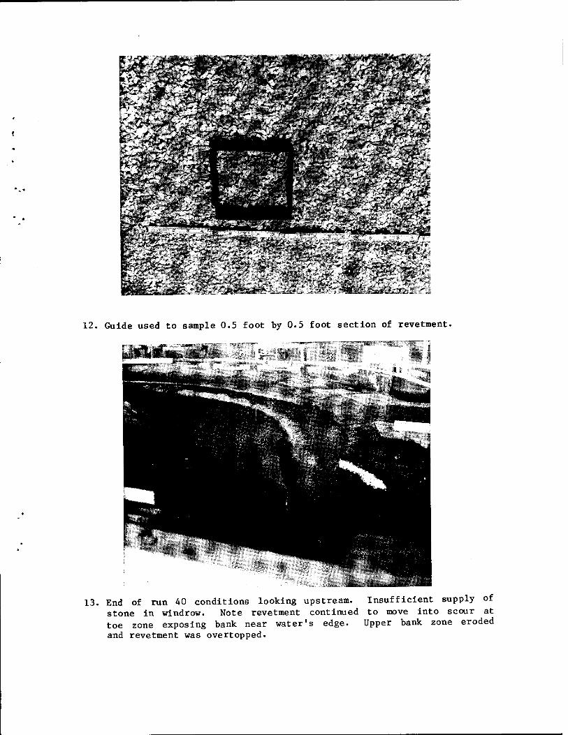
12. Guide used to sample 0.5 foot by 0.5 foot section of revetment.
13. End of run 40 conditions looking upstream. Insufficient supply of stone in windrow. Note revetment continued to move into scour at toe zone exposing bank near water's edge. Upper bank zone eroded and revetment was overtopped.
iv
LIST OF PHOTOGRAPHS (Cont'd)
Photo No. Caption
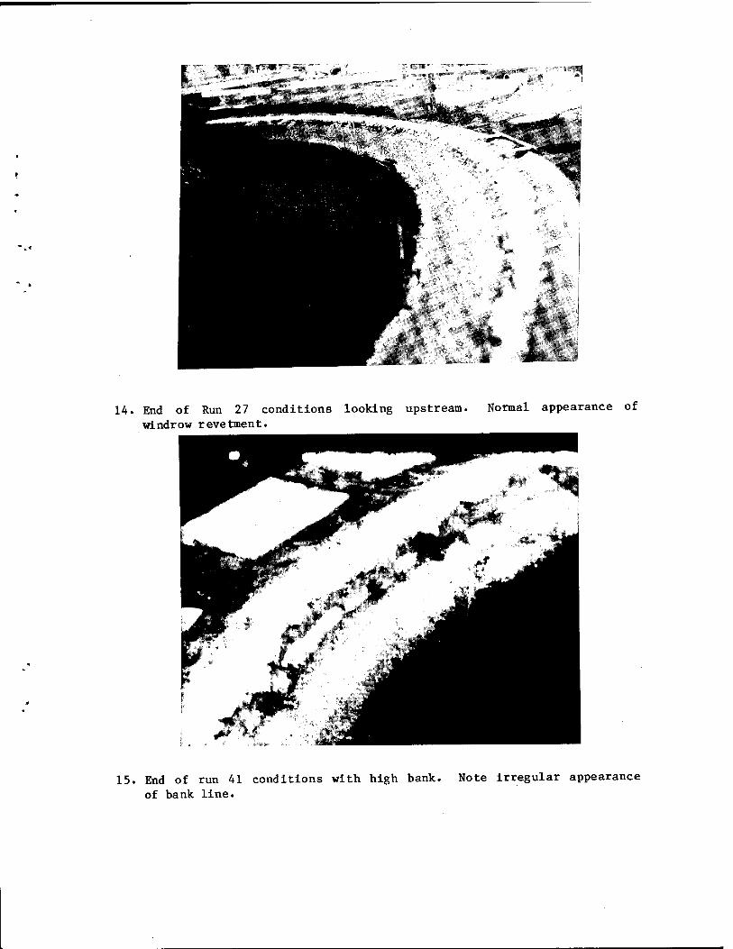
14. End of Run 27 conditions looking upstream. Normal appearance of windrow revetment.
15. End of run 41 conditions with high bank. Note irregular appearance of bank line.
16. Looking upstream during testing of segmented windrows. Note scalloped bank line.

Plate Ho.
1
2
3
4
5
6
7
8
LIST OF PLATES
Title
Windrow Definition Sketch
Model Basin - Bed Material: Sand
Model Basin - Bed Material: Ground Shells
Mechanical Analysis of Model Bed Materials and Size Limitations for Model and Prototype Rock
Revetment and Windrow Stone Sampling Technique
Isovels, Station 89.5, Run 31, Time 26 hours
Cotangent of Settling Angle vs Cotangent of Revetment Slope Angle
t/dr versus x
(y s ~ y)dr
i
vi
LIST OF PUBLICATIONS
MRD Hydraulic Laboratory Series Report No. 1, Operation and Function of the Mead Hydraulic Laboratory
MRD Hydraulic Laboratory Series Report No. 2, Laboratory Investigation of Underwater Sills on the Convex Bank of Pomeroy Bend
MRD Hydraulic Laboratory Series Report No. 3, Laboratory Investigation of Sioux City Boat Marina Entrance
MRD Hydraulic Laboratory Series Report No. 4, Laboratory Investigation of Manawa and Bellevue Bends
MRD Hydraulic Laboratory Series Report No. 5, Laboratory Investigation of Kansas River Bend and Kansas River Reach
MRD Hydraulic Laboratory Series Report No. 6, Laboratory investigation of Junction Losses at the Kansas and Missouri River Confluence
Also available for loan.
Time lapse movie of model tests without narrative for:
Report No. 7
Condensed time lapse movies summarizing laboratory investigations, with narratives for:
Report No. 1 Report No. 7
vii

I. INTRODUCTION
1. This report presents results of model studies on a windrow revetment erosion control structure. These studies were conducted at the Missouri River Division's Mead Hydraulic Laboratory. The Mead model facility was authorized to investigate problems on the Missouri River by the Chief of Engineers in his indorsement of the Missouri River Division Engineer's letter of request dated 24 April 1964.
2. This study was reviewed and guidance provided by the Technical Engineering Branch of the Division, Messrs. A. Harrison and W. Mellema; Omaha District, Mr. H. Christian and Mr. L. Horihan; Kansas City District, Mr. W. Linder and Mr. T. Burke. The tests were conducted by Omaha District personnel, Mr. R. Singleton, Mr. E. Matson, and Mr. W. Howard.
3. Prior model studies at the Mead facility have dealt with specific problem areas on the navigation portion of the Missouri River. This model study was of a general nature, and the model parameters were varied over a wide range, the purpose being to provide general design information on the windrow revetment.
4. A windrow revetment is formed when stone, which has been placed along an eroding bank line, is undercut by the stream. The stone is then displaced down the bank where it forms a protective blanket which halts further erosion. See Plate 1. As long as a sufficient quantity of stone is available from the windrow of material, the stone will pave the bank thereby armoring the bank line against further erosion. More conventional bank line revetments are constructed by:
a. Digging a trench landward of the bank line and placing a blanket of stone on the side slope of the trench. The trench must be of sufficient depth and the blanket thickness of the stone great enough, so that when the erosion process exposes the stone to the flow the revetment does not fail by undermining or leaching.
b. Placing the stone directly on the bank. With this method some of the stone may be placed on existing underwater bank slopes, thereby using a minimum quantity of stone. However, because of the irregularity of a natural bank line (see Photo 1), it may be necessary to place greater quantities of stone in the irregular areas so as to produce a uniform alignment.
5. The windrow revetment has the following advantages over the more conventional methods.
a« Complex site preparation is not required.
b. Stone may be added to or removed from the windrow as conditions dictate.
c. Manipulation of the stone is reduced.

Prototype Applications.
6. The windrow revetment concept is not new. It has been used successfully by the Bureau of Reclamation to control bank erosion along the lower Colorado River, ' and by the Omaha District Corps of Engineers on an experimental basis. See photos 2 through 6. The Bureau of Reclamation and the Omaha District have used "rule of thumb" methods to design these windrows. This model study was undertaken due to the uncertainties of "rule of thumb" methods, and a desire to have a better understanding of the parameters influencing the development of windrow revetments.
Objectives»
7. The objectives of the model tests were to determine:
a. The mechanics of the formation of the ultimate revetment shape.
b. A relationship for the minimum application rate or quantity of stone per foot of bank line required to form a stable revetment.
c. The effect of different windrow cross sections on the final shape of the r eve tment.
d. The effect of stream velocities on the final shape of the revetment.
e. The effect of stone size and gradation on the formation of the revetment.
f. The effect of bank height on revetment formation.
g. The utility of using windrows of stone to develop segmented revetments as opposed to continuous revetments.
II. THE MODEL*
Initial Consideration«
8. Since the model study was to be of a general nature, no specific river location was modeled. The guidelines used to design this model were:
a. The model should resemble a natural stream.
b. That portion of the model selected for the erosion tests must erode when not protected.
c. The geometry of the model, excluding the erosion area, should be fixed so that the flow characteristics would be consistent from run to run.
d. Visual observation of the revetment formation process would be necessary.
1 & T / Signifies reference, see Bibliography
*See reference 4 for a more thorough description of the Mead model facility.

9« Initially, in order to conform with guideline "d," it was decided that the model bed material should be a fine sand. Prior to this study finely ground walnut shells had been used for bed material in all movable bed model studies at the Mead facility, but this material is easily suspended in the flow and it was felt that this would obscure the visual observations in the study. The tests in the sand bed model were extremely time consuming; taking more than a week in some cases to complete a single run. After 13 runs the study was transferred to a duplicate model using ground walnut shells as the bed material. The revetment formation process was fairly well understood by that time so the visual observations were no longer needed. More important though was the fact that several runs per week could be made in the ground walnut shell bed material. It should be noted that the materials used to form the banks of these studies were noncohesive and the results should be interpreted accordingly.
Model Layout»
10. Each of the two models mentioned above were formed in an inclosure or basin filled with the appropriate bed material. The overall dimensions of both models were similar. See Plates 2, 3, and 4 and Tables 1, 2, and 3. Two bends of equal radii were used to form an "S" shaped model configuration. See Photos 7, 8, and 9. The "S" shaped model was selected to simulate flow characteristics encountered in natural alluvial streams.
TABLE 1
AVERAGE MODEL BED MATERIAL CHARACTERISTICS
STive "
Material Limits b
Inches
Specific
Gravity
Sand #100 < db < #8 .0020 2.65
Walnut Shells #140 < db < #30 .00094 1-31
A radius of curvature was selected to ensure that the model banks would erode. The average range of the ratios of the radii of curvature to the channel widths for bends with active erosion varies from 2.5 to 3.0.—' Considering this type of bend and the space available, the model bends were constructed with a radius of 14.5 feet and a channel width of 5 feet. The bank lines in the upper bend and the right bank of the lower bend were armored to maintain a fixed channel geometry. The left bank in the lower bend was not fixed and was permitted to erode. This erodible section of the model was used to test the windrow erosion control method.

TABLK 2
BASIN WALL STATIONS BED MATERIAL: SAND
Wall Section feet
Station Radians
Remarks
17.4R* 30.4R 41.OR 20.7 28.2 31.3 32.0 37.0 38.7 40.7 42.0 43.2 44.0 45.2 45.7 47.0 47.7 49.3 52.0 52.7 54.7 55.4 57.0 59.2 59.7 61.5 61.7 62.0 65.0 66.7 67.0 67.6 68.7 72.0 72.9 73.7 75.7 80.0
-0.882 -0.259 0.0 0.0 0.228 0.346 0.373 0.590 0.668 0.760 0.820 0.874 0.910 0.971 0.986 1.044 1.076 1.149 1.272 1.304 1.400 1.433 1.506 1.596 1.629 1.716 1.725 1.738 1.874 1.951 1.964 1.990 2.039 2.190 2.221 2.267 2.358 2.534
Tube #3 Tube #4 Tangent P3 to P2 Tangent P2 to P3 End of Kicker Tube #5 Cross Section Cross Section Cross Section ** Cross Section ** Cross Section
Tube #6 Cross Section ** Cross Section Cross Section **
Cross Section Cross Section ** Cross Section **
Cross Section Tube #7 Cross Section **
Cross Section ** Cross Section
Cross Section Cross Section
Cross Section ** Cross Section Tube #8 Cross Section ** Cross Section ** Tube #9
*R designates stations along right wall—all other stations along left wall. See Plate 2.
**Special cross sections for noncontinuous revetment tests

TABLE 3
BASIN WALL STATIONS BED MATERIAL: GROUND WALNUT SHELLS
Wall Station Feet"
Station Radians
Remarks
60 .8 R* 62 .8 R 73 .9 R 85 .0 R 58 .5 68 3 70 .0 I* 71. 2 78 .0 I 85. 0 87 .0 92. 0 I 99 .0 I
101. 1 I 106 .0 I
-0.981 -0.874 -0.336 0.0 0.0 0.228 0.295 0.319 0.552 0.874 0.964 1.182 1.510 1.609 1.832
Tube #3
Tube #4 Tangent P3 to P2 Tangent P2 to P3 End of Kicker X - Section
Tube #5 X - Section X - Section Tube #6 X - Section X - Section Tube #7 X - Section
*R Designates stations along right wall—all other stations along left wall.
*I Designates stations along inside wall parallel to bend.
See Plate 3.
Sediment Recirculation.
11. A settling basin was constructed in the sand bed model between the end of the model and the recirculation pump. A specially designed suction device, utilizing the Venturi principle, was placed in the settling basin to recirculate the sand transported out of the model and deposited in the settling basin. This recirculation device used a specially designed 3/4-inch diameter pipe "T" fitting. High velocity waterflow in the "through" portion of the "T" produced a low pressure in the stem of the "T." This low pressure sucked sand from the settling basin and transported it through a 3/4-inch diameter hose to the upper end of the model. No settling basin was required when ground walnut shells were used for the bed material as the ground walnut shells are nonabrasive and were recirculated through the pump along with the water.
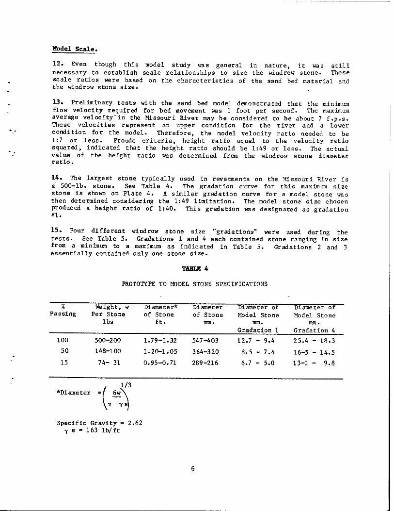
Model Scale.
12. Even though this model study was general in nature, it was still necessary to establish scale relationships to size the windrow stone. These scale ratios were based on the characteristics of the sand bed material and the windrow stone size.
13. Preliminary tests with the sand bed model demonstrated that the minimum flow velocity required for bed movement was 1 foot per second. The maximum average velocity'in the Missouri River may be considered to be about 7 f.p.s. These velocities represent an upper condition for the river and a lower condition for the model. Therefore, the model velocity ratio needed to be 1:7 or less. Froude criteria, height ratio equal to the velocity ratio squared, indicated that the height ratio should be 1:49 or less. The actual value of the height ratio was determined from the windrow stone diameter ratio.
14. The largest stone typically used in revetments on the Missouri River is a 500-lb. stone. See Table 4. The gradation curve for thi-s maximum size stone is shown on Plate 4. A similar gradation curve for a model stone was then determined considering the 1:49 limitation. The model stone size chosen produced a height ratio of 1:40. This gradation was designated as gradation if L •
15. Four different windrow stone size "gradations" were used during the tests. See Table 5. Gradations 1 and 4 each contained stone ranging in size from a minimum to a maximum as indicated in Table 5. Gradations 2 and 3 essentially contained only one stone size.
TABLE 4
PROTOTYPE TO MODEL STONE SPECIFICATIONS
% Passing
Weight, w Per Stone
lbs
Diameter* of Stone
ft.
Diameter of Stone
mm.
Diameter of Model Stone
mm. Gradation 1
Diameter of Model Stone
mm. Gradation 4
100 500-200 1.79-1 .32 547-403 12.7 - 9.4 25.4 - 18.3
50 148-100 1.20-1 .05 364-320 8.5 - 7.4 16-5 - 14.5
15 74- 31 0.95-0 .71 289-216 6.7 - 5.0 13-1 - 9.8
/ N1/3 *Diameter =/ 6w
Specific Gravity = 2.62 Y s = 163 lb/ft
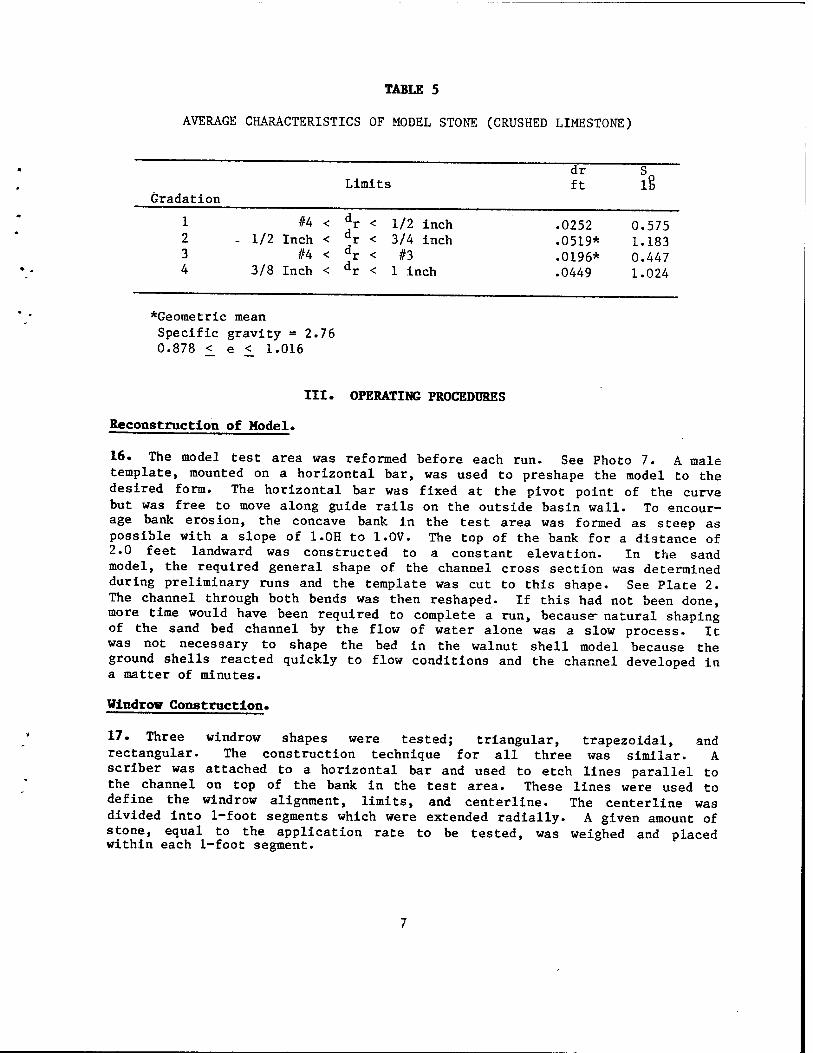
TABLE 5
AVERAGE CHARACTERISTICS OF MODEL STONE (CRUSHED LIMESTONE)
Limits Gradation
1 2 3 4
#4 < dr < 1/2 Inch < dr <
#4 < dr < 3/8 Inch < dr <
1/2 inch 3/4 inch #3
1 inch
*Geometric mean Specific gravity =2.76 0.878 < e < 1.016
dr ft h
.0252 0.575
.0519* 1.183
.0196* 0.447
.0449 1.024
III. OPERATING PROCEDURES
Reconstruction of Model«
16. The model test area was reformed before each run. See Photo 7. A male template, mounted on a horizontal bar, was used to preshape the model to the desired form. The horizontal bar was fixed at the pivot point of the curve but was free to move along guide rails on the outside basin wall. To encour- age bank erosion, the concave bank in the test area was formed as steep as possible with a slope of 1.0H to 1.0V. The top of the bank for a distance of 2.0 feet landward was constructed to a constant elevation. In the sand model, the required general shape of the channel cross section was determined during preliminary runs and the template was cut to this shape. See Plate 2. The channel through both bends was then reshaped. If this had not been done, more time would have been required to complete a run, because- natural shaping of the sand bed channel by the flow of water alone was a slow process. It was not necessary to shape the bed in the walnut shell model because the ground shells reacted quickly to flow conditions and the channel developed in a matter of minutes.
Windrow Construction.
17. Three windrow shapes were tested; triangular, trapezoidal, and rectangular. The construction technique for all three was similar. A scriber was attached to a horizontal bar and used to etch lines parallel to the channel on top of the bank in the test area. These lines were used to define the windrow alignment, limits, and centerline. The centerline was divided into 1-foot segments which were extended radially. A given amount of stone, equal to the application rate to be tested, was weighed and placed within each 1-foot segment.
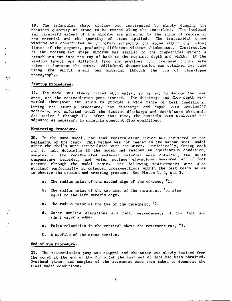
18. The triangular shape windrow was constructed by simply dumping the required quantity of stone to be tested along the centerline. The landward and riverward extent of the windrow was governed by the angle of repose of the material and the quantity of stone applied. The trapezoidal shape windrow was constructed by uniformly spreading the stone within the 1-foot limits of the segment, producing different windrow thicknesses. Construction of the rectangular shape windrow was similar to the trapezoidal except a trench' was cut into the top of bank to the required depth and width. If the windrow layout was different from any previous run, overhead photos were taken to document the setup. Additional documentation was obtained for runs using the walnut shell bed material through the use of time-lapse photography.
Startup Procedures.
19. The model was slowly filled with water, so as not to damage the test area, and the recirculation pump started. The discharge and flow depth were varied throughout the study to provide a wide range of test conditions. During the startup procedure, the discharge and depth were constantly monitored and adjusted until the desired discharge and depth "were obtained. See Tables 6 through 11. After that time, the controls were monitored and adjusted as necessary to maintain constant flow conditions.
Monitoring Procedure.
20. In the sand model, the sand recirculation device was activated at the beginning of the test. This method was not needed in the walnut shell model since the shells were recirculated with the water. Periodically, during each run to help determine if the model had reached an equilibrium condition, samples of the recirculated sediment material were obtained, the water temperature recorded, and water surface elevations measured at 10-foot centers through the model basin. The following measurements were also obtained periodically at selected cross-sections within the test reach so as to observe the erosion and armoring process. See Plates 1, 2, and 3.
a. The radius point of the eroded edge of the windrow, 1.
b. The radius point of the top edge of the revetment, r3, also equal to the left water's edge.
c. The radius point of the toe of the revetment, r2.
d. Water surface elevations and radii measurements at the left and right water's edge.
e. Point velocities in the vertical above the revetment toe, vi.
f. A profile of the cross section.
End of Run Procedure.
21. The recirculation pump was stopped and the water was slowly drained from the model at the end of the run after the last set of data had been obtained. Overhead photos and samples of the revetment were then taken to document the final model conditions.
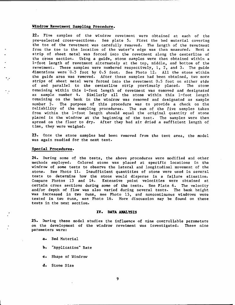
Windrow Revetment Sampling Precedure.
22. Five samples of the windrow revetment were obtained at each of the pre-selected cross-sections. See plate 5. First the bed material covering the toe of the revetment was carefully removed. The length of the revetment from the toe to the location of the water's edge was then measured. Next a strip of sheet metal was forced into the revetment along the centerline of the cross section. Using a guide, stone samples were then obtained within a 1-foot length of revetment alternately at the top, middle, and bottom of the revetment. These samples were numbered respectively, 1, 2, and 3. The guide dimensions were "0.5 foot by 0.5 foot. See Photo 12. All the stone within the guide area was removed. After these samples had been obtained, two more strips of sheet metal were forced into the revetment 0.5 foot on either side of and parallel to the centerline strip previously placed. The stone remaining within this 1-foot length of revetment was removed and designated as sample number 4. Similarly all the stone within this 1-foot length remaining on the bank in the windrow was removed and designated as sample number 5. The purpose of this procedure was to provide a check on the reliability of the sampling procedures. The sum of the five samples taken from within the 1-foot length should equal the original quantity of stone placed in the windrow at the beginning of the test. The samples were then spread on the floor to dry. After they had air dried a sufficient length of time, they were weighed.
23. Once the stone samples had been removed from the test area, the model was again readied for the next test.
Special Procedures.
24. During some of the tests, the above procedures were modified and other methods employed. Colored stone was placed at specific locations in the windrow of some tests to observe the lateral and longitudinal movement of the stone. See Photo 11. Insufficient quantities of stone were used in several tests to determine how the stone would disperse in a failure situation. Compare Photos 13 and 14. Extensive point velocities were obtained at certain cross sections during some of the tests. See Plate 6. The velocity and/or depth of flow was also varied during several tests. The bank height was increased in two runs, see Photo 15, and noncontinuous windrows were tested in two runs, see Photo 16. More discussion may be found on these tests in the next section.
IV. DATA ANALYSIS
25. During these model studies the influence of nine controllable parameters on the development of the windrow revetment was investigated. These nine parameters were:
a. Bed Material
b. "Application" Rate
c. Shape of Windrow
d. Stone Size
e. Gradation of the stone material
f. Velocity of flow
g. Average depth of flow
h. Bank height
i. Continuity of windrow
26. The end of "run data from each test are presented in Tables 6, 7, 8, 9, 10, and 11. These data represent average reach values and were obtained by averaging the information obtained at each of the cross section stations between radian stations 0.552 and 1.951. See Tables 2 and 3, and Plates 2 and 3. Data upstream of radian station 0.552 were excluded because it was determined they were influenced by the stream crossing. Similarly, data downstream of radian station 1.951 were dropped because it was determined they were influenced by exit conditions. Each table contains lists of data for a specific windrow shape. Within each table the data are subdivided into two groups, runs in the sand bed model, and runs in the walnut shell bed model.
Formation Process of Windrow Revetment.
27. The first objective of this study was to obtain an understanding of the windrow revetment formation process. The tests in the sand bed model were the basis for this understanding; however, it should be noted that the same processes were observed in the walnut shell bed model and have been documented by time lapse photography.
28. As a result of the erosion process, the stone in the windrow is under- mined and drops onto the underwater bank slope. If there is sufficient momentum and if the underwater bank slope is steep enough, the stone may slide or roll some distance down the underwater bank slope. Therefore, the underwater bank slope is highly significant. Measurements on the model bank slopes taken at different times during the course of each test tend to indi- cate that the underwater bank slope flattens slightly as the revetment stabilizes. See Tables 6, 7, 8, and 10.
29. As the first quantity of stone moves down the underwater bank slope, the bank line is again subject to erosion. Additional bank erosion drops more stone into the stream. It is important to note that the stone, after it falls onto the underwater bank, does not disperse but remains clustered. Turbulence around individual stones causes the underwater bank material to scour. Since the stone remains clustered, most of this scour occurs at the leading edge (toe) of the partially formed revetment. The scour eventually produces an unstable condition and the stone slides or rolls down the bank slope into the scoured area. After a time, an equilibrium condition is reached with the bed material at the toe of the revetment whereby the amount of bed material being scoured equals the amount deposited from upstream and the revetment stabilizes. The depth and velocity adjacent to the bank will increase as the windrow revetment forms because there will be no bank material sloughing into and supplying sediment to the bed, and because the reveted bank will be more uniform and will offer less resistance to the flow
10
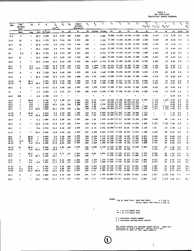
TABLE 6 END CONDITIONS
TRAPEZOIDAL SHAPED WINDROWS
tun Tine
Between
Runs
AT T Q S. do"*)
PT *T Vater
Surface
Elevation
Tt V y
V rl r2 r3 X
(r3-r2)
Xl
o> <W X4
W V V
(w /: w
daya hri hri ft3/aec ft ft ft ft ft/aec ft/iec ft ft ft ft ft ft ft ft lb/ft lb/
9-5 2 36.7 2.400 13.5 6.55 .345 0.605 .661 - 1.080 16.860 17.000 16.050 17.300 1.250 0.140 1.11 0.58 6.0 10.
11-6 10 - 25.6 1.170 12.1 5.64 .169 0.592 .390 - 1.230 17.180 17.440 16.200 17.260 1.060 0.260 .80 0..32 2.0 6.
18-3 18 - 20.0 0.570 8.0 5.95 .150 1.264 .400 - 0.640 17.200 17.650 16.700 17.592 0.892 0.450 .44 0.40 1.5 3.
19-2 1 - 19.3 0.645 5.6 5.74 .181 1.323 .470 - 0.623 17.100 17.412 16.333 17.371 1.037 0.312 .72 0.60 3.0 5.
20 0.2 - 18.4 0.570 6.8 5.95 .189 1.325 .440 - 0.512 17.150 17.533 16.425 17.508 1.083 0.383 .70 0.50 2.0 4.
24-3 11 - 13.0 0.841 8.7 6.05 .139 1.322 .482 - 1.000 17.100 17.612 16.250 17.508 1.258 0.512 .75 0.60 3.0 5.
25-3 6 - 25.2 0.448 10.4 5.63 .168 1.331 .386 0.81* 0.475 17.100 17.387 16.487 17.221 0.733 0.287 .45 0.60 3.0 5.
26-1
26-2
4 4.1
6.5 10.6
1.030
1.260
21.8
16.6
5.58
6.17
.146
.174
1.275
1.356
.404
.412
1.39**
1.08**
1.320
1.170
16.914 17.450
16.914 17.619
16.283
16.400
17.346
17.581
1.062
1.181
0.536 .53
0.705 .48
0.97
0.97 4.5
4.5
4.
4.
27-3 6 - 9.6 1.550 16.4 5.63 .193 1.333 .502 1.46 1.430 17.080 17.450 16.072 17.283 1.212 0.370 .84 0.65 6.0 9.
31-2 4 30.2 0.966 10.4 5:73 .196 1.360 .470.. 1.03 0.861 17,080 17.392 16.304 17.396 1.042 0.312 .73 0.65 6.0 9.
32-01
32-12
16 25.1 24.3 49.4
0.576
1.540
10.0 12.8
5.56 5.64
.186
.199
1.360
1.340
.449
.453
0.78
1.38
0.558
1.390
17.080 17.237
17.080 17.492
16.212
16.175
17.067
17.325
0.854
1.150
0.157 .70
0.412 .74
0.65
0.65
6.0
6.0
9.
9.
39-1 3 - 4.2 0.712 11.2 5.90 .132 1.357 .470 1.07* 0.918 17.200 17.521 16.550 17.504 0.954 0.321 .63 0.40 2.0 5.
10 .3 - 3.7 0.602 7.0 5.91 .173 1.362 .380 0.81* 0.590 17.300 17.550 16.592 17.542 0.950 0.250 .70 0.20 1.0 5.
42-0 238 - 6.0 0.700 9.3 - - - - - - - - - - - - 0.66 6.0 9.
43-0
13-1
43-2
43-3
43-«
1 18.8
3.4
2.0
3.2
2.2 29.6
0.700
1.320
1.820
2.860
3.980
8.7
10.4
33.1
5.68
5.54
5.81
.191
.218
.246
1.365
1.366
1.35«
1.382
.563
.652
.597
.696
.709
0.76
0.86
1.35
1.80
2.05
0.647
1.530
2.830
16.950
16.950
16.950
16.950
16.950
17.258
,17.49]
,17.39]
,17.57J
17.57]
16.200
16.110
16.150
16.020
16.080
17.133
[17.20]
L17.17J
17.260
17.450
0.937
1.233
1.367
.31
.54'
.44
•«. .62.
[.63]
f:#
0.90
0.90
0.90
0.90
0.90
9.0
9.0
9.0
9.0
9.0
10.
10.
10.
10.
10.
44-01
44-12
5 22.8
2.4 25.2
0.913
2.860
9.6
4.4
5.43
5.72
.205
.226
1.363
1.379 .622
.594 ,
0.97
1.95
0.833
2.240
16.550 [17.08]
16.550 L17.51]
15.780
15.840
16.960
17.390
1.175
1.550 - - 1.70
1.70
9.0
9.0
5.
5.
46-3 1 - 4.1 1.880 12.9 5-80 .195 1.363 .566 1.66 1.670 16.900 [l7.5lJ 16.300 17.380 . 1.083 3.608 .48 1.00 9.0 9.'
48-3 2 - 13.9 0.703 11.8 5.47 .156 1.346 .456 0.90 0.831 16.500 El7.17] 15.830 17.050 1.220 .67] [.55] 1.80 4.8 2.
49-3 1 - 8.4 0.703 11.4 6.24 .153' 1.348 .375 0.73 0.742 16.900 [l7.94] 16.66 17.820 1.170 1.04 .13 1.00. 1.1 1.:
41-1 1 - 20.4 0.584 16.8 5.59 .121 1.363 .397 0.83* 0.866 17.076 17.258 15.967 17.075 1.108 0.182 .93 0.65 6.0 9.:
36-1 36-4
36-11
36-21
2
0.2 1
23.0 29.8
20.1
4.5 77.4
0.829 1.200
0.469
1.590
7.0
3.2
11.1
17.5
5.89
5.90
3.51 6.34
.199
.171
.148
.184
1.370
1.357
.1.225
1.363
.550
.510
.370
.460
0.95*
1.19*
1.11*
1.42*
0.715
1.210
0.922
1.390
17.100 17.400
17.100 17.475
17.100 17.396
17.100 17.492
16.267
16.433
16.417
16.333
17.237
17.300
17.075 17.392
0.971 0.300
0.867 0.375
0.658 0.296
1.058 0.392
.67
.49
.36
.67
0.60
0.60
0.60
0.60
4.0
4.0
4.0
4.0
6."
6.
6.; 6.7
33-12
33-13
76 30.8
3.6 34.4
0.409
1.220
6.3
23.9
5.66 .100 1.350 .320
.370
0.89* 0.730 17.150 17.583
17.150 18.167
16.517
16.350
17.458 0.942 0.433
1.016 .51 1.00
1.00
6.0
6.0
6.C
6.1
34-2
34-3 7 25.3
1.4 26.7
0.708
1.150
7.8
10.1
5.77 .144 1.360
1.360
.430
.480
0.86 0.861 17.150 17.450 17.150 17.888
16.217
16.625
17.342
17.688
1.125 0.300
1.117 0.738
.82
.38
1.00
1.00
6.0
6.0
6.t
6.1
35-2
35-3 5 5.4
3.4 8.8 1.140
1.820
15.1
31.2
6.14
5.78
.150
.172
1.360
1.360
.490
.550
1.33*
1.61*
1.250
1.690
17.020 17.492
17.020 17.596 16.333
16.300 17.379 17.542
1.046 C
1.242 C
.472
.576 .57
.67
0.76
0.76 9.0 9.0
11. f
3? 01 37-12
17-25
3
0.2
0.2
17.6
17.9 25.3 60.8
0.743 1.070
1.780
7.4
7.7
10.1
5.74
5.86 6.04
.184
.197
.214
1.353
1.359 1.377
.520
.480
.600
0.95* 0.84*
1.45
0.708
0.930 1.380
17.150 17.437
17.150 17.500 17.150 17.762
16.317
16.317
16.400
17.325
17.425 17.617
1.008 l
1.108 C
1.217 C
.287
.350
.612
.72
.76
.61
0.50
0.50
0.75
8.0
8.0
12.0
16. C 16.r
16. C
51-1 3 - 1.0 1.200 16.8 5.70 .164 1.356 .554 1.27 1.290 16.900 [17.54] 16.220 17.420 1.210 | .64] [-57] 1.00 7.3 7.3
52-2 1 - 18.4 1.200 21.7 5.73 .170 1.345 .521 1.15 1.240 16,900 | 17.43] 16.040 17.31 1.270 [.53] [-74] 1.00 14.7 14.7
Top of Bank Elev: Sind Bed Model - 1.200 ft Walnut Shall Bed Model- 1.500 ft
v at 0.6 depth only v at 0.8 depth only
( ) indicates aingle lample [ ] indicates extrapolated values
All other values are average reach values. Sand bed indicated by solid symbols. Walnut shell bed indicated by open or half open symbols.
©

TABLE 6 3 CONDITIONS DAL SHAPED WINDROWS
D 0 1
1>„Y'
«W Shape hy hf hr'
(Xjhf') <w e
Change
ft ft lb/ft lb/ft' lb/ft" lb lb lb lb
0 l.ii 0.58 6.0 10.3 ■ 1.00 10.3 1.45 1.9 0 0.732 0.413 0.351 1.014 2.51 2.891 5.40 9-5
•0 .80 0.32 2.0 6.2 ■ 1.00 6.2 1.62 2.7 29 0.290' 0.275 0.224 0.374 1.16 0.794 1.96 11-6
0 .44 0.40 1.5 3.8 : 1.00 3.8 1.50 2.2 - 0.420 0.394 0.394 0.330 1.54 0.092 1.63 18-3
2 .72 0.60 3.0 5.0 z 1.00 5.0 1.56 2.2 57 0.373 0.420 0.368 0.585 1.75 1.237 2.98 19-2
3 .70 0.50 2.0 4.0 c 1.00 4.0 1.53 2.5 - 0.410 0.458 0.398 0.674 1.94 0.217 2.16 20
2 .75 0.60 3.0 5.0 r 1.00 5.0 2.56 2.6 - 0.445 0.534 0.577 1.200 2.76 0.732 3.49 24-3
7 .45 0.60 3.0 5.0 : 1.00 5.0 1.44 1.9 - 0.421 - - - - - Equipment Halfunction-void 25-3
6 5
.53
.48 0.97 0.97
4.5 4.5
4.6 4.6 E 1.00
1.00 4.6 4.6
2.49 2.6 3.27 2.9 12
0.569 0.637; 0.691 0.583 2.303 4.21 0.981 5.20 Changed Velocity
26-1 26-2
0 .84 0.65 6.0 9.2 ; 1.00 9.2 3.42 2.4 9 0.699 0.733 0.621 1.378 3.43 2.458 5.89 27-3
2 .73 0.65 6.0 9.2 : 1.00 9.2 2.88 2.2 5 0.622 0.544 0.571 1.148 2.88 - - 31-2
7 2
.70
.74 0.65 0.65
6.0 6.0
9.2 9.2
; 1.00 1.00
9.2 9.2
1.4. 3.8C
1.9 2.5 32
0.455* 0.520 0.740 0.689
0.505 0.655
0.601 1.831
2.08 3.92 1.506 5.82 Changed Velocity
32-01 32-12
I .63 0.40 2.0 5.0 r 1.00 5.0 1.6C 2.0 - 0.551 0.489 0.456 0.504 2.00 0 2.00 Insufficient Supply to point of failure 39-1
0 .70 0.20
0.66
1.0
6.0
5.0
9.1 - 1.00
1.00
5.0
9.1
l.OC 2.5
_ - i 0.352
_ _ . _ _ Failed-Insufficient Supply Failed
40
42-0
] [-63]
[■«] 1.75J
0.90 0.90 0.90 0.90 0.90
9.0 9.0 9.0 9.0 9.0
10.0 10.0 10.0 10.0 10.0
n
1.00 1.00 1.00 1.00 1.00
10.0 10.0 10.0 10.0 10.0
!3. X. ,5.4. ,4.4. ,6.2. 6.2.
1.7
1.8 1.9
6 12 0.663| 0.722
1 0.907 6.844 9.14 0 9.14
Changed Velocity Changed Velocity Changed Velocity Changed Velocity
43-0 43-1 43-2 43-3 43-4
- 1.70 1.70
9.0 9.0
5.3 5.3
D p.
1.00 1.00
5.3 5.3 -
1.9 2.6 37
1 - - -
- - Changed Velocity 44-01 44-12
1 .48 1.00 9.0 9.0 D 1.00 9.0 5.47 1.9 -10 1.033 ; 1.460 0.792 2.734 6.02 - - "46.3
[.55] 1.80 4.8 2.7 L. 1.00 2,7 1.8] 2.7 12 0.388 1 0.407 j
0.454 0.683 1.93 3.022 4.95 .Changed Velocity 48-3
.13 1.00. 1.1 1.1 C 1.00 1.1 1.1] 3.1 11 0.257 i 0.261 ! 0.319 0.596 1.43 0.507 1.94 Void-Data Error 49-3
:
.93
.67
.49
.36
.67
0.65
0.60 0.60 0.60 0.60
6.0
4.0 4.0 4.0 4.0
9.2
6.7 6.7 6.7 6.7
c
c t I t
1.00
1.00 1.00 1.00 1.00
9.2
6.7 6.7 6.7 6.7
1.68
2.00 2.50 1.97 2.61
2.8
1.8 1.7 1.8 2.3
-6 0
28
0.557 I 0.596 |
0.444 0.421 0.491 ! 0.509 0.431 i0.460 0.474 (0.501
0.593
0.451 0.517 0.527 0.524
1.074
0.606 1.160 0.885 1.165
2.82
1.92 2.66 2.30 2.66
- -
High tank El.- 1.850 ft
Changed Velocity Changed Velocity Changed Velocity
41-1
36-1 36-4 36-11 36-21
.51 1.00 1.00
6.0 6.0
6.0 6.0 3
1.00 1.00
6.0 6.0
2.60 6.00
2.9 -
I 0.692 1 0.726 0.722 0.860 3.00
- - Changed Velocity Failed by leaching
33-12 33-13
.82
.38 1.00 1.00
6.0 6.0
6.0 6.0
3 3
1.00 1.00
6.0 6.0
1.80 4.43
2.6 0 0.660 i0.604 0.926 i 1.074
0.839 1.252
1.390 1.643
3.4.9 4.89
0 3.49 Changed Velocity Failed by leaching
34-2 34-3
.57
.67 0.76 0.76
9.0 9.0
11.8 11.8
3 3
1.00 1.00
11.8 11.8
5.59 6.82
2.1 2.3 10 1.083 j 1.321 1.515 3.617 7.54
- - Changed Velocity
35-2 35-3
■ .72 .76 .61
0.50 0.50 0.75
8.0 8.0 12.0
16.0 16.0 16.0
3 3 3
1.00 1.00 1.00
16.0 16.0 16.0
4.59 5.60 9.79
1.9 2.3 2.0
21 5
1.070 ,1.200 1.092 j1.195 1.323 1.455
1.046 1.189 1.735
1.767 2.212 5.318
5.08 5.69 9.83
- - Changed Velocity Changed Velocity
37-01 37-12 37-25
[-57] 1.00 7.3 7.3 a 1.00 7.3 [ 4.7] 2.2 - 0.708 10.829 0.741 2.730 5.01 1.405 6.41 51-1
[-74] 1.00 14.7 14.7 3 1.00 14.7 [ 7.8] 2.4 4 1.358 1.528 1.238 4.644 8.77 5.155 13.92 52-2
- 1.200 ft el- 1.500 ft
es. Sand bed 11 bed
WINDROW SHAPE
ROCK GRADATION
* * a B a
■w tr A A * 4
TRAPEZOIDAL TRAPEZOIDAL WITH OAPSCSEOMENTEDJ
TRAPEZOIDAL TRAPEZOIDAL TRAPEZOIDAL RECTANGULAR TRIANCULAR
TRIANGULAR WITH GAPSCSEGMENTEDJ
TRIANGULAR WITH 2ND WINDROW PLACED AFTER 1ST DEPLETED (S)
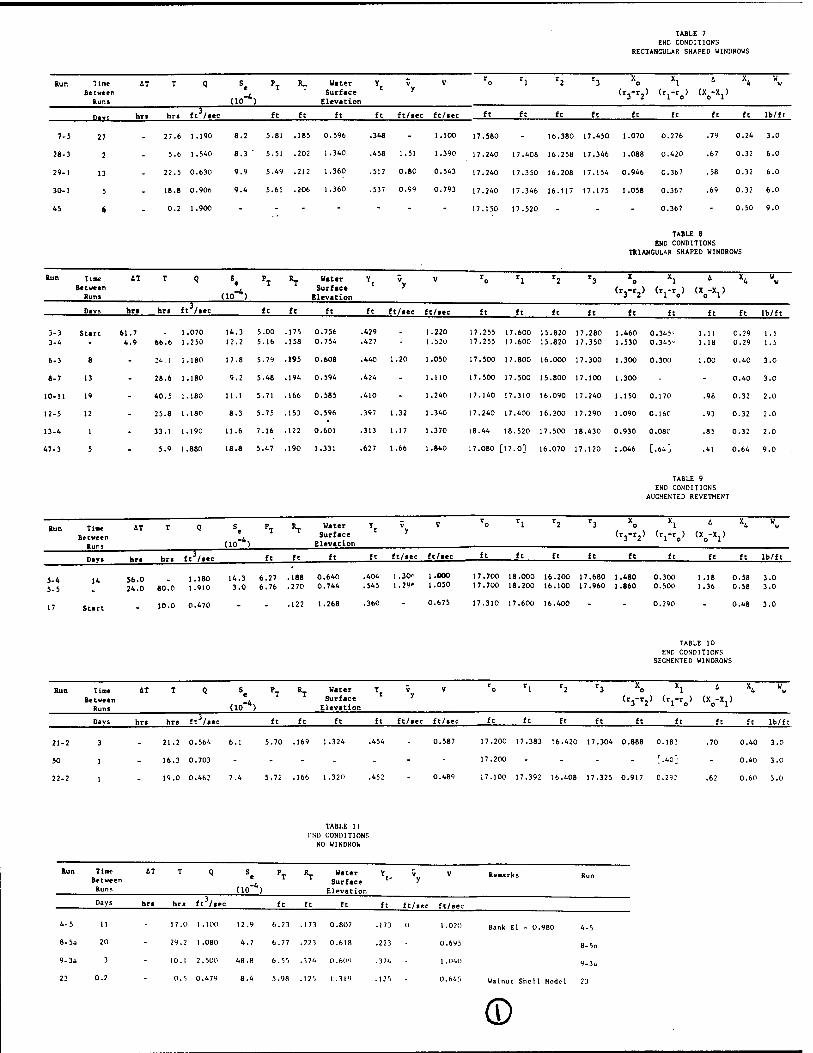
TABLE 7 END CONDITIONS
RECTANGULAR SHAPED WINDROWS
Run Time AT T Q S P_ R_ Water Y v V 0 1 2 '3 o 1 Between . Surface ' (r,-r.) (r,-r ) (X -X.)
Runs (10 ) Elevation 3 2 1 o o 1
p.vs hrt hr« ft /aec ft ft ft ft ft/iec ft/ite ft ft ft ft ft ft ft ft lb/ft
7-5 27 - 27.6 1.190 8.2 5.81 .185 0.596 .348 - 1.100 17.580 - 16.380 17.450 1.070 0.276 .79 0.24 3.0
28-3 2 - 5.6 1.540 8.3' 5.51 .202 1.340 .458 1.51 1.390 17.240 17.408 16.258 17.346 1.088 0.420 .67 0.32 6.0
29-1 13 - 22.5 0.630 9.9 5.49 .212 1.360 .512 0.80 0.543 17.240 17.350 16.208 17.154 0.946 0.367 .58 0.32 6.0
30-1 5 - 18.8 0.906 9.4 5.61 .206 1.360 .537 0.99 0.793 17.240 17.346 16.117 17.175 1.058 0.367 .69 0.32 6.0
45 6 - 0.2 1.900 ... - ... 17.150 17.520 ... 0.367 - 0.50 9.0
TABLE 8 END CONDITIONS
TRIANGULAR SHAPED WINDROWS
*>"> Time 41 T Q S« PT "T W"" Y v V ro rl r2 r3 X» Xl 4 Between ,
Rum (10 ) Elevation Surface y <r,-r.) (r.-r ) (X -X.) Ilevation 3 2 1 ° o 1
Day» hr» hn ft /iee ft ft ft ft ft/iec ft/iec ft ft ft ft ft ft ft ft lb/ft
3-3 Start 61.7 - 1.070 14.3 5.00 .175 0.756 .429 - 1.220 17.255 17.600 15.820 17.280 1.460 0.345" l.n 0.29 1.5 3-4 - 4.9 66.6 1.250 12.2 5.16 .158 0.754 .427 . 1.520 17.255 17.600 15.820 17.350 1.530 0.345= 1.18 0.29 1.5
6-3 8 - 24.1 1.180 17.8 5.79 .195 0.608 .440 1.20 1.050 17.500 17.800 16.000 17.300 1.300 0.300 1.00 0.40 3.0
8-7 13 - 28.6 1.180 9.2 5.48 .194 0.594 .424 - 1.110 17.500 17.500 15.800 17.100 1.300 - - 0.40 3.0
10-11 19 - 40.5 1.180 11.1 5.71 .166 0.585 .410 - 1.240 17.140 17.310 16.090 17.240 1.150 0.170 .98 0.32 2.0
12-5 12 - 25.8 1.180 8.3 5.75 .153 0.596 .397 1.32 1.340 17.240 17.400 16.200 17.290 1.090 0.160 .93 0.32 2.0
13-4 1 - 33.1 1.190 11.6 7.16 .122 0.601 .313 1.17 1.370 18.44 18.520 17.500 18.430 0.930 0.080 .85 0.32 2.0
47-3 5 - 5.9 1.880 18.8 5.47 .190 1.331 .627 1.66 1.840 17.080 [17.0] 16.070 17.120 1.046 [.64J .41 0.64 9.0
TABLE 9 END CONDITIONS
AUGMENTED REVETMENT
Run Time Water Y. Between !4 Surface " (r -r ) (r -r > (X -X )
Run» (10 *) Elevation
Day» hn hra ft3/«ec ft ft ft ft ft/iec ft/aec ft ft ft ft ft ft ft ft lb/ft
54 ,. ib o . 1.180 14.3 6.27 .188 0.640 .404 1.30« 1.000 17.700 18.000 16.200 17.680 1.480 0.300 1.18 0.58 3.0 5"5 ' 24"o 80.0 1.910 3.0 6.76 .270 0.744 .545 1.29* 1.030 17.700 18.200 16.100 17.960 1.860 0.500 1.36 0.58 3.0
17 _ I0.0 0.470 - - .122 1.268 .360 - 0.675 17.310 17.600 16.400 - - 0.290 - 0.48 3.0
TABLE 10 END CONDITIONS
SEGMENTED WINDROWS
Run Time AT T Q S P IL. Water Y v V ro rl r2 r3 Xo Xl ' X4 w„ Between . Surface ' <r,-r.) (r.-r ) (X -X.) Run» (10 ) Elevation J l l ° ° 1
Days hr« hr» ft3/iec ft ft ft ft ft/»ec ft/iec ft ft ft ft ft ft ft ft lb/ft
21-2 3 - 21.2 0.564 6.1 5.70 .169 1.324 .454 - 0.587 17.200 17.383 '6.420 17.304 0.888 0.183 .70 0.40 3.0
50 1 - 16.3 0.703 - - - - 17.200 .... [.40j - 0.40 3.0
22-2 1 - 19.0 0.462 7.4 5.72 .166 1.320 .452 - 0.489 17.100 17.392 16.408 17.325 0.917 0.292 .62 0.60 3.0
TABLE 11 !'MU CONDITIONS
NO WINDROW
Run TlBC AT T Q S P » Water Y, V V Remark» Between * » Surface ' " "uns (10 ) Elevation
P»y* hr» hr. ft /.ec ft ft ft ft ft/»ec ft/.ec
4-5 11 - 17.0 l.KXl 12.9 6.23 .173 0.807 .171 0 1.020
8-Sa 20 - 29.2 1.080 4.7 6.77 .221 0.618 .223 - 0.695
9-3a 3 - 10.1 2.500 48.8 6.5'J .174 0.(>(>'! .374 - 1.040
23 0.2 - 0.5 0.479 8.4 5.98 .125 1.319 .125 - 0.645 W.lnut Shell Model 23
iank El •-. 0.980 4-5
8-5a
9-3ü
©
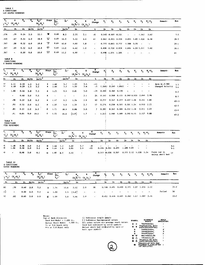
TABLE 7 D CONDITIONS LAR SHAPED WINDROWS
rro> <VV Ww h0T' Shape h£ j|Y.
<W /X. ) h Y • v 4 no (XJSY') (xo/yt)
i Change
ft lb/ft lb/ft' lb/ft' lb * lb lb lb lb lb lb lb
.276 .79 0.24
.420 .67 0.32
.367 .58 0.32
.367 .69 0.32
.367 - 0.50
TABLE 8 CONDITIONS
R SHAPED WINDROWS
3.0 12.5 ■ 0.68 8.5 2.35 3.1
6.0 18.8 U 0.69 12.9 5.43 2.4
6.0 18.8 "O" 0.64 i2.0 4.40 1 .B
6.0 18.8 "D" 0.64 12.0 4.40 2.0
9.0 1S.0 TZT 0.68 12.2 4.49
-6 0.34« 0.407 0.321 - - 1.542 2.62
41 0.862 0.993 0.938 2.033 4.83 1.550 6.38
0.775 0.665 0.752 1.508 3.70
0.82« 0.730 0.838 1.694 4.09 1.511 5.60
0.99» 1.571 1.306 -
7-5
28-3
29-1
30-1
45
-r ) (X-X.) o o 1
V Shape h/ hr' CX,hY') <Xo/yt)
e Change
ft ft lb/ft lb/ft' lb/ft' lb lb lb lb lb lb lb lb
5* 1.11 0.29 1.5 5.2 5" 1.18 0.29 1.5 5.2
) 1.00 ■ 0.40 3.0 7.5
- 0.40 3.0 7.5
) .98 0.32 2.0 6.2
' .93 0.32 2.0 6.2
' .85 0.32 2.0 6.2
i .41 0.64 9.0 14.1
TABLE 9 CONDITIONS
•JTED REVETMENT
1.00 5.2 1.50 3.4 1.00 5.2 1.50 3.6
1.25 9.4 2.81 3.0
- - - 3.1
1.47 9.2 1.56 2.8
1.50 9.4 1.50 2.7
1.75 10.9 0.88 3.0
4 1.75 24.6 [3.9] 1.7
) -11 ------ - -5 (.366) 0.240 (.060) - - - -
-19 0.269 0.269 0.170 - - - -
24 0.162 0.268 0.151 0.340 0.920 2.064 2.98
40 0.257 0.317 0.277 0.432 1.28 0.551 1.84
17 0.276 0.258 0.305 0.501 1.34 0.910 2.25
7 0.387 0.347 0.189 0.252 1.18 0.911 2.09
1.215 1-160 '-189 2.592 6.15 3.727 9.88
i
Bank EL 0.980 1 3 Chang ed Velocity 3
6
8
(0
12-
13-
47-
4
3
7
11
5
4
3
Shape -r ) (X -X.) o 01
hv hy'
UjhV) «VV
E Change
Run
ft ft lb/ft lb/ft' lb/ft' lb lb
0 1.18 0.58 3.0 5.2 *■ 1.48 7.7 2.30 3.7 * 1.36 0.58 3.0 5.2 * 1.14 5.9 2.95 3.4
0.48 3.0 1.40 8.7
0.224 0.331 0.209 1.286 2.05 5-4 5-5
0.517 10.520 0.507 0.571 2.12 1.228 3.34 Flrat run In ,, j walnut shell bed
TABLE 10 D CONDITIONS lENTED WINDROWS
i-ro> (VV Shape h>
h>
hf hr'
(XjhY1) <Vyt>
i Change
Remark» Run
ft ft lb/ft lb/ft' lb/ft' % lb lb lb lb lb lb lb
83 .70 0.40 3.0 7.5 4 1.54
3] - 0.40 3.0 7.5 « 1.00
52 .62 0.60 3.0 5.0 (JJ 1.00
11.6 2.12 2.0
7.5 13.0] - 5.0 1 .46 2.0
18 0.518 0.491 0.490 0.571 2.07 1.054 3.12
0.452 0.416 0.449 0.360 1.67 1:487 3.16
21- 2
50
22- 2
Notes: Top o(
Sand Wal iiu
Bank Elevation Bed Model - 1.200 ft. t Shell Model 1.500 ft. 0.6 Depth only
t 0.8 Depth only
() Indicates single sample [] Indicates EKtrapolated values All other values are average reach values Sand bed indicated by solid symbols Walnut shell bed inijeated by open or hall open symbols
♦ *
TT TT ▲ A
WINDROW R SHAPE GRAI
TRAPEZOIDAL TRAPEZOIDAL WITH CAPS(SEGMENTED)
TRAPEZOIDAL TRAPEZOIDAL TRAPEZOIDAL RECTANGULAR TRIANGULAR
TRIANGULAR WITH GAPS (SEGMENTED)
TRIANGULAR WITH 2ND WINDROW PLACED AFTER 1ST DEPLETED
than the scalloped bank of a natural condition. If the supply of stone from the windrow is exhausted before the revetment stabilizes, the continual downward movement of the stone eventually exposes the upper portion of the underwater bank. This exposed area will erode and the overtopped revetment will ultimately fail. See Photo 13.
30. The stone in the revetment actually moves in two directions, downward and riverward. The riverward movement of the stone complicates the design of the windrow revetment in that it appears to be related to the initial underwater slope of the bank, which must be determined by inspection, and to the maximum scour depth, which cannot be accurately predetermined.
31. To mathematically define the final revetment shape as a function of the windrow shape, (See Plate 1) it is assumed that the majority of the stone in the windrow cannot be transported by the stream velocities. The weight of the stone forming the revetment will then approximately equal the weight of stone which is eroded from the windrow and, therefore, may be expressed as:
or:
and:
where:
u wr
xl(hL Y') = Pr (7L Y")
X^h Y») = Yt(Z2 + I)0*5 (t Y") CD
Wu = weight of stone used from windrow
wr = weight of stone in revetment blanket
Xj^ = lateral erosion of windrow at top of bank
Pj. = Yt (Z + 1) = the slope length of the revetment
Z = XQ/Yt = cotangent of revetment slope
XQ = base width of revetment
*t = D + Yg = depth to toe of revetment
D = depth adjacent to eroding bank line
Yg = scour depth
h = average height of eroded windrow
t = average thickness of revetment normal to the slope
L = horizontal length along bank line
Y,= bulk unit weight of stone in windrow
y"= bulk unit weight of stone in revetment
(For all practical purposes Y' may be assumed equal to Y")
11
32. The path the stone follows after landing on the underwater bank slope may be defined by a "settling" angle such that:
where: a = Arccot ( A/Yt) (2)
a = settling angle
A = X -X-, = horizontal distance stone moves riverward
33. The above expressions, at this point, still cannot be used to design a windrow revetment. The required stone size and revetment thickness can be determined from standard procedures, but three of the above variables will be unknown. They are, the revetment slope, the scour depth, and the distance the stone moves riverward.
34. Using the results from the model tests, attempts were made to correlate these three variables with various parameters. No statistically significant relationships could be derived for either the revetment slope or the scour depth.
35. In contrast to the above, a very good relationship was developed for the "settling angle." See Plate 7. The relationship obtained was:
A /Yt = 1.2Z - 1.1 ; 1.8 <_ Z <. 3.6 (3)
Mlniaum Application Rate.
36. In the general usage of the term "application rate," the quantity of stone needed for a revetment is expressed in tons per foot of bank line. This can be misleading in that it is the amount of bank cover, or tons per square foot of bank, that is important. Simply placing a specified quantity of stone in a windrow may not produce a successful revetment. A certain amount of lateral erosion must occur. See Plate 1. If the limits of the windrow, X,, are less than the extent of the lateral erosion, X^, the revetment will have an insufficient supply of stone and will fail by overtopping. See Photo 13. Even if twice the amount of stone needed were to be applied (within a distance less than X,), it would fail because the revetment which would form would not extend to the water surface and the excess stone would be wasted simply by the fact that the revetment thickness would be greater than needed. If the amount of lateral erosion, X,, cannot be tolerated, then another method of bank stabilization must be used. As may be seen from equation 1, the minimum "application" rate may vary from site to site depending upon the slope length of the revetment. Minimum application rate also implies a resulting minimum revetment thickness. The windrow revetment samples In each test were averaged and nondimensionalized so as to express the revetment thickness in terms of the average stone size by the following:
12

So - Vr^
1+e
= revetment sample weight needed for a revetment layer thickness of one stone diameter
Ag = area of revetment sample =0.25 square feet
" G = specific gravity of stone = 2.76 Y = specific weight of water = 62.A lb/ft e = void ratio of stones; average value = 0.95
if S = jreveClient sample weight then S^ = _t
S d o ur
See Table 5 for specific values of SQ. The values of S/SQ have been plotted on Plate 8 versus the following nondimensional parameter expressing shear force of the water to the opposing force of the revetment stone weight.
F =
where
<Y8 ~ Y)dr
-2 T = Y v
(32.6 log10 12.2YQ' = local shear force above revetment toe
As may be seen from Plate 8, there is considerable scatter. However, there is a well defined lower limit which possibly defines the minimum revetment thickness for specific values of F.
Shape of Windrow.
37. The cross sectional shape of the windrow affects the average height, h, of the segment of windrow eroded, and therefore affects the volume of stone used. See Appendix B. The triangular shape will produce an average height which will vary from a maximum value equal to the initial height to half this value if the entire windrow is used. Therefore, the volume of stone spilling onto the bank will be a maximum initially with the volume diminishing as the erosion progresses. The average height of the trapezoidal shape will be constant throughout all but the last portion of the windrow where it will behave similar to a triangular shape. Here, the volume of stone spilling onto the bank will be constant except for the very last portion where it will diminish. The rectangular shape will function basically the same as the trapezoidal except that an additional quantity of stone exists at the beginning of this type windrow which will burst out of the containment trench when the eroding bank can no longer contain it.
38. In practice it has always been desirable to construct revetments with more stone in the toe zone than elsewhere. Considering the above three shapes, one would expect that both the rectangular and the triangular shapes, because of the initial surge of stone from these windrows, would produce this effect. Also one would expect the trapezoidal shape to produce a revetment of uniform thickness. The revetment samples taken from the top, middle, and bottom of the revetments were used to verify these expectations.
13

39. A ranking method was used to try to detect a trend among the different shapes. The samples from each test were ranked 1, 2, or 3, with the smallest weight sample being ranked 1. These rankings were then averaged for each windrow shape and location. See Table 12.
WINDROW TABLE SHAPE
12 COMPARISONS
Windrow Shape
Number of Tests
Average Top
Rank Middl
of e
Sampl«
Bottom
(Sand Bed Model)
Triangular 6 2.2 2.2 1.5
Trapezoidal 2 3.0 2.0 1.0
Rectangular 1 2.0 3.0 -
1.0
(Walnut Shell Bed Model)
Triangular 1 1.0 2.0 3.0
Trapezoidal 22 1.6 2.4 2.0
Rectangular 4 1.8 2.0 2.2
40. The rankings on the walnut shell bed samples were in agreement with the expectations listed above while those from the sand bed model were not. Considering that in the sand bed model the revetment samples tended to thin from top to bottom, and also that the revetment slopes were flatter, it would seem to suggest that the tests in the sand bed model were affected by the inability of the flow to scour the sand material from around the individual stones.
Effects of Stream Velocity.
41. The windrow revetment was tested over a wide range of velocities. See Tables 6, 7, 8, 9, and 10. The purpose being twofold:
(1) To determine the effect different erosion rates would have on different windrow configurations.
(2) To determine under what conditions the revetment might fail.
14

42. None of the revetments using gradation 1 or 4 failed by leaching even though very high velocities were used. In some of the tests the revetment was allowed to stabilize at a low velocity and then the flow rate was increased to a high velocity which was sustained for many hours. Several of the tests which were run using gradation 1 were intentionally constructed with an insufficient supply of stone in the windrow and these windrows failed by overtopping. It was found that the stone in the revetments of these runs still clustered together even though the supply was inadequate.
Stone Gradation and Size.
43. Seven tests were made using a stone gradation other than gradation 1. See Table 6. Four of these tests were conducted on gradation 2, one on gradation 3, and two on gradation 4. The stone in gradation 2 was basically all the same size, d = 0.05 ft. Gradation 3 also consisted of only one size, d = 0.02 ft. Two of the tests with gradation 2 failed and the failures can be attributed to leaching. The two succeeding tests using gradation 2 did not fail even though extremely high velocities were used over an extended period of time. The reason being that a thicker windrow was used which formed a revetment greater than one stone diameter in depth. Gradation 3 also formed revetments which were greater than one stone diameter thick.
44. These tests indicated that revetments formed by a graded stone would not fail by leaching, but revetments formed of a uniform gradation could fail by leaching. It is possible that because of the grain size of the bank material mechanical blockage prevented the graded stone from failing by leaching.
Different Bank Heights.
45. Different bank heights do not appear to have any adverse effects on the formation of the revetment. Four tests were conducted using different bank heights, and the only noticeable effect on the revetment was that the alignment was not as uniform as that produced with low bank heights. See Photo 15. There was some influence on the quantity of stone eroded which possibly resulted from the fact that the portion of the exposed bank between the water surface and top of bank captures part of the revetment material.
V. CONCLUSIONS
46. The analysis of the model data defined the parameters associated with the formulation of the windrow revetment. Model data were obtained from windrowed stone placed along the bank line in an actively eroding area. The channel geometry simulated the most severe degree of curvature expected to occur under prototype conditions. During the model study, two different types of bed materials were used along with four different stone gradations, three different windrow shapes, and a wide range of velocities. The following conclusions with respect to the initial objectives were determined.
Mechanics of Windrow Revetment Formation.
47. The windrow revetment in concept is simple. Stone is placed along an eroding bank line which is eventually undercut by the stream. The stone then moves down the bank line to form a blanket which halts further erosion. In reality, the formation of this type of revetment is complex. Initially, the
15

lateral erosive force of the stream undermines the wLndrowed stone causing some of the stone to fall onto the bank. This stone slows the lateral erosion of the bank but causes an increase in the vertical erosion along the leading edge or toe of the newly forming revetment. This vertical erosion is believed to be caused both by turbulence or eddies around individual stones and by a diminished supply of material from the bank. The initial quantity of stone forms an unstable revetment which during the vertical erosion process is constantly adjusting itself as the toe of the revetment advances into the scour area, this results in a riverward movement of the stone. If a sufficient supply of stone is available from the windrow, a semi-stable revetment will eventually be formed as dictated by the intensity of the erosive forces of the stream or the structural integrity of materials comprising the bank. It should be noted that the riverward movement of the stone causes a thinning of the revetment blanket. If no riverward movement of stone occurred, the vertical thickness of the revetment blanket would be the same as the windrow height and there would be no design problem. It is important that the designer have some knowledge of the amount of scour which might be expected to occur. It is suggested that this be ascertained from other structures in the vicinity of the proposed windrow revetment, or by evaluating maximum scour depths existing upstream and downstream of the proposed revetment. Equation 1 defines the relationship between the amount of stone needed in a windrow to provide a blanket configuration for various slopes and thicknesses.
X^h Y') - Yt(Z2 + l)0*5 (t Y") CD
Although the model results indicated that revetments with less than one stone diameter layer would function, it is suggested that the minimum thickness of 1.5 diameter be used for design. It was also found that the "settling angle" of the stone was related to the revetment slope.
A/Yt = 1.2Z - 1.1 (3)
Considering that the revetment slopes in the sand model were flatter than the revetment slopes in the walnut shell model, it would appear that the more easily a bank material may be eroded then the steeper the revetment slope. Small stones, such as used in this study, also have smaller angles of repose than do large stones which would be used on a river or stream. Until sufficient prototype data is available, it is suggested that the minimum model revetment slope value of 1.7 be used. This then gives a A/Y value of 0.9.
Application Rate.
48. The application rate is the weight of stone applied per length of bank line. The amount of stone in the windrow dictates in part the degree to which the lateral erosion will occur, however it is important to realize that a certain amount of lateral erosion has to occur in order to permit the stone to feed down and cover the final bank slope. If all the windrow is within the erosion zone, X.,, all of the stone will be undermined and the revetment overtopped, with failure occurring because of insufficient horizontal supply.
Windrow Cross Section.
49. The shape of the windrow as originally placed on the upper bank affects the average height, h, of the segment of windrow eroded, and therefore affects the volume of stone spilling onto the bank. A triangular shape will
16

release a volume of stone which will diminish from a maximum value to zero. The volume of stone released from a trapezoidal shape will be constant throughout all but the last portion of the windrow, where it will behave similar to a triangular shape. A rectangular shape will function basically the same as the trapezoidal, except that an initial surge of stone is released from the containment trench when the eroded bank can no longer sustain it. Generally speaking, the rectangular shape was found to be the best windrow shape. This shape supplies an initial surge of stone which counters the thinning effect of the scour in the toe zone of the forming revetment. The reamining portion of the windrow then provides a steady supply of stone" to produce a uniform paving. The second best windrow shape was the trapezoidal shape. It has one advantage over the rectangular shape in that no trench is needed to contain the windrow stone. This shape supplies a steady supply of stone similar to the rectangular shape. The triangular shape was probably the least desirable shape. This shape supplies more stone initially, but the quantity of stone diminishes as the windrow is undercut.
Strea» Velocity.
50. The velocity and characteristics of the stream dictate the minimum size stone that must be used in the revetment.
51. Stone Gradation. None of the windrow revetments tested using either stone gradation 1 or 4 of Table 5 failed by leaching even though very high velocities were used. Tests using single stone sizes gave conflicting results. Two tests with gradation 2 failed, but the tests with gradation 3 did not fail. The nonfailure of the various revetments could possibly be attributed to mechanical blockage resulting from the size of the stone in respect to the model bed material. It is recommended that a well graded stone gradation be used for windrow revetments.
Stone Size.
52. The size of the stone used in the windrow is not a significant design parameter as long as the stone size Is large enough to resist being trans- ported by the stream.
Bank Height.
53. No definite conclusions were formulated on the effect of bank heights. The only noticeable difference in tests using high banks was a slightly ragged alignment. In the time lapse photos of these runs it was noted that the high banks have a tendency for large segments of the bank to shear and rotate slightly, whereas the low banks simply slough into the stream. The slight rotation of the bank segment probably induces a tendency for scalloped bank lines. Compare Photos 14 and 15.
54. Windrow revetments constructed on high river banks may lead one to believe that some of the stone is wasted or that more stone needs to be added to the windrow. These concepts may be erroneously formulated because quantities of stone will be scattered from the top of bank down to the water's edge. This stone is not wasted nor do additional quantities have to
17

be added to the windrow to pave this zone. This stone is part of the supply and simply has not been used as yet. In the case of a low bank most of this stone would remain in the windrow, but because of the greater distance between the windrow and the water's edge for the high river bank, it takes more time for the final quantities of stone to move into the water. Eventually, if this stone is needed, it will work its way down. The object of the revetment is to protect only the portion of bank exposed to the erosive force of the water and not to armor the entire bank line top to bottom.
Noncontinuous Revetnent.
55. The use of noncontinuous windrow revetments appears to be feasible. How- ever, because of numerous additional variables associated with this method, only runs demonstrating the applicability of the technique were made. See Photo 16.
Example
The following example is included to demonstrate the design of a windrow revetment.
Given:
Stream Depth along bank line D = 20 ft.
Remarks:
From field surveys
Assumed Scour Depth Ys = 10 ft.
Average Stream Velocity V = 4 fps
From field observations at nearby structures
From field surveys
Assume cotangent of revetment slope Z = 1.7
Suggested value until verified by prototype measurements
Mean diameter of windrow stone <*r = 1.0 ft.
Desired revetment thickness t = 1.5 d 1.5 ft.
Specific gravity of windrow stone G = 2.6
Void ratio of windrow stone e = 0.50
From other calculations
As required
From analysis
From analysis
Computations
Toe depth Yt = D + Ys = 20 + 10 - 30 ft.
Base width of revetment XQ - Z Yfc - (1.7)(30) - 51 ft.
18

Computations (Cont'd)
Cotangent of settling angle Equation 3 lggested v prototype
A /Y =0.9 Suggested value until verified by
Riverward movement of stone A = (0.9)(30) = 27 ft.
Eroded width of windrow X = X0 - A Xx = 51 - 27 - 24 ft.
Revetment slope length Pr = Yt(ZH-l)0,5 = 59 ft.
Bulk unit weight of revetment material Y" - (SG)( YS) - (2.6)(62.4) = 108 lb/ft3
1 + e 173
Weight of stone in revetment per foot of bank line W = p ~l Y" w£ = (5*9)(1.5)(108) - 4.8 tons/ft.
2000
Since this is an average value, the quantity of stone and windrow width should be increased. It is suggested that this be 1.25 Wr and 1.25 X-^. Then
X4 = 1.25 (24) - 30 ft. Ww = 1.25 (30) (4.8) = 7.5 tons/ft. placed uniformly
(24) within a 30 ft. wide windrow w
Where X^ = Base width of windrow as constructed W = Application rate in windrow as constructed.
19

APPENDIX A
BIBLIOGRAPHY

BIBLIOGRAPHY
1. McEwan, John S., "Bank and levee stabilization, lower Colorado River," Journal of the Waterways and Harbors Division, Proceedings of the American Society of Civil Engineers.
2» Schumn, S. A., "The shape of alluvial channels in relation to sediment type," Geological Survey Professional Paper 352-B, United States Department of Interior.
3. Task Committee on Channel Stabilization Work Committee of Regulation and Stabilization of Rivers, "Channel stabilization of alluvial rivers progress report," Journal of the Waterways and Harbors Division, Proceedings of the American Society of Civil Engineers.
4. U.S. Army Corps of Engineers, "Operation and function of the Mead Hydraulic Laboratory," MRD Hydraulic Laboratory Series Report No. 1, U. S. Army Engineer District, Omaha.

APPENDIX B
WINDROW SHAPES

APPENDIX B
Trapezoidal Windrow.
1. The trapezoidal windrow, see Plate B-l, is constructed by dumping stone onto the top of the bank forming a uniform height windrow. Presumably the front and back slopes of the windrow will shape themselves to the natural angle of repose of the stone. As the windrow erodes, the front slope will retain itself at the angle of repose of the stone and the effective height will be the same as the initial height of the windrow. The weight of stone used per foot of windrow, W may be represented by the following:
Wu = Xl<ho Y') " Xl("h Y*> (B1>
with the following limitations,
X
where:
i < (x4 - Vr>
^r = cotangent of angle of repose for stone
h = maximum initial height of windrow
^o = average initial height of windrow
for trapezoid
then
and
- h - h o "o
hY'= hQ Y' (B2)
h Y ' = 1 (Trapezoidal Windrow) (B3) h Y ' o

Triangular Windrow.
2. The triangular windrow, see Plate B-2, is constructed by dumping stone onto the top of the bank, forming in cross section a triangle, with the front and back sides of the windrow sloping at the angle of repose of the stone. As the windrow is eroded, the effective height of the windrow, h, will vary from the initial value, h to the average value of hQ/2. The weight of rock used per foot of windrow may be expressed by:
W X4ho - (x4 - T
X,) ( Vl Y' = xx (h Y') (B4)
where b^ y ' = (X^ - X^ hQ y'j the weight of stone per unit area of
XT windrow remaining on the bank
then h Y ' - (2X4 - Xl) hQ y '
X4
with h = o hQ/2
and h Y. - 2-Xl
h Y * o ' X4
Rectangular Windrow.
(Triangular Windrow) (B5)
3. The rectangular windrow is constructed by placing the rock into a pre- formed rectangular trench. Except for the initial surge of stone from the trench as the stone burst out, the relationships will be the same as the trapezoidal h" y ' = 1 (B6)
h Y ' o

BEFORE EROSION
/ ^Q^V7 k
X4 _2_
^ XrTh \
AFTER EROSION
I?\
Weight of rock used from windrow
u Xi(hY')
V
MISSOURI RIVER DESIGN STUDY
WINDROW REVETMENT MODEL TESTS
TRAPAZOIDAL WINDROW U. 5. ARMY ENGINEER CORPS OF ENGINEER»
DISTRICT, OMAHA OMAHA, NEBRASKA
PLATE B-l

BEFORE EROSION
AFTER EROSION
We/g/rf of rock used from windrow equals /n/'fa/ we/gin f m/ni/s f/na/ we/ght or? bank
w [■
Xith _ Oi^ - *l) hfly' XX (hy')
Ä1. - 2 - x*
I MISSOURI RIVER DESIGN STUDY
WINDROW REVETMENT MODEL TESTS
TRIANGULAR WINDROW U.S. ARMY ENGINEER DISTRICT, OMAHA CORPS OF ENGINEERS OMAHA, NEBRASKA
PLATE B-2

APPENDIX PHOTOS

Typical bank line looking upstream in the uncontrolled portion ot the Missouri River about mile 1332, near Bismarck, N.D., known as the Dry Point Area.
2. A windrow revetment near Vermillion, S.D., in the Vermillion River Chute Area about Missouri River Mile 771. Note natural appearance of bank. Windrow may be seen near top of 20-foot bank. The top of the revetment is visible near the water's edge. Depth to toe of revetment is about 20 feet.

3. Windrow revetment near Fort Calhoun, Nebraska, about Missouri River Mile 639.
4. Windrow revetment near Omaha, Nebraska, about River Mile 634. Note minimal site preparation.
Vv.tf M
5. Same location as Photo 4. Erosion just beginning to undermine windrow.
fit- ** t'^*"*" "
r Vf*
IPlilljl»»'"'
Windrow revetment near Plattsmouth, Nebraska, on the Platte River about 2 miles upstream of the confluence with the Missouri River. Note natural appearance of bank. Windrow material slowly feeding down to water's edge through bank vegetation during initial revet- ment formation stage.

7. Reconstruction of sand bed model. Horizontal bar in midsection ■ photo fixed at left to center point of curve. Right end of bar fr. to slide along outside edge of basin. Person at right sliding e; of bar while person in channel removing excess material from : front of template attached to bar.
L»*H
[&
*jBfc'":.-i :|
8. Reconstructed channel prior to start of run 3. Flags were use initially to locate centerline of windrow at 1 foot intervals.
9. End of run 3 conditions looking upstream.
10. Oblique view of upstream end of windrow revetment at end of run 3.

v*-*.
f :g& T^SS» ■-»it?.:1
"8 o cd
t-H CU Cu o
(-1 •
°£ V
4J C T3 & Q HI CU P.
CJ g
U »4-1 CO
o
<Ti
<d cd
o
<u co
o
o C 0)
4->
CO «4-1 o cu
cd o- a» 4-i o
cd cu co cu
co > ,C " O 4J
0 ^ <U
a> 3 > o U T3
CU t3 O CU 0 co -a
.o o e o
T3 CO e
3 ^ cu o e o c o h4 -H N
g,.
12. Guide used to sample 0.5 foot by 0.5 foot section of revetment.
13. End of run 40 conditions looking upstream. Insufficient supply of stone in windrow. Note revetment continued to move into scour at toe zone exposing bank near water's edge. Upper bank zone eroded and revetment was overtopped.
I \ J*:.*
14. End of Run 27 conditions looking upstream. Normal appearance of windrow revetment.
15. End of run 41 conditions with high bank. Note irregular appearance of bank line.

16. Looking upstream during testing of segmented windrows. Note
scalloped bank line.

APPENDIX D
PLATES

MISSOURI RIVER DESIGN STUOY
WINDROW REVETMENT MODEL TESTS WINDROW REVETMENT
DEFINITION SKETCH U. 3. ARMY ENGINEER DISTRICT, OMAHA CORPS OF ENGINEERS OMAHA, NEBRASKA
PLATE

Basin Wall5foHor7s-
0
-Water Surface ' Monitor/ng 7ubes
5iilling Area For
Returned Wale r
Mote- P-l,REandP-3Are Points
Of Orioin For Curves.
i
©

'Ho/75 v20
1 .
Model dos in Wal Is ~^^ 30
1 40
1
race
P-2- \v \
vk, A
col no'
/ °
>1 rmored Banks-—~° i
20
£1.0.60
30
SECT/ON AT BEG/M/NG OF TEST
*o P-3

40 m&:
STA. 73.7
f To Settling Basin 'And Kecirculah'on Pumps i
-70
80
MISSOURI RIVER DESIGN STUDY
WINDROW REVETMENT MODEL TESTS
MODEL BASIN BED MATERIAL! SAND
U. S. ARMY ENGINEER DISTRICT, OMAHA CORPS OF ENGINEERS OMAHA, NEBRASKA
CD PLATE 2
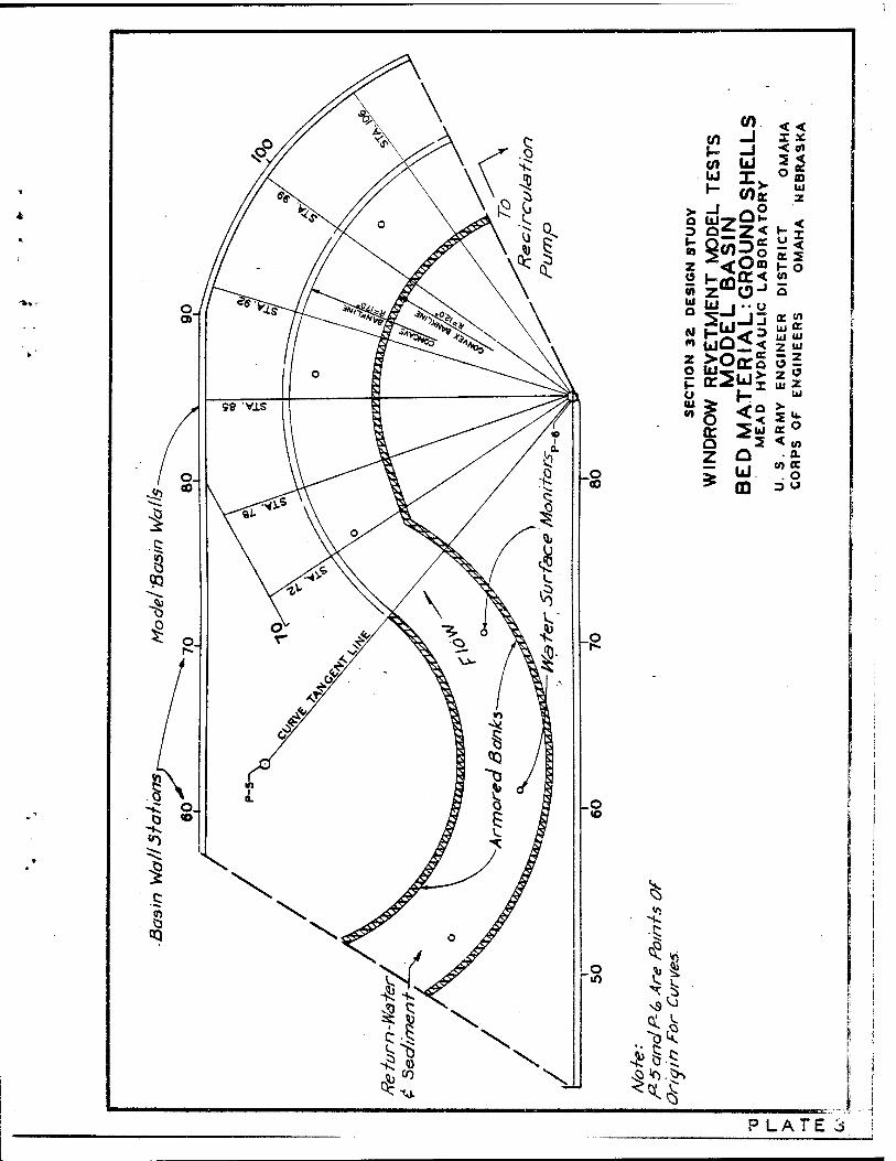
o
V)
u H
_l UJTP
(0
bJ
°<O0Q
iba£:S 5
< < X X < tf) 2 <
UJ z
1-2 y <
h: ° 0)
0) Ul o
cvl « z o
u IU (0
IU j "O
Q z
hr
2 o u m
(E to UJ oc Ul UJ Z UJ 3^ Z « Ul z
UJ > «O <«
■ 0. co ee
. O D o
^. ^ <0
H^
g
^» o «, § «O U
X 3 ^Vj
<U ^)K
4?8-$ vo^.O*
PLATE 3
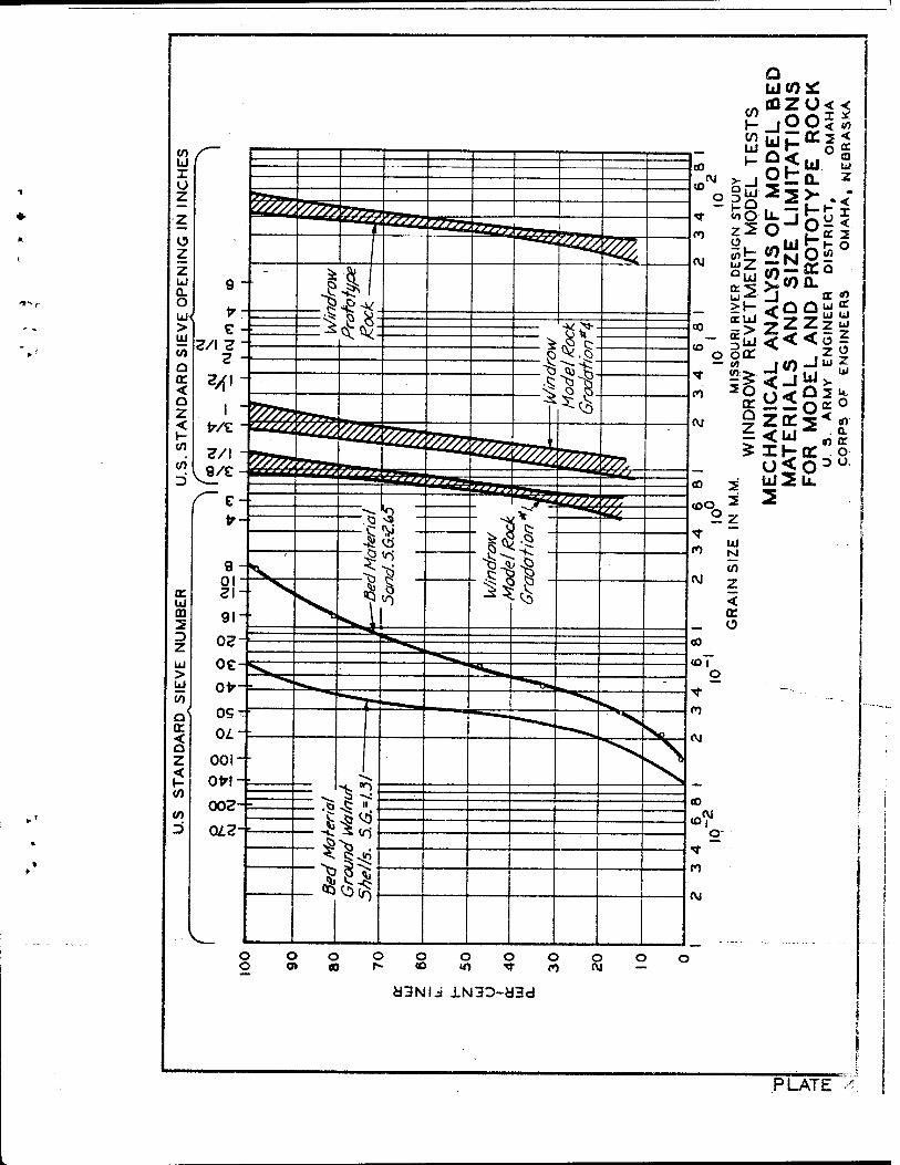
*■
*
PLATE
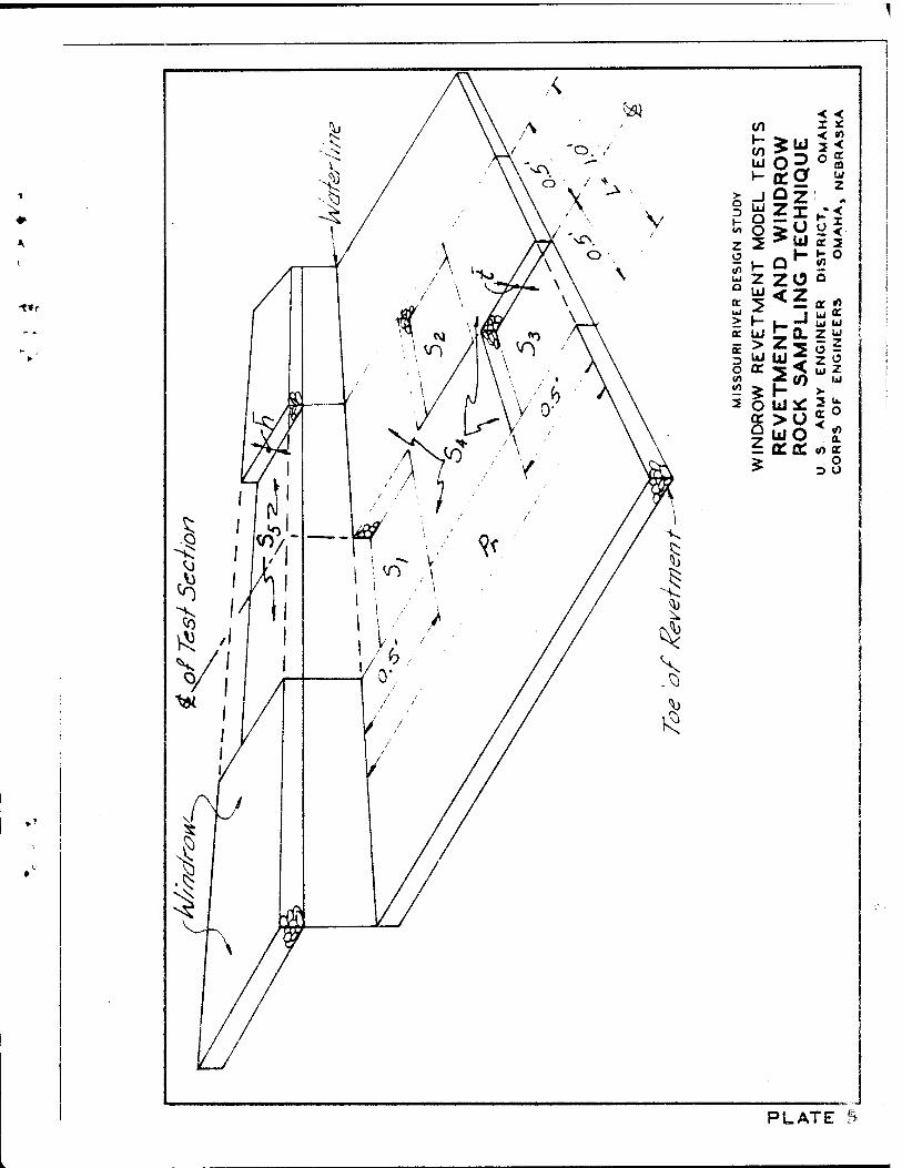
-t*r
V) H (O UJ 1-
_l Ld Q O 2 »- Z u
h- UJ > UJ
e 3 O (A
s * 2 O cc Q z
< <
>UI K 2
ZO ö
2^ u Z .10 w
r- >
ujo 2 o
3 O
PLATE 5

0.3 0.4 0.5 0.6 0.7 0.8
ÜJ
1.35
1.30
.25
1.20
Z 1.15
i- liJ 1.05
UJ
1.00
0.95
0.90
17.2 17.1 17.0 16.9 16.8 I'
RADIUS
©
NOTE: t

16.9 16.8 16.7 16.6
RADIUS IN FEET 16.5 16.4 16.3 16.2
NÖTE: NUMBERS FNDICATE FEET PER SECOND + MARKS LOCATION OF VELOCITY MEASUREMENT
MISSOURI RIVER DESK
WINDROW REVETMENT ISOVEL'
STATION £ RUN 31 TIME
U 5. ARMY ENGINEER DIS1
CORPS OF ENGINEERS C
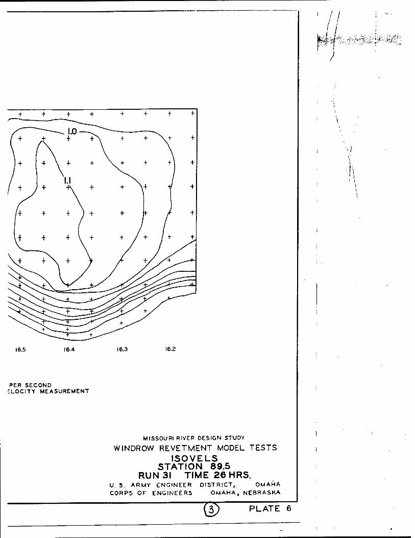
16.5 16.4
PER SECOND £LOCITY MEASUREMENT
16.3 16.2
MISSOURI RIVER DESIGN STUDY
WINDROW REVETMENT MODEL TESTS ISOVELS
STATION 89.5 RUN 31 TIME 26HRS.
U 5. ARMY ENGINEER DISTRICT, OMAHA CORPS OF ENGINEERS OMAHA, NEBRASKA
W PLATE 6
/ 7 /
I
}

4.8
4.0
%*- 3.2
A/ 2.4
1.6
0.8
-
-
/A A
m / A/A
■ ÜDy« V-JA... ,.„-,.,
— U*p Uy LJLJ
rhyHDB
o^ an /a a
-
1 1 ]
0.8
SYMBOL
■ □
a D a
-r TX A A
* 4
WINDROW SHAPE
TRAPEZOIDAL TRAPEZOIDAL WITH GAPSCSEGMENTED3
TRAPEZOIDAL TRAPEZOIDAL TRAPEZOIDAL RECTANGULAR TRIANGULAR
TRIANGULAR WITH GAPSCSEGMENTED)
1.6
ROCK GRADATION
2.4
z 3.2 4.0 4.8
z 3 4 I I
MISSOURI RIVER DESIGN STUDY
WINDROW REVETMENT MODEL TESTS COTANGENT OF SETTLING ANGLE VS
COTANGENT OF REVET. SLOPE ANGL£ U. S. ARMY ENGINEER DISTRICT, OMAHA CORPS OF ENGINEERS OMAHA, NEBRASKA
PLATE 7
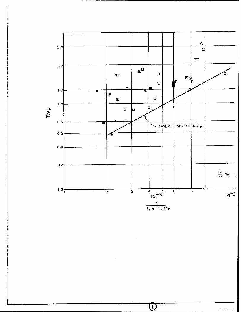
(ys " Y )^r
1X7
A
E
"ET
1
1 [ r D ^
0\ WER L .IMIT OF t/dr
i .. r dr 'b (G-0 < it-
5 6
r)di
SYMBOL
D
* n D B
TT
A
4
WINDROW SHAPE
TRAPEZOIDAL TRAPEZOIDAL WITH GAPSCSEGMENTED}
TRAPEZOIDAL TRAPEZOIDAL TRAPEZOIDAL RECTANGULAR
TRIANGULAR TRIANGULAR WITH GAPSCSEGMENTED3
ROCK GRADATION
2 3 4
I
MISSOURI RIVEF
WINDROW REVETK, t/dr versu:
U. S. ARMY ENGINEER
CORPS OF ENGINEERS
W
SYMBOL
D
* a D B
TX A
4
WINDROW SHAPE
TRAPEZOIDAL TRAPEZOIDAL WITH GAPSCSEGMENTED)
TRAPEZOIDAL TRAPEZOIDAL TRAPEZOIDAL RECTANGULAR TRIANGULAR
TRIANGULAR WITH GAPSCSEGMENTED)
ROCK GRADATION
'•$<¥ '""i-""„ft""' *
' I
2 3 4
MISSOURI RIVER DESIGN STUDY
WINDROW REVETMENT MODEL TESTS t/dr versus
X U. S. ARMY ENGINEER
CORPS OF ENGINEERS
Y s ~ Y)^r
DISTRICT,
OMAHA,
SI
OMAHA NEBRASKA
PLATE 8