leakage reactance & short circuit impedance testsengineering.richmondcc.edu/courses/eus...
TRANSCRIPT
Leakage Reactance & Short Circuit Impedance Tests
Leakage Reactance Measurement What is it? The measurement of the transformer impedance with the secondary winding short circuited by applying a voltage to the primary and measuring the corresponding current.
Ohm’s Law: Z=V/I Why we do it? • Assess physical condition of the transformer (Geometry of Specimen)
– Attempting to detect winding movement or deformation How we do it? • Using a single phase high current low voltage source • Measure voltage across and current through an individual winding
Leakage Reactance Measurement • The measurement of the reactive component of the transformer
impedance with the secondary winding shorted, voltage applied to the primary and measuring the corresponding current.
• With the secondary shorted, current is drawn by the primary in response to the counter flux from the secondary in order to balance the voltage.
• Measurements are sensitive to geometrical changes in the leakage flux path.
When We Run the Test
• Investigative Test – Responding to incident that questions the transformer’s health – Focused testing designed to detect specific problems
• Focused on the geometric integrity of the transformer Other tests that perform similar evaluations • Capacitance test
– General assess will not identify specifics
• Frequency Response Analysis (SFRA) – The Short Circuit measurement will provide independent confirmation
Leakage Flux definition
Theory Flux due to the current in the primary winding, that does not link the secondary and the flux due to the current in the secondary winding that does not link the primary winding.
Practical The flux that is not confined to the core for the entire length of it path. The flux which is present in the unit permeability space.
What is Unit permeability space: It includes the space between the windings, i.e. between the inner space of the outer winding and the outer space of the inner winding.

Model of a Two Winding Transformer
• Short Circuit Impedance: 𝑍𝑠𝑐 = 𝑅2 + 𝑋𝐿2
• Calculated from data obtained during the Impedance and Load Loss in the factory • Stamped on the Nameplate
• Leakage Reactance: XL • Only the reactive component of the Short Circuit Impedance

Fun Just Started !
• I2 creates opposing flux ᶲ2 attempting to reduce the flux created by Iex. However, since the total flux in the core must have the rate of change sufficient to balance V1, the primary flux increases to make up for the reduction.
• That increase is “supported” by an increase in the primary current. This is how information is transmitted from the secondary winding or from any other magnetically coupled loop (e.g., s. c. turn, shorted laminations, etc.) into primary winding.
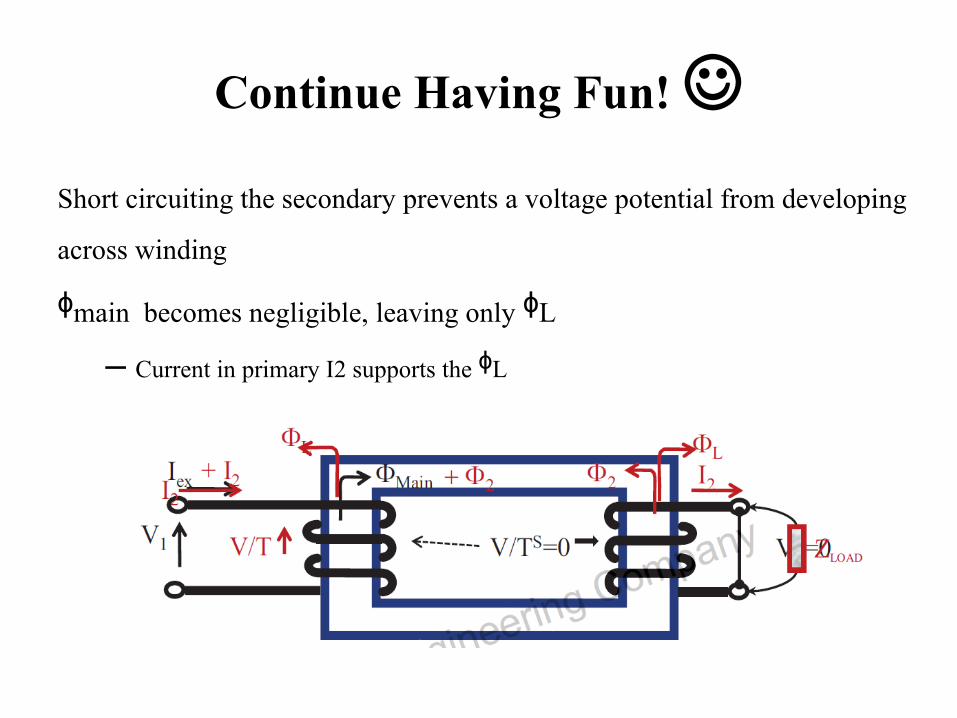
Continue Having Fun! Short circuiting the secondary prevents a voltage potential from developing across winding
ᶲmain becomes negligible, leaving only ᶲL – Current in primary I2 supports the ᶲL
FUN IS OVER
With the secondary winding electrically SHORTED the current in the primary winding is only required to support
the leakage flux. Do you remember excitation current test?
IT WAS OPEN CIRCUIT TEST
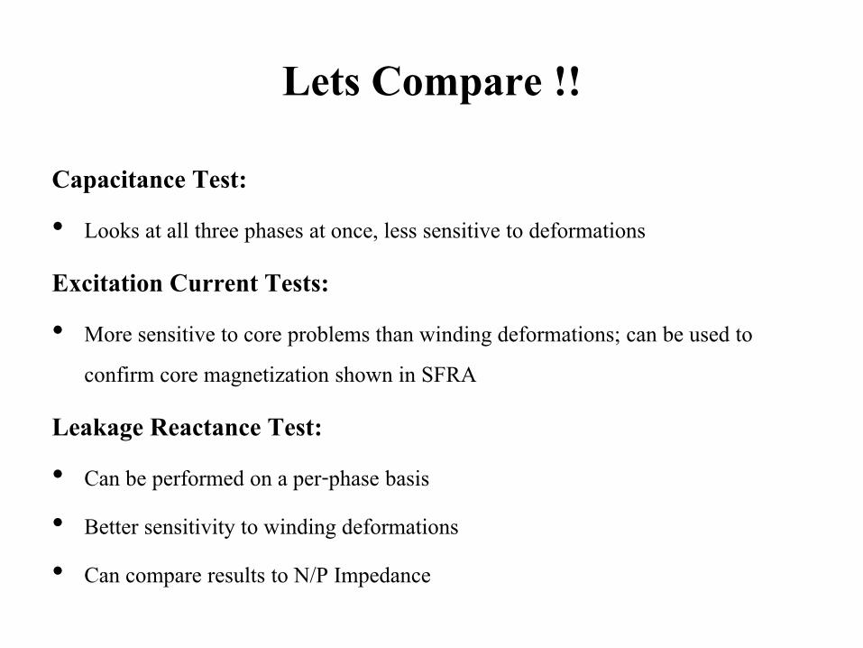
Lets Compare !!
Capacitance Test: • Looks at all three phases at once, less sensitive to deformations
Excitation Current Tests: • More sensitive to core problems than winding deformations; can be used to
confirm core magnetization shown in SFRA
Leakage Reactance Test: • Can be performed on a per-phase basis • Better sensitivity to winding deformations • Can compare results to N/P Impedance
Leakage Reactance V.S. Excitation Current
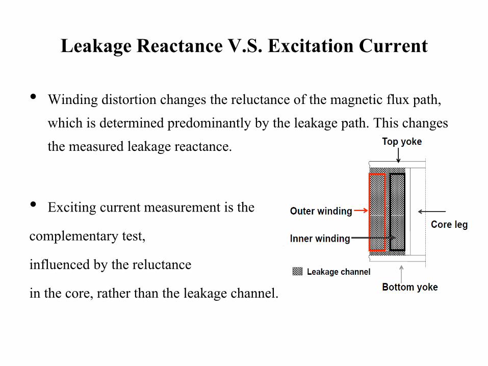
• Winding distortion changes the reluctance of the magnetic flux path, which is determined predominantly by the leakage path. This changes the measured leakage reactance.
• Exciting current measurement is the complementary test, influenced by the reluctance in the core, rather than the leakage channel.
Short Circuit Impedance
• A transformer with a higher short circuit impedance (%Z), has more losses built into the transformer
• Efficiency vs. durability • A transformer with a higher %Z, will not be as stressed
as one with a lower %Z
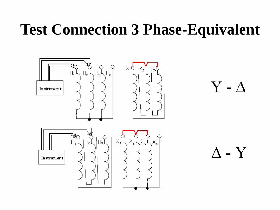
Test Connection 3 Phase-Equivalent
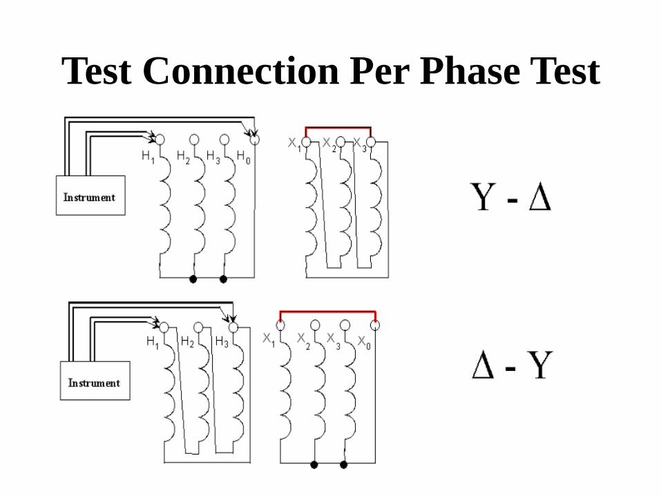
Test Connection Per Phase Test
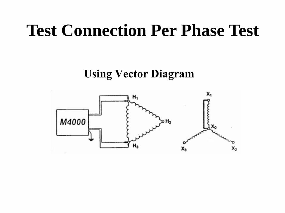
Test Connection Per Phase Test
Using Vector Diagram
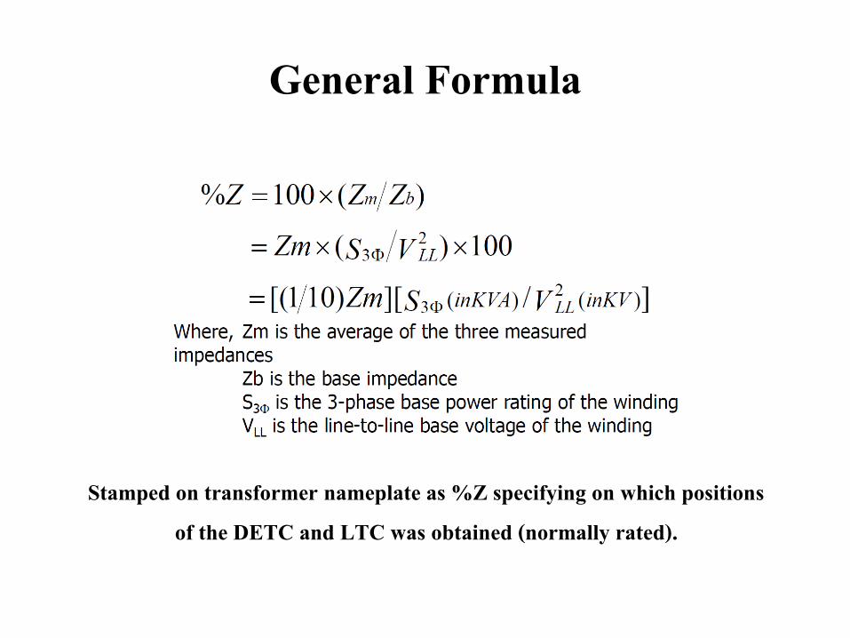
General Formula
Stamped on transformer nameplate as %Z specifying on which positions of the DETC and LTC was obtained (normally rated).
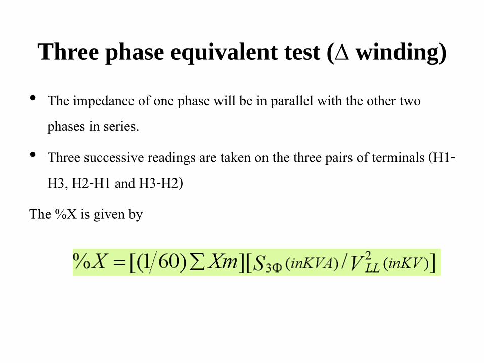
Three phase equivalent test (∆ winding)
• The impedance of one phase will be in parallel with the other two phases in series.
• Three successive readings are taken on the three pairs of terminals (H1-H3, H2-H1 and H3-H2)
The %X is given by
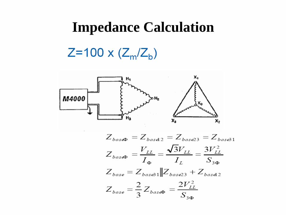
Impedance Calculation
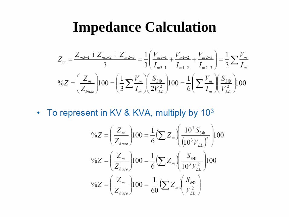
Impedance Calculation
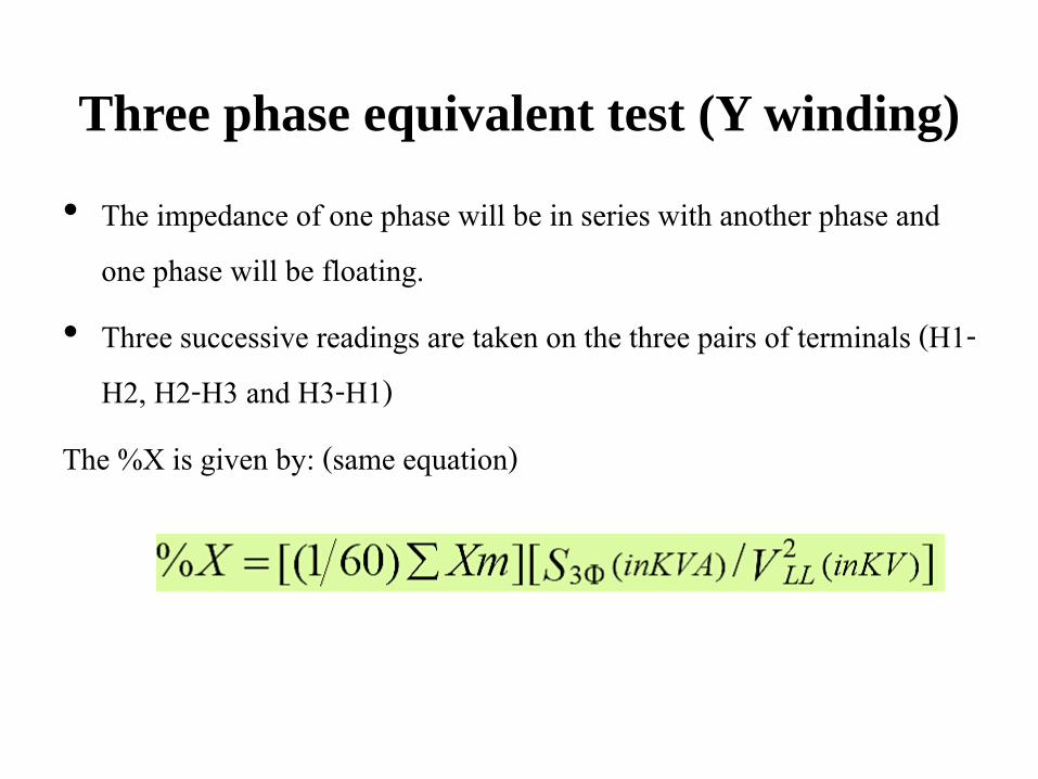
Three phase equivalent test (Y winding)
• The impedance of one phase will be in series with another phase and one phase will be floating.
• Three successive readings are taken on the three pairs of terminals (H1-H2, H2-H3 and H3-H1)
The %X is given by: (same equation)
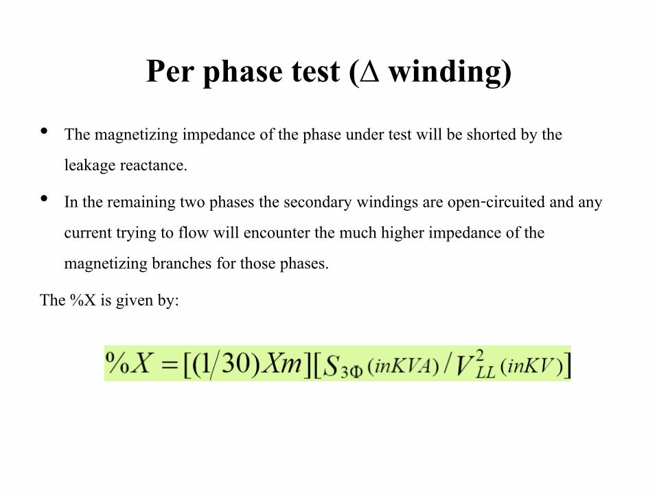
Per phase test (∆ winding)
• The magnetizing impedance of the phase under test will be shorted by the leakage reactance.
• In the remaining two phases the secondary windings are open-circuited and any current trying to flow will encounter the much higher impedance of the magnetizing branches for those phases.
The %X is given by:
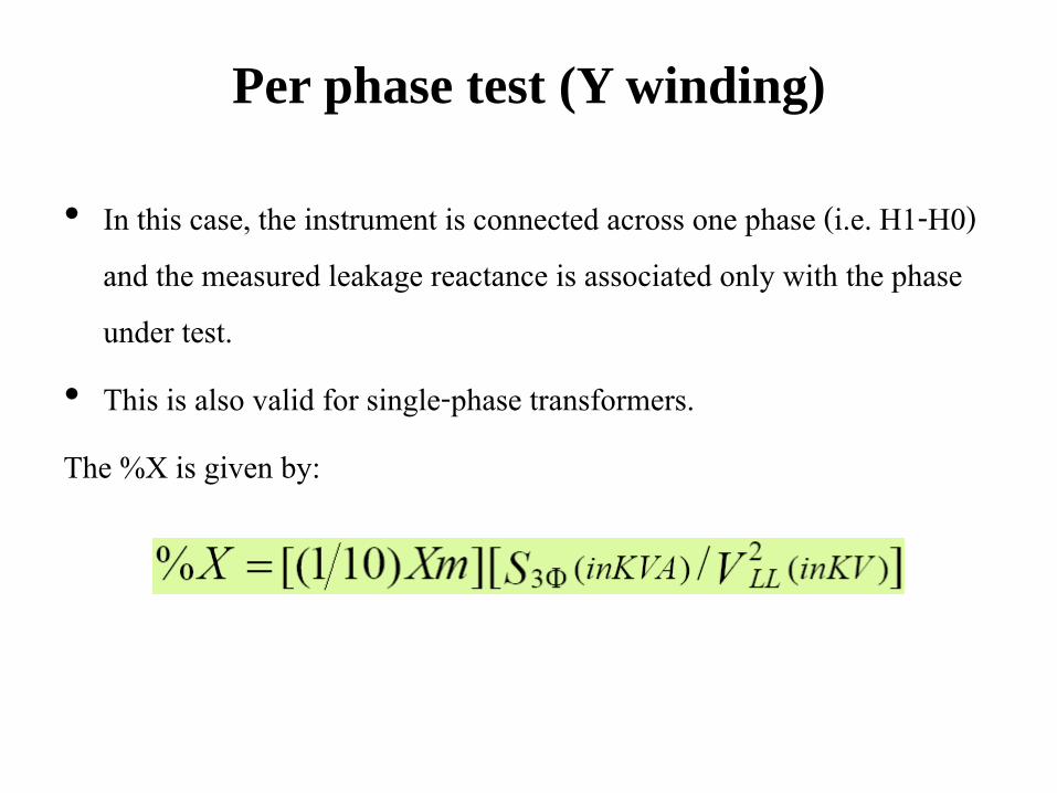
Per phase test (Y winding)
• In this case, the instrument is connected across one phase (i.e. H1-H0) and the measured leakage reactance is associated only with the phase under test.
• This is also valid for single-phase transformers. The %X is given by:
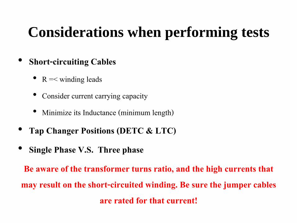
Considerations when performing tests
• Short-circuiting Cables • R =< winding leads • Consider current carrying capacity • Minimize its Inductance (minimum length)
• Tap Changer Positions (DETC & LTC)
• Single Phase V.S. Three phase
Be aware of the transformer turns ratio, and the high currents that may result on the short-circuited winding. Be sure the jumper cables
are rated for that current!
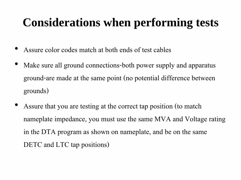
Considerations when performing tests
• Assure color codes match at both ends of test cables • Make sure all ground connections-both power supply and apparatus
ground-are made at the same point (no potential difference between grounds)
• Assure that you are testing at the correct tap position (to match nameplate impedance, you must use the same MVA and Voltage rating in the DTA program as shown on nameplate, and be on the same DETC and LTC tap positions)
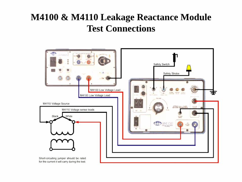
M4100 & M4110 Leakage Reactance Module
Test Connections
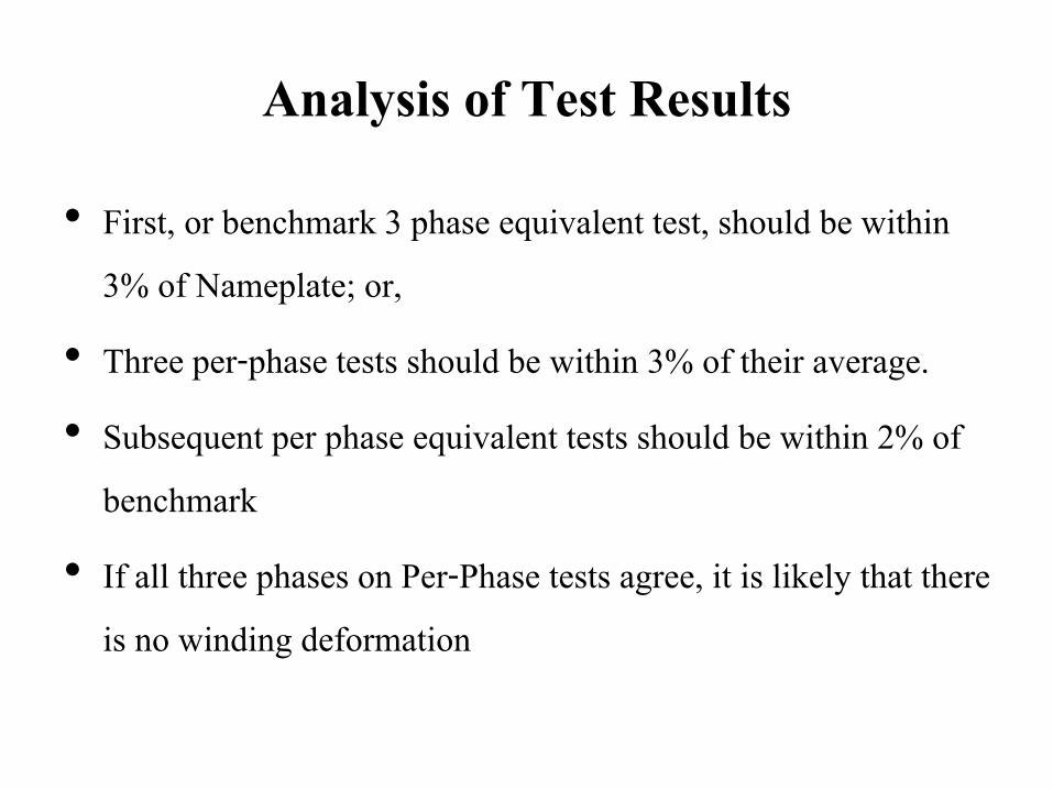
Analysis of Test Results
• First, or benchmark 3 phase equivalent test, should be within 3% of Nameplate; or,
• Three per-phase tests should be within 3% of their average. • Subsequent per phase equivalent tests should be within 2% of
benchmark • If all three phases on Per-Phase tests agree, it is likely that there
is no winding deformation