finite element calculation of leakage reactance in distribution transformer wound core type
TRANSCRIPT
Journal of Engineering and Development, Vol. 16, No.3, Sep. 2012 ISSN 1813- 7822
297
Finite Element Calculation of Leakage Reactance in
Distribution Transformer Wound Core Type
Using Energy Method
Lecturer Dr. Kassim Rasheed Hameed
Department of Electrical Engineering
University of Al-mustansiriya
Abstract
This paper presents the accurate energy method for calculation of leakage reactance of
wound core transformers. It takes into consideration the curvature of the winding.
The energy technique procedures for computing the leakage reactance are based on finite
element analysis. This method is very efficient compared with the classical design
methodology which based on magnetic circuit theory.
The electromagnetic stored energy is obtained by leakage magnetic flux computing based
on finite element method (FEM), and then leakage inductance can be computed.
The Finite Element model of distribution transformer with non-linear magnetic
characteristic for iron core is built using software "ANSYS".
Two dimensional (2D) and three dimensional (3D) finite element modeling of distribution
transformer have been used to analyze the leakage field,
The obtained results have shown that the 3D model provides higher accuracy in the
prediction of the leakage reactance than 2D model, with respect to the test value, due to the
better representation of the transformer geometry especially the portions of the coil out of
the core window(End and Curvature region),Therefore, the adoption of this energy
technique during the design phase is able to enhance transformer manufacturer ability to
predict the transformer leakage reactance, thus resulting to better performance and
reducing the design time and cost before manufacturing .
Two types of analyses are performed, including static and transient analysis. Finally, the
transformer leakage reactance is calculated and compared with the value obtained from the
actual test. The results obtained are very similar with the test values.
الخلاصة:
ذات القلب الحديدي الملفوف وتاخذ التوزيع محولات فيدقيقة لحساب مفاعلة التسرب الالطاقة طريقة البحثهذه يقدم
تحليل طريقة إجراءات تقنية الطاقة لحساب مفاعلة التسرب على تعتمدو في الملف. بنظرألاعتبار المناطق المنحنية
التي تعتمد على نظرية فعالة جدا بالمقارنة مع منهجية التصميم الكلاسيكي.هذه الطريقة ) FEA (المحدود رصالعن

Journal of Engineering and Development, Vol. 16, No.3, Sep. 2012 ISSN 1813- 7822
298
الفيض المغناطسي المتسرب ومن ثم من خلال حساب المغناطسية المخزونة يتم الحصول على الطاقةالدائرة المغناطسي
بأستخدام و (FEMة )بطريقة العناصر المحدوديدي دبخصائص لاخطية للقلب الحبناء موديل المحول .حساب المحاثة
توزيع لتحليل الفيض الفي هذا البحث أستخدم موديلات ثنائية الابعاد وثلاثية الابعاد لمحول (.(ANSYSهندسي برنامج
المغناطيسي المتسرب. وأظهرت النتائج التي تم التوصل أليها ,ان موديل الثلاثي الابعاد يوفر أعلى قدرة من الدقة في
علة التسربية من موديل ثنائي الابعاد نسبة الى القيمة الفحص, ويرجع ذلك الى التمثيل الجيد للشكل التنبوء بقيمة المفا
يدي )مناطق نهاية الملف والمناطق المنحنية(. دالهندسي للمحول وخاصة لاجزاء الملفات التي تقع خارج نافذة القلب الح
ميم تساعد الشركة المصنعة للمحولات على التنبوء بقيمة لذلك فأن أعتماد طريقة الطاقة المخزونة أثناء مرحلة التص
تم إجراء نوعين من التحليلات، بما في ذلك المفاعلة التسربية وتحسين الأداء وتقليل الوقت والكلفة قبل تصنيع المحول.
من الفحص ( واخيرا تم حساب مفاعلة التسرب ومقارنتها مع قيمة التي تم الحصول عليهاالعابر) و( الساكن)تحليل
الفعلي للمحول وكانت النتائج متطابقة جدا مع قيمة الفحص.
1-Introduction
In power systems, the transformer is one of the essential elements, and the distribution
transformers are the heart of every electrical distribution system, and its failures can cause
serious problems in electric utility operation. Furthermore as transformer remain energized for
all the 24 hours of the day, whether they are supplying any load or not, constant losses occur
in it for the whole day, and copper losses are different during different period of the day.
Therefore both efficiency and the voltage drop in a transformer on load are chiefly affected by
its leakage reactance, which must be kept as low as design manufacturing techniques would
permit [1]. For this purpose it is crucial to be able to calculate leakage reactance.
The transformers manufacturing industry improve transformer efficiency and reliability.
Transformer efficiency is improved by reducing load and no-load losses and transformer
reliability is improved mainly by the accurate evaluation of the short-circuit reactance and the
resulting forces on transformer windings under short-circuit, since these enable the avoidance
of mechanical damage and failures during short-circuit tests and power system faults[2].
The Leakage reactance is one of the important characteristic parameters of transformers. It is
necessary and very helpful to calculate the reactance’s accurately in the transformer design
before making it, and Leakage reactance calculations play an important role in designing
geometry of transformers. The design parameters may be varied as such that the required
short circuit Leakage reactance is determined [3].
The calculation of leakage reactance is performed in many papers by using different analytical
methods [4],[5],[6] and numerical methods[7],[8],[9], but most of the analytical methods are not
accurate, especially when the axial length of HV and LV windings are not equal.
There are different techniques for the leakage-reactance evaluation in transformer; the most
common technique is the use of the flux leakage elements and estimation of the flux in
different parts of the transformer [2], [10].
The images technique (Rogowski method) [7, 11] which have been established in the first half
of the last century .The base of this method is considering the image of every turn of the
winding with the effect of iron core taken into account. The Main weaknesses of image

Journal of Engineering and Development, Vol. 16, No.3, Sep. 2012 ISSN 1813- 7822
299
method are Incapability to calculating reactance when the axial lengths of HV and LV
windings are not equal and with unbalanced windings, and assume that μ= ∞ in all
calculations [12].
In 1928 Roth [11], [13] introduced a considerably more advanced method of calculation.
He extended Rogowski's analysis by using a double-Fourier-series solution to calculate the
leakage reactance for irregular distribution of windings. The advantage of this method is that
it is applicable to uniform as well as non-uniform ampere-turn distributions of windings.
The ampere-turn distribution was transformed into a double Fourier series axially and
radically, which could be solved analytically and the disadvantage of this method is failed to
take into account the field curvature.
In 1956 L. Rabin’s [11] presented a solution for axi-symmetric fields, more suitable for
numerical calculations. He also used Fourier series representation of the ampere-turn
distribution, but only in the axial direction. The field was considered to be unbounded in the
radial direction. In this method the effect of winding curvature is taken into account and
became more suitable.
During recent decades the development of the philosophy of transformer design has been a
logical extension of the use of computers and numerical techniques enabling one to model
accurately the geometrical complexities as well as the nonlinear material characteristics for
problem analysis. Numerical modeling techniques are now-a-days well established for
transformer analysis and enable representation of all important features of these devices [14].
Among the numerical techniques, the most popular method for the solution of electromagnetic
field problems is the finite element method (FEM). The main advantage of the FEM is its
ability to deal with complex geometries, as well as properties of the materials and it yields
stable and accurate solutions [15].
Finite element analysis (FEA) is now very important tool during the transformer design
phase, when the manufacturer needs to check the correctness of the transformer leakage
reactance or short-circuit impedance. The transformer leakage reactance determination using
FEA had already been done in [3], [16], [17], [18].
In the present paper, finite element techniques are used for the magnetic field analysis of
three phase, wound core, distribution transformers. The analysis focuses in the leakage field
evaluation for calculation of leakage inductance in transformer using the electromagnetic
stored energy in the winding and surrounding air volumes. The proper modeling and post-
processing operation are of great importance. In this paper two dimensional and three
dimensional finite element modeling of the three phase distribution transformer have been
used to analyze the leakage field. Just one half of the whole model of the three phase
transformer was modeled for 2D modeling and quarter of the whole model for 3D modeling.
By using magneto-static analysis, the magnetic vector potential of the model nodes was
calculated, and then the flux distribution over the model was obtained. Then, in the post-
processing stage, by using the energy storage method, the leakage reactance of the
transformer windings was calculated.

Journal of Engineering and Development, Vol. 16, No.3, Sep. 2012 ISSN 1813- 7822
300
The transformer that was considered in this paper is a 400 kVA, (D/Y) connected, rated
voltages (11000/ 416 V), three-phase, wound core, oil-immersed, distribution transformer.
The main design parameters of this transformer were taken from the design documents from
the manufacturing company (Diyala Company of Electrical Industries)[19].
The transformer models are analyzed with ANSYS 11 software electromagnetic packages that
solves problems of electromagnetic fields in two and three dimensions based on the FEA. The
"ANSYS" Package provides an excellent and accurate analysis tool.
The calculation of Leakage reactance in the transformer winding were studied by using two
types of analysis (static and transient) for the non-linear transformer models.
For the validation of the model, the obtained results of the solution are compared with the
results obtained from the actual routine tests performed to the transformer at the factory.
2- Leakage Reactance
The definitions of leakage inductance is based on an academic consideration of the
electromagnetism, that not all the magnetic flux generated by AC current excitation on the
primary side follows the magnetic circuit and link with the other windings complete. Some
flux leaks from the core and returns to the air, winding layers and insulator layers.
This flux exists in the spaces between windings and in the spaces occupied by the windings.
The magnitude of this leakage flux is the function of the number of turns in the windings, the
current in the windings, and the geometry of the core and windings. [20] [21].
3- Leakage reactance calculation
The leakage reactance of a transformer is one of the most important specifications that have
significant impact on its overall design and the Leakage reactance calculations play an
important role in designing geometry of transformers.
There are different techniques for the leakage-reactance evaluation in transformer using
different analytical and numerical methods. But most of the analytical methods are not
accurate, especially when the axial length of HV and LV winding are not equal.
3-1 Analytical methods
Several methods have been applied to determine the leakage field distribution and the
leakage reactance in transformer. Most of them are based on magnetic field calculations for
simplified configurations. Among analytical methods, the most popular method for the
leakage-reactance evaluation in transformer is the classical method.
In the classical method the leakage flux can be calculated by using the concept of equivalent
magnetic circuits and this method was based upon simplifying assumptions of the leakage
field being unidirectional and without curvature.
Journal of Engineering and Development, Vol. 16, No.3, Sep. 2012 ISSN 1813- 7822
301
This method has certain limitations: the effect of core is not taken into account. It is also not
take into account axial gaps in windings and asymmetries in ampere-turn distribution.
The transformer manufacturers are often employed this method in order to simplify the time
and complexity of the calculations required in automated design process.
The classical method is first approach for reactance calculation is based on the fundamental
definition of inductance in which inductance is defined as the ratio of total leakage flux ( to
a current (I) and the leakage flux for a two-winding transformer, based on the above
assumptions is [11]:
------ (1)
------ (2)
------(3)
All considered parameters in above equations shown in Fig.1 which shows a part section of
a transformer taken axially through the Centre of the wound limb and cutting the primary and
secondary windings. The principal dimensions are marked in the figure, as follows:
Lmt is Mean length of primary and secondary turns
LC is axial length of windings (assumed the same for primary and secondary)
a is the radial spacing between windings
ds is the radial depth of the secondary winding next to the core
dP isthe radial depth of the primary winding (outer winding)
NP is the number of turn of the primary
NS is the number of turn of the primary
Using the following equation:
Fig.1 part section of a transformer

Journal of Engineering and Development, Vol. 16, No.3, Sep. 2012 ISSN 1813- 7822
302
------ (4)
And reflecting leakage reactance between windings to the
primary side yields
------ (5)
Equation 5 will be as follows
------- (6)
If it is assumed that Lmtp = Lmts (meaning that the length of each turn of primary and
secondary windings are equal). Equation 6 can be simplified as follows:
------ (7)
The magnitude of this leakage flux is a function of the geometry and construction of the
transformer. This is the conventional equation used in References [1], [8],[11].
Furthermore, in the engineering applications, the value of leakage reactance can show the
percentage of leakage reactance voltage and rated voltage, which is written as
------- (8)
In case of rectangular winding of “wound core” transformer shown in Fig. 2, the calculation of
leakage reactance in the axial and radial direction as follows[15 ][22].
------- (9)
------- (10)
-------- (11)
-------- (12)
----- (13)
-------(14)
Journal of Engineering and Development, Vol. 16, No.3, Sep. 2012 ISSN 1813- 7822
303
And the total per cent leakage reactance
-------- (15)
Where
%IXa , %IXr: Leakage reactance in the axial direction and radial direction respectively.
f: Rated frequency , IP : Phase current of primary winding , TP : Turn of primary winding
La :Leakage flux length in axial direction. , Lr :Leakage flux length in radial direction
AP: Cross section area of primary winding. , AS: Cross section area of secondary winding
Ag: Cross section area of gap spacing between windings
Sr : Equivalent leakage area of winding in radial direction
Sa : Equivalent leakage area of winding in axial direction
hP ,hS : Height of primary and secondary windings
Lmtp :Average mean turn of primary &secondary windings
3-2 Numerical method
Transformers involve magnetostatic problems. These problems can be solved by analytical
and numerical techniques. The limitation of the analytical techniques as well as the progress
of computers has facilitated the development of numerical techniques for the solution of
electromagnetic field problems. The most important numerical techniques are the following:
(Finite difference method), (Boundary element method), Finite element method
Among the numerical techniques, the most popular method in the solution of magnetostatic
problems is the Finite Element Method (FEM). The main advantage of FEM is that any
complex geometry can be analyzed since the FEM formulation depends only on the class of
problem and is independent of its geometry. Another advantage is that it yields stable and
accurate solutions [15] [23].
Fig.2 Part section of wound core transformer
Primary winding
Secondary winding
gap spacing
between windings
Iron core

Journal of Engineering and Development, Vol. 16, No.3, Sep. 2012 ISSN 1813- 7822
304
3-2-1 Finite Element Method:
The finite element method (FEM) is a numerical technique for obtaining approximation
solutions to boundary value problems of mathematical physics, which can be described by
partial equations .The basic step involved in finding the solution usually begins with the sub
division of the problem domain into well defined simple sub domains called element.
A variety of element shapes may be used, and different element shapes may be employed in
the same solution region. The corners of the finite element are called grid points or nodes.
These nodes are assigned to each element and then the interpolation function chosen to
represent the variation of the field variable over the element [24].
The finite element model contains information about the device to be analyzed such as
geometry (sub divided into finite elements), material, excitations, and constraints. The
material properties, excitations and constraints can often be expressed quickly and easily but
geometry is usually difficult to be described.
There are generally two types of modeling that are used in analysis: 2D and 3D modelling.
While 2D modeling conserves simplicity and allows the analysis to be run on relatively
normal computer, the 3D modeling, however, produces more accurate results, and run on the
fastest computers. (FEM) is the most commonly used numerical method for reactance
calculation of non-standard winding configurations and asymmetrical/ non-uniform ampere-
turn distributions, which cannot be easily and accurately handled by the classical method.
Early work on FEA of transformers was presented over four decades ago by P.Silvester and
Andersen [13], [25], focused on 2D modeling, due to the restricted performance abilities
provided by the early development of personal computers.
The 3D solution becomes necessary, due to nature of the transformer structure
(asymmetrical), and 3D analysis is essential for more accurate calculations even though it
may be computationally very time consuming.
Many commercial 2-D and 3-D FEM software packages are now available [26] and many
manufacturers develop their own customized FEM programs for optimization and reliability
enhancement of transformers.
4- Electromagnetic filed in transformers
Transformer is one of the electromagnetic devices whose behavior can be described by field
equations. The electromagnetic fields inside the transformer at low frequencies, with
displacement current ignored, are described by a subset of Maxwell's equations.
A general formulation of electromagnetic field problems in electrical machine has already
been presented by many authors [11], [24].
In this section the partial differential equations of the vector and scalar potentials are derived
from Maxwell’s equations that is required for leakage reactance calculation

Journal of Engineering and Development, Vol. 16, No.3, Sep. 2012 ISSN 1813- 7822
305
(Derived from Ampere law) ------ (16)
(Derived from Gauss law) ------ (17)
(Derived from Faraday’s law) ------ (18)
Where H: the magnetic field strength. , J: the current density. , B: the magnetic flux density
E: the electric field strength.
The equations that describe the material properties are:
------- (19)
------- (20)
Where υ: the magnetic reflectivity (reciprocal of magnetic permeability μ),
σ: the electrical conductivity
And the relation between magnetic flux density (B) and magnetic vector potential (A) is:
------ (21)
Substitution of (21) into (16) using relation (19) gives the field equation describing the vector
potential [38], [39].
------- (22)
Solving equation (22), magnetic vector potential (A) can be calculated and solving equation
(21), magnetic flux density (B) can be calculated.
5-The transformer configuration
The transformer under consideration is a 400 KVA,( delta / star) connected ,rated primary
voltages 11 kV, rated secondary voltage 416V, three-phase, wound core, oil-immersed,
distribution transformer. Fig.(3) shows the active part of the three-phase, wound core,
distribution transformer considered .The secondary winding comprises 19 layers (per phase)
of copper sheet, while the primary consists of 914 turns (per phase) of insulated copper wire.
In a typical rectangular wound core type transformer, the low voltage winding (secondary) is
mounted about the vertical axis of a core leg, the high voltage winding (primary) is located
around the outside of the low voltage winding and separated form it by the high-low space
insulation. Fig.(4) illustrates the perspective view of LV and HV winding one-phase.

Journal of Engineering and Development, Vol. 16, No.3, Sep. 2012 ISSN 1813- 7822
306
The transformer magnetic circuit is of shell type and is assembled from two small and two
large irons wound cores, Fig.5 shows the small and large iron wound cores.
The main design parameters and the dimensions of this transformer under the study were
taken from the design documents from the manufacturing company (Diyala Company of
Electrical Industries) [19] as shown in Table (1).
Capacity: 400 KVA
Voltage :11000 ±5% / 416 V
Current :21 / 555.14 A
Frequency : 50 Hz
Phase : 3-Phase
Rating
Type : "Wound Core"
Materials: M5
Nominal Flux Density:1.76 T 2Cross Section: 161.28×2 mm
Core
Winding Type : Cross Over
Materials : Cu.Wire φ 2.5 mm
No. of Turns : 914
Current Density : 2.46 A/mm2
HV-Coil
Winding Type: Concentric Winding
Materials : Cu. Strip(0.9×250)mm
No. of Turn : 19 2nt Density :2.47 A/mmCurre
LV-Coil
Table. (1) Design parameters of the
Transformer
Fig.3 Active part configuration of the Wound core distribution
transformer
Fig.4 LV and HV winding of one phase
Fig.5 Small and Large Iron wound cores

Journal of Engineering and Development, Vol. 16, No.3, Sep. 2012 ISSN 1813- 7822
307
6-Transformer Model Using FEM
To build the solid model, requires measuring the dimensions of the transformer accurately.
The dimensions of this transformer under the study were taken from the design documents
from the manufacturing company.
1-Building the Iron Core Model and Coil Model
The regions core and winding are represented by areas at 2D and by volumes at 3D then we
copy these areas or volumes on x-axis to build half of the model at 2D or a quarter of model at
3D. Figs (6) and (7) show the iron core model and Coil Model.
In the iron core model, triangle elements are used in free mesh of the 2D iron-core model and
hexahedral elements are used in mapped mesh in 3D iron-core models. The element type used
for iron-core is PLANE53 in 2D model and BRICK97 in 3D model.
The non-linear characteristics between the magnetic flux density (B) and the magnetic field
intensity (H) of the electrical steel used for the iron-core was input to ANSYS manually.
In the coil Model, the element type PLANE 53 is suitable for the coil region in 2D model and
the element type suitable for the coil region in 3D model is BRICK 97, because these
elements have the capability of coupling with the external circuit.
The coil areas in 2D model are mapped meshed with quadratic elements and the coil volumes
in 3D model are mapped meshed with hexahedral elements.
2-Building the Insulation Model
Different types of insulation are used in distribution transformer such as paper insulation,
press board insulation, wood insulation, and oil. The positions of these insulations are
distributed among the transformer parts. It is very difficult to represent these insulations by
areas and volumes from assigning the key points and lines because these insulations have
complex shapes and irregular areas or volumes. Therefore, the easiest and most favorite way
of representation these insulations are to use overlap operation in ANSYS package.
The insulation areas in 2D model are freely meshed with triangle elements and the insulation
volumes in 3D model are freely meshed with tetrahedral elements. Figs (8) show the
Insulation Model of 2D model and 3D model and Fig. (9) shows completely Model of 2D and
3D with mesh pattern.

Journal of Engineering and Development, Vol. 16, No.3, Sep. 2012 ISSN 1813- 7822
308
Fig.8 Insulation Model
Fig.7 Coil Model
Fig.6 iron core model
a) 2D iron core model b) 3D iron core model
a) 2D Coil model b) 3D Coil model
a) 2D Insulation model b) 3D Insulation model
Journal of Engineering and Development, Vol. 16, No.3, Sep. 2012 ISSN 1813- 7822
309
7-Leakage reactance calculations by energy method
In this approach, use is made of an equivalent definition of inductance from the energy
point of view[11].
------- (23)
Where Wm is energy in the magnetic field produced by a current I flowing in a closed path.
The electromagnetic energy stored in the windings and the space between them can be used to
calculate the inductance between the windings and the leakage inductance.
The magnetic field energy is obtained by leakage magnetic computing based on Maxwell
equation, when numerical methods like Finite Element Method are used [11]; the magnetic
field energy Wm of each part of magnetic field in a volume V is
--------- (24)
After computing magnetic field energy of each part of area, the whole magnetic field energy
Wm=ΣWm(i) is obtained, and leakage inductance can be computed by equation (23).
------- (25)
Fig.9 Transformer Model with mesh
pattern
b) 3D Transformer model a) 2D Transformer model

Journal of Engineering and Development, Vol. 16, No.3, Sep. 2012 ISSN 1813- 7822
310
Solution of the field is generally obtained in terms of magnetic vector potential. The magnetic
energy can be calculated from the product of current density and magnetic vector potential
integrated over the volume and the inductance is obtained as
-------- (26)
-------- (27)
Where A is magnetic vector potential and J is current density vector.
In 2D magnetic field, the magnetic energy that stored in window space can be calculated by
using two following formulas [9]
------- (28)
-------- (29)
To calculate the stored energy using equation (28), the integration should be done on the
whole model, while if we use (29), the integration is only applied on the conductive parts of
the current or on the windings. Once the magnetic energy is calculated, leakage reactance of
transformer for each phase referred to primary can be calculated using following formula.
As it is known, the value of leakage reactance is equal to multiplication of inductance and
angular frequency, therefore:
------- (30)
-------- (31)
Where:
XL: is leakage reactance of transformer referred to primary side (per phase).
f :is the supply frequency.
W: is the magnetic energy that calculated using (28) and (29) equations.
t: is the depth of defined model.
IP1 : is the instantaneous current of one phase of primary winding and
IS1 :is the instantaneous current of the same phase of secondary winding (referred to primary)

Journal of Engineering and Development, Vol. 16, No.3, Sep. 2012 ISSN 1813- 7822
311
8-Results and discussion
In this paper the finite element model of a distribution transformer is built by using the FEM software
(ANSYS) and the energy technique has been applied to the 400 kVA wound core distribution
transformer .The distribution of flux and calculation of leakage reactance in the transformer winding
were studied by using two types of analysis (static and transient) for the non-linear transformer
models in the 2D models and 3D models.
The leakage reactance of (primary and secondary) can be calculated:
a) Simulating the on-load behaviour of' the transformer (at working current ratings),
b) Simulating the short-circuit behaviour of the transformer
8-1The Results of 2D Solution
1- No load condition
The validity of the models was firstly checked by computing the results of the finite element
transient analysis in no load condition. In no load condition, the secondary coil in the
transformer is open and the primary coil is connected to an alternating voltage source. The
objective of transient analysis in no load case is to obtain the voltage waveform across the
primary and secondary coils.
The magnitudes of the obtained voltages agree with that of the practical test and the design
values as shown in Table (2). Fig.(10) and Fig. (11) show the voltage waveform of input and
output voltage.
Terminal voltage (peak value) volt
Test value Design value FEM. Solution
Primary coil 16334.16 16334.166 16334.2
Secondary coil 339.41 339.66 339.55
Table. (2)

Journal of Engineering and Development, Vol. 16, No.3, Sep. 2012 ISSN 1813- 7822
312
2- Magnetic Flux Distribution and Leakage reactance Results at short circuit
condition
By using static analysis of ANSYS software, the magnetic flux distribution and calculation of
the Leakage reactance of the defined model in different work conditions such as (full load),
(symmetrical short circuit) are described below. Fig.(12) Shows the distribution of the
equipotential lines of magnetic flux in windings area at short circuit condition with balanced
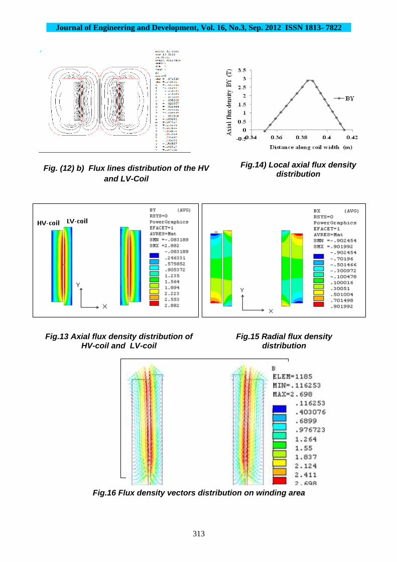
ampere-turn in both side (HV coil and LV coil). As shown in Fig.(12) the axial component of
leakage flux almost include whole area and the Radial component leakage flux only includes
two areas on end winding that their direction is opposite to each other.
The computation results show that along Y direction (Height of coil), the axial flux density
(BY) gradually decreases from the middle to the end of winding. Along X direction(coil
width), the axial flux density linearly decreases from the outer side to the inner side of the LV
winding and linearly decreases from the inner side to outer side of the HV winding as seen in
Fig (13). This tendency of variation can be seen clearly from BY-X curve at the axis of
translational symmetry in Fig.(14). Furthermore the radial flux density at the ends of winding
is much higher than that in the middle of the winding as shown in Fig (15), and the field
vector at two end area of primary and secondary windings are radial and at other area are axial
as shown in Fig (16). The reason of differences between field vectors directions in primary
and secondary windings is opposite current direction in two windings.
Y
X
Fig.11 Output voltage waveform
Journal of Engineering and Development, Vol. 16, No.3, Sep. 2012 ISSN 1813- 7822
313
Fig. (12) b) Flux lines distribution of the HV
and LV-Coil
Fig.13 Axial flux density distribution of HV-coil and LV-coil
Fig.14) Local axial flux density distribution
along coil width
Fig.15 Radial flux density distribution
of HV-coil and LV-coil
Fig.16 Flux density vectors distribution on winding area

Journal of Engineering and Development, Vol. 16, No.3, Sep. 2012 ISSN 1813- 7822
314
Figs. (17) and (18) show the distribution of radial and axial magnetic flux density along the
height of the HV coil.
After the solution of leakage magnetic Field using the finite element method, the leakage
inductance can be calculated from the total magnetic energy. Equation (23) can describe the
Relation of the leakage inductance and the leakage Magnetic field energy, and the magnetic
energy can be calculated from Equations (28) or (29). As is known, the value of leakage
reactance is equal to multiplication of inductance and angular frequency as Equations (31).
Furthermore, the value of leakage reactance in the engineering applications, reactance can
show the percentage of leakage reactance voltage and rated voltage.
Table.3 shows the values of Magnetic energy, leakage inductance and leakage reactance on
primary and secondary windings.
The results obtained from energy method and classical method (conventional design) is
compared with actual test results, as shown in Table.4
Type
windings
Magnetic
energy (J)
Leakage
inductance (mH)
Primary 8.0811 80.85
Secondary 4.2784 0.01815
Table.3. the values of Magnetic energy and leakage
inductance
Fig.17 Radial flux distribution
along center line of HV-coil
Fig.18 Axial flux distribution
along center line of HV-coil

Journal of Engineering and Development, Vol. 16, No.3, Sep. 2012 ISSN 1813- 7822
315
The Leakage reactance value calculated with the use of the 2D FEM model was equal to
3.885%. The classical design methodology resulted equal to 3.82, while the test value of short-
circuit reactance of the study transformer was found equal to 3.94. Therefore, the deviation
between 2D FEM and the test value is equal to 1.39%, while the deviation of the classical
method is equal to 3.04%.
In order to discuss the effect of the MMFs of the adjacent phase on the calculation leakage
reactance at any windings area in another phase, Phase B is considered in two cases:
Case 1- One phase only is excited
Case 2- Three phases of the transformer are excited The comparison between the two case shown in Fig.(19),which shows the distribution of
magnetic flux density in phase(B) in each case. From this figure it is obvious that the
magnitude of magnetic flux density in case(2) is greater than that of case(1) , because the flux
density in each point in coil region is composed of the flux due to the current passing through
phase B and other flux from the adjacent coils. This difference in the components of the flux
density between the two cases will affect the magnitude of the leakage reactance in the coils,
especially on the axial flux component.
Method leakage reactance in
percentage values (%IXL)
Error in respect to
the test values (%)
Energy
method
3.885 1.39%
Classical
method
3.82 3.04%
Test results 3.94 ------
Table.4 Comparison of Energy method results of leakage reactance with test
results
Fig.19 Axial flux distribution along center line of HV-coil in two
cases

Journal of Engineering and Development, Vol. 16, No.3, Sep. 2012 ISSN 1813- 7822
316
The analysis which is done in transformer model when three phases of the transformer are
excited will permit to study the effects of MMF of the adjacent phase and also the effects of
the high level saturation in the lateral limbs.
The obtained results show that the leakage reactance in the case of supplying the transformer
with 3-phase voltage increase by (4.1%) over that when supplied with phase B only. as shown
in Table (5).
8-2 The Results of 3D Solution
The main objective of 3D Static Analysis is to study the distribution of the magnetic flux and
calculation of the leakage reactance values especially in the portion of coil (End Region) out
of the window of core which is not possible to calculate in 2D model.
To perform this type of electromagnetic analysis, the same procedure can be used as in a 2D
static analysis but the 3D FE analysis of transformer model is complex and needs long time to
be solved as compared with 2D analysis.
The distribution of the leakage flux in coil regions is complicated due to the difference in the
direction of the current in the different regions around the coil. This leads to produce
magnetic flux in the three dimensions (BX, BY, BZ). Fig. (20) Shows the distributions of radial
and axial flux density in different Region of HV and LV coil.
Cases of excited leakage reactance in
percentage values (%IXL)
Error in respect to
the test values (%)
Case 1
Phase B only is excited
3.723 5.5 %
Case 2
Three phase are excited
3.885 1.39%
Test value 3.94 ------
Table (5) Comparison between (case1) and (case2) leakage reactance
Results
End
region

Journal of Engineering and Development, Vol. 16, No.3, Sep. 2012 ISSN 1813- 7822
317
From Fig (21) - Fig.(22), it can see that the behavior of flux density are the same as in 2D
analysis, but simple different about the values, due to the effect of Z-component of flux in 3D
analysis. The magnetic energy can be calculated from the product of current density and
vector potential integrated over the volume. The results obtained for the Leakage reactance
are given in Table (5). These results show that the Leakage reactance on the coil region (Side
Region) which is situated in the window of the core are approximately the same as that for
2D model, and they are expected to be more accurate than that of 2D because they include the
z-component of the flux.
Fig.21 Axial flux distribution along Center line of HV-coil
Fig.22 Radial flux distribution along Center line of HV-coil
Fig.20 leakage flux distribution in the different regions around
the coil
c) Axial flux distribution in the Side region
Side
region
Curvature
region
b) Radial flux distribution in the Curvature region
d) Axial flux distribution in the End region and Curvature region
a) Radial flux distribution in the End region

Journal of Engineering and Development, Vol. 16, No.3, Sep. 2012 ISSN 1813- 7822
318
The short-circuit leakage reactance value calculated with the use of the 3D FEM model was
equal to 3.939 and the Test value is equal to 3.94, Therefore, The results are agrees with test
value, and the deviation between 3D FEM and the test value is equal to 0.02% while the
deviation of the classical method is equal to 3.04%. This difference demonstrates the ability
of 3D FEM to accurately predict the Leakage reactance, due to the better representation of the
real transformer geometry.
9-CONCLUSIONS
In the present paper, the classical design methodology and energy method in 2D and 3D FEM
models have been applied for the calculation of the leakage reactance of three-phase, wound
core, distribution transformers. The results of the method were compared to the ones of the
actual test values,
The obtained results have shown that:
The energy method is the more accurate than classical design method because of the results
that obtained from ANSYS in 3D FEM model agrees with test values, the deviation equal to
0.02% as compared with nearly 3.04 % for the results based on classical design.
The 3D FEM model provides higher accuracy in the prediction of the leakage reactance than
2D FEM, with respect to the actual test values, due to the better representation of the
transformer geometry. Also 3D FEM analysis is necessary to compute the magnetic flux (out
of the window) in Curvature and End regions that are not possible with 2D analysis
In order to get accurate results on the calculation leakage reactance, the FEM analysis must be
done in transformer model when three phases of the transformer are excited to take into
account simultaneously both the MMF of the adjacent phase and the effect of saturation in
some branches of limb core.
The paper describes a simple technique for modeling distribution transformer "wound core" in
2D and 3D model
Method leakage reactance in
percentage values
(%IXL)
Error in respect to
the test values
(%)
Energy method
2D Results
3.885 1.39%
Energy method
3D Results
3.9399 0.02%
Classical method 3.82 3.04%
Test results 3.94 ------
Table.5 Comparison of 3D and 2D results of leakage reactance with test
results

Journal of Engineering and Development, Vol. 16, No.3, Sep. 2012 ISSN 1813- 7822
319
These accurate results provide significant economic gains to the transformer manufacturer
like (Diyala Company of Electrical Industries) through reduction of the industrial cycle and
the production cost before manufacturing
10-REFERENCES
[1]A.M. Kashtiban “Finite Element Calculation of Winding Type Effect on Leakage
Flux in Single Phase Shell Type Transformers” Proceedings of the 5th WSEAS
International Conference on Applications of Electrical Engineering, Prague, Czech
Republic, March 12-14, 2006 (pp39-43)
[2]Marina A. Tsili “Advanced design methodology for single and dual voltage wound
core power transformers based on a particular finite element model” Electric Power
Systems Research 76 (2006) 729–741
[3]A. Naderian Jahromi “A Fast Method for Calculation of Transformers Leakage
Reactance using Energy Technique” IJE Transactions B: ApplicationsVol. 16, No. 1,
April 2003
[4] William M. Flanagan “Handbook of Transformer Design and Applications”
Second edition, McGraw-Hill,1992
[5]A. D. Yamkov, "Transformer Design " Mir Publisher, Moscow, 1975
[6]V.N. Mittit “Design of Electrical Machines” fourth edition 1996 ,Published by N.
C. Jain for Standard publishers distributors ,delhi
[7]A.G. kladas, M. P. Papadopulos and J. A. Tegopoulos " Leakage flux and force
calculation on power transformer winding under short-circuit :2D and 3D models
based on the finite element method compared to measurement", IEEE Trans. On,
Magnetics. , vol. 30, No. 5 September 1994
[8] Simon C. Bell and Pat S. Bodger “Power Transformer Deign using Magnetic circuit
theory and Finite Element Analysis-A comparison of Techniques” Presented in
AUPEC 2007, Perth, Western Australia, 9-12 December, 2007
[9] S. Jamali Arand1, K. Abbaszadeh2 “The Study of Magnetic Flux Shunts Effects on
the Leakage Reactance of Transformers via FEM” Majlesi Journal of Electrical
Engineering Vol. 4, No. 3, September 2010
[10]Robert M.Del Vecchio “Transformer Design Principles with Applications to Core-
Form Power Transformers”, CRC PRESS London 2002, Web site at
www.crcpress.com
[11]S.V.Kulkarni and S.A.Khaparde " Transformer Engineering Design and Practice",
Marcel Dekker, Inc, New York • Basel 2005

Journal of Engineering and Development, Vol. 16, No.3, Sep. 2012 ISSN 1813- 7822
320
[12]T. Yun-Qiu & other ," Numerical calculation of short circuit electromagnetic forces
on the transformer winding ", IEEE Trans. On Magnetics. vol.26, No.2, March 1990.
[13] O. W. Andersen, “Transformer leakage flux program based on the finite element
method,” IEEE Trans. Power App. Sys., vol. PAS-92, no. 2, pp.682–689, Mar. 1973.
[14]M.A. TSILI1, A G. KLADAS1” 3D Finite Element and Mixed Finite-Boundary
Element Method for the Magnetic Field Analysis of Power Transformers” Wseas
Transactions ON Circuits and Systems Issue 5,Volume 3, 2004
[15]Pavlos S. Georgilakis “Spotlight on Modern Transformer Design”, Springer,2009
[16]S.Jamali, M. Ardebili, and K. Abbaszadeh “Calculation of short-circuit reactance
and electromagnetic forces in three-phase transformer by finite element method” -
Proceedings of the Eighth International Conference on Publication Electrical
Machines and Systems, 2005. (ICEMS 2005), pp. 1725- 1730 - Vol. 3.
[17]GUEMES-ALONSO, J.A. - “A new method for calculating of leakage reactances
and iron losses in transformers” - Proceedings of the Fifth International Conference
on Electrical Machines and Systems, 2001. (ICEMS 2001), Vol: 1, 18-20 Aug. 2001,
pgs: 178-181
[18]KASHTIBAN, A.M.; VAHEDI, A.; HALVAEI, A.; - “Investigation of winding
type effect on leakage flux of single phase shell type transformer using FEM” -
Proceedings of the Eighth International Conference on Electrical Machines and
Systems, 2005. (ICEMS 2005), Vol: 3, Sept. 2005, pgs:1755 - 1758.
[19] "Design Calculation Sheet of 400 KVA distribution transformer “Mitsubishi
Electric Corporation, 1983.
[20] Martin J. Heathcote, CEng, FIEE "The J&P Transformer ", Twelfth edition,
[21] Marina A. TSILI ,Antonios G. KLADAS “Wound Core Power Transformer
Design: Classical Methodology and Advanced Magnetic Field Analysis Techniques”
Advanced Research Workshop on Modern Transformers. 28 -30 October 2004. Vigo
– Spain
[22]"Design standard of distribution transformer" Mitsubishi Electric Corporation,
1983
[23] J. D. Lavers “Electromagnetic Field Computation in power Engineering” IEEE
Trans. On, Magnetics, vol. 29, No. 6 ,November 1993
[24] Documentation for ANSYS11
[25] P.Silvester,A. Kourad, "Analysis of transformer leakage phenomena by high order
finite element", IEEE Trans. PAS., vol. 92,pp.,1843-1855, 1973
[26]Jan Sykulski, "Field Simulation an Aid to Machine Design: The State of the Art",
IEEE 2006,University of Southampton, United Kingdom