limitorque b320 series - flowserve
TRANSCRIPT
Experience In Motion
Limitorque B320 SeriesBevel Gear Operators
Rugged and dependable for manual or motorized valve control applications
2
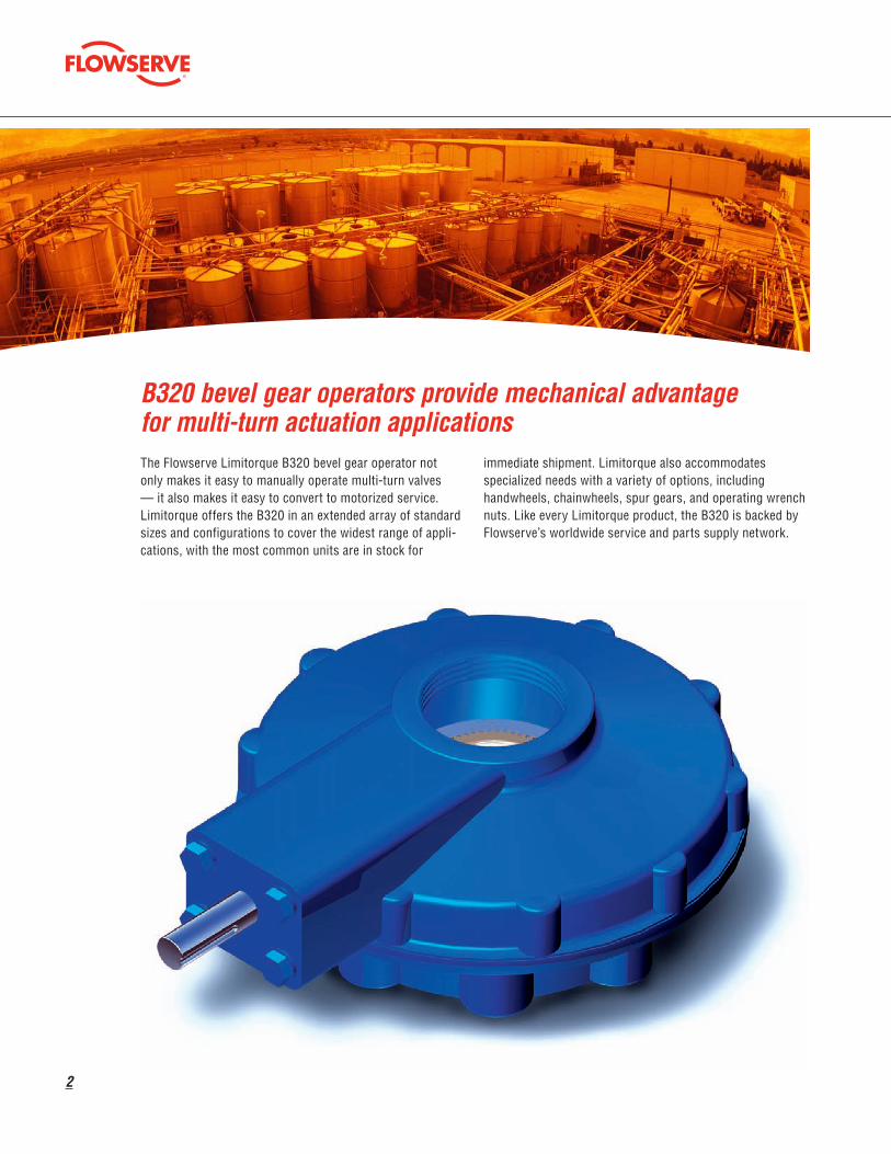
B320 bevel gear operators provide mechanical advantage for multi-turn actuation applicationsThe Flowserve Limitorque B320 bevel gear operator not only makes it easy to manually operate multi-turn valves — it also makes it easy to convert to motorized service. Limitorque offers the B320 in an extended array of standard sizes and configurations to cover the widest range of appli-cations, with the most common units are in stock for
immediate shipment. Limitorque also accommodates specialized needs with a variety of options, including handwheels, chainwheels, spur gears, and operating wrench nuts. Like every Limitorque product, the B320 is backed by Flowserve’s worldwide service and parts supply network.

flowserve.com
3
The B320 offers torque ranges up to 8,000 ft-lb (10,856 N m) and thrust capacities to 325,000 lb (1445 kN), for any application demanding a bevel gear operator with superior
strength and accuracy. It is most commonly used with sluice/slide gates, gate valves, and globe valves.
B320 features: built for reliable valve control — whether manual or motorized
Available options for the B320 operator include:
Flowserve Limitorque has designed the B320 to be configured to each customer’s needs. Choose an optional handwheel for manual actuation. Add a spur gear attachment for greater mechanical advantage. And when manual operation simply
isn’t practical, just couple the B320 with one of Limitorque’s electric actuators for an economical, motorized, multi-turn package.
Spur gear attachments for reduction of input torque
Handwheels and chainwheels
Easily adaptable for other applications
Direct mounting to an electric valve actuator
4
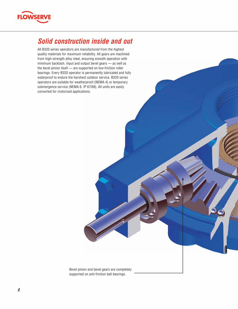
Solid construction inside and out All B320 series operators are manufactured from the highest quality materials for maximum reliability. All gears are machined from high-strength alloy steel, ensuring smooth operation with minimum backlash. Input and output bevel gears — as well as the bevel pinion itself — are supported on low-friction roller bearings. Every B320 operator is permanently lubricated and fully waterproof to endure the harshest outdoor service. B320 series operators are suitable for weatherproof (NEMA 4) or temporary submergence service (NEMA 6, IP 67/68). All units are easily converted for motorized applications.
Bevel pinion and bevel gears are completely supported on anti-friction ball bearings.

flowserve.com
5
Rugged cast iron enclosure meets the most severe environmental conditions.
Machine-generated gearing assures minimum backlash and smooth operation.
Splined bronze alloy stem nut is removable for threading or custom bore and key.
6
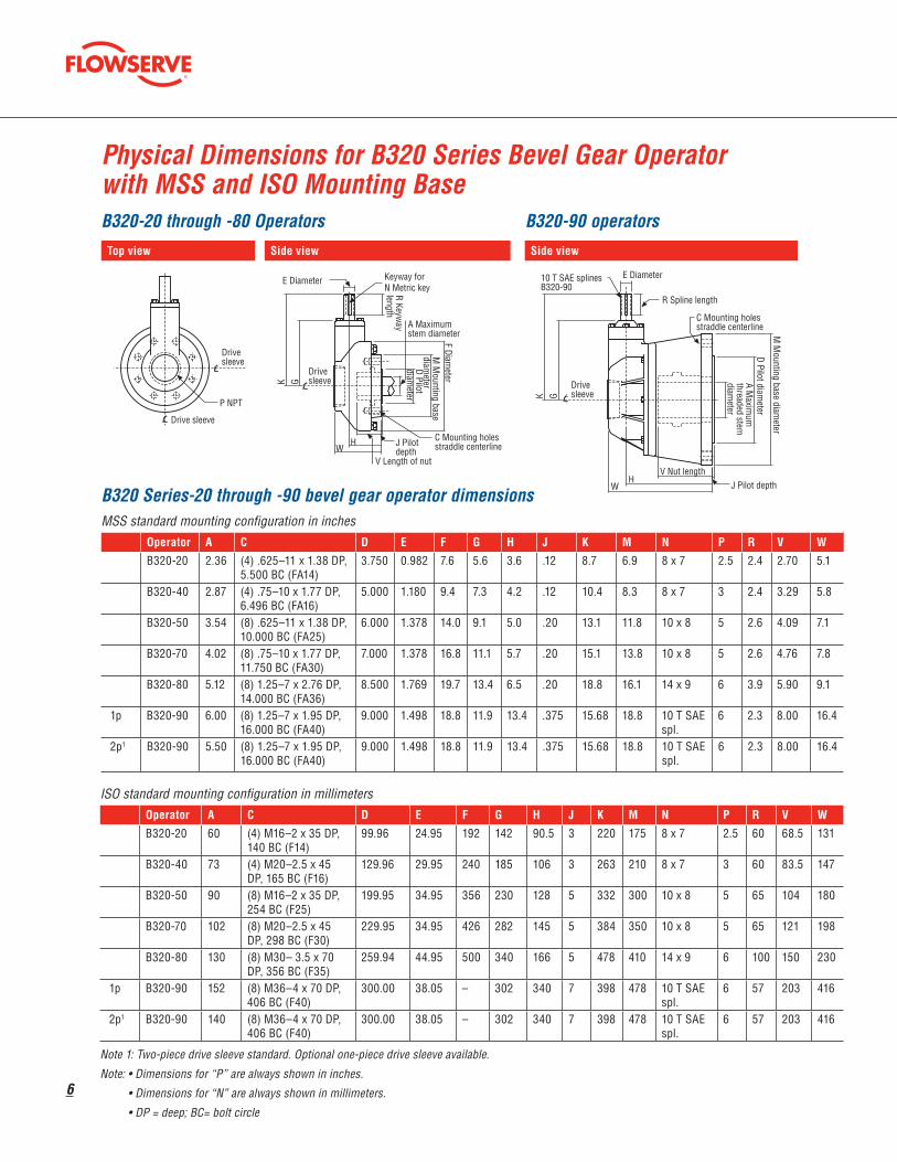
Physical Dimensions for B320 Series Bevel Gear Operator with MSS and ISO Mounting Base
Top view
Drivesleeve
Drive sleeve
P NPT
D Pilotdiam
eter
M M
ounting basediam
eter
J Pilotdepth
C Mounting holesstraddle centerline
Drivesleeve
F Diameter
V Length of nut
Keyway for N Metric key
HW
A Maximumstem diameter
GK
E Diameter
R Keyway
length
Drivesleeve
D Pilot diameter
C Mounting holesstraddle centerline
10 T SAE splinesB320-90
GK
E Diameter
R Spline length
WH
J Pilot depthV Nut length
M M
ounting base diameter
A Maxim
umthreaded stemdiam
eter
Side view
Drivesleeve
Drive sleeve
P NPT
D Pilotdiam
eter
M M
ounting basediam
eter
J Pilotdepth
C Mounting holesstraddle centerline
Drivesleeve
F Diameter
V Length of nut
Keyway for N Metric key
HW
A Maximumstem diameter
GKE Diameter
R Keyway
length
Drivesleeve
D Pilot diameter
C Mounting holesstraddle centerline
10 T SAE splinesB320-90
GK
E Diameter
R Spline length
WH
J Pilot depthV Nut length
M M
ounting base diameter
A Maxim
umthreaded stemdiam
eter
Side view
Drivesleeve
Drive sleeve
P NPT
D Pilotdiam
eter
M M
ounting basediam
eterJ Pilotdepth
C Mounting holesstraddle centerline
Drivesleeve
F Diameter
V Length of nut
Keyway for N Metric key
HW
A Maximumstem diameter
GKE Diameter
R Keyway
length
Drivesleeve
D Pilot diameter
C Mounting holesstraddle centerline
10 T SAE splinesB320-90
GK
E Diameter
R Spline length
WH
J Pilot depthV Nut length
M M
ounting base diameter
A Maxim
umthreaded stemdiam
eter
B320-20 through -80 Operators B320-90 operators
B320 Series-20 through -90 bevel gear operator dimensionsMSS standard mounting configuration in inches
Operator A C D E F G H J K M N P R V W
B320-20 2.36 (4) .625–11 x 1.38 DP, 5.500 BC (FA14)
3.750 0.982 7.6 5.6 3.6 .12 8.7 6.9 8 x 7 2.5 2.4 2.70 5.1
B320-40 2.87 (4) .75–10 x 1.77 DP, 6.496 BC (FA16)
5.000 1.180 9.4 7.3 4.2 .12 10.4 8.3 8 x 7 3 2.4 3.29 5.8
B320-50 3.54 (8) .625–11 x 1.38 DP, 10.000 BC (FA25)
6.000 1.378 14.0 9.1 5.0 .20 13.1 11.8 10 x 8 5 2.6 4.09 7.1
B320-70 4.02 (8) .75–10 x 1.77 DP, 11.750 BC (FA30)
7.000 1.378 16.8 11.1 5.7 .20 15.1 13.8 10 x 8 5 2.6 4.76 7.8
B320-80 5.12 (8) 1.25–7 x 2.76 DP, 14.000 BC (FA36)
8.500 1.769 19.7 13.4 6.5 .20 18.8 16.1 14 x 9 6 3.9 5.90 9.1
1p B320-90 6.00 (8) 1.25–7 x 1.95 DP, 16.000 BC (FA40)
9.000 1.498 18.8 11.9 13.4 .375 15.68 18.8 10 T SAE spl.
6 2.3 8.00 16.4
2p1 B320-90 5.50 (8) 1.25–7 x 1.95 DP, 16.000 BC (FA40)
9.000 1.498 18.8 11.9 13.4 .375 15.68 18.8 10 T SAE spl.
6 2.3 8.00 16.4
ISO standard mounting configuration in millimetersOperator A C D E F G H J K M N P R V W
B320-20 60 (4) M16–2 x 35 DP, 140 BC (F14)
99.96 24.95 192 142 90.5 3 220 175 8 x 7 2.5 60 68.5 131
B320-40 73 (4) M20–2.5 x 45 DP, 165 BC (F16)
129.96 29.95 240 185 106 3 263 210 8 x 7 3 60 83.5 147
B320-50 90 (8) M16–2 x 35 DP, 254 BC (F25)
199.95 34.95 356 230 128 5 332 300 10 x 8 5 65 104 180
B320-70 102 (8) M20–2.5 x 45 DP, 298 BC (F30)
229.95 34.95 426 282 145 5 384 350 10 x 8 5 65 121 198
B320-80 130 (8) M30– 3.5 x 70 DP, 356 BC (F35)
259.94 44.95 500 340 166 5 478 410 14 x 9 6 100 150 230
1p B320-90 152 (8) M36–4 x 70 DP, 406 BC (F40)
300.00 38.05 – 302 340 7 398 478 10 T SAE spl.
6 57 203 416
2p1 B320-90 140 (8) M36–4 x 70 DP, 406 BC (F40)
300.00 38.05 – 302 340 7 398 478 10 T SAE spl.
6 57 203 416
Note 1: Two-piece drive sleeve standard. Optional one-piece drive sleeve available.
Note: • Dimensions for “P” are always shown in inches.
• Dimensions for “N” are always shown in millimeters.
• DP = deep; BC= bolt circle
flowserve.com
7
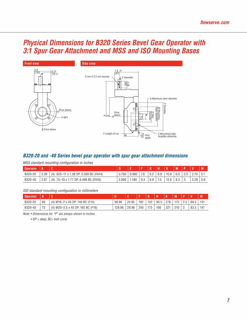
Physical Dimensions for B320 Series Bevel Gear Operator with 3:1 Spur Gear Attachment and MSS and ISO Mounting BasesFront view
Drive sleeve
Drive sleeve
P NPT
5.9(150) 0.75
(19.1)
Pilotdepth
C Mounting holesstraddle centerline
Drivesleeve
8 mm X 3.5 mm keyway
D Pilotdiam
eter
V Length of nut
M M
ountingbase diam
eter
F Diameter
E Diameter
K G
2.36(60)
H
A Maximum stem diameter
W
1.6(41)
.12(3)
Side view
Drive sleeve
Drive sleeve
P NPT
5.9(150) 0.75
(19.1)
Pilotdepth
C Mounting holesstraddle centerline
Drivesleeve
8 mm X 3.5 mm keyway
D Pilotdiam
eter
V Length of nut
M M
ountingbase diam
eter
F Diameter
E Diameter
K G
2.36(60)
H
A Maximum stem diameter
W
1.6(41)
.12(3)
B320-20 and -40 Series bevel gear operator with spur gear attachment dimensionsMSS standard mounting configuration in inchesOperator A C D E F G H K M P V W
B320-20 2.36 (4) .625–11 x 1.38 DP, 5.500 BC (FA14) 3.750 0.982 7.6 5.2 6.9 10.9 6.9 2.5 2.70 5.1
B320-40 2.87 (4) .75–10 x 1.77 DP, 6.496 BC (FA16) 5.000 1.180 9.4 6.9 7.5 12.6 8.3 3 3.29 5.8
ISO standard mounting configuration in millimetersOperator A C D E F G H K M P V W
B320-20 60 (4) M16–2 x 35 DP, 140 BC (F14) 99.96 24.95 192 132 90.5 278 175 2.5 68.5 131
B320-40 73 (4) M20–2.5 x 45 DP, 165 BC (F16) 129.96 29.96 240 175 106 321 210 3 83.5 147
Note: • Dimensions for “P” are always shown in inches.
• DP = deep; BC= bolt circle
8
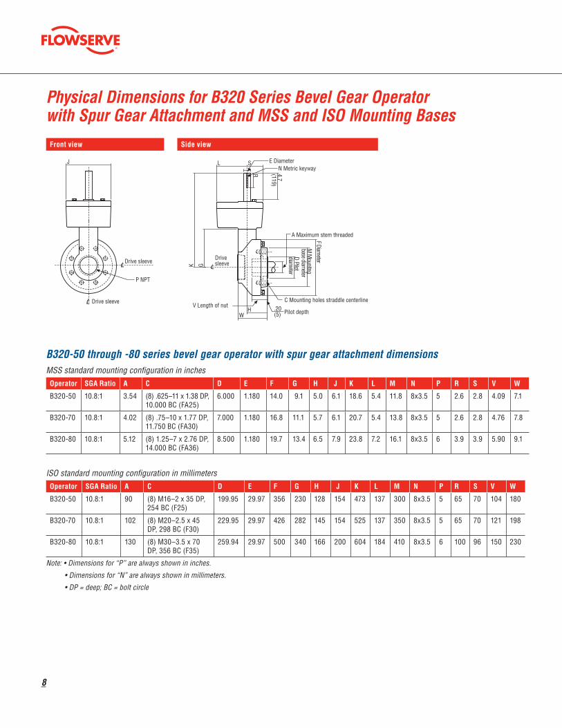
Physical Dimensions for B320 Series Bevel Gear Operator with Spur Gear Attachment and MSS and ISO Mounting BasesFront view
Drive sleeve
Drive sleeve
P NPT
J
.20 Pilot depth (5)
C Mounting holes straddle centerline
Drivesleeve
V Length of nut
N Metric keyway
D Pilot
diameter
H
M M
ounitngbase diam
eter
F Diameter
E Diameter
W
K G
4.7(119)
A Maximum stem threaded
L S
R
Side view
Drive sleeve
Drive sleeve
P NPT
J
.20 Pilot depth (5)
C Mounting holes straddle centerline
Drivesleeve
V Length of nut
N Metric keyway
D Pilot
diameter
H
M M
ounitngbase diam
eter
F Diameter
E Diameter
W
K G
4.7(119)
A Maximum stem threaded
L S
R
B320-50 through -80 series bevel gear operator with spur gear attachment dimensions MSS standard mounting configuration in inchesOperator SGA Ratio A C D E F G H J K L M N P R S V W
B320-50 10.8:1 3.54 (8) .625–11 x 1.38 DP, 10.000 BC (FA25)
6.000 1.180 14.0 9.1 5.0 6.1 18.6 5.4 11.8 8x3.5 5 2.6 2.8 4.09 7.1
B320-70 10.8:1 4.02 (8) .75–10 x 1.77 DP, 11.750 BC (FA30)
7.000 1.180 16.8 11.1 5.7 6.1 20.7 5.4 13.8 8x3.5 5 2.6 2.8 4.76 7.8
B320-80 10.8:1 5.12 (8) 1.25–7 x 2.76 DP, 14.000 BC (FA36)
8.500 1.180 19.7 13.4 6.5 7.9 23.8 7.2 16.1 8x3.5 6 3.9 3.9 5.90 9.1
ISO standard mounting configuration in millimetersOperator SGA Ratio A C D E F G H J K L M N P R S V W
B320-50 10.8:1 90 (8) M16–2 x 35 DP, 254 BC (F25)
199.95 29.97 356 230 128 154 473 137 300 8x3.5 5 65 70 104 180
B320-70 10.8:1 102 (8) M20–2.5 x 45 DP, 298 BC (F30)
229.95 29.97 426 282 145 154 525 137 350 8x3.5 5 65 70 121 198
B320-80 10.8:1 130 (8) M30–3.5 x 70 DP, 356 BC (F35)
259.94 29.97 500 340 166 200 604 184 410 8x3.5 6 100 96 150 230
Note: • Dimensions for “P” are always shown in inches.
• Dimensions for “N” are always shown in millimeters.
• DP = deep; BC = bolt circle

flowserve.com
9
Physical Dimensions for B320 Series Bevel Gear Operator with 17.5:1 Spur Gear Attachment and MSS and ISO Mounting BasesFront view
D Pilot diameter
M Mounting base diameter
J Pilot depth
3.6(90) 1.25
(31.8) Effectivespline length
1.373(34.87) Diameter6T SAE splines
5.50(139) Maximum stemdiameter
4.0(102)
14.8(376)
H
11.6(295)
Z
21.9(556)
“6” NPT
Mounting base
“A”relocatedinput shaft
Driv
esl
eeve
C Optional input shaft
Drivesleeve
C Mounting holesstraddle centerline
Driv
esl
eeve
C
Driv
esl
eeve
W
C
C
V Le
ngth
of n
ut
Side view
D Pilot diameter
M Mounting base diameter
J Pilot depth
3.6(90) 1.25
(31.8) Effectivespline length
1.373(34.87) Diameter6T SAE splines
5.50(139) Maximum stemdiameter
4.0(102)
14.8(376)
H
11.6(295)
Z
21.9(556)
“6” NPT
Mounting base
“A”relocatedinput shaft
Driv
esl
eeve
C Optional input shaft
Drivesleeve
C Mounting holesstraddle centerline
Driv
esl
eeve
C
Driv
esl
eeve
W
C
C
V Le
ngth
of n
ut
B320-90 series bevel gear operator with spur gear attachment dimensionsMSS standard mounting configuration in inchesOperator SGA Ratio C D H J M V W Z
B320-90 17.5:1 (8) 1.25–7 x 1.95 DP, 16.00 BC (FA40) 9.000 (+.000/-.002) 17.4 .375 18.8 8.00 16.4 3.7
ISO standard mounting configuration in millimetersOperator SGA Ratio C D H J M V W Z
B320-90 17.5:1 (8) M36–4 x 70 DP, 406 BC (F40) 300 (+ .00/-.05) 442 7 475 203 416 94
Note: • Inch tap only available.
• DP = deep
* BC = bolt circle
10
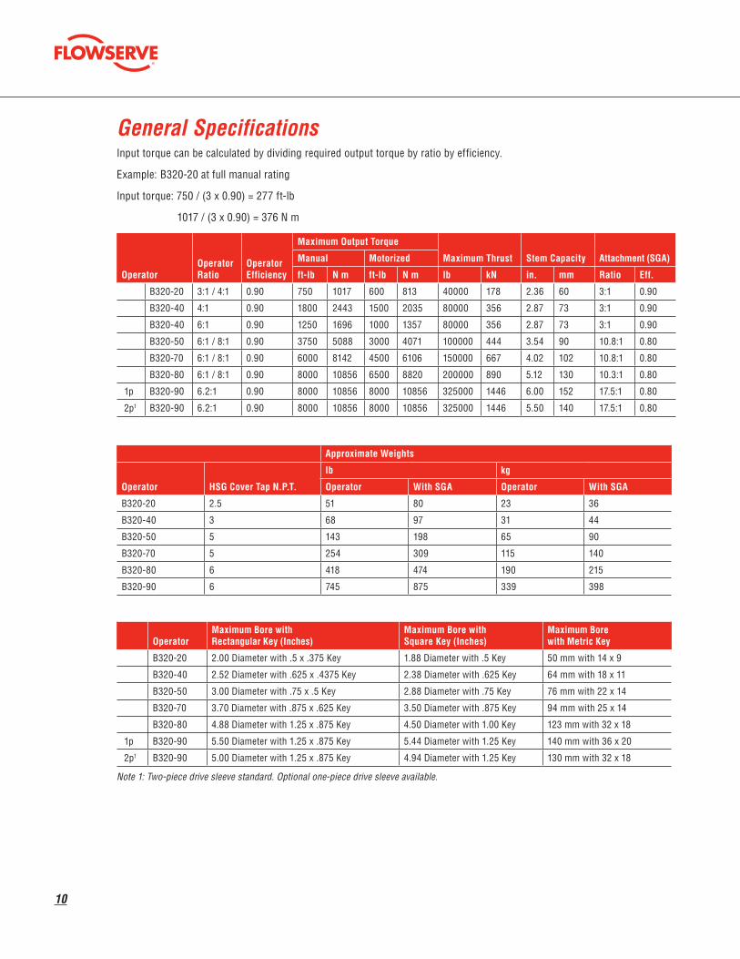
General SpecificationsInput torque can be calculated by dividing required output torque by ratio by efficiency.
Example: B320-20 at full manual rating
Input torque: 750 / (3 x 0.90) = 277 ft-lb
1017 / (3 x 0.90) = 376 N m
Operator Operator Ratio
Operator Efficiency
Maximum Output Torque
Maximum Thrust Stem Capacity Attachment (SGA)Manual Motorized
ft-lb N m ft-lb N m lb kN in. mm Ratio Eff.
B320-20 3:1 / 4:1 0.90 750 1017 600 813 40000 178 2.36 60 3:1 0.90
B320-40 4:1 0.90 1800 2443 1500 2035 80000 356 2.87 73 3:1 0.90
B320-40 6:1 0.90 1250 1696 1000 1357 80000 356 2.87 73 3:1 0.90
B320-50 6:1 / 8:1 0.90 3750 5088 3000 4071 100000 444 3.54 90 10.8:1 0.80
B320-70 6:1 / 8:1 0.90 6000 8142 4500 6106 150000 667 4.02 102 10.8:1 0.80
B320-80 6:1 / 8:1 0.90 8000 10856 6500 8820 200000 890 5.12 130 10.3:1 0.80
1p B320-90 6.2:1 0.90 8000 10856 8000 10856 325000 1446 6.00 152 17.5:1 0.80
2p1 B320-90 6.2:1 0.90 8000 10856 8000 10856 325000 1446 5.50 140 17.5:1 0.80
Approximate Weights
Operator HSG Cover Tap N.P.T.
lb kg
Operator With SGA Operator With SGA
B320-20 2.5 51 80 23 36
B320-40 3 68 97 31 44
B320-50 5 143 198 65 90
B320-70 5 254 309 115 140
B320-80 6 418 474 190 215
B320-90 6 745 875 339 398
OperatorMaximum Bore with Rectangular Key (Inches)
Maximum Bore with Square Key (Inches)
Maximum Bore with Metric Key
B320-20 2.00 Diameter with .5 x .375 Key 1.88 Diameter with .5 Key 50 mm with 14 x 9
B320-40 2.52 Diameter with .625 x .4375 Key 2.38 Diameter with .625 Key 64 mm with 18 x 11
B320-50 3.00 Diameter with .75 x .5 Key 2.88 Diameter with .75 Key 76 mm with 22 x 14
B320-70 3.70 Diameter with .875 x .625 Key 3.50 Diameter with .875 Key 94 mm with 25 x 14
B320-80 4.88 Diameter with 1.25 x .875 Key 4.50 Diameter with 1.00 Key 123 mm with 32 x 18
1p B320-90 5.50 Diameter with 1.25 x .875 Key 5.44 Diameter with 1.25 Key 140 mm with 36 x 20
2p1 B320-90 5.00 Diameter with 1.25 x .875 Key 4.94 Diameter with 1.25 Key 130 mm with 32 x 18
Note 1: Two-piece drive sleeve standard. Optional one-piece drive sleeve available.

flowserve.com
11
This page is left intentionally blank.
flowserve.com
To find your local Flowserve representative, visit www.flowserve.com or call USA 1 800 225 6989
Flowserve CorporationFlow Control
United StatesFlowserve Limitorque5114 Woodall Road, P.O. Box 11318Lynchburg, VA 24506-1318Phone: 434-528-4400Facsimile: 434-845-9736
EnglandFlowserve LimitorqueEuro HouseAbex RoadNewburyBerkshire, RG14 5EYUnited KingdomPhone: 44-1-635-46999Facsimile: 44-1-635-36034
JapanLimitorque – Nippon Gear Co., Ltd.Asahi-Seimei Bldg. 4th Floor1-11-11 Kita-Saiwai, Nishi-KuYokohama-Shi, (220-0004)JapanPhone: 81-45-326-2065Facsimile: 81-45-320-5962
CanadaFlowserve Limitorque120 Vinyl CourtWoodbridge, Ontario L4L 4A3CanadaPhone 905-856-4565Fax 905-856-7905
SingaporeLimitorque Asia, Pte., Ltd.12, Tuas Avenue 20Singapore 638824Phone: 65-6868-4628Facsimile: 65-6862-4940
IndiaFlowserve Limitorque423 Jaina Towers IIDistrict Centre, JanakpuriNew Delhi, India 110058Phone: 91-11-2561-4486
ChinaLimitorque Beijing PTE LTDRM A1/A222/F, East Area, Hanwei PlazaNo. 7 Guanghua RoadChaoyang DistrictBeijing 100004People's Republic of ChinaPhone: 86-10-5921-0606Facsimile: 86-10-6561-2702
FCD LMENBR3200-03 12-09 Printed in USA.
Flowserve Corporation has established industry leadership in the design and manufacture of its products. When properly selected, this Flowserve product is designed to perform its intended function safely during its useful life. However, the purchaser or user of Flowserve products should be aware that Flowserve products might be used in numerous applications under a wide variety of industrial service conditions. Although Flowserve can (and often does) provide general guidelines, it cannot provide specific data and warnings for all possible applications. The purchaser/user must therefore assume the ultimate responsibility for the proper sizing and selection, installation, operation, and maintenance of Flowserve products. The purchaser/user should read and understand the Installation Operation Maintenance (IOM) instructions included with the product, and train its employees and contractors in the safe use of Flowserve products in connection with the specific application.
While the information and specifications contained in this literature are believed to be accurate, they are supplied for informative purposes only and should not be considered certified or as a guarantee of satisfactory results by reliance thereon. Nothing contained herein is to be construed as a warranty or guarantee, express or implied, regarding any matter with respect to this product. Because Flowserve is continually improving and upgrading its product design, the specifications, dimensions and information contained herein are subject to change without notice. Should any question arise concerning these provisions, the purchaser/user should contact Flowserve Corporation at any one of its worldwide operations or offices.
© 2009 Flowserve Corporation, Irving, Texas, USA. Flowserve is a registered trademark of Flowserve Corporation.
To find your local Limitorque representative:visit www.limitorque.com.