user instructions - flowserve · user instructions quick mount and start instructions limitorque qx...
TRANSCRIPT
Experience In Motion
USER INSTRUCTIONS
Quick Mount and Start
Instructions
Limitorque QX Electronic ActuatorFCD LMENIM3313-02 – 03/12
Limitorque QX Electronic Actuator FCD LMENIM3313-02 – 03/12
2
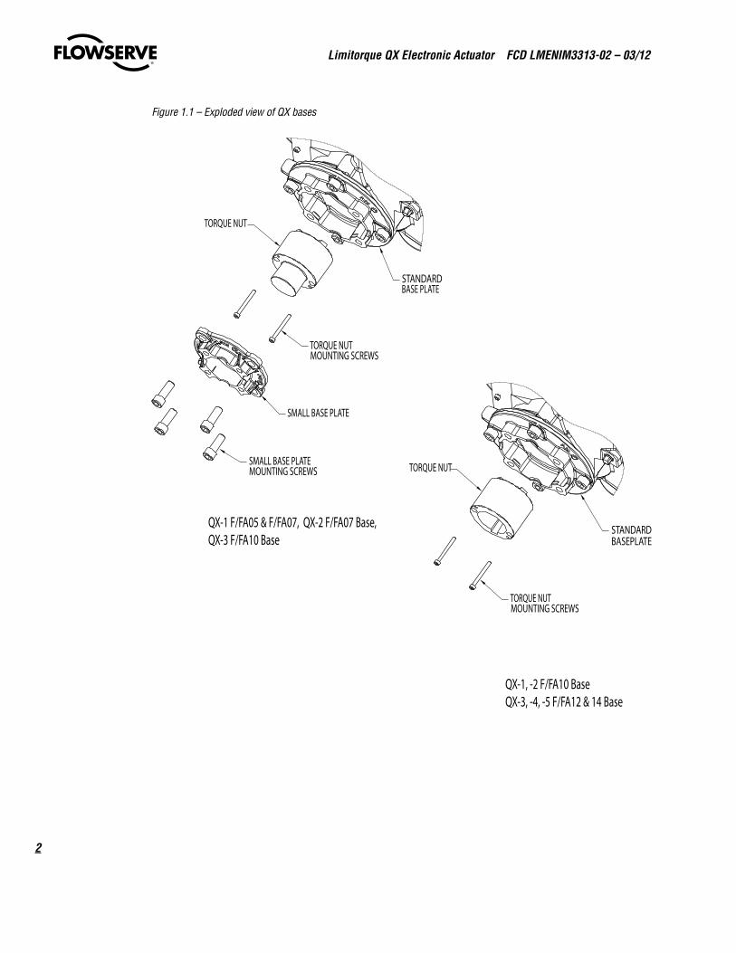
STANDARD BASEPLATE
TORQUE NUT
TORQUE NUT MOUNTING SCREWS
STANDARD BASE PLATE
TORQUE NUT
TORQUE NUT MOUNTING SCREWS
SMALL BASE PLATE
SMALL BASE PLATE MOUNTING SCREWS
QX-1 F/FA05 & F/FA07, QX-2 F/FA07 Base, QX-3 F/FA10 Base
QX-1, -2 F/FA10 Base QX-3, -4, -5 F/FA12 & 14 Base
STANDARD BASEPLATE
TORQUE NUT
TORQUE NUT MOUNTING SCREWS
STANDARD BASE PLATE
TORQUE NUT
TORQUE NUT MOUNTING SCREWS
SMALL BASE PLATE
SMALL BASE PLATE MOUNTING SCREWS
QX-1 F/FA05 & F/FA07, QX-2 F/FA07 Base, QX-3 F/FA10 Base
QX-1, -2 F/FA10 Base QX-3, -4, -5 F/FA12 & 14 Base
Figure 1.1 – Exploded view of QX bases
3
Limitorque QX Electronic Actuator FCD LMENIM3313-02 – 03/12
flowserve.com
1 Quick Mount
1.1 Preparing the Stem NutThe QX has two (2) basic base designs:
• Torque-only (90º) operation• Multi-turn operation (up to 20 multi-turn rotations – 7200° total)
Torque Applications
Standard B4/B4E BaseThe standard QX actuator base is the stem nut for torque-only. It includes a mounting plate and steel torque nut, which may be machined to fit a valve or gearbox. A B4E torque nut can be provided and may be installed to allow for extended stem acceptance.
Table 1 – Available QX Flanges
QX-1 QX-2 QX-3 QX-4 QX-5
Flange 1ISO 5210 F05/F07 F07 F10 N/A N/A
MSS SP-102 FA05/07 FA07 FA10 N/A N/A
Flange 2
ISO 5210 F10 F10 F12 (OPT)F14 (STD)
F12 (OPT)F14 (STD)
F14
MSS SP-102 FA10 (STD) FA10 (STD) FA12 (OPT)FA14 (STD)
FA12 (OPT)FA14 (STD)
FA14 (STD)
Limitorque QX Electronic Actuator FCD LMENIM3313-02 – 03/12
4
Disassembly – Flange 11. Remove base plate mounting screws and small base plate.
2. Remove the two torque nut mounting screws and remove the torque nut.
3. Machine the torque nut to suit the valve stem or gearbox input shaft. Ensure sufficient clearance for a smooth, sliding fit.
Disassembly – Flange 21. Remove the two torque nut mounting screws and remove the torque nut.
2. Machine the torque nut to suit the valve stem or gearbox input shaft. Ensure sufficient clearance for a smooth, sliding fit.
Reassembly1. Clean the torque nut thoroughly and lightly grease.
2. Replace the torque nut in the drive sleeve. Ensure the torque nut meshes with the drive lugs.
3. Reinstall the torque nut mounting screws.
1.2 Mechanical Installation onto Valve or GearboxBefore installing the actuator onto a valve or gearbox, check the following to ease installation:
• Verify that mounting flange is suited dimensionally to mate with the actuator base. Ensure that it is perpendicular to the valve stem.
• Ensure the stem nut mates with the valve stem or input shaft. Keyed or splined shafts should exhibit a smooth, sliding fit with the key installed.
• Ensure there is adequate engagement of the stem nut with the valve stem or input shaft when mounted. Generally, the minimum length of engagement is 1.5 times the diameter of the stem.
• Ensure that the valve stem is not too long such that it bottoms out on the QX drive sleeve.
• Verify that mounting studs or bolts are the correct length to suit the thickness of the mounting plate.
• Verify hardware specifications for English style:
• Socket head cap screw per ASTM A 574 and ANSI 18.3.
• Hex head cap screw per SAE J429 Grade 5.
• Verify hardware specifications for metric style: hex and socket head cap screws per Property Class 12.9.
• Clean and lubricate the valve stem or input shaft.
• Ensure adequate lifting facilities and slings are available at the installation site.
NOTE: Do not use the handwheel to lift the actuator.
1. Place the actuator at mid position halfway between the two mechanical stops. This can be done by turning the handwheel until one stop is encountered, then turning the handwheel in the opposite direction to reach the other stop while counting the turns required for full stroke. Then turn the handwheel in the opposite direction again half the number of turns to achieve mid position.
2. Place the valve in mid stroke position. Select the QX position based on the lugs on the torque nut and the slot in the drive sleeve. Install the torque nut and place the QX on the valve. Secure the QX to the valve.
3. The QX actuator is now ready for startup.
5
Limitorque QX Electronic Actuator FCD LMENIM3313-02 – 03/12
flowserve.com
2 Quick Start
Quick Start provides step-by-step instructions for commissioning each QX actuator. These instructions are for the following:
• Position limits calibration – can be performed one of two ways:
1. Electrical operation: See Section 2.1.2, Electrical Operation Feature.
2. Handwheel operation: See Section 2.1.3, Handwheel Operation Feature.
• DDC operation: See Section 2.2, DDC Option.
When these Quick Start instructions are complete, the position limits will be set and the actuator will be ready for normal operation.
NOTE: The actuator has been configured with all customer-specified parameters and no further calibration should be necessary. If full valve data was not provided when ordering, or if changes are needed for parameters, see LMENIM3306, QX Actuator Installation, Operation and Maintenance Manual.
NOTE: Units are shipped with default operating time values based on unit size:
QX-1: 5-20 sec, default 15 sec
QX-2: 8-30 sec, default 30 sec
QX-3: 15-60 sec, default 60 sec
QX-4: 30-120 sec, default 60 sec
QX-5: 60-120 sec, default 60 sec
These times are based on a 90° open to close span.
The operating time can be set as desired by following the instructions in document LMENIM3306, QX Actuator Instruction, Operation and Maintenance Manual.
Limitorque QX Electronic Actuator FCD LMENIM3313-02 – 03/12
6
2.1 Calibrate Position Limits1. Confirm that the QX actuator is correctly installed on the valve as described in Section 1.
2. Refer to the nameplate for the correct main power supply voltage. Switch on the main power to the unit.
3. Turn the red knob to the “STOP” position. The “SET UP ENGLISH?” message will be displayed, select “YES”. The “SET CLOSE POSITION LIMIT?” message will then be displayed. Proceed with setting the open and close limits of the valve.
4. Calibrate end position limits one of two ways:
• Electrically,usingthecontrolpanel.SeeSection2.1.1,ElectricalOperationFeature.
• Manually,usingthehandwheel.SeeSection2.1.2,HandwheelOperationFeature.
Once the position limits have been set, the LCD message will indicate the valve position as a percentage of the valve opening.
While setting limit switches, place the red selector knob in the “LOCAL” position to permit the actuator to run open or closed in push-to-run mode (inching) only.
a CAUTION: Extreme care must be taken as the valve approaches its end position.
The unit will not function with the red selector knob in the “REMOTE” position until both limit switches are set.
The existing configuration of the actuator/valve parameters may be viewed by entering the “SETUP” mode.
2.1.1 Electrical Operation FeatureThis feature allows for quick and simple calibration. From a virgin startup, the “SET CLOSE POSITION LIMIT?” message will be displayed once the setup language has been selected.
NOTE: Refer to Figure 2.1 – Electrical operation as a guide during setup
a CAUTION: Do not adjust close stop while stop is loaded. It is highly recommended that the stops be turned until they are almost removed from the housing before setting the limits. Once the limits have been set, then the stops maybe tightened. Refer to Figure 2.3.
Closed Position Limit
1. “SET CLOSE POSITION LIMIT?” is displayed on the LCD.
2. Select “YES.” The “CLOSE VALVE - OK?” message is displayed.
3. Switch the actuator to “LOCAL” control and use the open/close switch to position the valve to the desired closed position.
4. Back out the close stop if needed. First loosen the screw securing the stop then move stop.
NOTE: Do not adjust close stop while stop is loaded.
5. When the valve is in the desired position, switch the actuator back to “STOP” and select “YES” again. The LCD will read “SAVE CLOSE LIMIT OK?”
6. Select “YES” if the valve’s close limit position is correct. The close position limit is set.
7. Turn the close stop against the drive sleeve, then back off the close stop from the drive sleeve approximately 0.5 to 1.5 turns, ensuring the stop does not contact the drive sleeve.
7
Limitorque QX Electronic Actuator FCD LMENIM3313-02 – 03/12
flowserve.com
a CAUTION: Do not adjust close stop while stop is loaded. It is highly recommended that the stops be turned until they are almost removed from the housing before setting the limits. Once the limits have been set, then the stops maybe tightened. Refer to Figure 2.3.
Open Position Limit
8. “SET OPEN POSITION LIMIT?” is displayed on the LCD.
9. Select “YES.” The “OPEN VALVE - OK?” message is displayed.
10. Switch the actuator to “LOCAL” control and use the open/close switch to position the valve to the desired open position.
11. Back out the open stop if needed. First loosen the screw securing the stop then move stop.
NOTE: Do not adjust open stop while stop is loaded.
12. When the valve is in the desired position, switch the actuator back to “STOP” and select “YES” again. The LCD will read “SAVE OPEN LIMIT OK?”
13. Select “YES” if the valve’s open position limit is correct. The open position limit is set.
14. Turn the open stop against the drive sleeve, then back off the open stop from the drive sleeve approximately 0.5 to 1.5 turns, ensuring the stop does not contact the drive sleeve.
15. Once the limits have been set, electronically cycle the valve open and closed. While at each respective limit of travel and in the motionless condition, reconfirm that the stop does not contact the drive sleeve. To confirm, rotate the stop freely back and forth, encountering only O-ring drag. If the drive sleeve has not been loaded against the stop, secure the stop with screw to lock it in place. If the stop is loaded by the drive sleeve, the stop must be backed away further from the drive sleeve. If stop was in contact with the drive sleeve repeat Step 15 from the beginning. There must be no load on the drive sleeve before adjusting stops.
16. When “SET CLOSE POSITION LIMIT?” and “SET OPEN POSITION LIMIT?” are both completed, set calibration if desired.
Limitorque QX Electronic Actuator FCD LMENIM3313-02 – 03/12
8
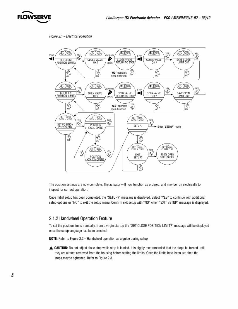
Figure 2.1 – Electrical operation
“NO ” operatesclose direction
“YES” operatesopen direction
Enter “SETUP ” mode
OPEN VALVERETURN TO STOP
OPEN VALVEOK ?
SAVE OPENLIMIT OK?
SETUP?
CLOSE VALVERETURN TO STOP
SAVE CLOSELIMIT OK?
CLOSE VALVEOK ?
CLOSE VALVEOK ?
EXITSETUP?
100% OPENSTATUS OK?
SET CLOSEPOSITION LIMIT?
YES
YES YES
YES
YES
YES YES YES
NO NONO NO NO
NONO
NO
NO
STOP
STOPSTOP
LOCAL
Switch to
LOCAL
Switch to
OPEN VALVEOK ?
SET OPENPOSITION LIMIT?
YES
NONO
SET POSITIONPRECISION?
POSITIONXXX% OPEN?
YES
NONO
POSITIONXXX.X% OPEN?
NO
YES
YES
The position settings are now complete. The actuator will now function as ordered, and may be run electrically to inspect for correct operation.
Once initial setup has been completed, the “SETUP?” message is displayed. Select “YES” to continue with additional setup options or “NO” to exit the setup menu. Confirm exit setup with “NO” when “EXIT SETUP” message is displayed.
2.1.2 Handwheel Operation FeatureTo set the position limits manually, from a virgin startup the “SET CLOSE POSITION LIMIT?” message will be displayed once the setup language has been selected.
NOTE: Refer to Figure 2.2 – Handwheel operation as a guide during setup
a CAUTION: Do not adjust close stop while stop is loaded. It is highly recommended that the stops be turned until they are almost removed from the housing before setting the limits. Once the limits have been set, then the stops maybe tightened. Refer to Figure 2.3.
9
Limitorque QX Electronic Actuator FCD LMENIM3313-02 – 03/12
flowserve.com
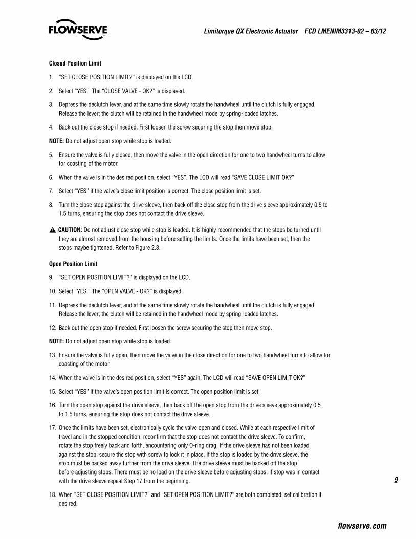
Closed Position Limit
1. “SET CLOSE POSITION LIMIT?” is displayed on the LCD.
2. Select “YES.” The “CLOSE VALVE - OK?” is displayed.
3. Depress the declutch lever, and at the same time slowly rotate the handwheel until the clutch is fully engaged. Release the lever; the clutch will be retained in the handwheel mode by spring-loaded latches.
4. Back out the close stop if needed. First loosen the screw securing the stop then move stop.
NOTE: Do not adjust open stop while stop is loaded.
5. Ensure the valve is fully closed, then move the valve in the open direction for one to two handwheel turns to allow for coasting of the motor.
6. When the valve is in the desired position, select “YES”. The LCD will read “SAVE CLOSE LIMIT OK?”
7. Select “YES” if the valve’s close limit position is correct. The close position limit is set.
8. Turn the close stop against the drive sleeve, then back off the close stop from the drive sleeve approximately 0.5 to 1.5 turns, ensuring the stop does not contact the drive sleeve.
a CAUTION: Do not adjust close stop while stop is loaded. It is highly recommended that the stops be turned until they are almost removed from the housing before setting the limits. Once the limits have been set, then the stops maybe tightened. Refer to Figure 2.3.
Open Position Limit
9. “SET OPEN POSITION LIMIT?” is displayed on the LCD.
10. Select “YES.” The “OPEN VALVE - OK?” is displayed.
11. Depress the declutch lever, and at the same time slowly rotate the handwheel until the clutch is fully engaged. Release the lever; the clutch will be retained in the handwheel mode by spring-loaded latches.
12. Back out the open stop if needed. First loosen the screw securing the stop then move stop.
NOTE: Do not adjust open stop while stop is loaded.
13. Ensure the valve is fully open, then move the valve in the close direction for one to two handwheel turns to allow for coasting of the motor.
14. When the valve is in the desired position, select “YES” again. The LCD will read “SAVE OPEN LIMIT OK?”
15. Select “YES” if the valve’s open position limit is correct. The open position limit is set.
16. Turn the open stop against the drive sleeve, then back off the open stop from the drive sleeve approximately 0.5 to 1.5 turns, ensuring the stop does not contact the drive sleeve.
17. Once the limits have been set, electronically cycle the valve open and closed. While at each respective limit of travel and in the stopped condition, reconfirm that the stop does not contact the drive sleeve. To confirm, rotate the stop freely back and forth, encountering only O-ring drag. If the drive sleeve has not been loaded against the stop, secure the stop with screw to lock it in place. If the stop is loaded by the drive sleeve, the stop must be backed away further from the drive sleeve. The drive sleeve must be backed off the stop before adjusting stops. There must be no load on the drive sleeve before adjusting stops. If stop was in contact with the drive sleeve repeat Step 17 from the beginning.
18. When “SET CLOSE POSITION LIMIT?” and “SET OPEN POSITION LIMIT?” are both completed, set calibration if desired.
Limitorque QX Electronic Actuator FCD LMENIM3313-02 – 03/12
10
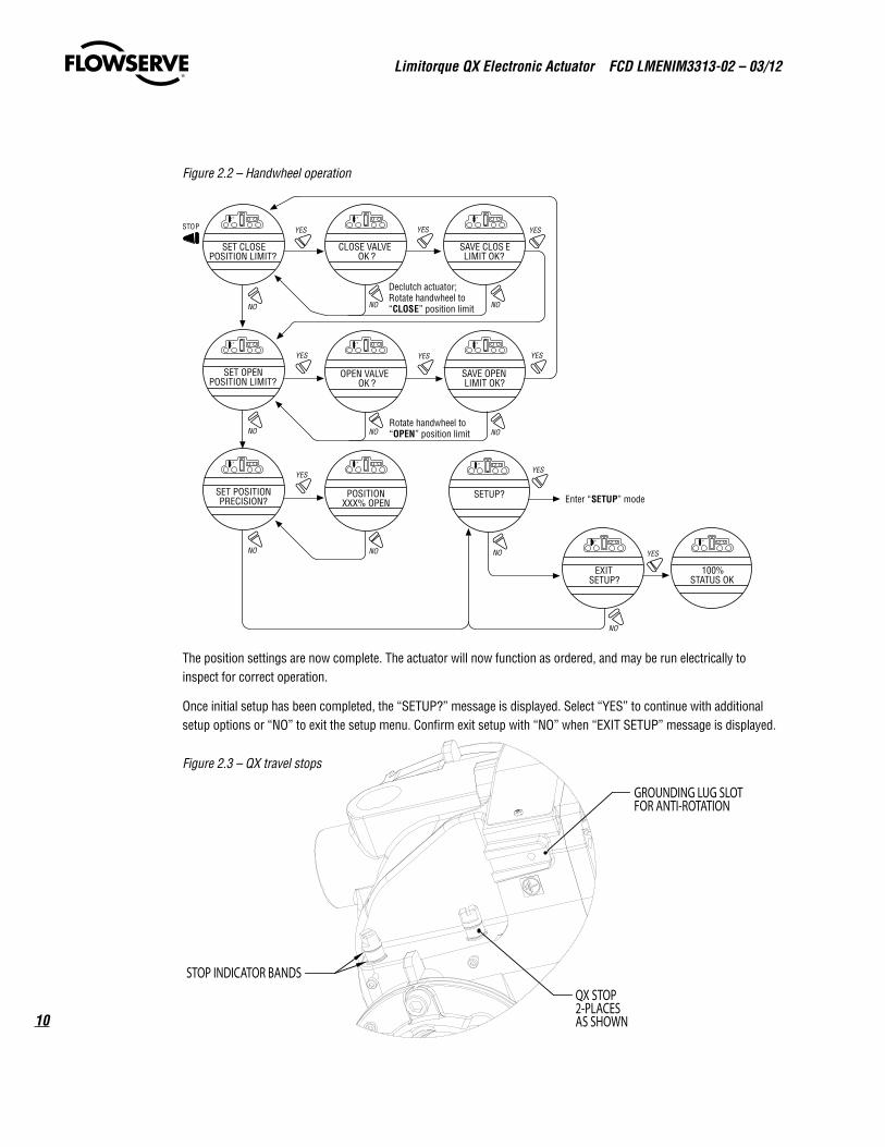
Figure 2.2 – Handwheel operation
Declutch actuator; Rotate handwheel to “ CLOS E ” position limit
Rotate handwheel to “ OPEN ” position limit
Enter “SETUP” mode
OPEN VALVE OK ?
SAVE OPEN LIMIT OK?
SETUP?
SAVE CLOS E LIMIT OK?
CLOSE VALVE OK ?
SET CLOS E POSITION LIMIT?
SET OPEN POSITION LIMIT?
EXITSETUP?
100%STATUS OK
YE S STO P YE S YE S
YE S YE S YE S
YES
YES
NO NO NO
NO NO NO
NO
NO
SET POSITIONPRECISION?
POSITIONXXX% OPEN
YES
NO NO
The position settings are now complete. The actuator will now function as ordered, and may be run electrically to inspect for correct operation.
Once initial setup has been completed, the “SETUP?” message is displayed. Select “YES” to continue with additional setup options or “NO” to exit the setup menu. Confirm exit setup with “NO” when “EXIT SETUP” message is displayed.
Figure 2.3 – QX travel stops
STOP INDICATOR BANDS
GROUNDING LUG SLOT FOR ANTI-ROTATION
QX STOP 2-PLACES AS SHOWN
11
Limitorque QX Electronic Actuator FCD LMENIM3313-02 – 03/12
flowserve.com
2.1.3 Entering the Setup ModeTo access the Setup Mode after initial setup has been exited, use these steps:
1. Place the red selector knob in the “STOP” position.
2. Within 10 seconds, place the black control knob in the “YES” position, then the “NO” position, then again in the “YES” position (in quick succession—approximately one to two seconds).
3. The message “SETUP?” will appear in the LCD display for 10 seconds. Select “YES”. If no setup action is taken within 10 seconds, the unit will reset.
4. Use the black control knob to answer “YES” or “NO” to the questions appearing in the display.
2.2 DDC OptionThe following instructions assume that all DDC option parameters are set with the exception of the address.
1. After setting position limits, remain in the “SETUP” mode. If not in the “SETUP” mode, enter the “SETUP” mode as detailed in Section 2.1.3, Entering the Setup Mode.
2. When LCD reads “CHANGE SETTINGS?”, select “YES.”
3. The LCD will display the “CHANGE SETTINGS” mode menu items. Select “NO” until screen displays “CHANGE DDC?” Select “YES.” LCD will display DDC menu items.
4. Select “YES” for each menu item until “DDC ADDRESS OK?” appears. Select “NO.”
5. Enter an address from 1 to 250 by toggling “NO” until the correct address is displayed. User may select to hold the knob in the “NO” direction and the number will automatically increment by one until the preferred address is reached.
NOTE: The DDC address does not have to be set to exit the setup.
a CAUTION: The network address must be entered in accordance with the user address assignment sheet. This assignment sheet should correspond to the contract specifications. The same address must not be used anywhere else in the same network. The DDC address does not have to be set to exit the setup.
2.3 Check the Settings1. Operate the valve to the fully “CLOSE” position. Verify that the “CLOSE” (default GREEN) LED illuminates just as
the travel limit is reached, and the valve position is displayed as “0% OPEN.”
2. Operate the valve to the fully “OPEN” position. Verify that the “OPEN” (default RED) LED illuminates just as the travel limit is reached, and the valve position is displayed as “100% OPEN.”
flowserve.com
To find your local Flowserve Limitorque representative:
Visit www.flowserve.com/limitorque or call 1-434-528-4400
Flowserve Corporation has established industry leadership in the design and manufacture of its products. When properly selected, this Flowserve product is designed to perform its intended function safely during its useful life. However, the purchaser or user of Flowserve products should be aware that Flowserve products might be used in numerous applications under a wide variety of industrial service conditions. Although Flowserve can (and often does) provide general guidelines, it cannot provide specific data and warnings for all possible applications. The purchaser/user must therefore assume the ultimate responsibility for the proper sizing and selection, installation, operation, and maintenance of Flowserve products. The purchaser/user should read and understand the Installation Operation Maintenance (IOM) instructions included with the product, and train its employees and contractors in the safe use of Flowserve products in connection with the specific application.
While the information and specifications contained in this literature are believed to be accurate, they are supplied for informative purposes only and should not be considered certified or as a guarantee of satisfactory results by reliance thereon. Nothing contained herein is to be construed as a warranty or guarantee, express or implied, regarding any matter with respect to this product. Because Flowserve is continually improving and upgrading its product design, the specifications, dimensions and information contained herein are subject to change without notice. Should any question arise concerning these provisions, the purchaser/user should contact Flowserve Corporation at any one of its worldwide operations or offices.
© 2012 Flowserve Corporation, Irving, Texas, USA. Flowserve is a registered trademark of Flowserve Corporation.
FCD LMENIM3313-02 03/12 Printed in USA.
Flowserve CorporationFlow Control
United StatesFlowserve Limitorque5114 Woodall Road P.O. Box 11318Lynchburg, VA 24506-1318Phone: 434-528-4400Facsimile: 434-845-9736
EnglandFlowserve LimitorqueEuro HouseAbex RoadNewburyBerkshire, RG14 5EYUnited KingdomPhone: 44-1-635-46999Facsimile: 44-1-635-36034
JapanLimitorque – Nippon Gear Co., Ltd.NOF Bldg. 9th Floor1-11-11, Kita-Saiwai, Nishi-KuYokohama (220-0004)JapanPhone: 81-45-326-2065Facsimile: 81-45-320-5962
SingaporeFlowserve Limitorque12, Tuas Avenue 20Singapore 638824Phone: 65-6868-4628Facsimile: 65-6862-4940
ChinaLimitorque Beijing, Pte., Ltd.RM A1/A222/F, East Area, Hanwei PlazaNo. 7 Guanghua Road, Chaoyang DistrictBeijing 100004, Peoples Republic of ChinaPhone: 86-10-5921-0606Facsimile: 86-10-6561-2702
IndiaFlowserve Limitorque, Ltd. Plot No 4 Export Promotional Industrial ParkWhitefield, Bangalore 560066 IndiaPhone: 91-80-40146200Facsimile: 91-80-28410286