lithium-ion battery storage and use hazards · 1 1100034.000 c0t0 0213 rtl1 lithium-ion battery...
TRANSCRIPT

1
1100034.000 C0T0 0213 RTL1
Lithium-Ion Battery Storage and Use Hazards
R. Thomas Long, P.E.
Mike Kahn, Ph.D.
Celina Mikolajczak, P.E.
February 28, 2013
SUPDET 2013 Orlando, FL

2
1100034.000 C0T0 0213 RTL1
Acknowledgements
The authors would like to thank:
The FPRF and the project sponsors for giving Exponent the opportunity to complete this work
The project Technical Panel for their many comments and suggestions
The Property Insurance Research Group (PIRG)

3
1100034.000 C0T0 0213 RTL1
Today’s Topics
Project History
Brief Technology Review
Brief Failure Incidents and Modes
Brief Battery Life Cycle / Applications Hazard Assessment
Survey Results
General Research Approach
Battery Acquisition
4
1100034.000 C0T0 0213 RTL1
Introduction
Phase 1: Lithium Ion Hazard and Use Assessment http://www.nfpa.org/assets/files/PDF/Research/RFLithiumIonBatteriesHazard.pdf
Phase 2:
A: Survey
B1: Test Planning and battery/cell acquisition/characterization
B2: Full scale testing (FM global)

5
1100034.000 C0T0 0213 RTL1
What Does Li-Ion Mean?
Li-ion refers to a family of battery chemistries
Negative (anode) and positive (cathode) electrode materials serve as hosts for lithium ions:
Ions intercalate into the electrode materials
No free lithium metal in a Li-ion cell
Rechargeable
No “standard” Li-ion cell
Electrolyte = flammable

6
1100034.000 C0T0 0213 RTL1
What is a Li-ion Cell?

7
1100034.000 C0T0 0213 RTL1
What is a Li-ion Battery?
A Li-ion battery pack contains
An enclosure
One or more cells
Protection electronics

8
1100034.000 C0T0 0213 RTL1
Cell Thermal Runaway
1. Cell internal temperature increases
2. Cell internal pressure increases
3. Cell undergoes venting
4. Cell vent gases may ignite
5. Cell contents may be ejected
6. Cell thermal runaway may propagate to adjacent cells
Cell
windings
Open center
of cell
Blockage in
center of cell
Pressure
buildup at
base

9
1100034.000 C0T0 0213 RTL1
Thermal Runaway- How do you get there
Thermal Abuse: The most direct way to exceed the thermal stability limits of a Li-ion cell is to subject it to external heating
Mechanical Abuse: Mechanical abuse of cells can cause shorting between cell electrodes, leading to localized cell heating that propagates to the entire cell and initiates thermal runaway;
Electrical Abuse: Overcharge, External Short Circuit, Over-discharge
Internal Cell Faults: For commercial Li-ion battery packs with mature
protection electronics packages, the majority of thermal runaway
failures in the field are caused by internal cell faults

10
1100034.000 C0T0 0213 RTL1
Battery Life Cycle Hazards
Key Finding: Warehouse setting was frequent throughout
lifecycle of batteries
Warehouse setting
Failure modes:
Mechanical abuse – cells being crushed, punctured, dropped
Electrical abuse – short circuiting improperly packaged cells/ packs
Thermal abuse – external fire
Internal fault – unlikely unless cells being charged
Mitigation:
Cells/packs usually stored at reduced states of charge (50% SOC or less)
Cells and packs can be contained in packaging to prevent mechanical and external short circuit damage
Fire suppression strategies

11
1100034.000 C0T0 0213 RTL1
Knowledge Gaps
Gap 1: Leaked Electrolyte & Vent Gas Composition
Gap 2: Sprinkler Protection criteria for Li-ion Cells
Gap 3: Effectiveness of Various Suppressants
Gap 4: Post – Fire Cleanup Issues

12
1100034.000 C0T0 0213 RTL1
Gap 2: Sprinkler Protection
2.1: At present there is no fire protection suppression strategy for
Li-ion cells
2.1a: Bulk packaged Li-ion cells
2.1b: Large format Li-ion cells
2.1c: Li-ion cells contained in or packed with equipment

13
1100034.000 C0T0 0213 RTL1
Gap 2: Overview
Current infrastructure in most occupancies includes the ability to provide water based fire protection systems
Currently not known if water is the most appropriate extinguishing medium for Li-ion batteries
NFPA 13 does not provide a specific recommendation for the protection of or fire protection strategies for Li-ion cells or complete batteries

14
1100034.000 C0T0 0213 RTL1
Gap 2: Sprinkler Protection for Li-Ion
NFPA 13 ‘battery” Commodity Classifications
NFPA 13 provides a list of commodity classes for various
commodities in Table A.5.6.3.
Dry cells (non-lithium or similar exotic metals) packaged in cartons: Class I (for example alkaline cells);
Dry cells (non-lithium or similar exotic metals) blister packed in cartons: Class II (for example alkaline cells);
Automobile batteries – filled: Class I (typically lead acid batteries with water-based electrolyte);
Truck or larger batteries, empty or filled Group A Plastics (typically lead acid batteries with water-based electrolyte);
Li-ion chemistries are not included
Full Scale testing appropriate

15
1100034.000 C0T0 0213 RTL1
Gap 2: Sprinkler Protection for Li-Ion
For full scale tests needed to define
Commodities
Cell chemistry
Cell size / form factor
Cell SOC
Packaging configuration
Storage geometries and arrangments
Full scale tests of every cell type / configuration is not practical
Select a “most typical case”
Purchasing commodities for testing is expensive

16
1100034.000 C0T0 0213 RTL1
Survey
Conducted in 2012
Responders were typically engaged in:
Manufacturing
Research
Recycling
Almost all responders stored batteries, cells, or devices with batteries/cells.

17
1100034.000 C0T0 0213 RTL1
Survey Responses Summary
Battery Types at the Surveyed Facilities: Cylindrical cells
were the most common form factor. Small format was the most
common size.
Tasks Carried Out at Facilities Surveyed: Most of the
responding facilities were engaged in the storage of cells, battery
packs or devices.
Packaging of Received Batteries: Cells typically arrive in
cardboard boxes. These boxes may be on wooden pallets and/or
encapsulated.
Rack storage type: Movable racks were more common than
fixed racks, and shelves were more likely to be perforated than solid.

18
1100034.000 C0T0 0213 RTL1
Battery Aquissition
Parameter Power tool 18650 18650 Li-Polymer
Nominal voltage 3.7 V 3.7 V 3.7 V
Nominal capacity 1300 mAh 2600 mAh 2700 mAh
Mass of Cell 42.9 g 47.2 g 50.0 g
Approximate mass of
electrolyte solvent
3.3 g 2.6 g 4.0 g
Cell chemistry Lithium Nickel
Manganese Cobalt
Oxide (NMC)
Lithium Cobalt Oxide
(LCO)
Lithium Cobalt Oxide
(LCO)
Approx. state of charge
(SOC) as received
50% 40% 60%

19
1100034.000 C0T0 0213 RTL1
Ryobi P104 Power Tool Packs – Overview
18 V, 48 Wh Lithium-Ion power tool packs selected over lower voltage, lower capacity packs in
an effort to maximize the ratio of lithium-ion battery cells to packaging materials
The battery packs measure approximately (5 ½” long) x (3 ¼” wide) x (4 ¼” tall)
Blister packs plus casing presented an appreciable amount of plastics
Onboard “fuel gauge” indicator lights orange, indicating mid state of charge

20
1100034.000 C0T0 0213 RTL1
Ryobi P104 Power Tool Packs – Construction
Battery pack materials include a protection PCB, spot-welded nickel interconnects, hard plastic
structural elements, flexible rubber elements (rubber feet and internal flexible rubber padding), and
soft foam padding for vibration resistance
Hard injection-molded plastic shell
Rubber feet
Bottom View
Hard plastic frame
Soft foam padding
Protection printed circuit board (PCB) / Battery Management Unit (BMU)
Flexible rubber padding
21
1100034.000 C0T0 0213 RTL1
Ryobi P104 Power Tool Packs –
Characterization
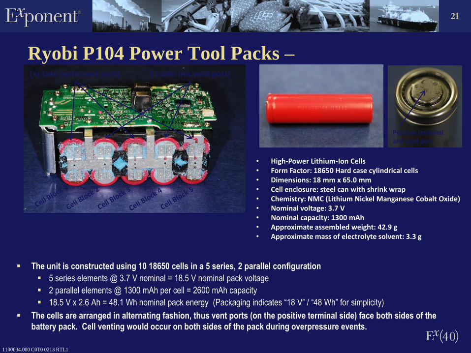
The unit is constructed using 10 18650 cells in a 5 series, 2 parallel configuration
5 series elements @ 3.7 V nominal = 18.5 V nominal pack voltage
2 parallel elements @ 1300 mAh per cell = 2600 mAh capacity
18.5 V x 2.6 Ah = 48.1 Wh nominal pack energy (Packaging indicates “18 V” / “48 Wh” for simplicity)
The cells are arranged in alternating fashion, thus vent ports (on the positive terminal side) face both sides of the
battery pack. Cell venting would occur on both sides of the pack during overpressure events.
• High-Power Lithium-Ion Cells • Form Factor: 18650 Hard case cylindrical cells • Dimensions: 18 mm x 65.0 mm • Cell enclosure: steel can with shrink wrap • Chemistry: NMC (Lithium Nickel Manganese Cobalt Oxide) • Nominal voltage: 3.7 V • Nominal capacity: 1300 mAh • Approximate assembled weight: 42.9 g • Approximate mass of electrolyte solvent: 3.3 g
(+) side (with vent port) (-) side (no vent port)
Positive terminal and vent port

22
1100034.000 C0T0 0213 RTL1
Power Tool Packs – SOC
Two battery packs were measured for voltage and capacity
Both battery packs were 18.60 V (corresponding to 3.72 V per series element)
Battery packs are close to the nominal pack voltage of 18.5 V (or nominal cell voltage of 3.7 V)
A battery pack at the nominal voltage usually indicates it is near the halfway point of charge
A fully charged pack would be 21 V (4.2 V x 5 series elements)
State of Charge (SOC) was measured on one cell from each of two battery packs (S/N listed above) using
a standard C/5 rate (0.26 A) constant current discharge until 2.5V was reached
Both cells were determined to be close to 50% SOC
V of NFPA-sanyo-18650.015
V of NFPA-sanyo-18650.008
Capacity/mAh
6005004003002001000
Voltage/V
4.2
4.1
4
3.9
3.8
3.7
3.6
3.5
3.4
3.3
3.2
3.1
3
2.9
2.8
2.7
2.6
2.5
Discharge Capacity Pack S/ CS12233D430739 – 667 mAh (50% SOC) CS12271N430014 – 652 mAh (49% SOC)
Initial voltage 3.72 V

23
1100034.000 C0T0 0213 RTL1
Ryobi Packs – Sanyo 18650 Cell Disassembly
Electrodes are in a jelly roll configuration,
typical of 18650 cells
One cell was disassembled and the positive
electrode was subjected to energy
dispersive X-ray spectroscopy (EDS) to
assess cell chemistry
Cell chemistry is consistent with NMC
(lithium nickel manganese cobalt oxide)
chemistry, i.e. Li(NixMnyCoz)O2 where x, y,
and z can vary depending on manufacturer’s
formula
Negative electrode (on Cu foil)
Positive electrode (on Al foil)
Separator
Separator
Mn
Co
Ni
Positive cell tab
EDS Spectrum
O
Steel can

24
1100034.000 C0T0 0213 RTL1
18650 Cells – Characterization
• 18650 Lithium-Ion Cells • Form Factor: Hard case cylindrical cell
(18 mm diameter x 65.0 mm) • Cell enclosure: steel can with shrink wrap • Chemistry: LCO (Lithium cobalt oxide) • Nominal voltage: 3.7 V • Nominal capacity: 2600 mAh • Approximate assembled weight: 47.2 g • Approximate mass of electrolyte solvent: 2.6 g
Jelly roll in cell can

25
1100034.000 C0T0 0213 RTL1
2.5
2.7
2.9
3.1
3.3
3.5
3.7
3.9
4.1
4.3
0 0.2 0.4 0.6 0.8 1 1.2
Vo
ltag
e (
V)
Capacity (Ah)
18650 Channel 8
18650 Channel 15
18650 Cells – State of charge (SOC)
Two cells were measured for voltage and capacity
Both cells were 3.74 V, close to the nominal cell voltage of 3.7 V
A battery pack at the nominal voltage usually indicates it is near the halfway point of charge
A fully charged cell would be 4.2 V
State of Charge (SOC) was measured on two cells using a standard C/5 rate (0.52 A) constant current
discharge until 3.0 V was reached
Discharge Capacity Cell capacities: 1.05 Ah (40% SOC) 1.05 Ah (40% SOC)
Initial voltage 3.74 V

26
1100034.000 C0T0 0213 RTL1
18650 Cells – Cell Disassembly
Electrodes are in a jelly roll
configuration, typical of 18650 cells
One 18650C was disassembled and
the positive electrode was subjected
to energy dispersive X-ray
spectroscopy (EDS) to assess cell
chemistry
Cell chemistry is consistent with LCO
(lithium cobalt oxide) chemistry, i.e.
LiCoO2
Steel can
Negative electrode (on Cu foil)
Positive electrode (on Al foil)
Separator
Separator
O
Co EDS Spectrum

27
1100034.000 C0T0 0213 RTL1
Li-Polymer Cells – Characterization
• Lithium-Polymer Cells • Form Factor: Li-polymer (soft pack) cell • Dimensions: 6 mm thick x 41 mm x 99 mm • Cell enclosure: aluminum foil with polymer coating • Electrode configuration: jelly roll (as opposed to
stacked) • Chemistry: LCO (Lithium cobalt oxide) • Nominal voltage: 3.7 V • Nominal capacity: 2700 mAh • Approximate assembled weight: 50.0 g • Approximate mass of electrolyte solvent: 4.0 g
Coated aluminum pouch
Cell windings (“Jelly roll”)
Cell enclosure is aluminum foil coated with polymer, and is designed to be
electrically neutral and insulated
+ tab
– tab

28
1100034.000 C0T0 0213 RTL1
2.5
2.7
2.9
3.1
3.3
3.5
3.7
3.9
4.1
4.3
0 0.5 1 1.5 2
Vo
ltag
e (
V)
Capacity (Ah)
Pouch 9I19
Pouch 9H27_1
Li-Polymer Cells – SOC
Two cells were measured for voltage and capacity
Both cells were 3.84 V
Battery packs are close to the nominal cell voltage of 3.7 V
A battery pack at the nominal voltage usually indicates it is near the halfway point of charge
A fully charged cell would be 4.2 V
SOC was measured on two cells using a standard C/5 rate (0.54 A) constant current discharge until 3.0 V
was reached
Discharge Capacity Cell markings: 9H27 – 1.62 Ah (60% SOC) 9I19 – 1.66 Ah (61% SOC)
Initial voltage 3.84 V

29
1100034.000 C0T0 0213 RTL1
Li-Polymer Cells – Cell Disassembly
Electrodes are in a jelly roll
configuration, as opposed to stacked
electrode design
One Li polymer cell was disassembled
and the positive electrode was
subjected to energy dispersive X-ray
spectroscopy (EDS) to assess cell
chemistry
Cell chemistry is consistent with LCO
(lithium cobalt oxide) chemistry, i.e.
LiCoO2
Al Pouch
Negative electrode (on Cu foil)
Positive electrode (on Al foil)
Separator
Separator
O
Co EDS Spectrum

30
1100034.000 C0T0 0213 RTL1
Flammability Characterization
Full scale tests
Limited quantities of batteries/cells
Rack storage arrangement
Free burn/external ignition source
Hard and soft case batteries with similar energy
densities
Battery packs with appreciable plastics
Due to costs, tests required an unique approach to full
scale tests – FM Global – reduced commodity testing