lmenim2100-00 wg series - flowserve · 5 3501024 1014 ˜owserve.com 2.1 initial inspection and...
TRANSCRIPT

Experience In Motion
USER INSTRUCTIONS
InstallationOperation
Maintenance
Limitorque HBC SeriesFCD LMENIM3501-02-A4 (10/14)
Limitorque HBC Series FCD LMENIM3501-02-A4 – 10/14
2
Contents1 Introduction 3
1.1 Purpose 31.2 User Safety 3
2 Inspection, Installation, and Mounting Procedures 42.1 Initial Inspection and Storage Instructions 52.2 Inspection and Recording 52.3 Storage Procedure 52.4 General Mounting Instructions 62.5 Setting Position Limit Stops for HBC-0 through -3 62.6 Setting Position Limit Stops for HBC-4 through -7 72.7 HBC Angular Displacement Tolerances 8
3 Lubrication 94 Dissassembly and Reassembly Instructions 11
4.1 Safety Precautions 114.2 Safety Practices 124.3 HBC-0 through -3 124.4 HBC-4 through -7 134.5 Spur Gear Attachments 15
5 Setting Instructions for AWWA Input Shaft Stop 186 How to Order Parts 23
FiguresFigure 2.1 – HBC-0 through -3 exploded view 4Figure 2.2 – HBC nameplate 5Figure 2.3 – Hex nut type stop (HBC-0 through -3) 7Figure 2.4 – Top of drive sleeve showing available rotation 8Figure 4.1 – HBC-0 through -3 assembly 12Figure 4.2 – HBC-4 through -7 assembly 14Figure 4.3 – Spur gear attachments 16–17Figure 5.1 – AWWA input shaft stop (back view) 20Figure 5.2 – AWWA input shaft stop (complete view) 21
TablesTable 2.1 – HBC angular displacement tolerance 8Table 3.1 – Lubricant weights 10Table 4.1 – HBC-0 through -3 parts list 13Table 4.2 – HBC-4 through -7 parts list 14Table 4.3 – HBC-1 through -7 spur gear attachments parts list 17Table 5.1 – AWWA input shaft stop parts list 22
3
Limitorque HBC Series FCD LMENIM3501-02-A4 – 10/14
flowserve.com
1.1 PurposeThis installation, operation and maintenance manual (IOM) explains how to install and maintain the Flowserve Limitorque HBC gearbox. Information on installation, disassembly, reassembly, lubrication, and spare parts is provided.
1.2 User SafetySafety notices in this manual detail precautions the user must take to reduce the risk of personal injury and damage to the equipment. The user must read and be familiar with these instructions before attempting installation, operation, or maintenance. Failure to observe these precautions could result in serious bodily injury, damage to the equipment, voiding of the warranty, or operational difficulty.
Safety notices are presented in this manual in three forms:
c WARNING: Refers to personal safety. Alerts the user to potential danger. Failure to follow warning notices could result in personal injury or death.
a CAUTION: Directs the user’s attention to general precautions that, if not followed, could result in personal injury and/or equipment damage.
NOTE: Highlights information critical to the user’s understanding of the HBC gearbox’s installation and operation.
1 Introduction
Limitorque HBC Series FCD LMENIM3501-02-A4 – 10/14
4
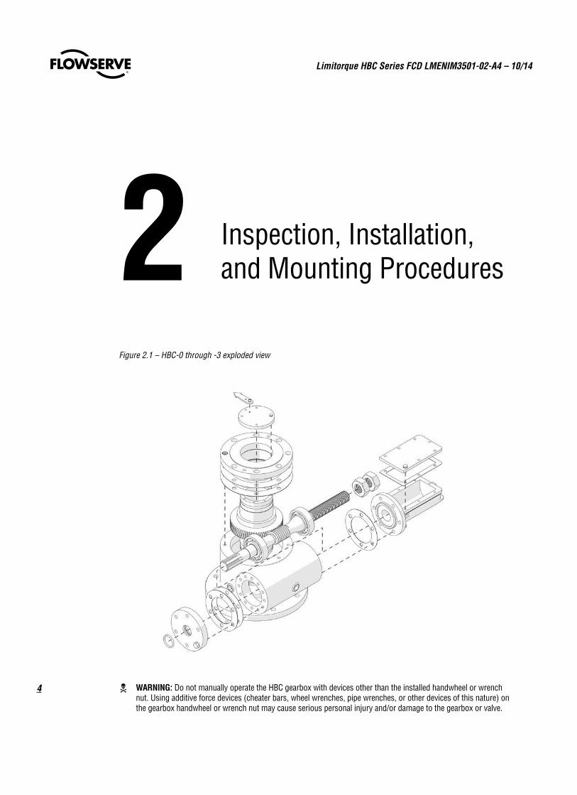
2 Inspection, Installation, and Mounting Procedures
c WARNING: Do not manually operate the HBC gearbox with devices other than the installed handwheel or wrench nut. Using additive force devices (cheater bars, wheel wrenches, pipe wrenches, or other devices of this nature) on the gearbox handwheel or wrench nut may cause serious personal injury and/or damage to the gearbox or valve.
Figure 2.1 – HBC-0 through -3 exploded view
5
Limitorque HBC Series FCD LMENIM3501-02-A4 – 10/14
flowserve.com
2.1 Initial Inspection and Storage Instructions
c WARNING: Read this installation, operation and maintenance manual completely before attempting to store the gearbox. If an electric actuator is attached to the HBC gearbox, be aware of the electrical hazards. Consult the actuator installation, operation and maintenance manual for guidance.
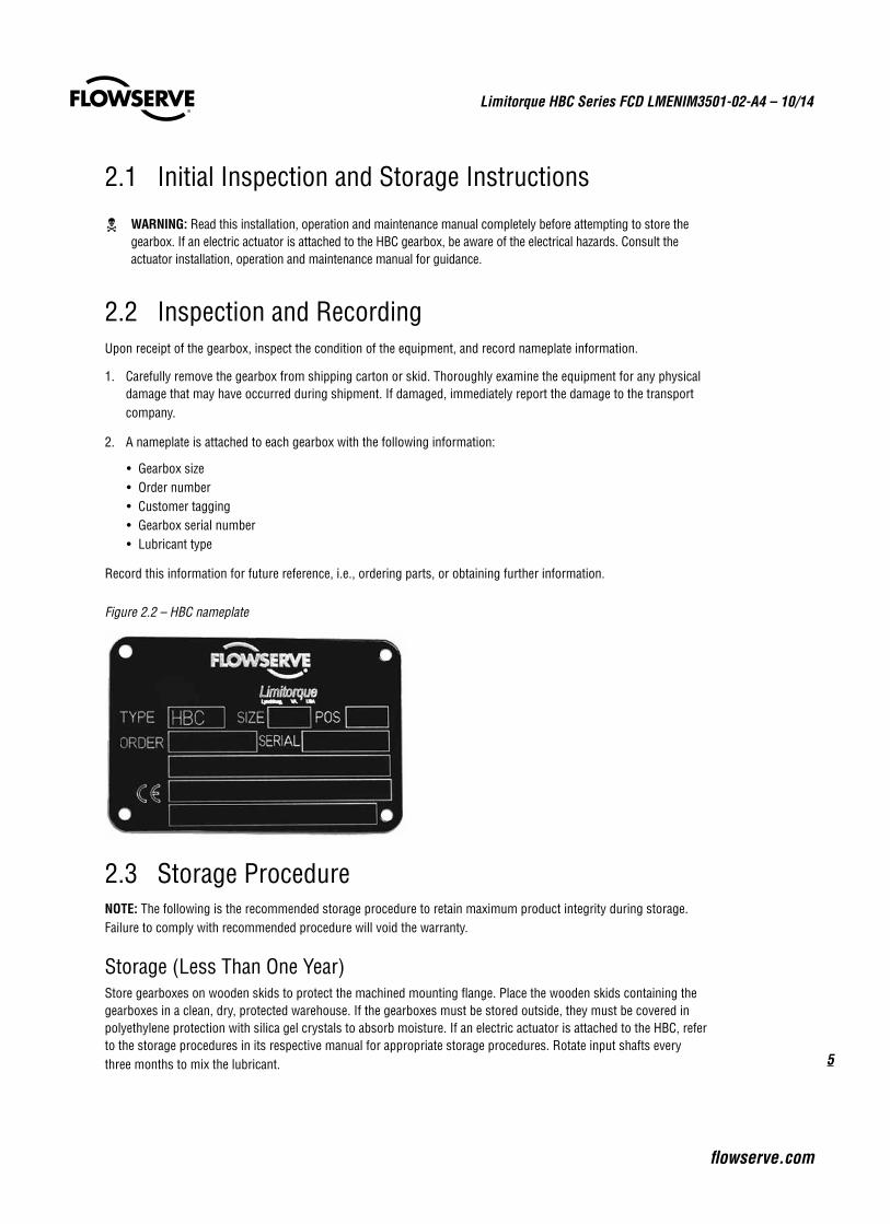
2.2 Inspection and RecordingUpon receipt of the gearbox, inspect the condition of the equipment, and record nameplate information.
1. Carefully remove the gearbox from shipping carton or skid. Thoroughly examine the equipment for any physical damage that may have occurred during shipment. If damaged, immediately report the damage to the transport company.
2. A nameplate is attached to each gearbox with the following information:
• Gearbox size• Order number• Customer tagging• Gearbox serial number• Lubricant type
Record this information for future reference, i.e., ordering parts, or obtaining further information.
Figure 2.2 – HBC nameplate
2.3 Storage ProcedureNOTE: The following is the recommended storage procedure to retain maximum product integrity during storage. Failure to comply with recommended procedure will void the warranty.
Storage (Less Than One Year)Store gearboxes on wooden skids to protect the machined mounting flange. Place the wooden skids containing the gearboxes in a clean, dry, protected warehouse. If the gearboxes must be stored outside, they must be covered in polyethylene protection with silica gel crystals to absorb moisture. If an electric actuator is attached to the HBC, refer to the storage procedures in its respective manual for appropriate storage procedures. Rotate input shafts every three months to mix the lubricant.
Limitorque HBC Series FCD LMENIM3501-02-A4 – 10/14
6
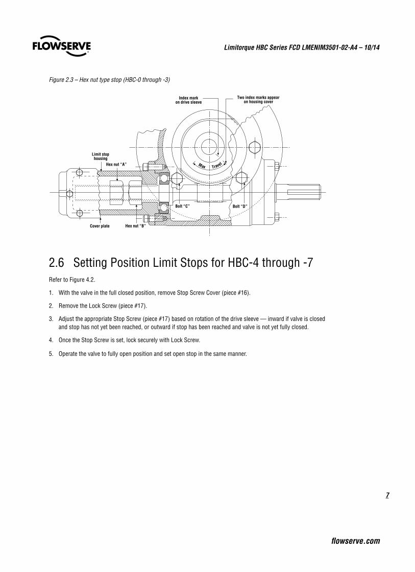
2.4 General Mounting Instructionsa CAUTION: To avoid disengaging the worm gear segment, ensure that the index mark on the drive sleeve (center-
line of gear segment) is oriented to the midpoint of the 90° valve travel. Full stroke rotation of this index mark should not move past the corresponding travel limit index marks on the housing cover. Should the housing cover index marks not be visible, the two housing cover bolts (“C” and “D”) can be used for this alignment. Refer to Figure 2.3.
1. Place the valve in full closed position.
2. Press the splined adapter on valve shaft and insert key (should be a press fit to avoid splined adapter movement in HBC drive sleeve), or utilize a set screw to eliminate movement of splined adapter on the valve shaft.
3. Remove the pointer cap from HBC gearbox.
4. Turn the HBC gearbox input shaft to full closed position. The stops are preset for 90° travel. Be certain of correct direction of rotation.
5. Mount the gearbox on the valve and bolt securely. Be sure of gearbox stop alignment before engaging splines. (See angular displacement tolerances in Table 2.1.)
6. For standard stop setting instructions, see Section 2.5, Setting Position Limit Stops for HBC-0 through -3.
7. For gearboxes with AWWA input shaft stop, see Section 5, Setting Instructions for AWWA Input Shaft Stop.
2.5 Setting Position Limit Stops for HBC-0 through -3Refer to Figure 2.3.
1. With the valve in full closed position, remove limit stop cover plate.
2. You will note two traveling hex nuts, “A” and “B.”
a. If hex nut “B” is near the position shown, run the hex nut hand-tight against the housing so that one of the flats of the hex nut is on top, facing the cover plate. (If hex nut “A” is near the opposite end of the limit stop housing, proceed with Step 4 first.)
b. If hex nut “A” or “B” hits the housing before the valve was tightly closed, back off the hex nut until the valve is tight and proceed as in Step 2a.
3. Replace the limit stop cover plate and turn the input shaft of the HBC gearbox to fully open the valve.
4. Remove the limit stop cover plate and check the position of hex nut “A.” This nut should be turned until it is flush up against the end of the limit stop housing and one of the flats of the nut is on top facing the limit stop housing cover plate.
5. Bolt the limit stop cover plate into position.
7
Limitorque HBC Series FCD LMENIM3501-02-A4 – 10/14
flowserve.com
Figure 2.3 – Hex nut type stop (HBC-0 through -3)
Index markon drive sleeve
Two index marks appearon housing cover
Hex nut “B”Cover plate
Bolt “C” Bolt “D”
Hex nut “A”
Limit stophousing
Max Travel
2.6 Setting Position Limit Stops for HBC-4 through -7Refer to Figure 4.2.
1. With the valve in the full closed position, remove Stop Screw Cover (piece #16).
2. Remove the Lock Screw (piece #17).
3. Adjust the appropriate Stop Screw (piece #17) based on rotation of the drive sleeve — inward if valve is closed and stop has not yet been reached, or outward if stop has been reached and valve is not yet fully closed.
4. Once the Stop Screw is set, lock securely with Lock Screw.
5. Operate the valve to fully open position and set open stop in the same manner.
Limitorque HBC Series FCD LMENIM3501-02-A4 – 10/14
8
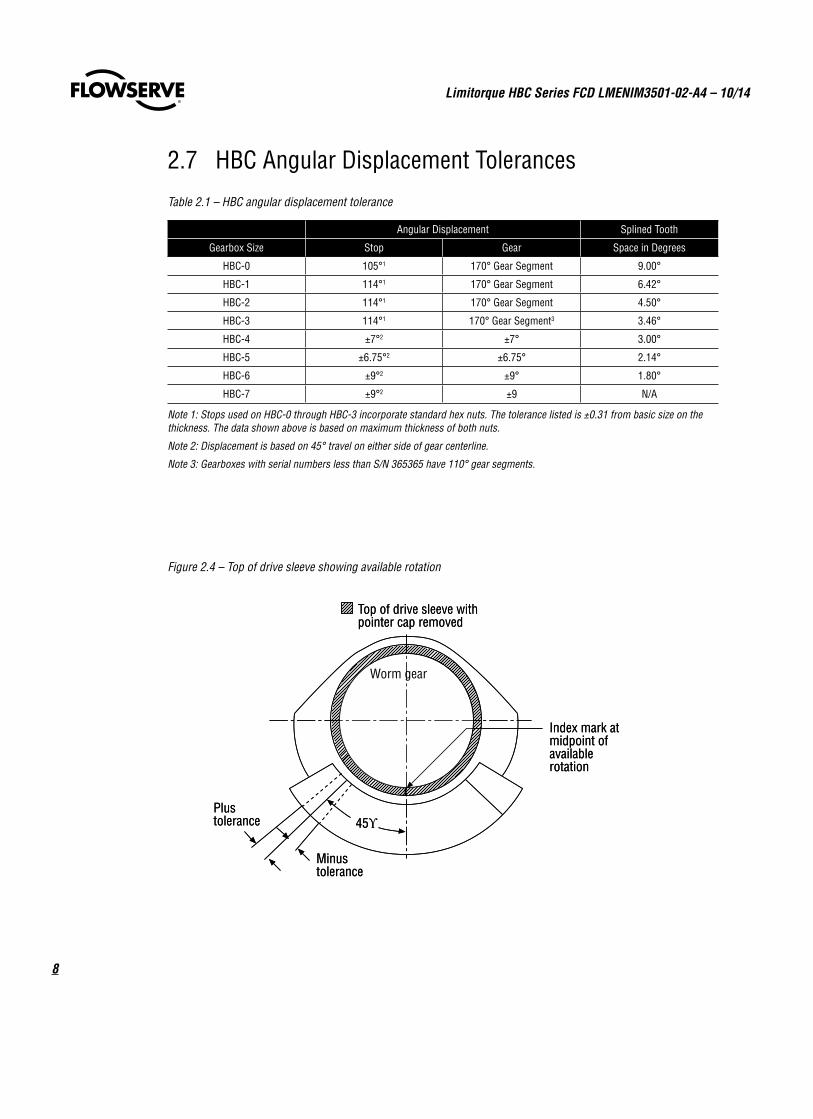
Top of drive sleeve withpointer cap removed
Worm gear
Index mark atmidpoint ofavailablerotation
Plustolerance 45ϒ
Minustolerance
Top of drive sleeve withpointer cap removed
Worm gear
Index mark atmidpoint ofavailablerotation
Plustolerance 45ϒ
Minustolerance
Figure 2.4 – Top of drive sleeve showing available rotation
2.7 HBC Angular Displacement Tolerances
Table 2.1 – HBC angular displacement tolerance
Angular Displacement Splined Tooth
Gearbox Size Stop Gear Space in Degrees
HBC-0 105°1 170° Gear Segment 9.00°
HBC-1 114°1 170° Gear Segment 6.42°
HBC-2 114°1 170° Gear Segment 4.50°
HBC-3 114°1 170° Gear Segment3 3.46°
HBC-4 ±7°2 ±7° 3.00°
HBC-5 ±6.75°2 ±6.75° 2.14°
HBC-6 ±9°2 ±9° 1.80°
HBC-7 ±9°2 ±9 N/A
Note 1: Stops used on HBC-0 through HBC-3 incorporate standard hex nuts. The tolerance listed is ±0.31 from basic size on the thickness. The data shown above is based on maximum thickness of both nuts.
Note 2: Displacement is based on 45° travel on either side of gear centerline.
Note 3: Gearboxes with serial numbers less than S/N 365365 have 110° gear segments.
9
Limitorque HBC Series FCD LMENIM3501-02-A4 – 10/14
flowserve.com
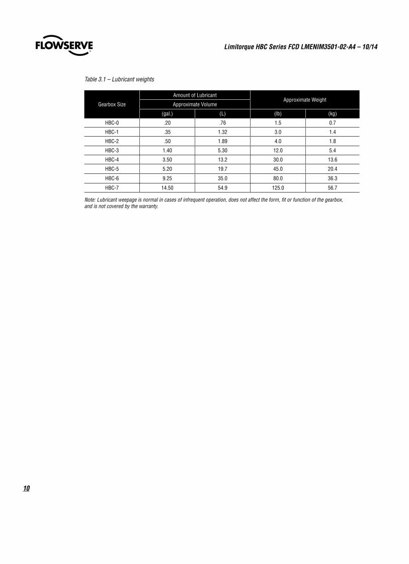
3 Lubrication
Flowserve Limitorque HBC gearboxes are factory lubricated with an NLGI grade 0 calcium sulphonate grease suitable for a temperature range of -20°F to +150°F (-29°C to +60°C). Other lubricants approved by Flowserve Limitorque may be used based on customer requirements. See the nameplate for lubricant type.
QuantityLimitorque gearboxes are built to operate on the partial immersion principle. The primary concern regarding the amount of lubricant is whether the “worm” is totally immersed in grease. This can be verified by the use of one or more of the many “fill” and “drain” plugs provided on the gearbox housing.
QualityWhen removing a “fill” or “drain” plug to inspect the lubricant level, remove a small amount and ensure that it is clean and free of any contaminant, including water. Should dirt, water, or other foreign matter be found, the lubricant must be replaced and will require some partial disassembly. Contact Flowserve Limitorque with the gearbox order number or serial number for replacement parts.
ConsistencyThe main gearbox lubricant should be slightly fluid, approximating a standard NLGI-0 grade consistency.
Alternate lubricants may be used in place of the standard lubricants supplied by Flowserve, provided they are a calcium sulphonate or similar lubricant.
a CAUTION: Do not add a different lubricant to a Flowserve Limitorque gearbox unless it is of the same soap base as the existing lubricant, or you have received the approval of the lubricant manufacturer.
Limitorque HBC Series FCD LMENIM3501-02-A4 – 10/14
10
Gearbox Size
Amount of LubricantApproximate Weight
Approximate Volume
(gal.) (L) (lb) (kg)
HBC-0 .20 .76 1.5 0.7
HBC-1 .35 1.32 3.0 1.4
HBC-2 .50 1.89 4.0 1.8
HBC-3 1.40 5.30 12.0 5.4
HBC-4 3.50 13.2 30.0 13.6
HBC-5 5.20 19.7 45.0 20.4
HBC-6 9.25 35.0 80.0 36.3
HBC-7 14.50 54.9 125.0 56.7
Note: Lubricant weepage is normal in cases of infrequent operation, does not affect the form, fit or function of the gearbox, and is not covered by the warranty.
Table 3.1 – Lubricant weights
11
Limitorque HBC Series FCD LMENIM3501-02-A4 – 10/14
flowserve.com
4 Dissassembly and Reassembly Instructions
4.1 Safety Precautionsc WARNING: Read this Installation, Operation and Maintenance Manual completely before attempting to install,
operate, or troubleshoot the Flowserve Limitorque gearbox.
c WARNING: Potential HIGH-PRESSURE vessel — be aware of high-pressure hazards associated with the attached valve or other actuated device when installing or performing maintenance on the gearbox. Do not remove the gearbox mounting bolts from the valve or actuated device unless the valve or device stem is secured or there is no pressure in the line.
c WARNING: For maintenance and/or disassembly of the gearbox while installed on the valve, ensure that the gearbox is not under thrust or torque load. If the valve must be left in service, the valve stem must be locked in such a way as to prevent any movement of the valve stem.
c WARNING: Do not manually operate the gearbox with devices other than the installed handwheel. Using force beyond the ratings of the gearbox and/or using additive force devices such as cheater bars, wheel wrenches, pipe wrenches, or other devices on the gearbox handwheel may cause serious personal injury and/or damage to the gearbox and valve.
c WARNING: Do not exceed any design limitations or make modifications to this equipment without first consulting Flowserve Limitorque.
c WARNING: Use of the product must be suspended any time it fails to operate properly.
a CAUTION: If a motor actuator is driving the gearbox, do not operate the valve under motor operation without first checking and setting the limit switch setting and checking for correct motor rotation.
a CAUTION: Do not use replacement parts that are not Flowserve Limitorque parts, as serious personal injury and/or damage to the gearbox and valve may result.
Limitorque HBC Series FCD LMENIM3501-02-A4 – 10/14
12
4.2 Safety PracticesThe following checkpoints should be performed to maintain safe operation of the HBC gearbox:
• Set up a periodic operating schedule on infrequently used valves.
• Ensure that the limit and/or torque switches on any electric actuator fitted to the HBC worm gearbox are correctly and appropriately adjusted.
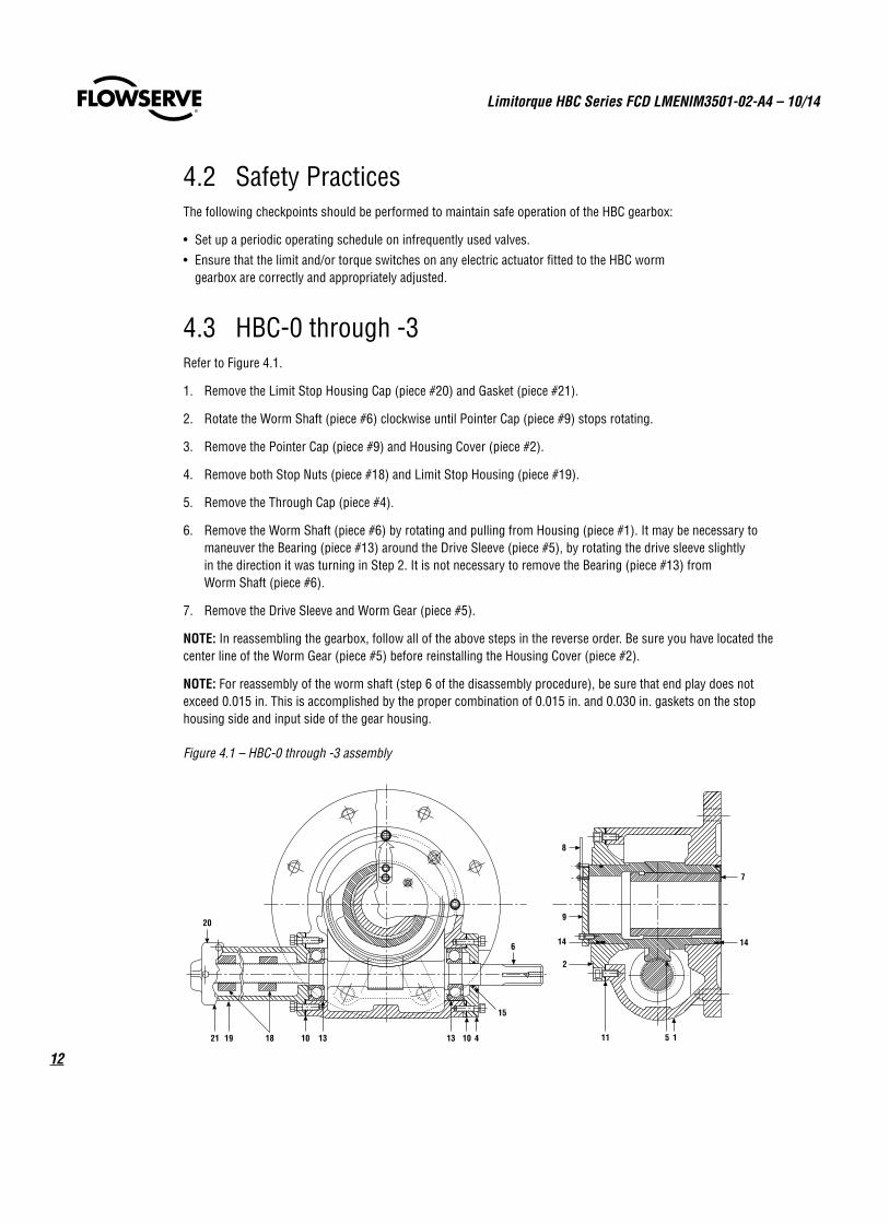
4.3 HBC-0 through -3Refer to Figure 4.1.
1. Remove the Limit Stop Housing Cap (piece #20) and Gasket (piece #21).
2. Rotate the Worm Shaft (piece #6) clockwise until Pointer Cap (piece #9) stops rotating.
3. Remove the Pointer Cap (piece #9) and Housing Cover (piece #2).
4. Remove both Stop Nuts (piece #18) and Limit Stop Housing (piece #19).
5. Remove the Through Cap (piece #4).
6. Remove the Worm Shaft (piece #6) by rotating and pulling from Housing (piece #1). It may be necessary to maneuver the Bearing (piece #13) around the Drive Sleeve (piece #5), by rotating the drive sleeve slightly in the direction it was turning in Step 2. It is not necessary to remove the Bearing (piece #13) from Worm Shaft (piece #6).
7. Remove the Drive Sleeve and Worm Gear (piece #5).
NOTE: In reassembling the gearbox, follow all of the above steps in the reverse order. Be sure you have located the center line of the Worm Gear (piece #5) before reinstalling the Housing Cover (piece #2).
NOTE: For reassembly of the worm shaft (step 6 of the disassembly procedure), be sure that end play does not exceed 0.015 in. This is accomplished by the proper combination of 0.015 in. and 0.030 in. gaskets on the stop housing side and input side of the gear housing.
Figure 4.1 – HBC-0 through -3 assembly
20
21 19 18 10 13 13 10 4
15
6
9
2
14
11 5
14
1
7
8
13
Limitorque HBC Series FCD LMENIM3501-02-A4 – 10/14
flowserve.com
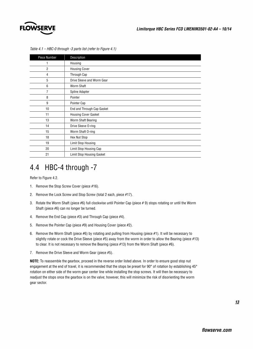
Table 4.1 – HBC-0 through -3 parts list (refer to Figure 4.1)
Piece Number Description
1 Housing
2 Housing Cover
4 Through Cap
5 Drive Sleeve and Worm Gear
6 Worm Shaft
7 Spline Adapter
8 Pointer
9 Pointer Cap
10 End and Through Cap Gasket
11 Housing Cover Gasket
13 Worm Shaft Bearing
14 Drive Sleeve O-ring
15 Worm Shaft O-ring
18 Hex Nut Stop
19 Limit Stop Housing
20 Limit Stop Housing Cap
21 Limit Stop Housing Gasket
4.4 HBC-4 through -7Refer to Figure 4.2.
1. Remove the Stop Screw Cover (piece #16).
2. Remove the Lock Screw and Stop Screw (total 2 each, piece #17).
3. Rotate the Worm Shaft (piece #6) full clockwise until Pointer Cap (piece # 9) stops rotating or until the Worm Shaft (piece #6) can no longer be turned.
4. Remove the End Cap (piece #3) and Through Cap (piece #4).
5. Remove the Pointer Cap (piece #9) and Housing Cover (piece #2).
6. Remove the Worm Shaft (piece #6) by rotating and pulling from Housing (piece #1). It will be necessary to slightly rotate or cock the Drive Sleeve (piece #5) away from the worm in order to allow the Bearing (piece #13) to clear. It is not necessary to remove the Bearing (piece #13) from the Worm Shaft (piece #6).
7. Remove the Drive Sleeve and Worm Gear (piece #5).
NOTE: To reassemble the gearbox, proceed in the reverse order listed above. In order to ensure good stop nut engagement at the end of travel, it is recommended that the stops be preset for 90° of rotation by establishing 45° rotation on either side of the worm gear center line while installing the stop screws. It will then be necessary to readjust the stops once the gearbox is on the valve; however, this will minimize the risk of disorienting the worm gear sector.
Limitorque HBC Series FCD LMENIM3501-02-A4 – 10/14
14
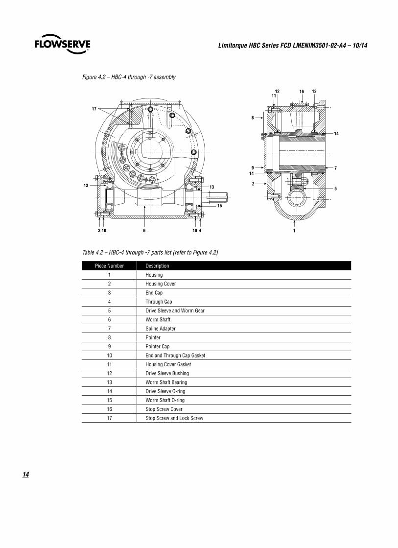
Figure 4.2 – HBC-4 through -7 assembly
17
15
14106103
11
14
8
9
2
147
5
16 12
13 13
12
Table 4.2 – HBC-4 through -7 parts list (refer to Figure 4.2)
Piece Number Description
1 Housing
2 Housing Cover
3 End Cap
4 Through Cap
5 Drive Sleeve and Worm Gear
6 Worm Shaft
7 Spline Adapter
8 Pointer
9 Pointer Cap
10 End and Through Cap Gasket
11 Housing Cover Gasket
12 Drive Sleeve Bushing
13 Worm Shaft Bearing
14 Drive Sleeve O-ring
15 Worm Shaft O-ring
16 Stop Screw Cover
17 Stop Screw and Lock Screw
15
Limitorque HBC Series FCD LMENIM3501-02-A4 – 10/14
flowserve.com
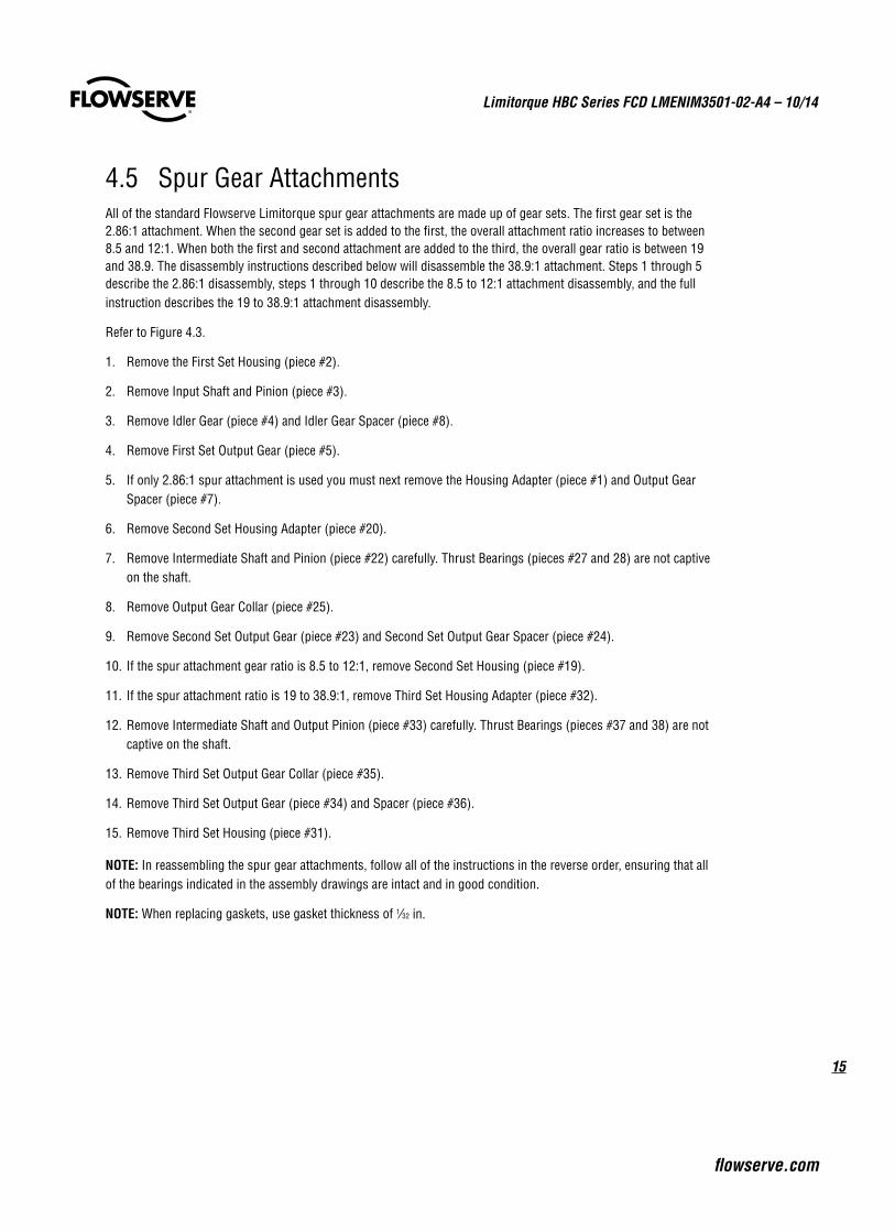
4.5 Spur Gear AttachmentsAll of the standard Flowserve Limitorque spur gear attachments are made up of gear sets. The first gear set is the 2.86:1 attachment. When the second gear set is added to the first, the overall attachment ratio increases to between 8.5 and 12:1. When both the first and second attachment are added to the third, the overall gear ratio is between 19 and 38.9. The disassembly instructions described below will disassemble the 38.9:1 attachment. Steps 1 through 5 describe the 2.86:1 disassembly, steps 1 through 10 describe the 8.5 to 12:1 attachment disassembly, and the full instruction describes the 19 to 38.9:1 attachment disassembly.
Refer to Figure 4.3.
1. Remove the First Set Housing (piece #2).
2. Remove Input Shaft and Pinion (piece #3).
3. Remove Idler Gear (piece #4) and Idler Gear Spacer (piece #8).
4. Remove First Set Output Gear (piece #5).
5. If only 2.86:1 spur attachment is used you must next remove the Housing Adapter (piece #1) and Output Gear Spacer (piece #7).
6. Remove Second Set Housing Adapter (piece #20).
7. Remove Intermediate Shaft and Pinion (piece #22) carefully. Thrust Bearings (pieces #27 and 28) are not captive on the shaft.
8. Remove Output Gear Collar (piece #25).
9. Remove Second Set Output Gear (piece #23) and Second Set Output Gear Spacer (piece #24).
10. If the spur attachment gear ratio is 8.5 to 12:1, remove Second Set Housing (piece #19).
11. If the spur attachment ratio is 19 to 38.9:1, remove Third Set Housing Adapter (piece #32).
12. Remove Intermediate Shaft and Output Pinion (piece #33) carefully. Thrust Bearings (pieces #37 and 38) are not captive on the shaft.
13. Remove Third Set Output Gear Collar (piece #35).
14. Remove Third Set Output Gear (piece #34) and Spacer (piece #36).
15. Remove Third Set Housing (piece #31).
NOTE: In reassembling the spur gear attachments, follow all of the instructions in the reverse order, ensuring that all of the bearings indicated in the assembly drawings are intact and in good condition.
NOTE: When replacing gaskets, use gasket thickness of 1⁄32 in.
Limitorque HBC Series FCD LMENIM3501-02-A4 – 10/14
16
Figure 4.3 – Spur gear attachments
2337
40
33
38 39
27
10
16
22
26 30 5
3
28
13
2 17
11
14
9
41
32
3534
29
31
36
5 22 28 299 212 30
26
27
13 11
3
10
16
17 14
20 23
24
19
25
4 15
128
183 16
1317 11
14 7
10
6
52 9 1
2337
40
33
38 39
27
10
16
22
26 30 5
3
28
13
2 17
11
14
9
41
32
3534
29
31
36
5 22 28 299 212 30
26
27
13 11
3
10
16
17 14
20 23
24
19
25
4 15
128
183 16
1317 11
14 7
10
6
52 9 1
Single reduction ratio – 2.86 to 11
Double reduction ratio – 12.00 to 1
17
Limitorque HBC Series FCD LMENIM3501-02-A4 – 10/14
flowserve.com
2337
40
33
38 39
27
10
16
22
26 30 5
3
28
13
2 17
11
14
9
41
32
3534
29
31
36
5 22 28 299 212 30
26
27
13 11
3
10
16
17 14
20 23
24
19
25
4 15
128
183 16
1317 11
14 7
10
6
52 9 1
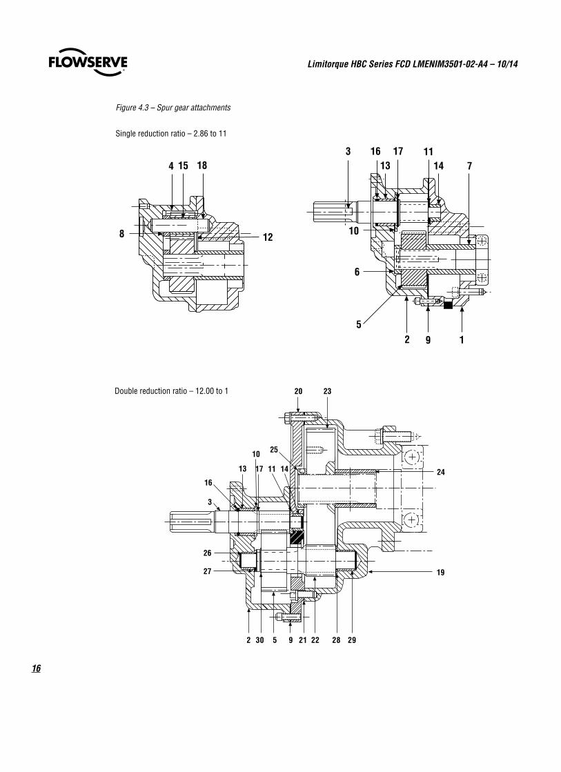
Figure 4.3 – Spur gear attachments (continued)
Triple reduction ratio – 38.90 to 1
Piece Number Description
1 First Set Housing Adapter
2 First Set Housing
3 First Set Input Shaft and Pinion
4 Idler Gear
5 First Set Output Gear
6 First Set Collar
7 First Set Output Gear Spacer
8 Idler Gear Spacer
9 First Set Housing Gasket
10 Input Shaft Thrust Bearing
11 Input Shaft Thrust Bearing
12 Idler Gear Thrust Bearing
13 First Set Housing Bearing
14 First Set Housing Adapter Bearing
15 Idler Gear Bearing
16 Input Shaft Quad Ring
17 Input Shaft Retaining Ring
18 Idler Gear Shaft
19 Second Set Housing
20 Second Set Housing Adapter
Piece Number Description
21 Second Set Housing Gasket
22 Intermediate Shaft and Pinion
23 Second Set Output Gear
24 Second Set Output Shaft Spacer
25 Second Set Output Gear Collar
26 Intermediate Shaft Bearing
27 Intermediate Shaft Thrust Bearing
28 Intermediate Shaft Thrust Bearing
29 Second Set Housing Bearing
30 Intermediate Shaft Retaining Ring
31 Third Set Housing
32 Third Set Housing Adapter
33 Intermediate Shaft and Output Pinion
34 Third Set Output Gear
35 Third Set Collar Output Gear
36 Third Set Output Shaft Spacer
37 Output Pinion and Shaft Thrust Bearing
38 Output Pinion and Shaft Thrust Bearing
39 Third Set Housing Bearing
40 Third Set Housing Adapter Bearing
41 Third Set Housing Gasket
Table 4.3 HBC-1 through -7 spur gear attachments parts list (refer to Figure 4.3)
Limitorque HBC Series FCD LMENIM3501-02-A4 – 10/14
18
a CAUTION: Following these instructions exactly will prevent jamming or damaging the equipment.
Complies fully with AWWA Standard C504, latest revision.
Refer to Figures 5.1 and 5.2.
1. Remove the Limit Stop Housing Cover (piece #9), Gear Frame Housing Cover (piece #10), and Gear Frame Through Cap (piece #11). Do not remove Gear Frame Retaining Plate (piece #48).
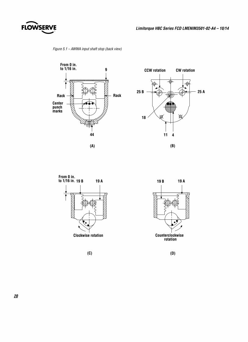
2. Note the position of the Racks (piece #19). The racks should be in the up position, as shown in Figure 5.1A.
3. Note the position of the three (3) center punch marks on the end of the Input Shaft (piece #4). These center punch marks show the position of the lug on the Lug Sleeve (piece #5).
4. With the input shaft as shown in Figure 5.1B, pull the Idler Gear (piece #18) and hold it out of engagement with the Input Pinion (piece #47).
5. Rotate the handwheel on the Input Shaft (piece #4) clockwise until the valve reaches the extreme position of travel. Normally with clockwise handwheel rotation closing the valve, the valve will go to the fully closed position. If the valve is set up for clockwise handwheel rotation to open, the valve will go to the fully open position.
6. Place the Input Shaft (piece #4) in position, as shown in Figure 5.1C.
7. Using a screwdriver, rotate the Input Pinion (piece #25A), as shown in Figure 5.1B clockwise until the Rack (piece #19A) moves downward, as shown in Figure 5.1C. Do not rotate the pinion any further.
8. Push Idler Gear (piece #18) into engagement and rotate Input Shaft (piece #4) clockwise to check the setting. The lug should hit the Rack (piece #19) and prevent further handwheel rotation.
5 Setting Instructions for AWWA Input Shaft Stop
19
Limitorque HBC Series FCD LMENIM3501-02-A4 – 10/14
flowserve.com
9. Reassemble the Gear Frame Through Cap (piece #11) with two mounting screws to hold the Idler Gear (piece #18) engaged with the Input Pinion (piece #25A) and rotate the Input Shaft (piece #4) counterclockwise to the other extreme valve position. If the Rack (piece #19B) should trip to the down position as shown in Figure 5.1D before the valve reaches the end of travel, use the following procedure:
a. Turn the Input Shaft (piece #4) back one turn.
b. Pull Idler Gear (piece #18) out of engagement.
c. Place a screwdriver on the Input Pinion (piece #25B).
d. Rotate clockwise approximately 50 turns.
e. Push Idler Gear (piece #18) into engagement again and rotate handwheel counterclockwise until the valve goes to the extreme position of travel. Repeat as necessary until the valve reaches the point where the stop should be set.
10. With the valve in the position to be set, position the Input Shaft (piece #4) as shown in Figure 5.1D, hold the Idler Gear (piece #18) out of engagement, and with the screwdriver on the Input Pinion (piece #25B), rotate it counterclockwise until the Rack (piece #19B) moves, as shown in Figure 5.1D. Do not rotate the pinion any further.
11. Push the Idler Gear (piece #18) into engagement and rotate Input Shaft (piece #4) counterclockwise to check setting. The lug should hit the Rack (piece #19B).
12. Reassemble Limit Stop Housing Cover (piece #9), Gear Frame Housing Cover (piece #10), and Gear Frame Through Cap (piece #11).
13. Open and close the valve fully to verify that position limit stops are set at the desired valve position.
NOTE: When the AWWA input shaft stop is supplied, the standard limit stops in the housing are also furnished. The housing limit stops should be adjusted to function as secondary stops by ensuring that the AWWA input stops engage first. Section 2 – Inspection, Installation, and Mounting Procedures in this manual provides instruction for setting the standard housing limit stops.
Limitorque HBC Series FCD LMENIM3501-02-A4 – 10/14
20
Figure 5.1 – AWWA input shaft stop (back view)
Clockwise rotation
19 B 19 A
Counterclockwiserotation
19 B 19 A
(C) (D)
From 0 in.to 1/16 in.
Rack
Centerpunchmarks
44
9 CCW rotation CW rotation
25 A25 B
18
411
(A) (B)
From 0 in.to 1/16 in.
Rack
21
Limitorque HBC Series FCD LMENIM3501-02-A4 – 10/14
flowserve.com
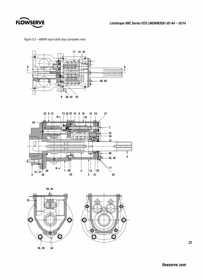
Figure 5.2 – AWWA input shaft stop (complete view)
23 129
26
13 43 22 15 1016
51 27
7
24
18
31
3
36, 40
37, 4130
20
8
46129
5
53
214 28
52
11
45, 42
48
B
B
44
19
39, 34
17 47, 25
49, 50
3238, 426
A
4
A
21

Limitorque HBC Series FCD LMENIM3501-02-A4 – 10/14
22
Piece Number Description
1 Limit Stop Housing
2 Gear Frame
3 Limit Stop Housing Adapter
4 Input Shaft
5 Splined Lug Sleeve
6 Intermittent Gear Shaft
7 Intermittent Pinion Shaft
8 Intermittent Drive Shaft
9 Limit Stop Housing Cover
10 Gear Frame Housing Cover
11 Gear Frame Through Cap
12 Rack Pinion
13 Pinion
14 Input Gear
15 Intermittent Stem Pinion
16 Intermittent Pinion
17 Intermittent Gear
18 Idler Gear
19 Rack
20 Flanged Bushing
21 Input Shaft Bushing
22 Intermittent Stem Pinion Bearing
23 Rack Pinion Bearing
24 Bushing
25 Input Pinion
26 Housing Cover Gasket
27 Gear Frame Cover Gasket
Piece Number Description
28 Through Cap Gasket
29 Housing Gasket
30 Adapter Gasket
31 O-ring
32 Bushing
34 Cap Screw Round Head #10 — 32 in x ½ in long
35 Roll Pin 3⁄32 in Diameter x ¾ in Long — Not Shown
36 Cap Screw Hex Head 5⁄16 in — 18 in x 1 in Long
37 Cap Screw Socket Head 3⁄8 in — 16 x 1½ in Long
38 Cap Screw Socket Head ¼ in — 20 in x ¾ in Long
39 Lockwasher #10
40 Lockwasher 5⁄16 in
41 Lockwasher 3⁄8 in
42 Lockwasher ¼ in
43 Roll Pin 1⁄8 in Diameter x 5⁄8 in Long
44 1 in — 20 Drain Plug
45 Cap Screw Round Head ¼ in — 20 x ½ in Long
46 Dowel Pin ¼ in Diameter x 5⁄8 in Long
47 Input Pinion — Gear Assembly
48 Gear Frame Retaining Plate
49 ¼ in — 20 x 7⁄16 in Long Socket Head Cap Screw
50 ¼ in Lockwasher Hi-Collar
51 Pinion Spacer
52 Through Cap Gasket
53 Idler Gear Spacer
Note: When the AWWA input shaft stop is used, the standard limit stop is also furnished.
Table 5.1 – AWWA input shaft stop parts list (refer to Figure 5.2)
23
Limitorque HBC Series FCD LMENIM3501-02-A4 – 10/14
flowserve.com
6 How to Order Parts
To order parts or obtain further information about your Flowserve Limitorque HBC gearboxes, contact your local Limitorque distributor sales office, or:
Flowserve Limitorque 5114 Woodall Road P.O. Box 11318 Lynchburg, VA 24506-1318
Telephone (434) 528-4400 Fax (434) 845-9736
All inquiries or orders must be accompanied by the following information:
1. Gearbox size2. Order number3. Serial number
flowserve.com
FCD LMENIM3501-02-A4 Printed in USA. October 2014
To find your local Flowserve Limitorque representative, visit www.limitorque.com or call USA 1 800 528 4400.
Flowserve CorporationFlow Control
United StatesFlowserve Limitorque5114 Woodall Road P.O. Box 11318Lynchburg, VA 24506-1318Phone: 434-528-4400Fax: 434-845-9736
EnglandFlowserve LimitorqueEuro HouseAbex RoadNewburyBerkshire, RG14 5EYUnited KingdomPhone: 44-1-635-46999Fax: 44-1-635-36034
SingaporeLimitorque Asia, Pte., Ltd.12, Tuas Avenue 20Singapore 638824Phone: 65-6868-4628Fax: 65-6862-4940
ChinaLimitorque Beijing, Pte., Ltd.RM A1/A222/F, East Area, Hanwei PlazaNo. 7 Guanghua Road, Chaoyang DistrictBeijing 100004, Peoples Republic of ChinaPhone: 86-10-5921-0606Fax: 86-10-6561-2702
IndiaFlowserve LimitorquePlot No. #4, 1 A, Road No. 8, EPIPWhitefield, Bangalore – 560066KarnatakaIndiaPhone: 91-80-40146200Fax: 91-80-28410286
ItalyFlowserve LimitorqueFluid Power SystemsVia Rio Vallone 1720883 Mezzago MBItalyPhone: 39-039-620601Fax: 39-039-62060 213
Flowserve Corporation has established industry leadership in the design and manufacture of its products. When properly selected, this Flowserve product is designed to perform its intended function safely during its useful life. However, the purchaser or user of Flowserve products should be aware that Flowserve products might be used in numerous applications under a wide variety of industrial service conditions. Although Flowserve can (and often does) provide general guidelines, it cannot provide specific data and warnings for all possible applications. The purchaser/user must therefore assume the ultimate responsibility for the proper sizing and selection, installation, operation and maintenance of Flowserve products. The purchaser/user should read and understand the Installation Operation Maintenance (IOM) instructions included with the product, and train its employees and contractors in the safe use of Flowserve products in connection with the specific application.
While the information and specifications contained in this literature are believed to be accurate, they are supplied for informative purposes only and should not be considered certified or as a guarantee of satisfactory results by reliance thereon. Nothing contained herein is to be construed as a warranty or guarantee, express or implied, regarding any matter with respect to this product. Because Flowserve is continually improving and upgrading its product design, the specifications, dimensions and information contained herein are subject to change without notice. Should any question arise concerning these provisions, the purchaser/user should contact Flowserve Corporation at any one of its worldwide operations or offices.
© 2014 Flowserve Corporation, Irving, Texas, USA. Flowserve is a registered trademark of Flowserve Corporation.