machine safeguarding at the point of operation
TRANSCRIPT
Mac hine Safeguard ing at the Po in t o f Operat ion
A Guide for Finding Solutions to Machine Hazards

About t h is doc um entMachine Safeguarding at the Point of Operation is an Oregon OSHA Standards and Technical Resources Section publication.
Thanks to the following individuals:
Layout and design: Patricia Young, Oregon OSHA
Editing and proo¿ng: Mark Peterson, DCBS Communications
Quest ions or c om m ent s? We’d like to hear from you.
• Technical questions about this publication?
Contact Ken Langley: 503-947-7454, [email protected]
Contact Craig Hamelund: 971-673-2875, [email protected]
• Comments or suggestions for improving this guide?
Contact Stephanie Ficek: 503-947-7389, stephanie.j.¿[email protected]
Piracy notice: Reprinting, excerpting, or plagiarizing this publication is ¿ne with us as long as it’s not for pro¿t! Please inform Oregon OSHA of your intention as a courtesy.
Above: Be Careful Near Machinery poster, created by Robert Lachenmann (1936) for the Federal Art Project. Source: Library of Congress: Prints and Photographs Online Catalogue.

Mac hine Safeguard ing at the Po int o f Operat ion
A Guide for Finding Solutions to Machine Hazards

2
Table o f Cont ent s
The im por t anc e of m ac hine safeguar ding . . . . . . . . . . . . . . . . . . . . . . . . . . . . . . . .4
Abras ive w heel g r inder . . . . . . . . . . . . . . . . . . . . . . . . . . . . . . . . . . . . . . . . . . . . . . . . .6
Hor izont a l band saw . . . . . . . . . . . . . . . . . . . . . . . . . . . . . . . . . . . . . . . . . . . . . . . . . . .9
Ver t ic a l band saw . . . . . . . . . . . . . . . . . . . . . . . . . . . . . . . . . . . . . . . . . . . . . . . . . . . . .10
CNC t ur n ing m ac hine. . . . . . . . . . . . . . . . . . . . . . . . . . . . . . . . . . . . . . . . . . . . . . . . . .11
Com pac t ing and ba l ing equipm ent . . . . . . . . . . . . . . . . . . . . . . . . . . . . . . . . . . . . .14
Cut -o f f saw s . . . . . . . . . . . . . . . . . . . . . . . . . . . . . . . . . . . . . . . . . . . . . . . . . . . . . . . . . .16
Dr i l l press . . . . . . . . . . . . . . . . . . . . . . . . . . . . . . . . . . . . . . . . . . . . . . . . . . . . . . . . . . . .18
I ronw or ker . . . . . . . . . . . . . . . . . . . . . . . . . . . . . . . . . . . . . . . . . . . . . . . . . . . . . . . . . . .19
J oint er . . . . . . . . . . . . . . . . . . . . . . . . . . . . . . . . . . . . . . . . . . . . . . . . . . . . . . . . . . . . . . .20
Met al lat he . . . . . . . . . . . . . . . . . . . . . . . . . . . . . . . . . . . . . . . . . . . . . . . . . . . . . . . . . . .21
Wood lat he . . . . . . . . . . . . . . . . . . . . . . . . . . . . . . . . . . . . . . . . . . . . . . . . . . . . . . . . . . .23
Mi l l ing m ac hine . . . . . . . . . . . . . . . . . . . . . . . . . . . . . . . . . . . . . . . . . . . . . . . . . . . . . . .25
Planer . . . . . . . . . . . . . . . . . . . . . . . . . . . . . . . . . . . . . . . . . . . . . . . . . . . . . . . . . . . . . . .26
Plast ic in jec t ion m old ing . . . . . . . . . . . . . . . . . . . . . . . . . . . . . . . . . . . . . . . . . . . . . .27
Por t ab le abras ive g r inder . . . . . . . . . . . . . . . . . . . . . . . . . . . . . . . . . . . . . . . . . . . . . .28
Por t ab le bel t sander . . . . . . . . . . . . . . . . . . . . . . . . . . . . . . . . . . . . . . . . . . . . . . . . . .29
Por t ab le c i r c u lar saw . . . . . . . . . . . . . . . . . . . . . . . . . . . . . . . . . . . . . . . . . . . . . . . . .30
Por t ab le j igsaw . . . . . . . . . . . . . . . . . . . . . . . . . . . . . . . . . . . . . . . . . . . . . . . . . . . . . . .32
Pow er press . . . . . . . . . . . . . . . . . . . . . . . . . . . . . . . . . . . . . . . . . . . . . . . . . . . . . . . . . .33
Pow er press brake . . . . . . . . . . . . . . . . . . . . . . . . . . . . . . . . . . . . . . . . . . . . . . . . . . . .38

3
Pow er ro l l for m ing and bending m ac hine . . . . . . . . . . . . . . . . . . . . . . . . . . . . . . . .42
Radia l -ar m saw . . . . . . . . . . . . . . . . . . . . . . . . . . . . . . . . . . . . . . . . . . . . . . . . . . . . . . .44
Robot s . . . . . . . . . . . . . . . . . . . . . . . . . . . . . . . . . . . . . . . . . . . . . . . . . . . . . . . . . . . . . . .45
Bel t sander . . . . . . . . . . . . . . . . . . . . . . . . . . . . . . . . . . . . . . . . . . . . . . . . . . . . . . . . . . .47
Disk sander . . . . . . . . . . . . . . . . . . . . . . . . . . . . . . . . . . . . . . . . . . . . . . . . . . . . . . . . . .48
Sc ro l l (j ig ) saw . . . . . . . . . . . . . . . . . . . . . . . . . . . . . . . . . . . . . . . . . . . . . . . . . . . . . . .50
Shaper /rout er . . . . . . . . . . . . . . . . . . . . . . . . . . . . . . . . . . . . . . . . . . . . . . . . . . . . . . . . .51
Shear . . . . . . . . . . . . . . . . . . . . . . . . . . . . . . . . . . . . . . . . . . . . . . . . . . . . . . . . . . . . . . . .53
Table saw . . . . . . . . . . . . . . . . . . . . . . . . . . . . . . . . . . . . . . . . . . . . . . . . . . . . . . . . . . . .55
Guard ing pow er-t ransm iss ion apparat uses . . . . . . . . . . . . . . . . . . . . . . . . . . . . . .57
Loc kout /t agout . . . . . . . . . . . . . . . . . . . . . . . . . . . . . . . . . . . . . . . . . . . . . . . . . . . . . . .58
Risk -reduc t ion h ierarc hy . . . . . . . . . . . . . . . . . . . . . . . . . . . . . . . . . . . . . . . . . . . . . .59
Tra in ing guide l ines . . . . . . . . . . . . . . . . . . . . . . . . . . . . . . . . . . . . . . . . . . . . . . . . . . . .61
Basic safet y pr inc ip les . . . . . . . . . . . . . . . . . . . . . . . . . . . . . . . . . . . . . . . . . . . . . . . .62
Glossar y of t er m s . . . . . . . . . . . . . . . . . . . . . . . . . . . . . . . . . . . . . . . . . . . . . . . . . . . . .63
Oregon OSHA Ser v ic es . . . . . . . . . . . . . . . . . . . . . . . . . . . . . . . . . . . . . . . . . . . . . . . .64
Table o f Cont ent s
4
T he im por t anc e of m ac hine safeguard ingMost of us have heard the old adage about how machinery doesn’t discriminate between product and people – it will do the same to both. Many people discover this through unfortunate means: an injured machine operator sharing the details of his or her accident or a family member reÀecting on the circumstances that took a loved one.
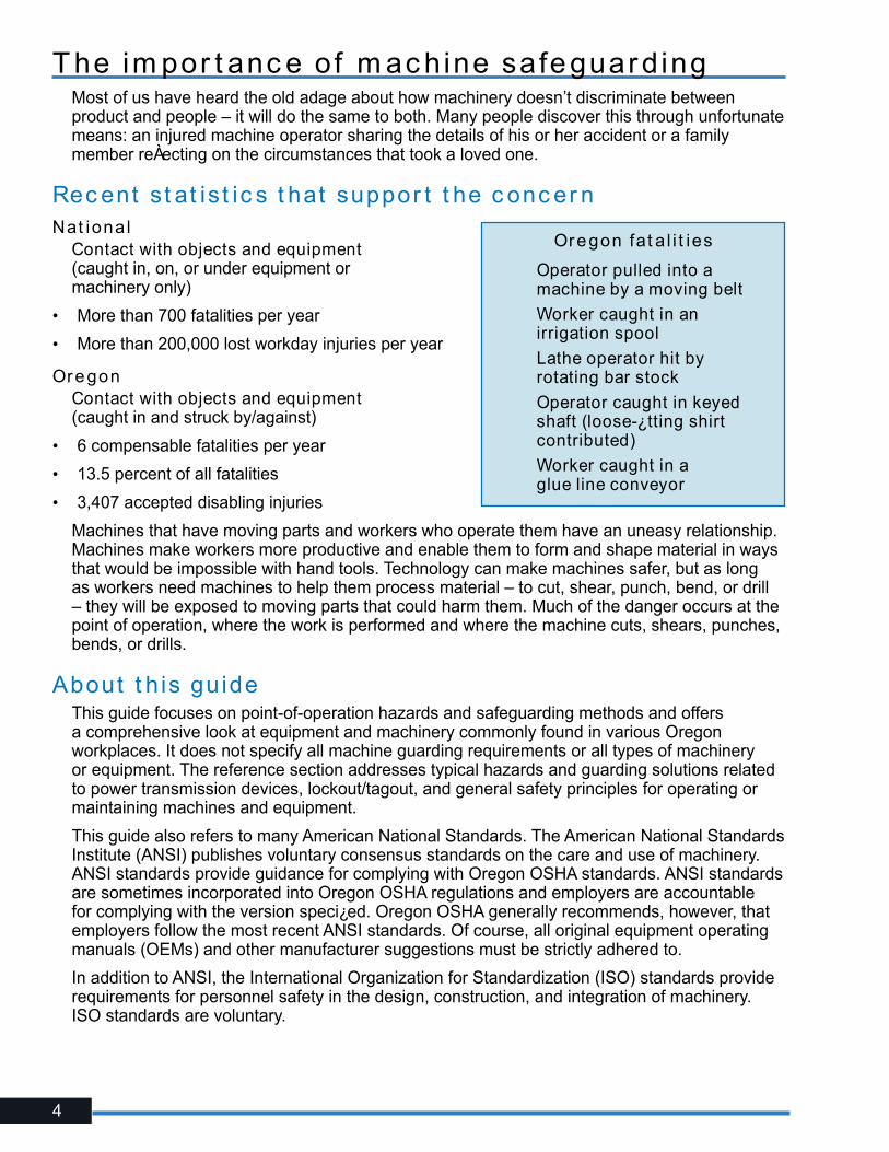
Rec ent s t at is t ic s t hat suppor t t he c onc er nNat ional
Contact with objects and equipment (caught in, on, or under equipment or machinery only)
• More than 700 fatalities per year
• More than 200,000 lost workday injuries per year
Oregon Contact with objects and equipment (caught in and struck by/against)
• 6 compensable fatalities per year
• 13.5 percent of all fatalities
• 3,407 accepted disabling injuries
Machines that have moving parts and workers who operate them have an uneasy relationship. Machines make workers more productive and enable them to form and shape material in ways that would be impossible with hand tools. Technology can make machines safer, but as long as workers need machines to help them process material – to cut, shear, punch, bend, or drill – they will be exposed to moving parts that could harm them. Much of the danger occurs at the point of operation, where the work is performed and where the machine cuts, shears, punches, bends, or drills.
About t h is gu ideThis guide focuses on point-of-operation hazards and safeguarding methods and offers a comprehensive look at equipment and machinery commonly found in various Oregon workplaces. It does not specify all machine guarding requirements or all types of machinery or equipment. The reference section addresses typical hazards and guarding solutions related to power transmission devices, lockout/tagout, and general safety principles for operating or maintaining machines and equipment.
This guide also refers to many American National Standards. The American National Standards Institute (ANSI) publishes voluntary consensus standards on the care and use of machinery. ANSI standards provide guidance for complying with Oregon OSHA standards. ANSI standards are sometimes incorporated into Oregon OSHA regulations and employers are accountable for complying with the version speci¿ed. Oregon OSHA generally recommends, however, that employers follow the most recent ANSI standards. Of course, all original equipment operating manuals (OEMs) and other manufacturer suggestions must be strictly adhered to.
In addition to ANSI, the International Organization for Standardization (ISO) standards provide requirements for personnel safety in the design, construction, and integration of machinery. ISO standards are voluntary.
Oregon fat a l i t ies
� Operator pulled into a machine by a moving belt
� Worker caught in an irrigation spool
� Lathe operator hit by rotating bar stock
� Operator caught in keyed shaft (loose-¿tting shirt contributed)
� Worker caught in a glue line conveyor
5
Oregon OSHA st andards re lat ed t o m ac hiner y and m ac hine guard ingGeneral Indust r y� Division 2/Subdivision I, Personal Protective Equipment
� Division 2/Subdivision J, General Environmental Controls (Lockout/Tagout)
� Division 2/Subdivision N, Material Handling and Storage
� Division 2/Subdivision O, Machinery and Machine Guarding
� Division 2/Subdivision P, Hand and Portable Powered Tools
� Division 2/Subdivision R, Special Industries (sawmills, pulp and paper mills, etc.)
� Oregon OSHA Program Directive A-280, National Emphasis Program on Amputations
Const r uc t ion� Division 3/Subdivision E, Personal Protective and Life Saving Equipment
� Division 3/Subdivision I, Tools — Hand and Power
Agr ic u l t ure� Division 4/Subdivision I, Protective Equipment
� Division 4/Subdivision J, Work Environment (Lockout/Tagout)
� Division 4/Subdivision N, Material Handling
� Division 4/Subdivision O, Equipment Guarding
� Division 4/Subdivision P, Small Tools
Forest Ac t iv i t ies� Division 7/Subdivision D, Personal Protective Equipment and Programs
� Division 7/Subdivision H, Machines Used in Forest Activities
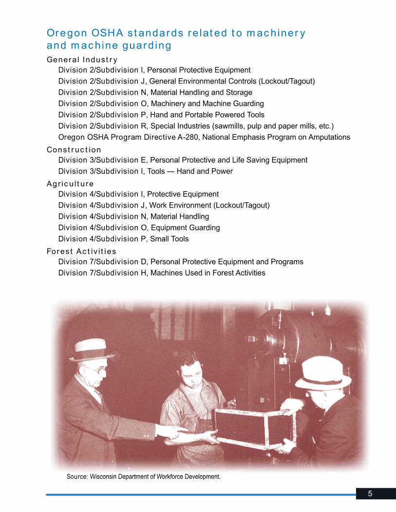
Source: Wisconsin Department of Workforce Development.
6
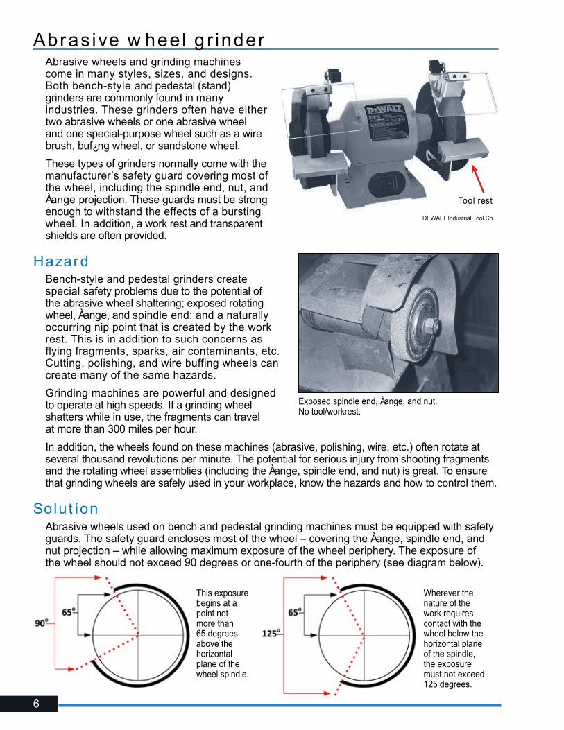
Abras ive w heel g r inder Abrasive wheels and grinding machines come in many styles, sizes, and designs. Both bench-style and pedestal (stand) grinders are commonly found in many industries. These grinders often have either two abrasive wheels or one abrasive wheel and one special-purpose wheel such as a wire brush, buf¿ng wheel, or sandstone wheel.
These types of grinders normally come with the manufacturer’s safety guard covering most of the wheel, including the spindle end, nut, and Àange projection. These guards must be strong enough to withstand the effects of a bursting wheel. In addition, a work rest and transparent shields are often provided.
HazardBench-style and pedestal grinders create special safety problems due to the potential of the abrasive wheel shattering; exposed rotating wheel, Àange, and spindle end; and a naturally occurring nip point that is created by the work rest. This is in addition to such concerns as flying fragments, sparks, air contaminants, etc. Cutting, polishing, and wire buffing wheels can create many of the same hazards.
Grinding machines are powerful and designed to operate at high speeds. If a grinding wheel shatters while in use, the fragments can travel at more than 300 miles per hour.
In addition, the wheels found on these machines (abrasive, polishing, wire, etc.) often rotate at several thousand revolutions per minute. The potential for serious injury from shooting fragments and the rotating wheel assemblies (including the Àange, spindle end, and nut) is great. To ensure that grinding wheels are safely used in your workplace, know the hazards and how to control them.
Solut ionAbrasive wheels used on bench and pedestal grinding machines must be equipped with safety guards. The safety guard encloses most of the wheel – covering the Àange, spindle end, and nut projection – while allowing maximum exposure of the wheel periphery. The exposure of the wheel should not exceed 90 degrees or one-fourth of the periphery (see diagram below).
DEWALT Industrial Tool Co.
Tool rest
Exposed spindle end, Àange, and nut. No tool/workrest.
This exposure begins at a point not more than 65 degrees above the horizontal plane of the wheel spindle.
Wherever the nature of the work requires contact with the wheel below the horizontal plane of the spindle, the exposure must not exceed 125 degrees.

7
Because the safety guard is designed to restrain the pieces of a shattered grinding wheel, the distance between the safety guard and the top periphery of the wheel must not be more than ¼ inch. If this distance is greater because of the decreased size of the abrasive wheel, then a “tongue guard” must be installed to protect workers from Àying fragments in case of wheel breakage. This “tongue guard” should be adjustable to maintain the maximum ¼ inch distance between it and the wheel.
An adjustable work rest must also be installed and maintained at a maximum clearance of 1/8 inch between it and the face of the wheel.
In addition to offering a stable working position, this small clearance must be maintained to prevent the operator’s hands or the work from being jammed between the wheel and the rest, which may cause serious injury or the wheel to break.
All abrasive wheels must be closely inspected and ring-tested before mounting to ensure that they are free from cracks or other defects. Wheels should be suspended from the center mounting hole and tapped gently with a light, nonmetallic instrument. A stable and undamaged wheel will give a clear metallic tone or “ring.” If a wheel sounds dead or dull, it may be cracked. Do not use it. This is known as the “ring test.”
The spindle speed of the machine must also be checked before mounting the wheel to be certain that it does not exceed the maximum operating speed marked on the wheel.
Always follow the manufacturer’s recommendations.
Referenc esGeneral Indust r y � Oregon OSHA Division 2/Subdivision O, 1910.215
Const r uc t ion � Oregon OSHA Division 3/Subdivision I, 1926.300(b)(7) & 1926.303
Agr ic u l t ure � Oregon OSHA Division 4/Subdivision O, OAR 437-004-2100
Am er ic an Nat ional St andards Inst i t u t e� ANSI B7.1 Safety Code for the Use, Care, and Protection of Abrasive Wheels
� ANSI B11.9 Safety Requirements for Grinding Machines
• Proper exposure angle (90°)• Adjustable “tongue guards” (1⁄4”)• Adjustable tool/work rest (1⁄8”)
Plastic glass (Plexiglas) shields are optional. They are not a substitute for eye and face protection and are not included as a part of the guard (unless they are adjusted accordingly and have strength equal to that of the safety guard).
Tool rest
Spindle guard
Tongue guard

8

9
Hor izont a l band sawA horizontal band saw uses a thin, Àexible, continuous metal band with cutting teeth on one edge. Horizontal band saws are used primarily for cutting metal stock, such as angle iron and other round and Àat stock. The blade runs horizontally on two pulleys through two separate guides.
The operator secures the stock on the table and manually assists the saw as it cuts.
HazardSerious cuts or amputations can occur if the operator contacts the blade. Extreme caution is necessary because the operator’s hands may come close to the saw blade, and the entire run of the blade cannot be fully guarded.
Solut ionGuard the entire blade, except at the point of operation (the working portion of the blade between the two guides). Band saw wheels must be fully encased.
Make sure the saw includes a tension-control device to indicate proper blade tension.
Referenc esGeneral Indust r y��Oregon OSHA Division 2/Subdivision O,
1910.212 – General Requirements for All Machines
Am er ic an Nat ional St andards Inst i t u t e��ANSI B11.10 – Metal Sawing Machines
RL Johnson Co.
Horizontal band saw blade guard.
10
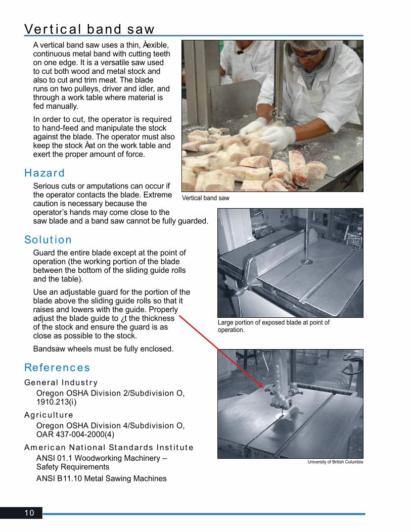
Ver t ic a l band sawA vertical band saw uses a thin, Àexible, continuous metal band with cutting teeth on one edge. It is a versatile saw used to cut both wood and metal stock and also to cut and trim meat. The blade runs on two pulleys, driver and idler, and through a work table where material is fed manually.
In order to cut, the operator is required to hand-feed and manipulate the stock against the blade. The operator must also keep the stock Àat on the work table and exert the proper amount of force.
HazardSerious cuts or amputations can occur if the operator contacts the blade. Extreme caution is necessary because the operator’s hands may come close to the saw blade and a band saw cannot be fully guarded.
Solut ionGuard the entire blade except at the point of operation (the working portion of the blade between the bottom of the sliding guide rolls and the table).
Use an adjustable guard for the portion of the blade above the sliding guide rolls so that it raises and lowers with the guide. Properly adjust the blade guide to ¿t the thickness of the stock and ensure the guard is as close as possible to the stock.
Bandsaw wheels must be fully enclosed.
Referenc esGeneral Indust r y� Oregon OSHA Division 2/Subdivision O,
1910.213(i)
Ag r ic u l t ure� Oregon OSHA Division 4/Subdivision O,
OAR 437-004-2000(4)
Am er ic an Nat ional St andards Inst i t u t e� ANSI 01.1 Woodworking Machinery –
Safety Requirements
� ANSI B11.10 Metal Sawing Machines
Large portion of exposed blade at point of operation.
University of British Columbia
Vertical band saw

11
CNC t ur n ing m ac hineComputer numerically controlled (CNC) machining centers cut and shape an assortment of precision products from automobile parts to general machine parts. Operating in either horizontal or vertical positions, CNC machinery includes machining tools such as lathes, multi-axis spindles, and milling and boring machines; the functions formerly performed by human operators are performed by a computer-control module. CNC machinery is either hand loaded or automatically fed.
Most CNC machinery is partially or totally enclosed by metal enclosures equipped with thermoplastic vision panels, most commonly polycarbonate.
HazardTwo primary hazards arise from CNC turning operations: Entanglement and the ejection of parts. Serious lacerations, fractures, amputations, or even death can occur if an operator contacts or becomes entangled in or between the tooling or rotating work piece. Similar injuries or death can also occur from being struck by ejected parts (e.g., cutters or other tools, chucks, or the work piece).
Although the risk of injury from ejected parts is lessened due to the interlocked enclosure of CNC machinery, recent research has shown that polycarbonate materials used in the unit’s vision panels can degrade after exposure to the metalworking Àuids and lubricants used in the machining process.
Over time, vision panels may not be able to contain ejected parts. Most ejections at CNC turning machines are caused by a setup error or failing to properly maintain work-holding devices.
Unexpected movement or startup caused by faults in the control system can also cause serious injury.
Solut ionTo prevent access into the point-of-operation area, ensure the CNC machine is fully enclosed and equipped with an interlocked guard (door). The cutting tools should not start unless the door is in a closed position and should stop when the door is opened. Many machines lock the guard in position during operation and can only be opened when the tooling stops. If access into the point of operation is infrequent, install a ¿xed enclosure that can be removed only for maintenance activities.
CNC control panel
12
Automatic loading and unloading methods and automatic tool changing further reduce the exposure to the point of operation.
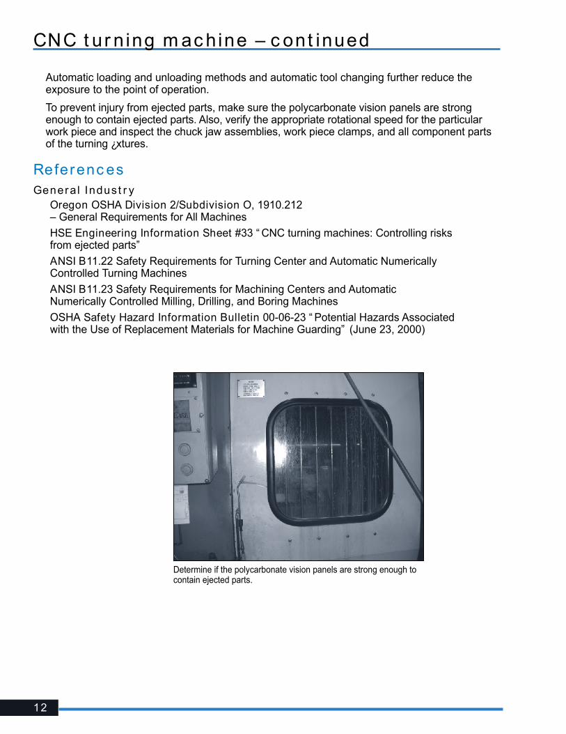
To prevent injury from ejected parts, make sure the polycarbonate vision panels are strong enough to contain ejected parts. Also, verify the appropriate rotational speed for the particular work piece and inspect the chuck jaw assemblies, work piece clamps, and all component parts of the turning ¿xtures.
Referenc esGeneral Indust r y� Oregon OSHA Division 2/Subdivision O, 1910.212
– General Requirements for All Machines
� HSE Engineering Information Sheet #33 “ CNC turning machines: Controlling risks from ejected parts”
� ANSI B11.22 Safety Requirements for Turning Center and Automatic Numerically Controlled Turning Machines
� ANSI B11.23 Safety Requirements for Machining Centers and Automatic Numerically Controlled Milling, Drilling, and Boring Machines
� OSHA Safety Hazard Information Bulletin 00-06-23 “ Potential Hazards Associated with the Use of Replacement Materials for Machine Guarding” (June 23, 2000)
Determine if the polycarbonate vision panels are strong enough to contain ejected parts.
CNC t ur n ing m ac hine – c ont inued
13

14
Com pac t ing and ba l ing equipm entCompacting and baling equipment reduces large amounts of solid waste to smaller, more manageable units by means of powered rams. In general, compactors compress refuse into containers for transport. Baling equipment is designed to compress material (e.g., cardboard boxes) and produce a bale (bound or unbound) that is handled as a unit.
A wide range of hazards exist simply due to the size, con¿guration, and operation of compactors and balers. Some machines allow direct access to the compression chamber, while others have a hopper or chute through which material feeds into the machine. Machines may operate in a manual, semiautomatic, or automatic mode. The rams may move vertically or horizontally.
HazardWorkers can be crushed by the ram motion if guarding is missing or bypassed, or if lockout procedures are not followed during maintenance activities. Older compacting equipment may not have appropriate interlock guarding or may not have enough guarding to enclose the chamber or point-of-operation area completely.
Severe injury and death can also occur during service or maintenance tasks on or inside an energized or jammed machine if the machine cycles automatically or if the machine is activated by another worker who is unaware that someone is inside the chamber. Because ram motion stops during a jam, workers may not recognize that the machine remains energized and that the ram could activate unexpectedly. Similarly, if conveyors are used to feed material into a compactor or baler, workers may mistakenly believe that shutting down the conveyor also prevents the compactor or baler from operating.
In addition to the hazardous-energy potential, working inside these machines may also present con¿ned-space hazards such as hazardous atmospheres and engulfment.
Solut ionAccess covers and point-of-operation guarding must be interlocked in such a manner that the compactor cannot be operated if the guard or loading door is removed or opened. Most compactors and balers today prevent workers from reaching into the point of operation by con¿guration, cycling controls, and interlock guarding that interrupt or reverse the ram’s motion if the compression chamber doors are opened. However, older equipment may not have these features and it would be wise to consult with the manufacturer for possible retro¿ts or upgrades.
Whenever unjamming, adjusting, cleaning, repairing, or performing other maintenance tasks, the machine must be isolated from all its energy sources and “locked out.” If conveyors are used, they should be interconnected so that a single, lockable device can de-energize and isolate the power to both machines. Lockout procedures are further explained on Page 58.
Follow permit-required con¿ned space entry procedures whenever working inside these machines.
Also, refer to Oregon OSHA’s rules for Stationary Compactors, Self-Contained Compactors, and Balers for speci¿c control, marking, and signage requirements.
Paci¿c Compactor Corporation

15
Referenc esGeneral Indust r y� Oregon OSHA Division 2/Subdivision O, OAR 437-002-0256 — Stationary Compactors,
Self-Contained Compactors, and Balers
� Oregon OSHA Division 2/Subdivision J, 1910.147 — The Control of Hazardous Energy (Lockout/Tagout)
� Oregon OSHA Division 2/Subdivision J, 437-002-0146 — Con¿ned Spaces
� ANSI Z245.2 Stationary Compactors — Safety Requirements
� ANSI Z245.5 Baling Equipment — Safety Requirements
� NIOSH Publication No. 2003-124 Preventing Deaths and Injuries While Compacting or Baling Refuse Material
16
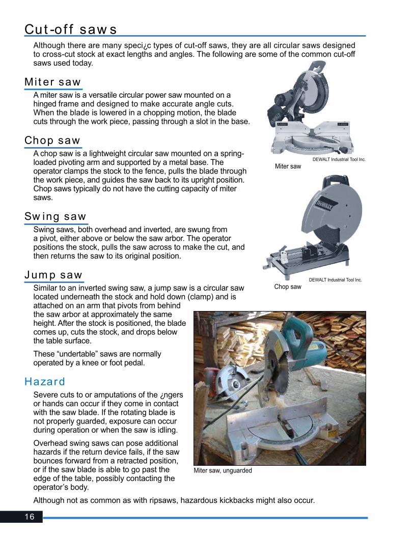
Miter saw, unguarded
Cut -of f saw sAlthough there are many speci¿c types of cut-off saws, they are all circular saws designed to cross-cut stock at exact lengths and angles. The following are some of the common cut-off saws used today.
Mi t er sawA miter saw is a versatile circular power saw mounted on a hinged frame and designed to make accurate angle cuts. When the blade is lowered in a chopping motion, the blade cuts through the work piece, passing through a slot in the base.
Chop saw A chop saw is a lightweight circular saw mounted on a spring-loaded pivoting arm and supported by a metal base. The operator clamps the stock to the fence, pulls the blade through the work piece, and guides the saw back to its upright position. Chop saws typically do not have the cutting capacity of miter saws.
Sw ing sawSwing saws, both overhead and inverted, are swung from a pivot, either above or below the saw arbor. The operator positions the stock, pulls the saw across to make the cut, and then returns the saw to its original position.
J um p saw Similar to an inverted swing saw, a jump saw is a circular saw located underneath the stock and hold down (clamp) and is attached on an arm that pivots from behind the saw arbor at approximately the same height. After the stock is positioned, the blade comes up, cuts the stock, and drops below the table surface.
These “undertable” saws are normally operated by a knee or foot pedal.
HazardSevere cuts to or amputations of the ¿ngers or hands can occur if they come in contact with the saw blade. If the rotating blade is not properly guarded, exposure can occur during operation or when the saw is idling.
Overhead swing saws can pose additional hazards if the return device fails, if the saw bounces forward from a retracted position, or if the saw blade is able to go past the edge of the table, possibly contacting the operator’s body.
Although not as common as with ripsaws, hazardous kickbacks might also occur.
DEWALT Industrial Tool Inc.
Miter saw
DEWALT Industrial Tool Inc.
Chop saw

17
Overhead swing saw missing a lower blade guard and extending beyond table edge.
Missing “nose guard” on a jump saw.
Solut ionOvertable cut-off saws (miter, chop, and overhead swing saws) must be provided with ¿xed hood guards that enclose the arbor and top half of the saw. These saws also must be equipped with a self-adjusting lower blade guard that automatically adjusts itself to the thickness of the material being cut and provides continuous protection from the blade. Most guards supplied by manufacturers are designed to move out of the way as the blade nears the cut. If a guard seems slow to return to its normal position, adjust or repair it immediately.
Overhead swing saws must be provided with a device (i.e., counterweight) to return the saw automatically to the back of the table when released at any point of its travel. Limit chains must also be provided to keep the saw from swinging beyond the front or back edges of the table.
Inverted (undertable) swing saws and jump saws, when idling, are guarded by their enclosure.
During operation, a hood-type guard or clamping means must be provided for the blade portion that protrudes above the table or above the stock being cut in addition to holding down the stock.
These saws must have a “nose guard” af¿xed to the saw table in front of the hood guard (or another method providing equivalent protection) to prevent accidental entry of ¿ngers or hands into the path of the saw blade from the front (Oregon OSHA Hazard Alert, “Nose Guards,” applicable for cut-off, inverted swing cut-off, and similar saws).
Referenc esGeneral Indust r y� Oregon OSHA Division 2/Subdivision O,
1910.213(g) – Swing saw
� Oregon OSHA Division 2/Subdivision O, 1910.213(h)(1) – Miter/chop saw
Const r uc t ion� Oregon OSHA Division 3/Subdivision I,
1926.304(g)(1) – Miter/chop saw
Agr ic u l t ure� Oregon OSHA Division 4/Subdivision O,
OAR 437-004-2000(5)
Am er ic an Nat ional St andards Inst i t u t e� ANSI O1.1 – Woodworking Machinery – Safety Requirements
Properly guarded jump saw.
18
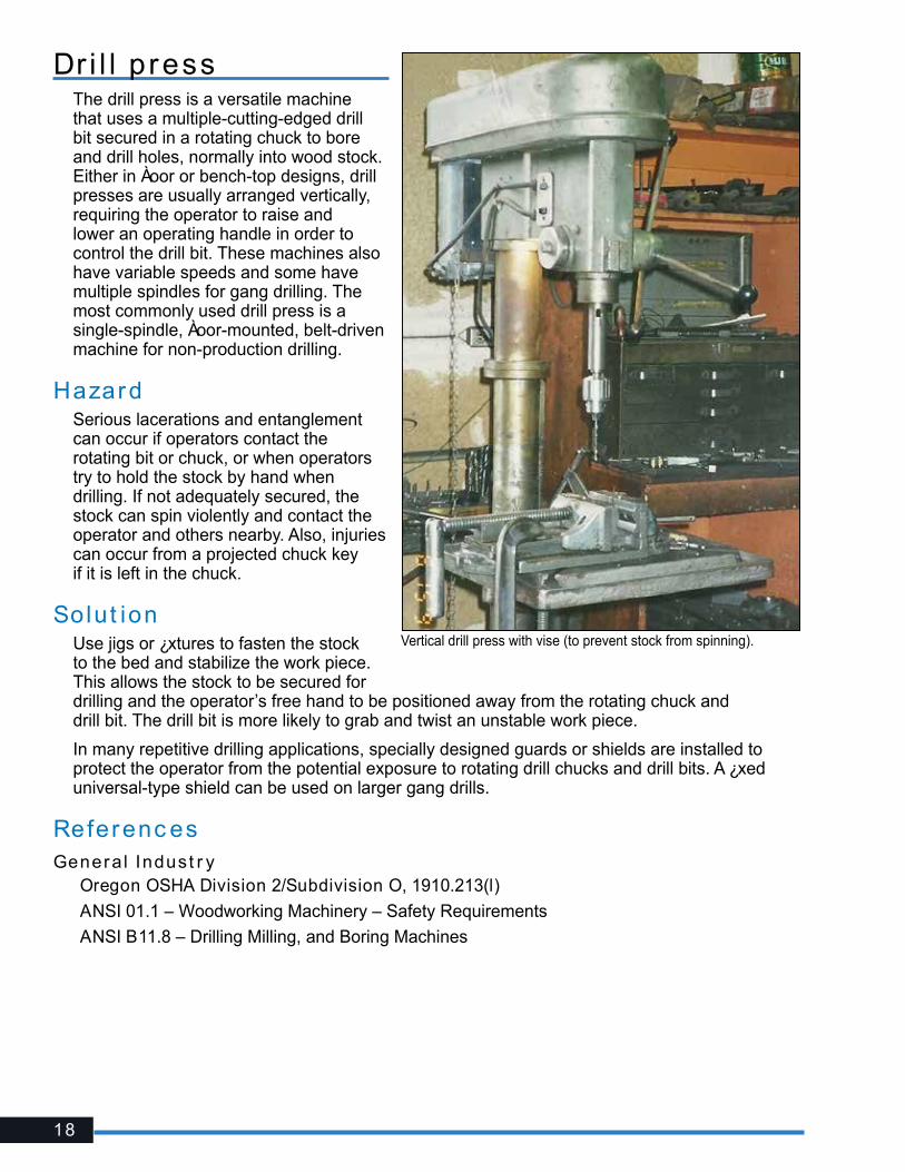
Dr i l l p ress The drill press is a versatile machine that uses a multiple-cutting-edged drill bit secured in a rotating chuck to bore and drill holes, normally into wood stock. Either in Àoor or bench-top designs, drill presses are usually arranged vertically, requiring the operator to raise and lower an operating handle in order to control the drill bit. These machines also have variable speeds and some have multiple spindles for gang drilling. The most commonly used drill press is a single-spindle, Àoor-mounted, belt-driven machine for non-production drilling.
HazardSerious lacerations and entanglement can occur if operators contact the rotating bit or chuck, or when operators try to hold the stock by hand when drilling. If not adequately secured, the stock can spin violently and contact the operator and others nearby. Also, injuries can occur from a projected chuck key if it is left in the chuck.
Solut ionUse jigs or ¿xtures to fasten the stock to the bed and stabilize the work piece. This allows the stock to be secured for drilling and the operator’s free hand to be positioned away from the rotating chuck and drill bit. The drill bit is more likely to grab and twist an unstable work piece.
In many repetitive drilling applications, specially designed guards or shields are installed to protect the operator from the potential exposure to rotating drill chucks and drill bits. A ¿xed universal-type shield can be used on larger gang drills.
Referenc esGeneral Indust r y ��Oregon OSHA Division 2/Subdivision O, 1910.213(l)
��ANSI 01.1 – Woodworking Machinery – Safety Requirements
��ANSI B11.8 – Drilling Milling, and Boring Machines
Vertical drill press with vise (to prevent stock from spinning).
19
I ronw or ker
Scotchman Industries, Inc.
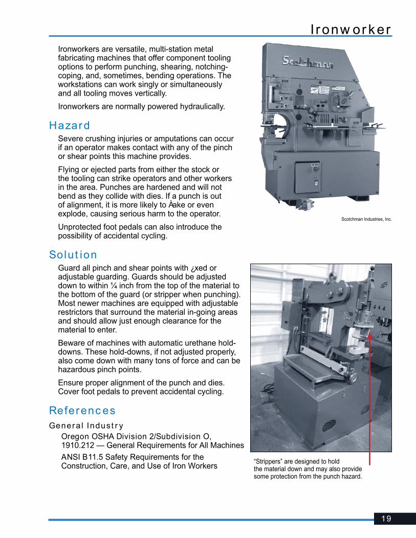
“Strippers” are designed to hold the material down and may also provide some protection from the punch hazard.
Ironworkers are versatile, multi-station metal fabricating machines that offer component tooling options to perform punching, shearing, notching-coping, and, sometimes, bending operations. The workstations can work singly or simultaneously and all tooling moves vertically.
Ironworkers are normally powered hydraulically.
HazardSevere crushing injuries or amputations can occur if an operator makes contact with any of the pinch or shear points this machine provides.
Flying or ejected parts from either the stock or the tooling can strike operators and other workers in the area. Punches are hardened and will not bend as they collide with dies. If a punch is out of alignment, it is more likely to Àake or even explode, causing serious harm to the operator.
Unprotected foot pedals can also introduce the possibility of accidental cycling.
Solut ionGuard all pinch and shear points with ¿xed or adjustable guarding. Guards should be adjusted down to within ¼ inch from the top of the material to the bottom of the guard (or stripper when punching). Most newer machines are equipped with adjustable restrictors that surround the material in-going areas and should allow just enough clearance for the material to enter.
Beware of machines with automatic urethane hold-downs. These hold-downs, if not adjusted properly, also come down with many tons of force and can be hazardous pinch points.
Ensure proper alignment of the punch and dies. Cover foot pedals to prevent accidental cycling.
Referenc esGeneral Indust r y��Oregon OSHA Division 2/Subdivision O,
1910.212 — General Requirements for All Machines
��ANSI B11.5 Safety Requirements for the Construction, Care, and Use of Iron Workers
20
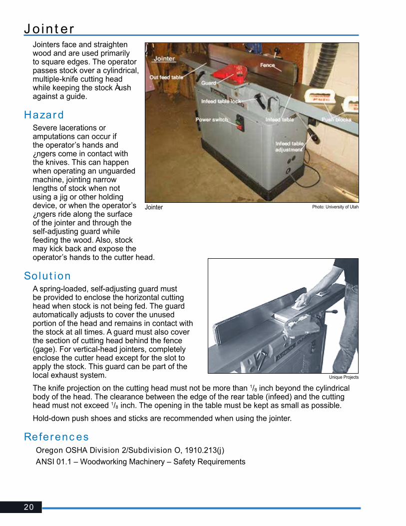
J o in t erJointers face and straighten wood and are used primarily to square edges. The operator passes stock over a cylindrical, multiple-knife cutting head while keeping the stock Àush against a guide.
HazardSevere lacerations or amputations can occur if the operator’s hands and ¿ngers come in contact with the knives. This can happen when operating an unguarded machine, jointing narrow lengths of stock when not using a jig or other holding device, or when the operator’s ¿ngers ride along the surface of the jointer and through the self-adjusting guard while feeding the wood. Also, stock may kick back and expose the operator’s hands to the cutter head.
Solut ionA spring-loaded, self-adjusting guard must be provided to enclose the horizontal cutting head when stock is not being fed. The guard automatically adjusts to cover the unused portion of the head and remains in contact with the stock at all times. A guard must also cover the section of cutting head behind the fence (gage). For vertical-head jointers, completely enclose the cutter head except for the slot to apply the stock. This guard can be part of the local exhaust system.
The knife projection on the cutting head must not be more than 1/8 inch beyond the cylindrical body of the head. The clearance between the edge of the rear table (infeed) and the cutting head must not exceed 1/8 inch. The opening in the table must be kept as small as possible.
Hold-down push shoes and sticks are recommended when using the jointer.
Referenc es� Oregon OSHA Division 2/Subdivision O, 1910.213(j)
� ANSI 01.1 – Woodworking Machinery – Safety Requirements
Unique Projects
Photo: University of UtahJointer

21
Met a l lat heA metal lathe is a precision turning machine that rotates a metal rod or irregular-shaped material while a tool cuts into the material at a preset position. Similar to the wood lathe, the metal lathe normally consists of a headstock and base that houses one or more spindles on which a work-holding device (chuck) can drive the stock and the cutting tools can remove metal, producing mainly cylindrical and conical shapes.
There are basically two main types of metal lathes: Lathes for shaft work (material supported at two or more locations) and lathes for bar (bar stock introduced through the spindle) or chucking work (individual pieces secured at the chuck). Shaft lathes include engine lathes, vertical-shaft lathes, and turning centers. Bar and chucking lathes include turret lathes (vertical and horizontal) and vertical boring mills.
HazardSevere injuries and death can occur primarily from being caught in or struck by rotating parts. An operator can be pulled into the lathe from working perilously close (e.g., polishing a slotted shaft with emery cloth) or wearing gloves, loose clothing, loose hair, jewelry, etc. Trapping spaces are also created between the cutting tool, its mounting, and the work piece or chuck.
Projected parts or material such as chuck keys or unsecured work pieces can also strike nearby operators.
Flying chips and coolant also present hazards to the operator.
Solut ionAvoid wearing gloves, loose clothing, long hair, jewelry, or other dangling objects near lathe operations. Pay close attention to work pieces that have keyway slots or other surface pro¿les that may increase the risk of entanglement. Assess the need to manually polish (e.g., emery cloth) rotating material. If necessary, consider milling keyways or other pro¿les after polishing or use emery cloth with the aid of a tool or backing boards. Always use a brush or tool to remove chips.
Cover work-holding devices (chucks) and tool trapping space hazards (especially in automatic or semiautomatic modes) with secured ¿xed or movable guards or shields. Vertical lathes and controlled turning centers are normally provided with ¿xed or interlocked guarding that prevents access during the automatic cycle.
RDM Industrial Services Ltd.
Hazardous exposures are present simply due to the operator’s close proximity to the lathe’s rotating parts.
Fabricated quill-mounted guard to enclose cathead.
22
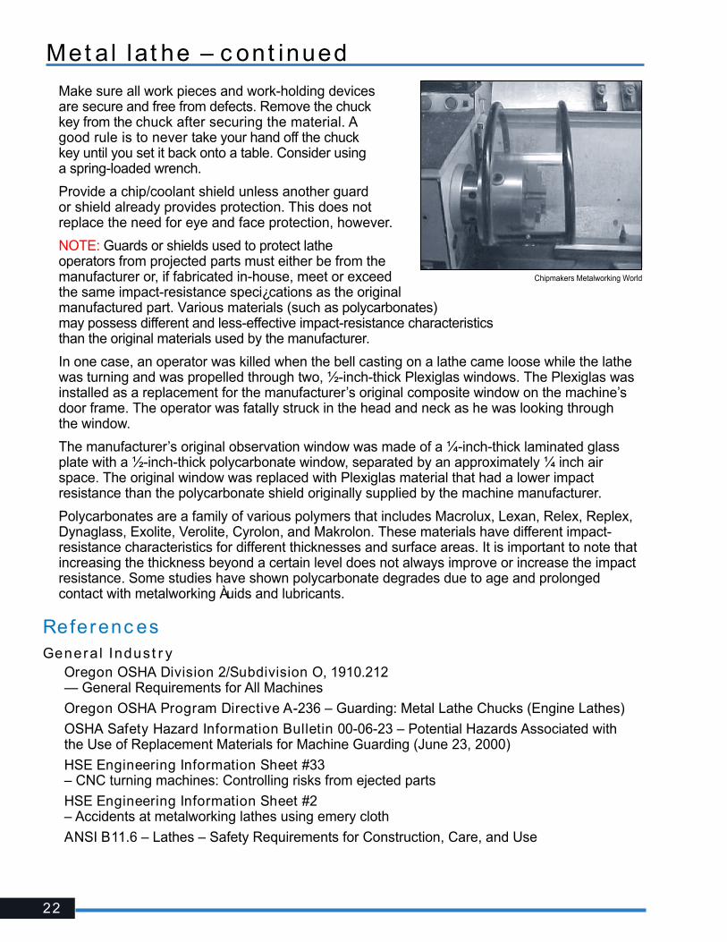
Make sure all work pieces and work-holding devices are secure and free from defects. Remove the chuck key from the chuck after securing the material. A good rule is to never take your hand off the chuck key until you set it back onto a table. Consider using a spring-loaded wrench.
Provide a chip/coolant shield unless another guard or shield already provides protection. This does not replace the need for eye and face protection, however.
NOTE: Guards or shields used to protect lathe operators from projected parts must either be from the manufacturer or, if fabricated in-house, meet or exceed the same impact-resistance speci¿cations as the original manufactured part. Various materials (such as polycarbonates) may possess different and less-effective impact-resistance characteristics than the original materials used by the manufacturer.
In one case, an operator was killed when the bell casting on a lathe came loose while the lathe was turning and was propelled through two, ½-inch-thick Plexiglas windows. The Plexiglas was installed as a replacement for the manufacturer’s original composite window on the machine’s door frame. The operator was fatally struck in the head and neck as he was looking through the window.
The manufacturer’s original observation window was made of a ¼-inch-thick laminated glass plate with a ½-inch-thick polycarbonate window, separated by an approximately ¼ inch air space. The original window was replaced with Plexiglas material that had a lower impact resistance than the polycarbonate shield originally supplied by the machine manufacturer.
Polycarbonates are a family of various polymers that includes Macrolux, Lexan, Relex, Replex, Dynaglass, Exolite, Verolite, Cyrolon, and Makrolon. These materials have different impact-resistance characteristics for different thicknesses and surface areas. It is important to note that increasing the thickness beyond a certain level does not always improve or increase the impact resistance. Some studies have shown polycarbonate degrades due to age and prolonged contact with metalworking Àuids and lubricants.
Referenc esGeneral Indust r y��Oregon OSHA Division 2/Subdivision O, 1910.212
— General Requirements for All Machines
��Oregon OSHA Program Directive A-236 – Guarding: Metal Lathe Chucks (Engine Lathes)
��OSHA Safety Hazard Information Bulletin 00-06-23 – Potential Hazards Associated with the Use of Replacement Materials for Machine Guarding (June 23, 2000)
��HSE Engineering Information Sheet #33 – CNC turning machines: Controlling risks from ejected parts
��HSE Engineering Information Sheet #2 – Accidents at metalworking lathes using emery cloth
��ANSI B11.6 – Lathes – Safety Requirements for Construction, Care, and Use
Chipmakers Metalworking World
Met a l lat he – c ont inued
23
Wood lat he
Delta Inc.
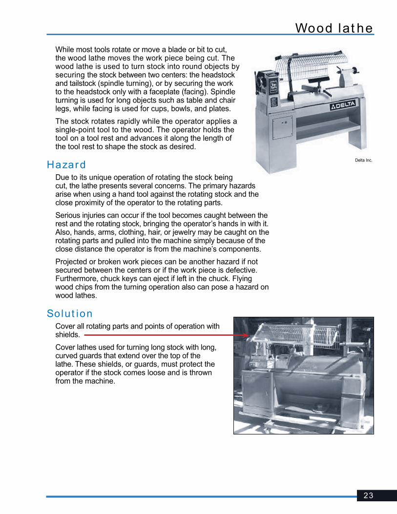
While most tools rotate or move a blade or bit to cut, the wood lathe moves the work piece being cut. The wood lathe is used to turn stock into round objects by securing the stock between two centers: the headstock and tailstock (spindle turning), or by securing the work to the headstock only with a faceplate (facing). Spindle turning is used for long objects such as table and chair legs, while facing is used for cups, bowls, and plates.
The stock rotates rapidly while the operator applies a single-point tool to the wood. The operator holds the tool on a tool rest and advances it along the length of the tool rest to shape the stock as desired.
HazardDue to its unique operation of rotating the stock being cut, the lathe presents several concerns. The primary hazards arise when using a hand tool against the rotating stock and the close proximity of the operator to the rotating parts.
Serious injuries can occur if the tool becomes caught between the rest and the rotating stock, bringing the operator’s hands in with it. Also, hands, arms, clothing, hair, or jewelry may be caught on the rotating parts and pulled into the machine simply because of the close distance the operator is from the machine’s components.
Projected or broken work pieces can be another hazard if not secured between the centers or if the work piece is defective. Furthermore, chuck keys can eject if left in the chuck. Flying wood chips from the turning operation also can pose a hazard on wood lathes.
Solut ionCover all rotating parts and points of operation with shields.
Cover lathes used for turning long stock with long, curved guards that extend over the top of the lathe. These shields, or guards, must protect the operator if the stock comes loose and is thrown from the machine.
24
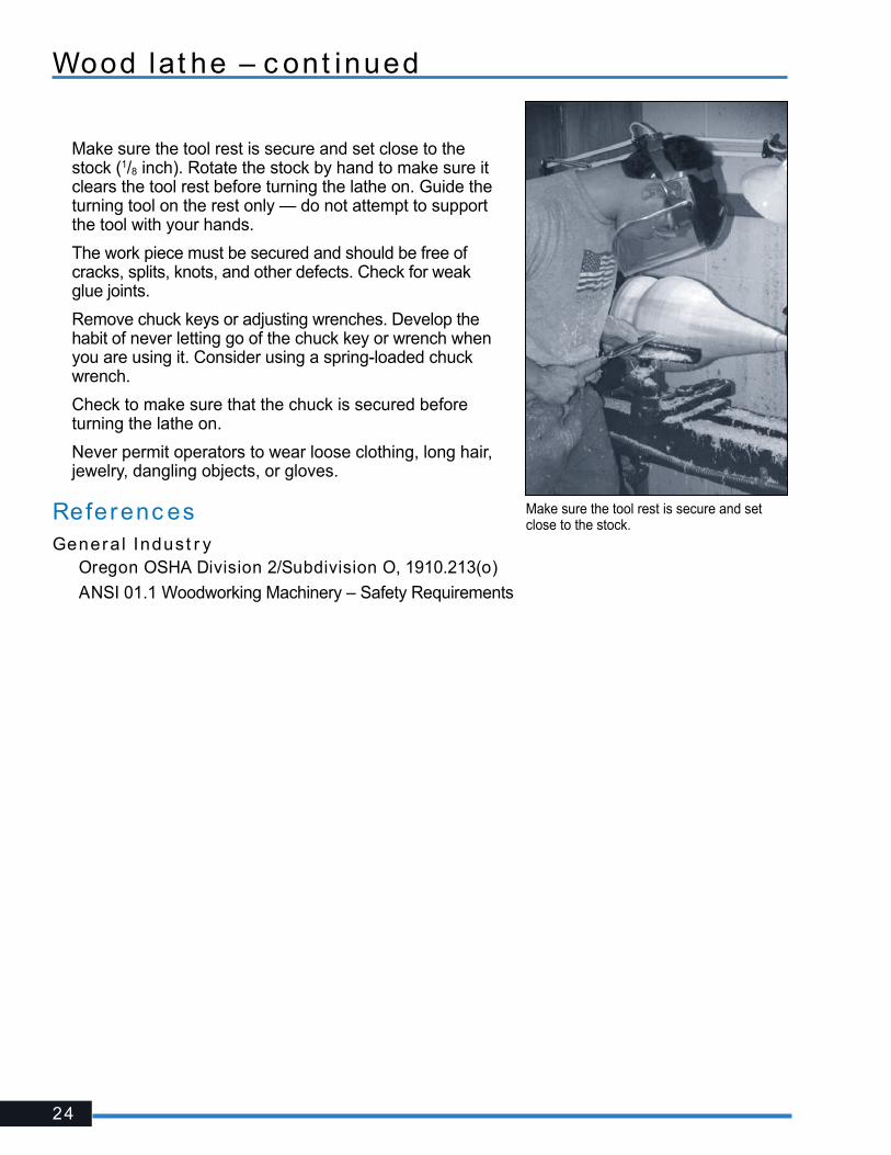
Make sure the tool rest is secure and set close to the stock (1/8 inch). Rotate the stock by hand to make sure it clears the tool rest before turning the lathe on. Guide the turning tool on the rest only — do not attempt to support the tool with your hands.
The work piece must be secured and should be free of cracks, splits, knots, and other defects. Check for weak glue joints.
Remove chuck keys or adjusting wrenches. Develop the habit of never letting go of the chuck key or wrench when you are using it. Consider using a spring-loaded chuck wrench.
Check to make sure that the chuck is secured before turning the lathe on.
Never permit operators to wear loose clothing, long hair, jewelry, dangling objects, or gloves.
Referenc esGeneral Indust r y��Oregon OSHA Division 2/Subdivision O, 1910.213(o)
��ANSI 01.1 Woodworking Machinery – Safety Requirements
Make sure the tool rest is secure and set close to the stock.
Wood lat he – c ont inued
25
Mi l l ing m ac hineA milling machine removes material from a work piece by rotating a cutting tool (cutter) and moving it into the work piece. Milling machines, either vertical or horizontal, are usually used to machine Àat and irregularly shaped surfaces and can be used to drill, bore, and cut gears, threads, and slots.
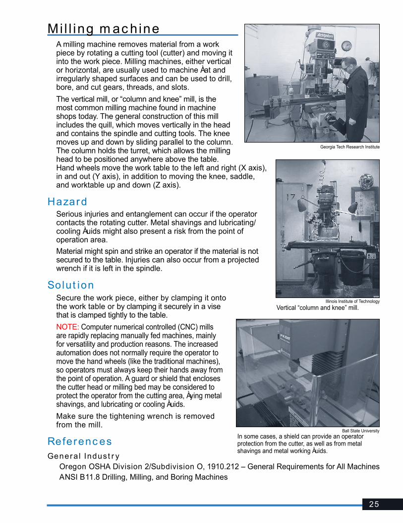
The vertical mill, or “column and knee” mill, is the most common milling machine found in machine shops today. The general construction of this mill includes the quill, which moves vertically in the head and contains the spindle and cutting tools. The knee moves up and down by sliding parallel to the column. The column holds the turret, which allows the milling head to be positioned anywhere above the table. Hand wheels move the work table to the left and right (X axis), in and out (Y axis), in addition to moving the knee, saddle, and worktable up and down (Z axis).
HazardSerious injuries and entanglement can occur if the operator contacts the rotating cutter. Metal shavings and lubricating/cooling Àuids might also present a risk from the point of operation area.
Material might spin and strike an operator if the material is not secured to the table. Injuries can also occur from a projected wrench if it is left in the spindle.
Solut ionSecure the work piece, either by clamping it onto the work table or by clamping it securely in a vise that is clamped tightly to the table.
NOTE: Computer numerical controlled (CNC) mills are rapidly replacing manually fed machines, mainly for versatility and production reasons. The increased automation does not normally require the operator to move the hand wheels (like the traditional machines), so operators must always keep their hands away from the point of operation. A guard or shield that encloses the cutter head or milling bed may be considered to protect the operator from the cutting area, Àying metal shavings, and lubricating or cooling Àuids.
Make sure the tightening wrench is removed from the mill.
Referenc esGeneral Indust r y� Oregon OSHA Division 2/Subdivision O, 1910.212 – General Requirements for All Machines� ANSI B11.8 Drilling, Milling, and Boring Machines
Ball State UniversityIn some cases, a shield can provide an operator protection from the cutter, as well as from metal shavings and metal working Àuids.
Vertical “column and knee” mill.Illinois Institute of Technology
Georgia Tech Research Institute
26
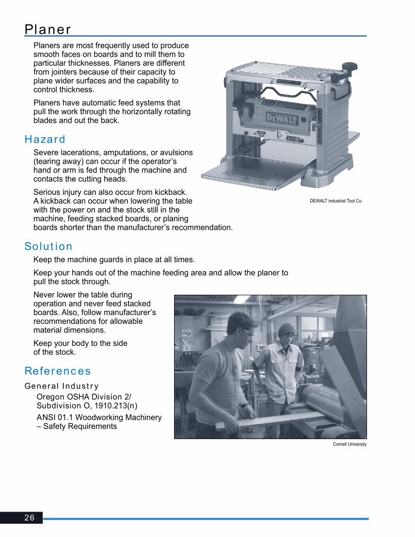
PlanerPlaners are most frequently used to produce smooth faces on boards and to mill them to particular thicknesses. Planers are different from jointers because of their capacity to plane wider surfaces and the capability to control thickness.
Planers have automatic feed systems that pull the work through the horizontally rotating blades and out the back.
HazardSevere lacerations, amputations, or avulsions (tearing away) can occur if the operator’s hand or arm is fed through the machine and contacts the cutting heads.
Serious injury can also occur from kickback. A kickback can occur when lowering the table with the power on and the stock still in the machine, feeding stacked boards, or planing boards shorter than the manufacturer’s recommendation.
Solut ionKeep the machine guards in place at all times.
Keep your hands out of the machine feeding area and allow the planer to pull the stock through.
Never lower the table during operation and never feed stacked boards. Also, follow manufacturer’s recommendations for allowable material dimensions.
Keep your body to the side of the stock.
Referenc esGeneral Indust r y� Oregon OSHA Division 2/
Subdivision O, 1910.213(n)
� ANSI 01.1 Woodworking Machinery – Safety Requirements
Cornell University
DEWALT industrial Tool Co.
27
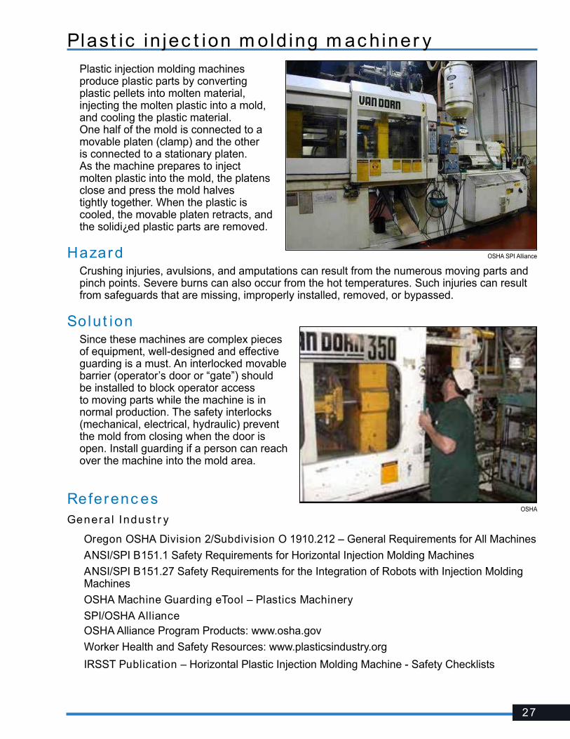
Plast ic in jec t ion m old ing m ac hiner yPlastic injection molding machines produce plastic parts by converting plastic pellets into molten material, injecting the molten plastic into a mold, and cooling the plastic material. One half of the mold is connected to a movable platen (clamp) and the other is connected to a stationary platen. As the machine prepares to inject molten plastic into the mold, the platens close and press the mold halves tightly together. When the plastic is cooled, the movable platen retracts, and the solidi¿ed plastic parts are removed.
HazardCrushing injuries, avulsions, and amputations can result from the numerous moving parts and pinch points. Severe burns can also occur from the hot temperatures. Such injuries can result from safeguards that are missing, improperly installed, removed, or bypassed.
Solut ionSince these machines are complex pieces of equipment, well-designed and effective guarding is a must. An interlocked movable barrier (operator’s door or “gate”) should be installed to block operator access to moving parts while the machine is in normal production. The safety interlocks (mechanical, electrical, hydraulic) prevent the mold from closing when the door is open. Install guarding if a person can reach over the machine into the mold area.
Referenc esGeneral Indust r y
� Oregon OSHA Division 2/Subdivision O 1910.212 – General Requirements for All Machines
� ANSI/SPI B151.1 Safety Requirements for Horizontal Injection Molding Machines
� ANSI/SPI B151.27 Safety Requirements for the Integration of Robots with Injection Molding Machines
� OSHA Machine Guarding eTool – Plastics Machinery
� SPI/OSHA AllianceOSHA Alliance Program Products: www.osha.gov
Worker Health and Safety Resources: www.plasticsindustry.org
� IRSST Publication – Horizontal Plastic Injection Molding Machine - Safety Checklists
OSHA SPI Alliance
OSHA
28
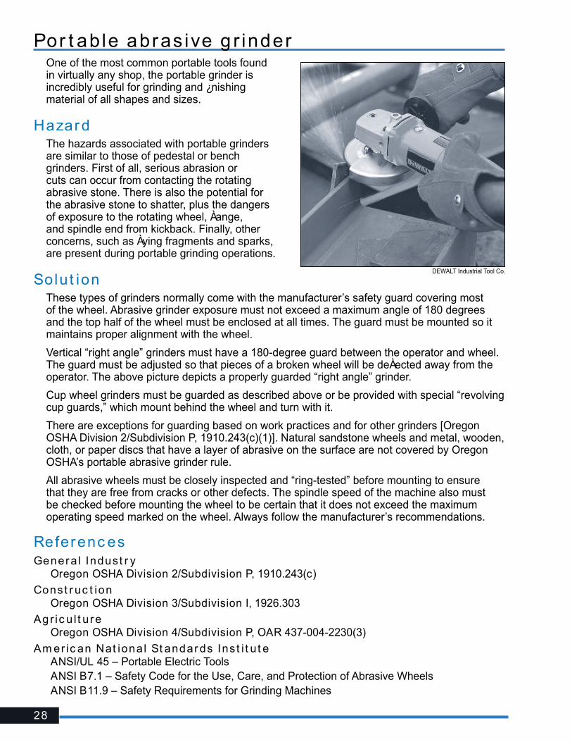
Por t ab le abras ive g r inderOne of the most common portable tools found in virtually any shop, the portable grinder is incredibly useful for grinding and ¿nishing material of all shapes and sizes.
HazardThe hazards associated with portable grinders are similar to those of pedestal or bench grinders. First of all, serious abrasion or cuts can occur from contacting the rotating abrasive stone. There is also the potential for the abrasive stone to shatter, plus the dangers of exposure to the rotating wheel, Àange, and spindle end from kickback. Finally, other concerns, such as Àying fragments and sparks, are present during portable grinding operations.
Solut ionThese types of grinders normally come with the manufacturer’s safety guard covering most of the wheel. Abrasive grinder exposure must not exceed a maximum angle of 180 degrees and the top half of the wheel must be enclosed at all times. The guard must be mounted so it maintains proper alignment with the wheel.
Vertical “right angle” grinders must have a 180-degree guard between the operator and wheel. The guard must be adjusted so that pieces of a broken wheel will be deÀected away from the operator. The above picture depicts a properly guarded “right angle” grinder.
Cup wheel grinders must be guarded as described above or be provided with special “revolving cup guards,” which mount behind the wheel and turn with it.
There are exceptions for guarding based on work practices and for other grinders [Oregon OSHA Division 2/Subdivision P, 1910.243(c)(1)]. Natural sandstone wheels and metal, wooden, cloth, or paper discs that have a layer of abrasive on the surface are not covered by Oregon OSHA’s portable abrasive grinder rule.
All abrasive wheels must be closely inspected and “ring-tested” before mounting to ensure that they are free from cracks or other defects. The spindle speed of the machine also must be checked before mounting the wheel to be certain that it does not exceed the maximum operating speed marked on the wheel. Always follow the manufacturer’s recommendations.
Referenc esGeneral Indust r y� Oregon OSHA Division 2/Subdivision P, 1910.243(c)
Const r uc t ion � Oregon OSHA Division 3/Subdivision I, 1926.303
Agr ic u l t ure � Oregon OSHA Division 4/Subdivision P, OAR 437-004-2230(3)
Am er ic an Nat ional St andards Inst i t u t e� ANSI/UL 45 – Portable Electric Tools� ANSI B7.1 – Safety Code for the Use, Care, and Protection of Abrasive Wheels� ANSI B11.9 – Safety Requirements for Grinding Machines
DEWALT Industrial Tool Co.

29
Por t ab le be l t sanderThe portable belt sander is a general-purpose ¿nishing tool. The belt is looped around two or more pulleys. The belt sander’s linear motion makes it an excellent tool for sanding with the grain of the wood.
HazardSerious abrasion can occur from contacting the moving belt.
In-running nip points – created where the belt meets the pulley – can be present on the side of the tool. Nip points allow ¿ngers, clothing, or hair to become caught in the tool.
Solut ionBoth hands should be used to operate the portable belt sander, one on the trigger switch and the other on the front handle.
Guard the unused runs of the sanding belt and all in-running nip points. This is normally accomplished by the tool’s casing, enclosing the top portion of the belt and much of the side. The enclosure, or guard, on the sides must prevent the operator from contacting the nip points.
Referenc esGeneral Indust r y� Oregon OSHA Division 2/Subdivision P,
1910.243(a)(3)
Agr ic u l t ure � Oregon OSHA Division 4/Subdivision P,
OAR 437-004-2230(1)(d)
DEWALT Industrial Tool Co.

30
Por t ab le c i r c u lar sawThe portable circular saw is probably the most commonly used power saw. Circular saws are versatile and used to crosscut, rip, and bevel cut.
The operator adjusts the saw to the proper cutting depth and pushes the tool through the wood.
HazardSevere cuts and amputations can occur if the operator contacts the saw blade. Many injuries occur when the lower portion of the blade is fully exposed during operation or when the operator places his or her hand under the base plate (shoe) of the saw.
Kickbacks can also present a signi¿cant hazard. They occur when the saw blade binds in the cut and the saw kicks back toward the operator. Binding most often occurs when the piece being cut off is not allowed to fall down, if cutting on an incline, or between two saw horses and either the weight of the saw or the forward motion causes the saw kerf (line of cut) to close.
Solut ionAll saws with a blade diameter greater than two inches must be equipped with guards above and below the base plate (shoe). The upper guard must cover the saw to the depth of the teeth, except for the minimum arc required to permit the base to be tilted for bevel cuts. The lower guard must enclose the teeth as much as possible and cover the unused portion of the blade when cutting.
When the tool is withdrawn from the work, the lower guard must automatically and instantly return to the covering position. Check that the retracting lower guard has returned to its starting position before laying down the saw. If the saw is set down with the guard open, it usually spins in a tight circle – sometimes cutting its own cord or possibly contacting the worker’s foot.
In addition, the lower guard must be equipped with a lug or lever, located safely away from the blade teeth, that will permit the operator to shift the guard safely for starting unusual cuts. Never hold or force the retracting lower guard in the open position and never pin the guard up.
DEWALT Industrial Tool Co.
Never pin back the blade guard.

31
Kickbacks can be minimized by setting the proper blade depth so that the lowest tooth extends no more than 1/8 inch beyond the bottom of the material. This limits the area of the blade in the kerf and also exposes less of the blade if the saw does kick back.
It’s also important to keep the saw kerf open, reducing the chance for the saw to bind. The board being cut should be positioned so that the weight of the cutoff keeps the saw kerf open as the cut is being made. Also, make sure you are not cutting uphill – even the slightest incline can cause the saw to bind. The saw must always move in a straight line. If the blade wanders from its straight path, the rear of the blade can bind against the side of the kerf. If the saw has to be turned off in the middle of a cut, make sure the blade has stopped spinning before taking your hand off the saw. Always keep your body out of the line of potential kickback.
Use two hands whenever possible, one on the trigger switch and the other on a front knob handle.
Secure work being cut to avoid movement.
Referenc esGeneral Indust r y� Oregon OSHA Division 2/Subdivision P, 1910.243(a)(1)(i)
� Oregon OSHA Division 2/Subdivision P, OAR 437-002-0266(1)
Const r uc t ion� Oregon OSHA Division 3/Subdivision I, 1926.304(d)
Agr ic u l t ure� Oregon OSHA Division 4/Subdivision P, OAR 437-004-2230(1)(a)
Am er ic an Nat ional St andards Inst i t u t e� ANSI/UL 45 – Portable Electric Tools

32
Por t ab le j igsawHandheld jigsaws are useful for cutting intricate curves and patterns in thin stock. They have thin blades that move rapidly up and down through the saw’s guide plate. The blade is held in a chuck. The operator either holds the saw with one hand while the other hand is used to secure the stock, or the saw is held with both hands if the stock is already secured.
HazardSerious cuts can occur when the operator contacts the reciprocating blade. Much of the blade is exposed by design and contact can be made before or after the cut, or during the cut if the operator’s hand is securing the material underneath the stock and in the path of the blade.
Solut ionEnsure the portion of the blade above the guide plate is adequately guarded. This may require setting it to an appropriate height.
Be aware of the portion of the blade below the stock, especially if you are using one hand to secure the material.
Make turns slowly and use a narrow blade for sharp turns.
Referenc esGeneral Indust r y� Oregon OSHA Division 2/Subdivision P,
1910.243
� ANSI/UL 45 – Portable Electric Tools
Const r uc t ion� Oregon OSHA Division 3/Subdivision I, 1926.300
Agr ic u l t ure� Oregon OSHA Division 4/Subdivision P, 437-004-2230
DEWALT Industrial Tool Co.
33
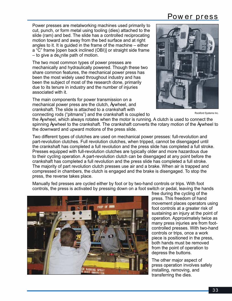
Pow er pressPower presses are metalworking machines used primarily to cut, punch, or form metal using tooling (dies) attached to the slide (ram) and bed. The slide has a controlled reciprocating motion toward and away from the bed surface and at right angles to it. It is guided in the frame of the machine – either a “C” frame [open back inclined (OBI)] or straight side frame – to give a de¿nite path of motion.
The two most common types of power presses are mechanically and hydraulically powered. Though these two share common features, the mechanical power press has been the most widely used throughout industry and has been the subject of most of the research done, primarily due to its tenure in industry and the number of injuries associated with it.
The main components for power transmission on a mechanical power press are the clutch, Àywheel, and crankshaft. The slide is attached to a crankshaft with connecting rods (“pitmans”) and the crankshaft is coupled to the Àywheel, which always rotates when the motor is running. A clutch is used to connect the spinning Àywheel to the crankshaft. The crankshaft converts the rotary motion of the Àywheel to the downward and upward motions of the press slide.
Two different types of clutches are used on mechanical power presses: full-revolution and part-revolution clutches. Full revolution clutches, when tripped, cannot be disengaged until the crankshaft has completed a full revolution and the press slide has completed a full stroke. Presses equipped with full-revolution clutches are typically older and more hazardous due to their cycling operation. A part-revolution clutch can be disengaged at any point before the crankshaft has completed a full revolution and the press slide has completed a full stroke. The majority of part revolution clutch presses use air and a brake. When air is trapped and compressed in chambers, the clutch is engaged and the brake is disengaged. To stop the press, the reverse takes place.
Manually fed presses are cycled either by foot or by two-hand controls or trips. With foot controls, the press is activated by pressing down on a foot switch or pedal, leaving the hands
free during the cycling of the press. This freedom of hand movement places operators using foot controls at a greater risk of sustaining an injury at the point of operation. Approximately twice as many press injuries are from foot-controlled presses. With two-hand controls or trips, once a work piece is positioned in the press, both hands must be removed from the point of operation to depress the buttons.
The other major aspect of press operation involves safely installing, removing, and transferring the dies.
Rockford Systems Inc.

34
HazardA machine that punches metal in a blink of an eye leaves little to the imagination as to what it can do to body parts. Severe crushing injuries, amputations, and even death can occur in the point of operation or while performing servicing tasks such as die setting or troubleshooting.
According to Federal Bureau of Labor and Statistics, approximately 7,000 amputations occur each year and many are from mechanical and hydraulic presses.
Flying or ejected parts from either the stock or the dies can also strike operators and other workers in the operation area.
Unprotected operating controls, especially foot pedals, also can introduce the possibility of accidental cycling.
Solut ionThe point of operation of all power presses must be safeguarded. Safeguarding is accomplished either by barrier guarding or the use of devices. Barrier guarding prevents entry into the die area by physically enclosing the point of operation. Devices control entry by allowing the operator to reach into the die area to feed or remove parts and will either prevent a machine cycle, stop the hazardous down-stroke, or pull the operator’s hands out if his or her hands are detected or remain in the point of operation. Guarding is not required if the point of operation opening is ¼ inch or less.
Safeguarding choices for mechanical power presses depend on the clutch systems. Feasible methods for full-revolution presses include ¿xed or adjustable barrier guarding, two-hand trips, pullbacks, restraints, or type “A” gates. Part-revolution presses are usually equipped with barrier guarding, presence-sensing devices, two-hand controls or trips, type “A” or “B” gates, pullbacks, or restraints. The safeguarding options for a part-revolution press also can be installed on hydraulic presses.
Fixed, interlocked, or adjustable barrier guarding is best for applications where the operator does not need frequent access to the point of operation, for example, on a mechanical power press in continuous mode. An advantage to using barrier guarding is that it presents a physical barrier between people (the operator and other workers) and the machine’s pinch point, in addition to capturing any Àying parts from either the stock or the die.
Barrier guarding must be designed and constructed so that people cannot reach over, under, around, or through the guard and reach the pinch-point hazard. If there are openings in the barrier guard, the openings must be in compliance with the OSHA (or ANSI) guard-opening requirements. The following are the maximum permissible openings as listed in Table O-10 of OSHA’s Mechanical Power Press Standard.
Pow er press – c ont inued
Rockford Systems Inc.
Barrier guarding on an OBI mechanical power press.
35
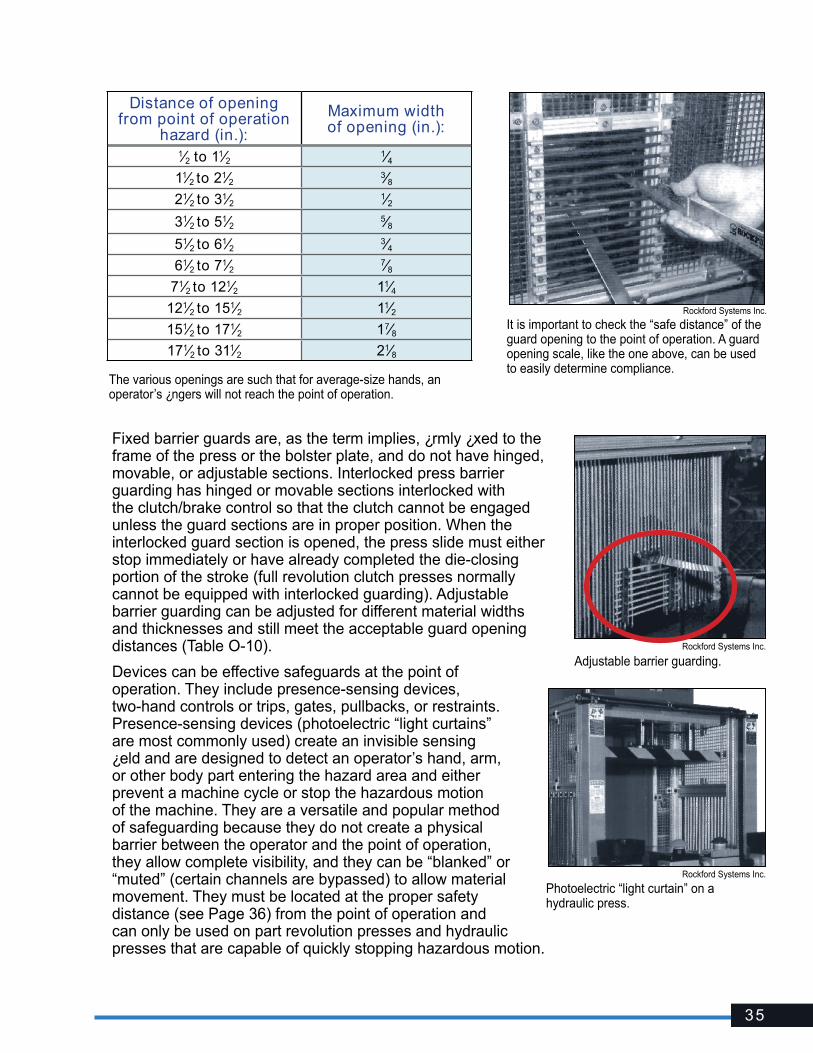
Fixed barrier guards are, as the term implies, ¿rmly ¿xed to the frame of the press or the bolster plate, and do not have hinged, movable, or adjustable sections. Interlocked press barrier guarding has hinged or movable sections interlocked with the clutch/brake control so that the clutch cannot be engaged unless the guard sections are in proper position. When the interlocked guard section is opened, the press slide must either stop immediately or have already completed the die-closing portion of the stroke (full revolution clutch presses normally cannot be equipped with interlocked guarding). Adjustable barrier guarding can be adjusted for different material widths and thicknesses and still meet the acceptable guard opening distances (Table O-10).
Devices can be effective safeguards at the point of operation. They include presence-sensing devices, two-hand controls or trips, gates, pullbacks, or restraints. Presence-sensing devices (photoelectric “light curtains” are most commonly used) create an invisible sensing ¿eld and are designed to detect an operator’s hand, arm, or other body part entering the hazard area and either prevent a machine cycle or stop the hazardous motion of the machine. They are a versatile and popular method of safeguarding because they do not create a physical barrier between the operator and the point of operation, they allow complete visibility, and they can be “blanked” or “muted” (certain channels are bypassed) to allow material movement. They must be located at the proper safety distance (see Page 36) from the point of operation and can only be used on part revolution presses and hydraulic presses that are capable of quickly stopping hazardous motion.
It is important to check the “safe distance” of the guard opening to the point of operation. A guard opening scale, like the one above, can be used to easily determine compliance.
Rockford Systems Inc.
Adjustable barrier guarding.
Rockford Systems Inc.
Rockford Systems Inc.
Photoelectric “light curtain” on a hydraulic press.
Distance of opening from point of operation
hazard (in.):
Maximum width of opening (in.):
1⁄2 to 11⁄2 1⁄411⁄2 to 21⁄2 3⁄821⁄2 to 31⁄2 1⁄231⁄2 to 51⁄2 5⁄851⁄2 to 61⁄2 3⁄461⁄2 to 71⁄2 7⁄8
71⁄2 to 121⁄2 11⁄4121⁄2 to 151⁄2 11⁄2151⁄2 to 171⁄2 17⁄8171⁄2 to 311⁄2 21⁄8
The various openings are such that for average-size hands, an operator’s ¿ngers will not reach the point of operation.

36
Two-hand controls are also used on part-revolution or hydraulic presses and require the use of both of the operator’s hands to concurrently depress two individual palm buttons to cycle the machine. These controls must also require the operator to hold them down through the die-closing portion of the stroke (downstroke). Two-hand trips are similar to two-hand controls, but are usually equipped on full-revolution presses. Trips require only momentary actuation of the palm buttons, and once the buttons have been actuated, they can be released quickly and the machine will make one full cycle or stroke. Of course, locating two-hand controls or trips at their proper safety distances (see below) are critical for operator safety. Also, they must incorporate both anti-tiedown and anti-repeat features. Anti-tiedown prevents “tying” one button down and still being able to cycle the machine by depressing the other. Anti-repeat prevents continuous cycling. If more than one operator is operating a press, each operator must have their own set of controls/trips.
Safety distance, as applied to press safeguarding using presence-sensing devices, two-hand controls, two-hand trips, and interlocked barrier guards, is a calculation to determine where these devices must be located from the point-of-operation hazard so that hazardous motion is effectively stopped or prevented before contact can be made. Safety distance is calculated with an equation using the maximum speed that someone can approach the hazard (63 inches/second) and the total time it takes to stop hazardous motion (seconds). Additional factors such as, but not limited to, depth penetration (presence sensing) and reaction times of the control system and safeguard interface are also included. Stopping time is normally measured using the brake monitor or a portable stop-time measurement device. The ANSI formula takes more factors into account and normally results in a larger safety distance.
Gates are movable barriers that enclose (in combination with barrier guards) the point of operation before the machine cycle can be started, and remain closed until the downstroke has completed. There are two types: Type “A” gate remains closed during the entire cycle and type “B” gate remains closed during the downstroke only. Gates are normally constructed of clear polycarbonate and powered by air and gravity.
Pullback devices use a series of cables attached to the operator’s hands or wrists. Slack is taken up during the downstroke cycle, pulling the operator’s hands from the point of operation, if they are still there. Restraint (holdout) devices are also attached to the operator using cables or straps, but must be anchored and adjusted so the operator’s hands can never reach into the point of operation.
Pow er press – c ont inued
Rockford Systems Inc.Type “A” gate.
Rockford Systems Inc.
Two-hand controls on a part revolution press.
Press restraints.

37
There is no retracting action involved. Consequently, hand-feeding tools are often necessary if the operation involves placing small material into the dies.
It’s important to remember that most devices do not provide protection from Àying parts. Also, control reliability (see Glossary) and a brake monitor (see Glossary) must be incorporated in part revolution mechanical power presses using a presence sensing device, two-hand control, type “B” gate, or interlocked barrier guarding.
Full-revolution mechanical power presses must incorporate a single-stroke (or anti-repeat) feature that allows the clutch to engage and the press to cycle only once each time the foot control or two-hand trips are depressed.
To prevent accidental cycling, effectively cover or guard all hand and foot controls. Foot pedals must be attached to a nonslip surface to prevent the pedal from sliding.
Hand tools can be used for placing and removing material, but they do not replace guarding.
Appropriate die-setting procedures must be established and followed to ensure the safe design, handling, installation, and removal of the dies. Safety blocks must be used and enforced. Weekly inspections and regular maintenance of presses, parts, auxiliary equipment, and safeguards must be followed and documented.
If the back of the press presents a hazard to others, prevent access with a barricade.
Noti¿cation of mechanical power press injury:
All point-of-operation injuries associated with a mechanical power press must be reported to Oregon OSHA within 30 days of occurrence. Information such as the type of press, task performed, type of safeguards, cause of injury, and feeding method must be provided.
Referenc esGeneral Indust r y� Oregon OSHA Division 2/Subdivision O, 1910.217 – Mechanical Power Presses
� Oregon OSHA Division 2/Subdivision O, 1910.212 – General Requirements for All Machines
� ANSI B11.1 Safety Requirements for Mechanical Power Presses
� ANSI B11.19 Safeguarding When Referenced by the Other B11 Machine Tool Safety Standards — Performance Criteria for the Design, Construction, care, and Operation
� NIOSH Publication No. 87-107 “Injuries and Amputations Resulting From Work With Mechanical Power Presses” (May 22, 1987)
� Oregon OSHA Program Directive A-291 – Machine Guarding: Mechanical Power Presses
38
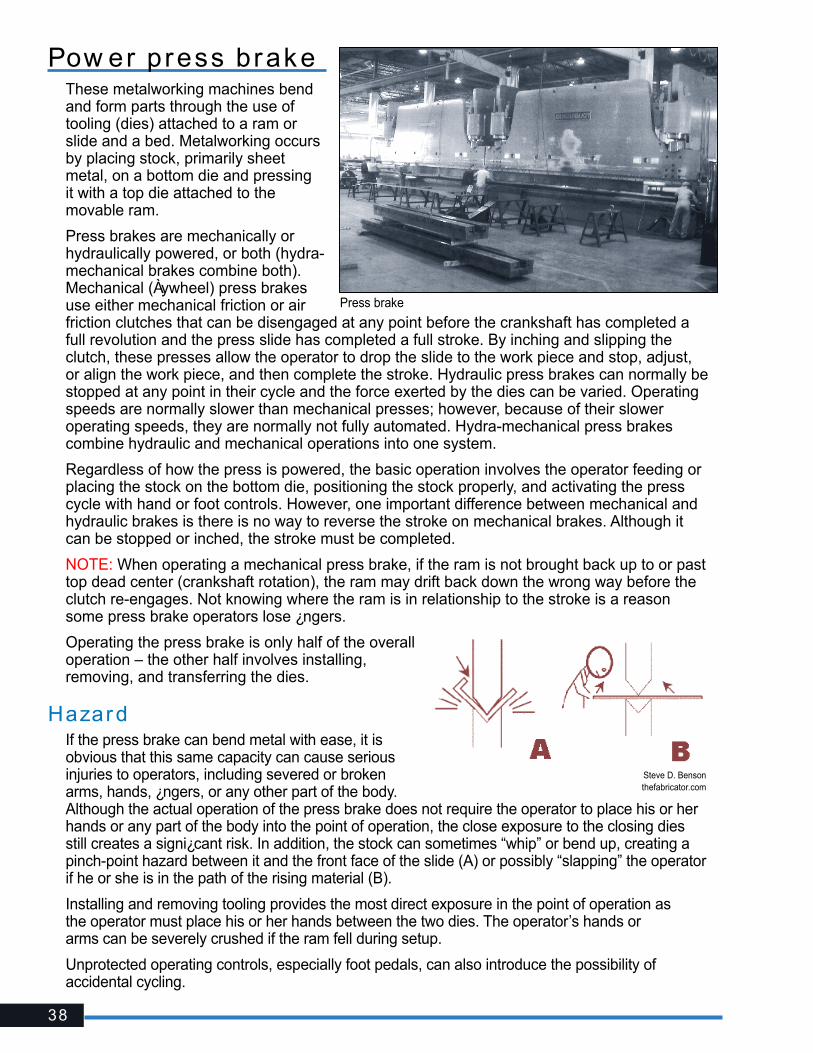
Pow er press brakeThese metalworking machines bend and form parts through the use of tooling (dies) attached to a ram or slide and a bed. Metalworking occurs by placing stock, primarily sheet metal, on a bottom die and pressing it with a top die attached to the movable ram.
Press brakes are mechanically or hydraulically powered, or both (hydra-mechanical brakes combine both). Mechanical (Àywheel) press brakes use either mechanical friction or air friction clutches that can be disengaged at any point before the crankshaft has completed a full revolution and the press slide has completed a full stroke. By inching and slipping the clutch, these presses allow the operator to drop the slide to the work piece and stop, adjust, or align the work piece, and then complete the stroke. Hydraulic press brakes can normally be stopped at any point in their cycle and the force exerted by the dies can be varied. Operating speeds are normally slower than mechanical presses; however, because of their slower operating speeds, they are normally not fully automated. Hydra-mechanical press brakes combine hydraulic and mechanical operations into one system.
Regardless of how the press is powered, the basic operation involves the operator feeding or placing the stock on the bottom die, positioning the stock properly, and activating the press cycle with hand or foot controls. However, one important difference between mechanical and hydraulic brakes is there is no way to reverse the stroke on mechanical brakes. Although it can be stopped or inched, the stroke must be completed.
NOTE: When operating a mechanical press brake, if the ram is not brought back up to or past top dead center (crankshaft rotation), the ram may drift back down the wrong way before the clutch re-engages. Not knowing where the ram is in relationship to the stroke is a reason some press brake operators lose ¿ngers.
Operating the press brake is only half of the overall operation – the other half involves installing, removing, and transferring the dies.
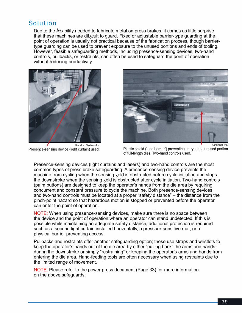
HazardIf the press brake can bend metal with ease, it is obvious that this same capacity can cause serious injuries to operators, including severed or broken arms, hands, ¿ngers, or any other part of the body. Although the actual operation of the press brake does not require the operator to place his or her hands or any part of the body into the point of operation, the close exposure to the closing dies still creates a signi¿cant risk. In addition, the stock can sometimes “whip” or bend up, creating a pinch-point hazard between it and the front face of the slide (A) or possibly “slapping” the operator if he or she is in the path of the rising material (B).
Installing and removing tooling provides the most direct exposure in the point of operation as the operator must place his or her hands between the two dies. The operator’s hands or arms can be severely crushed if the ram fell during setup.
Unprotected operating controls, especially foot pedals, can also introduce the possibility of accidental cycling.
Press brake
Steve D. Bensonthefabricator.com
39
Solut ionDue to the Àexibility needed to fabricate metal on press brakes, it comes as little surprise that these machines are dif¿cult to guard. Fixed or adjustable barrier-type guarding at the point of operation is usually not practical because of the fabrication process, though barrier-type guarding can be used to prevent exposure to the unused portions and ends of tooling. However, feasible safeguarding methods, including presence-sensing devices, two-hand controls, pullbacks, or restraints, can often be used to safeguard the point of operation without reducing productivity.
Presence-sensing devices (light curtains and lasers) and two-hand controls are the most common types of press brake safeguarding. A presence-sensing device prevents the machine from cycling when the sensing ¿eld is obstructed before cycle initiation and stops the downstroke when the sensing ¿eld is obstructed after cycle initiation. Two-hand controls (palm buttons) are designed to keep the operator’s hands from the die area by requiring concurrent and constant pressure to cycle the machine. Both presence-sensing devices and two-hand controls must be located at a proper “safety distance” – the distance from the pinch-point hazard so that hazardous motion is stopped or prevented before the operator can enter the point of operation.
NOTE: When using presence-sensing devices, make sure there is no space between the device and the point of operation where an operator can stand undetected. If this is possible while maintaining an adequate safety distance, additional protection is required such as a second light curtain installed horizontally, a pressure-sensitive mat, or a physical barrier preventing access.
Pullbacks and restraints offer another safeguarding option; these use straps and wristlets to keep the operator’s hands out of the die area by either “pulling back” the arms and hands during the downstroke or simply “restraining” or keeping the operator’s arms and hands from entering the die area. Hand-feeding tools are often necessary when using restraints due to the limited range of movement.
NOTE: Please refer to the power press document (Page 33) for more information on the above safeguards.
Rockford Systems Inc.
Presence-sensing device (light curtain) used.Cincinnati Inc.
Plastic shield (“end barrier”) preventing entry to the unused portion of full-length dies. Two-hand controls used.

40
If the use of physical barriers or devices is not feasible, safeguarding by “safe distance” is permitted if the employer meets the conditions described in Oregon OSHA Program Directive A-217 “Guarding: Power Press Brakes.” This safeguarding by maintaining a “safe distance” is limited to one-time-only fabrication of made-to-order or custom-made piece parts, such as small-quantity runs typically performed in “job shop” establishments. A “small-quantity run” means fabrication of more than one of the same piece part over a continuous timeframe of no more than four hours per month.
Under this instruction, the operator and helpers must not approach closer than necessary and, in no case, closer than four inches to the brake’s point of operation. The minimum safe distance of four inches must be measured from the exterior point of contact of the brake’s die closest to the worker’s ¿ngers holding and supporting a piece part. Finally, this “Safe Distance Safeguarding” program must contain written exposure prevention procedures, training, and enforcement criteria.
If more than one person is needed to operate, only one should be designated as the operator and controls should be furnished for each person. The operator should always make certain that any helpers are clear of the press before beginning the operation.
To avoid being pinched or struck by the work piece “whipping” up, never hold the material over the top of a previous bend, keep your hands underneath the work piece, and always keep your face and upper body out of the material’s path.
Before any tooling can be installed, the ram should be locked in the shut height position with the ram in its most extended position (on the upstroke). Once the press is locked into that position, the tooling can slide safely into the press. The gap between the ram and the bed should be just big enough to allow easy installation without the tooling falling out. Use safety blocks where tooling permits. Make sure the back gauge is high enough to prevent the piece part from slipping over the top of it, which can bring the operator’s hands and arms into the die.
To prevent accidental cycling, effectively cover all hand and foot controls.
As with any power press, a “no hands in die” policy should always be encouraged. Of course, there are times during setup where this exposure will occur and effective die setting procedures or energy-control procedures will address this. Furthermore, the safeguarding devices and strategies mentioned here should keep the operator’s hands and other body parts out of the die area during operation. Never reach between the tooling for any reason – reach around or walk behind the press brake when necessary. Barricade the back of the press to restrict access.
NOTE: Consider feasible safeguarding or proper material holding techniques if operating a press brake within a stationary ram and a sliding bed.
QMF Solutions
Quali¿ed and attentive operators are a must in maintaining safe press brake operations.
Rockford Systems Inc.
Pow er press brake — c ont inued

41
Referenc esGeneral Indust r y� Oregon OSHA Division 2/Subdivision O, 1910.212 – General Requirements for All Machines
� Oregon OSHA Program Directive A-217 – Guarding: Power Press Brakes
� ANSI B11.3 Power Press Brakes – Safety Requirements for Construction, Care, and Use
� ANSI B11.19 Safeguarding When Referenced by the Other B11 Machine Tool Safety Standards – Performance Criteria for the Design, Construction, Care, and Operation
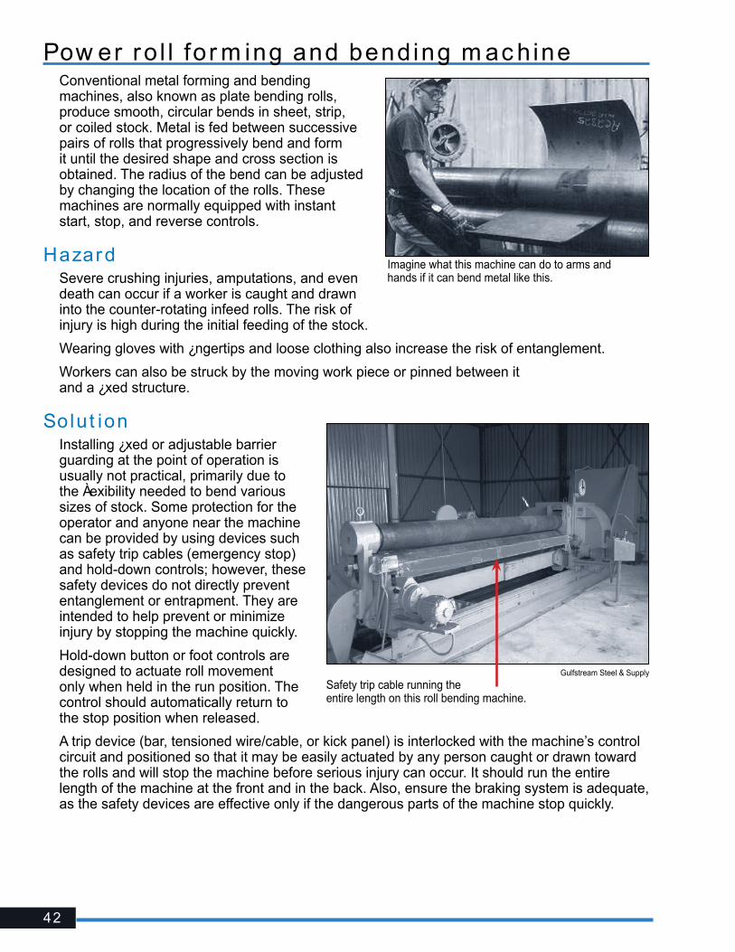
42
Pow er ro l l for m ing and bending m ac hineConventional metal forming and bending machines, also known as plate bending rolls, produce smooth, circular bends in sheet, strip, or coiled stock. Metal is fed between successive pairs of rolls that progressively bend and form it until the desired shape and cross section is obtained. The radius of the bend can be adjusted by changing the location of the rolls. These machines are normally equipped with instant start, stop, and reverse controls.
HazardSevere crushing injuries, amputations, and even death can occur if a worker is caught and drawn into the counter-rotating infeed rolls. The risk of injury is high during the initial feeding of the stock.
Wearing gloves with ¿ngertips and loose clothing also increase the risk of entanglement.
Workers can also be struck by the moving work piece or pinned between it and a ¿xed structure.
Solut ionInstalling ¿xed or adjustable barrier guarding at the point of operation is usually not practical, primarily due to the Àexibility needed to bend various sizes of stock. Some protection for the operator and anyone near the machine can be provided by using devices such as safety trip cables (emergency stop) and hold-down controls; however, these safety devices do not directly prevent entanglement or entrapment. They are intended to help prevent or minimize injury by stopping the machine quickly.
Hold-down button or foot controls are designed to actuate roll movement only when held in the run position. The control should automatically return to the stop position when released.
A trip device (bar, tensioned wire/cable, or kick panel) is interlocked with the machine’s control circuit and positioned so that it may be easily actuated by any person caught or drawn toward the rolls and will stop the machine before serious injury can occur. It should run the entire length of the machine at the front and in the back. Also, ensure the braking system is adequate, as the safety devices are effective only if the dangerous parts of the machine stop quickly.
Imagine what this machine can do to arms and hands if it can bend metal like this.
Gulfstream Steel & Supply
Safety trip cable running the entire length on this roll bending machine.
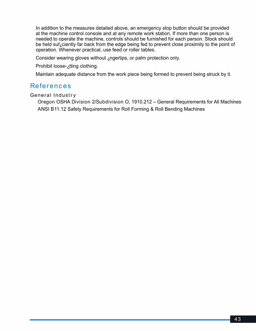
43
In addition to the measures detailed above, an emergency stop button should be provided at the machine control console and at any remote work station. If more than one person is needed to operate the machine, controls should be furnished for each person. Stock should be held suf¿ciently far back from the edge being fed to prevent close proximity to the point of operation. Whenever practical, use feed or roller tables.
Consider wearing gloves without ¿ngertips, or palm protection only.
Prohibit loose-¿tting clothing.
Maintain adequate distance from the work piece being formed to prevent being struck by it.
Referenc esGeneral Indust r y� Oregon OSHA Division 2/Subdivision O, 1910.212 – General Requirements for All Machines
� ANSI B11.12 Safety Requirements for Roll Forming & Roll Bending Machines
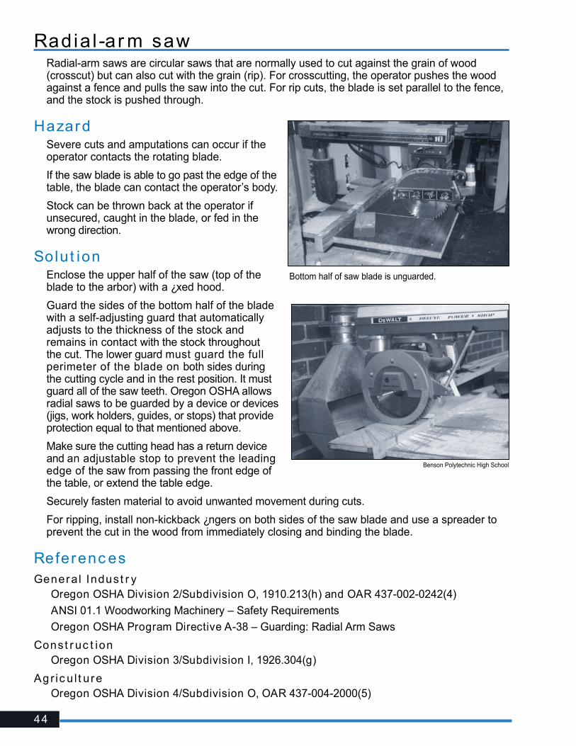
44
Radia l -ar m sawRadial-arm saws are circular saws that are normally used to cut against the grain of wood (crosscut) but can also cut with the grain (rip). For crosscutting, the operator pushes the wood against a fence and pulls the saw into the cut. For rip cuts, the blade is set parallel to the fence, and the stock is pushed through.
HazardSevere cuts and amputations can occur if the operator contacts the rotating blade.
If the saw blade is able to go past the edge of the table, the blade can contact the operator’s body.
Stock can be thrown back at the operator if unsecured, caught in the blade, or fed in the wrong direction.
Solut ionEnclose the upper half of the saw (top of the blade to the arbor) with a ¿xed hood.
Guard the sides of the bottom half of the blade with a self-adjusting guard that automatically adjusts to the thickness of the stock and remains in contact with the stock throughout the cut. The lower guard must guard the full perimeter of the blade on both sides during the cutting cycle and in the rest position. It must guard all of the saw teeth. Oregon OSHA allows radial saws to be guarded by a device or devices (jigs, work holders, guides, or stops) that provide protection equal to that mentioned above.
Make sure the cutting head has a return device and an adjustable stop to prevent the leading edge of the saw from passing the front edge of the table, or extend the table edge.
Securely fasten material to avoid unwanted movement during cuts.
For ripping, install non-kickback ¿ngers on both sides of the saw blade and use a spreader to prevent the cut in the wood from immediately closing and binding the blade.
Referenc esGeneral Indust r y� Oregon OSHA Division 2/Subdivision O, 1910.213(h) and OAR 437-002-0242(4)
� ANSI 01.1 Woodworking Machinery – Safety Requirements
� Oregon OSHA Program Directive A-38 – Guarding: Radial Arm Saws
Const r uc t ion� Oregon OSHA Division 3/Subdivision I, 1926.304(g)
Agr ic u l t ure� Oregon OSHA Division 4/Subdivision O, OAR 437-004-2000(5)
Bottom half of saw blade is unguarded.
Benson Polytechnic High School
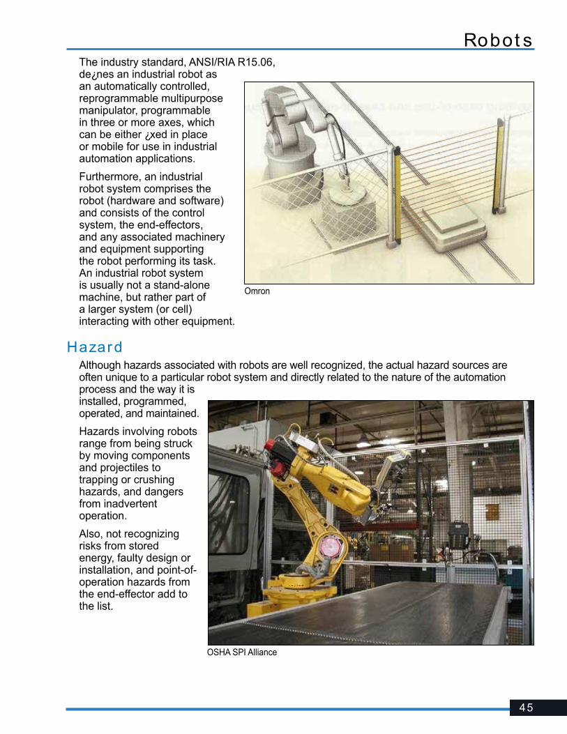
45
Robot sThe industry standard, ANSI/RIA R15.06, de¿nes an industrial robot as an automatically controlled, reprogrammable multipurpose manipulator, programmable in three or more axes, which can be either ¿xed in place or mobile for use in industrial automation applications.
Furthermore, an industrial robot system comprises the robot (hardware and software) and consists of the control system, the end-effectors, and any associated machinery and equipment supporting the robot performing its task. An industrial robot system is usually not a stand-alone machine, but rather part of a larger system (or cell) interacting with other equipment.
HazardAlthough hazards associated with robots are well recognized, the actual hazard sources are often unique to a particular robot system and directly related to the nature of the automation process and the way it is installed, programmed, operated, and maintained.
Hazards involving robots range from being struck by moving components and projectiles to trapping or crushing hazards, and dangers from inadvertent operation.
Also, not recognizing risks from stored energy, faulty design or installation, and point-of-operation hazards from the end-effector add to the list.
Omron
OSHA SPI Alliance
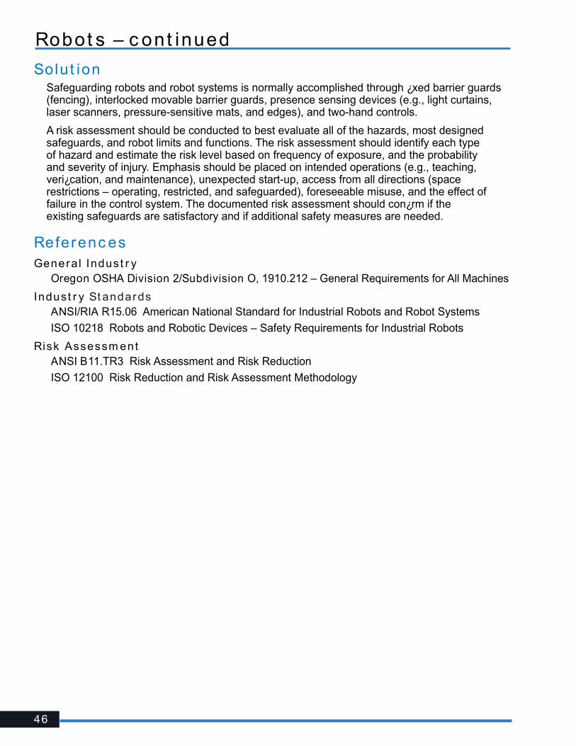
46
Solut ionSafeguarding robots and robot systems is normally accomplished through ¿xed barrier guards (fencing), interlocked movable barrier guards, presence sensing devices (e.g., light curtains, laser scanners, pressure-sensitive mats, and edges), and two-hand controls.
A risk assessment should be conducted to best evaluate all of the hazards, most designed safeguards, and robot limits and functions. The risk assessment should identify each type of hazard and estimate the risk level based on frequency of exposure, and the probability and severity of injury. Emphasis should be placed on intended operations (e.g., teaching, veri¿cation, and maintenance), unexpected start-up, access from all directions (space restrictions – operating, restricted, and safeguarded), foreseeable misuse, and the effect of failure in the control system. The documented risk assessment should con¿rm if the existing safeguards are satisfactory and if additional safety measures are needed.
Referenc esGeneral Indust r y� Oregon OSHA Division 2/Subdivision O, 1910.212 – General Requirements for All Machines
Indust r y St andards� ANSI/RIA R15.06 American National Standard for Industrial Robots and Robot Systems
� ISO 10218 Robots and Robotic Devices – Safety Requirements for Industrial Robots
Risk Assessm ent� ANSI B11.TR3 Risk Assessment and Risk Reduction
� ISO 12100 Risk Reduction and Risk Assessment Methodology
Robot s – c ont inued
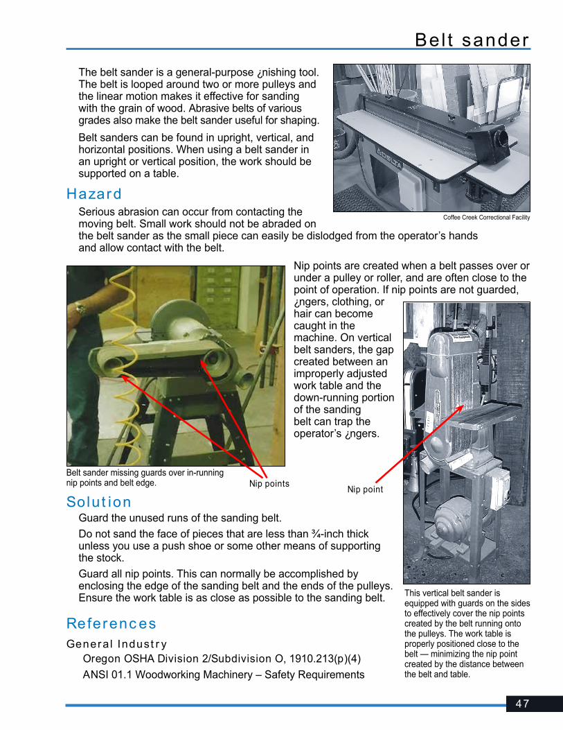
47
Bel t sander
The belt sander is a general-purpose ¿nishing tool. The belt is looped around two or more pulleys and the linear motion makes it effective for sanding with the grain of wood. Abrasive belts of various grades also make the belt sander useful for shaping.
Belt sanders can be found in upright, vertical, and horizontal positions. When using a belt sander in an upright or vertical position, the work should be supported on a table.
HazardSerious abrasion can occur from contacting the moving belt. Small work should not be abraded on the belt sander as the small piece can easily be dislodged from the operator’s hands and allow contact with the belt.
Nip points are created when a belt passes over or under a pulley or roller, and are often close to the point of operation. If nip points are not guarded, ¿ngers, clothing, or hair can become caught in the machine. On vertical belt sanders, the gap created between an improperly adjusted work table and the down-running portion of the sanding belt can trap the operator’s ¿ngers.
Coffee Creek Correctional Facility
This vertical belt sander is equipped with guards on the sides to effectively cover the nip points created by the belt running onto the pulleys. The work table is properly positioned close to the belt — minimizing the nip point created by the distance between the belt and table.
Solu t ionGuard the unused runs of the sanding belt.
Do not sand the face of pieces that are less than ¾-inch thick unless you use a push shoe or some other means of supporting the stock.
Guard all nip points. This can normally be accomplished by enclosing the edge of the sanding belt and the ends of the pulleys. Ensure the work table is as close as possible to the sanding belt.
Referenc esGeneral Indust r y � Oregon OSHA Division 2/Subdivision O, 1910.213(p)(4)
� ANSI 01.1 Woodworking Machinery – Safety Requirements
Belt sander missing guards over in-running nip points and belt edge. Nip points
Nip point
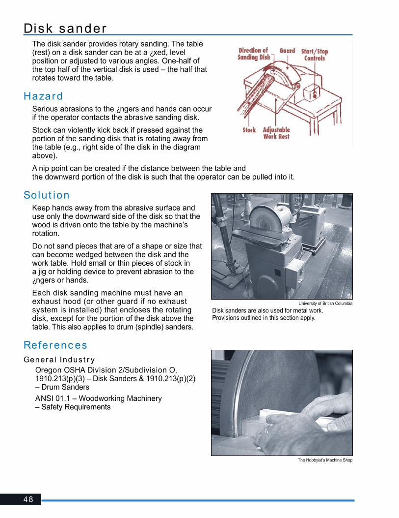
48
Disk sanderThe disk sander provides rotary sanding. The table (rest) on a disk sander can be at a ¿xed, level position or adjusted to various angles. One-half of the top half of the vertical disk is used – the half that rotates toward the table.
HazardSerious abrasions to the ¿ngers and hands can occur if the operator contacts the abrasive sanding disk.
Stock can violently kick back if pressed against the portion of the sanding disk that is rotating away from the table (e.g., right side of the disk in the diagram above).
A nip point can be created if the distance between the table and the downward portion of the disk is such that the operator can be pulled into it.
Solu t ionKeep hands away from the abrasive surface and use only the downward side of the disk so that the wood is driven onto the table by the machine’s rotation.
Do not sand pieces that are of a shape or size that can become wedged between the disk and the work table. Hold small or thin pieces of stock in a jig or holding device to prevent abrasion to the ¿ngers or hands.
Each disk sanding machine must have an exhaust hood (or other guard if no exhaust system is installed) that encloses the rotating disk, except for the portion of the disk above the table. This also applies to drum (spindle) sanders.
Referenc esGeneral Indust r y� Oregon OSHA Division 2/Subdivision O,
1910.213(p)(3) – Disk Sanders & 1910.213(p)(2) – Drum Sanders
� ANSI 01.1 – Woodworking Machinery – Safety Requirements
University of British Columbia
The Hobbyist’s Machine Shop
Disk sanders are also used for metal work. Provisions outlined in this section apply.

49
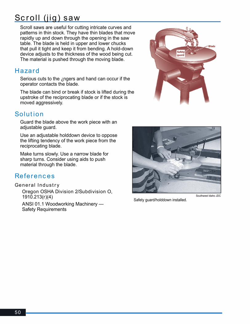
50
Sc ro l l (j ig ) sawScroll saws are useful for cutting intricate curves and patterns in thin stock. They have thin blades that move rapidly up and down through the opening in the saw table. The blade is held in upper and lower chucks that pull it tight and keep it from bending. A hold-down device adjusts to the thickness of the wood being cut. The material is pushed through the moving blade.
HazardSerious cuts to the ¿ngers and hand can occur if the operator contacts the blade.
The blade can bind or break if stock is lifted during the upstroke of the reciprocating blade or if the stock is moved aggressively.
Solut ionGuard the blade above the work piece with an adjustable guard.
Use an adjustable holddown device to oppose the lifting tendency of the work piece from the reciprocating blade.
Make turns slowly. Use a narrow blade for sharp turns. Consider using aids to push material through the blade.
Referenc esGeneral Indust r y� Oregon OSHA Division 2/Subdivision O,
1910.213(r)(4)
� ANSI 01.1 Woodworking Machinery — Safety Requirements
Southwest Idaho JDC
Safety guard/holddown installed.
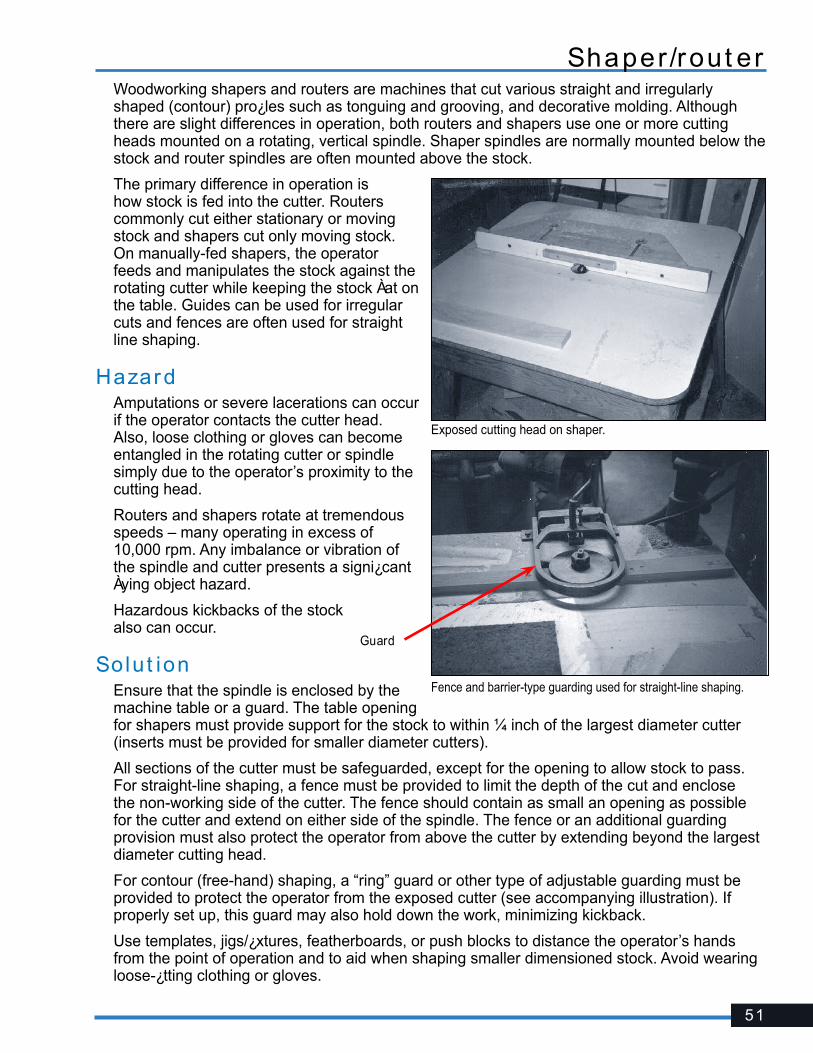
51
Shaper /rout erWoodworking shapers and routers are machines that cut various straight and irregularly shaped (contour) pro¿les such as tonguing and grooving, and decorative molding. Although there are slight differences in operation, both routers and shapers use one or more cutting heads mounted on a rotating, vertical spindle. Shaper spindles are normally mounted below the stock and router spindles are often mounted above the stock.
The primary difference in operation is how stock is fed into the cutter. Routers commonly cut either stationary or moving stock and shapers cut only moving stock. On manually-fed shapers, the operator feeds and manipulates the stock against the rotating cutter while keeping the stock Àat on the table. Guides can be used for irregular cuts and fences are often used for straight line shaping.
HazardAmputations or severe lacerations can occur if the operator contacts the cutter head. Also, loose clothing or gloves can become entangled in the rotating cutter or spindle simply due to the operator’s proximity to the cutting head.
Routers and shapers rotate at tremendous speeds – many operating in excess of 10,000 rpm. Any imbalance or vibration of the spindle and cutter presents a signi¿cant Àying object hazard.
Hazardous kickbacks of the stock also can occur.
Solut ionEnsure that the spindle is enclosed by the machine table or a guard. The table opening for shapers must provide support for the stock to within ¼ inch of the largest diameter cutter (inserts must be provided for smaller diameter cutters).
All sections of the cutter must be safeguarded, except for the opening to allow stock to pass. For straight-line shaping, a fence must be provided to limit the depth of the cut and enclose the non-working side of the cutter. The fence should contain as small an opening as possible for the cutter and extend on either side of the spindle. The fence or an additional guarding provision must also protect the operator from above the cutter by extending beyond the largest diameter cutting head.
For contour (free-hand) shaping, a “ring” guard or other type of adjustable guarding must be provided to protect the operator from the exposed cutter (see accompanying illustration). If properly set up, this guard may also hold down the work, minimizing kickback.
Use templates, jigs/¿xtures, featherboards, or push blocks to distance the operator’s hands from the point of operation and to aid when shaping smaller dimensioned stock. Avoid wearing loose-¿tting clothing or gloves.
Exposed cutting head on shaper.
Fence and barrier-type guarding used for straight-line shaping.
Guard

52
To minimize hazardous kickback, use extra care when shaping stock that contains cross grains or knots. Use a secure stop block where an interrupted cut is made. Do not back up the stock (check to see that the direction of rotation is as expected).
Ensure the cutting head is stable and does not vibrate excessively when operated at maximum recommended speeds.
Referenc esGeneral Indust r y� Oregon OSHA Division 2/Subdivision O, 1910.213(m)(1)
� ANSI 01.1 Woodworking Machinery – Safety Requirements
Shaper /rout er - c ont inued
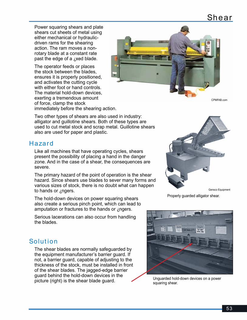
53
ShearPower squaring shears and plate shears cut sheets of metal using either mechanical or hydraulic-driven rams for the shearing action. The ram moves a non-rotary blade at a constant rate past the edge of a ¿xed blade.
The operator feeds or places the stock between the blades, ensures it is properly positioned, and activates the cutting cycle with either foot or hand controls. The material hold-down devices, exerting a tremendous amount of force, clamp the stock immediately before the shearing action.
Two other types of shears are also used in industry: alligator and guillotine shears. Both of these types are used to cut metal stock and scrap metal. Guillotine shears also are used for paper and plastic.
HazardLike all machines that have operating cycles, shears present the possibility of placing a hand in the danger zone. And in the case of a shear, the consequences are severe.
The primary hazard of the point of operation is the shear hazard. Since shears use blades to sever many forms and various sizes of stock, there is no doubt what can happen to hands or ¿ngers.
The hold-down devices on power squaring shears also create a serious pinch point, which can lead to amputation or fractures to the hands or ¿ngers.
Serious lacerations can also occur from handling the blades.
Solut ionThe shear blades are normally safeguarded by the equipment manufacturer’s barrier guard. If not, a barrier guard, capable of adjusting to the thickness of the stock, must be installed in front of the shear blades. The jagged-edge barrier guard behind the hold-down devices in the picture (right) is the shear blade guard.
Properly guarded alligator shear.
Gensco Equipment
Unguarded hold-down devices on a power squaring shear.
CPMFAB.com
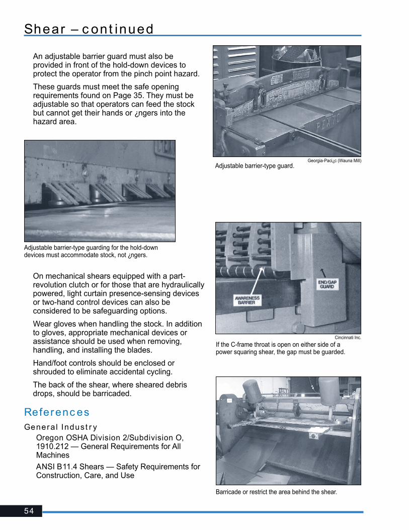
54
An adjustable barrier guard must also be provided in front of the hold-down devices to protect the operator from the pinch point hazard.
These guards must meet the safe opening requirements found on Page 35. They must be adjustable so that operators can feed the stock but cannot get their hands or ¿ngers into the hazard area.
Adjustable barrier-type guard.Georgia-Paci¿c (Wauna Mill)
Adjustable barrier-type guarding for the hold-down devices must accommodate stock, not ¿ngers.
If the C-frame throat is open on either side of a power squaring shear, the gap must be guarded.
Cincinnati Inc.
Barricade or restrict the area behind the shear.
On mechanical shears equipped with a part-revolution clutch or for those that are hydraulically powered, light curtain presence-sensing devices or two-hand control devices can also be considered to be safeguarding options.
Wear gloves when handling the stock. In addition to gloves, appropriate mechanical devices or assistance should be used when removing, handling, and installing the blades.
Hand/foot controls should be enclosed or shrouded to eliminate accidental cycling.
The back of the shear, where sheared debris drops, should be barricaded.
Referenc esGeneral Indust r y� Oregon OSHA Division 2/Subdivision O,
1910.212 — General Requirements for All Machines
� ANSI B11.4 Shears — Safety Requirements for Construction, Care, and Use
Shear – c ont inued
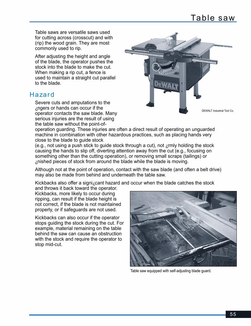
55
Table saw
Table saws are versatile saws used for cutting across (crosscut) and with (rip) the wood grain. They are most commonly used to rip.
After adjusting the height and angle of the blade, the operator pushes the stock into the blade to make the cut. When making a rip cut, a fence is used to maintain a straight cut parallel to the blade.
HazardSevere cuts and amputations to the ¿ngers or hands can occur if the operator contacts the saw blade. Many serious injuries are the result of using the table saw without the point-of-operation guarding. These injuries are often a direct result of operating an unguarded machine in combination with other hazardous practices, such as placing hands very close to the blade to guide stock (e.g., not using a push stick to guide stock through a cut), not ¿rmly holding the stock causing the hands to slip off, diverting attention away from the cut (e.g., focusing on something other than the cutting operation), or removing small scraps (tailings) or ¿nished pieces of stock from around the blade while the blade is moving.
Although not at the point of operation, contact with the saw blade (and often a belt drive) may also be made from behind and underneath the table saw.
Kickbacks also offer a signi¿cant hazard and occur when the blade catches the stock and throws it back toward the operator. Kickbacks, more likely to occur during ripping, can result if the blade height is not correct, if the blade is not maintained properly, or if safeguards are not used.
Kickbacks can also occur if the operator stops guiding the stock during the cut. For example, material remaining on the table behind the saw can cause an obstruction with the stock and require the operator to stop mid-cut.
Table saw equipped with self-adjusting blade guard.
DEWALT Industrial Tool Co.
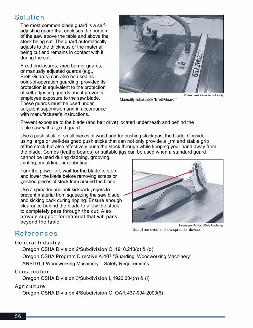
56
Solut ionThe most common blade guard is a self-adjusting guard that encloses the portion of the saw above the table and above the stock being cut. The guard automatically adjusts to the thickness of the material being cut and remains in contact with it during the cut.
Fixed enclosures, ¿xed barrier guards, or manually adjusted guards (e.g., Brett-Guards) can also be used as point-of-operation guarding, provided its protection is equivalent to the protection of self-adjusting guards and it prevents employee exposure to the saw blade. These guards must be used under suf¿cient supervision and in accordance with manufacturer’s instructions.
Prevent exposure to the blade (and belt drive) located underneath and behind the table saw with a ¿xed guard.
Use a push stick for small pieces of wood and for pushing stock past the blade. Consider using large or well-designed push sticks that can not only provide a ¿rm and stable grip of the stock but also effectively push the stock through while keeping your hand away from the blade. Combs (featherboards) or suitable jigs can be used when a standard guard cannot be used during dadoing, grooving, jointing, moulding, or rabbeting.
Turn the power off, wait for the blade to stop, and lower the blade before removing scraps or ¿nished pieces of stock from around the blade.
Use a spreader and anti-kickback ¿ngers to prevent material from squeezing the saw blade and kicking back during ripping. Ensure enough clearance behind the blade to allow the stock to completely pass through the cut. Also, provide support for material that will pass beyond the table.
Re fe r e n c e s Genera l Indust r y� Oregon OSHA Division 2/Subdivision O, 1910.213(c) & (d)
� Oregon OSHA Program Directive A-107 “Guarding: Woodworking Machinery”
� ANSI 01.1 Woodworking Machinery – Safety Requirements
Const r uc t ion � Oregon OSHA Division 3/Subdivision I, 1926.304(h) & (i)
Ag r ic u l t ure
� Oregon OSHA Division 4/Subdivision O, OAR 437-004-2000(6)
Coffee Creek Correctional Facility
Manually adjustable “Brett-Guard.”
Biesemeyer Products/Delta Machinery
Guard removed to show spreader device.
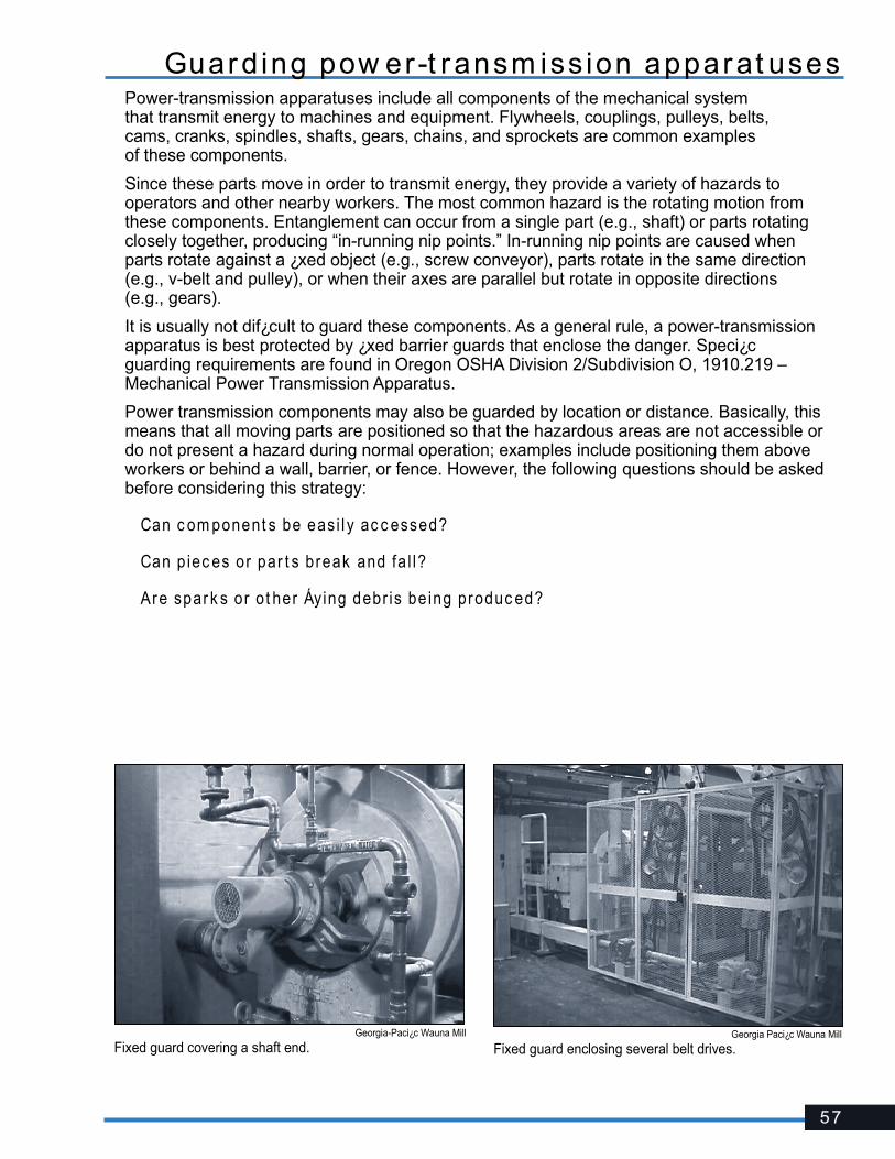
57
Guard ing pow er-t ransm iss ion apparat usesPower-transmission apparatuses include all components of the mechanical system that transmit energy to machines and equipment. Flywheels, couplings, pulleys, belts, cams, cranks, spindles, shafts, gears, chains, and sprockets are common examples of these components.
Since these parts move in order to transmit energy, they provide a variety of hazards to operators and other nearby workers. The most common hazard is the rotating motion from these components. Entanglement can occur from a single part (e.g., shaft) or parts rotating closely together, producing “in-running nip points.” In-running nip points are caused when parts rotate against a ¿xed object (e.g., screw conveyor), parts rotate in the same direction (e.g., v-belt and pulley), or when their axes are parallel but rotate in opposite directions (e.g., gears).
It is usually not dif¿cult to guard these components. As a general rule, a power-transmission apparatus is best protected by ¿xed barrier guards that enclose the danger. Speci¿c guarding requirements are found in Oregon OSHA Division 2/Subdivision O, 1910.219 – Mechanical Power Transmission Apparatus.
Power transmission components may also be guarded by location or distance. Basically, this means that all moving parts are positioned so that the hazardous areas are not accessible or do not present a hazard during normal operation; examples include positioning them above workers or behind a wall, barrier, or fence. However, the following questions should be asked before considering this strategy:
Can c om ponent s be easi l y ac c essed?
Can p iec es or par t s break and fa l l?
Are spar k s or o t her Áying debr is be ing produc ed?
Georgia-Paci¿c Wauna Mill
Fixed guard covering a shaft end.Georgia Paci¿c Wauna Mill
Fixed guard enclosing several belt drives.

58
Loc kout /Tagout
Safe w or k prac t ic es dur ing ser v ic e and repai rMany serious injuries and fatalities occur when somebody mistakenly thinks a machine is safely isolated from its energy sources or stored energy has been relieved or blocked. Approximately 120 workers are killed in the U.S. every year from a failure to effectively isolate hazardous energy.
Oregon OSHA’s Hazardous Energy Control standard, commonly referred to as “lockout/tagout,” covers the maintenance of machinery and equipment where unexpected startup, movement, or the release of stored energy can cause injury to workers. In general, the standard requires that all energy sources for machinery and equipment be turned off, isolated (disconnected), and physically locked out. Bleeding, relieving, or blocking other stored and residual energy must also be done to ensure isolation. The ¿nal important step before service begins is to verify all energy has been de-energized and isolated. These procedures, along with training and periodic audits, must be established and enforced.
Minor tool changes and adjustments, and other minor servicing activities, which take place during normal production operations, are not covered by this standard if they are routine, repetitive, and integral to the use of the equipment for production, provided that the work is performed using alternative measures that provide effective protection. Selection of an alternate control method must be based on a risk assessment of the machine, equipment, or process. The risk assessment must consider existing safeguards provided with the machine, equipment, or process that may need to be removed or modi¿ed to perform a given task. For example, when control circuits are used as part of the safeguarding system, the system must be designed to ensure protection as effective as a mechanical disconnect switch or master shutoff valve. A control-reliable dual-channel hardwired circuit of industrially rated components that satis¿es the design features as speci¿ed in ANSI B11.19, with a safety relay or safety PLC (programmable logic controllers) to ensure integrity and performance of the safeguarding system, must be used. Under all circumstances, the individual must have exclusive personal control over the means to maintain the state of the control circuit in a protective mode.
Referenc esGeneral Indust r y and Const r uc t ion� Oregon OSHA Division 2/Subdivision J, 1910.147 –The Control of Hazardous Energy
(Lockout/Tagout)
� Oregon OSHA Program Directive A-156 – Control of Hazardous Energy – Enforcement Policy and Inspection Procedures” (Lockout/Tagout)
� ISO 13849-1
� Oregon OSHA Publication – Lockout/Tagout: Oregon OSHA’s guide to controlling hazardous energy
Agr ic u l t ure� OAR 437-004-1275 – The Control of Hazardous Energy (Lockout/Tagout)
Am er ic an Nat ional St andards Inst i t u t e� ANSI/ASSE Z244.1 – Control of Hazardous Energy (Lockout/Tagout and Alternative Methods)
� ANSI B11.19 – Safeguarding when Referenced by the other B11 Machine Tool Safety Standards – Performance Criteria for Safeguarding

59
Risk Reduc t ion Hierarc hyA hierarchical approach is recommended when ¿rst approaching the safeguarding of a machine or operation. Safeguarding principles should be based on preventing access during dangerous motion or preventing dangerous motion during access.
1 . El im inat e t he hazard or ex posure t o t he hazard • Design/redesign the operation to remove exposure (e.g., automatic feeding/ejection,
designed enclosures)
• Locate the hazard where it is not accessible due to its location or distance
• Reduce energy
• Replacement/substitution
2 . Prevent ex posureFastened barrier guarding
• Metal or plastic enclosures
• Fixed metal or plastic enclosures, guarding, screens, fence, etc.
• Adjustable guarding
• Self-adjusting guarding
• Interlocked, ¿xed barrier guarding (interlock or other inputs meeting safety-related performance levels)
3 . Safeguard ex posureDevices that require adjustment or actuation by the user
• Presence-sensing devices (e.g., light curtains, scanners, mats)
• Gates
• Two-hand controls and trips
• Pullbacks and restraints
• Safety-related control system meeting appropriate performance levels related to functional safety (ANSI B11.19; ISO 13849; IEC 62061)
Remember, control inputs like presence-sensing devices and interlocks do not restrict or prevent access but only “sense” it. They rely entirely on their ability to both sense and switch (to instantly provide safety). It is imperative the control circuit meets appropriate performance levels related to functional safety.
For many years, the term “control reliability” has been mainly de¿ned by ANSI B11.19 addressing the safety performance of control circuits. However, the use of the term has declined in recent years due to the widespread acceptance of European Directives and International Standards such as ISO 13849 and IEC 62061. These standards provide a more complete and veri¿able means of specifying the safety performance level of control circuits [further de¿ning ¿ve circuit categories and ¿ve performance levels based on redundancy (duplication), diversity (different techniques), and monitoring (self-checking)]. “Safety-related functions,” “safety-related control system,” or “functional safety” are other terms commonly used these days.

60
4. Use adm in is t rat ive c ont ro ls and a ids t o supplem ent o t her c ont ro ls
• Reduce the occurrences of the task
• Provide information, instructions (i.e., manuals) and warnings (e.g., signs, symbols, markings, lights, alarms, awareness barriers)
• Appropriate hand tools, jigs, holders, push sticks, etc.
• Provide hands-on training and effective supervision
• Enforce safe work practices (e.g., safe job procedure, job hazard analysis)
Referenc es� Oregon OSHA www.orosha.org
� OSHA www.osha.gov
� National Institute of Occupational Safety and Health (NIOSH) www.cdc.gov/niosh
� Industry Standards ANSI B11.19 Performance Criteria for Safeguarding
� ISO 12100 Safety of Machinery
Risk Reduc t ion Hierarc hy – c ont inued
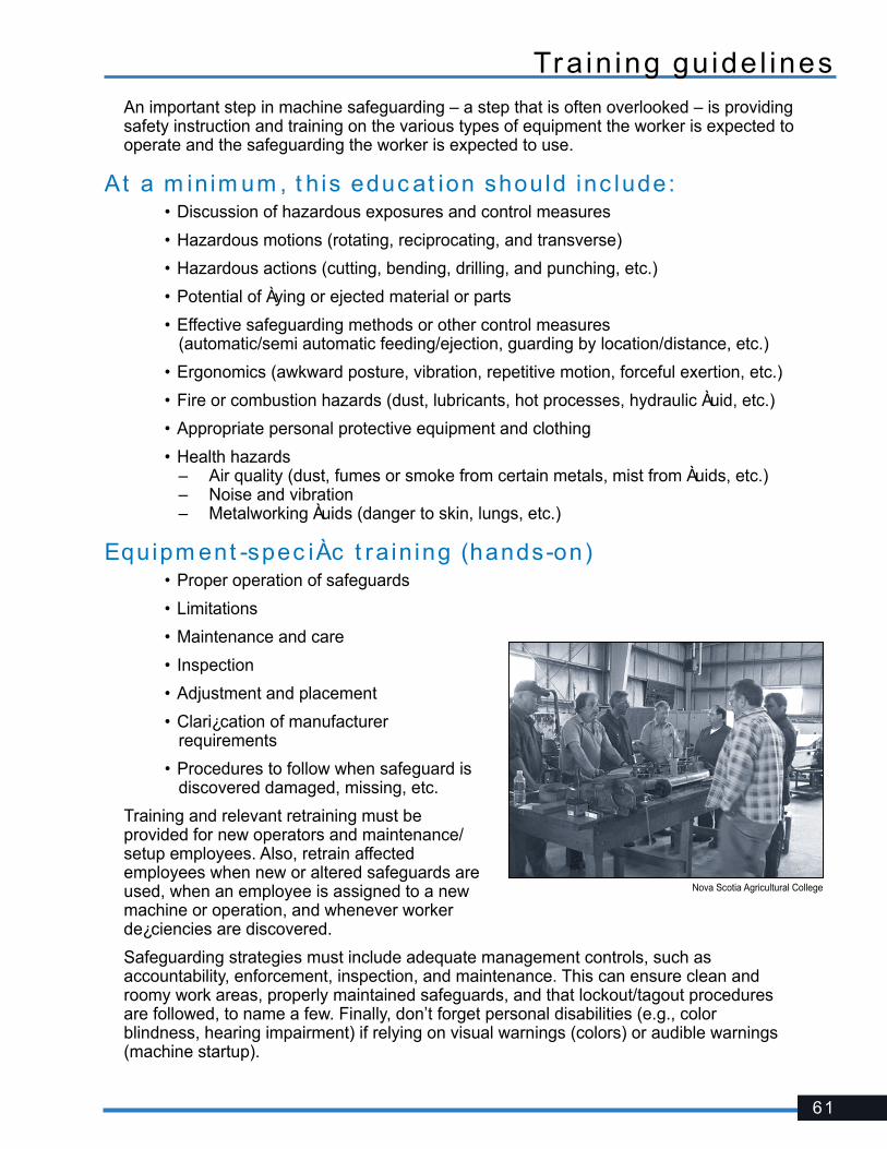
61
Tra in ing gu ide l inesAn important step in machine safeguarding – a step that is often overlooked – is providing safety instruction and training on the various types of equipment the worker is expected to operate and the safeguarding the worker is expected to use.
At a m in im um , t h is educ at ion should inc lude: • Discussion of hazardous exposures and control measures
• Hazardous motions (rotating, reciprocating, and transverse)
• Hazardous actions (cutting, bending, drilling, and punching, etc.)
• Potential of Àying or ejected material or parts
• Effective safeguarding methods or other control measures (automatic/semi automatic feeding/ejection, guarding by location/distance, etc.)
• Ergonomics (awkward posture, vibration, repetitive motion, forceful exertion, etc.)
• Fire or combustion hazards (dust, lubricants, hot processes, hydraulic Àuid, etc.)
• Appropriate personal protective equipment and clothing
• Health hazards – Air quality (dust, fumes or smoke from certain metals, mist from Àuids, etc.) – Noise and vibration – Metalworking Àuids (danger to skin, lungs, etc.)
Equipm ent -spec iÀc t ra in ing (hands-on) • Proper operation of safeguards
• Limitations
• Maintenance and care
• Inspection
• Adjustment and placement
• Clari¿cation of manufacturer requirements
• Procedures to follow when safeguard is discovered damaged, missing, etc.
Training and relevant retraining must be provided for new operators and maintenance/setup employees. Also, retrain affected employees when new or altered safeguards are used, when an employee is assigned to a new machine or operation, and whenever worker de¿ciencies are discovered.
Safeguarding strategies must include adequate management controls, such as accountability, enforcement, inspection, and maintenance. This can ensure clean and roomy work areas, properly maintained safeguards, and that lockout/tagout procedures are followed, to name a few. Finally, don’t forget personal disabilities (e.g., color blindness, hearing impairment) if relying on visual warnings (colors) or audible warnings (machine startup).
Nova Scotia Agricultural College

62
Bas ic safet y pr inc ip lesAlthough this guide addresses point-of-operation safeguarding for speci¿c machinery, it is also important to establish and enforce safe work practices when operating and maintaining all types of equipment and machinery.
The following list includes basic rules that apply to portable and ¿xed machinery:
Equipm ent (“ par t s” inc lude b lades, b i t s , sanding be l t s , d ies, g r ind ing s t ones)
• Follow the equipment manufacturer’s recommendations
• Use equipment only for the purpose for which its design is intended
• Operate the tool at the speed and tension speci¿ed by the manufacturer
• Inspect the equipment visually before use
• Remove unadjusted, defective, cracked, or worn parts from service
• Maintain sharp and clean parts
• When provided, use equipment with an exhaust or dust-collection system
• Use the appropriate size and type of part for the material and cutting action
• Check to see that guards, guides, and counterweights are properly adjusted and operable
• Avoid overheating the equipment
Wor k prac t ic es • Use only tools you can control easily
• Make sure hands are kept at a safe distance
• Follow safe procedures as outlined in the operator’s manual
• Always wear eye and face protection and other appropriate personal protective equipment
• Do not wear loose clothing or long hair that may become entangled
• Check to see that power cords are kept away from the line of cut and other moving parts
• Follow proper lockout/tagout procedures during service and repair
• Never defeat the guard to expose the blade
• Never reach under the saw, work piece, or any place you can’t see clearly
• Direct the operation away from your body
Wor k env i ronm ent • Practice good housekeeping – avoid crowded, cluttered conditions
• Make sure combustible or Àammable material is located away from spark-producing operations
• Provide adequate ventilation to reduce dust and other air contaminants
• Monitor noise levels and provide hearing protection when necessary
63
Glossar y of t er m s
Adjust able bar r ie r guard – A physical barrier requiring manual adjustment for various jobs.
Brake m oni t or – A sensor designed, constructed, and arranged to monitor the effectiveness of the press braking system.
Cont ro l re l iab i l i t y (a lso c a l led per for m anc e of safe t y-re lat ed func t ions) – A part of the system that controls hazardous motion of a machine. It ensures the machine will stop when required in the event of a single component failure within the system.
Devic e – A control or attachment that:
• Prevents a cycle if the operator’s hands are inadvertently in the point of operation
• Maintains the operator’s hands at a safe distance during the hazardous portion of a cycle
• Restrains the operator from inadvertently reaching into the point of operation
• Automatically withdraws the operator’s hands from the point of operation as the dies close
Fix ed (bar r ier ) guard – A guard that provides a physical restriction to a hazard.
Guard – A physical barrier that prevents entry of the operator’s hands or ¿ngers into the point of operation. A guard:
• Must prevent any contact to the machine hazard and must be installed to prevent contact from around, over, through, or under the guard
• Must not allow objects to fall into moving parts or be ejected toward a worker
• Must not create a pinch point between it and moving machine parts
• Must be af¿xed to the machine and remain secure
• Must facilitate its own inspection and allow for maintenance and lubrication
• Must offer maximum visibility of the point of operation consistent with the other requirements
• Must conform to other appropriate standards (ANSI, manufacturer speci¿cations, etc.)
In t er loc ked guard – A barrier that, when opened or removed, trips a control mechanism that stops a cycle or prevents a cycle until the guard returns to its safe position.
Poin t o f operat ion – The area on a machine where work is actually performed upon the material being processed.
Safe t y d is t anc e – A calculation of how far a person’s hand can move from the time it activates a device until the slide stops moving.
Sel f -ad just ing guar d – A physical barrier that adjusts by the movement of stock and returns to its rest position after the stock passes through.

64
ServicesOregon OSHA offers a wide variety of safety and health services to employers and employees:
Appeals 503-947-7426; 800-922-2689; [email protected]
• Provides the opportunity for employers to hold informal meetings with Oregon OSHA on concerns about workplace safety and health.
• Discusses Oregon OSHA’s requirements and clari¿es workplace safety or health violations.• Discusses abatement dates and negotiates settlement agreements to resolve disputed citations.
Conferences 503-378-3272; 888-292-5247, Option 1; [email protected]
• Co-hosts conferences throughout Oregon that enable employees and employers to learn and share ideas with local and nationally recognized safety and health professionals.
Consultative Services 503-378-3272; 800-922-2689; [email protected]
• Offers no-cost, on-site safety and health assistance to help Oregon employers recognize and correct workplace safety and health problems.
• Provides consultations in the areas of safety, industrial hygiene, ergonomics, occupational safety and health programs, assistance to new businesses, the Safety and Health Achievement Recognition Program (SHARP), and the Voluntary Protection Program (VPP).
Enforcement 503-378-3272; 800-922-2689; [email protected]
• Offers pre-job conferences for mobile employers in industries such as logging and construction.• Inspects places of employment for occupational safety and health hazards and investigates
workplace complaints and accidents.• Provides abatement assistance to employers who have received citations and provides
compliance and technical assistance by phone.• Public Education 503-947-7443; 888-292-5247, Option 2; [email protected]• Provides workshops and materials covering management of basic safety and health programs,
safety committees, accident investigation, technical topics, and job safety analysis.
Standards and Technical Resources 503-378-3272; 800-922-2689; [email protected]
• Develops, interprets, and gives technical advice on Oregon OSHA’s safety and health rules.• Publishes safe-practices guides, pamphlets, and other materials for employers and employees• Manages the Oregon OSHA Resource Center, which offers safety videos, books, periodicals,
and research assistance for employers and employees.
Need more information? Call your nearest Oregon OSHA of¿ce.
Salem Central Of¿ce 350 Winter St. NE, Room 430 Salem, OR 97301-3882
Phone: 503-378-3272 Toll-free: 800-922-2689 Fax: 503-947-7461 en Español: 800-843-8086
Website: www.orosha.org
BendRed Oaks Square1230 NE Third St., Suite A-115 Bend, OR 97701-4374 541-388-6066 Consultation: 541-388-6068
Eugene1140 Willagillespie, Suite 42 Eugene, OR 97401-2101 541-686-7562 Consultation: 541-686-7913
Medford1840 Barnett Road, Suite D Medford, OR 97504-8250 541-776-6030 Consultation: 541-776-6016
Pendleton200 SE Hailey Ave. Pendleton, OR 97801-3056 541-276-9175 Consultation: 541-276-2353
Portland1750 NW Naito Parkway, Suite 112 Portland, OR 97209-2533 503-229-5910 Consultation: 503-229-6193
Salem1340 Tandem Ave. NE, Suite 160 Salem, OR 97303 503-378-3274 Consultation: 503-373-7819


440-2980 (4/15) Oregon OSHA