manual sistema scada
DESCRIPTION
DESCRIPCION Y USO DEL SISTEMA SCADATRANSCRIPT
Operating Instruction Genset Control Project: Guangopolo II, 5301954 Rev./ Date / Status 0 / 25.11.2013/ Comm. Edition
461180_Operating Instruction Genset Control Commissioning Edition.doc Page 1 of 134
Alfred Kuhse GmbH TEL +49(0)4171 798-0 , FAX -117
Mid voltage level: 13,8kV/46kV 60Hz Control Voltage: 230V AC, 60Hz; 24 V DC Auxiliary Voltage: 127/230V AC, 60Hz
Operating Instruction Genset Control
Project : Guangopolo II, 5301954 Client MAN Diesel & TurboSE, Augsburg Client Order No.: 4500859942 46D Manufacturer: Alfred Kuhse GmbH D 21423 Winsen/Luhe TEL +49(0)4171 798-0 FAX -117 E-Mail [email protected]
Kuhse Comm. Number : 461180 Rev./ Date / Status 0 / 25.11.2013 / Comm. Edition Document No. : 461180_Operation Instruction.doc
Operating Instruction Genset Control Project: Guangopolo II, 5301954 Rev./ Date / Status 0 / 25.11.2013/ Comm. Edition
461180_Operating Instruction Genset Control Commissioning Edition.doc Page 2 of 134
Alfred Kuhse GmbH TEL +49(0)4171 798-0 , FAX -117
Table of Contents: Table of Contents: ............................................................................................................. 2�Revision History ................................................................................................................. 7�1� Principle Front View ................................................................................................ 8�2� Principle Description............................................................................................. 10�2.1� Purpose ............................................................................................................................................... 10�2.2� Properties ............................................................................................................................................ 10�3� Functional Descriptions of Operation and Indication Elements ....................... 12�3.1� Switches and Push Buttons ................................................................................................................. 12�3.1.1� Selector Switch – Operation Mode GCP/SCADA ............................................................................... 12�3.1.1.1� Purpose ............................................................................................................................................. 12�3.1.1.2� Properties .......................................................................................................................................... 12�3.1.2� Selector Switch – Alternator Voltage ................................................................................................... 14�3.1.2.1� Purpose ............................................................................................................................................. 14�3.1.2.2� Properties .......................................................................................................................................... 14�3.1.3� Selector Switch – Local Synchronization Manual/OFF/Automatic ...................................................... 15�3.1.3.1� Purpose ............................................................................................................................................. 15�3.1.3.2� Properties .......................................................................................................................................... 15�3.1.4� Control Switch – Manual Setting Voltage, Power Factor Lower/0/Higher ........................................... 17�3.1.4.1� Purpose ............................................................................................................................................. 17�3.1.4.2� Properties .......................................................................................................................................... 17�3.1.5� Control Switch – Manual Setting Speed, Frequency, Load Lower/0/Higher ....................................... 18�3.1.5.1� Purpose ............................................................................................................................................. 18�3.1.5.2� Properties .......................................................................................................................................... 18�3.1.6� Push Button Red – Emergency Stop................................................................................................... 19�3.1.6.1� Purpose ............................................................................................................................................. 19�3.1.6.2� Properties .......................................................................................................................................... 19�3.1.7� Push Button Black – Acknowledge/Reset ........................................................................................... 21�3.1.7.1� Purpose ............................................................................................................................................. 21�3.1.7.2� Properties .......................................................................................................................................... 21�3.1.8� Push Button Blue – Lamp Test ............................................................................................................ 22�3.1.8.1� Purpose ............................................................................................................................................. 22�3.1.8.2� Properties .......................................................................................................................................... 22�3.1.9� Push Button Green – Alternator CB ON .............................................................................................. 23�3.1.9.1� Purpose ............................................................................................................................................. 23�3.1.9.2� Properties .......................................................................................................................................... 23�3.1.10� Push Button Red - Alternator CB OFF ................................................................................................ 25�3.1.10.1� Purpose ............................................................................................................................................. 25�3.1.10.2� Properties .......................................................................................................................................... 25�3.2� Indications ........................................................................................................................................... 27�3.2.1� Signaling Column ................................................................................................................................ 27�3.2.1.1� Purpose ............................................................................................................................................. 27�3.2.1.2� Properties .......................................................................................................................................... 27�3.2.2� LED Position Indicator – Alternator Circuit Breaker ............................................................................ 29�3.2.2.1� Purpose ............................................................................................................................................. 29�3.2.2.2� Properties .......................................................................................................................................... 29�3.2.3� LED Position Indicator – Alternator Earthing Switch ........................................................................... 30�3.2.3.1� Purpose ............................................................................................................................................. 30�3.2.3.2� Properties .......................................................................................................................................... 30�3.2.4� LED Position Indicator – Alternator Neutral Earthing Switch .............................................................. 32�
Operating Instruction Genset Control Project: Guangopolo II, 5301954 Rev./ Date / Status 0 / 25.11.2013/ Comm. Edition
461180_Operating Instruction Genset Control Commissioning Edition.doc Page 3 of 134
Alfred Kuhse GmbH TEL +49(0)4171 798-0 , FAX -117
3.2.4.1� Purpose ............................................................................................................................................. 32�3.2.4.2� Properties .......................................................................................................................................... 32�3.2.5� Voltmeter – Alternator Voltage ............................................................................................................ 34�3.2.5.1� Purpose ............................................................................................................................................. 34�3.2.5.2� Properties .......................................................................................................................................... 34�3.2.6� Ammeter – Alternator Current ............................................................................................................. 35�3.2.6.1� Purpose ............................................................................................................................................. 35�3.2.6.2� Properties .......................................................................................................................................... 35�3.2.7� Double Voltmeter – Synchronization Voltage ...................................................................................... 36�3.2.7.1� Purpose ............................................................................................................................................. 36�3.2.7.2� Properties .......................................................................................................................................... 36�3.2.8� Double Frequency Meter – Synchronization Frequency ..................................................................... 37�3.2.8.1� Purpose ............................................................................................................................................. 37�3.2.8.2� Properties .......................................................................................................................................... 37�3.2.9� Synchronoscope .................................................................................................................................. 38�3.2.9.1� Purpose ............................................................................................................................................. 38�3.2.9.2� Properties .......................................................................................................................................... 38�3.3� Units .................................................................................................................................................... 39�3.3.1� Automatic Synchronization Unit .......................................................................................................... 39�3.3.1.1� Purpose ............................................................................................................................................. 39�3.3.1.2� Properties .......................................................................................................................................... 39�3.3.2� Multifunctional Monitoring Unit (MMU) – Siemens Sentron PAC3200 ................................................ 41�3.3.2.1� Purpose ............................................................................................................................................. 41�3.3.2.2� Properties .......................................................................................................................................... 41�3.3.2.3� Operation .......................................................................................................................................... 41�3.4� Visualization ........................................................................................................................................ 43�3.4.1� Panel PC ............................................................................................................................................. 43�3.4.1.1� Purpose ............................................................................................................................................. 43�3.4.1.2� Properties .......................................................................................................................................... 43�3.5� Alternator Protection ............................................................................................................................ 45�3.5.1� Alternator Prote ction Device ............................................................................................................... 45�3.5.1.1� Purpose ............................................................................................................................................. 45�3.5.1.2� Properties .......................................................................................................................................... 45�4� Operating Scenarios ............................................................................................. 47�4.1� Synchronization of Circuit Breakers .................................................................................................... 47�4.1.1� Synchronization Principles .................................................................................................................. 47�4.1.2� Synchronization Operating Scenarios ................................................................................................. 48�4.1.2.1� Automatic Synchronization from GCP .............................................................................................. 48�4.1.2.2� Manual Synchronization from GCP .................................................................................................. 49�4.1.2.3� Automatic Synchronization from SCADA ......................................................................................... 50�4.1.2.4� Principle Control and Operating Philosophy Alternator Circuit Breaker and Excitation ................... 51�5� Overview diagramms ............................................................................................ 55�5.1� Overall Single line diagram ................................................................................................................. 55�5.2� Data structure GCP PLC ..................................................................................................................... 56�5.3� Protecion and measuring scheme GCP ............................................................................................. 57�5.4� Power Plant Operation modes ............................................................................................................ 58�5.5� Front View of Engine Control Panel +ECPx ........................................................................................ 59�5.6� Engine Auxiliary Panel +EAPx ............................................................................................................ 60�6� Engine control functions ...................................................................................... 61�6.1� Push button of engine control at PC touch panel ................................................................................ 61�6.2� Start procedure of engine in GCP mode ............................................................................................. 61�6.3� Start procedure of engine in SCADA mode ........................................................................................ 63�6.4� “Local Remote” switch 1HZ1012 at engine ......................................................................................... 63�6.5� Generator Synchronisation .................................................................................................................. 64�
Operating Instruction Genset Control Project: Guangopolo II, 5301954 Rev./ Date / Status 0 / 25.11.2013/ Comm. Edition
461180_Operating Instruction Genset Control Commissioning Edition.doc Page 4 of 134
Alfred Kuhse GmbH TEL +49(0)4171 798-0 , FAX -117
6.5.1� Parameter list for Synchronisation Monitoring .................................................................................... 64�6.5.2� Generator circuit breaker monitoring ................................................................................................... 65�6.6� Load controller description .................................................................................................................. 66�6.6.1� Settings of load controller GCP ........................................................................................................... 66�6.6.2� Monitoring of control function .............................................................................................................. 67�6.7� Loading of Engine................................................................................................................................ 68�6.8� Limitations in load range by the PCU (power control unit) .................................................................. 69�6.8.1� Load reduction dependent on ambient air temperature. ..................................................................... 69�6.8.2� Load reduction because of too high exhaust gas temperature before turbine. ................................... 70�6.9� PCU Parameter list (example) ............................................................................................................. 71�6.10� Further load limitations ........................................................................................................................ 72�6.11� Exhaust Gas Temperature Monitoring ................................................................................................ 73�6.11.1� Functional Description ......................................................................................................................... 73�6.11.2� Exhaust gas temperature monitoring functions ................................................................................... 76�Monitoring maximal value at cylinder ............................................................................................................... 76�Monitoring mean value deviation at cylinder .................................................................................................... 76�Monitoring maximal value before turbo charger ............................................................................................... 77�Temperature value after turbo charger ............................................................................................................ 77�Reset 77�6.12� Charge air temperature control TC6180 with 01MJG32AA010-M01 (MOV003) ................................ 78�6.12.1� Parameter list charge air temperature control ..................................................................................... 79�•� CHATCO curve ................................................................................................................................. 80�6.12.2� Function of controller ........................................................................................................................... 80�•� Monitoring of the control valve .......................................................................................................... 80�6.12.3� Selection operating mode .................................................................................................................... 80�Monitoring of the control valve ..................................................................................................................... 80�6.12.4� Allumatic .............................................................................................................................................. 81�Operation Modes ............................................................................................................................................ 81�6.12.5� Calculating the dewpoint temperature in normal mode ....................................................................... 82�6.12.6� Calculating the dewpoint temperature in failure mode ........................................................................ 83�6.12.7� Achievement of the optimal charge air temperature ........................................................................... 83�Allumatic Mode ............................................................................................................................................... 83�CHATCO Mode ................................................................................................................................................ 83�6.12.8� Alarms ................................................................................................................................................. 84�6.12.9� Emergency Stop .................................................................................................................................. 84�6.13� HT cooling water control valve 01MJG31AA010-M01 via TC3180 with MOV 002 ............................. 86�6.13.1� Parameter list HT cooling water controller .......................................................................................... 88�•� Monitoring of the control valve .......................................................................................................... 88�6.14� LT cooling water control valve 01MJG32AA025-M01 TC3202 with MOV004: ................................... 89�6.14.1� Parameter LT cooling water control .................................................................................................... 90�6.15� Slow turn .............................................................................................................................................. 90�6.15.1� Running sequence slow turn ............................................................................................................... 90�6.15.2� Parameter slow turn ............................................................................................................................ 91�6.15.3� Signal progression for direction of rotation recognition ....................................................................... 91�6.16� Ajdusting instruction of software PID-controller .................................................................................. 92�6.17� Splash oil ............................................................................................................................................. 93�6.17.1� General ................................................................................................................................................ 93�6.17.2� Subfunctions ........................................................................................................................................ 94�6.17.3� Monitoring Regarding Maximum Value Exceeding ............................................................................. 94�6.17.4� Monitoring Regarding Mean Value Deviation ...................................................................................... 94�6.17.5� Wire Break ........................................................................................................................................... 95�6.17.6� Not Plausible ....................................................................................................................................... 95�6.17.7� Monitoring “active” ............................................................................................................................... 95�6.17.8� TIMER (INTERGRATED) .................................................................................................................... 95�
Operating Instruction Genset Control Project: Guangopolo II, 5301954 Rev./ Date / Status 0 / 25.11.2013/ Comm. Edition
461180_Operating Instruction Genset Control Commissioning Edition.doc Page 5 of 134
Alfred Kuhse GmbH TEL +49(0)4171 798-0 , FAX -117
6.18� Generator power factor controller ........................................................................................................ 96�6.19� Testing of shut down valve X-1SZV1012 ............................................................................................ 97�6.20� CONTROL OF INTAKE AIR SYSTEM ................................................................................................ 98�6.20.1� Charge Air Blow-off System (xxMJQ61BR010/14) ............................................................................. 98�•� Interfaces .......................................................................................................................................... 98�•� Malfunction ........................................................................................................................................ 99�•� Alarms ............................................................................................................................................... 99�•� Start requirements ............................................................................................................................ 99�•� Normal operation: manual local ........................................................................................................ 99�•� Normal operation: manual remote .................................................................................................... 99�•� Normal operation: automatic remote ................................................................................................ 99�•� Normal operation: automatic local .................................................................................................... 99�•� Parameters Intake Air System ........................................................................................................ 100�6.20.2� General intake air instrumentation .................................................................................................... 101�•� Interfaces ........................................................................................................................................ 101�•� Malfunction ...................................................................................................................................... 101�•� Alarms ............................................................................................................................................. 102�•� Start requirements .......................................................................................................................... 102�•� Normal operation: manual local ...................................................................................................... 102�•� Normal operation: manual remote .................................................................................................. 102�•� Normal operation: automatic remote .............................................................................................. 102�•� Normal operation: automatic local .................................................................................................. 102�6.21� Princip of auxiliaries Operation modes .............................................................................................. 103�6.21.1� Manual Local Mode Auxiliary Drives ................................................................................................. 104�6.21.2� Manual Remote Mode Auxiliary Drives ............................................................................................. 105�6.21.3� Automatic Remote Mode Auxiliary Drives ......................................................................................... 106�6.21.4� Automatic Local Mode Auxiliary Drives ............................................................................................. 107�6.21.5� Double pumps ................................................................................................................................... 108�6.21.6� Manual pump switching ..................................................................................................................... 109�6.21.7� Double Starter Pumps, Master Selection Philosophy ....................................................................... 109�7� LV ENGINE Auxiliaries Panel +EAPx ................................................................. 113�7.1� LV ENGINE Auxiliaries Panel +EAPx frontview ................................................................................ 114�7.2� Pre lubrication pump 01MJV21AP030-M01 (P007) on MOD006 ...................................................... 115�7.2.1� Start prelubrication ............................................................................................................................ 115�•� Parameter Start prelubrication ........................................................................................................ 116�7.2.2� Cooling down the engine in case of shutdown .................................................................................. 116�7.2.3� Parameter: Cooling down function .................................................................................................... 116�7.3� Generator heating 01MKA01AH010 (H100) ..................................................................................... 117�7.4� Cylinder Lubrication 01MKA01AH010 (1EM2470) ............................................................................ 118�7.4.1� Area of application ............................................................................................................................. 118�7.4.2� Vögele System .................................................................................................................................. 118�7.4.3� Process sequence: Cylinder lubrication ............................................................................................ 119�•� Manual operation "Cylinder lubrication ON" ................................................................................... 119�•� Manual operation "Running-in mode" ............................................................................................. 119�•� Automatic operation ........................................................................................................................ 119�•� Control response in the event of failure of the input signals ........................................................... 119�•� Parameter: Cylinder lubrication ...................................................................................................... 120�7.5� Nozzle cooling water module 01MJG34AC010 (MOD005) ............................................................... 121�7.5.1� Parameters Nozzle cooling water module X0PAB48AC001 (MOD005) ........................................... 121�7.6� Fuel oil module 01END56AP010 (MOD008), HFO / light fuel oil (LFO)-Operation .......................... 122�Diesel operation ............................................................................................................................................. 122�HFO operation ................................................................................................................................................ 122�7.7� HT cooling water preheating module 01MJG31AP020-M01 (P070 on MOD004) ............................ 124�
Operating Instruction Genset Control Project: Guangopolo II, 5301954 Rev./ Date / Status 0 / 25.11.2013/ Comm. Edition
461180_Operating Instruction Genset Control Commissioning Edition.doc Page 6 of 134
Alfred Kuhse GmbH TEL +49(0)4171 798-0 , FAX -117
7.8� Lube oil separator module 01MJV22AT010 (MOD007 ..................................................................... 125�7.9� Lubrication oil valve xxMJV23AA202-Y01 on MOD057 (SOV 2303) ................................................ 126�7.9.1� Value Parameter Lubrication oil valve xxMJV23AA202-Y01 (SOV 2303) ........................................ 127�7.10� Power house ventilator 1 / 2 xxUMF15AN010-M01 / xxUMF15AN010-M02 .................................... 128�7.10.1� Normal operation automatic remote .................................................................................................. 128�7.10.2� Operation manual remote – Powerhouse ventilation system ............................................................ 129�7.10.3� Operation manual local – Powerhouse ventilation system................................................................ 130�7.10.4� Malfunctions ...................................................................................................................................... 131�7.10.5� Alarms ............................................................................................................................................... 132�7.11� DO Shut Off Valve Before Booster Module 01EGD53AA202-Y01 ................................................... 133�7.12� HFO Shut Off Valve Before Engine 01END56AA202-Y01 ............................................................... 133�
Operating Instruction Genset Control Project: Guangopolo II, 5301954 Rev./ Date / Status 0 / 25.11.2013/ Comm. Edition
461180_Operating Instruction Genset Control Commissioning Edition.doc Page 7 of 134
Alfred Kuhse GmbH TEL +49(0)4171 798-0 , FAX -117
�������������
�������� ������� ������� ���� �������������� ������
� ��������� ���� �� �! �" #$%
� ��������� ���� &' �� �" ������������(
Operating Instruction Genset Control Project: Guangopolo II, 5301954 Rev./ Date / Status 0 / 10.09.2013/ Comm. Edition
���������� ������������������������������
�
8 (134)
2013-07-17 Revision A in work
1 PRINCIPLE FRONT VIEW
Operating Instruction Genset Control Project: Guangopolo II, 5301954 Rev./ Date / Status 0 / 10.09.2013/ Comm. Edition
���������� ������������������������������
�
9 (134)
2013-07-17 Revision A in work
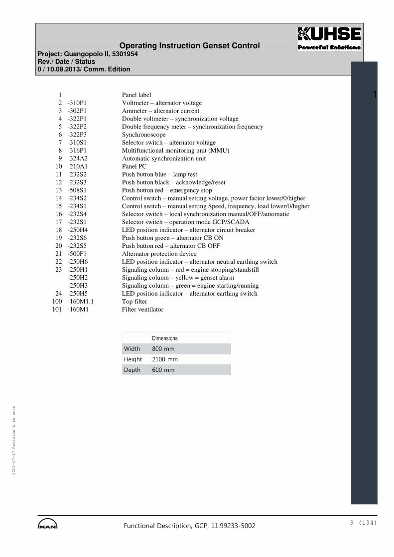
1 Panel label 2 -310P1 Voltmeter – alternator voltage 3 -302P1 Ammeter – alternator current 4 -322P1 Double voltmeter – synchronization voltage 5 -322P2 Double frequency meter – synchronization frequency 6 -322P3 Synchronoscope 7 -310S1 Selector switch – alternator voltage 8 -316P1 Multifunctional monitoring unit (MMU) 9 -324A2 Automatic synchronization unit 10 -210A1 Panel PC 11 -232S2 Push button blue – lamp test 12 -232S3 Push button black – acknowledge/reset 13 -508S1 Push button red – emergency stop 14 -234S2 Control switch – manual setting voltage, power factor lower/0/higher 15 -234S1 Control switch – manual setting Speed, frequency, load lower/0/higher 16 -232S4 Selector switch – local synchronization manual/OFF/automatic 17 -232S1 Selector switch – operation mode GCP/SCADA 18 -250H4 LED position indicator – alternator circuit breaker 19 -232S6 Push button green – alternator CB ON 20 -232S5 Push button red – alternator CB OFF 21 -500F1 Alternator protection device 22 -250H6 LED position indicator – alternator neutral earthing switch 23 -250H1 Signaling column – red = engine stopping/standstill -250H2 Signaling column – yellow = genset alarm -250H3 Signaling column – green = engine starting/running 24 -250H5 LED position indicator – alternator earthing switch 100 -160M1.1 Top filter 101 -160M1 Filter ventilator
�
� �����������
������ ���!!�
" �#��� �����!!�
� ���� $���!!�
461180_Operating Instruction Genset Control Commissioning Edition.doc Page 10 of 134
2 PRINCIPLE DESCRIPTION
2.1 Purpose
%� �����&� �� ����������� '�������������� ���������� �(�� ���� �# �� ��& �#�� ����� �����'������ ����)���� ����
2.2 Properties
%� ����������� ������� �����������!���
%������ �����������*��*�+� ���� ��! ���,�� ������� �*�! ��������������&-����%.��"����)� ��)�$��!!'�����# ��*���*����!������#�/������������������+���� ������*����������/�������,, ��#�0 ���%� ������ ( �����0 +� �����, ����� ���*��!��� �,����!��%� ������#����� �1 ��,+�������*��������*�!���� ������*�� ���%� ��� ��#���/�������0 ����� ������� ��*������/ ������+�������2�����3��%� ��� ����� ������� #� ����4�5����� ������-26�7�����%� ��� �������#���#����!������� ����*�/����� ���+ �/����#� ��68�� ! �������/��#��� �# �� ��������& �#�� ��������#9���������# �� ���!�� �#�� �����9������#'���
%� ���������/ ������+�*����������������(�� ��*��!���2�����3�:�.�������,�������+�� !������ �����53���������� ��/�������� ��� �,+��� #�� ����/ ������+������2�����3�9�����53��2�� ��� �,�** ��!��� �*�������53���/ ������+������� #�� ��������(�� ���������������/ ������+�*����� ��������� ��������6�������� ��*����������� �����������
%� ��6��&���#�!!, �6�#��������� �'�����.� ! ���.4;2%4��.+�� !�.7�5���/������ � ����1 ��49<�� ���� �+�8%���;��%� ��������� =���� ��/������������� ����*����� ���������� �(���������!��������#��%/���� ����#�!�� ��� �� ��, �,+���/����>�����&��'����.�2�2�&� !�� '��%� �� ��������������,� 0 ���+�������1��������, ���� �/����������!���� �����!�����+�������1������ (�� ����!��+�/������#� �9�/ ���/���� ��*���(��# ����*� =� ��+�����, �(��# ����*� =� ��+�! � �����68���+����������� ��������� ��+�!���� ���+�������1������� �0�� +��%� �� �������*��� �����+�������1�����!�� ���������, �/������/�����*�������+�������1�������
2��#�������! ����� ��(��! � ��/����(��# ��/����������!! � ���2������!���� ��;;:�&;���*��������;��������#�:���'����(�� ���� (��� �������������� ��6�����!���������� ���������� *��%/��! �����#�������� ���*������( ���/ �������/ ��*������������� ����(�� ����
%� ��������� =���� ��/�����!�!�����#�!��*��� �� ��������������������������*����� ���������,� 0 ����� � �����#����� ���� �����#��/�������������,�������*�����������,� 0 �������#������ ���#��%� �!��� �������� ��0��/ �# 9� � ��� �� �1 ��,+������!���� ��,���������
%� �8;8-�8?�@�.%<��,�������������� � �#�� ���� ����� �� ��������������,� 0 ����������� �# �� ���)���� ������ � )��� ���� �� �������%� �2� ���������� ���������� �1 ��,+����#���!���*������������ ������� +���
Operating Instruction Genset Control Project: Guangopolo II, 5301954 Rev./ Date / Status 0 / 10.09.2013/ Comm. Edition
461180_Operating Instruction Genset Control Commissioning Edition.doc Page 11 of 134
Alfred Kuhse GmbH TEL +49(0)4171 798-0 , FAX -117
�
%� ���� ���,����������� �����*�,�������� ����#��� ��6����� �;;:������ ����� ������� +��%� ������������ �� ������� �� ������! ���!�(��# ��/����# ������� �� ���� �����#��/����# ��(������/�� ������ ��������
%� ����� ������������ ��# �� ��� � ���� ���������� �����&��!!������������ '������ ��*������*�,���*�, �������������#�<6;��&<�����6��0�;��� '�*�������������(�����/�� ������ ������*�����#���� (���*����* �+��%� ����� ����������� �*�� �*�#����#����A���&A�� ����������� '������ ��(������/�� ������ ������*�����#���� (���*����* �+��%� ����� ����������� �.�2�2��+�� !����� �1 ��(������� ��8�� �� ���
Operating Instruction Genset Control Project: Guangopolo II, 5301954 Rev./ Date / Status 0 / 10.09.2013/ Comm. Edition
461180_Operating Instruction Genset Control Commissioning Edition.doc Page 12 of 134
Alfred Kuhse GmbH TEL +49(0)4171 798-0 , FAX -117
3 FUNCTIONAL DESCRIPTIONS OF OPERATION AND INDICATION ELEMENTS
3.1 Switches and Push Buttons
3.1.1 Selector Switch – Operation Mode GCP/SCADA
��������
3.1.1.1 Purpose
%� ����9.�2�2��/�����&�7'�� ����*��/��#��� ������!�� �>�
• �)�*• ���$�$
3.1.1.2 Properties
����������� ���
%� ����9.�2�2��/�����&�7'���������#��
%� �� ������������(���������������+��� ��������(��� ������** � ������������
4������ ����, �/ ���� ��������!�# ! �������� ��������!�# ! ����%���! ���������(����# �� �����!�# ! �������� �� � ��*�� !�� ��� ����!�# ! ���&���'��
�������� ���� ���������
%� � �������9� !�� ��/��������� � �#�� ��4*�������/����������������������������������������*��!��������.�2�2�������������, ��
8( �+��/������#�/��, �� ���� �����.�2�2������ ��� �������� ( �����
8( �+��/������#��0 ���� ��� � ��� ��������������,� 0 ��&�A'������ �!���� !�� �!�� ��%����(������������*��+�������1�����,+����#��#��� ����9.�2�2�!�� ��
4*��� ��A������� ����� ��/������#��� ��B�����# ��� �!�� ��*��� ��A��
8( �+��/������#�� �!��� ���������#��+�������1��������� ����*��� �� �������
���� ��������� ���� ���������
4������������������������ ! �������� ���������� ��� ����&��'�� ����( ������ �, ��
4��.�2�2������������� ��� ���������� ������������,�� ��� )� ����*��� >�
• � ! �# ��+������,������&��'�
Operating Instruction Genset Control Project: Guangopolo II, 5301954 Rev./ Date / Status 0 / 10.09.2013/ Comm. Edition
461180_Operating Instruction Genset Control Commissioning Edition.doc Page 13 of 134
Alfred Kuhse GmbH TEL +49(0)4171 798-0 , FAX -117
• ��0��/ �# 9� � ��,������&��'������� �,���������� ��� ����
• �!��� ���,������&��'�
%� � ! �# ��+������,������&��'����/+���� �, �, ��� ��*��* �+�� ��������� � �� ����*��� �� ������!�� ��
2������������������ ���� � �� ����*��� �� ���������������*��� ����9.�2�2��/�����&�7'��
%� �*���������*��� �� ���������� ������� (�� �&��'���������� � �� ����*��� �����������*��� ����9.�2�2��/�����&�7'��
4����������������� �# �� �����/+������� ����!�# ! ����������!����!�� ��
A+����#��#�*��!��������.�2�2��� �# �� ����+��������!�# ! ����������!����!�� �&4���(�������� ����#�/��, ��0 ���( �'��
%� ����!�# ! ����������!����!�� �!����, �� �� ��,+��� ��� �������.�2�2��*��� �# �� ���������� ������ ���!!������!�# ! ���&!�� ����!�# ! ����������!����!�� '��%����!�� ������+�(�, ������ �.�2�2�!�� ���������+�, �� �� ����.�2�2��
�� �����#��#�*��!��� ����������.�2�2���������� �# �� �����# ���!! ��� +�������� �!�� ����!�# ! ����������!����!�� ��
6���!�# ! ����������!����!�� �! ���������(����� �������*��� ����� ��������,+��� ��� ������
6���!�# ! ����������!����!�� �! ������!!���� �������*��� ����� ���������,+��� ������6�����!!������!�# ! �������� �>���������#����/ ��*����������#������9�������+�������1������������ ����#��*�# �� ���
����!�� ���*��!������� ��� ����� ��C6���;�# ! ��D��
Remarks:��2����# ��*��� �� ������!�� ���� �����*���! ������# ��*��� � �#�� �� �#���� � �#�� �������������#���������#����������/����8)� �����>�%� ��+�������1��������� �!��� ���2����# �, �/ ���� � �#�� �������� !�� ��� ������� �!��� ���� ��+�������1������2����# �, �/ ���� ���������,� 0 ��������� !�� ��� ���������� �;3��/����# ��� �!��� ���� ��+�������1������
Operating Instruction Genset Control Project: Guangopolo II, 5301954 Rev./ Date / Status 0 / 10.09.2013/ Comm. Edition
461180_Operating Instruction Genset Control Commissioning Edition.doc Page 14 of 134
Alfred Kuhse GmbH TEL +49(0)4171 798-0 , FAX -117
�
3.1.2 Selector Switch – Alternator Voltage
�����������
3.1.2.1 Purpose
%� �� ������(��# ��/�����&7'��/���� ���� �(��# ��*��� �� ������(��# �����*��! ��&3%'������ �� ������! ���!�(��# �&;3'��/����# ���� ��������#������ ��/���������������
3.1.2.2 Properties
%� �� ������(��# ��/�����&7'���������#��
@������� ���*�������������>�
• �+##, � � � �#�1 ��• �-�.-&, (��# �, �/ ����� ���������*��� �� ������• �-&.-", (��# �, �/ ����� ���������*��� �� ������• �-".-�, (��# �, �/ ����� ���������*��� �� ������
%� ����������<��� �, ���(��! � �� )���# ������#�# �� ��������#��
Operating Instruction Genset Control Project: Guangopolo II, 5301954 Rev./ Date / Status 0 / 10.09.2013/ Comm. Edition
461180_Operating Instruction Genset Control Commissioning Edition.doc Page 15 of 134
Alfred Kuhse GmbH TEL +49(0)4171 798-0 , FAX -117
�
3.1.3 Selector Switch – Local Synchronization Manual/OFF/Automatic
��������
3.1.3.1 Purpose
%� �����+�������1������/�����&�$'�� ������ �!�� �>��
• �������• �+##• ����������
3.1.3.2 Properties
%� �����+�������1������/�����&�$'���������#��
%� � �� �������� ���+� ** ���( ��*��� ����9.�2�2��/�����&�7'���������������������4��.�2�2�����������# � �+��� ����!�����+�������1�����*������������ �� ������ � �� ����*��� �����������*��� �����+�������1������/�����&�$'��
4���� �����!�� � ���� ��������� ���� ( ����
4������������������������+�������1�������� �������������#��+�������1��������,��� ���
�� ���������>�%� � �#�� ��������� �� ������ )����������������� �� ������/�������9� !�� ����� �;3��/����# ��������� !�� ����������
4*��� �����+�������1������/�����&�$'�������!��������������� >��
• �� �������A����!���� !�� �!�� ����� �(����1������• ��+����������� �&$'�����, �(��! � ��&5'�������, �*� =� ��+�! � ��&�'�
� ��/���� ������• �(��# ��� ��/���� ������� ��+�������� �0�� +��
4*��� �� �������A�������!���� !�� �!�� ���� �� �������A�<?�,������&��'������ ���*��,���������� ��� ����!����, ����� ���%�������(�����*��+��+�������1������4*��� �� �������A����������!����� !�� �!�� ��������#��� �� �������A�<?�,������&��'��������� � ���+��
?�/���� �!����+�������1�������������, �,+��� �(��# ������/ ��*������/�����&�5'������ ��� �����*� =� ��+��/�����&��'��4*��� �*� =� ��+����(��# ��( �, ���E��� ��������� ���# �/��������� ������� ��+�������� �0�� +���� �� +���� ���� �� �������A��
4*��� �� �������A������� ������ ��*�+���� ��+�������1�����/��, �*����� ������� ��+����������� �&$'�����, �(��! � ��&5'�����, �*� =� ��+�! � ��&�'������ ��+�������� �0�� +�/��, ��/���� ���**��%� �� ������/����������/������*�*���������%� ��+�������1�������! ��������!������ ���
+##
/�����
Operating Instruction Genset Control Project: Guangopolo II, 5301954 Rev./ Date / Status 0 / 10.09.2013/ Comm. Edition
461180_Operating Instruction Genset Control Commissioning Edition.doc Page 16 of 134
Alfred Kuhse GmbH TEL +49(0)4171 798-0 , FAX -117
�� ���������>�%� � �#�� ���������� ������ )���������������
4*��� �����+�������1������/�����&�$'����������!���������������� >�
• � �������A�������!���� !�� �!�� ����� �(����1�����• � �������A�<?�,������&��'������ �,����������� ��� ����������� ��• �+����������� �&$'�����, �(��! � ��&5'�������, �*� =� ��+�! � ��&�'�
� ��/���� ������• (��# ��� ��/���� ������� ��+�������� �0�� +������ ����!����
�+�������1����������
4*��� �� �������A����������!����� !�� �!�� ��������#��,�������������� � ���+��
%� ����!�����+�������1����������/������, �,+��� ����!�����+�������1����������&�'��%������������(�� ���� ��+�������1�����,+�!�����#��� �# �� ��*� =� ��+����(��# ��%� ����!�����+�������1��������, �!������ ��,+��� ���������,+��� ��+����������� �&$'�����, �(��! � ��&5'�������, �*� =� ��+�! � ��&�'��
4*�*� =� ��+����(��# �� ����!���+��E��� ����� �� �������A�/��, ���� ��,+��� ����!�����+�������1�����������4*��� �� �������A������� ������ ��*�+���� ��+�������1�����/��, �*����� ���%� ����!�����+�������1�������! ����!������ ��,+��� ��6���2���!���#����������� ���*��� �� �������A������#�,+��+�������1��������� =� �� ����� �� �� ����! �&��!���� �'���� �� ������� ��+�������1��������,��� ���
4*��� ��+�������1����������� ����� �� �������A����� ������� �!���� !�� �!�� ��
$��������
Operating Instruction Genset Control Project: Guangopolo II, 5301954 Rev./ Date / Status 0 / 10.09.2013/ Comm. Edition
461180_Operating Instruction Genset Control Commissioning Edition.doc Page 17 of 134
Alfred Kuhse GmbH TEL +49(0)4171 798-0 , FAX -117
�
3.1.4 Control Switch – Manual Setting Voltage, Power Factor Lower/0/Higher
��������
3.1.4.1 Purpose
%� �(��# ������/ ��*������/�����&�5'�� ����� >�
• �(��# ������#� �#�� ��� �����/���� )��������• �(��# ��*�# �� �������#��� �!����+�������1��������� ���• �!�����/ ��*��������(��# ��*��� �� ��������������,� 0 �������� ��
3.1.4.2 Properties
%� �(��# ������/ ��*������/�����&�5'�������������#��
%� ��/����������+��� �������*��� ����9.�2�2��/�����&�7'�������������������������9� !�� ��/��������� � �#�� �������� !�� ������������
%�����/�������������*��� �����>�
• �����#��� �#�� ��������� �#�� ���������• ����� ��*�����#���#��+�������1��������� ���&!���������!���'����
�� ��! �;3�,��,���0 ��� �� ������• �����#������!�����+�������1�����
4���� �����&�� �� ��������������,� 0 ������� � �'���� ��/��������# ���� �(��# ���� ��+������#���6���
4���� �#������ �!�� ��*��� �# �� ����� ��/��������# ���� ���/ ��*������ ����#�,+����#��#��� �� ���������*��� ���/ ��*������
4���� ������!�� ��*��� �# �� ����� ��/��������# ���� �(��# �� ����#��
�������� )���������*��� �� ������������/�������������*��� �������
Operating Instruction Genset Control Project: Guangopolo II, 5301954 Rev./ Date / Status 0 / 10.09.2013/ Comm. Edition
461180_Operating Instruction Genset Control Commissioning Edition.doc Page 18 of 134
Alfred Kuhse GmbH TEL +49(0)4171 798-0 , FAX -117
�
3.1.5 Control Switch – Manual Setting Speed, Frequency, Load Lower/0/Higher
��������
3.1.5.1 Purpose
%� ��� �����*� =� ��+��/�����&��'�� ����� >�
• � �#�� ��� �������#� �#�� ��� �����/������� )��������• � �#�� �*� =� ��+������#� �#�� ��� �����/���� )��������• �*� =� ��+��*��� �# �� �������#��!����+�������1��������� ����• �!������( �����*��� �� ��������������,� 0 �������� ��
3.1.5.2 Properties
%� ��� �����*� =� ��+��/�����&��'�������������#��
%� ��/����������+��� �������*��� ����9.�2�2��/�����&�7'�������������������������9� !�� ��/��������� � �#�� �������� !�� ������������
%�����/�������������*��� �����>�
• �����#��� �#�� ��������� �#�� ���������• ����� ��*������#���#��+�������1��������� ���&!���������!���'����
�� ��! �;3�,��,���0 ��� �� ������• �����#������!�����+�������1�����
4���� ��� �������#�!�� �&�� �� ��������������,� 0 ������� � �'���� ��/��������# ���� ��� ������� �*� =� ��+��
4�������!�� ���� ��/��������# ���� �*� =� ��+�������� ����#��
4��#������ �!�� �&�� �� ��������������,� 0 �������� �'���� ��/��������# ����+��� �� ���������*��� ����&�� ����F�/���� ����/������#'��
Operating Instruction Genset Control Project: Guangopolo II, 5301954 Rev./ Date / Status 0 / 10.09.2013/ Comm. Edition
461180_Operating Instruction Genset Control Commissioning Edition.doc Page 19 of 134
Alfred Kuhse GmbH TEL +49(0)4171 798-0 , FAX -117
�
3.1.6 Push Button Red – Emergency Stop
�������������������
3.1.6.1 Purpose
%� � ! �# ��+������,������&��'>�
• � ** �����������/���*��� � �#�� �• ���, ���� �� � ��*��� �#�( �����*����� � �#�� �• ��� ����� �� ��������������,� 0 ��&�A'�• � ** ������ �� ������� � )��������• ��������� �# �� ���)���� ��&����( �'�• ��/���� ���# �� ���)���� ��&����( �'�/������ �������!����� !�� ����
!���� !�� �!�� �• �/���� ���� �# �� ��*��!��� ����!�# ! ����������!����!�� ����
���!�# ! ����������!����!�� �
3.1.6.2 Properties
%� � ! �# ��+������,������&��'����/+���� �, ����� � �� ����*��� ��� ������!�� �&���9.�2�2��/����������9� !�� ��/��������� � �#�� '��
%� � ! �# ��+������,������&��'>�
• ���������#�• �/�������0 +�• ��������� �����0/�� �����0��#�• ������ ��!������!�,������/�����+ �/��* �+������
#������� ����#� �����• ���� ��,+��, �/����/��� ������ ������� ��,�0#������
2*� ������0��#��� � ! �# ��+������,������&��'���� ��0��/ �# 9� � ��,������&��'����,���������� �(����1�����!����, ����� ����� )����� � ! �# ��+�������������
4*��� � ! �# ��+������������(� ������� �# �� ������ �����.�2�2������ ����!�# ! ����������!����!�� ���� �# �� ��/��, �� ������� ����!�# ! ����������!����!�� ��
2*� ���� � ����� ��� �����!�������# ��� �# �� ����.�2�2������ ����!�# ! ����������!����!�� ���������������������� �#������� ���!!������!�# ! ����
2�� � ��*� ��������#��� � ! �# ��+������,������&��'������+������, �*� ���� �#�� ��������������! �&$�� �'��
Operating Instruction Genset Control Project: Guangopolo II, 5301954 Rev./ Date / Status 0 / 10.09.2013/ Comm. Edition
461180_Operating Instruction Genset Control Commissioning Edition.doc Page 20 of 134
Alfred Kuhse GmbH TEL +49(0)4171 798-0 , FAX -117
�
%� � ! �# ��+������,������&��'����� ��� ����������
<� ��������&�� � ���*����� �'���������*��� ��
• � �#�� ��* �+�������• �� �������A��� �9���������&��� �(��# ����'�• � ! �# ��+�����������*��� � �#�� ��)���+����( ��
<� ��������&��� ���*����� �'�����* ����� �������#��*��� � ! �# ��+������,������&��'������!������ ��6����
<� ��������&��� ���*����� �'�������� �� ������� ��������#������*��� �� ���������� ���,� 0 ���
%� ��6�>�
• � ** �����������/���*��� � �#�� �• ���, ���� �� � ��*��� �#�( �����*����� � �#�� �• ��� ����� �� ��������������,� 0 ��&�A'�����/���� ���� ��A����!���
� !�� �!�� �• � ** ����� ������� � )���������
����/���� ���� � )��������� � ������ �!���� !�� �!�� �• ��������� �# �� ���)���� ���• ��/���� ���# �� ���)���� ���
/������ �������!����� !�� ����!���� !�� �!�� �• ��/���� ���� �# �� ��*��!��� ����!�# ! ����������!����!�� ����
�� ����!�# ! ����������!����!�� �
2������ ������(������*��� � ! �# ��+������,������&��'���� �����!� � ��������� ��������/���*��� �# �� ��&�!! ��� �������# �����������,����������������������#'��
+0������(�����
Operating Instruction Genset Control Project: Guangopolo II, 5301954 Rev./ Date / Status 0 / 10.09.2013/ Comm. Edition
461180_Operating Instruction Genset Control Commissioning Edition.doc Page 21 of 134
Alfred Kuhse GmbH TEL +49(0)4171 798-0 , FAX -117
�
3.1.7 Push Button Black – Acknowledge/Reset
�������
3.1.7.1 Purpose
%� ��0��/ �# 9� � ��,������&��'��0��/ �# ��&���*��!��� ��!9������/�'����� � ���&� ���,��0��#����� � �'��*��!�9������/����
3.1.7.2 Properties
%� ��0��/ �# 9� � ��,������&��'����/+���� ��������� � �� ����*��� ��� ������!�� �&���9.�2�2��/����������9� !�� ��/��������� � �#�� '���
%� ��0��/ �# 9� � ��,������&��'�������������#��4��������� �� ������� ��6���
4*��� ��!9������/������������( ���� �+ �/��#������� ���#���#����!��&��'����# ��*��!�*����#������ �+��������
<���� ��� ������ ��!9������/��/��, ������� ���0��/ �# ������� ��������/��! ������( ��!���������( ��, ���
%� �� � ���*��� ��!9������/�������+������, ��*��� ��!9������/������������( ��+!�� ��4��������� ��� �+ �/��#����*��� ���#���#����!��&��'�/��, ��/���� ���**��*����*���� ���!9������/��������( ��
<���� ��� ������ ��!9������/��/��, �� � ��������( ��!����������� ����#�� ������ �����( ��, ��
%� ��! �*�����������, �� �1 ��,+����0��#��� �� � ��,���������� ��� ����������� �.�2�2��� ���������������� � �� ����*��� ��� ����#�!�� �&���9.�2�2��/����������9� !�� ��/��������� � �#�� '��
Operating Instruction Genset Control Project: Guangopolo II, 5301954 Rev./ Date / Status 0 / 10.09.2013/ Comm. Edition
461180_Operating Instruction Genset Control Commissioning Edition.doc Page 22 of 134
Alfred Kuhse GmbH TEL +49(0)4171 798-0 , FAX -117
�
3.1.8 Push Button Blue – Lamp Test
�������
3.1.8.1 Purpose
%� �!��� ���,������&��'�� ������ ��������� �����������!������68����
3.1.8.2 Properties
%� �!��� ���,������&��'����/+���� ��������� � �� ����*��� ��� ������!�� �&���9.�2�2��/����������9� !�� ��/��������� � �#�� '��
%� �!��� ���,������&��'�������������#��4��������� �� ������� ��6���
A+�������#��� �,������������������!�������� ������ ����*������ ������������#��� �,�������� ��B�B�0 ���� �!���9�68�B������� � � ��������#�/�������� ��� ���/������ )� ����� ������! >�
• ���#���#����!��&��'>�� ���+ �/��#� ���• �� �������A����������&� '�• �� ������� ���� �����#��/��������������&��'�• �� ������ �����#��/��������������&�5'�
�
Remark4���� ��/����������:��� �!��� ��������+����(�� �����/�� ���4���� ��/�������:��� �!��� ��������+����(�� ��*�����*�/� ��
Operating Instruction Genset Control Project: Guangopolo II, 5301954 Rev./ Date / Status 0 / 10.09.2013/ Comm. Edition
461180_Operating Instruction Genset Control Commissioning Edition.doc Page 23 of 134
Alfred Kuhse GmbH TEL +49(0)4171 798-0 , FAX -117
�
3.1.9 Push Button Green – Alternator CB ON
�������
3.1.9.1 Purpose
%� �� �������A�<?�,������&��'�������1 ���� �����+�������1��������� ��� ������� ��� �� ��������������,� 0 ���
3.1.9.2 Properties
%� �� �������A�<?�,������&��'�������������#��
%� �� �������A�<?�,������&��'���+�/��0���*��� ����9.�2�2��/�����&�7'������������������������� ���9� !�� ��/��������� �� �������� ��*��� �;3��/����# ��������� !�� �����������
4������!�� ��������#��� �� �������A�<?�,������&��'����� ���� ������ ( �����
%� �� �������A�<?�,������&��'��������� �����+�������1��������� ����*��� �����+�������1������/�����&�$'�������!���������!�����������������*��+�������1������� ������������ �*�*� ����� ���� � �#�� ��� �������F������ � )����������������
����*���� ��� ������ ��� ����� ��C.+�������1������*���������A� 0 ��D��
%� �� �������A�<?�,������&��'����/�������*���������*��� �����+�������1������/�����&�$'�������<����������������� �� ��������������,� 0 �����������!����� !�� �!�� ������ ����9.�2�2��/�����������.�2�2�����������
������#��� �� �������A�<?�,������&��'������/� � ����� �������!!����*��� �����+�������1������/�����&�$'�������<����������������� ����9.�2�2��/�����&�7'�������.�2�2�����������%���! ��������+�������#����,��0 ���*��� ��� ������������ �����*�*� ���4*��� ��� ������������ �*�*� ����� �� �������A�<?�,������&��'�!����, ����� ��#������������1 ��� �����+�������1��������� ��� ��
������#��� �� �������A�<?�,������&��'��/���� ���� �� ������(��# ������ ����, �(��! � ��&5'�����, �*� =� ��+�! � ��&�'���+����������� �&$'������� ���!���� ���+�������� �0�� +��%�������(���*����� �!���������!��������������*��� �����+�������1������/�����&�$'���
����!����+�������1������� �����+�������1������/�����&�$'��������, ����!�������������%� � ,+��� ��/���� ��*���!���(��# ������/ ��*������/�����&�5'������ ��� �����*� =� ��+��/�����&��'�� �# ����#����(� ��*���(��# ����*� =� ��+��E���! �����
�������!�����+�������1�������� �����+�������1������/�����&�$'�!����, �������!��������������%� � ,+��� ��+�������1�����/��, ����� ������,+��� ����!�����+�������1����������&�'��
������#��� �� �������A�<?�,������&��'���� ������**��� ������������ ��� ���������,� 0 �������#����!���������!����!�� ��
Operating Instruction Genset Control Project: Guangopolo II, 5301954 Rev./ Date / Status 0 / 10.09.2013/ Comm. Edition
461180_Operating Instruction Genset Control Commissioning Edition.doc Page 24 of 134
Alfred Kuhse GmbH TEL +49(0)4171 798-0 , FAX -117
4��!�������������*��� �����+�������1������/�����&�$'���� ���� ���!���� ���+�������� �0�� +�/��������� � ��������#�( ���� ���!!��������� ��� ���������,� 0 ���*��� ��+�������1����������������� ����!���� ����
4�����!��������������*��� �����+�������1������/�����&�$'���� ����!�����+�������1����������&�'�#�( ���� ���!!��������� ��� �� ��������������,� 0 ���,����� ���� ���!���� ���+�������� �0�� +��������,�0���� � �/����/��4���� � ��������!����, ������� ���
�����#��+�������1������&� ��������������,� 0 �������#����� ��� '��� �� �������A����������&� '����/��#� ��*����#���� �+�� ����
4*��� ����� ��� �������� ��*�+���!� � ����� �� �������A����������&� '����/���� �+�#� ������ ������**��
%� �*���������*��� �� �������A�<?�,������&��'����, ���� ��,+��� �� �������A�<���,������&��'���/������#��� �����+�������1������/�����&�$'����<����������������/������#��� ����9.�2�2��/�����&�7'�������������.�2�2��
%� ������+�������1�����������, ���� �,+�.�2�2��*��� ����9.�2�2��/�����&�7'����������������.�2�2��;����+�������1����������+������, ��������!�� ��
�������%� ��+�������1��������,��� ��/������ )��������*��� ��
Operating Instruction Genset Control Project: Guangopolo II, 5301954 Rev./ Date / Status 0 / 10.09.2013/ Comm. Edition
461180_Operating Instruction Genset Control Commissioning Edition.doc Page 25 of 134
Alfred Kuhse GmbH TEL +49(0)4171 798-0 , FAX -117
�
3.1.10 Push Button Red - Alternator CB OFF
�������
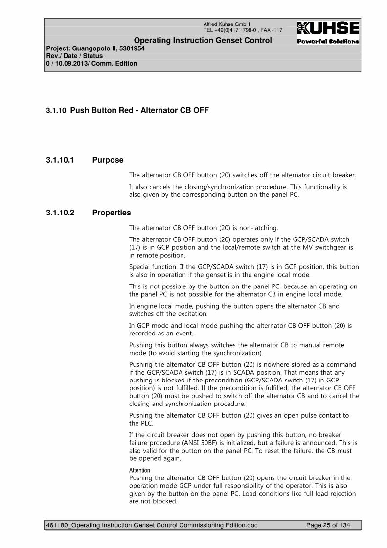
3.1.10.1 Purpose
%� �� �������A�<���,������&��'��/���� ���**��� �� ��������������,� 0 ���
4�������� ���� ������#9�+�������1��������� ��� ��%����*���������+�������#�( ��,+��� ����� �������#�,����������� ��� �����
3.1.10.2 Properties
%� �� �������A�<���,������&��'�������������#��
%� �� �������A�<���,������&��'��� �� ����+��*��� ����9.�2�2��/�����&�7'������������������������� ���9� !�� ��/��������� �;3��/����# ��������� !�� �����������
.� ���*�������>�4*��� ����9.�2�2��/�����&�7'��������������������������,����������������� �������*��� �# �� ���������� � �#�� ����!�� ��
%����������������, �,+��� �,����������� ��� �����, ��� ����� ����#������ ��� ����������������, �*����� �� �������A���� �#�� ����!�� ��
4�� �#�� ����!�� ��������#��� �,�������� ����� �� �������A�����/���� ���**��� � )���������
4������!�� �������!�� �������#��� �� �������A�<���,������&��'����� ���� ������ ( ����
������#������,������/+���/���� ���� �� �������A����!���� !�� �!�� �&���(����������#��� ��+�������1����'��
������#��� �� �������A�<���,������&��'������/� � ����� �������!!����*��� ����9.�2�2��/�����&�7'�������.�2�2�����������%���! ��������+�������#����,��0 ���*��� ��� ����������&���9.�2�2��/�����&�7'����������������'��������*�*� ���4*��� ��� �������������*�*� ����� �� �������A�<���,������&��'�!����, ����� ������/������**��� �� �������A���������� ��� ������#�����+�������1��������� ��� ���
������#��� �� �������A�<���,������&��'�#�( ������ ����� ������������� ��6���
4*��� ���������,� 0 ���� �������� ��,+�������#������,����������,� 0 ��*��� ����� ��� �&2?.4���A�'����������1 ���,����*��� ���������� ���%����������(���*����� �,����������� ��� �����%��� � ���� �*��� ���� ��A�!����, ��� � ��#����
$���������������#��� �� �������A�<���,������&��'��� ����� ���������,� 0 ������� ��� ������!�� �������� ��*��� ������,���+��*��� ��� ������%����������#�( ��,+��� �,����������� ��� �����6���������������0 �*������ E ������� �����,��0 ����
Operating Instruction Genset Control Project: Guangopolo II, 5301954 Rev./ Date / Status 0 / 10.09.2013/ Comm. Edition
461180_Operating Instruction Genset Control Commissioning Edition.doc Page 26 of 134
Alfred Kuhse GmbH TEL +49(0)4171 798-0 , FAX -117
������2����� �� ���#�,+���!�������+����(�� ��,+��� �#�� ��������#����� ��� ������,+���� �������A��� ���#���!!����
4*��� �� ��������������,� 0 ������� � ����� �� �������A����������&� '����/���� �+�� �����#� ���**�
Operating Instruction Genset Control Project: Guangopolo II, 5301954 Rev./ Date / Status 0 / 10.09.2013/ Comm. Edition
461180_Operating Instruction Genset Control Commissioning Edition.doc Page 27 of 134
Alfred Kuhse GmbH TEL +49(0)4171 798-0 , FAX -117
�
3.2 Indications
3.2.1 Signaling Column
�������������������
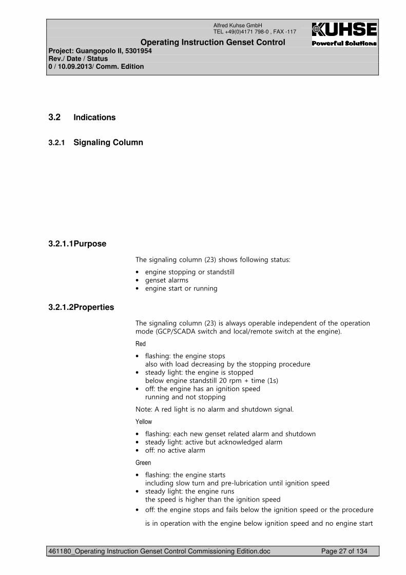
3.2.1.1 Purpose
%� ���#���#����!��&��'����/��*��/��#������>�
• �#�� ��������#�������������• �# �� ���!��• � �#�� ���������������#�
3.2.1.2 Properties
%� ���#���#����!��&��'����/+���� �, ���� � �� ����*��� ��� ������!�� �&���9.�2�2��/����������9� !�� ��/��������� � �#�� '��
���
• *����#>��� � �#�� ����������/�������� �� ���#�,+��� ��������#����� ��� �
• ��� �+��#��>��� � �#�� ��������� ��, �/� �#�� ��������������!�G���! �&��'�
• ��**>��� � �#�� �������#��������� ��������#���������������#�
?�� >�2�� ���#����������!����������/����#���
1����2
• �*����#>� ���� /�# �� ��� � ���!����������/��• ��� �+��#��>����( �,����0��/ �# ���!�• �**>�������( ��!�
)����
• �*����#>��� � �#�� ��������������#���/����������� ��,��������������#��������� ��
• ��� �+��#��>��� � �#�� ��������� ��� �������#� �������� ��#��������� ���
• ��**>��� � �#�� ����������*���, �/��� ��#��������� ������� ����� ��� �
�������� ������/������ � �#�� �, �/��#��������� �������� �#�� ������
Operating Instruction Genset Control Project: Guangopolo II, 5301954 Rev./ Date / Status 0 / 10.09.2013/ Comm. Edition
461180_Operating Instruction Genset Control Commissioning Edition.doc Page 28 of 134
Alfred Kuhse GmbH TEL +49(0)4171 798-0 , FAX -117
�
� � �+��� �� ������� �#� ���#����#��������4*�������� ��6��!+��( ��!*���������
������� �!��� ���,������&��'����� ����� ��#�����*��� ���#���#����!��&��'��%� ��#����/���#������*������ �������
������>�%�������!������������ ������� �8���&8�#�� ���������� '�����4��&� �� ��4�� �*� ��� '��%� ������������*������#���#����!���� ��� ������
%� �*����#��*���#�������, ������ ��! �*� =� ��+��������� �����#��
Operating Instruction Genset Control Project: Guangopolo II, 5301954 Rev./ Date / Status 0 / 10.09.2013/ Comm. Edition
461180_Operating Instruction Genset Control Commissioning Edition.doc Page 29 of 134
Alfred Kuhse GmbH TEL +49(0)4171 798-0 , FAX -117
�
3.2.2 LED Position Indicator – Alternator Circuit Breaker
HH.�����A2����.��������������������������������������������������
3.2.2.1 Purpose
%� �� �������A����������&� '����/���� �����������*��� �� ��������������,� 0 ������ �! ���!�(��# �&;3'��/����# ����
3.2.2.2 Properties
• ������ (����,��� �� ��������������,� 0 �������� ��&<?'�• ������ ���,��� �� ��������������,� 0 ������� � ��&<��'�• �3������((����4����� ���,������#��+�������1������
&� ��������������,� 0 �������#����� ��'��• �3������(���4����� (����,������#��� ���#��
�� =� ����*��� �� ��������������,� 0 ��• �3������(������(����,���� *�� �����������• ��335����(��6,��6��*���
�����#��� �!��� ������ �� �����#� ��68����*��� �� �������A����������&� '�� ����*������ �������
Operating Instruction Genset Control Project: Guangopolo II, 5301954 Rev./ Date / Status 0 / 10.09.2013/ Comm. Edition
461180_Operating Instruction Genset Control Commissioning Edition.doc Page 30 of 134
Alfred Kuhse GmbH TEL +49(0)4171 798-0 , FAX -117
�
3.2.3 LED Position Indicator – Alternator Earthing Switch
HH.�����A2����.��������������������������������������������������
3.2.3.1 Purpose
%� �� ������ �����#��/��������������&�5'����/���� �����������*��� �� ������ �����#��/��������� �! ���!�(��# �&;3'��/����# ����
3.2.3.2 Properties
• ������ (����,��� �� ������ �����#��/����������� ��• ������ ���,��� �� ������ �����#��/���������� � ��• �3������(������(����,���� *�� �����������
�����#��� �!��� ������ �� �����#� ��68����*��� �� ������ �����#��/��������������&�5'�� ����*������ �������
%� �� ������ �����#��/����������+�, ���� ����*��� �� ��������������,� 0 ������� � ���.���� �� �������A����������&� '����� ���4��������,��0 ��,+��� ���0��#��� �������/�����/��, �� � ���*��� � �������(��# ��� � ������� �� �������
%� �� ������ �����#��/����������+�, ��/���� ��!��+����� �;3��/����# ���
%� �� ������ �����#��/�����������, ���� ��*����* �+�� ����������#�!��� ��� �/��0����� �;3��/����# ���
Operating Instruction Genset Control Project: Guangopolo II, 5301954 Rev./ Date / Status 0 / 10.09.2013/ Comm. Edition
461180_Operating Instruction Genset Control Commissioning Edition.doc Page 31 of 134
Alfred Kuhse GmbH TEL +49(0)4171 798-0 , FAX -117
�������4*��� �� ������ �����#��/����������� ����� � �#�� ���������,��0 ��

Operating Instruction Genset Control Project: Guangopolo II, 5301954 Rev./ Date / Status 0 / 10.09.2013/ Comm. Edition
461180_Operating Instruction Genset Control Commissioning Edition.doc Page 32 of 134
Alfred Kuhse GmbH TEL +49(0)4171 798-0 , FAX -117
�
3.2.4 LED Position Indicator – Alternator Neutral Earthing Switch
HH.�����A2:���.��������������������������������������������������
3.2.4.1 Purpose
%� �� ������� ���� �����#��/��������������&��'����/���� �����������*��� �� ������� ���� �����#��/�������
3.2.4.2 Properties
• ������ (����,��� �� ������� ���� �����#��/����������� ��• ������ ���,��� �� ������� ���� �����#��/���������� � ��• �������(����3������(,���� *�� �����������
�� �����+��#������� �!��� ������ �� �����#� ��68����*��� �� ������� ���� �����#��/��������������&��'�� ����*������ �������
� � ����#������ �0�����*� �#�� �������$�� �������� ����� �� ������� �;3�,��,���������� �� ���� �����#��/����# ���
����;3�,��,���� �� ���� �����#�� ���������������� � ���<� �� ���� �����#��/�����������, ���� ������� �� ��������;�� ������� ��������� ���������/ ��*������!��� �������
����!�� ���*��!������*��� �� ������� ���� �����#��/���� ���� ��� �����!����
������4�����!����!�� ���� �� ���� �����#��/����������� ����# �� ��/������ �

Operating Instruction Genset Control Project: Guangopolo II, 5301954 Rev./ Date / Status 0 / 10.09.2013/ Comm. Edition
461180_Operating Instruction Genset Control Commissioning Edition.doc Page 33 of 134
Alfred Kuhse GmbH TEL +49(0)4171 798-0 , FAX -117
� ��������������,� 0 ������� �� ����������� ���+������ �*������� ��/������������ �� ������� �;3�,��,������� �� )������� �� =� �� ���
Operating Instruction Genset Control Project: Guangopolo II, 5301954 Rev./ Date / Status 0 / 10.09.2013/ Comm. Edition
461180_Operating Instruction Genset Control Commissioning Edition.doc Page 34 of 134
Alfred Kuhse GmbH TEL +49(0)4171 798-0 , FAX -117
�
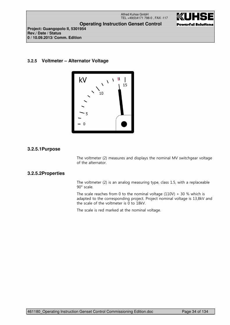
3.2.5 Voltmeter – Alternator Voltage
�
����
3.2.5.1 Purpose
%� �(��! � ��&�'�! ��� ���������+���� ���!���;3��/����# ��(��# ��*��� �� �������
3.2.5.2 Properties
%� �(��! � ��&�'��������#�! �����#��+� �����������/������ �� , ���I��� ��
%� ��� �� �� ��*��!�������� ���!���(��# �&���3'�G����F�/����������� ������� ����� �������#����E �������E �����!���(��# ������� 03������ ��� ��*��� �(��! � ����������� 03���
%� ��� ����� ��!�0 ������ ���!���(��# ��
Operating Instruction Genset Control Project: Guangopolo II, 5301954 Rev./ Date / Status 0 / 10.09.2013/ Comm. Edition
461180_Operating Instruction Genset Control Commissioning Edition.doc Page 35 of 134
Alfred Kuhse GmbH TEL +49(0)4171 798-0 , FAX -117
3.2.6 Ammeter – Alternator Current
������������������������
3.2.6.1 Purpose
%� �!! � ��&�'�! ��� ���������+���� �� ���������� ���&6�'��
3.2.6.2 Properties
%� �!! � ��&�'���������������#�! �����#��+� �/������ �� , ���I��� ��
%� ��� �� �� ��*��!�������� ���!����%�����#���������#������ ����� �������#����E ���� �#������9�2�/������ )� ���#���!�����# ��)�%�����#��
%� ��� ����� ��!�0 ������ ���!������� ����
Operating Instruction Genset Control Project: Guangopolo II, 5301954 Rev./ Date / Status 0 / 10.09.2013/ Comm. Edition
461180_Operating Instruction Genset Control Commissioning Edition.doc Page 36 of 134
Alfred Kuhse GmbH TEL +49(0)4171 798-0 , FAX -117
�
3.2.7 Double Voltmeter – Synchronization Voltage
������������������������
3.2.7.1 Purpose
%� ����, �(��! � ��&5'���!�� ���� �,��,��(��# �&2'�/������ �� ������(��# �&A'������#��+�������1������
3.2.7.2 Properties
%� ����, �(��! � ��&5'��������#���������#�� (�� �����������
%� ��� �� �� ��*��!��������!���(��# �&���3'�G���F��/��������, ����� ������� ����� �������#����E �������E �����!���(��# ������� 03������ ��� ��*��� �(��! � ����������� 03���
%� �(��# ��&6�96�'�� ��/���� ������� ����, �(��! � ��&5'������#��� ��+�������1��������� ���&!���������!���'��
4*�����+�������1��������� ��� ����������� ������ ����, �(��! � ��&5'��� �������� �� ��
Operating Instruction Genset Control Project: Guangopolo II, 5301954 Rev./ Date / Status 0 / 10.09.2013/ Comm. Edition
461180_Operating Instruction Genset Control Commissioning Edition.doc Page 37 of 134
Alfred Kuhse GmbH TEL +49(0)4171 798-0 , FAX -117
�
3.2.8 Double Frequency Meter – Synchronization Frequency
�
��
3.2.8.1 Purpose
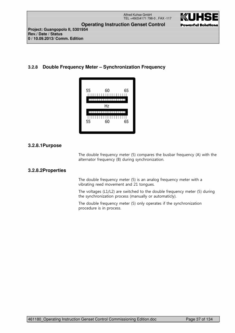
%� ����, �*� =� ��+�! � ��&�'���!�� ���� �,��,��*� =� ��+�&2'�/������ �� ������*� =� ��+�&A'������#��+�������1������
3.2.8.2 Properties
%� ����, �*� =� ��+�! � ��&�'��������#�*� =� ��+�! � ��/�����(�,����#�� ��!�( ! ������������#� ���
%� �(��# ��&6�96�'�� ��/���� ������� ����, �*� =� ��+�! � ��&�'������#��� ��+�������1��������� ���&!��+�������!���+'��
%� ����, �*� =� ��+�! � ��&�'���+��� �� ���*��� ��+�������1��������� ��� ����������� �����
Operating Instruction Genset Control Project: Guangopolo II, 5301954 Rev./ Date / Status 0 / 10.09.2013/ Comm. Edition
461180_Operating Instruction Genset Control Commissioning Edition.doc Page 38 of 134
Alfred Kuhse GmbH TEL +49(0)4171 798-0 , FAX -117
�
3.2.9 Synchronoscope
������������������������
3.2.9.1 Purpose
%� ��+����������� �&$'���!�� ���� �*� =� ��+������ ���� ��# �, �/ ��� ����������� �,��,�������#��+�������1������
3.2.9.2 Properties
%� ��+����������� �&$'������� ���� ���� ��# �,+���!��� ��68��>������J���0���� =��( ���������� ��# ��*���� #� ����
%� ��� ���*��� �68��!�( ! ��������� ����** � ���*� =� ��� ��, �/ ���� �� ����������� �,��,���
�����#����0/�� �!�( ! ������ �� ������*� =� ��+����������#��������#������ �����0/�� �!�( ! ������ �� ������*� =� ��+���������/��
%� �� =��� ����� ��# ��*���� #� ��������/��,+�����!��� ��68��������J���0����������/�������!�( ! ����
%� �(��# ��&6�96�'�� ��/���� ������� ��+����������� �&$'������#��� ��+�������1��������� ���&!���������!���'��
%� ��+����������� �&$'������������� �������*�����+�������1��������� ��� ����������� �����
Operating Instruction Genset Control Project: Guangopolo II, 5301954 Rev./ Date / Status 0 / 10.09.2013/ Comm. Edition
461180_Operating Instruction Genset Control Commissioning Edition.doc Page 39 of 134
Alfred Kuhse GmbH TEL +49(0)4171 798-0 , FAX -117
�
3.3 Units
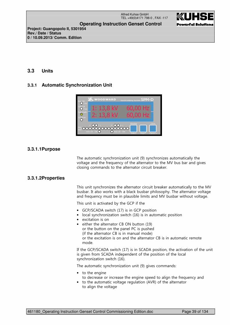
3.3.1 Automatic Synchronization Unit
�
���
3.3.1.1 Purpose
%� ����!�����+�������1����������&�'��+�������1 �����!���+��� �(��# ������ �*� =� ��+��*��� �� ����������� �;3�,���,�����#�( �������#���!!��������� �� ��������������,� 0 ���
3.3.1.2 Properties
%����������+�������1 ���� �� ��������������,� 0 �����!���+������ �;3�,��,���4�����/��0��/�����,�0�,��,����������+��%� �� ������(��# ����*� =� ��+�!����, ��������, ��!�������;3�,��,��/�������(��# ���
%���������������(� ��,+��� ������*��� ��
• ���9.�2�2��/�����&�7'��������������������• ����+�������1������/�����&�$'����������!�������������• )���������������• ��� ���� �� �������A�<?�,������&��'��
����� �,����������� ��� ����������� ���&�*��� �� �������A�������!���!�� '������� � )������������������� �� �������A����������!����� !�� �!�� ��
4*��� ����9.�2�2��/�����&�7'�������.�2�2������������� ����(������*��� ���������#�( ��*��!�.�2�2���� � �� ����*��� �����������*��� �����+�������1������/�����&�$'��
%� ����!�����+�������1����������&�'�#�( ����!!���>��
• ������ � �#�� ������ �� � �������� � ��� � �#�� ��� ������#���� �*� =� ��+����
• ������ ����!����(��# �� #������&23-'��*��� �� �����������#���� �(��# �
Operating Instruction Genset Control Project: Guangopolo II, 5301954 Rev./ Date / Status 0 / 10.09.2013/ Comm. Edition
461180_Operating Instruction Genset Control Commissioning Edition.doc Page 40 of 134
Alfred Kuhse GmbH TEL +49(0)4171 798-0 , FAX -117
4*��� ��+�������1������������ ��*�+���!� � ����� ����!�����+�������1����������&�'��/���� ���**��4*��� ��+�������1�����*������ ������/�����, �� ���(� ������� ��+�������1�����!����, ����� ��#����
%� ���� �(���������,����,+��� ��6����� ���*� ����!���� ���
Operating Instruction Genset Control Project: Guangopolo II, 5301954 Rev./ Date / Status 0 / 10.09.2013/ Comm. Edition
461180_Operating Instruction Genset Control Commissioning Edition.doc Page 41 of 134
Alfred Kuhse GmbH TEL +49(0)4171 798-0 , FAX -117
�
3.3.2 Multifunctional Monitoring Unit (MMU) – Siemens Sentron PAC3200
������������������������
3.3.2.1 Purpose
%� �;;:�& '�! ��� ���� ���������!�������� ��������! � �������� �! ���!�(��# �&;3'��/����# ����
3.3.2.2 Properties
%� �;;:�& '����(�� ���� (��� ���������(�����*�,�������� ��6����
4���� ��*�!*���������*��� �! �����#�������� ���*������( ���/ �������/ ��*�������� �;;:�& '������ ���� ���#���*����� ��������( ���/ �������/ ��*�����!�# ! ������(����1������
%� ����#�!!��#�*��������������/�������� �� ���
3.3.2.3 Operation
A+��� �*����*��������0 +���������5��� ��� ����>�
• ��(�#� ������#���� �! ����• �� ����� �! ��� ��(� �����+��• �����+���� ������ �� (�� �� ����#��
�������5�! ��>��
• �#�� >���� ���� ������ �������������� ������*��!��� �����+��*��� �� (�� �� ����#������� �����+��*��� �! ����
• �#&� >�!�( ���� �� ������,����/����• �#"� >�!�( ���� �� ������,����/�/����
• �#7� >������ �!���! ���
����� >������ �� �� ��! ��� ���+��
����� >��� ����� � ����!�� ��*��� �� (�� �� ����#
Operating Instruction Genset Control Project: Guangopolo II, 5301954 Rev./ Date / Status 0 / 10.09.2013/ Comm. Edition
461180_Operating Instruction Genset Control Commissioning Edition.doc Page 42 of 134
Alfred Kuhse GmbH TEL +49(0)4171 798-0 , FAX -117
�
%� �����+������� ��*��/��#�(� �>�
• ���( ���/ ��• � ���( ���/ ��• ��� �����/ ��• ���� ���6��• ���� ���6��• ���� ���6��• (��# �6��6��• (��# �6��6��• (��# �6��6��• ��/ ��*�����• *� =� ��+�• ���( � � �#+�• � ���( � � �#+
Operating Instruction Genset Control Project: Guangopolo II, 5301954 Rev./ Date / Status 0 / 10.09.2013/ Comm. Edition
461180_Operating Instruction Genset Control Commissioning Edition.doc Page 43 of 134
Alfred Kuhse GmbH TEL +49(0)4171 798-0 , FAX -117
�
3.4 Visualization
3.4.1 Panel PC
���
3.4.1.1 Purpose
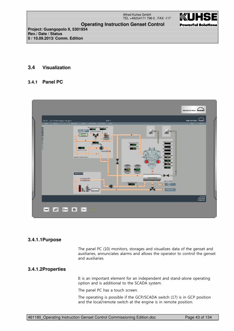
%� ��� ����&��'�!�������������# �����(����1 ������*��� �# �� ������)���� ���������� ���!������/���� ��� ����������������� �# �� ������)���� ���
3.4.1.2 Properties
4��������!������� ! ���*�������� � �� ������������� ��� ����#��������������������������� �.�2�2��+�� !���
%� ��� ����������������� ���
%� ��� ����#���������, ��*��� ����9.�2�2��/�����&�7'������������������������� ���9� !�� ��/��������� � �#�� �������� !�� �����������
Operating Instruction Genset Control Project: Guangopolo II, 5301954 Rev./ Date / Status 0 / 10.09.2013/ Comm. Edition
461180_Operating Instruction Genset Control Commissioning Edition.doc Page 44 of 134
Alfred Kuhse GmbH TEL +49(0)4171 798-0 , FAX -117
;��������#���������# �����!������������������ � �� ����*��� �����������*����9.�2�2��/�����&�7'������ ���9� !�� ��/��������� � �#�� ��
%� �� � �����������**�&�� ������������'�*��������*����� �����(����# �� ���!���������� � �� ����*��� �����������*��� ����9.�2�2��/�����&�7'��
%� ��� ����#����! ���,� ������� ��� ����&��'�/��, ��� �� ����� ��+�,+��� ��������#��+!,�������� ���� ���
%� ��������*��+!,������(� ����*��!�,������ ������>�
K� (����,� ������#����(� ��0��� � (( ��� � ��
K� ����2, *����
K� ����(�, ���� ���������
K� ���, �����������������/��� � (( ���� ��
K� (�� , ����(�, �9�������!� ��
%� �� ������ ��!��� �������� ������� �,����!��� ���
����!�� �� ������ ��� �.�2�2�����! ��������
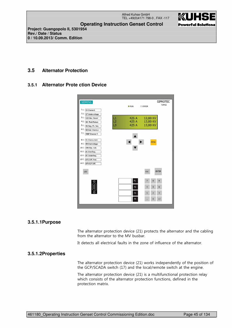
Operating Instruction Genset Control Project: Guangopolo II, 5301954 Rev./ Date / Status 0 / 10.09.2013/ Comm. Edition
461180_Operating Instruction Genset Control Commissioning Edition.doc Page 45 of 134
Alfred Kuhse GmbH TEL +49(0)4171 798-0 , FAX -117
3.5 Alternator Protection
3.5.1 Alternator Prote ction Device
�
���
3.5.1.1 Purpose
%� �� ���������� ������� (�� �&��'����� ������ �� ����������� ��,��#�*��!��� �� ����������� �;3�,��,���
4��� � ����� ������*��������� �1�� ��*���*� �� ��*��� �� �������
3.5.1.2 Properties
%� �� ���������� ������� (�� �&��'�/��0����� � �� ��+��*��� �����������*��� ����9.�2�2��/�����&�7'������ ���9� !�� ��/��������� � �#�� ��
%� �� ���������� ������� (�� �&��'�����!���*������������ ������� +�/���������������*��� �� ���������� ������*����������� *�� ������� ����� ������!���)��
Operating Instruction Genset Control Project: Guangopolo II, 5301954 Rev./ Date / Status 0 / 10.09.2013/ Comm. Edition
461180_Operating Instruction Genset Control Commissioning Edition.doc Page 46 of 134
Alfred Kuhse GmbH TEL +49(0)4171 798-0 , FAX -117
�
%� �!�����������*����� >�
• �( ����� ���9������������������� ���• � ����*���• ���** � �������� ���*���
%� ����/�� ��� +����������������� ����#�!! ��*��>�
• �� �������A������&���� �������� ����������'�• �� � )��������&����6�������'�• � �#�� �������/��&����* �+�����'�• �,� 0 ��*��� �&���,� 0 �������*����'�• �� +�/�����#�&����6�����'�• �A������&����6�������'�• �#�� �������/��&����6�������'�
����� �� ��*�����*��!����������*�,������ �*� ������ ��6��������(�� ���
2���� �*������ �, ��/����68���&2'��/����������� ��� ������������
%� �� ���������� ������� (�� �&��'���� =���� ��/�����/�����#�*��������&� +�������'���
4���� ��*����� ������� +�!*����������� >�
• � �������A�/��, ������ ���• � ������� � )��������/��, ����(� ��• ����,�� ���+�������1�����/��, ����(� ��• �#�� �/��, ��������/��• � �������A�/��, ��/���� �����!���� !�� ���
%� �68��,������&A'������� �� ��*����� �!��� �������� �� � ��*� ���� � ��*����4������ � ���+����������� �68��,������&A'����� � ���+�0�����*������, *�� ��� � �����, �#�( ��*��!�����,��������� �������.�2�2���
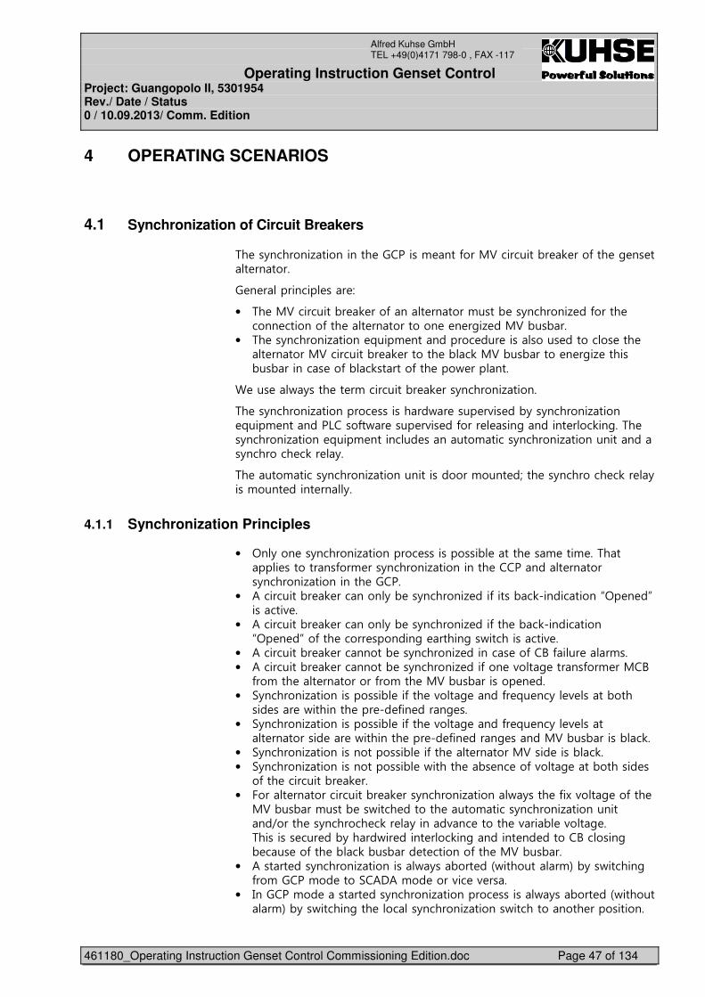
Operating Instruction Genset Control Project: Guangopolo II, 5301954 Rev./ Date / Status 0 / 10.09.2013/ Comm. Edition
461180_Operating Instruction Genset Control Commissioning Edition.doc Page 47 of 134
Alfred Kuhse GmbH TEL +49(0)4171 798-0 , FAX -117
4 OPERATING SCENARIOS
4.1 Synchronization of Circuit Breakers
%� ��+�������1���������� ��������! ���*���;3���������,� 0 ���*��� �# �� ��� �������
� � ��������� ��� >�
• �%� �;3���������,� 0 ���*���� ������!����, ��+�������1 ��*����� ����� �������*��� �� ����������� � � �#�1 ��;3�,��,���
• �%� ��+�������1����� =���! ���������� ��� ��������� �������� ��� �� ������;3���������,� 0 ������� �,�0�;3�,��,����� � �#�1 ������,��,������� ��*�,�0������*��� ���/ �������
� ��� �/+���� �� �!���������,� 0 ���+�������1������
%� ��+�������1��������� ���������/� ���� �(�� ��,+��+�������1����� =���! �������6����*�/� ���� �(�� ��*���� ���#������� ���0��#��%� ��+�������1����� =���! �������� �������!�����+�������1���������������+�������� �0�� +��
%� ����!�����+�������1������������������!���� �L��� ��+�������� �0�� +����!���� ����� ��+��
4.1.1 Synchronization Principles
• �<�+��� ��+�������1��������� �����������, ����� ��! ���! ��%������ ���������*��! ���+�������1���������� ��������� �������+�������1���������� ������
• �2���������,� 0 �������+�, ��+�������1 ���*�����,�0�����������C<� � �D�������( ��
• �2���������,� 0 �������+�, ��+�������1 ���*��� �,�0�����������C<� � �D��*��� ����� �������#� �����#��/�����������( ��
• �2���������,� 0 ��������, ��+�������1 ������� ��*��A�*��� ��!���• �2���������,� 0 ��������, ��+�������1 ���*��� �(��# �����*��! ��;�A�
*��!��� �� ���������*��!��� �;3�,��,������� � ���• �.+�������1�������������, ��*��� �(��# ����*� =� ��+� ( ����,����
��� ��� �/�������� ��� �� *�� ����# ���• �.+�������1�������������, ��*��� �(��# ����*� =� ��+� ( ����
� ��������� �� �/�������� ��� �� *�� ����# �����;3�,��,�����,�0��• �.+�������1�����������������, ��*��� �� ������;3���� ����,�0��• �.+�������1�����������������, �/������ �,� �� ��*�(��# ���,������� ��
�*��� ���������,� 0 ���• ������ ��������������,� 0 ���+�������1�����/+���� �*�)�(��# ��*��� �
;3�,��,��!����, ��/���� ������� ����!�����+�������1������������9����� ��+������� �0�� +�����(�� ������ �(��, �(��# ��%�������� ��� ��,+����/�� ����� ���0��#������� �� ������A������#�, ��� ��*��� �,�0�,��,��� � �������*��� �;3�,��,���
• �2����� ���+�������1��������/+��,��� ��&/��������!'�,+��/������#�*��!�����!�� ����.�2�2�!�� ����(�� �( ����
• �4������!�� ������ ���+�������1��������� ������/+��,��� ��&/��������!'�,+��/������#��� �����+�������1������/������������ �������������
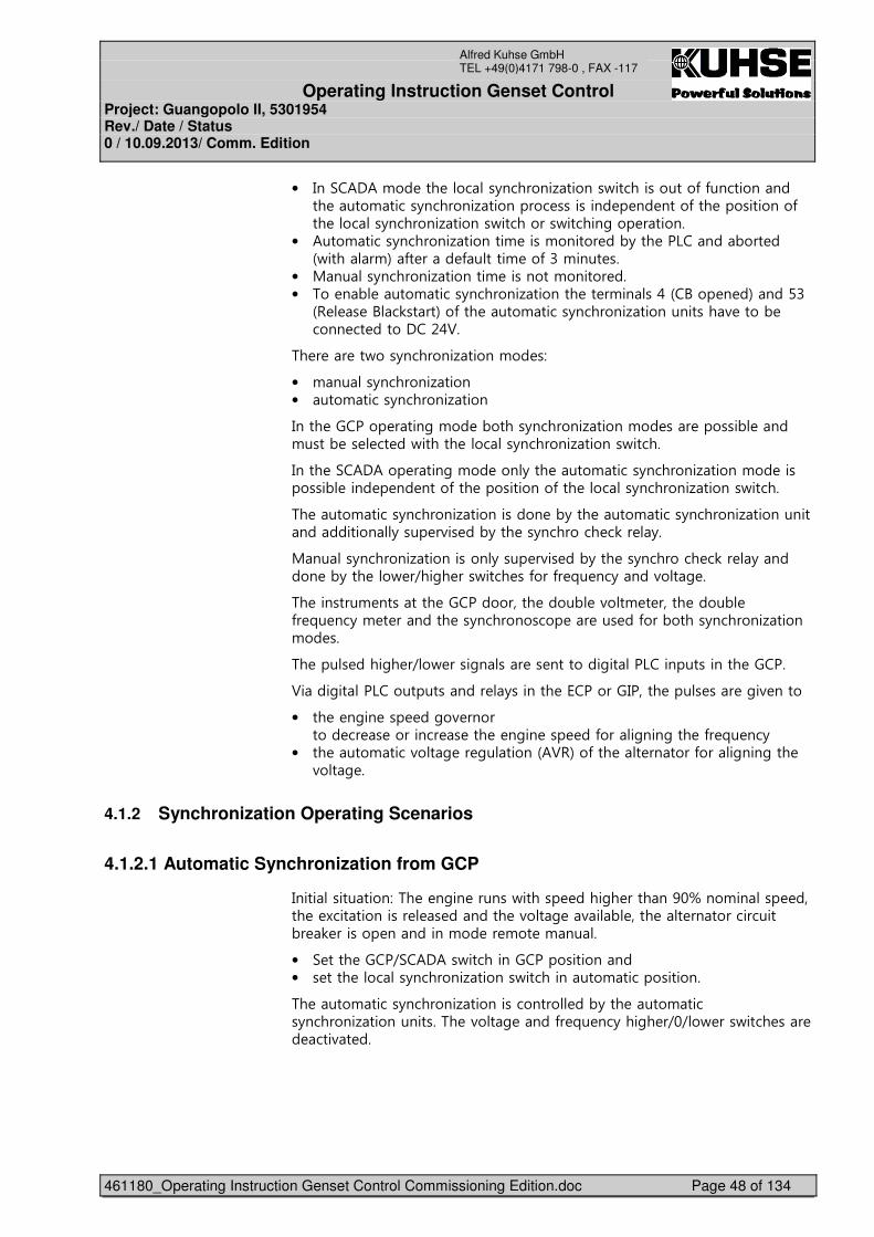
Operating Instruction Genset Control Project: Guangopolo II, 5301954 Rev./ Date / Status 0 / 10.09.2013/ Comm. Edition
461180_Operating Instruction Genset Control Commissioning Edition.doc Page 48 of 134
Alfred Kuhse GmbH TEL +49(0)4171 798-0 , FAX -117
• �4��.�2�2�!�� ��� �����+�������1������/�������������*�*������������� ����!�����+�������1��������� ��������� � �� ����*��� �����������*��� �����+�������1������/���������/������#��� �������
• �2���!�����+�������1�������! ����!������ ��,+��� ��6�����,��� ��&/�����!'�*� ���� *�����! ��*���!���� ���
• �;����+�������1�������! ��������!������ ���• �%�� �, ����!�����+�������1������� �� �!����5�&�A��� � �'�������
&- � �A�0����'��*��� ����!�����+�������1������������( ����, ����� �� ���������53��
%� � �� ��/���+�������1�����!�� �>�
• �!����+�������1�����• ����!�����+�������1�����
4���� ������� ����#�!�� �,�����+�������1�����!�� ��� ������, ����!����, �� �� ��/������ �����+�������1������/������
4���� �.�2�2��� ����#�!�� ���+��� ����!�����+�������1�����!�� ���������, ���� � �� ����*��� �����������*��� �����+�������1������/������
%� ����!�����+�������1����������� �,+��� ����!�����+�������1��������������������+���� �(�� ��,+��� ��+�������� �0�� +��
;����+�������1����������+���� �(�� ��,+��� ��+�������� �0�� +������� �,+��� ��/ �9��#� ���/���� ��*���*� =� ��+����(��# ��
%� �������! �������� ������������� ����, �(��! � ����� ����, �*� =� ��+�! � ������� ��+����������� �� ��� ��*���,�����+�������1�����!�� ���
%� ���� ����#� �9�/ ����#���� �� ��������#����6�������������� ������
3����#����6�������������� +������� �8�������4����� ���� ��� �#�( �����
• ��� � �#�� ��� ��#�( ���������� �� � �������� � ��� � �#�� ��� ��*����#���#��� �*� =� ��+�
• ��� ����!����(��# �� #������&23-'��*��� �� ������*����#���#��� �(��# ��
4.1.2 Synchronization Operating Scenarios
4.1.2.1 Automatic Synchronization from GCP
4�������������>�%� � �#�� ������/������ ����#� ��������F���!����� ����� � )������������ � ������� �(��# �(�, ���� �� ��������������,� 0 ������� ��������!�� �� !�� �!����
• �. ���� ����9.�2�2��/�������������������������• �� ���� �����+�������1������/�����������!��������������
%� ����!�����+�������1�������������� ��,+��� ����!�����+�������1������������%� �(��# ����*� =� ��+���#� �9�9�/ ���/���� ��� �� ���(� ���
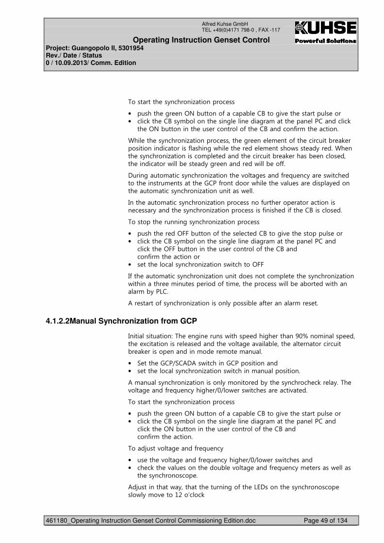
Operating Instruction Genset Control Project: Guangopolo II, 5301954 Rev./ Date / Status 0 / 10.09.2013/ Comm. Edition
461180_Operating Instruction Genset Control Commissioning Edition.doc Page 49 of 134
Alfred Kuhse GmbH TEL +49(0)4171 798-0 , FAX -117
�
%��������� ��+�������1��������� ���
• �������� �#� ��<?�,�������*����, ��A����#�( ��� ��������� �����• ����0��� ��A��+!,������� ����# ��� ���#�!����� ��� ����������0�
�� �<?�,����������� ��� ����������*��� ��A�������*��!��� ��������
��� ��� ��+�������1��������� ������ �#� �� ! ����*��� ���������,� 0 �����������������������*����#�/�� ��� �� �� ! ������/���� �+�� ����� ���� ��+�������1����������!� � ������� ���������,� 0 �����, ����� ����� ����������/��, ��� �+�#� ������ ��/��, ��**��
�����#����!�����+�������1������� �(��# �����*� =� ��+�� ��/���� ������� �������! �������� �����*����������/�� ��� �(� ��� �����+ ������� ����!�����+�������1������������/ ��
4���� ����!�����+�������1��������� ������*���� ���� ��������������� � ���+������ ��+�������1��������� ������*����� ���*��� ��A������� ���
%��������� �������#��+�������1��������� ���
• �������� �� ��<���,�������*��� �� �� ���A����#�( ��� ��������� �����• ����0��� ��A��+!,������� ����# ��� ���#�!����� ��� ��������
���0��� �<���,����������� ��� ����������*��� ��A��������*��!��� ����������
• �� ���� �����+�������1������/��������<���
4*��� ����!�����+�������1������������ ��������!� � ��� ��+�������1�����/���������� �!���� ��� ������*���! ���� ����� ���/��, �,��� ��/�������!�,+��6���
2�� ������*��+�������1����������+������, �*� �����!�� � ���
4.1.2.2 Manual Synchronization from GCP
4�������������>�%� � �#�� ������/������ ����#� ��������F���!����� ����� � )������������ � ������� �(��# �(�, ���� �� ��������������,� 0 ������� ��������!�� �� !�� �!����
• �. ���� ����9.�2�2��/�������������������������• �� ���� �����+�������1������/��������!�������������
2�!����+�������1����������+�!������ ��,+��� ��+������� �0�� +��%� �(��# ����*� =� ��+���#� �9�9�/ ���/���� ��� ����(� ���
%��������� ��+�������1��������� ����
• �������� �#� ��<?�,�������*����, ��A����#�( ��� ��������� �����• ����0��� ��A��+!,������� ����# ��� ���#�!����� ��� ��������
���0��� �<?�,����������� ��� ����������*��� ��A��������*��!��� ��������
%���E����(��# ����*� =� ��+�
• ��� ��� �(��# ����*� =� ��+���#� �9�9�/ ���/���� ������• ��� �0��� �(� ������� ����, �(��# ����*� =� ��+�! � �����/ ���
�� ��+����������� ���
2�E�����������/+�������� �������#��*��� �68�������� ��+����������� ���/+�!�( ��������B���0�
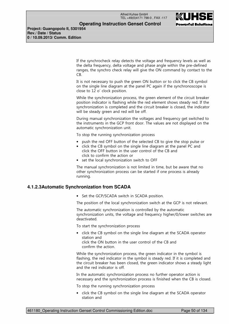
Operating Instruction Genset Control Project: Guangopolo II, 5301954 Rev./ Date / Status 0 / 10.09.2013/ Comm. Edition
461180_Operating Instruction Genset Control Commissioning Edition.doc Page 50 of 134
Alfred Kuhse GmbH TEL +49(0)4171 798-0 , FAX -117
�
4*��� ��+������� �0�� +�� � ������ �(��# ����*� =� ��+� ( ����/ ����� �� ��*� =� ��+��� ��(��# ������� ��# �/�������� ��� �� *�� ����# ����� ��+�������� �0�� +�/��#�( ��� �<?���!!���,+������������� ��A���
4���������� � ���+����������� �#� ��<?�,���������������0��� ��A��+!,������� ����# ��� ���#�!����� ��� ����#����*��� ��+����������� ������� ��������B����0�����������
��� ��� ��+�������1��������� ������ �#� �� ! ����*��� ���������,� 0 �����������������������*����#�/�� ��� �� �� ! ������/���� �+�� ���4*��� ��+�������1����������!� � ������� ���������,� 0 �������� ����� ����������/��, ��� �+�#� ������ ��/��, ��**��
�����#�!����+�������1������� �(��# �����*� =� ��+�# ���/���� ������� �������! ��������� �����*�����������%� �(� ��� ���������+ ������� ����!�����+�������1�����������
%��������� �������#��+�������1��������� ���
• �������� �� ��<���,�������*��� �� �� ���A����#�( ��� ��������� �����• ����0��� ��A��+!,������� ����# ��� ���#�!����� ��� ��������
���0��� �<���,����������� ��� ����������*��� ��A��������0�������*��!��� ����������
• �� ���� �����+�������1������/��������<���
%� �!����+�������1�������������!�� �������! ��,���, �/� ����������� ���+�������1��������� ������, ����� ���*��� ����� ������� �+�������#��
4.1.2.3 Automatic Synchronization from SCADA
• �. ���� ����9.�2�2��/��������.�2�2�����������
%� �����������*��� �����+�������1������/��������� ������������� (����
%� ����!�����+�������1�������������� ��,+��� ����!�����+�������1�������������� �(��# ����*� =� ��+���#� �9�9�/ ���/���� ��� �� ���(� ���
%��������� ��+�������1��������� ���
• ����0��� ��A��+!,������� ����# ��� ���#�!����� �.�2�2��� �������������������0��� �<?�,����������� ��� ����������*��� ��A��������*��!��� ��������
��� ��� ��+�������1��������� ������ �#� ���������������� ��+!,�����*����#���� �� ���������������� ��+!,������� �+�� ���4*���������!� � ������� ���������,� 0 �����, ����� ����� �#� ��������������/����� �+��#�������� �� ���������������**��
4���� ����!�����+�������1��������� ������*���� ���� ��������������� � ���+������ ��+�������1��������� ������*����� ��/� ���� ��A������� ��� �
%��������� �������#��+�������1��������� ���
• ����0��� ��A��+!,������� ����# ��� ���#�!����� �.�2�2��� ����������������
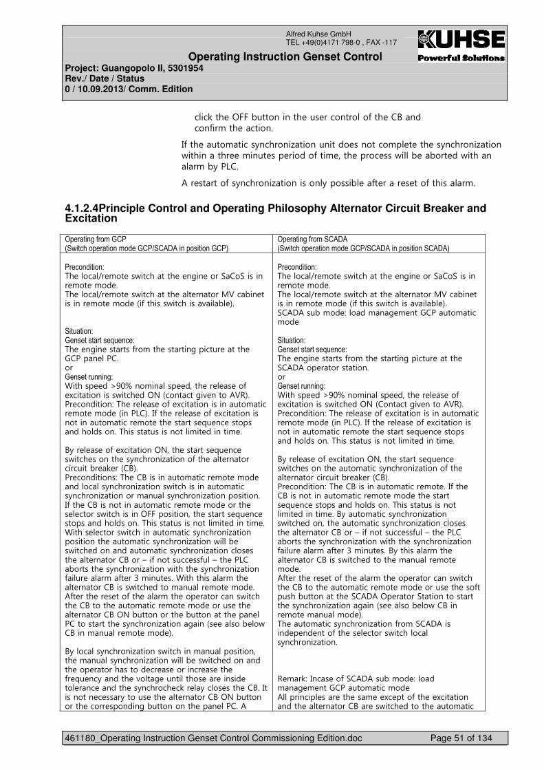
Operating Instruction Genset Control Project: Guangopolo II, 5301954 Rev./ Date / Status 0 / 10.09.2013/ Comm. Edition
461180_Operating Instruction Genset Control Commissioning Edition.doc Page 51 of 134
Alfred Kuhse GmbH TEL +49(0)4171 798-0 , FAX -117
���0��� �<���,����������� ��� ����������*��� ��A��������*��!��� ��������
4*��� ����!�����+�������1������������ ��������!� � ��� ��+�������1�����/���������� �!���� ��� ������*���! ���� ����� ���/��, �,��� ��/�������!�,+��6���
2�� ������*��+�������1����������+������, �*� ���� � ���*�������!��
4.1.2.4 Principle Control and Operating Philosophy Alternator Circuit Breaker and Excitation
+0������(3���)�*5�2�����0�����������)�*���$�$��0�������)�*6
+0������(3�����$�$5�2�����0�����������)�*���$�$��0���������$�$6
�*�����������,%� ���9� !�� ��/��������� � �#�� ����.��.�������� !�� �!�� ��%� ���9� !�� ��/��������� �� ������;3��,�� ��������� !�� �!�� �&�*�������/��������(�, '�������������,)������������8�����,%� � �#�� �������*��!��� �������#������� ����� ������� ���������)�����������(,������� ��M��F���!����� ����� �� � ��*� )������������/���� ��<?�&�������#�( �����23-'���� ���������>�%� �� � ��*� )�����������������!����� !�� �!�� �&����6�'��4*��� �� � ��*� )���������������������!����� !�� ��� ������� =� �� �������������������%������������������!�� �������! ���A+�� � ��*� )��������<?���� ������� =� �� ��/���� ������� ��+�������1������*��� �� ��������������,� 0 ��&�A'����� ����������>�%� ��A����������!����� !�� �!�� ��������+�������1������/��������������!�����+�������1��������!����+�������1���������������4*��� ��A��������������!����� !�� �!�� ������ �� ������/�����������<��������������� ������� =� �� �������������������%������������������!�� �������! �������� ������/�����������!�����+�������1���������������� ����!�����+�������1�����/��, ��/���� �����������!�����+�������1�������� ���� �� �������A����N��*��������� ��*��N��� ��6��,������� ��+�������1�����/������ ��+�������1�����*��� ��!�*� ����!���� ��������������!��� �� �������A�����/���� �����!���� !�� �!�� ��2*� ���� �� � ���*��� ��!��� ��� ���������/������� ��A������ ����!����� !�� �!�� ������ ��� �� �������A�<?�,����������� �,���������� ��� �������������� ��+�������1�����#���&� ����, �/��A����!���� !�� �!�� '���A+�����+�������1������/��������!��������������� �!����+�������1�����/��, ��/���� ���������� ��� ������������ �� � �������� � ��� �*� =� ��+������ �(��# ���������� �� ������ ��� ��� ������ ��+������� �0�� +���� ���� ��A��4���������� � ���+������ ��� �� �������A�<?�,����������� ����� �������#�,����������� ��� �����2�
�*�����������,%� ���9� !�� ��/��������� � �#�� ����.��.�������� !�� �!�� ��%� ���9� !�� ��/��������� �� ������;3��,�� ��������� !�� �!�� �&�*�������/��������(�, '��.�2�2���,�!�� >����!�# ! ����������!����!�� �����������,)������������8�����,%� � �#�� �������*��!��� �������#������� ����� �.�2�2��� �����������������)�����������(,������� ��M��F���!����� ����� �� � ��*� )������������/���� ��<?�&�������#�( �����23-'���� ���������>�%� �� � ��*� )�����������������!����� !�� �!�� �&����6�'��4*��� �� � ��*� )���������������������!����� !�� ��� ������� =� �� �������������������%������������������!�� �������! ���A+�� � ��*� )��������<?���� ������� =� �� ��/���� ������� ����!�����+�������1������*��� �� ��������������,� 0 ��&�A'����� ���������>�%� ��A����������!����� !�� ��4*��� ��A��������������!����� !�� �!�� ��� ������� =� �� �������������������%������������������!�� �������! ��A+����!�����+�������1������/���� �������� ����!�����+�������1�������� ���� �� �������A����N��*��������� ��*��N��� ��6��,������� ��+�������1�����/������ ��+�������1�����*��� ��!�*� ����!���� ���A+�������!��� �� �������A�����/���� ������� �!���� !�� �!�� ��2*� ���� �� � ���*��� ��!��� ��� ���������/������� ��A������ ����!����� !�� �!�� ������ ��� ���*�������,���������� �.�2�2�<� �����.���������������� ��+�������1�����#���&� ����, �/��A����� !�� �!���!�� '��%� ����!�����+�������1�����*��!�.�2�2������� � �� ����*��� �� ������/���������+�������1���������- !�0>�4��� ��*�.�2�2���,�!�� >����!�# ! ����������!����!�� �2�������� ��� ��� ��! � )� ����*��� � )������������� �� �������A�� ��/���� ������� ����!����
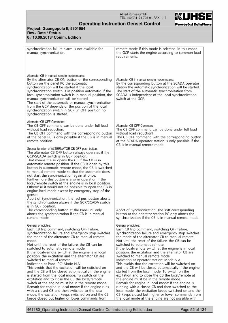
Operating Instruction Genset Control Project: Guangopolo II, 5301954 Rev./ Date / Status 0 / 10.09.2013/ Comm. Edition
461180_Operating Instruction Genset Control Commissioning Edition.doc Page 52 of 134
Alfred Kuhse GmbH TEL +49(0)4171 798-0 , FAX -117
�+�������1�����*��� ��!��������(�, �*���!����+�������1�����������$����������9�����������������������,A+��� �� �������A�<?�,����������� ����� �������#�,����������� ��� ������ ����!�����+�������1�����/��, ����� ���*��� �����+�������1������/�����������������������!�����4*��� �����+�������1������/�����������!��������������� �!����+�������1�����/��, ����� ���%� �������*��� ����!�������!����+�������1�����*��!��� ������ � �����*��� �����������*��� �����+�������1������/�������������4��<����������������+�������1������������ ����$����������9+##�������,%� ��A�<�����!!������, ���� ���� ��*�����/����������� ���������%� ��A�<�����!!���/������ ����� �������#�,���������� ��� ���������+������, ��*��� ��A�������!���� !�� �������������0�����3��������3$-%��:$%+��9+##0���;�����,%� �� �������A�<���,������/+���� �� ���*��� ����9.�2�2��/�������������������������%���! ����������� ����� ��A��*��� ��A����������!����� !�� �����������4*��� ��A������ ��,+������,������������!����� !�� �!�� ���� ��A�����/���� �����!���� !�� �!�� ���������� ����!������ ������������� ��+�������1�����#�������� ������� �!�� ������,����������������� �������*��� ���9� !�� ��/��������� � �#�� ��������������������<�� �/�� ����/��������, ������, ������ ���� ��A���� �#�� ����!�� � )� ���,+� ! �# ��+�������*��� �# �� ���2,�����*�.+�������1����>��� �� ������,������,������� ��+�������1�����/+���*��� ����9.�2�2��/�������������������������%� ����� �������#�,���������� ��� ������+�,������� ��+�������1������*��� ��A�������!���� !�� �!�� ���)������0�����0���,8����A��������!!�����/������#�<���*��� ���+�������1�����*��� ���� ! �# ��+�������/���� ���� �!�� ��*��� �� �������A����!���� !�� �!�� ��?���������� �� � ���*��� �*��� ���� ��A����, ��/���� ��������!����� !�� �!�� ��4*��� ���9� !�� ��/��������� � �#�� ���������������������� � )������������� �� �������A�� ��/���� �����!���� !�� ���4������������� ���>�;�� �?�2��%����(����������� � )��������/��, ��/���� ���������� ��A�/��, ���� �����!���+��*��� � �#�� �������� ��*��!��� ����!�� ��%���/���������� � )����������������� ��� ��A��� ���9� !�� ��/��������� � �#�� �!����, ������ �� !�� �!�� ��- !�0�*��� �#�� �������!�� >�4*��� � �#�� ������/�������� ���A������ ���/���� ������� ����!�� ���� � )��������0 ����/���� ���������� ��A�0 ������ ��,�����#� ������/ ����!!����*��!�
� !�� �!�� ��*������!�� ����� �� ���4�������!�� ��� ������������� � �#�� ��������#������!!������� =��� ! ����������$����������9�����������������������,A+��� ����� �������#�,���������� �.�2�2��� �������������� ����!�����+�������1�����/��, ����� ���%� �������*��� ����!�����+�������1�����*��!�.�2�2������� � �� ����*��� �����+�������1������/��������� ������������$����������9+##�������,%� ��A�<�����!!������, ���� ���� ��*�����/����������� �������O�%� ��A�<�����!!���/������ ����� �������#�,���������� �.�2�2��� �����������������+������, ��*��� ��A�������!���� !�� �!�� ������������������2,�����*�.+�������1����>�%� ���*������ �������#�,���������� ��� �����������������+�,������� ��+�������1������*��� ��A�������!���� !�� �!�� ���)������0�����0���,8����A��������!!�����/������#�<���*��� ���+�������1�����*��� ���� ! �# ��+�������/���� ���� �!�� ��*��� �� �������A����!���� !�� ��?���������� �� � ���*��� �*��� ���� ��A����, ��/���� ��������!����� !�� ��4*��� ���9� !�� ��/��������� � �#�� ���������������������� � )������������� �� �������A�� ��/���� �����!���� !�� �!�� ��4������������� �����������>�;�� �?�2��%����(����������� � )��������/��, ��/���� ���������� ��A�/��, ���� �����!���+��*��� � �#�� ����� ��*��!��� ����!�� ��%���/���������� � )����������������� ��� ��A��� ���9� !�� ����� � �#�� �!����, ������ �� !�� �!�� ��- !�0�*��� �#�� �������!�� >�4*��� � �#�� ����������#�/�������� ���A������ ���/���� ������� ����!�� ���� � )��������0 ����/���� ���������� ��A�0 ������ ��,�����#� ������/ ����!!����*��!��� ����!�� ����� � �#�� �� ����������, �/����
Operating Instruction Genset Control Project: Guangopolo II, 5301954 Rev./ Date / Status 0 / 10.09.2013/ Comm. Edition
461180_Operating Instruction Genset Control Commissioning Edition.doc Page 53 of 134
Alfred Kuhse GmbH TEL +49(0)4171 798-0 , FAX -117
�� ����!�� ����� � �#�� �� ����������, �/������� ���A��4�������� ����!����������� �>� �#�� ��������� ������/����� �������A���� ���
��� ���A��4�������� ����!����������� �>�8�#�� ��������� ������/����� �������A���� ���
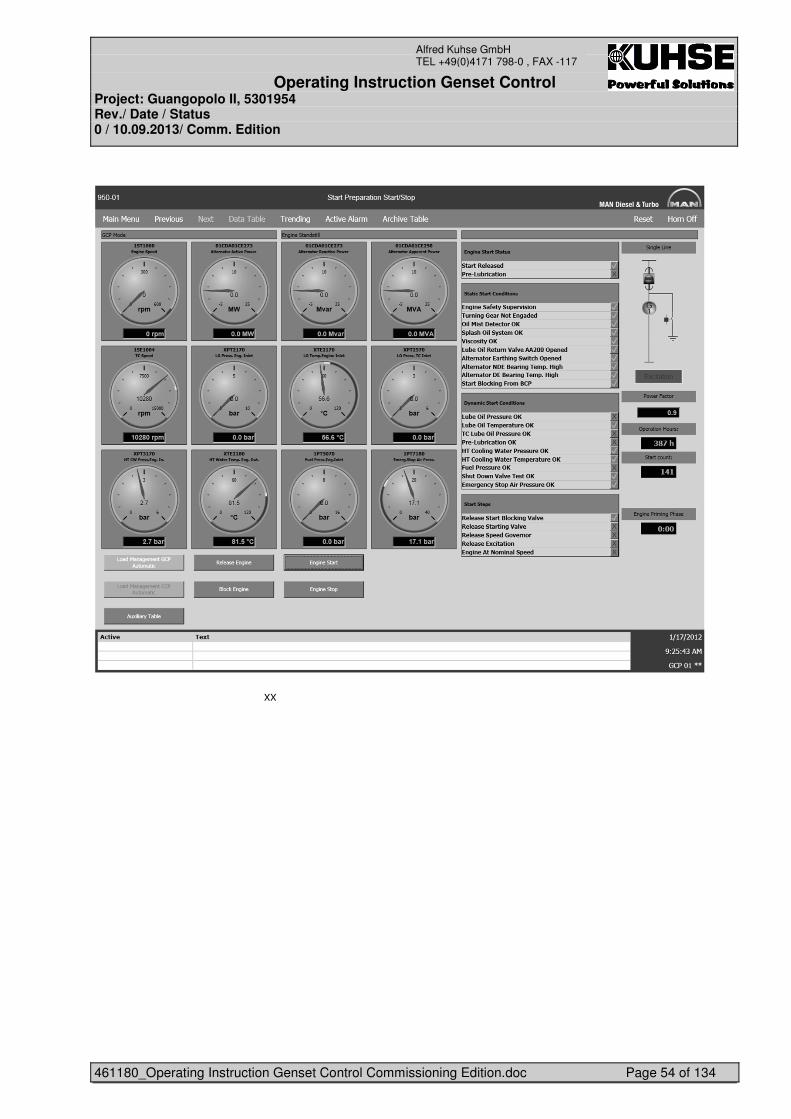
Operating Instruction Genset Control Project: Guangopolo II, 5301954 Rev./ Date / Status 0 / 10.09.2013/ Comm. Edition
461180_Operating Instruction Genset Control Commissioning Edition.doc Page 54 of 134
Alfred Kuhse GmbH TEL +49(0)4171 798-0 , FAX -117
�
�������������������������������������������������������������
))�
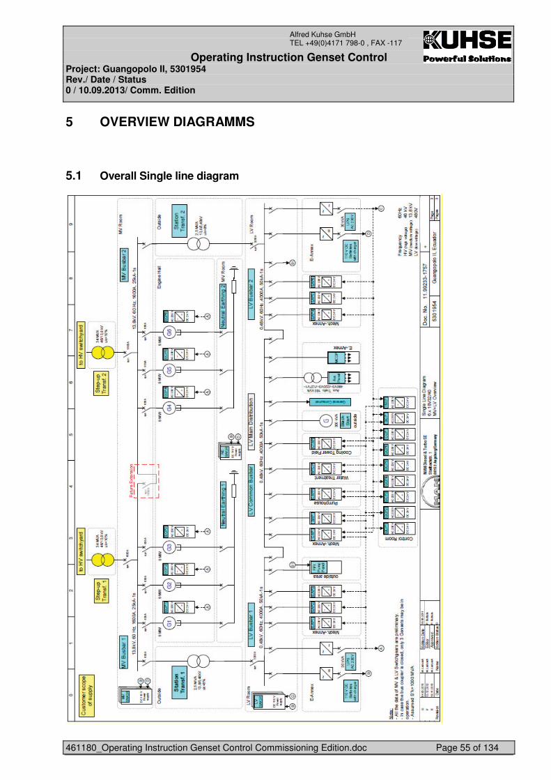
Operating Instruction Genset Control Project: Guangopolo II, 5301954 Rev./ Date / Status 0 / 10.09.2013/ Comm. Edition
461180_Operating Instruction Genset Control Commissioning Edition.doc Page 55 of 134
Alfred Kuhse GmbH TEL +49(0)4171 798-0 , FAX -117
5 OVERVIEW DIAGRAMMS
5.1 Overall Single line diagram
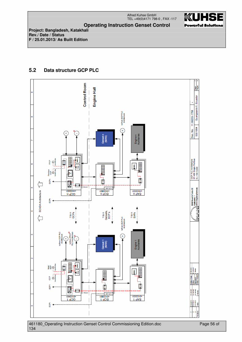
Operating Instruction Genset Control Project: Bangladesh, Katakhali Rev./ Date / Status F / 25.01.2013/ As Built Edition
461180_Operating Instruction Genset Control Commissioning Edition.doc Page 56 of 134
Alfred Kuhse GmbH TEL +49(0)4171 798-0 , FAX -117
5.2 Data structure GCP PLC
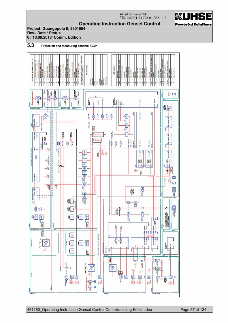
Operating Instruction Genset Control Project: Guangopolo II, 5301954 Rev./ Date / Status 0 / 10.09.2013/ Comm. Edition
461180_Operating Instruction Genset Control Commissioning Edition.doc Page 57 of 134
Alfred Kuhse GmbH TEL +49(0)4171 798-0 , FAX -117
5.3 Protecion and measuring scheme GCP
Operating Instruction Genset Control Project: Guangopolo II, 5301954 Rev./ Date / Status 0 / 10.09.2013/ Comm. Edition
461180_Operating Instruction Genset Control Commissioning Edition.doc Page 58 of 134
Alfred Kuhse GmbH TEL +49(0)4171 798-0 , FAX -117
5.4 Power Plant Operation modes
• Grid voltage and frequency variation on the busbar shall not exceed normal +/- 5%. • Manual start order for each / of all gen.-sets. • Automatic synchronizing of alternators, mains feeder will synchronize by costumer. • Parallel operation of Power Plant with grid, with adjustable values of active and reactive
Load for each gen.-set. • In the event of grid failure during grid parallel operation, decoupling from the grid within an
extremely short time for safe operation of the power plant.
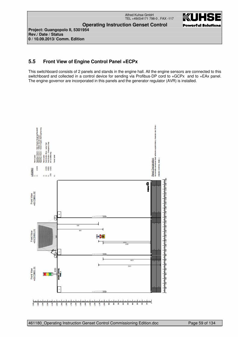
Operating Instruction Genset Control Project: Guangopolo II, 5301954 Rev./ Date / Status 0 / 10.09.2013/ Comm. Edition
461180_Operating Instruction Genset Control Commissioning Edition.doc Page 59 of 134
Alfred Kuhse GmbH TEL +49(0)4171 798-0 , FAX -117
5.5 Front View of Engine Control Panel +ECPx
This switchboard consists of 2 panels and stands in the engine hall. All the engine sensors are connected to this switchboard and collected in a control device for sending via Profibus-DP cord to +GCPx and to +EAx panel. The engine governor are incorporated in this panels and the generator regulator (AVR) is installed.
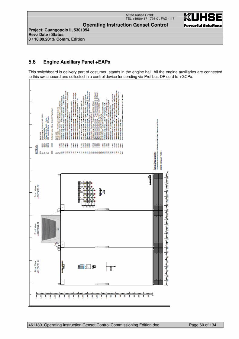
Operating Instruction Genset Control Project: Guangopolo II, 5301954 Rev./ Date / Status 0 / 10.09.2013/ Comm. Edition
461180_Operating Instruction Genset Control Commissioning Edition.doc Page 60 of 134
Alfred Kuhse GmbH TEL +49(0)4171 798-0 , FAX -117
5.6 Engine Auxiliary Panel +EAPx
This switchboard is delivery part of costumer, stands in the engine hall. All the engine auxiliaries are connected to this switchboard and collected in a control device for sending via Profibus-DP cord to +GCPx.
Operating Instruction Genset Control Project: Guangopolo II, 5301954 Rev./ Date / Status 0 / 10.09.2013/ Comm. Edition
461180_Operating Instruction Genset Control Commissioning Edition.doc Page 61 of 134
Alfred Kuhse GmbH TEL +49(0)4171 798-0 , FAX -117
6 ENGINE CONTROL FUNCTIONS
6.1 Push button of engine control at PC touch panel
• Blocking engine start • Release engine start • Start engine • Stop engine Push button Blocking engine start: By pressing this push button is the engine start blocked, no engine start is possible. It is active in all modes (GCP, SCADA or Local mode). Push button Release engine start: By pressing this push button is the engine released for remote or local start depending of selected operation mode GCP, SCADA or Local (at engine) Push button Start engine: This push button is released if the push button Release engine start is activated, operation mode GCP is selected and the local switch at engine is in remote position. By pressing the engine will start automatically at first the start conditions are requested and if they are fulfilled, pressing again causes the engine to be started. Push button Stop engine: This push button is released in operation mode GCP and the local switch at engine is in remote position. By pressing this push button the engine stopped automatically. Function of selector switch 66S6 operation mode: In position GCP, the genset can be requested using the “Manual Start/Stop” button from the PC677B and the gen. CB contol push buttons on/off at the mimic diagram is relesed. In position SCADA, the genset can be requested from the DCS system.
6.2 Start procedure of engine in GCP mode
By pressing the "Start" button the start conditions are requested. The auxiliary drives for the start requirements are requested at the same time. The following auxiliary drives are switched on: (local mode), 1. Pre-lubrication oil pump X0MJV21AP030 (P007) 2. Release speed controller 3. Request fuel module 4. Test shut down valve X-1SZV 1012
Operating Instruction Genset Control Project: Guangopolo II, 5301954 Rev./ Date / Status 0 / 10.09.2013/ Comm. Edition
461180_Operating Instruction Genset Control Commissioning Edition.doc Page 62 of 134
Alfred Kuhse GmbH TEL +49(0)4171 798-0 , FAX -117
The following conditions must be met for start release: Prelubrication time of T = 1 minute expired. (Exception: Start prelubrication is not necessary, if the standstill time is less than the adjustable time (Max. standstill time start prelubrication is required). No shutdown fault active. The turning gear not engaged. (FE46) X-1PSH2170 lube oil pressure engine start release (0,3bar) dyn. X-1PSH3170 cooling water pressure high (2bar), dyn. No X-1SZV1012 emergency stop valve fault (FE102) No Slow turn fault, purging necessary (FE148) If the start-up conditions are met, this is displayed by the LED START RELEASE . If the start conditions are fulfilled, pressing again causes the engine to be started. The engine can be shut down by pressing STOP. The start-up air valve (X-1SSV1011) is opened. If the diesel engine does not attain the ignition speed, or START is not activated, the starter valve is closed. If the diesel engine does attain the ignition speed, the LED START CONTROL go out and the following auxiliary drives are selected:
1. Cylinder lubrication 1EM2470 cylinder lub. oil pump)
Once the engine is run-up, the excitation must be switched on manually. When the nominal voltage and frequency are reached and the waiting time for load release has expired, the generator protection circuit breaker can be switched on. In order to do this, press the push button GENERATOR ON (button in the mimic diagram). The automatic unit then asks whether a generator or the mains coupling circuit breaker is switched on. If the interlocking condition is met (no generator on and the mains coupling circuit breaker is off), the generator circuit breaker is closed directly. If the interlocking condition is not met, the automatic unit selects synchronisation. This selection is indicated by the activation of synchronoscope and the flashing generator circuit breaker acknowledgement. The synchronisation system establishes the synchronous condition and directly switches on the generator protection circuit breaker (provided that the syn. selector switch is in the Automatic position) After successfully closing of circuit breaker, the automatic unit turns the synchronisation off again. The genset can only be loaded as settable limit value for manual operation. The automatic power controller is active, loading is limited to the permissible value. Pressing the push button GENERATOR CB OFF directly opens the generator circuit breaker. The genset is switched off again by pressing of push button Stop. The following genset auxiliary drives start a idle run time to cool down the engine. 1. Pre-lubrication oil pump P007
Operating Instruction Genset Control Project: Guangopolo II, 5301954 Rev./ Date / Status 0 / 10.09.2013/ Comm. Edition
461180_Operating Instruction Genset Control Commissioning Edition.doc Page 63 of 134
Alfred Kuhse GmbH TEL +49(0)4171 798-0 , FAX -117
6.3 Start procedure of engine in SCADA mode
In position DCS the genset can be from the DCS system. If the genset is requested (is displayed via LED START DEMAND), the start-up preconditions are selected as in manual operation. If the start-up preconditions are met (see “Start procedure of engine in GCP mode”), the genset will be started. If the engine is running, DCS must give the signal ALTERNATOR CB ON. Then the automatic unit selects synchronisation. The synchronisation system establishes the synchronous conditions and directly switches on the generator circuit breaker. The generator power controller (for the loading and unloading criteria please refer to the description of the load controller) is now activated with the status signal “Generator CB is on“. If the genset is deselected, the load of the generator will be automatically reduced. After this, the generator circuit breaker is opened and the genset will be shutdown after an idle run time.
6.4 “Local Remote” switch 1HZ1012 at engine
This switch is used for commissioning. In local position is the Start pus button 1HOS1011 at engine released. By first pressing the engine start preconditions are requested, after the start preconditions are fulfilled the engine can start, after a second press the engine will start in idle mode. -
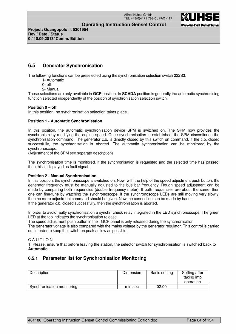
Operating Instruction Genset Control Project: Guangopolo II, 5301954 Rev./ Date / Status 0 / 10.09.2013/ Comm. Edition
461180_Operating Instruction Genset Control Commissioning Edition.doc Page 64 of 134
Alfred Kuhse GmbH TEL +49(0)4171 798-0 , FAX -117
6.5 Generator Synchronisation
The following functions can be preselected using the synchronisation selection switch 232S3: 1- Automatic 0- off 2- Manual These selections are only available in GCP position. In SCADA position is generally the automatic synchronising function selected independently of the position of synchronisation selection switch. Position 0 – off In this position, no synchronisation selection takes place. Position 1 - Automatic Synchronisation In this position, the automatic synchronisation device SPM is switched on. The SPM now provides the synchronism by modifying the engine speed. Once synchronisation is established, the SPM discontinues the synchronisation command. The generator c.b. is directly closed by this switch on command. If the c.b. closed successfully, the synchronisation is aborted. The automatic synchronisation can be monitored by the synchronoscope. (Adjustment of the SPM see separate description) The synchronisation time is monitored. If the synchronisation is requested and the selected time has passed, then this is displayed as fault signal. Position 2 - Manual Synchronisation In this position, the synchronoscope is switched on. Now, with the help of the speed adjustment push button, the generator frequency must be manually adjusted to the bus bar frequency. Rough speed adjustment can be made by comparing both frequencies (double frequency meter). If both frequencies are about the same, then one can fine-tune by watching the synchronoscope. If the synchronoscope LEDs are still moving very slowly, then no more adjustment command should be given. Now the connection can be made by hand. If the generator c.b. closed successfully, then the synchronisation is aborted. In order to avoid faulty synchronisation a synchr. check relay integrated in the LED synchronoscope. The green LED at the top indicates the synchronisation release. The speed adjustment push button in the +GCP panel is only released during the synchronisation. The generator voltage is also compared with the mains voltage by the generator regulator. This control is carried out in order to keep the switch-on peak as low as possible. C A U T I O N 1. Please, ensure that before leaving the station, the selector switch for synchronisation is switched back to Automatic.
6.5.1 Parameter list for Synchronisation Monitoring
Description Dimension Basic setting Setting after
taking into operation
Synchronisation monitoring min:sec 02:00
Operating Instruction Genset Control Project: Guangopolo II, 5301954 Rev./ Date / Status 0 / 10.09.2013/ Comm. Edition
461180_Operating Instruction Genset Control Commissioning Edition.doc Page 65 of 134
Alfred Kuhse GmbH TEL +49(0)4171 798-0 , FAX -117
6.5.2 Generator circuit breaker monitoring
Generator switch off fault The fault signal comes up when the PLC wants to switch off the generator c.b. but fails to switch off after command. When this message is displayed, and a stopping fault occurs, then the mains coupling c.b. is switched off. Generator switch on fault The fault signal comes up when the PLC wants to close the generator c.b. but fails to close after command and after a delay of one second.
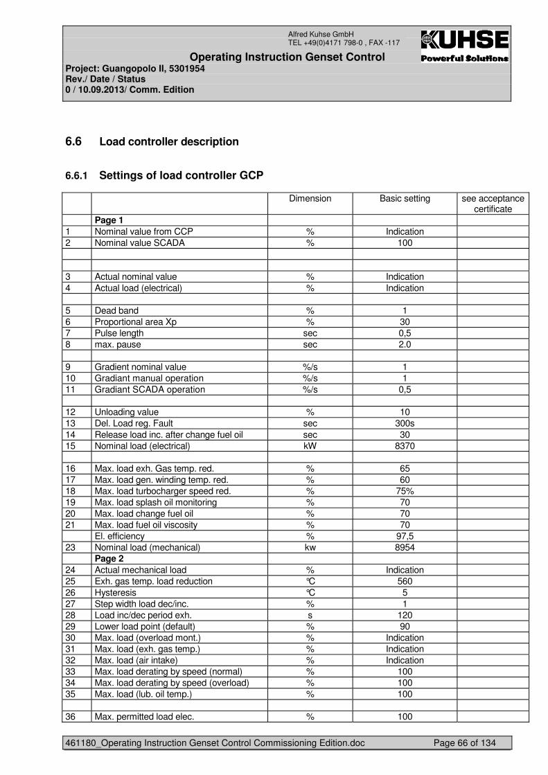
Operating Instruction Genset Control Project: Guangopolo II, 5301954 Rev./ Date / Status 0 / 10.09.2013/ Comm. Edition
461180_Operating Instruction Genset Control Commissioning Edition.doc Page 66 of 134
Alfred Kuhse GmbH TEL +49(0)4171 798-0 , FAX -117
6.6 Load controller description
6.6.1 Settings of load controller GCP
Dimension Basic setting see acceptance certificate
Page 1 1 Nominal value from CCP % Indication 2 Nominal value SCADA % 100 3 Actual nominal value % Indication 4 Actual load (electrical) % Indication 5 Dead band % 1 6 Proportional area Xp % 30 7 Pulse length sec 0,5 8 max. pause sec 2.0 9 Gradient nominal value %/s 1 10 Gradiant manual operation %/s 1 11 Gradiant SCADA operation %/s 0,5 12 Unloading value % 10 13 Del. Load reg. Fault sec 300s 14 Release load inc. after change fuel oil sec 30 15 Nominal load (electrical) kW 8370 16 Max. load exh. Gas temp. red. % 65 17 Max. load gen. winding temp. red. % 60 18 Max. load turbocharger speed red. % 75% 19 Max. load splash oil monitoring % 70 20 Max. load change fuel oil % 70 21 Max. load fuel oil viscosity % 70 El. efficiency % 97,5 23 Nominal load (mechanical) kw 8954 Page 2 24 Actual mechanical load % Indication 25 Exh. gas temp. load reduction °C 560 26 Hysteresis °C 5 27 Step width load dec/inc. % 1 28 Load inc/dec period exh. s 120 29 Lower load point (default) % 90 30 Max. load (overload mont.) % Indication 31 Max. load (exh. gas temp.) % Indication 32 Max. load (air intake) % Indication 33 Max. load derating by speed (normal) % 100 34 Max. load derating by speed (overload) % 100 35 Max. load (lub. oil temp.) % 100 36 Max. permitted load elec. % 100
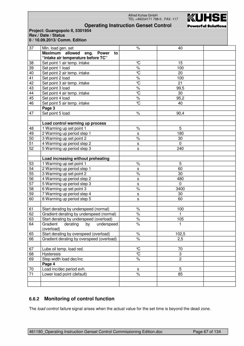
Operating Instruction Genset Control Project: Guangopolo II, 5301954 Rev./ Date / Status 0 / 10.09.2013/ Comm. Edition
461180_Operating Instruction Genset Control Commissioning Edition.doc Page 67 of 134
Alfred Kuhse GmbH TEL +49(0)4171 798-0 , FAX -117
37 Min. load gen. set % 40 Maximum allowed eng. Power to
“intake air temperature before TC”
38 Set point 1 air temp. intake °C 15 39 Set point 1 load % 100 40 Set point 2 air temp. intake °C 20 41 Set point 2 load % 100 42 Set point 3 air temp. intake °C 21 43 Set point 3 load % 99,5 44 Set point 4 air temp. intake °C 30 45 Set point 4 load % 95,2 46 Set point 5 air temp. intake °C 40 Page 3 47 Set point 5 load % 90,4 Load control warming up process 48 1 Warming up set point 1 % 5 49 2 Warming up period step 1 s 180 50 3 Warming up set point 2 % 30 51 4 Warming up period step 2 s 0 52 5 Warming up period step 3 s 240 Load increasing without preheating 53 1 Warming up set point 1 % 5 54 2 Warming up period step 1 s 60 55 3 Warming up set point 2 % 30 56 4 Warming up period step 2 s 480 57 5 Warming up period step 3 s 0 58 6 Warming up set point 3 % 3400 59 7 Warming up period step 4 s 30 60 8 Warming up period step 5 s 60 61 Start derating by underspeed (normal) % 100 62 Gradient derating by underspeed (normal) % 1 63 Start derating by underspeed (overload) % 105 64 Gradient derating by underspeed
(overload) % 1
65 Start derating by overspeed (overload) % 102,5 66 Gradient derating by overspeed (overload) % 2,5 67 Lube oil temp. load red. °C 70 68 Hysteresis °C 3 69 Step width load dec/inc % 2 Page 4 70 Load inc/dec period exh. s 5 71 Lower load point (default) % 85
6.6.2 Monitoring of control function
The load control failure signal arises when the actual value for the set time is beyond the dead zone.
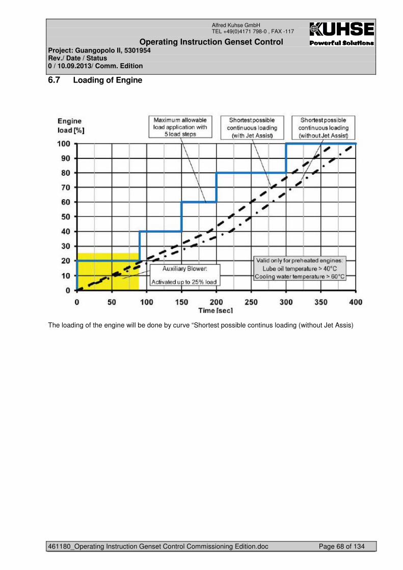
Operating Instruction Genset Control Project: Guangopolo II, 5301954 Rev./ Date / Status 0 / 10.09.2013/ Comm. Edition
461180_Operating Instruction Genset Control Commissioning Edition.doc Page 68 of 134
Alfred Kuhse GmbH TEL +49(0)4171 798-0 , FAX -117
6.7 Loading of Engine
The loading of the engine will be done by curve “Shortest possible continus loading (without Jet Assis)
Operating Instruction Genset Control Project: Guangopolo II, 5301954 Rev./ Date / Status 0 / 10.09.2013/ Comm. Edition
461180_Operating Instruction Genset Control Commissioning Edition.doc Page 69 of 134
Alfred Kuhse GmbH TEL +49(0)4171 798-0 , FAX -117
6.8 Limitations in load range by the PCU (power control unit)
PCU is a Software-System, which limits the maximum power delivery of the engine dependant on surrounding conditions:
• Load reduction dependant on the ambient air temperature • Load reduction because of unacceptable mechanical overload and speed difference • Load reduction because of too high exhaust gas temperature before turbo charger
The permitted load calculated by the PCU always represents the mechanical load to the engine coupling.
6.8.1 Load reduction dependent on ambient air temperature.
The permitted long-term performance is defined by the compatible limit curve. This curve is established in the form of support values (table). By fixing up to 5 temperature support values, the limit values for the long-term performance are interpolated each linearly. The establishing of the actually permissible performance is made in direct dependence of the ambient air temperature.
Operating Instruction Genset Control Project: Guangopolo II, 5301954 Rev./ Date / Status 0 / 10.09.2013/ Comm. Edition
461180_Operating Instruction Genset Control Commissioning Edition.doc Page 70 of 134
Alfred Kuhse GmbH TEL +49(0)4171 798-0 , FAX -117
6.8.2 Load reduction because of too high exhaust gas temperature before turbine.
In case of excess of a pre-set limit value (e.g. 550°C), the permitted load is gradually reduced by steps of 1% of the nominal load until the temperature limit value is undershot, taking into consideration a steady state time of 2 minutes. In case the temperature falls lower than 5°C (set value), the load can be released again in 1% steps until a limit value is reached after the point 1 or 2 of the permitted load. REMARKS All three-load reduction possibilities are always fundamentally calculated through. It is always the lowest that sets the permitted engine load output. The load reductions are limited to Pmin (specific to the plant limit value, or default value). As far as an internal fault in the PCU leads to it, then no maximum permitted load is calculated any more (e.g. Failure of the ambient temperature sensor), then the higher-ranking load control must reduce the load of the engine to Pmin on safety grounds. In order to render load reduction transparent to the client, the following information are visualised on a display: Results of the PCU calculation:
• Display of the maximum permitted mechanical load because of load monitoring • Display of the maximum permitted load because of exhaust gas temperature • Display of the maximum permitted load because of ambient air temperature
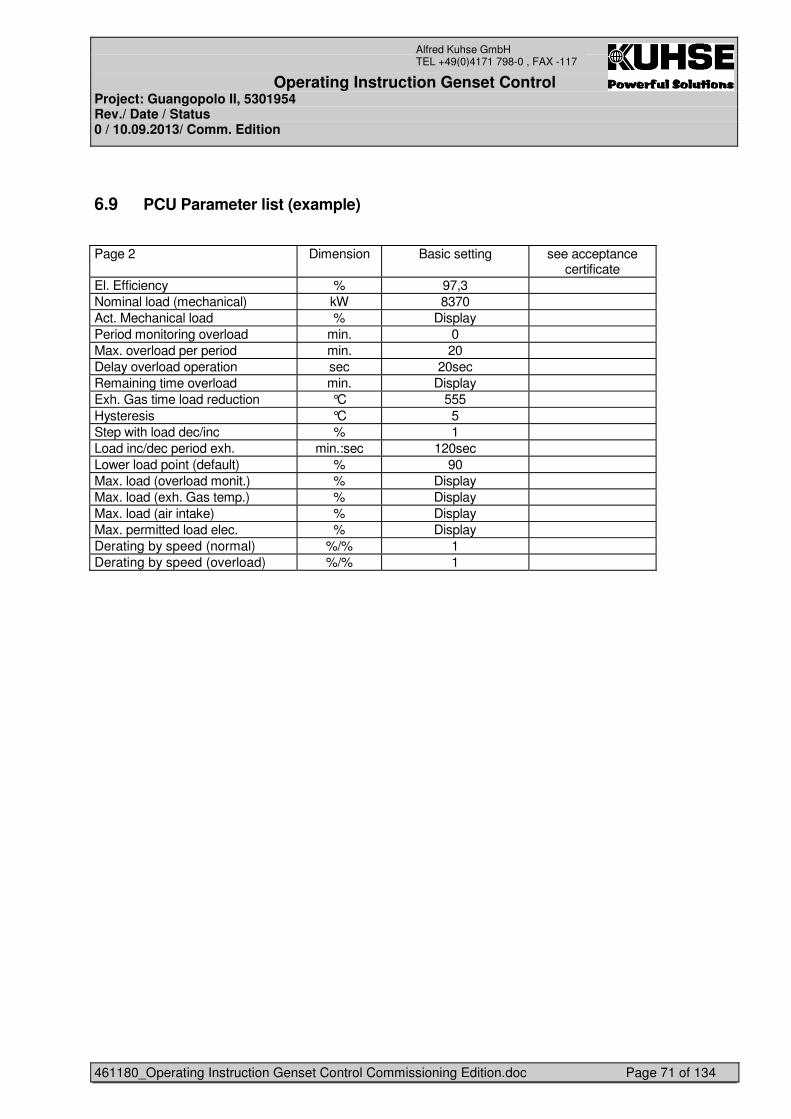
Operating Instruction Genset Control Project: Guangopolo II, 5301954 Rev./ Date / Status 0 / 10.09.2013/ Comm. Edition
461180_Operating Instruction Genset Control Commissioning Edition.doc Page 71 of 134
Alfred Kuhse GmbH TEL +49(0)4171 798-0 , FAX -117
6.9 PCU Parameter list (example)
Page 2 Dimension Basic setting see acceptance
certificate El. Efficiency % 97,3 Nominal load (mechanical) kW 8370 Act. Mechanical load % Display Period monitoring overload min. 0 Max. overload per period min. 20 Delay overload operation sec 20sec Remaining time overload min. Display Exh. Gas time load reduction °C 555 Hysteresis °C 5 Step with load dec/inc % 1 Load inc/dec period exh. min.:sec 120sec Lower load point (default) % 90 Max. load (overload monit.) % Display Max. load (exh. Gas temp.) % Display Max. load (air intake) % Display Max. permitted load elec. % Display Derating by speed (normal) %/% 1 Derating by speed (overload) %/% 1
Operating Instruction Genset Control Project: Guangopolo II, 5301954 Rev./ Date / Status 0 / 10.09.2013/ Comm. Edition
461180_Operating Instruction Genset Control Commissioning Edition.doc Page 72 of 134
Alfred Kuhse GmbH TEL +49(0)4171 798-0 , FAX -117
6.10 Further load limitations
Additionally to the PCU, the following events can lead to load limitations:
• Fault signal from the monitoring of the exhaust gas temperature behind cylinder. • Max. load of gen. Overtemp. • X-1SZH1004A turbocharger speed max. load red. • X-1SZH1004B turbocharger speed max. load red. • X-1TAHHU001 generator winding overtemp. -A Red. • X-1TAHHV001 generator winding overtemp. -A Red. • X-1TAHHW001 generator winding overtemp. -A Red.
If one of the above named monitoring reacts, then the load is reduced to a pre-settable value (Lower load point). Only when the corresponding fault signal is quitted, full load operation will be released. A message „Actual engine nominal load exceeded“ (FE111) is created from the error messages that cause a reduction in power, see the error message bar or generally if an engine overload exists. This message serves to warn the operator that the load must be reduced or another machine started as quickly as possible.
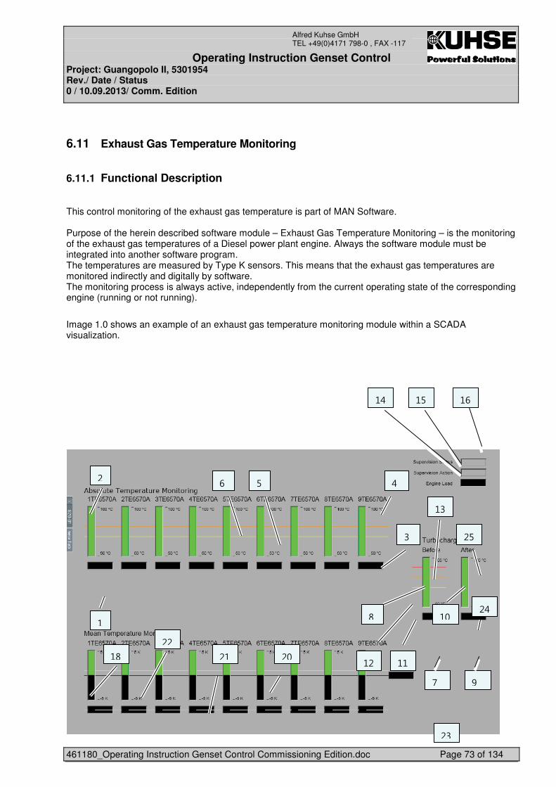
Operating Instruction Genset Control Project: Guangopolo II, 5301954 Rev./ Date / Status 0 / 10.09.2013/ Comm. Edition
461180_Operating Instruction Genset Control Commissioning Edition.doc Page 73 of 134
Alfred Kuhse GmbH TEL +49(0)4171 798-0 , FAX -117
6.11 Exhaust Gas Temperature Monitoring
6.11.1 Functional Description
This control monitoring of the exhaust gas temperature is part of MAN Software. Purpose of the herein described software module – Exhaust Gas Temperature Monitoring – is the monitoring of the exhaust gas temperatures of a Diesel power plant engine. Always the software module must be integrated into another software program. The temperatures are measured by Type K sensors. This means that the exhaust gas temperatures are monitored indirectly and digitally by software. The monitoring process is always active, independently from the current operating state of the corresponding engine (running or not running).
�Image 1.0 shows an example of an exhaust gas temperature monitoring module within a SCADA visualization.
�
�
�
�
�
�
�
�
�
�
�
�
�
�
�
�
�
�
�
�
�
�
�
�
� $� �� 5�
��
�$�����5�
�7
�5�
���
������
���
�� ��
��
��
��
�
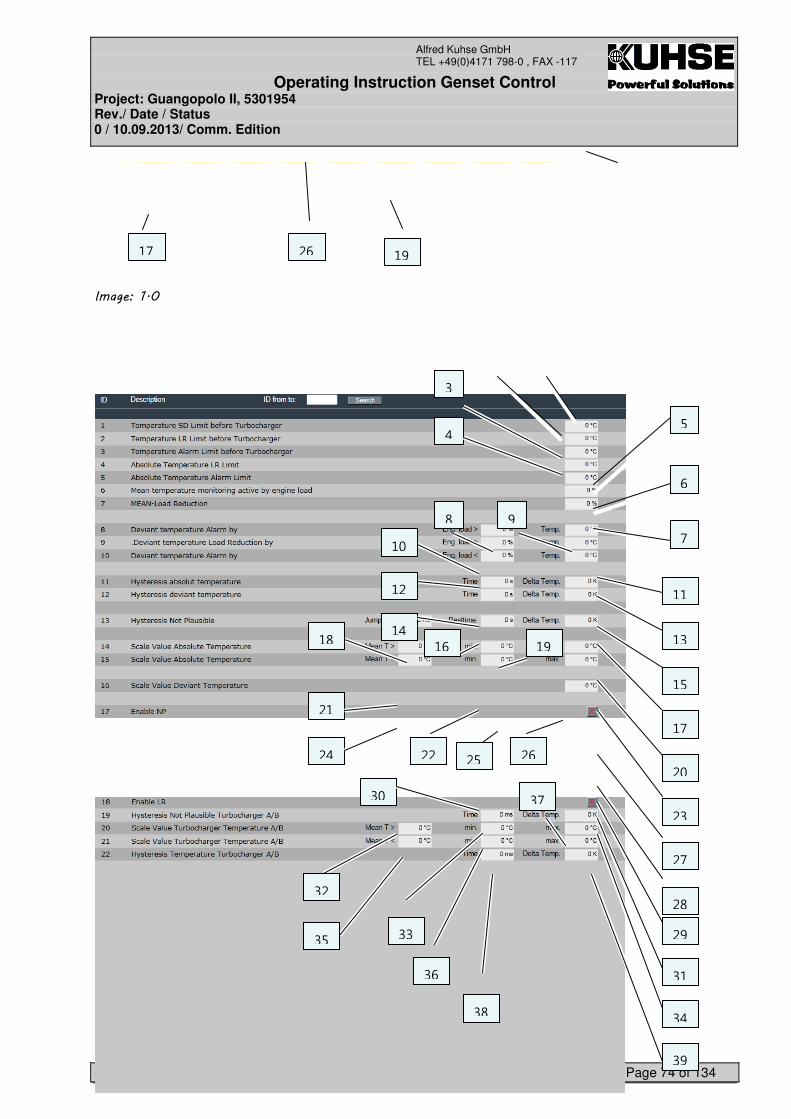
Operating Instruction Genset Control Project: Guangopolo II, 5301954 Rev./ Date / Status 0 / 10.09.2013/ Comm. Edition
461180_Operating Instruction Genset Control Commissioning Edition.doc Page 74 of 134
Alfred Kuhse GmbH TEL +49(0)4171 798-0 , FAX -117
�
�
�
�
�
����������
�
�
�
�
�
�
�
�
�
�
�
�
�
�
�
�
�
�
�
�
�
�
�
�
�
�
�
�
�
�
���7 �$
�
5�
$
7
��
���5
��
�$
�7��
�5��
��
�7
�
��
��
�5
��
��
�
��
�
��
��
�
�� �$��
��
��
��
�$
�7
Operating Instruction Genset Control Project: Guangopolo II, 5301954 Rev./ Date / Status 0 / 10.09.2013/ Comm. Edition
461180_Operating Instruction Genset Control Commissioning Edition.doc Page 75 of 134
Alfred Kuhse GmbH TEL +49(0)4171 798-0 , FAX -117
�
�
�
�
�
�
��������
Operating Instruction Genset Control Project: Guangopolo II, 5301954 Rev./ Date / Status 0 / 10.09.2013/ Comm. Edition
461180_Operating Instruction Genset Control Commissioning Edition.doc Page 76 of 134
Alfred Kuhse GmbH TEL +49(0)4171 798-0 , FAX -117
6.11.2 Exhaust gas temperature monitoring functions
Several sensors measure the current absolute value of the exhaust gas temperature constantly. Measuring points exist at every cylinder of an engine and at the turbo charger. All measured values are analysed by the PLC. Depending on the result of every analysis the PLC sends signals to other software modules, e.g. a SCADA visualisation.
�The exhaust gas temperature monitoring is divided into the following sub functions.
Monitoring maximal value at cylinder Each sensor monitors the exceeding of the allowed maximal value. The following criteria are monitored:
�If the measured value exceeds a predefined first temperature limit, the alarm signal PRE ALRAM will be generated and sent to the SCADA visualisation.
�If the measured value exceeds a predefined second temperature limit, the signal ENGINE LOAD REDUCTION will be sent from the PLC to the SCADA visualisation and other software modules within the PLC.
Monitoring mean value deviation at cylinder The PLC calculates a mean value of all temperature measuring sensors with status – plausible -. Basis for the calculated mean value are the present absolute values. Further on the PLC calculates for every sensor the deviation of the absolute value from the mean value. This is necessary to prevent that the temperature at a single measuring point deviates too much from the calculated mean value.
�If the calculated deviation exceeds a first temperature limit, the alarm PRE ALARM MEAN SENSOR will be generated and sent to the SCADA visualisation.
�If the calculated deviation exceeds a second temperature limit, additionally the alarm ALARM MEAN SENSOR is generated and sent to the SCADA visualisation. Optional the signal ENGINE LOAD REDUCTION will be sent from the PLC to the SCADA visualisation and other software modules within the PLC.
�A second temperature limit is only active if the corresponding genset is running with a load of more than 60 % (default value). The default value can be changed.
Operating Instruction Genset Control Project: Guangopolo II, 5301954 Rev./ Date / Status 0 / 10.09.2013/ Comm. Edition
461180_Operating Instruction Genset Control Commissioning Edition.doc Page 77 of 134
Alfred Kuhse GmbH TEL +49(0)4171 798-0 , FAX -117
Monitoring maximal value before turbo charger The exceeding of the allowed maximal value is monitored. The following criteria are monitored:
�If the measured value exceeds a predefined first temperature limit, the alarm signal PRE ALRAM will be generated and sent to the SCADA visualization.
�If the measured value exceeds a predefined second temperature limit the alarm signal ALARM SENSOR will be sent from the PLC to the SCADA visualization. The signal ENGINE LOAD REDUCTION will be sent to the SCADA visualization and other software modules within the PLC.
�If the measured value exceeds a predefined third temperature limit, the signals OVERTEMPERATURE SENSOR and ENGINE SHUTDOWN will be created and sent from the PLC to the SCADA visualization and other software modules within the PLC.
Temperature value after turbo charger At this measuring point no monitoring of the exhaust gas temperature takes place. But the measured absolute value of the present exhaust gas temperature is sent to the SCADA visualization constantly.
Reset All generated alarm signals are no longer active if the following conditions are given:
• %� ��� � ���,���� �(� ����! �����#����������* ��, �/��� �� ���#�� !� ���� ��!���
��� �#����
• 2���*�/� �� � ��/����� �
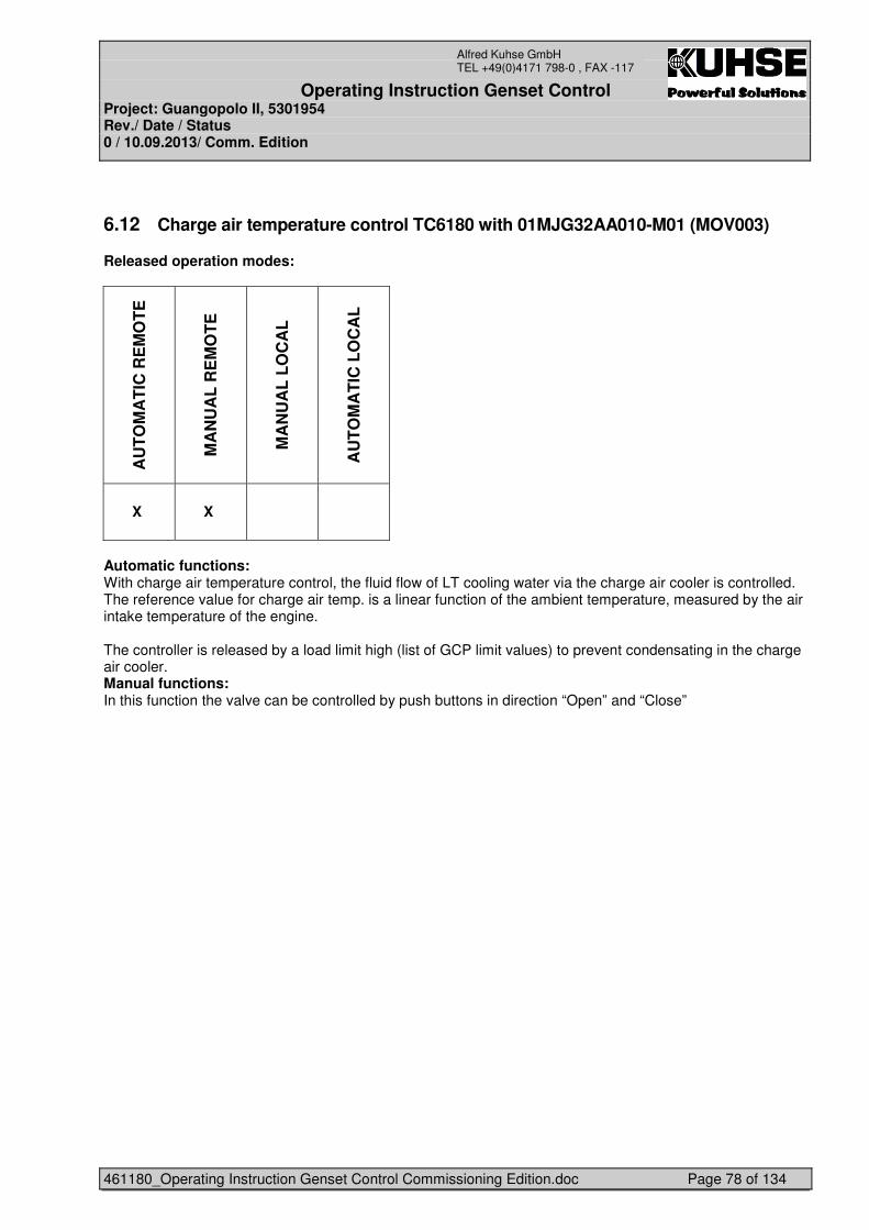
Operating Instruction Genset Control Project: Guangopolo II, 5301954 Rev./ Date / Status 0 / 10.09.2013/ Comm. Edition
461180_Operating Instruction Genset Control Commissioning Edition.doc Page 78 of 134
Alfred Kuhse GmbH TEL +49(0)4171 798-0 , FAX -117
6.12 Charge air temperature control TC6180 with 01MJG32AA010-M01 (MOV003)
Released operation modes:
AU
TO
MA
TIC
RE
MO
TE
MA
NU
AL
RE
MO
TE
MA
NU
AL
LO
CA
L
AU
TO
MA
TIC
LO
CA
L
X X
Automatic functions: With charge air temperature control, the fluid flow of LT cooling water via the charge air cooler is controlled. The reference value for charge air temp. is a linear function of the ambient temperature, measured by the air intake temperature of the engine. The controller is released by a load limit high (list of GCP limit values) to prevent condensating in the charge air cooler. Manual functions: In this function the valve can be controlled by push buttons in direction “Open” and “Close”
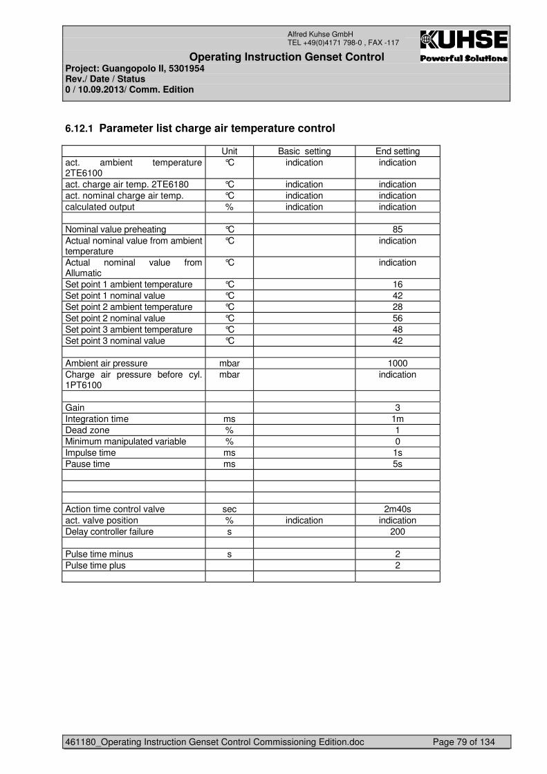
Operating Instruction Genset Control Project: Guangopolo II, 5301954 Rev./ Date / Status 0 / 10.09.2013/ Comm. Edition
461180_Operating Instruction Genset Control Commissioning Edition.doc Page 79 of 134
Alfred Kuhse GmbH TEL +49(0)4171 798-0 , FAX -117
6.12.1 Parameter list charge air temperature control
Unit Basic setting End setting act. ambient temperature 2TE6100
°C indication indication
act. charge air temp. 2TE6180 °C indication indication act. nominal charge air temp. °C indication indication calculated output % indication indication Nominal value preheating °C 85 Actual nominal value from ambient temperature
°C indication
Actual nominal value from Allumatic
°C indication
Set point 1 ambient temperature °C 16 Set point 1 nominal value °C 42 Set point 2 ambient temperature °C 28 Set point 2 nominal value °C 56 Set point 3 ambient temperature °C 48 Set point 3 nominal value °C 42 Ambient air pressure mbar 1000 Charge air pressure before cyl. 1PT6100
mbar indication
Gain 3 Integration time ms 1m Dead zone % 1 Minimum manipulated variable % 0 Impulse time ms 1s Pause time ms 5s Action time control valve sec 2m40s act. valve position % indication indication Delay controller failure s 200 Pulse time minus s 2 Pulse time plus 2
Operating Instruction Genset Control Project: Guangopolo II, 5301954 Rev./ Date / Status 0 / 10.09.2013/ Comm. Edition
461180_Operating Instruction Genset Control Commissioning Edition.doc Page 80 of 134
Alfred Kuhse GmbH TEL +49(0)4171 798-0 , FAX -117
• CHATCO curve Example, pls. look MAN requirements for the used engine
6.12.2 Function of controller
• Monitoring of the control valve The error message “X-1TC6180 Chatco c.w. control fault” is created, if the control value is recognised as failed.
6.12.3 Selection operating mode
Following modes are selectable: • Automatic • Manual
Position Automatic: In this position automatic control is released as described previously. Position Manual: This position is intended for service purposes. In this mode are to sets of push buttons selectabele:
• Valve command Open and Close • Valve command Open and Close by pulses
Valve command Open and Close By pressing the button Open, the valve goes in open position. By pressing the button Close, the valve goes in close position. Valve command Open and Close by pulses By pressing the button Open, the valve goes one step in open position. By pressing the button Close, the valve goes one step in close position.
Monitoring of the control valve The error message “1TC6180 Chatco c.w. control fault” is created, if the control value is recognised as failed.
Operating Instruction Genset Control Project: Guangopolo II, 5301954 Rev./ Date / Status 0 / 10.09.2013/ Comm. Edition
461180_Operating Instruction Genset Control Commissioning Edition.doc Page 81 of 134
Alfred Kuhse GmbH TEL +49(0)4171 798-0 , FAX -117
6.12.4 Allumatic
Automatic Charge Air Control
AlLumatiC – CHARGE AIR TEMPERATURE CONTROL The requirement of the Allumatic-System is to control the charge air temperature regarding to its dewpoint, i.e. to keep the charge air temperature as low as possible but still high enough so the air bonded water vapor will not condensate. The setpoint of the charge air temperature is the charge air dewpoint temperature before cylinder + 1°C (safety margin). The lower the charge air temperature the lower is the NOx value and also the fuel oil consumption of an engine. The airbonded water vapor reduces the NOx value also. In case of fault by the Allumatic system, a switch over to CHATCO (charge air control depending of the ambient air temperature) is necessary.
Operation Modes The operation modes of the Allumatic are Manual Remote and Automatic Remote
• Manual Remote This mode has to be selected at SCADA by soft touch buttons. With these the operator can move the valve between the position A-AB (heat exchanger active cooled) and B-AB (heat exchanger bypassed).
• Automatic Remote The software controller is active with LT cooling water pump P025.
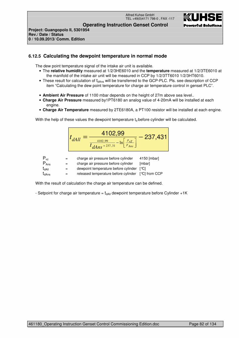
Operating Instruction Genset Control Project: Guangopolo II, 5301954 Rev./ Date / Status 0 / 10.09.2013/ Comm. Edition
461180_Operating Instruction Genset Control Commissioning Edition.doc Page 82 of 134
Alfred Kuhse GmbH TEL +49(0)4171 798-0 , FAX -117
6.12.5 Calculating the dewpoint temperature in normal mode
The dew point temperature signal of the intake air unit is available. • The relative humidity measured at 1/2/3HE6010 and the temperature measured at 1/2/3TE6010 at
the manifold of the intake air unit will be measured in CCP by 1/2/3TT6010 1/2/3HT6010. • These result for calculation of tdAns will be transferred to the GCP-PLC. Pls. see description of CCP
item “Calculating the dew point temperature for charge air temperature control in genset PLC”.
• Ambient Air Pressure of 1100 mbar depends on the height of 27m above sea level.. • Charge Air Pressure measured by1PT6180 an analog value of 4-20mA will be installed at each
engine. • Charge Air Temperature measured by 2TE6180A, a PT100 resistor will be installed at each engine.
With the help of these values the dewpoint temperature td before cylinder will be calculated.
Pvz = charge air pressure before cylinder 4150 [mbar] PAns = charge air pressure before cylinder [mbar] tdAll = dewpoint temperature before cylinder [°C] tdAns = released temperature before cylinder [°C] from CCP
With the result of calculation the charge air temperature can be defined. - Setpoint for charge air temperature = tdAll dewpoint temperature before Cylinder +1K
237,4314102,99
−=
���
���
−+ Ansp
vZp
dAns
dAllt
tln
31,237
99,4102
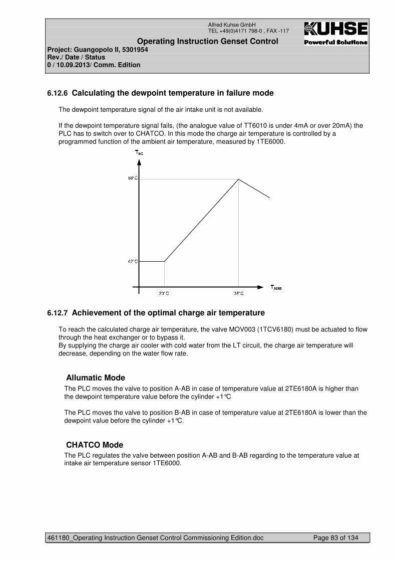
Operating Instruction Genset Control Project: Guangopolo II, 5301954 Rev./ Date / Status 0 / 10.09.2013/ Comm. Edition
461180_Operating Instruction Genset Control Commissioning Edition.doc Page 83 of 134
Alfred Kuhse GmbH TEL +49(0)4171 798-0 , FAX -117
6.12.6 Calculating the dewpoint temperature in failure mode
The dewpoint temperature signal of the air intake unit is not available. If the dewpoint temperature signal fails, (the analogue value of TT6010 is under 4mA or over 20mA) the PLC has to switch over to CHATCO. In this mode the charge air temperature is controlled by a programmed function of the ambient air temperature, measured by 1TE6000.
6.12.7 Achievement of the optimal charge air temperature
To reach the calculated charge air temperature, the valve MOV003 (1TCV6180) must be actuated to flow through the heat exchanger or to bypass it. By supplying the charge air cooler with cold water from the LT circuit, the charge air temperature will decrease, depending on the water flow rate.
Allumatic Mode The PLC moves the valve to position A-AB in case of temperature value at 2TE6180A is higher than the dewpoint temperature value before the cylinder +1°C The PLC moves the valve to position B-AB in case of temperature value at 2TE6180A is lower than the dewpoint value before the cylinder +1°C.
CHATCO Mode The PLC regulates the valve between position A-AB and B-AB regarding to the temperature value at intake air temperature sensor 1TE6000.
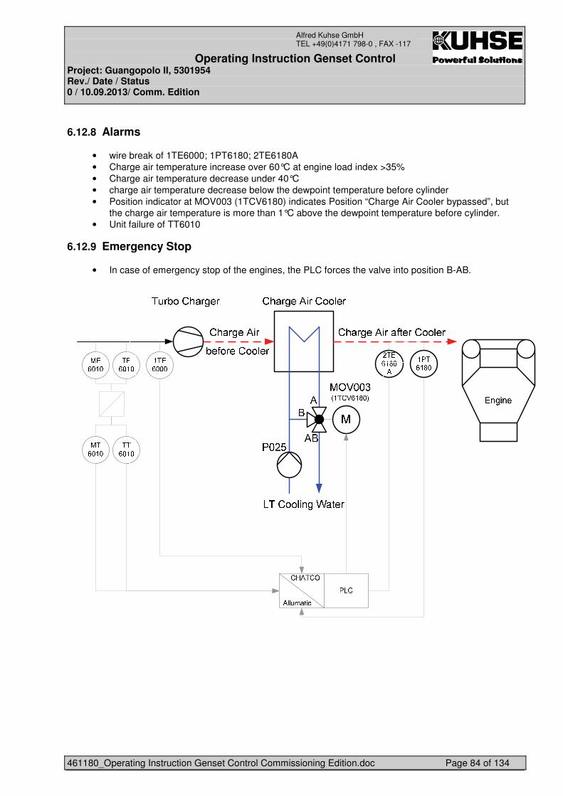
Operating Instruction Genset Control Project: Guangopolo II, 5301954 Rev./ Date / Status 0 / 10.09.2013/ Comm. Edition
461180_Operating Instruction Genset Control Commissioning Edition.doc Page 84 of 134
Alfred Kuhse GmbH TEL +49(0)4171 798-0 , FAX -117
6.12.8 Alarms
• wire break of 1TE6000; 1PT6180; 2TE6180A • Charge air temperature increase over 60°C at engine load index >35% • Charge air temperature decrease under 40°C • charge air temperature decrease below the dewpoint temperature before cylinder • Position indicator at MOV003 (1TCV6180) indicates Position “Charge Air Cooler bypassed”, but
the charge air temperature is more than 1°C above the dewpoint temperature before cylinder. • Unit failure of TT6010
6.12.9 Emergency Stop
• In case of emergency stop of the engines, the PLC forces the valve into position B-AB.
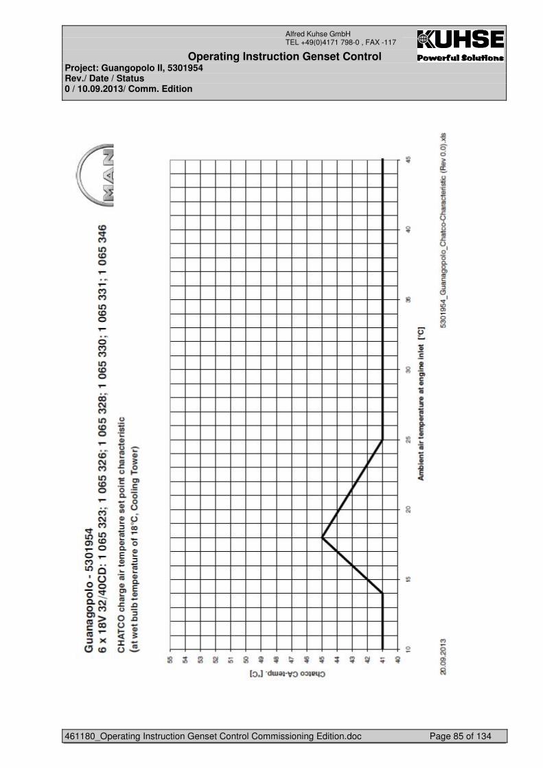
Operating Instruction Genset Control Project: Guangopolo II, 5301954 Rev./ Date / Status 0 / 10.09.2013/ Comm. Edition
461180_Operating Instruction Genset Control Commissioning Edition.doc Page 85 of 134
Alfred Kuhse GmbH TEL +49(0)4171 798-0 , FAX -117
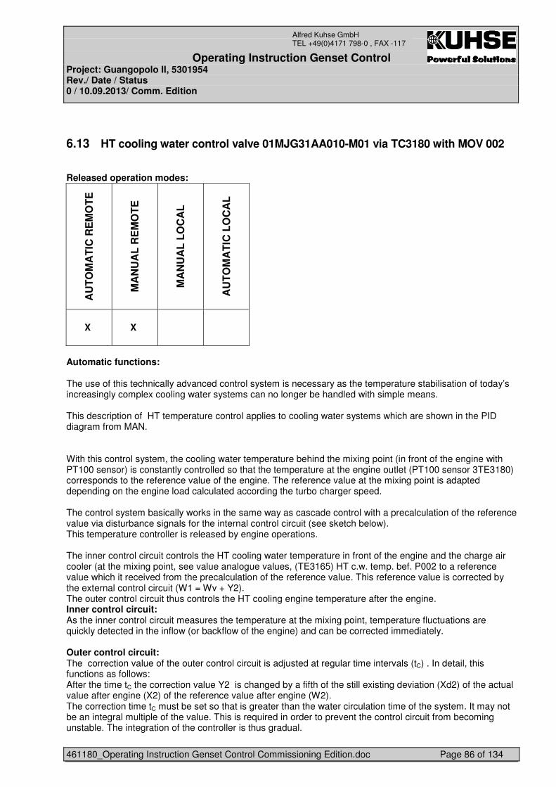
Operating Instruction Genset Control Project: Guangopolo II, 5301954 Rev./ Date / Status 0 / 10.09.2013/ Comm. Edition
461180_Operating Instruction Genset Control Commissioning Edition.doc Page 86 of 134
Alfred Kuhse GmbH TEL +49(0)4171 798-0 , FAX -117
6.13 HT cooling water control valve 01MJG31AA010-M01 via TC3180 with MOV 002
Released operation modes:
AU
TO
MA
TIC
RE
MO
TE
MA
NU
AL
RE
MO
TE
MA
NU
AL
LO
CA
L
AU
TO
MA
TIC
LO
CA
L
X X
Automatic functions: The use of this technically advanced control system is necessary as the temperature stabilisation of today’s increasingly complex cooling water systems can no longer be handled with simple means. This description of HT temperature control applies to cooling water systems which are shown in the PID diagram from MAN. With this control system, the cooling water temperature behind the mixing point (in front of the engine with PT100 sensor) is constantly controlled so that the temperature at the engine outlet (PT100 sensor 3TE3180) corresponds to the reference value of the engine. The reference value at the mixing point is adapted depending on the engine load calculated according the turbo charger speed. The control system basically works in the same way as cascade control with a precalculation of the reference value via disturbance signals for the internal control circuit (see sketch below). This temperature controller is released by engine operations. The inner control circuit controls the HT cooling water temperature in front of the engine and the charge air cooler (at the mixing point, see value analogue values, (TE3165) HT c.w. temp. bef. P002 to a reference value which it received from the precalculation of the reference value. This reference value is corrected by the external control circuit (W1 = Wv + Y2). The outer control circuit thus controls the HT cooling engine temperature after the engine. Inner control circuit: As the inner control circuit measures the temperature at the mixing point, temperature fluctuations are quickly detected in the inflow (or backflow of the engine) and can be corrected immediately. Outer control circuit: The correction value of the outer control circuit is adjusted at regular time intervals (tC) . In detail, this functions as follows: After the time tC the correction value Y2 is changed by a fifth of the still existing deviation (Xd2) of the actual value after engine (X2) of the reference value after engine (W2). The correction time tC must be set so that is greater than the water circulation time of the system. It may not be an integral multiple of the value. This is required in order to prevent the control circuit from becoming unstable. The integration of the controller is thus gradual.
Operating Instruction Genset Control Project: Guangopolo II, 5301954 Rev./ Date / Status 0 / 10.09.2013/ Comm. Edition
461180_Operating Instruction Genset Control Commissioning Edition.doc Page 87 of 134
Alfred Kuhse GmbH TEL +49(0)4171 798-0 , FAX -117
The correction value is limited to ±Y2max so that the reference value W1, in case of control parameters which are not set optimally, is not too far. This prevents instability of the control circuit. If larger corrections than ±Y2max are required, the characteristic curve (temperature difference ΔT between the mixing point and the engine outlet is a function of the actual load of engine) is not set correctly for precalculation of the reference value. Precalculation of the reference value: Precalculation of the reference value is used to be able to respond quickly to changes in load or changes in the flow rate without having to wait for the considerable downtime of the control paths. The precalculation of the reference value is carried out primarily with the actual load signal. The reference value at the mixing point is calculated in advance from the reference value after the engine via a characteristic curve determined (by measurement) during a trial run and on commissioning, which specified the temperature difference ΔT between the mixing point (in front of the engine and the charge air cooler) and the engine outlet as a function of the actual load: Wv = W2 - ΔT If the characteristic curve is set more exactly, the overlaid (outer) control circuit only needs to correct minor remaining deviations. A sudden change in load results in a change in temperature with some delay due to the inertia of thermal systems (heat transmission time tHT). For this reason, the actual load may not be directly processed as input signals for control, but must first be delayed in time by means of a filter element. On the other hand, the control must also be carried out in a short amount of time. This is necessary as the cooling water requires a particular amount of time (tF) to flow from the mixing point to the charge air cooler. With long pipes between the mixing point and the charge air cooler, the time set for the filter element is somewhat reduced (tPT1 = tHT - tF). This temperature controller is released by engine operations. The temperature controller takes care of all the control tasks (controller 1, controller 2 and precalculation of the reference value). It only requires the appropriate input signals to do this: • Actual value W1 at the mixing point (Pt100 resistance thermometer, see value eng. inlet cw. temp.) • Actual value W2 after engine (Pt100 resistance thermometer 3TE3180 cyl. c.w. temp. beh. Engine) • Actual load signal, calculated in the load controller • Actual turbo charger speed signal Manual functions: In this function the valve can be controlled by entering a set point in percentage “Set point for manual operation”. The controller will move then to this set point.
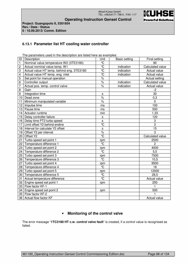
Operating Instruction Genset Control Project: Guangopolo II, 5301954 Rev./ Date / Status 0 / 10.09.2013/ Comm. Edition
461180_Operating Instruction Genset Control Commissioning Edition.doc Page 88 of 134
Alfred Kuhse GmbH TEL +49(0)4171 798-0 , FAX -117
6.13.1 Parameter list HT cooling water controller
The parameters used in the description are listed here as examples:
ID Description Unit Basic setting Final setting 1 Nominal value temperature W2 (3TE3180) °C 90 2 Actual nominal value temp. W1 °C indication Calculated value 3 Actual value HT temp. behind eng. 3TE3180 °C indication Actual value 4 Actual value HT temp. eng. inlet °C indication Actual value 5 Set point for manual operation % Actual setting 6 Controller output % indication Calculated value 7 Actual pos. temp. control valve % indication Actual value 8 Gain -2 9 Integration time s 30 10 Dead zone % 0,3 11 Minimum manipulated variable % 0 12 Impulse time ms 100 13 Pause time ms 500 14 Actuator runtime min 1,33 15 Delay controller failure s 120 16 Delay time PT2 turbo speed s 3 17 Limit offset Y2 behind endine °C 3 18 Interval for calculate Y2 offset s 15 19 Offset Y2 per interval % 3 20 Offset Y2 °C Calculated value 21 Turbo speed set point 1 rpm 2500 22 Temperature difference 1 °C 2 23 Turbo speed set point 2 rpm 4000 24 Temperature difference 2 °C 5,5 25 Turbo speed set point 3 rpm 7500 26 Temperature difference 3 °C 10,5 27 Turbo speed set point 4 rpm 9500 28 Temperature difference 4 °C 18 29 Turbo speed set point 5 rpm 12000 30 Temperature difference 5 °C 28,5 31 Actual temperature difference °C Actual value 32 Engine speed set point 1 rpm 250 33 Flow factor KF-1 1 34 Engine speed set point 2 rpm 500 35 Flow factor KF-2 1 36 Actual flow factor KF Actual value
• Monitoring of the control valve The error message “1TC3180 HT c.w. control valve fault” is created, if a control value is recognised as failed.
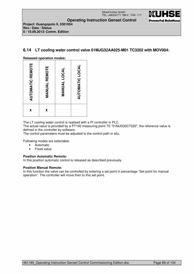
Operating Instruction Genset Control Project: Guangopolo II, 5301954 Rev./ Date / Status 0 / 10.09.2013/ Comm. Edition
461180_Operating Instruction Genset Control Commissioning Edition.doc Page 89 of 134
Alfred Kuhse GmbH TEL +49(0)4171 798-0 , FAX -117
6.14 LT cooling water control valve 01MJG32AA025-M01 TC3202 with MOV004:
Released operation modes:
AU
TO
MA
TIC
RE
MO
TE
MA
NU
AL
RE
MO
TE
MA
NU
AL
LO
CA
L
AU
TO
MA
TIC
LO
CA
L
X X
The LT cooling water control is realised with a PI controller in PLC. The actual value is provided by a PT100 measuring point TE “01MJG32CT220”, the reference value is defined in the controller by software. The control parameters must be adjusted to the control path in situ. Following modes are selectable:
• Automatic • Fixed value
Position Automatic Remote: In this position automatic control is released as described previously. Position Manual Remote: In this function the valve can be controlled by entering a set point in percentage “Set point for manual operation”. The controller will move then to this set point.
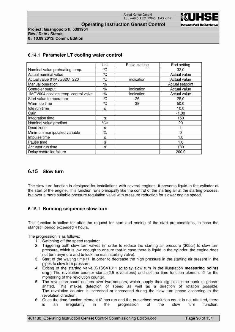
Operating Instruction Genset Control Project: Guangopolo II, 5301954 Rev./ Date / Status 0 / 10.09.2013/ Comm. Edition
461180_Operating Instruction Genset Control Commissioning Edition.doc Page 90 of 134
Alfred Kuhse GmbH TEL +49(0)4171 798-0 , FAX -117
6.14.1 Parameter LT cooling water control
Unit Basic setting End setting Nominal value preheating temp. °C 32,0 Actual nominal value °C Actual value Actual value 01MJG32CT220 °C indication Actual value Manual operation % Actual setpoint Controler output % indication Actual value 1MOV004 position temp. control valve % indication Actual value Start value temperature °C 26 25,0 Warm up time °C 38 50,0 Idle run time s 10,0 Gain -1,00 Integration time s 150 Nominal value gradiant %/s 20 Dead zone s 1 Minimum manipulated variable % 0 Impulse time s 1,0 Pause time s 1,0 Actuator run time s 180 Delay controller failure 200,0
6.15 Slow turn
The slow turn function is designed for installations with several engines; it prevents liquid in the cylinder at the start of the engine. This function runs principally like the control of the starting air at the starting process, but over a more suitable pressure regulation valve with pressure reduction for slower engine speed.
6.15.1 Running sequence slow turn
This function is called for after the request for start and ending of the start pre-conditions, in case the standstill period exceeded 4 hours. The progression is as follows:
1. Switching off the speed regulator 2. Triggering both slow turn valves (in order to reduce the starting air pressure (30bar) to slow turn
pressure, which is low enough to ensure that in case there is liquid in the cylinder, the engine does not turn anymore and to lock the main starting valve).
3. Start of the waiting time t1, in order to decrease the high pressure in the starting air present in the pipes to slow turn pressure.
4. Exiting of the starting valve X-1SSV1011 (display slow turn in the illustration measuring points eng.) The revolution counter starts (2,5 revolutions) and set the time function element t2 for the monitoring of the revolution counter.
5. The revolution count ensues over two sensors, which supply their signals to the controls phase-shifted. This makes detection of speed as well as a direction of rotation possible. The revolution counter is increased or decreased during the slow turn phase according to the revolution direction.
6. Once the time function element t2 has run and the prescribed revolution count is not attained, there is an irregularity in the progression of the slow turn function.
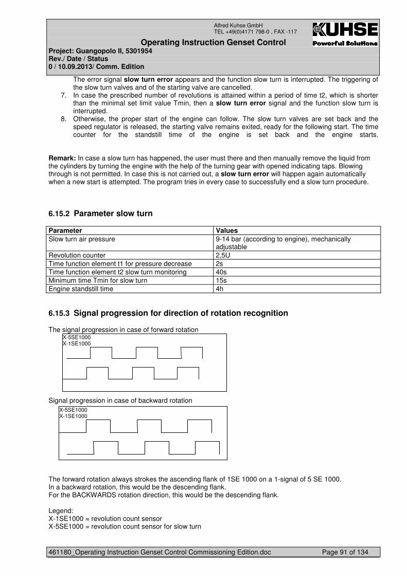
Operating Instruction Genset Control Project: Guangopolo II, 5301954 Rev./ Date / Status 0 / 10.09.2013/ Comm. Edition
461180_Operating Instruction Genset Control Commissioning Edition.doc Page 91 of 134
Alfred Kuhse GmbH TEL +49(0)4171 798-0 , FAX -117
The error signal slow turn error appears and the function slow turn is interrupted. The triggering of the slow turn valves and of the starting valve are cancelled.
7. In case the prescribed number of revolutions is attained within a period of time t2, which is shorter than the minimal set limit value Tmin, then a slow turn error signal and the function slow turn is interrupted.
8. Otherwise, the proper start of the engine can follow. The slow turn valves are set back and the speed regulator is released, the starting valve remains exited, ready for the following start. The time counter for the standstill time of the engine is set back and the engine starts.
Remark: In case a slow turn has happened, the user must there and then manually remove the liquid from the cylinders by turning the engine with the help of the turning gear with opened indicating taps. Blowing through is not permitted. In case this is not carried out, a slow turn error will happen again automatically when a new start is attempted. The program tries in every case to successfully end a slow turn procedure.
6.15.2 Parameter slow turn
Parameter Values Slow turn air pressure 9-14 bar (according to engine), mechanically
adjustable Revolution counter 2,5U Time function element t1 for pressure decrease 2s Time function element t2 slow turn monitoring 40s Minimum time Tmin for slow turn 15s Engine standstill time 4h
6.15.3 Signal progression for direction of rotation recognition
The signal progression in case of forward rotation Signal progression in case of backward rotation The forward rotation always strokes the ascending flank of 1SE 1000 on a 1-signal of 5 SE 1000. In a backward rotation, this would be the descending flank. For the BACKWARDS rotation direction, this would be the descending flank. Legend: X-1SE1000 = revolution count sensor X-5SE1000 = revolution count sensor for slow turn
X-5SE1000 X-1SE1000
X-5SE1000 X-1SE1000
Operating Instruction Genset Control Project: Guangopolo II, 5301954 Rev./ Date / Status 0 / 10.09.2013/ Comm. Edition
461180_Operating Instruction Genset Control Commissioning Edition.doc Page 92 of 134
Alfred Kuhse GmbH TEL +49(0)4171 798-0 , FAX -117
6.16 Ajdusting instruction of software PID-controller
Pls. look at this file “Simatic Standard PID Control_Stdpid_e.pdf” in folder “Operation instruction”.
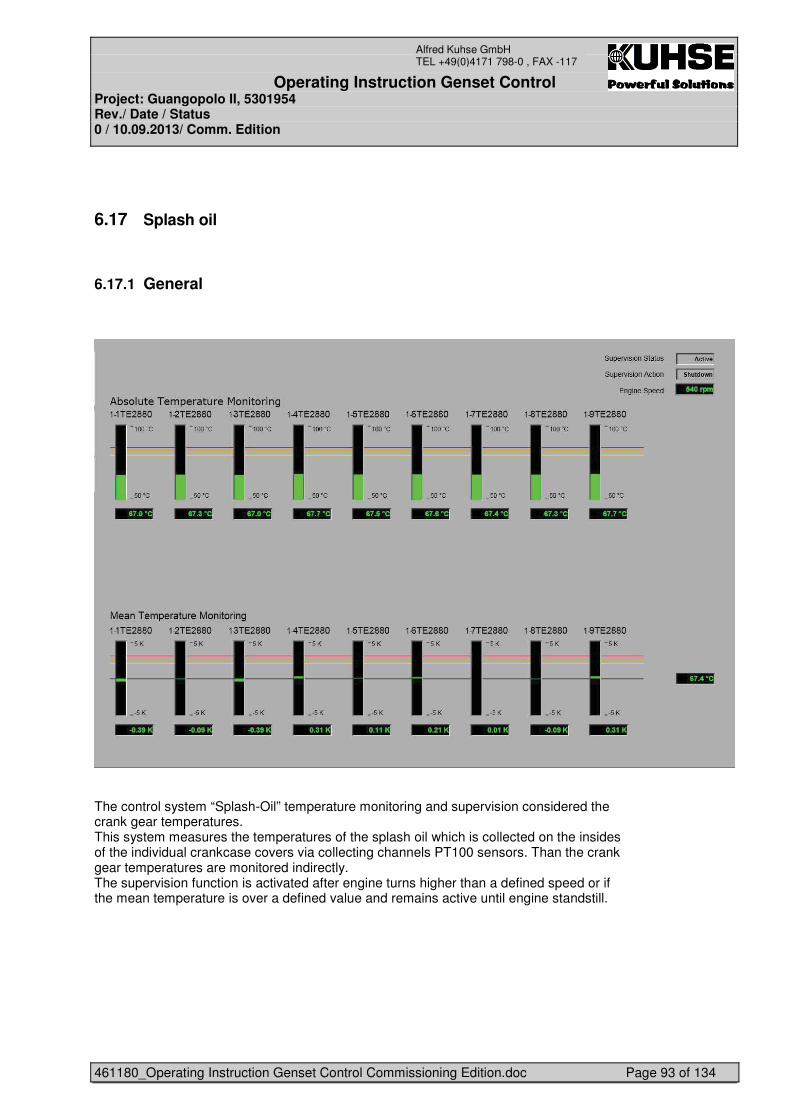
Operating Instruction Genset Control Project: Guangopolo II, 5301954 Rev./ Date / Status 0 / 10.09.2013/ Comm. Edition
461180_Operating Instruction Genset Control Commissioning Edition.doc Page 93 of 134
Alfred Kuhse GmbH TEL +49(0)4171 798-0 , FAX -117
6.17 Splash oil
6.17.1 General
The control system “Splash-Oil” temperature monitoring and supervision considered the crank gear temperatures. This system measures the temperatures of the splash oil which is collected on the insides of the individual crankcase covers via collecting channels PT100 sensors. Than the crank gear temperatures are monitored indirectly. The supervision function is activated after engine turns higher than a defined speed or if the mean temperature is over a defined value and remains active until engine standstill.
Operating Instruction Genset Control Project: Guangopolo II, 5301954 Rev./ Date / Status 0 / 10.09.2013/ Comm. Edition
461180_Operating Instruction Genset Control Commissioning Edition.doc Page 94 of 134
Alfred Kuhse GmbH TEL +49(0)4171 798-0 , FAX -117
6.17.2 Subfunctions
The SPLASH OIL temperature monitoring is divided into the following sub functions
6.17.3 Monitoring Regarding Maximum Value Exceeding
For each sensor the exceeding of the maximal value is supervised. The following criteria are for supervision: - If the measured value in the range of values, no alarm is generated
- Value under the pre alarm border the bar graph is green - If the measured value exceeds the first temperature limit and elapsed a certain time with 3 seconds, the alarm "Splash Oil Pre Alarm” is generated.
- Value from the pre alarm border the bar graph is yellow - If the measured value exceeds the second temperature limit and elapsed a certain time with 3 seconds, additionally the alarm "Splash Oil Alarm” is generated and the request “Engine load reduction” is sent (Optional)
- Values from the alarm border the bar graph is red - If the measured value exceeds the third temperature limit and elapsed a certain time with 3 seconds, additionally to the previous two alarms "Over Temperature Alarm” is generated and the second request “Engine Shutdown” is sent
- Values from the max border the bar graph is red - If the measured value in the range of values, the alarm is deleted
6.17.4 Monitoring Regarding Mean Value Deviation
In addition to the monitoring of the absolute value, the monitoring of the deviation of each splash oil sensor from the mean value is also necessary to ensure that an overheating of one sensor over the entire operating temperature range of the engine is recognized. - If the measured value in the range of value, no alarm is generated - Values under the pre alarm delta border the bar graph is green - If the measured value exceeds the first temperature limit and elapsed a certain time with 3 seconds, the alarm “Pre Alarm Mean” is generated - Values from the pre alarm delta border the bar graph is yellow - If the measured value exceeds the second temperature limit and elapsed a certain time with 3 seconds, additionally the alarm “Alarm Mean Sensor” is generated and the request “Engine load reduction” is sent (Optional) - Values from the alarm delta border the bar graph is red - If the measured value exceeds the third temperature limit and elapsed a certain time with 3 seconds, additionally to the previous two alarms “Over Temperature Alarm Mean Sensor” is generated and the second request “Automatic Engine Shutdown” is sent. - Values from the max delta border the bar graph is red - If the measured value in the range of values, the alarm is deleted
Operating Instruction Genset Control Project: Guangopolo II, 5301954 Rev./ Date / Status 0 / 10.09.2013/ Comm. Edition
461180_Operating Instruction Genset Control Commissioning Edition.doc Page 95 of 134
Alfred Kuhse GmbH TEL +49(0)4171 798-0 , FAX -117
6.17.5 Wire Break
The temperature sensors are monitored of wire break. If more than half the temperature sensors have a wire break, then the request “Automatic Engine Shutdown” is sent”. - If the temperature sensors has a wire break, the alarm “Wire Break” is generated in the absolute bar graph and in the mean bar graph - Value from the absolute bar graph is yellow, shows “W/B” and the value is 0 - Value from the mean bar graph is yellow, shows “N/A” and the value is 0 - If the temperature sensors has not a wire break, the alarm “Wire Break” is deleted �6.17.6 Not Plausible
�The temperature sensor is monitored of sharp signal (Optional). If more than half the temperature sensors are not plausible, then the request “Automatic Engine Shutdown” is sent”. - If the value from temperature sensors jump within in a certain time, the alarm “Not Plausible” is generated in the absolute bar graph and in the mean bar graph - Values from the absolute bar graph are yellow, shows “N/A” and the value is 0 - Values from the mean bar graph are yellow and shows “N/A” and the value is 0 - If the value from the temperature sensor is constant and the value is nearly the mean temp, than the alarm “Not Plausible” is deleted. �6.17.7 Monitoring “active”
The monitoring is active, when the engine speed greater than 200rpm and elapsed a certain time with 16 seconds. The monitoring is not active, when the engine speed less than 30rpm.
6.17.8 TIMER (INTERGRATED)
The program “Splash Oil” includes TON timer from the IEC. Therefore, it is necessary to create a multi instance block SFB4.
���
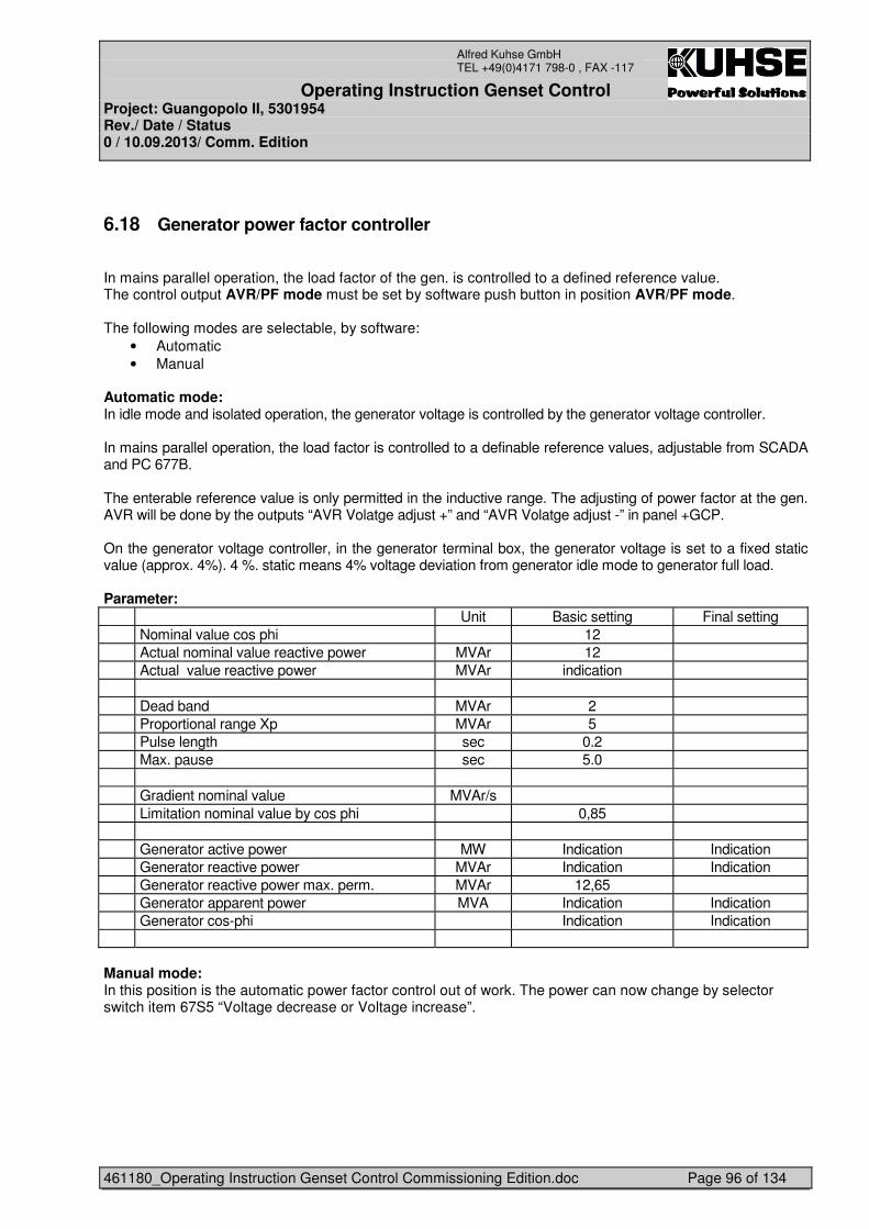
Operating Instruction Genset Control Project: Guangopolo II, 5301954 Rev./ Date / Status 0 / 10.09.2013/ Comm. Edition
461180_Operating Instruction Genset Control Commissioning Edition.doc Page 96 of 134
Alfred Kuhse GmbH TEL +49(0)4171 798-0 , FAX -117
6.18 Generator power factor controller
In mains parallel operation, the load factor of the gen. is controlled to a defined reference value. The control output AVR/PF mode must be set by software push button in position AVR/PF mode. The following modes are selectable, by software:
• Automatic • Manual
Automatic mode: In idle mode and isolated operation, the generator voltage is controlled by the generator voltage controller. In mains parallel operation, the load factor is controlled to a definable reference values, adjustable from SCADA and PC 677B. The enterable reference value is only permitted in the inductive range. The adjusting of power factor at the gen. AVR will be done by the outputs “AVR Volatge adjust +” and “AVR Volatge adjust -” in panel +GCP. On the generator voltage controller, in the generator terminal box, the generator voltage is set to a fixed static value (approx. 4%). 4 %. static means 4% voltage deviation from generator idle mode to generator full load. Parameter: Unit Basic setting Final setting Nominal value cos phi 12 Actual nominal value reactive power MVAr 12 Actual value reactive power MVAr indication Dead band MVAr 2 Proportional range Xp MVAr 5 Pulse length sec 0.2 Max. pause sec 5.0 Gradient nominal value MVAr/s Limitation nominal value by cos phi 0,85 Generator active power MW Indication Indication Generator reactive power MVAr Indication Indication Generator reactive power max. perm. MVAr 12,65 Generator apparent power MVA Indication Indication Generator cos-phi Indication Indication Manual mode: In this position is the automatic power factor control out of work. The power can now change by selector switch item 67S5 “Voltage decrease or Voltage increase”.
Operating Instruction Genset Control Project: Guangopolo II, 5301954 Rev./ Date / Status 0 / 10.09.2013/ Comm. Edition
461180_Operating Instruction Genset Control Commissioning Edition.doc Page 97 of 134
Alfred Kuhse GmbH TEL +49(0)4171 798-0 , FAX -117
6.19 Testing of shut down valve X-1SZV1012
Before the engine will start, the ttesting of shut down valve X-1SZV1012 is been done, as follow: 1. . Check of pressure switch 1PSH1012, it has to be activated. If no than comes the fault 111 “X-
1SZV1012 emergency stop valve fault”. 2. If item 1 is okay, de-energizing of X-1SZV1012 emergency stop valve 3. The pressure switch 1PSH1012 has to deactivated, if not the fault “Fault 111 “Engine Shutdown
Circuit Test Not Successful” comes. 4. After the test is not okay, the start is blocked. 5. After the test is okay, the test relay will be checked, if it isn’t okay the fault 108 “Failure Engine
Shutdown Valve Test Relay” will appears. 6. After the test is okay, the X-1SZV1012 emergency stop valve is energized and start released.
Operating Instruction Genset Control Project: Guangopolo II, 5301954 Rev./ Date / Status 0 / 10.09.2013/ Comm. Edition
461180_Operating Instruction Genset Control Commissioning Edition.doc Page 98 of 134
Alfred Kuhse GmbH TEL +49(0)4171 798-0 , FAX -117
6.20 CONTROL OF INTAKE AIR SYSTEM
6.20.1 Charge Air Blow-off System (xxMJQ61BR010/14)
The only active component of the blow-off system is the charge-air blow-off valve (xxMJQ62AA200) with electrical drive. Main components KKS-Code Reference document Blow-off valve xxMJQ62AA200 DRW 11.81031-0067 Blow-off valve feedback open xxMJQ62CG100 DRW 11.81031-0067 Blow-off valve feedback closed xxMJQ62CG120 DRW 11.81031-0067 Charge air blow-off valve: The charge air blow-off valve (xxMJQ62AA200) is controlled by the Plant Control System. The controllable electrical drive of the valve requires a 4-20 mA signal as command input. For a detailed interface description please see section Interfaces below and refer to the DEUFRA Manual for the electrical drive of type LE-10.
The sequence for the control of the valve shall be programmed in the following way:
Open valve after time delay of 10s,
IF
Intake air temperature xxMJQ61CT900 < 5°C (hysteresis ± 1°C)
AND
Charge air pressure > 2.3 bar (hysteresis for closing = - 0.3 bar)
OR (if charge air pressure not available)
Filling value > 75 % (hysteresis ± 5 %)
For malfunction check of charge air blow-off valve see section �o��.
Feedback of blow-off valve:
The blow-off valve is equipped with instrumentation for feedback of position OPEN and position CLOSED. Valve and feedback shall be displayed in SCADA.
• Interfaces For a detailed interface description refer to the DEUFRA manual for the electrical drive of type LE-10. Power Supply:
Power supply for the valve drive is 24V (DC).
Signals:
OPEN/CLOSED feedback is given as potential free contact.
Operating Instruction Genset Control Project: Guangopolo II, 5301954 Rev./ Date / Status 0 / 10.09.2013/ Comm. Edition
461180_Operating Instruction Genset Control Commissioning Edition.doc Page 99 of 134
Alfred Kuhse GmbH TEL +49(0)4171 798-0 , FAX -117
• Malfunction Malfunction check of charge air blow-off valve (xxMJQ62AA200): After opening the charge air blow-off valve, the charge air pressure must decrease by 0.1 bar within 10 seconds, compared to the charge air pressure before opening the valve. Otherwise the charge air blow-off valve has a malfunction. In case of malfunction of the valve an automatic load reduction of the engine shall be carried out and an error message shall be displayed.
• Alarms The process control system does not create any alarms from the feedback signals of the blow-off valve. Remote visualisation is only for indication of temperature.
• Start requirements Not applicable for blow-off system.
• Normal operation: manual local Not applicable for blow-off system.
• Normal operation: manual remote Not applicable for blow-off system.
• Normal operation: automatic remote Not applicable for blow-off system.
• Normal operation: automatic local Not applicable for blow-off system.
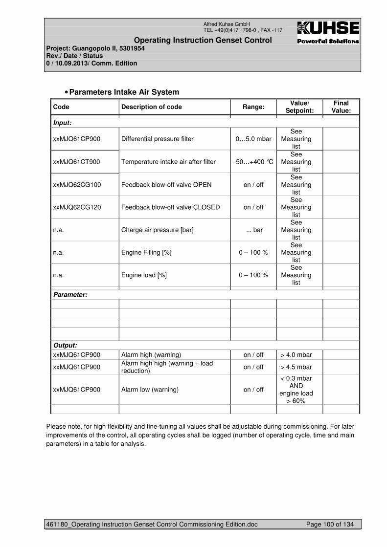
Operating Instruction Genset Control Project: Guangopolo II, 5301954 Rev./ Date / Status 0 / 10.09.2013/ Comm. Edition
461180_Operating Instruction Genset Control Commissioning Edition.doc Page 100 of 134
Alfred Kuhse GmbH TEL +49(0)4171 798-0 , FAX -117
• Parameters Intake Air System
Code Description of code Range: Value/ Setpoint:
Final Value:
Input:
xxMJQ61CP900 Differential pressure filter 0…5.0 mbar See
Measuring list
xxMJQ61CT900 Temperature intake air after filter -50…+400 °C See
Measuring list
xxMJQ62CG100 Feedback blow-off valve OPEN on / off See
Measuring list
xxMJQ62CG120 Feedback blow-off valve CLOSED on / off See
Measuring list
n.a. Charge air pressure [bar] ... bar See
Measuring list
n.a. Engine Filling [%] 0 – 100 % See
Measuring list
n.a. Engine load [%] 0 – 100 % See
Measuring list
Parameter:
Output: xxMJQ61CP900 Alarm high (warning) on / off > 4.0 mbar
xxMJQ61CP900 Alarm high high (warning + load reduction)
on / off > 4.5 mbar
xxMJQ61CP900 Alarm low (warning) on / off
< 0.3 mbar AND
engine load > 60%
Please note, for high flexibility and fine-tuning all values shall be adjustable during commissioning. For later improvements of the control, all operating cycles shall be logged (number of operating cycle, time and main parameters) in a table for analysis.
Operating Instruction Genset Control Project: Guangopolo II, 5301954 Rev./ Date / Status 0 / 10.09.2013/ Comm. Edition
461180_Operating Instruction Genset Control Commissioning Edition.doc Page 101 of 134
Alfred Kuhse GmbH TEL +49(0)4171 798-0 , FAX -117
6.20.2 General intake air instrumentation
The intake air module is equipped with instrumentation to indicate temperature of the intake air and pressure drop of the filter unit. Additionally, an emergency stop is available for modules that need to be entered for maintenance. Main components KKS-Code Reference document Temperature Transmitter xxMJQ61CT900 DRW 11.81031-0067 Differential pressure transmitter xxMJQ61CP900 DRW 11.81031-0067 Maintenance Switch for engine stop n.a. n.a. Intake air temperature: The temperature element (XXMJQ61CT900) is of PT100 type and indicates the temperature of the intake air after the air filter for the according engine. Connection type of the temperature element is 3-wire circuit. Its value is shown on SCADA / Panel PC. Furthermore it serves as input for the control of the charge air temperature control system (CHATCO). See functional description of cooling water system for more information.
Differential pressure (pocket filter):
The pocket filter unit (xxMJQ61AT012) is equipped with a differential pressure transmitter (xxMJQ61CP900). It provides an analogue signal (4-20 mA) for indication of the differential pressure of the filter. From this signal, the plant control system shall create several alarms in order to indicate the condition of the pocket filters. The alarms are defined in the section below. Maintenance Switch
The maintenance switch ensures safe conditions during maintenance works inside the module. When switched, it stops the running engine and/or blocks an engine restart.
• Interfaces For a detailed interface description see wiring diagram. Power Supply:
Power supply for general instrumentation elements is 24V (DC).
Signals:
Analogue signals are provided as 4…20 mA signal.
• Malfunction No functional protection against malfunction. Wire-break detection is available.
Operating Instruction Genset Control Project: Guangopolo II, 5301954 Rev./ Date / Status 0 / 10.09.2013/ Comm. Edition
461180_Operating Instruction Genset Control Commissioning Edition.doc Page 102 of 134
Alfred Kuhse GmbH TEL +49(0)4171 798-0 , FAX -117
• Alarms The signals are transmitted to the plant control system, where they shall be processed in the following way: Argument definition KKS-Code Range Value Action If diff. pressure xxMJQ61CP900 < 0.3 mbar low show alarm L AND engine load n.a. > 60% If diff. pressure xxMJQ61CP900 > 4.0 mbar high show alarm H If diff. pressure xxMJQ61CP900 > 4.5 mbar high high show alarm HH, load red. to 60 % The process control system does not create any alarms from the temperature sensor. Remote visualisation is only for indication of temperature.
• Start requirements Filters must be in position and good condition. Differential pressure must be below Alarm H.
• Normal operation: manual local Not applicable for dry filters.
• Normal operation: manual remote Not applicable for dry filters.
• Normal operation: automatic remote Not applicable for dry filters.
• Normal operation: automatic local Not applicable for dry filters.
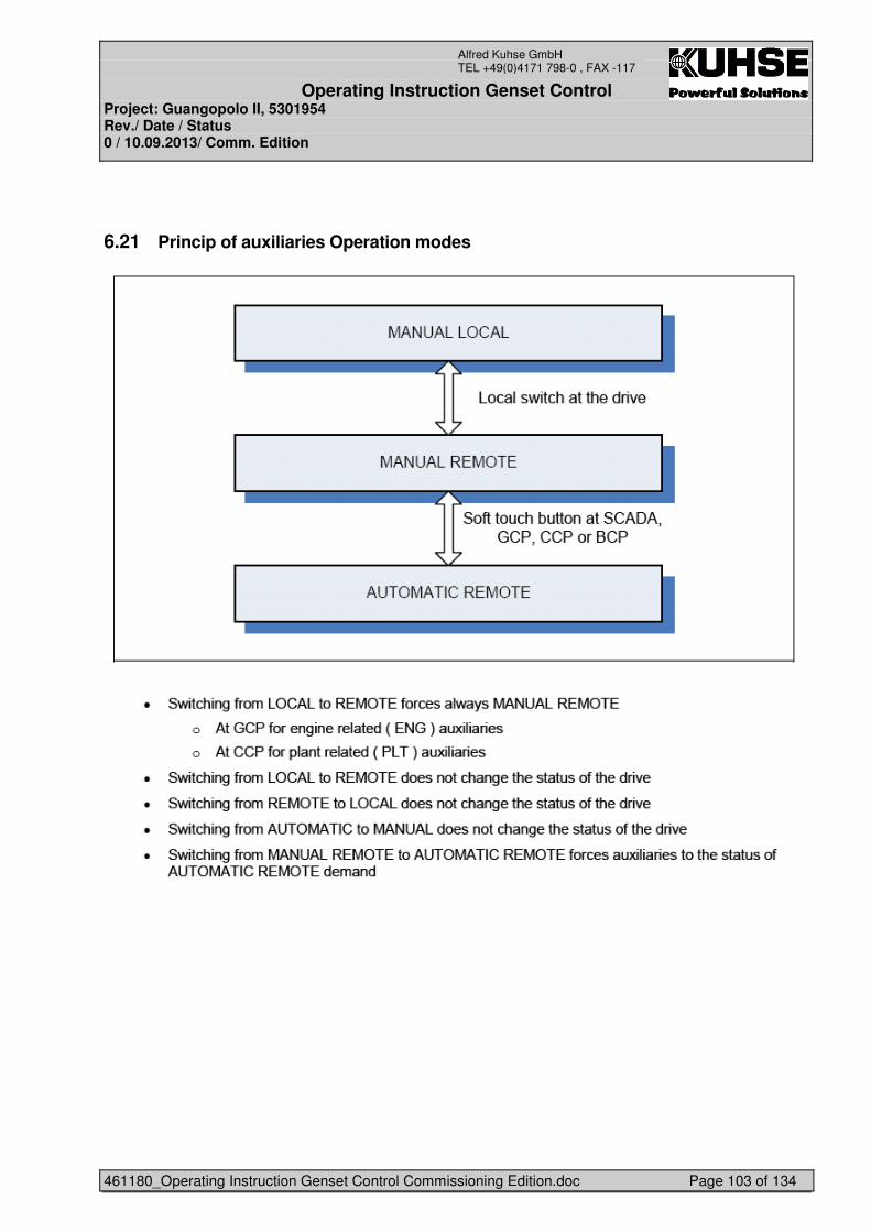
Operating Instruction Genset Control Project: Guangopolo II, 5301954 Rev./ Date / Status 0 / 10.09.2013/ Comm. Edition
461180_Operating Instruction Genset Control Commissioning Edition.doc Page 103 of 134
Alfred Kuhse GmbH TEL +49(0)4171 798-0 , FAX -117
6.21 Princip of auxiliaries Operation modes
Operating Instruction Genset Control Project: Guangopolo II, 5301954 Rev./ Date / Status 0 / 10.09.2013/ Comm. Edition
461180_Operating Instruction Genset Control Commissioning Edition.doc Page 104 of 134
Alfred Kuhse GmbH TEL +49(0)4171 798-0 , FAX -117
6.21.1 Manual Local Mode Auxiliary Drives
Operating Instruction Genset Control Project: Guangopolo II, 5301954 Rev./ Date / Status 0 / 10.09.2013/ Comm. Edition
461180_Operating Instruction Genset Control Commissioning Edition.doc Page 105 of 134
Alfred Kuhse GmbH TEL +49(0)4171 798-0 , FAX -117
6.21.2 Manual Remote Mode Auxiliary Drives
Operating Instruction Genset Control Project: Guangopolo II, 5301954 Rev./ Date / Status 0 / 10.09.2013/ Comm. Edition
461180_Operating Instruction Genset Control Commissioning Edition.doc Page 106 of 134
Alfred Kuhse GmbH TEL +49(0)4171 798-0 , FAX -117
6.21.3 Automatic Remote Mode Auxiliary Drives
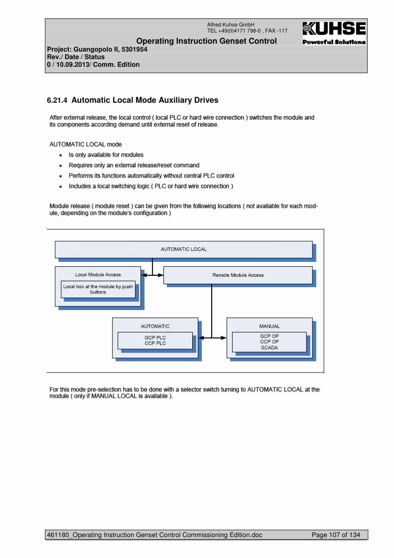
Operating Instruction Genset Control Project: Guangopolo II, 5301954 Rev./ Date / Status 0 / 10.09.2013/ Comm. Edition
461180_Operating Instruction Genset Control Commissioning Edition.doc Page 107 of 134
Alfred Kuhse GmbH TEL +49(0)4171 798-0 , FAX -117
6.21.4 Automatic Local Mode Auxiliary Drives
Operating Instruction Genset Control Project: Guangopolo II, 5301954 Rev./ Date / Status 0 / 10.09.2013/ Comm. Edition
461180_Operating Instruction Genset Control Commissioning Edition.doc Page 108 of 134
Alfred Kuhse GmbH TEL +49(0)4171 798-0 , FAX -117
6.21.5 Double pumps
Operating Instruction Genset Control Project: Guangopolo II, 5301954 Rev./ Date / Status 0 / 10.09.2013/ Comm. Edition
461180_Operating Instruction Genset Control Commissioning Edition.doc Page 109 of 134
Alfred Kuhse GmbH TEL +49(0)4171 798-0 , FAX -117
6.21.6 Manual pump switching
6.21.7 Double Starter Pumps, Master Selection Philosophy
Selection of master pump shall be possible in two modes activated for AUTO REMOTE:
1. Master pump selection by operator 2. Master pump selection by operating hours
The operator shall select between the two modes. Location: Panel PC at CCP (if selector switch at CCP is in „CCP“-position) and from SCADA (if selector switch at CCP is in „SCADA“-position). Double starter faceplate with two buttons select “Operator Master Selection” and “Master Selection by Operating Hours”. Selected mode shall be indicated. General: THE PUMP WHICH IS RUNNING IS THE MASTER PUMP. IT IS NEVER THE STANDBY
PUMP WHICH IS RUNNING ALONE. A pump which is disturbed cannot be selected as master. If one or both pumps are disturbed no selection of mode for master selection or
master is possible. Operating hours criteria:
Operating hours as the criteria for master shall only be considered for the next AUTO start of the pumps, not during running pumps.
If pumps are in REMOTE MANUAL, the operator can between selection by operator or by operating hours if pumps are running or standstill. The operator can change the master only if both pumps are running or standstill.
Default by PLC Start: Pump 1 is master, master pump selection by operator. Each selection causes an event. Description:
Scenario 1: Pumps standstill and in REMOTE AUTO. Operator selects “Master pump selection by operator” (if not already selected) Operator selects pump 1 as master. If automatic request start of one pump, pump 1 will start.
Operating Instruction Genset Control Project: Guangopolo II, 5301954 Rev./ Date / Status 0 / 10.09.2013/ Comm. Edition
461180_Operating Instruction Genset Control Commissioning Edition.doc Page 110 of 134
Alfred Kuhse GmbH TEL +49(0)4171 798-0 , FAX -117
or Operator selects pump 2 as master. If automatic request start of one pump, pump 2 will start. Scenario 2: Pumps standstill and in REMOTE AUTO. Operator selects “Master pump selection by operating hours” (if not already selected) Pump 1 has less operating hours than pump 2. If automatic request start of one pump, pump
1 will start. or Pump 2 has less operating hours than pump 1. If automatic request start of one pump, pump
2 will start.
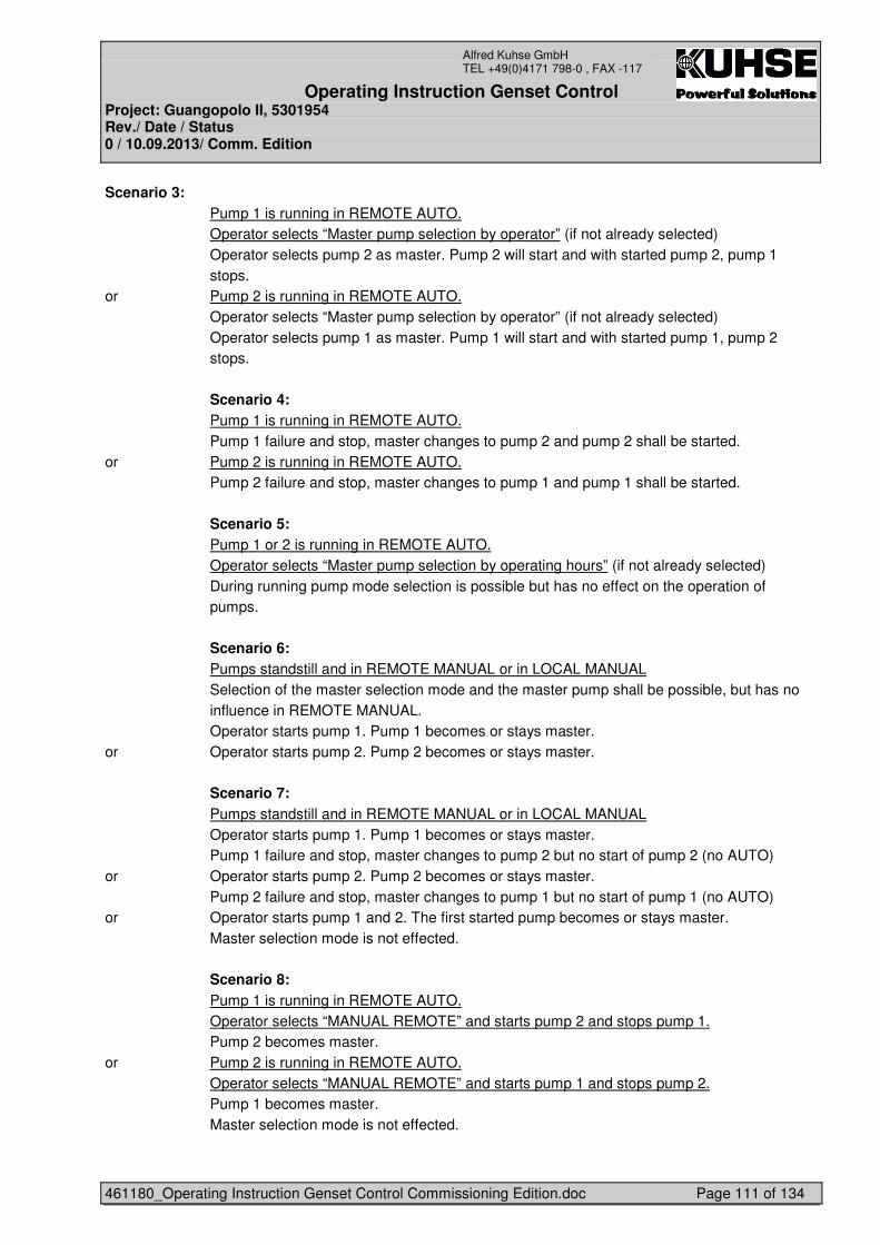
Operating Instruction Genset Control Project: Guangopolo II, 5301954 Rev./ Date / Status 0 / 10.09.2013/ Comm. Edition
461180_Operating Instruction Genset Control Commissioning Edition.doc Page 111 of 134
Alfred Kuhse GmbH TEL +49(0)4171 798-0 , FAX -117
Scenario 3: Pump 1 is running in REMOTE AUTO. Operator selects “Master pump selection by operator” (if not already selected) Operator selects pump 2 as master. Pump 2 will start and with started pump 2, pump 1
stops. or Pump 2 is running in REMOTE AUTO. Operator selects “Master pump selection by operator” (if not already selected) Operator selects pump 1 as master. Pump 1 will start and with started pump 1, pump 2
stops. Scenario 4: Pump 1 is running in REMOTE AUTO. Pump 1 failure and stop, master changes to pump 2 and pump 2 shall be started. or Pump 2 is running in REMOTE AUTO. Pump 2 failure and stop, master changes to pump 1 and pump 1 shall be started. Scenario 5: Pump 1 or 2 is running in REMOTE AUTO. Operator selects “Master pump selection by operating hours” (if not already selected) During running pump mode selection is possible but has no effect on the operation of
pumps. Scenario 6: Pumps standstill and in REMOTE MANUAL or in LOCAL MANUAL Selection of the master selection mode and the master pump shall be possible, but has no
influence in REMOTE MANUAL. Operator starts pump 1. Pump 1 becomes or stays master.
or Operator starts pump 2. Pump 2 becomes or stays master. Scenario 7: Pumps standstill and in REMOTE MANUAL or in LOCAL MANUAL Operator starts pump 1. Pump 1 becomes or stays master. Pump 1 failure and stop, master changes to pump 2 but no start of pump 2 (no AUTO) or Operator starts pump 2. Pump 2 becomes or stays master. Pump 2 failure and stop, master changes to pump 1 but no start of pump 1 (no AUTO) or Operator starts pump 1 and 2. The first started pump becomes or stays master. Master selection mode is not effected. Scenario 8: Pump 1 is running in REMOTE AUTO. Operator selects “MANUAL REMOTE” and starts pump 2 and stops pump 1. Pump 2 becomes master. or Pump 2 is running in REMOTE AUTO. Operator selects “MANUAL REMOTE” and starts pump 1 and stops pump 2. Pump 1 becomes master. Master selection mode is not effected.
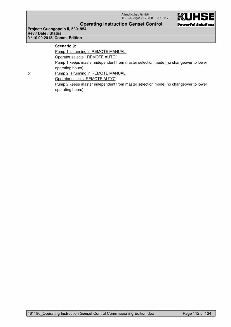
Operating Instruction Genset Control Project: Guangopolo II, 5301954 Rev./ Date / Status 0 / 10.09.2013/ Comm. Edition
461180_Operating Instruction Genset Control Commissioning Edition.doc Page 112 of 134
Alfred Kuhse GmbH TEL +49(0)4171 798-0 , FAX -117
Scenario 9: Pump 1 is running in REMOTE MANUAL. Operator selects “ REMOTE AUTO” Pump 1 keeps master independent from master selection mode (no changeover to lower
operating hours). or Pump 2 is running in REMOTE MANUAL. Operator selects REMOTE AUTO” Pump 2 keeps master independent from master selection mode (no changeover to lower
operating hours).
Operating Instruction Genset Control Project: Guangopolo II, 5301954 Rev./ Date / Status 0 / 10.09.2013/ Comm. Edition
461180_Operating Instruction Genset Control Commissioning Edition.doc Page 113 of 134
Alfred Kuhse GmbH TEL +49(0)4171 798-0 , FAX -117
7 LV ENGINE AUXILIARIES PANEL +EAPX
These panels contain the power components for the motor auxiliaries and the data interface to the appropriate ECPx panel and stands in the mechanical annex.
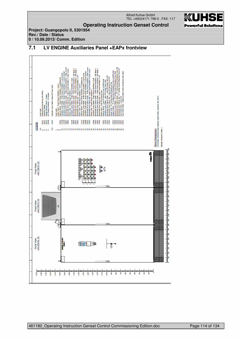
Operating Instruction Genset Control Project: Guangopolo II, 5301954 Rev./ Date / Status 0 / 10.09.2013/ Comm. Edition
461180_Operating Instruction Genset Control Commissioning Edition.doc Page 114 of 134
Alfred Kuhse GmbH TEL +49(0)4171 798-0 , FAX -117
7.1 LV ENGINE Auxiliaries Panel +EAPx frontview
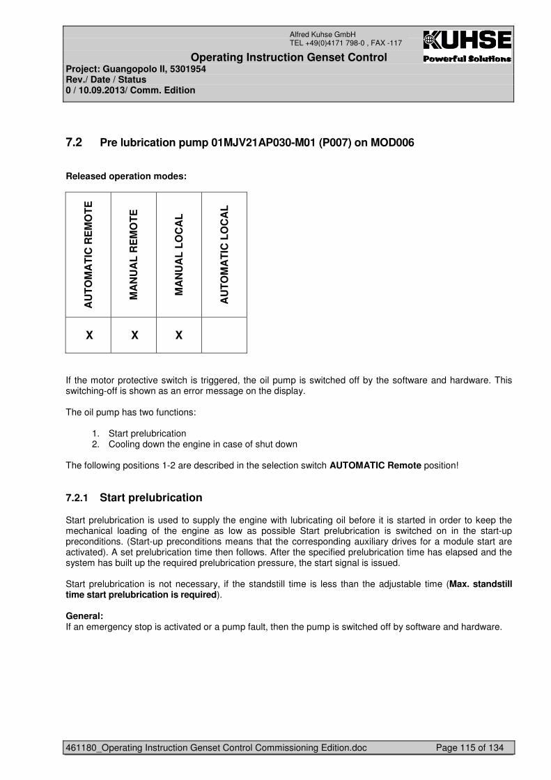
Operating Instruction Genset Control Project: Guangopolo II, 5301954 Rev./ Date / Status 0 / 10.09.2013/ Comm. Edition
461180_Operating Instruction Genset Control Commissioning Edition.doc Page 115 of 134
Alfred Kuhse GmbH TEL +49(0)4171 798-0 , FAX -117
7.2 Pre lubrication pump 01MJV21AP030-M01 (P007) on MOD006
Released operation modes:
AU
TO
MA
TIC
RE
MO
TE
MA
NU
AL
RE
MO
TE
MA
NU
AL
LO
CA
L
AU
TO
MA
TIC
LO
CA
L
X X X
If the motor protective switch is triggered, the oil pump is switched off by the software and hardware. This switching-off is shown as an error message on the display. The oil pump has two functions:
1. Start prelubrication 2. Cooling down the engine in case of shut down
The following positions 1-2 are described in the selection switch AUTOMATIC Remote position!
7.2.1 Start prelubrication
Start prelubrication is used to supply the engine with lubricating oil before it is started in order to keep the mechanical loading of the engine as low as possible Start prelubrication is switched on in the start-up preconditions. (Start-up preconditions means that the corresponding auxiliary drives for a module start are activated). A set prelubrication time then follows. After the specified prelubrication time has elapsed and the system has built up the required prelubrication pressure, the start signal is issued. Start prelubrication is not necessary, if the standstill time is less than the adjustable time (Max. standstill time start prelubrication is required). General: If an emergency stop is activated or a pump fault, then the pump is switched off by software and hardware.
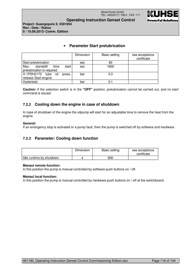
Operating Instruction Genset Control Project: Guangopolo II, 5301954 Rev./ Date / Status 0 / 10.09.2013/ Comm. Edition
461180_Operating Instruction Genset Control Commissioning Edition.doc Page 116 of 134
Alfred Kuhse GmbH TEL +49(0)4171 798-0 , FAX -117
• Parameter Start prelubrication Dimension Basic setting see acceptance
certificate Start prelubrication sec 60 Max. standstill time start prelubrication is required
sec 1800
X-1PSH2170 lube oil press. release Start engine
bar 0.3
Hysteresis bar 0.1 Caution: If the selection switch is in the "OFF" position, prelubrication cannot be carried out, and no start command is issued.
7.2.2 Cooling down the engine in case of shutdown
In case of shutdown of the engine the oilpump will start for an adjustable time to remove the heat from the engine. General: If an emergency stop is activated or a pump fault, then the pump is switched off by software and hardware.
7.2.3 Parameter: Cooling down function
Dimension Basic setting see acceptance
certificate Idle runtime by shutdown s 600 Manaul remote function: In this position the pump is manual controlled by software push buttons on / off. Manaul local function: In this position the pump is manual controlled by hardware push buttons on / off at the switchboard.
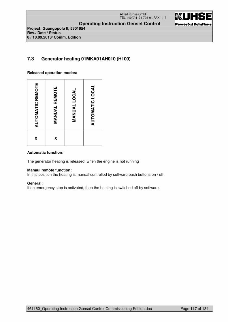
Operating Instruction Genset Control Project: Guangopolo II, 5301954 Rev./ Date / Status 0 / 10.09.2013/ Comm. Edition
461180_Operating Instruction Genset Control Commissioning Edition.doc Page 117 of 134
Alfred Kuhse GmbH TEL +49(0)4171 798-0 , FAX -117
7.3 Generator heating 01MKA01AH010 (H100)
Released operation modes:
AU
TO
MA
TIC
RE
MO
TE
MA
NU
AL
RE
MO
TE
MA
NU
AL
LO
CA
L
AU
TO
MA
TIC
LO
CA
L
X X
Automatic function: The generator heating is released, when the engine is not running Manaul remote function: In this position the heating is manual controlled by software push buttons on / off. General: If an emergency stop is activated, then the heating is switched off by software.
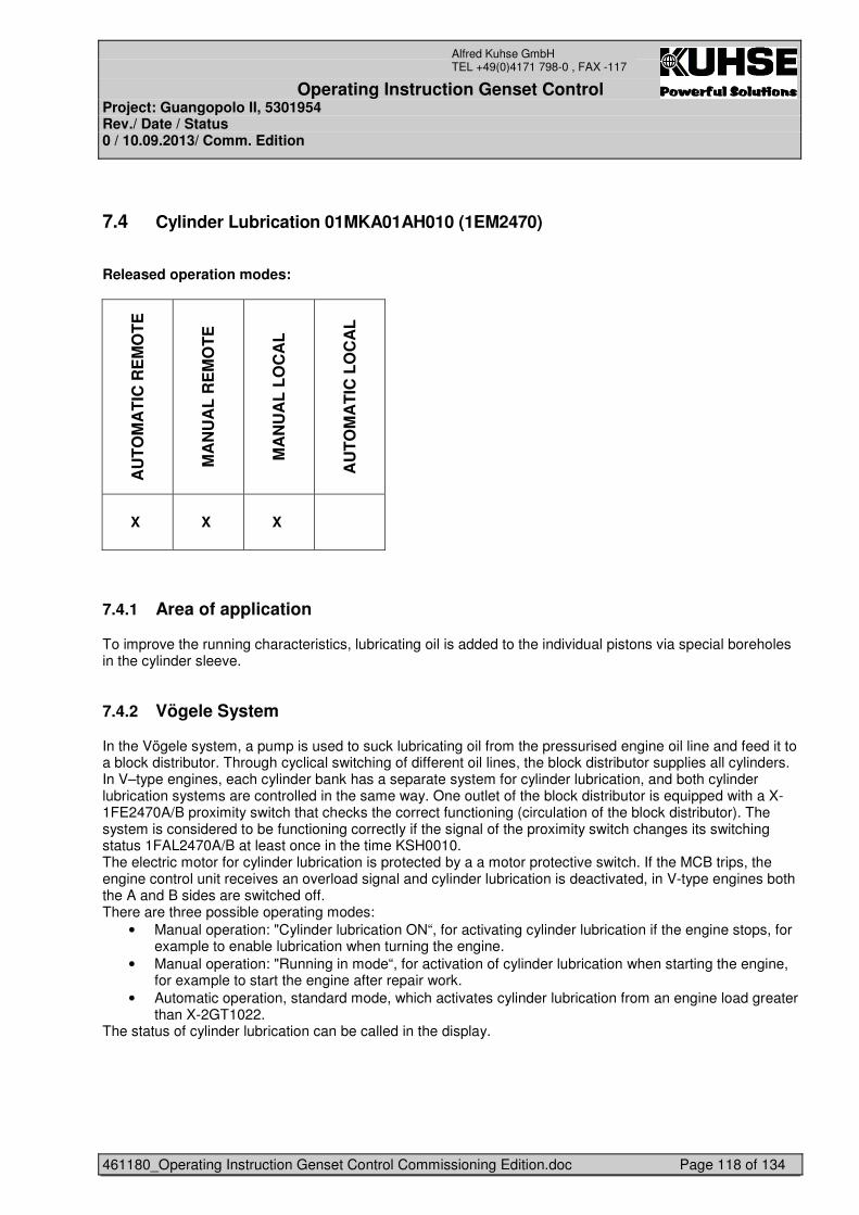
Operating Instruction Genset Control Project: Guangopolo II, 5301954 Rev./ Date / Status 0 / 10.09.2013/ Comm. Edition
461180_Operating Instruction Genset Control Commissioning Edition.doc Page 118 of 134
Alfred Kuhse GmbH TEL +49(0)4171 798-0 , FAX -117
7.4 Cylinder Lubrication 01MKA01AH010 (1EM2470)
Released operation modes:
AU
TO
MA
TIC
RE
MO
TE
MA
NU
AL
RE
MO
TE
MA
NU
AL
LO
CA
L
AU
TO
MA
TIC
LO
CA
L
X X X
7.4.1 Area of application
To improve the running characteristics, lubricating oil is added to the individual pistons via special boreholes in the cylinder sleeve.
7.4.2 Vögele System
In the Vögele system, a pump is used to suck lubricating oil from the pressurised engine oil line and feed it to a block distributor. Through cyclical switching of different oil lines, the block distributor supplies all cylinders. In V–type engines, each cylinder bank has a separate system for cylinder lubrication, and both cylinder lubrication systems are controlled in the same way. One outlet of the block distributor is equipped with a X-1FE2470A/B proximity switch that checks the correct functioning (circulation of the block distributor). The system is considered to be functioning correctly if the signal of the proximity switch changes its switching status 1FAL2470A/B at least once in the time KSH0010. The electric motor for cylinder lubrication is protected by a a motor protective switch. If the MCB trips, the engine control unit receives an overload signal and cylinder lubrication is deactivated, in V-type engines both the A and B sides are switched off. There are three possible operating modes:
• Manual operation: "Cylinder lubrication ON“, for activating cylinder lubrication if the engine stops, for example to enable lubrication when turning the engine.
• Manual operation: "Running in mode“, for activation of cylinder lubrication when starting the engine, for example to start the engine after repair work.
• Automatic operation, standard mode, which activates cylinder lubrication from an engine load greater than X-2GT1022.
The status of cylinder lubrication can be called in the display.
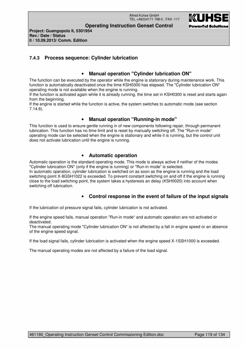
Operating Instruction Genset Control Project: Guangopolo II, 5301954 Rev./ Date / Status 0 / 10.09.2013/ Comm. Edition
461180_Operating Instruction Genset Control Commissioning Edition.doc Page 119 of 134
Alfred Kuhse GmbH TEL +49(0)4171 798-0 , FAX -117
7.4.3 Process sequence: Cylinder lubrication
• Manual operation "Cylinder lubrication ON" The function can be executed by the operator while the engine is stationary during maintenance work. This function is automatically deactivated once the time KSH0300 has elapsed. The "Cylinder lubrication ON" operating mode is not available when the engine is running. If the function is activated again while it is already running, the time set in KSH0300 is reset and starts again from the beginning. If the engine is started while the function is active, the system switches to automatic mode (see section 7.14.6).
• Manual operation "Running-in mode" This function is used to ensure gentle running in of new components following repair, through permanent lubrication. This function has no time limit and is reset by manually switching off. The "Run-in mode“ operating mode can be selected when the engine is stationary and while it is running, but the control unit does not activate lubrication until the engine is running.
• Automatic operation Automatic operation is the standard operating mode. This mode is always active if neither of the modes "Cylinder lubrication ON" (only if the engine is running) or "Run-in mode“ is selected. In automatic operation, cylinder lubrication is switched on as soon as the engine is running and the load switching point X-8GSH1022 is exceeded. To prevent constant switching on and off if the engine is running close to the load switching point, the system takes a hysteresis an delay (KSH0020) into account when switching off lubrication.
• Control response in the event of failure of the input signals If the lubrication oil pressure signal fails, cylinder lubrication is not activated. If the engine speed fails, manual operation "Run-in mode“ and automatic operation are not activated or deactivated. The manual operating mode "Cylinder lubrication ON“ is not affected by a fall in engine speed or an absence of the engine speed signal. If the load signal fails, cylinder lubrication is activated when the engine speed X-1SSH1000 is exceeded. The manual operating modes are not affected by a failure of the load signal.
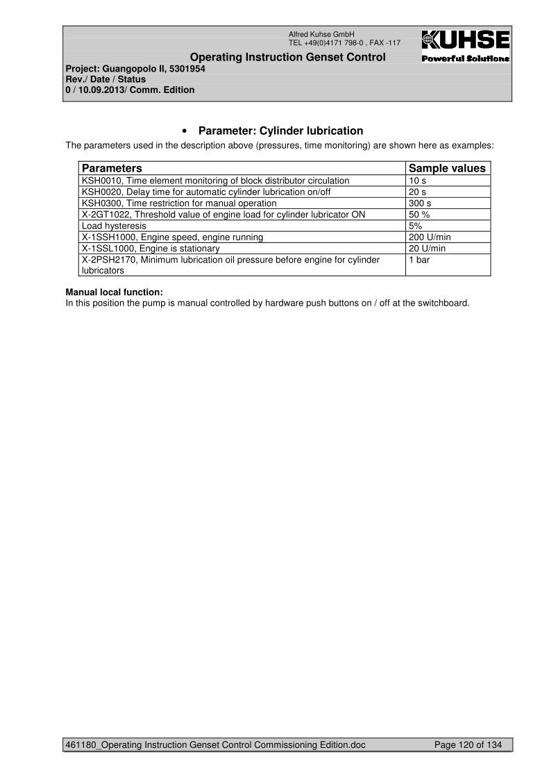
Operating Instruction Genset Control Project: Guangopolo II, 5301954 Rev./ Date / Status 0 / 10.09.2013/ Comm. Edition
461180_Operating Instruction Genset Control Commissioning Edition.doc Page 120 of 134
Alfred Kuhse GmbH TEL +49(0)4171 798-0 , FAX -117
• Parameter: Cylinder lubrication The parameters used in the description above (pressures, time monitoring) are shown here as examples:
Parameters Sample values KSH0010, Time element monitoring of block distributor circulation 10 s KSH0020, Delay time for automatic cylinder lubrication on/off 20 s KSH0300, Time restriction for manual operation 300 s X-2GT1022, Threshold value of engine load for cylinder lubricator ON 50 % Load hysteresis 5% X-1SSH1000, Engine speed, engine running 200 U/min X-1SSL1000, Engine is stationary 20 U/min X-2PSH2170, Minimum lubrication oil pressure before engine for cylinder lubricators
1 bar
Manual local function: In this position the pump is manual controlled by hardware push buttons on / off at the switchboard.
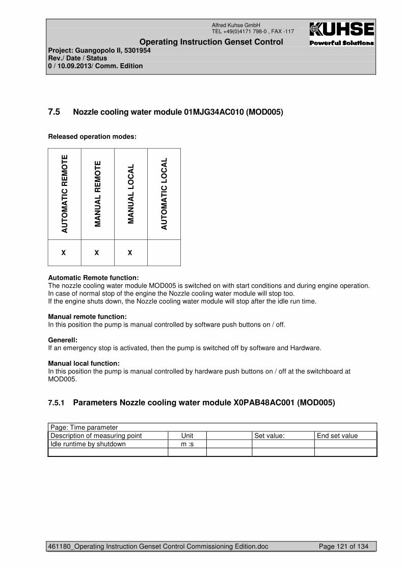
Operating Instruction Genset Control Project: Guangopolo II, 5301954 Rev./ Date / Status 0 / 10.09.2013/ Comm. Edition
461180_Operating Instruction Genset Control Commissioning Edition.doc Page 121 of 134
Alfred Kuhse GmbH TEL +49(0)4171 798-0 , FAX -117
7.5 Nozzle cooling water module 01MJG34AC010 (MOD005)
Released operation modes:
AU
TO
MA
TIC
RE
MO
TE
MA
NU
AL
RE
MO
TE
MA
NU
AL
LO
CA
L
AU
TO
MA
TIC
LO
CA
L
X X X
Automatic Remote function: The nozzle cooling water module MOD005 is switched on with start conditions and during engine operation. In case of normal stop of the engine the Nozzle cooling water module will stop too. If the engine shuts down, the Nozzle cooling water module will stop after the idle run time. Manual remote function: In this position the pump is manual controlled by software push buttons on / off. Generell: If an emergency stop is activated, then the pump is switched off by software and Hardware. Manual local function: In this position the pump is manual controlled by hardware push buttons on / off at the switchboard at MOD005.
7.5.1 Parameters Nozzle cooling water module X0PAB48AC001 (MOD005)
Page: Time parameter Description of measuring point Unit Set value: End set value Idle runtime by shutdown m :s
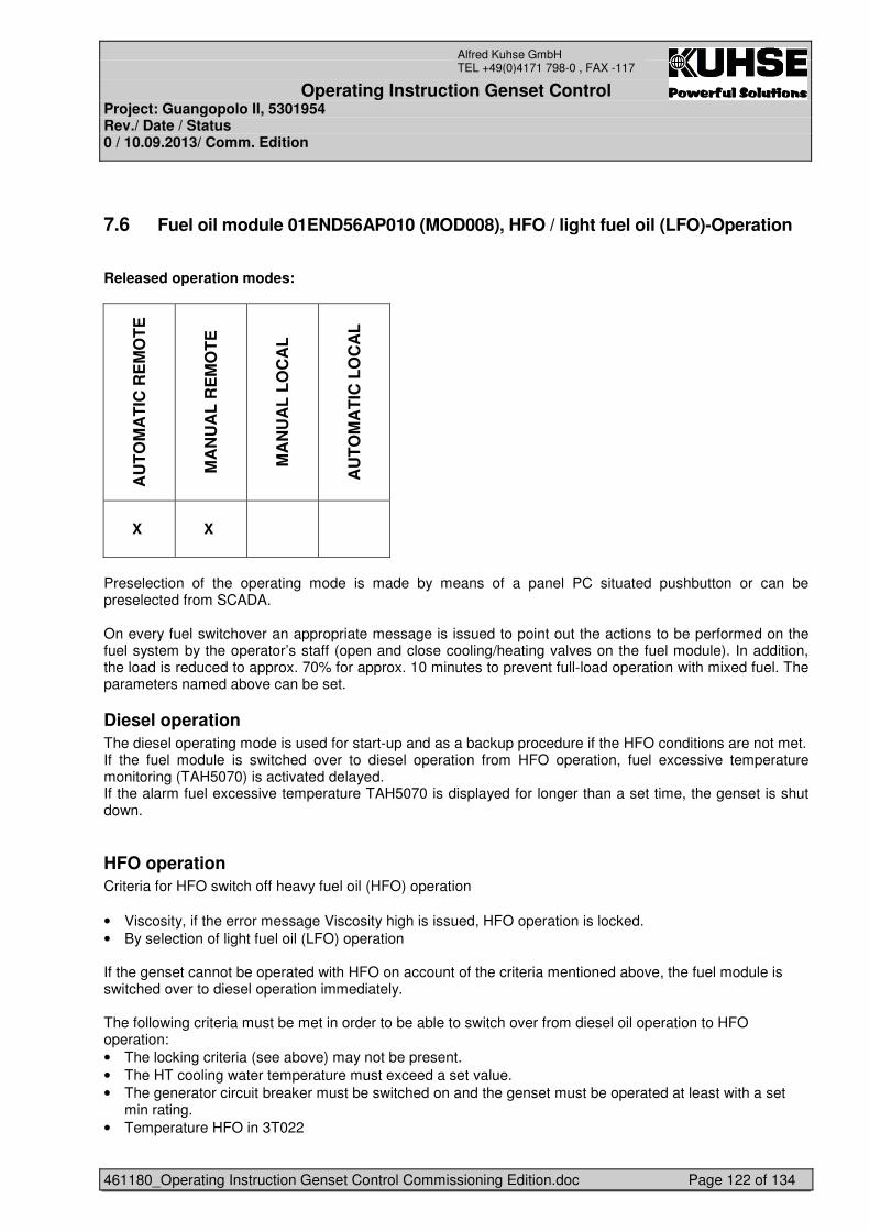
Operating Instruction Genset Control Project: Guangopolo II, 5301954 Rev./ Date / Status 0 / 10.09.2013/ Comm. Edition
461180_Operating Instruction Genset Control Commissioning Edition.doc Page 122 of 134
Alfred Kuhse GmbH TEL +49(0)4171 798-0 , FAX -117
7.6 Fuel oil module 01END56AP010 (MOD008), HFO / light fuel oil (LFO)-Operation
Released operation modes:
AU
TO
MA
TIC
RE
MO
TE
MA
NU
AL
RE
MO
TE
MA
NU
AL
LO
CA
L
AU
TO
MA
TIC
LO
CA
L
X X
Preselection of the operating mode is made by means of a panel PC situated pushbutton or can be preselected from SCADA. On every fuel switchover an appropriate message is issued to point out the actions to be performed on the fuel system by the operator’s staff (open and close cooling/heating valves on the fuel module). In addition, the load is reduced to approx. 70% for approx. 10 minutes to prevent full-load operation with mixed fuel. The parameters named above can be set.
Diesel operation The diesel operating mode is used for start-up and as a backup procedure if the HFO conditions are not met. If the fuel module is switched over to diesel operation from HFO operation, fuel excessive temperature monitoring (TAH5070) is activated delayed. If the alarm fuel excessive temperature TAH5070 is displayed for longer than a set time, the genset is shut down.
HFO operation Criteria for HFO switch off heavy fuel oil (HFO) operation • Viscosity, if the error message Viscosity high is issued, HFO operation is locked. • By selection of light fuel oil (LFO) operation If the genset cannot be operated with HFO on account of the criteria mentioned above, the fuel module is switched over to diesel operation immediately. The following criteria must be met in order to be able to switch over from diesel oil operation to HFO operation: • The locking criteria (see above) may not be present. • The HT cooling water temperature must exceed a set value. • The generator circuit breaker must be switched on and the genset must be operated at least with a set
min rating. • Temperature HFO in 3T022
Operating Instruction Genset Control Project: Guangopolo II, 5301954 Rev./ Date / Status 0 / 10.09.2013/ Comm. Edition
461180_Operating Instruction Genset Control Commissioning Edition.doc Page 123 of 134
Alfred Kuhse GmbH TEL +49(0)4171 798-0 , FAX -117
• Steam pressure in 1PTT032 If the criteria above are met, the fuel module is switched over to HFO operation. During switchover monitoring of the fuel pressure (PAL5070) is deactivated for 3 seconds in order to suppress the triggering of switchover-related pressure fluctuations. In HFO operation the monitoring of excessive fuel temperature (TAH5070) is deactivated. For switchover viscosity monitoring is suppressed for a set time in order to bridge control fluctuations. An absolute viscosity limit, which is always monitored, is still active. If the system is shut down on fault from HFO operation, the auxiliary drives which are relevant for HFO operation are requested constantly and are not shut down after the set idle run time. If, however, the load on the genset is reduced when it is operational and is deselected, diesel operation is activated as the first action. Manual remote function: In this position the valves are manual controlled by software push buttons HFO / LFO.
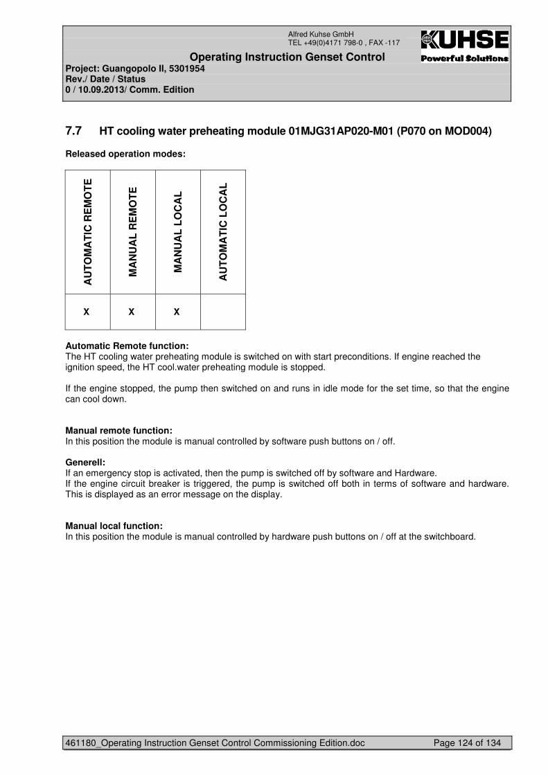
Operating Instruction Genset Control Project: Guangopolo II, 5301954 Rev./ Date / Status 0 / 10.09.2013/ Comm. Edition
461180_Operating Instruction Genset Control Commissioning Edition.doc Page 124 of 134
Alfred Kuhse GmbH TEL +49(0)4171 798-0 , FAX -117
7.7 HT cooling water preheating module 01MJG31AP020-M01 (P070 on MOD004)
Released operation modes:
AU
TO
MA
TIC
RE
MO
TE
MA
NU
AL
RE
MO
TE
MA
NU
AL
LO
CA
L
AU
TO
MA
TIC
LO
CA
L
X X X
Automatic Remote function: The HT cooling water preheating module is switched on with start preconditions. If engine reached the ignition speed, the HT cool.water preheating module is stopped. If the engine stopped, the pump then switched on and runs in idle mode for the set time, so that the engine can cool down. Manual remote function: In this position the module is manual controlled by software push buttons on / off. Generell: If an emergency stop is activated, then the pump is switched off by software and Hardware. If the engine circuit breaker is triggered, the pump is switched off both in terms of software and hardware. This is displayed as an error message on the display. Manual local function: In this position the module is manual controlled by hardware push buttons on / off at the switchboard.
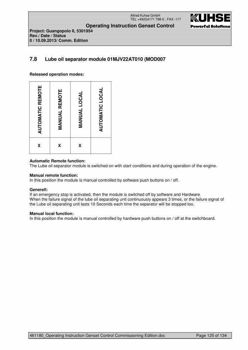
Operating Instruction Genset Control Project: Guangopolo II, 5301954 Rev./ Date / Status 0 / 10.09.2013/ Comm. Edition
461180_Operating Instruction Genset Control Commissioning Edition.doc Page 125 of 134
Alfred Kuhse GmbH TEL +49(0)4171 798-0 , FAX -117
7.8 Lube oil separator module 01MJV22AT010 (MOD007
Released operation modes:
AU
TO
MA
TIC
RE
MO
TE
MA
NU
AL
RE
MO
TE
MA
NU
AL
LO
CA
L
AU
TO
MA
TIC
LO
CA
L
X X X
Automatic Remote function: The Lube oil separator module is switched on with start conditions and during operation of the engine. Manual remote function: In this position the module is manual controlled by software push buttons on / off. Generell: If an emergency stop is activated, then the module is switched off by software and Hardware. When the failure signal of the lube oil separating unit continuously appears 3 times, or the failure signal of the Lube oil separating unit lasts 10 Seconds each time the separator will be stopped too. Manual local function: In this position the module is manual controlled by hardware push buttons on / off at the switchboard.
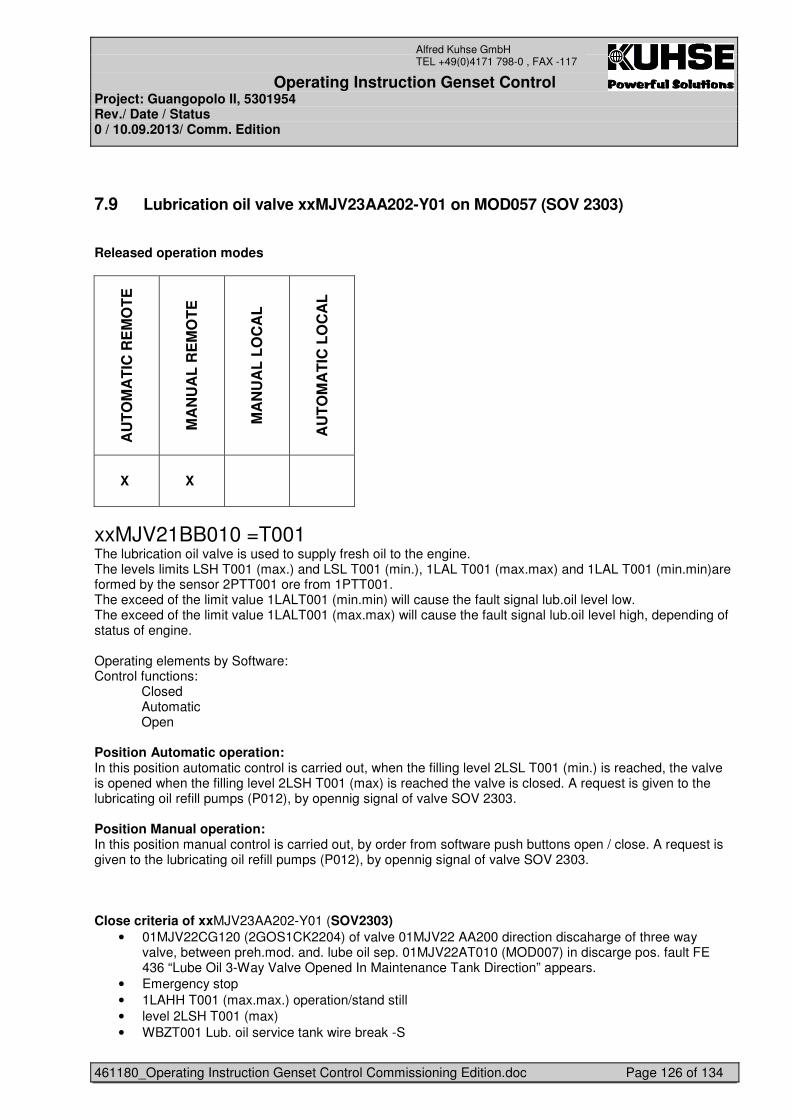
Operating Instruction Genset Control Project: Guangopolo II, 5301954 Rev./ Date / Status 0 / 10.09.2013/ Comm. Edition
461180_Operating Instruction Genset Control Commissioning Edition.doc Page 126 of 134
Alfred Kuhse GmbH TEL +49(0)4171 798-0 , FAX -117
7.9 Lubrication oil valve xxMJV23AA202-Y01 on MOD057 (SOV 2303)
Released operation modes
AU
TO
MA
TIC
RE
MO
TE
MA
NU
AL
RE
MO
TE
MA
NU
AL
LO
CA
L
AU
TO
MA
TIC
LO
CA
L
X X
xxMJV21BB010 =T001 The lubrication oil valve is used to supply fresh oil to the engine. The levels limits LSH T001 (max.) and LSL T001 (min.), 1LAL T001 (max.max) and 1LAL T001 (min.min)are formed by the sensor 2PTT001 ore from 1PTT001. The exceed of the limit value 1LALT001 (min.min) will cause the fault signal lub.oil level low. The exceed of the limit value 1LALT001 (max.max) will cause the fault signal lub.oil level high, depending of status of engine. Operating elements by Software: Control functions:
Closed Automatic Open
Position Automatic operation: In this position automatic control is carried out, when the filling level 2LSL T001 (min.) is reached, the valve is opened when the filling level 2LSH T001 (max) is reached the valve is closed. A request is given to the lubricating oil refill pumps (P012), by opennig signal of valve SOV 2303. Position Manual operation: In this position manual control is carried out, by order from software push buttons open / close. A request is given to the lubricating oil refill pumps (P012), by opennig signal of valve SOV 2303. Close criteria of xxMJV23AA202-Y01 (SOV2303)
• 01MJV22CG120 (2GOS1CK2204) of valve 01MJV22 AA200 direction discaharge of three way valve, between preh.mod. and. lube oil sep. 01MJV22AT010 (MOD007) in discarge pos. fault FE 436 “Lube Oil 3-Way Valve Opened In Maintenance Tank Direction” appears.
• Emergency stop • 1LAHH T001 (max.max.) operation/stand still • level 2LSH T001 (max) • WBZT001 Lub. oil service tank wire break -S
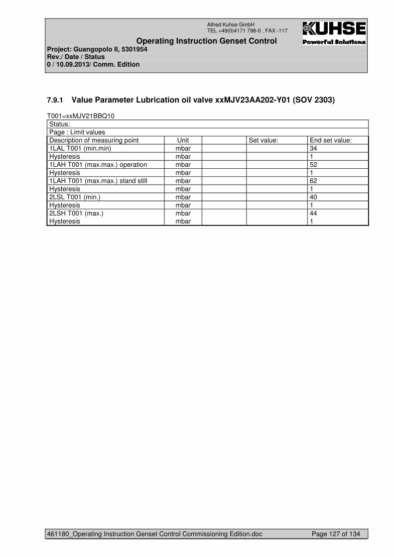
Operating Instruction Genset Control Project: Guangopolo II, 5301954 Rev./ Date / Status 0 / 10.09.2013/ Comm. Edition
461180_Operating Instruction Genset Control Commissioning Edition.doc Page 127 of 134
Alfred Kuhse GmbH TEL +49(0)4171 798-0 , FAX -117
7.9.1 Value Parameter Lubrication oil valve xxMJV23AA202-Y01 (SOV 2303)
T001=xxMJV21BBQ10 Status: Page : Limit values Description of measuring point Unit Set value: End set value: 1LAL T001 (min.min) mbar 34 Hysteresis mbar 1 1LAH T001 (max.max.) operation mbar 52 Hysteresis mbar 1 1LAH T001 (max.max.) stand still mbar 62 Hysteresis mbar 1 2LSL T001 (min.) mbar 40 Hysteresis mbar 1 2LSH T001 (max.) mbar 44 Hysteresis mbar 1
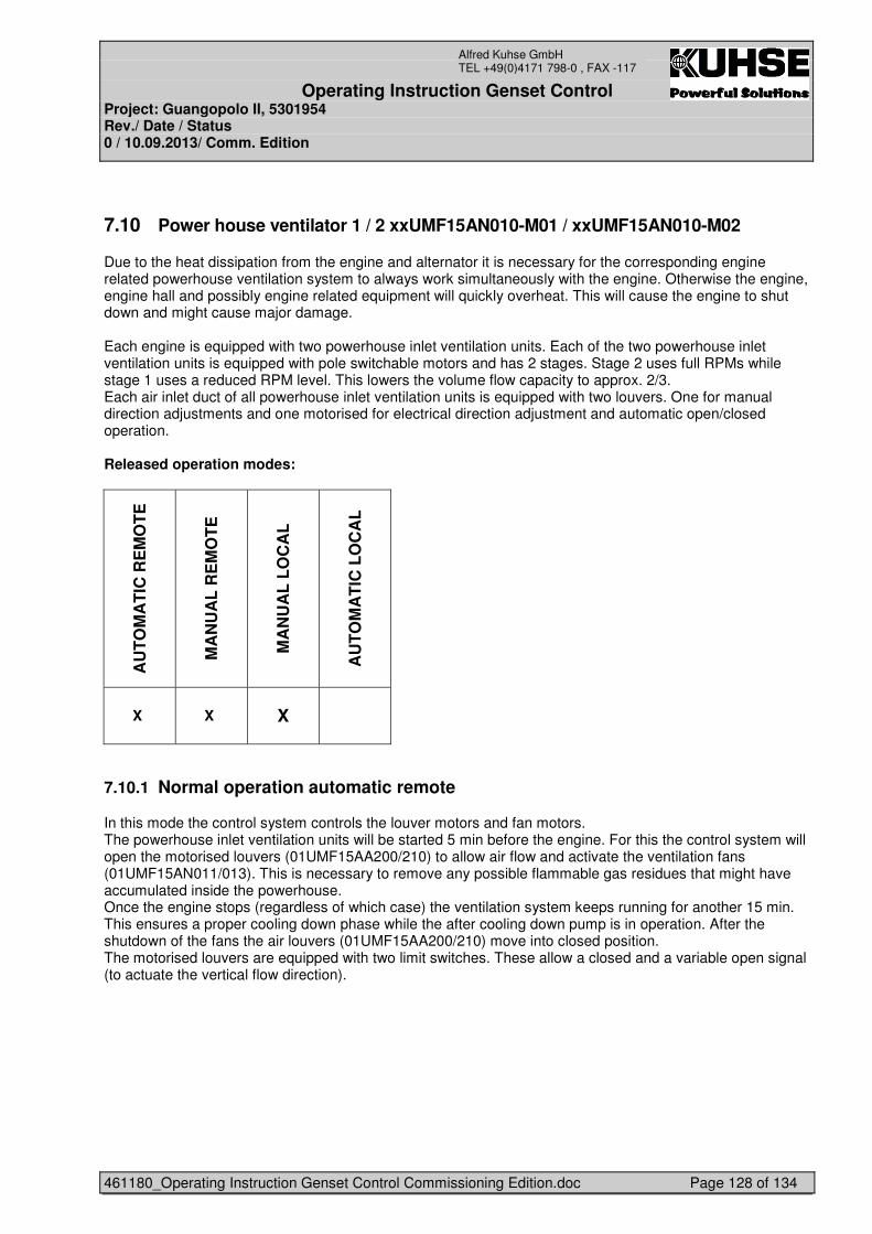
Operating Instruction Genset Control Project: Guangopolo II, 5301954 Rev./ Date / Status 0 / 10.09.2013/ Comm. Edition
461180_Operating Instruction Genset Control Commissioning Edition.doc Page 128 of 134
Alfred Kuhse GmbH TEL +49(0)4171 798-0 , FAX -117
7.10 Power house ventilator 1 / 2 xxUMF15AN010-M01 / xxUMF15AN010-M02
Due to the heat dissipation from the engine and alternator it is necessary for the corresponding engine related powerhouse ventilation system to always work simultaneously with the engine. Otherwise the engine, engine hall and possibly engine related equipment will quickly overheat. This will cause the engine to shut down and might cause major damage. Each engine is equipped with two powerhouse inlet ventilation units. Each of the two powerhouse inlet ventilation units is equipped with pole switchable motors and has 2 stages. Stage 2 uses full RPMs while stage 1 uses a reduced RPM level. This lowers the volume flow capacity to approx. 2/3. Each air inlet duct of all powerhouse inlet ventilation units is equipped with two louvers. One for manual direction adjustments and one motorised for electrical direction adjustment and automatic open/closed operation. Released operation modes:
AU
TO
MA
TIC
RE
MO
TE
MA
NU
AL
RE
MO
TE
MA
NU
AL
LO
CA
L
AU
TO
MA
TIC
LO
CA
L
X X X
7.10.1 Normal operation automatic remote
In this mode the control system controls the louver motors and fan motors. The powerhouse inlet ventilation units will be started 5 min before the engine. For this the control system will open the motorised louvers (01UMF15AA200/210) to allow air flow and activate the ventilation fans (01UMF15AN011/013). This is necessary to remove any possible flammable gas residues that might have accumulated inside the powerhouse. Once the engine stops (regardless of which case) the ventilation system keeps running for another 15 min. This ensures a proper cooling down phase while the after cooling down pump is in operation. After the shutdown of the fans the air louvers (01UMF15AA200/210) move into closed position. The motorised louvers are equipped with two limit switches. These allow a closed and a variable open signal (to actuate the vertical flow direction).
Operating Instruction Genset Control Project: Guangopolo II, 5301954 Rev./ Date / Status 0 / 10.09.2013/ Comm. Edition
461180_Operating Instruction Genset Control Commissioning Edition.doc Page 129 of 134
Alfred Kuhse GmbH TEL +49(0)4171 798-0 , FAX -117
Start procedure of powerhouse ventilation system: Condition definition KKS-Code range value action If Start signal (engine) xxMJA10AG010 Then If Fans signal xxUMF15AN011/013 Yes/No available Yes And Air louvers xxUMF15AA200/210 Yes/No available Yes Then Air louvers xxUMF15AA200/210 Open/Closed To open If Air louver limit switches xxUMF15CG120/180 Open/Closed Open Then fans xxUMF15AN011/013 On/Off On (stage 1)
tdelay start engine 0...30min 5min Then Engine xxMJA10AG010 Release start requirement If Engine xxMJA10AG010 Start/Stop Start Then fans xxUMF15AN011/013 On/Off On (stage 2) If Stop signal (engine) xxMJA10AG010 Then Engine xxMJA10AG010 Start/Stop Stop Then fans xxUMF15AN011/013 On/Off On (stage 1) Then tdelay stop fans 0...30min 15min Start Then Fans 01UMF15AN011/013 On/Off Off Then Air louvers 01UMF15AA200/210 Open/Closed To closed Then Air louver limit switches 01UMF15CG100/160 Open/Closed Closed With regard to a high availability there shall be also the possibility to receive ”release start requirement” and operate the engine for short terms if only one of the twin ventilation towers of the engine has the full functionality for the correct operation. But this operation option should be only used in exceptional cases and a prompt maintenance of the damaged ventilation unit is necessary. MAN Diesel & Turbo SE does not recommend engine ventilating with only one ventilation unit and assumes no responsibility if the operator use this option for continuous operation. In case of two damaged ventilation units the related engine must not be in operation /must be stopped. Please pay attention: - in case of switching down from “full” speed (stage 2) to “low” speed (stage 1), a delay of ten (10) seconds will be needed in order to enable the fan adequately slow down prior to connecting it to lower speed - in case of switching up from “low” speed (stage 1) to “full” speed (stage 2) no delay is needed
7.10.2 Operation manual remote – Powerhouse ventilation system
This mode has to be selected at GCP or SCADA. The operator can switch the Ventilation Fans (01UMF15AN011/13) in manual remote.
When selected the operator can adjust the flow rate of air to the powerhouse as following: - Switch engine hall ventilation fans to stage 1 or 2 - Switch on/off any number of engine hall ventilation fans
In this way it is possible to avoid overcooling in the powerhouse at low ambient air temperatures. The symmetrical air flow to the engines has to be maintained. “Operation manual remote” is not the recommend control mode of MAN Diesel & Turbo. MAN Diesel & Turbo assumes no responsibility if the operator use the ventilation units in “operation manual remote”-mode.
Operating Instruction Genset Control Project: Guangopolo II, 5301954 Rev./ Date / Status 0 / 10.09.2013/ Comm. Edition
461180_Operating Instruction Genset Control Commissioning Edition.doc Page 130 of 134
Alfred Kuhse GmbH TEL +49(0)4171 798-0 , FAX -117
7.10.3 Operation manual local – Powerhouse ventilation system
In this position the pump is manual controlled by hardware push buttons on / off at the switchboard. “Operation manual local” is not the recommend control mode of MAN Diesel & Turbo. MAN Diesel & Turbo assumes no responsibility if the operator use the ventilation units in “operation manual local”-mode.
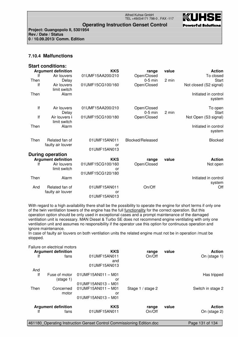
Operating Instruction Genset Control Project: Guangopolo II, 5301954 Rev./ Date / Status 0 / 10.09.2013/ Comm. Edition
461180_Operating Instruction Genset Control Commissioning Edition.doc Page 131 of 134
Alfred Kuhse GmbH TEL +49(0)4171 798-0 , FAX -117
7.10.4 Malfunctions
Start conditions: Argument definition KKS range value Action
If Air louvers 01UMF15AA200/210 Open/Closed To closed Then Delay 0-5 min 2 min Start
If Air louvers limit switch
01UMF15CG100/160 Open/Closed Not closed (S2 signal)
Then Alarm Initiated in control system
If Air louvers 01UMF15AA200/210 Open/Closed To open Delay 0-5 min 2 min Start
If Air louvers l limit switch
01UMF15CG100/180 Open/Closed Not Open (S3 signal)
Then Alarm Initiated in control system
Then Related fan of
faulty air louver 01UMF15AN011
or 01UMF15AN013
Blocked/Released Blocked
During operation Argument definition KKS range value Action
If Air louvers limit switch
01UMF15CG100/160 or
01UMF15CG120/180
Open/Closed Not open
Then Alarm Initiated in control system
And Related fan of faulty air louver
01UMF15AN011 or
01UMF15AN013
On/Off Off
With regard to a high availability there shall be the possibility to operate the engine for short terms if only one of the twin ventilation towers of the engine has the full functionality for the correct operation. But this operation option should be only used in exceptional cases and a prompt maintenance of the damaged ventilation unit is necessary. MAN Diesel & Turbo SE does not recommend engine ventilating with only one ventilation unit and assumes no responsibility if the operator use this option for continuous operation and ignore maintenance. In case of faulty air louvers on both ventilation units the related engine must not be in operation /must be stopped. Failure on electrical motors
Argument definition KKS range value Action If fans 01UMF15AN011
and 01UMF15AN013
On/Off On (stage 1)
And If Fuse of motor
(stage 1) 01UMF15AN011 – M01
or 01UMF15AN013 – M01
Has tripped
Then Concerned motor
01UMF15AN011 – M01 or
01UMF15AN013 – M01
Stage 1 / stage 2 Switch in stage 2
Argument definition KKS range value Action
If fans 01UMF15AN011 On/Off On (stage 2)
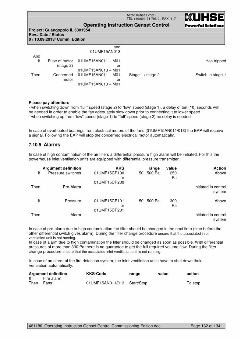
Operating Instruction Genset Control Project: Guangopolo II, 5301954 Rev./ Date / Status 0 / 10.09.2013/ Comm. Edition
461180_Operating Instruction Genset Control Commissioning Edition.doc Page 132 of 134
Alfred Kuhse GmbH TEL +49(0)4171 798-0 , FAX -117
and 01UMF15AN013
And If Fuse of motor
(stage 2) 01UMF15AN011 – M01
or 01UMF15AN013 – M01
Has tripped
Then Concerned motor
01UMF15AN011 – M01 or
01UMF15AN013 – M01
Stage 1 / stage 2 Switch in stage 1
Please pay attention: - when switching down from “full” speed (stage 2) to “low” speed (stage 1), a delay of ten (10) seconds will be needed in order to enable the fan adequately slow down prior to connecting it to lower speed - when switching up from “low” speed (stage 1) to “full” speed (stage 2) no delay is needed In case of overheated bearings from electrical motors of the fans (01UMF15AN011/013) the EAP will receive a signal. Following the EAP will stop the concerned electrical motor automatically.
7.10.5 Alarms
In case of high contamination of the air filters a differential pressure high alarm will be initiated. For this the powerhouse inlet ventilation units are equipped with differential pressure transmitter.
Argument definition KKS range value Action If Pressure switches 01UMF15CP100
or 01UMF15CP200
50...500 Pa 250 Pa
Above
Then Pre-Alarm Initiated in control system
If Pressure 01UMF15CP101
or 01UMF15CP201
50...500 Pa 300 Pa
Above
Then Alarm Initiated in control system
In case of pre-alarm due to high contamination the filter should be changed in the next time (time before the other differential switch gives alarm). During the filter change procedure ensure that the associated inlet ventilation unit is not running. In case of alarm due to high contamination the filter should be changed as soon as possible. With differential pressures of more than 300 Pa there is no guarantee to get the full required volume flow. During the filter change procedure ensure that the associated inlet ventilation unit is not running. In case of an alarm of the fire detection system, the inlet ventilation units have to shut down their ventilation automatically.
Argument definition KKS-Code range value action If Fire alarm Then Fans 01UMF15AN011/013 Start/Stop To stop
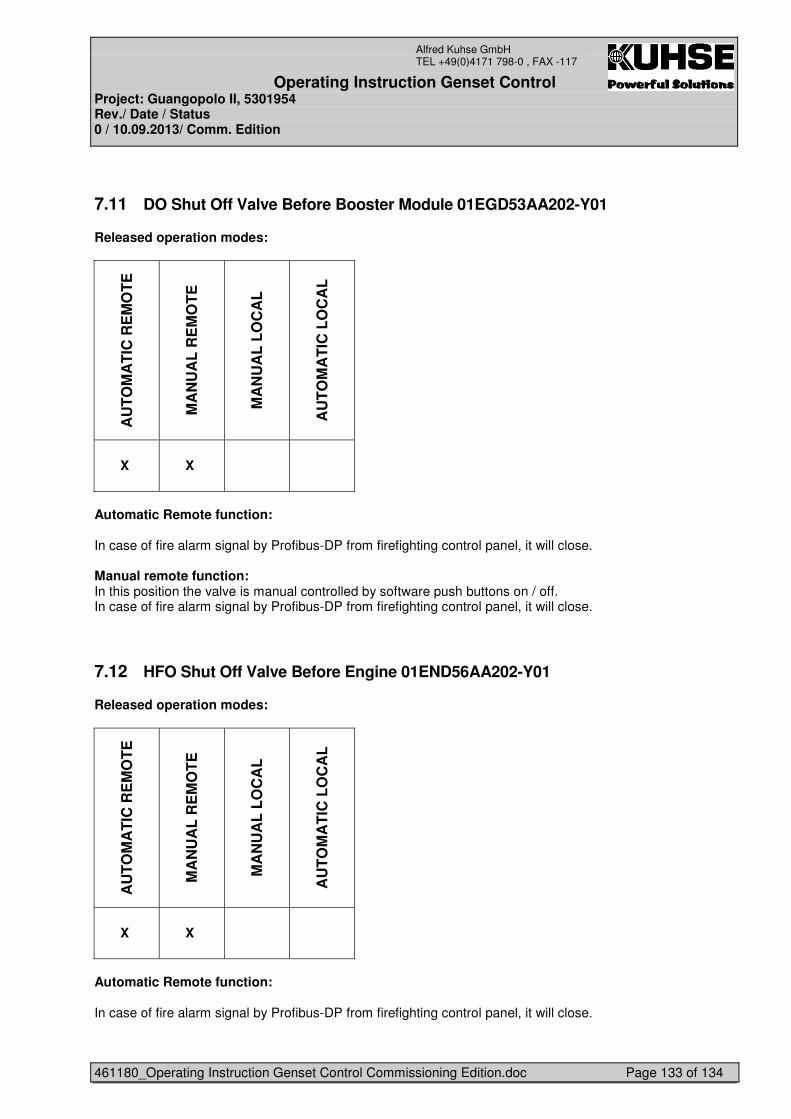
Operating Instruction Genset Control Project: Guangopolo II, 5301954 Rev./ Date / Status 0 / 10.09.2013/ Comm. Edition
461180_Operating Instruction Genset Control Commissioning Edition.doc Page 133 of 134
Alfred Kuhse GmbH TEL +49(0)4171 798-0 , FAX -117
7.11 DO Shut Off Valve Before Booster Module 01EGD53AA202-Y01
Released operation modes:
AU
TO
MA
TIC
RE
MO
TE
MA
NU
AL
RE
MO
TE
MA
NU
AL
LO
CA
L
AU
TO
MA
TIC
LO
CA
L
X X
Automatic Remote function: In case of fire alarm signal by Profibus-DP from firefighting control panel, it will close. Manual remote function: In this position the valve is manual controlled by software push buttons on / off. In case of fire alarm signal by Profibus-DP from firefighting control panel, it will close.
7.12 HFO Shut Off Valve Before Engine 01END56AA202-Y01
Released operation modes:
AU
TO
MA
TIC
RE
MO
TE
MA
NU
AL
RE
MO
TE
MA
NU
AL
LO
CA
L
AU
TO
MA
TIC
LO
CA
L
X X
Automatic Remote function: In case of fire alarm signal by Profibus-DP from firefighting control panel, it will close.
Operating Instruction Genset Control Project: Guangopolo II, 5301954 Rev./ Date / Status 0 / 10.09.2013/ Comm. Edition
461180_Operating Instruction Genset Control Commissioning Edition.doc Page 134 of 134
Alfred Kuhse GmbH TEL +49(0)4171 798-0 , FAX -117
Manual remote function: In this position the valve is manual controlled by software push buttons on / off. In case of fire alarm signal by Profibus-DP from firefighting control panel, it will close.