manx close air support aircraft preliminary design - … · nasw-4435 manx close air support...
TRANSCRIPT
NASW-4435
MANX
Close Air Support AircraftPreliminary Design
California Polytechnic State UniversityAeronautical Engineering Department
Senior Design 90-91
Team Members
Annie AmyDavid Crone
Heidi HendricksonRandy WillisVince Silva
L
(N;.cA-(_ >-] i¢_'Jo2) _A;4Y: L.L_2:_c
&T_',(- _.,_i T _;,, LTV-;T _t.,Y :_ el'"
i-'olyt,.'c'!_ ic :,l _t_ Univ.) :_q
&[i_, 3U;_dPT
(C_I i forni,_
'_ CSCL Oi C
" ._/o5
N o Z - ,_>] 5 _,
https://ntrs.nasa.gov/search.jsp?R=19920012322 2018-07-01T11:39:24+00:00Z

SUMMARY
The Manx is a twin engine, twin tailed, single seat close air support design
proposal for the 1991 Team Student Design Competition. It blends advanced
technologies into a lightweight, high performance design with the following features:
High Survivability:
Rugged, easily maintained, with night/adverse weather
capability-it is well suited for remote site based operations.
Highly Maneuverable:
Negative static margin, forward swept wing, canard, and
advanced avionics result in enhanced aircraft agility.
Highly Versatile-
Design flexibility allows the Manx to contribute to a truly
integrated ground team capable of rapid deployment from forward
sites.

TABLE OF CONTENTS
SUMMARY
LIST OF TABLES
LIST OF FIGURES
LIST OF SYMBOLS
1. INTRODUCTION
. MISSION DESCRIPTION2.1 DESIGN MISSION2.2 HIGH-LOW-LOW-HIGH MISSION2.3 FERRY MISSION2.4 ADDITIONAL PERFORMANCE REQUIREMENTS
0 DESIGN RESULTS3.1 EXCESS POWER PERFORMANCE3.2 FUEL CONSUMPTION3.3 TAKEOFF AND APPROACH PERFORMANCE
4. AIRCRAFT SIZING4.1 SPECIFICATIONS4.2 WEIGHT SIZING REQUIREMENTS4.3 WEIGHT SIZING RESULTS4.4 SELECTION OF DESIGN POINT
5. CONFIGURATION SELECTION5.1 CONFIGURATION DESCRIPTION
5.1.1 WING5.1.2 CANARD5.1.3 TWIN VERTICAL TAILS5.1.4 ENGINES AND INLETS
6. COMPONENT DESIGN6.1 FUSELAGE6.2 WING6.3 COCKPIT LAYOUT6.4 PROPULSIONS INTEGRATION
6.4.1 ENGINE SELECTION6.4.2 INLET INTEGRATION6.4.3 ENGINE PERFORMANCE
6.5 EMPENNAGE SIZING6.5.1 CANARD
iv
iv
vi
11345
68
1011
1111111213
141617171818
19191922252526283030
ii

6.5.2 VERTICAL TAIL6.6 LANDING GEAR
7. AIRCRAFT STRUCTURE7.1 WING STRUCTURE7.2 FUSELAGE STRUCTURE7.3 CANARD STRUCTURE
8. C. G. AND MOMENT OF INERTIA ANALYSIS8.1 COMPONENT WEIGHT AND C.G. LOCATION8.2 MASS MOMENTS OF INERTIA
9. AERODYNAMICS9.1 LIFT ANALYSIS9.2 DRAG ANALYSIS
10. STABILITY AND CONTROL ,
11. AVIONICS
12. FLIGHT CONTROL SYSTEMS LAYOUTS
13. WEAPONS INTEGRATION
14. GROUND SUPPORT REQUIREMENTS
5. LIFE CYCLE COST ANALYSIS
16. CONCLUSIONS AND RECOMMENDATIONS
REFERENCES
APPENDIX
3031
31323233
343437
383839
42
43
45
46
47
49
51
53
56
iii

List of Tables
3.2.1
4.1
5.1
6.2.1
6.2.2
6.4.2.1
6.4.2.2
6.4.3.1
6.6.1
8.1.1
8.1.2
9.2.1
10.1
15.1
Fuel Consumption
Mission Weight Sizing Requirements
Configuration Comparison
Wing Planform Sizing
Airfoil and High Lift Devices
Inlet Pressure Losses
Inlet Area per Engine
Power Extraction Requirements
Landing Gear Tire, Sizing and Rating
Component Weights and C.G. Locations
C.G. Excursion for Range of Loadings
Wetted Areas of Manx Components
Static Stability Derivatives
Life Cycle Cost Breakdown
10
12
15
20
21
27
27
29
31
35
37
39
43
5O
List of Figures
2.1
2.2
2.3
3.1
3.1 .la
3.1 .lb
3.1 .lc
3.2.1
4.3
6.2.1
6.3.1a
6.3.1b
6.3.2
6.3.3
Primary Mission Profile
High-Low-Low-High Mission Profile
Ferry Misssion Profile
Manx Three-view
Excess Power vs Mach Number (sea level)
Excess Power vs Mach Number (10,000 ft.)
Excess Power vs Mach Number (20,000 ft.)
Altitude vs. Maximum Rate of Climb
Design Point Graph
Wing High-Lift-Devices
HOTAS Control Stick
HOTAS Throttle
Manx Cockpit Instrumentation
Cockpit Layout
iv
2
4
5
7
8
9
9
10
13
21
22
23
24
25

7.1.1
7.2.18.1.1
8.1.2
9.1.1
9.1.2
9.2.1
9.2.2
9.2.3
9.2.4
12.1
13.1
15.1
Manx Wing Structure
Fuselage Structure
Manx Component C.G. Locations
C.G. Excursion Envelope
Airplane Lift Curve: TO/Approach, M=.24, sea level
Airplane Lift Curve: Cruise, M=.76, sea level
Drag Polar: Take-off, M=.24, sea level
Drag Polar: Approach, M=.24, sea level
Drag Polar: Cruise, sea level
Drag Polar: Cruise, 20,000 ft.
Flight Control Systems Layout
External Stores Arrangement
Life Cycle Cost Breakdown
32
33
36
36
38
39
40
41
41
42
46
47
51
V

List of Symbols
A
a
b
C
C
C"
cjD
E
e
f
Ixx
lyy
Izz
Ixz
k
L
L/D
M
N
n
q
R
S
S
T
T/W
V
W
W/S
aspect ratio
average accele ration
wingspan
coefficient
chord
chord with flap extended
specific fuel consumption
drag
endurance
efficiency factor
equivalent net parasite areamass moment of inertia
mass moment of inertia
mass moment of inertia
mass moment of inertia
constant
lift
lift to drag ratio
Mach number
number of engines
load factor
dynamic pressure
range
wing area
distance
Thrust
thrust loading
velocity
weight
wing loading
vi
ft
ft/sec 2
ft
ft
Ibs/Ibs/hr
Ibs
hour
ft2
slug • ft2
slug • ft2
slug • ft2
slug • ft2
Ibs
Ibs/ft2
nm
ft2
ft
Ibs
ft/sec
Ibs
Ibs/ft2
P
g
k
A
V
A
c/4
CREW
D
DO
dd
E
F
f
FL
G
L
man
max
mgc
OE
PL
r
req
SL
TO
TOG
t
tfo
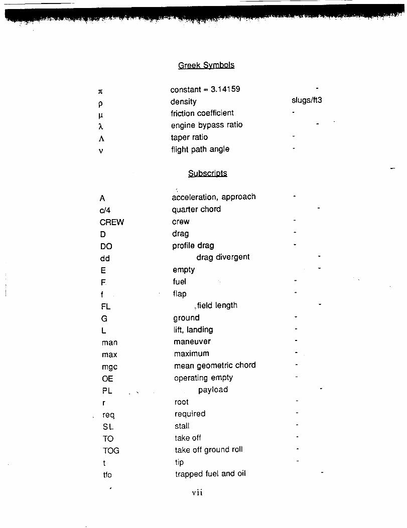
Greek Symbols
constant = 3.14159
density
friction coefficient
engine bypass ratio
taper ratio
flight path angle
acceleration, approach
quarter chord
crew
drag
profile drag
drag divergent
empty
fuel
flap
.field length
ground
lift, landing
maneuver
maximum
mean geometric chord
operating empty
payload
root
required
stall
take off
take off ground roll
tip
trapped fuel and oil
I
slugs/ft3
vii
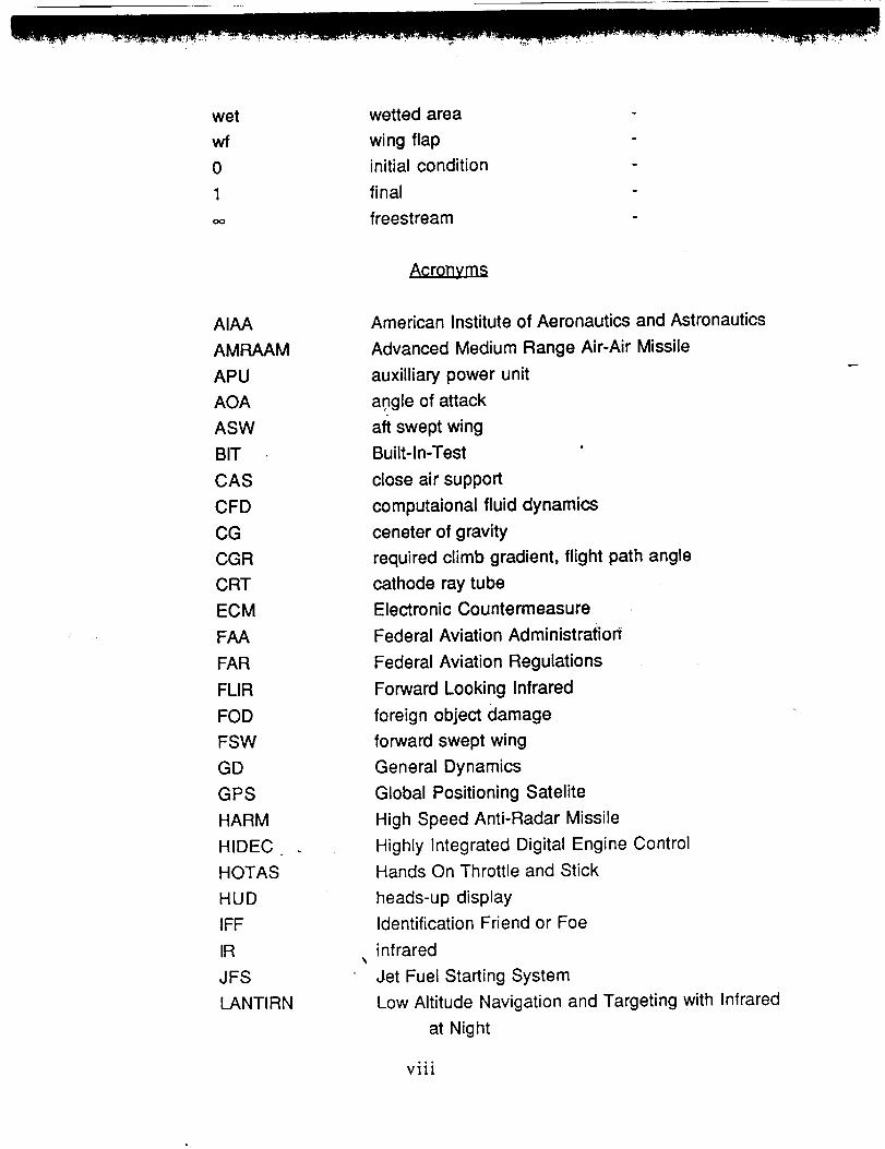
wet
wf
0
1
wetted area
wing flap
initial condition
final
freestream
AIAA
AMRAAM
APU
AOA
ASW
BIT
CAS
CFD
CG
CGR
CRT
ECM
FAA
FAR
FLIR
FOD
FSW
GD
GPS
HARM
HIDEC
HOTAS
HUD
IFF
IR
JFS
LANTIRN
Acronyms
American Institute of Aeronautics and Astronautics
Advanced Medium Range Air-Air Missile
auxilliary power unit
angle of attack
aft swept wing
Built-In-Test
close air support
computaional fluid dynamics
ceneter of gravity
required climb gradient, flight path angle
cathode ray tube
Electronic Countermeasure
Federal Aviation Administration
Federal Aviation Regulations
Forward Looking Infrared
foreign object damage
forward swept wing
General Dynamics
Global Positioning Satelite
High Speed Anti-Radar Missile
Highly Integrated Digital Engine Control
Hands On Throttle and Stick
heads-up display
Identification Friend or Foe
infrared
Jet Fuel Starting System
Low Altitude Navigation and Targeting with Infrared
at Night
ooo
VIII

M
MGC
NACA
OBOGS
OEI
RDTE
RFP
SAS
TFR
UHF
VHF
Mach Number
mean geometric chord
National Advisory Council on Aeronautics
On Board Oxygen GeneratingSystem
one-engine inoperative
research, design, test, and evaluation
request for proposal
stability augmentation system
Terrain Following Radar
ultrahigh frequency
very high frequency
ix

1. INTRODUCTION
As the turn of the century approaches the United States will require an
advanced high-performance Close Air Support (CAS) fighter to replace the
existing Fairchild A-10. This replacement fighter must be able to perform it's
mission well into the twenty first century. The new fighter must be able to
perform the required mission at much higher speeds, carry a greater load, and
deliver ordinances with precise accuracy while operating in a rugged, high
threat environment.
The Manx CAS fighter proposed for the 1991 Team Aircraft Design
Competition is capable of high speeds at low level flight. It has excellent
maneuvering qualities while at the same time carries the required ordinances.
The Manx design incorporates a forward swept wing which is aeroelastically
tailored with composite materials. This wing configuration gives the Manx low
speed maneuverability and low wave drag. Twin engines and twin vertical tails
provide the necessary survivability qualities required for the high threat
environment the the plane will encounter.
2. MISSION DESCRIPTION
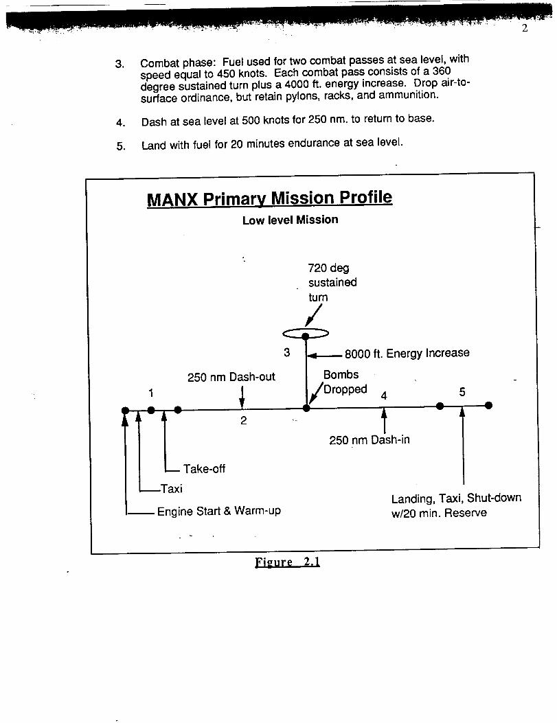
The Manx has been specifically designed for the primal), mission
specified in the design request for proposal (RFP)[32]. The profiles for this
missions is shown in Figure 2.1. Two additional missions were taken into
consideration and the plane was correspondingly configured to perform these
two missions as well. The flight speed used for maximum military power was
500 kts. All of the combat and maneuvering phases were calculated at 350
kts.
2.1 Design Mission ( Primary Mission )
, Warm-up, taxi, takeoff, and accelerate to climb speed. Fuel forthis segment was bas.ed on five minutes at intermediatepower with no range credit.
. Dash at sea level (distance to accelerate to dash speed included inthis segment) at 500 knots to a point 250 nm. from take-off.
.
.
5.
Combat phase: Fuel used for two combat passes at sea level, withspeed equal to 450 knots. Each combat pass consists of a 360degree sustained turn plus a 4000 ft. energy increase. Drop air-to-surface ordinance, but retain pylons, racks, and ammunition.
Dash at sea level at 500 knots for 250 nm. to return to base.
Land with fuel for 20 minutes endurance at sea level.
MANX Primary Mission ProfileLow level Mission
1
Aw
Av
250 nm Dash-out
42
720 degsustained
turn
/
3 _ 8000 ft. Energy Increase
Bombs
Dropped 4
250 nm Dash-in
5
• Av
Engine Start & Warm-upLanding, Taxi, Shut-downw/20 min. Reserve
ELcEt Z

2.2 High-low-low-high mission:
. Warm-up, taxi, takeoff, and accelerate to climb speed with fuelbased on five minutes at intermediate power with no range credit.
. Climb on course at intermediate power to best cruise altitude andspeed.
.
4.
Cruise outbound at best altitude and speed to a range of 150 nm.
Descend to sea level with no time, distance, or fuel used.
. Loiter at sea level at best speed for maximum endurance for a timeas determined by the fuel and payload.
o Dash 100 nm. at sea level (distance to accelerate to dash speedincluded in this segment).
. Combat phase: Fuel used for two combat passes at sea level, withspeed equal to maximum speed in military power minus 50 knots.Each combat pass consists of a 360 degree sustained turn plus a4000 ft. energy increase. Drop air-to-surface ordinance, but retainpylons, racks, and ammunition.
8. Dash 100 nm. at sea level.
9. Climb (on return course) to best cruise altitude and speed.
10. Cruise back at best altitude and speed to a total distance of 150 nm.for segments 9 and 10.
11. Descend to sea level; no time, distance, or fuel used.
12. Landwith fuel for 20 minutes endurance at sea level.

4
High-Low-Low-High Mission Profile8000 ft.
250 nm150 nm Dash-out at Energyaltitude Increase 720 deg Dash-in
sustainedturn
103
Climb
1
Descent
Loiter 5
6
Take-off
axi
Engine Start &
Warm-up
7
100 nm. Dash
at sea level
Climb
Bombs 1_2Dropped
Landing, Taxi, Shut-downw/20 min. Reserve
FIGURE 2.2
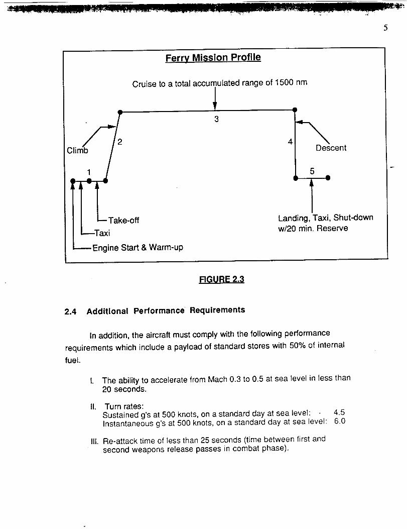
2.3 Ferry Mission: (Payload is replaced with fuel. No air-to-air refueling)
• Warm-up, taxi, takeoff, and accelerate to climb speed. Fuel forthis segment was based on five minutes at intermediate power withno range credit.
. Climb.on course at intermediate power to best cruise altitude andspeed.
. Cruise outbound at best altitude and speed to a total accumulatedrange of at least 1,500 nm.
4. Descend to sea _evel; no time, distance, or fuel used.
5. Land with fuel for 20 minutes endurance at sea level.
Ferry Mission Profile
Cruise to a total accumulated range of 1500 nm
o
i[.--- Take-off
_Taxi
3
Descent5
Landing, Taxi, Shut--6own
w/20 rain. Reserve
Engine Start & Warm-up
RGURE 2.3
2.4 Additional Performance Requirements
In addition, the aircraft must comply with the following performance
requirements which include a payload of standard stores with 50% of internal
fuel.
I. The ability to accelerate from Mach 0.3 to 0.5 at sea level in less than20 seconds.
II. Turn rates:
Sustained g's at 500 knots, on a standard day at sea level: 4.5Instantaneous g's at 500 knots, on a standard day at sea level: 6.0
III. Re-attack time of less than 25 seconds (time between first andsecond weapons release passes in combat phase).

6
3 DESIGN RESULTS
The design results for the Manx fighter follow. The Manx three-view and
tabulated geometry can be found in Figure 3.1. The performance curves for
excess power, rate-of-climb and engine fuel consump!ions are,also presented
in this section.

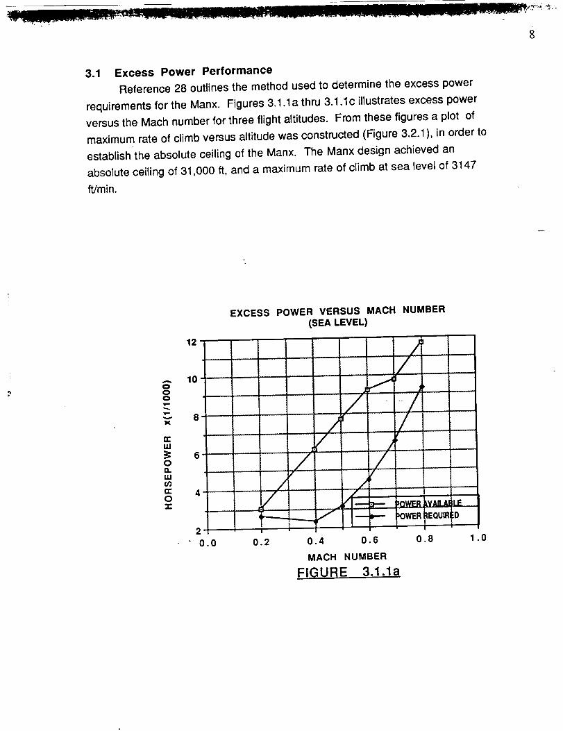
3.1 Excess Power Performance
Reference 28 outlines the method used to determine the excess power
requirements for the Manx. Figures 3.1. la thru 3.1.1c illustrates excess power
Versus the Mach number for three flight altitudes. From these figures a plot of
maximum rate of climb versus altitude was constructed (Figure 3.2.1 ), in order to
establish the absolute ceiling of the Manx. The Manx design achieved an
absolute ceiling of 31,000 ft, and a maximum rate of climb at sea level of 3147
ft/min.
ooo
v
>¢
n-ILl
oO.LLIO3n-O-r
12
10
8
,
,
20.0
EXCESS POWER VERSUS MACH NUMBER(SEA LEVEL)
/
ii .....
i ZT // /
pOWER (_EOU[R:g
I
0.2 0.4 0.6 0.8 1.0
MACH NUMBER
FIGURE 3.1.1a

9
,....,.
oo
X
IZ:LU
0
LU03IZ:02:
10
6
EXCESS POWER VERSUS MACH NUMBER
(10,000 ft)
I
4
2
0.3 0.4
i
0.5 0.6
H.J/" ....
/L
/
- -/'" '
/
j/f-
...... _'V_ _'"nl"
!
0.7 0.8 0.9
MACH NUMBER
FIGURE 3.1.1b
A
ooo
v
X
n"LU
OO.LU03n-On-
EXCESS POWER VERSUS MACH NUMBER
(20,000 It)
P'-- POWER A_AIL_ 3LE
"--" _--" I POW ER Ri _QUIF EDL _ ...................6 /
....
5 r /J
4 /
._._f
T2
0.3 _ 0.4 0.5 0.6 0.7 0.8 0.9
MACH NUMBER
FIGURE 3.1.1c

10
35
30
00
25
X
20
uJ 15
I-- 10,..J,,<
ALTITUDE VERSUS MAXIMUM RATE OF CLIMB
0 °
0.0
a | J .... t
............................... I bsoi Ute-Ceii ing 3i o00 Tt...........
_'L I .¢iervii:e.... Cellirg 29 100 It
.......[_-],_ ....... iiiiiiiiii_ill_ilil__iiiilliiliiii_ilili_;iiiiiiil;iiiiii
...... .........,121:__illl211221]illii2]221ill2Liilliiiiili22111111
....... _"_ilill:il
0.5 1.0 1.5 2.0 2.5 3.0 3.5
MAXIMUM RATE OF CLIMB ~ft/mln x(111000)
FIGURE 3.2.1
3.2 Engine Fuel Consumption
A further consideration of engine performance is the design engine's
thrust specific fuel consumption, cj. The Manx is evaluated for the low-levelmission and the ferry mission using the design engine cycle data, for climb,cruise and best cruise altitude (Table 3.2.1).
]'able 3.2.1 Fuel
Mission Condition CJ
Low Level Climb 0.64 - 0.72
Cruise 0.65
Ferry' Best cruise Altitude 0.68

]!
3.3 Take-off and Approach Performance
The Manx was designed from its early conception to be suited for remote
site based operations. This requires it to takeoff and land within 2000 ft. after
clearing a 50 ft. obstacle on runways that are difficult to maintain. As a result,
design considerations were performed to meet these objectives.
The landing gear was designed for use on dirt or grass strips with tire
sizing done to accommodate these surfaces. The capability to land and takeoff
within 2000 ft. after clearing a 50 ft. obstacle is a function of the aircraft's design
point characteristics. The stall speed of the aircraft was computed to be 114
knots at takeoff and 104 knots at landing, in a fully loaded configuration. Using
Reference 23 (ch5.1), the Manx's take-off ground roll distance to clear a 50 ft.
obstacle was computed to be 1512 ft. which adequately fulfills the 2000 ft.
requirement with a 500 ft. safety margin.
4. AIRCRAFT SIZING
4.1 Specifications
The Federal Aviation Administration requires that sizing data for all
military aircraft must comply with FAR 25 specifications. Reference 1 provides
methods for the preliminary sizing estimations which are in compliance with
FAR 25.
4.2 Weight Sizing Requirements
Estimating the gross take-off weight, WTO, empty weight, WE, and the
mission fuel weight, WF, is dependent upon the mission range, endurance,
speed and payload-carrying requirements of the design mission. These
requirements are outlined in the Mission Specifications.
Reference 1 develops the iterative method which was employed in this
study to determine WTO, WE, and WF. This method utilized empirical data
obtained from similar aircraft and the Breguet's range and endurance
equations, which in turn were used to calculate the fuel fractions of each phase
I - _'-_-.-_-'_-_- - I I • .............. ir TM i ,, .... ;_: - .....
12
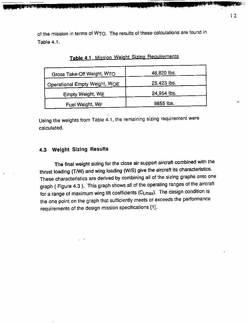
of the mission in terms of WTO. The results of these calculations are found in
Table 4.1.
Table 4,1 Mission Weight Sizing Reauirements
Gross Take-Off Weight, WTO 48,820 Ibso
Operational Empty Weight, WOE 25,423 Ibs.
Empty Weight, WE 24,954 Ibs.
Fuel Weight, WF 9855 Ibs.
Using the weights from Table 4.1, the remaining sizing requirement were
calculated.
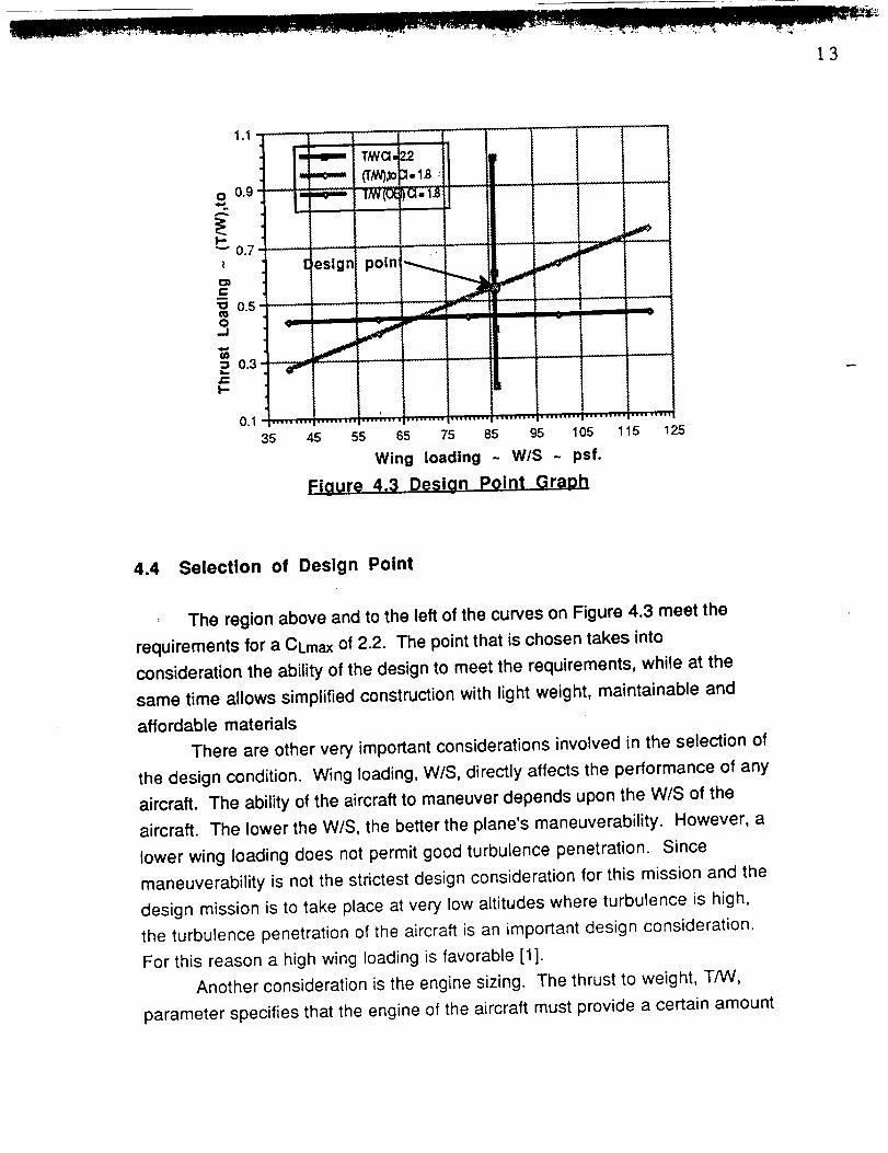
4.3 Weight Sizing Results
The final weight sizing for the close air support aircraft combined with the
thrust loading (T/W) and wing loading (W/S) give the aircraft its characteristics.
These characteristics are derived by combining all of the sizing graphs onto one
graph ( Figure 4.3 ). This graph shows all of the operating ranges of the aircraft
for a range of maximum wing lift coefficients (CLrnax). The design condition is
the one point on the graph that sufficiently meets or exceeds the performance
requirements of the design mission specifications [1].
1.1
O 0.9
F-"_" 0.7
z
e,,
0.5O..J
==L_
J_I--
0.3
[leslgn poin_
0,1
35 45 55 65 75 85 95 105 115 125
Wing loading ~ W/S ~ psf.
Figure 4,3 Design Point Graph
4.4 Selection of Design Point
, The region above and to the left of the curves on Figure 4.3 meet the
requirements for a CLmax of 2.2. The point that is chosen takes into
consideration the ability of the design to meet the requirements, while at the
same time allows simplified construction with light weight, maintainable and
affordable materials
There are other very important considerations involved in the selection of
the design condition. Wing loading, W/S, directly affects the performance of any
aircraft. The ability of the aircraft to maneuver depends upon the W/S of the
aircraft. The lower the W/S, the better the plane's maneuverability. However, a
lower wing loading does not permit good turbulence penetration. Since
maneuverability is not the strictest design consideration for this mission and the
design mission is to take place at very low altitudes where turbulence is high,
the turbulence penetration of the aircraft is an important design consideration.
For this reason a high wing loading is favorable [1].
Another consideration is the engine sizing. The thrust to weight, T/W,
parameter specifies that the engine of the aircraft must provide a certain amount

of thrust in relation to the weight of the plane. For a given aircraft weight, a large
T/W implies a larger, heavier and more expensive power plant. A larger enginewould use more fuel thus reducing the maximum range or requiring more fuel
capacity. For these reasons, it would be beneficial to have a lower thrust to
weight ratio [1].
The design point was chosen from Figure 4.3 by taking intoconsideration the previously mentioned criteria. A CLmax of 2.4 was specified by
the design group for each regime of the flight envelope. Each CL for a flight
condition was selected based upon the design groups expectation of the design
to achieve that C L. This criteria was used to systematically remove all of the
curves which were below or to the left of the design CI for a particular flight
regime. Figure 4.1 shows the operational flight envelope of the aircraft, with all
of the points above and to the left of the curves meeting the performance
requirements [1].
Applying the criteria for a high W/S and low T/W to this graph, it can be
seen that the best point for the design lies where the landing performance and
take-off performance curves intersect. This point corresponds to a W/S = 87.5
psf. and T/W = 0.54. Although these points optimize the aircraft for the design
mission, it does not take into consideration the performance and maneuvering
capabilities of the Manx. These added performance requirements dictated a
higher T/W. For this reason, for the final configuration, a T/W of 0.635 was used
to meet all performance parameters.
5. CONFIGURATION SELECTION
The Manx CAS fighter was designed to meet all of the performance
requirements of the RFP. Using these requirements, a number of critical design
parameters were .identified which are listed below:
1. High subsonic Mach Numbers. M= 0.76
2. High maneuverability at low speeds
3. Survivability in high threat environment

Many different designs were considered for the proposed close airsupport role. These different design configurations are compiled in Table 5.1.
The advantages and disadvantages are stated for each design.
Conficjuration
Helicopter
Tilt-rotor
Conventional
tail
Rearward
sweep
Canard
l'able 5.1 Confiauration Comparison
Advantages
no runway required
good maneuverability
good stealth
capabilities
no runway required
good for rough terrain
good speed range
contributes to aircraft
stability
good downward
visibility
low wave drag
good downward
visibility
smaller control
surfaces
vortex coupling with
main wing
Disadvantages
inadequate speed
high maintenance
complex expensive
low survivability
high maintenance
complex expensive
larger control surfaces,
heavier
higher take-off speed
higher landing speed
poor stall characteristics
contributes to aircraft
instability
16
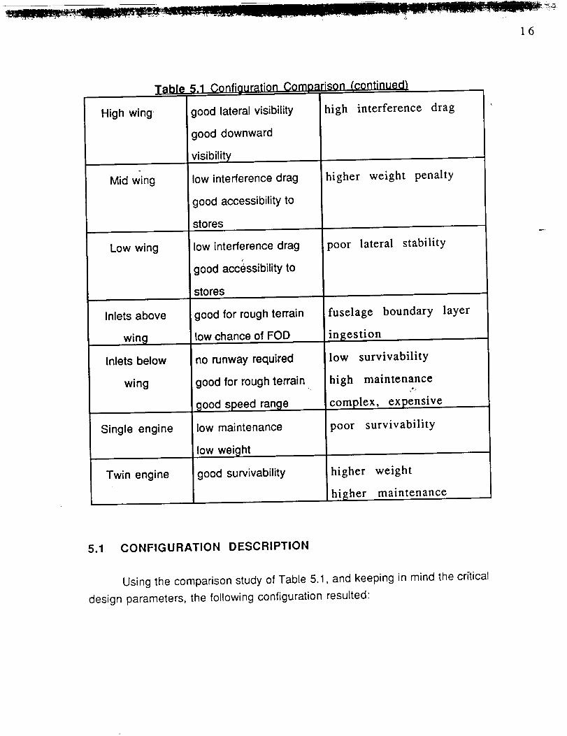
Table 5.1 Configuration Comparison !continued!
High wing' good lateral visibility
Mid wing
Low wing
Inlets above
wing
Inlets below
wing
Single engine
Twin engine
good downward
visibility
low interference drag
good accessibility to
stores
low interference drag
good accessibility to
stores
good for rough terrain
low chance of FOD
no runway required
good for rough terrain
good speed range
low maintenance
low weight
good survivability
high interference drag
higher weight penalty
poor lateral stability
fuselage boundary
ingestion
low survivability
high maintenance
complex, expensive
poor survivability
higher weight
higher maintenance
layer
5.1 CONFIGURATION DESCRIPTION
Using the comparison study of Table 5.1, and keeping in mind the critical
design parameters, the following configuration resulted

j .................. - __ _
17
Forward Swept Wing
Canard configuration
Twin vertical tails and engines
Over-wing inlets location
Mid-wing location ,
A complete three-view drawing of the Manx configuration can be found in
Figure 4.1. as well as the tabulated geometry for all of the airframe components.
A more in depth description of the Manx configuration follows.
5.1.1 Wing ,
The forward swept wing was chosen because of its capability of high
subsonic flight speed with low drag rise due to compressibility. It also exhibits
excellent maneuverability at high angle-of-attack (AOA), and good low speed
lateral control capabilities [14]. The disadvantages of weight and structural
divergence are to be eliminated by the use of aeroelastically tailored
composites. The wing is swept forward 25 degrees at the quarter-chord. A mid-
wing position was chosen to minimize the wing/fuselage interference drag. It
also allows for the wing box to ,be carried through the fuselage thus taking "
advantage of weight saving synergism as well as simplifying the construction.
Fowler flaps and a leading edge slat are to be deployed during take-off and
landing to achieve the required Clmax. Ailerons are located at the wing tips for
the lateral control of the aircraft. The wing has been constructed to allow for the
incorporation of spoilers if they are needed for additional roll control.
5.1.2 Canard
A canard was selected primarily due to smaller required control surface
areas resulting in lower skin friction drag on the Manx. The canard provides a
downward force at trimmed conditions_ and provides the instability required for
increased maneuverability. The chord line of the canard is placed two feet
above the main wing chord line. This has been done in order to take advantage
of the canard tip vortices interacting with the main wing boundary
layer,providing increased lift at high AOA [13]. A smaller control surface is
possible with a canard because it is not being down-washed by the main wing
18
as are conventional tails. The canards are full moving surface devices that act
as high lift devices on take-off and landing. They are differential as well to add
to the lateral control of the aircraft in flight, and can be employed as speed
brakes to decrease landing distance[ ].
5.1.3 Twin Vertical Tails
Twin tails were selected for redundancy, increasing the survivability
aspect of the plane. They are also effective in providing good lateral control
qualities at high AOA. In addition, the twin tails serve to reduce the airplane's
side profile lessening the chance of visual detection. They are canted 55
degrees to reduce the radar image and to position them out of the wake of the
fuselage for increased directional control at high AOA [20]. Also, since the
thrust lines of the two engines are off-set from the aircraft center line, the two
tails provide good directional control in a one-engine-out-operation
configuration.
5.1.4 Engines and Inlets
It was determined that two engines would adequately meet the thrust
requirements for the Manx. The twin engine configuration also allows for the
flexibility of being accepted for use as a Navy based fighter;_ A one engine
configuration would make it necessary to develop a high thrust, light weight
engine and would reduce the survivability of the fighter. The engine used was
designed from parameters taken from a thrust augmented rubber engine
[29](see Appendix). The inlets have been placed above the wing with the
opening one foot in front of the leading edge. Over-wing inlets reduce the
possibility of foreign object damage (FOD) that may result from the plane
operating from undeveloped airfields. The placement also makes it difficult for
hostile ground fire to be ingested by the engines. The inlets are also canted
down 6 deg. in order to maximize uniform inlet flow and to decrease the
possibilities of flow separation from the inlet lip at high AOA flight.
6. COMPONENT DESIGN
6.1 Fuselage
The fuselage has been design to enhance the high subsonic flight
capabilities of the Manx. For this reason, a fineness ratio of 8 was chosen. This
provides the lowest fuselage drag [19]. A detailed drawing of component
placement can be seen in Figure 6.1.1 (System inboard profile). The large
fuselage cross section was necessary to contain the large 30 mm. GAU-8a
cannon. This gun has been placed so that the C.G. of the ammunition lies very
close to the C.G. of the Manx. This minimizes C.G. travel as the ammunition is
used. The firing barrel of the gatling gun has been placed along the center-line
of the fuselage which eliminates the control problems associated with the gun
recoil when firing. The major electronic components are placed behind the
pilot. These along with the pilot are enclosed in a Kevlar cockpit shield. This
cockpit shield is designed so that the pilot is protected from small arms ground
fire and shrapnel from anti-aircraft fire. The nose cone contains the Radar and
Forward Looking Infrared units. The Auxiliary Power Unit is contained in
between the two engine inlets in front of the engines and on top of the wing.
The climate control system is located below the cockpit.
6.2 Wing
The Manx utilizes a tailless, forward swept wing (FSW), and canard
configuration. The wing is cantilevered to avoid the drag of external bracing. A
mid wing was chosen to allow for better engine placement above the wing, less
interference drag, good lateral stability, good visibility from the cockpit, and a
lower landing gear weight. A forward swept wing was chosen, because of the
superior maneuverability capabilities at transonic Mach numbers. The
construction of the FSW will utilize composites to take advantage of the
aeroelastic tailoring capabilities. This will allow the wing to bend under load,
which will delay the flutter and divergence associated with the FSW. The FSW
creates a higher swept sh6ck at the trailing edge, resulting in lower pressure
drag. This allows for a lower sweep angle than an Aft Swept Wing (ASW)
resulting in a higher lift curve slope, and lower subsonic induced drag. The

20
spanwise flow component of the FSW is directed toward the root, promoting root
stall as opposed to tip stall, which occurs with an ASW, allowing for greater use
of the ailerons at higher AOA and thus greater maneuverability. [6]For the planform design, initial values for wing thickness ratio, taper ratio,
and sweep angle were chosen referencing existing aircraft. The airfoil was thenselected for the predicted required lift coefficients at various configurations. The
wing employs a series of airfoils; a NACA 65-210 at the root, down linearly to a
NACA 65-208 at the tip. The high lift device sizing took several iterations to
achieve the required space for the desired control surfaces. Smaller flaps were
achieved with the added penalty of higher complexity and cost. Table 6.2.1
shows the resulting wing planform parameters while Figure 6.2.1 shows the
high-lift -devices layout and oPeration. [18]
Table 6.2.1 Wing Planform Sizina
b 53 ft.
S 558 sq. ft.
A 5.0
Ac/4
Ct
-25 deg.
7.5 ft.
10.75 ft.
0.55
Fuel volume 230. cu. ft.

21
Table 6.2.2
Airfoil
Fowler flap
Airfoil and Hiah Lift Devices
root: NACA 65-210
tip: NACA 65-208
cflc = 0.3
Swf/S = 0.68
Leading edge slat c"/c = 1.126
Flap deflection takeoff: 20 °
land: 40 °
Maximum lift coefficient takeoff: 2.0,.
land: 2.4
Clean Confiauration: Cruise
Take-off Configuration: 20 deg. Fowler flaos
Landing Configuration" full slats. 40 deg Fowler flaps
Figure 6.2.1 Wing High-Lift-Devices

22
6.3 Cockpit Layout
The aircraft controls are the standard center stick and side throttle
configuration based on that of the McDonnell Douglas F-15 Eagle. The control
layout employs the Hands On Throttle and Stick (HOTAS) philosophy which
allows the pilot to operate vital combat functions without removing his hand from
the the aircraft controls. The HOTAS system allows a decreased work load for
the pilot and also a faster response time in combat situations. This system has
proven itself valuable in actual combat. The control stick and throttle
arrangement for the Manx can be seen in Figure 6.3.1a,b. [33]
HUD camera & gun trigger
SRM/EO weapon seekerhead control
Autopilot/nose gear steeringrelease switch
Trim button
Weapon release button...L
Radar auto acquisition switch
Figure 6.3.1a HOTA$ Control Stick

23
IFF interogate button--- 7
_a_et designation control
switcMicrophone Radar antenna elevationcontrol
Weapon selection switch ECM dispencer switch
Figure 6.3.1b HOTAS Throttle
Instrumentation is arranged in a display format similar to that of the
McDonnell Douglas/Northrop F/A-18 Hornet (see Figure 6.3.2). This display
takes advantage of the multifunction CRT displays as well as a fully integrated
HUD. The system is designed to lower the pilots combat work load by placing
only the most important information in front of the pilot as it is neecled. The CRT
displays are programmable so that they can act as different displays are
needed for particular missions. Not only does this allow more flexibility for the
aircraft configuration but it allows a more efficient use of the instrumentation
displays. The cockpit orientation and pilot position can be seen in Figure
6.3.3. The arrangei'nent allows for the pilot to have good 360 ° visibility.

24
m
I _ I
8 191
4
2
j L
5
mq-t _12
l
E]
27
Manx Cockpit
1 Master monitordisplay(CRT)2 Up-front control panel3 Multi-functiondisplay (CRT)4 Integrated head-up display (HUD)5 Horizontal situationdisplay (CRT)6 Master armament panel7 Stores jettison indicators8 Digital engine monitor display9 Fuel quantity indicator
10 Standby magnetic compass11 Attitude referrence indicator12 Radar warning display13 Stanby airspeed indicator14 Standby altimeter15 Vertical speed indicator16 ECM monitor panel17 ECM control panel18 Clock19 Cabin pressure altimeter20 Warning panel21 Caution light panel22 Altitude indicator23 Landing light plate24 Brake pressure indicator25 Landing gear controls26 Static pressure source selector27 Hydraulic pressure indicator
Instrumentation

[] lit J_ III 1111
25
.3 °
Figure 6.3.3 Cockpit Layout
6.4 Propulsions Integration
6.4.1 Engine Selection
The engine parameters for the Manx is based on a design engine. This
design e.ngine meets the mission requirements specified in the RFP, for Mach
number, altitude, thrust, mass airflow, fuel flow, and specific fuel consumption.

26
6.4.2 Inlet Integration
The preliminary design process for inlet sizing is dependent on several
important factors. These factors are as follows:
Subsonic Performance
Pressure Recovery
Landing Gear/Fuel Storage
Foreign Object Damage
Gun Exhaust Gas Ingestion
Undisrupted Flow Into Inlets
Reduce Spillage Drag
The Manx inlets are constructed such that the engine airflow
requirements can be met. This includes determining the inlet area and the
geometric configuration of the duct leading to the engine compressor face,
which is essential for minimizing the total stream tube wetted-area and the
viscous pressure losses. The inlet geometry is designed for a range of flight
modes; specifically, for the required range of flight Mach numbers and engine
performance requirements specified by the Manx's design engine.
The Manx incorporates internal-compression subsonic inlets which are
semi-circular in cross section at the cowl and diverge in circular cross-sections
to the compressor face. The inlet stream tubes are 9.0 ft. long, which allows for
a gradual area transition from the inlet face to the fan face. This avoids severe
angle deflections in the stream tube, which eliminates flow separation in the
inlet duct which can induce diffuser stall, and reduces the energy losses in the
internal-compression inlet. Consequently, the positive pressure-gradient along
the diffuser length is kept small. Table 6.4.2.1 lists the inlet pressure losses for
variations in Mach number and altitude. Turbofan engine performance analysis
has determined these values to be highly favorable for high pressure recovery
at the compressor face, which minimizes the turbine work required to compress
the air flow.
The above-wing disposition of the inlets and engines, along with the
straight through configuration aide in maximizing fuel and landing gear storage
27
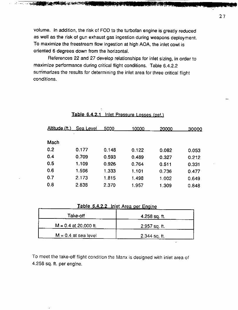
volume. In addition, the risk of FOD to the turbofan engine is greatly reduced
as well as the risk of gun exhaust gas ingestion during weapons deployment.
To maximize the freestream flow ingestion at high AOA, the inlet cowl is
oriented 6 degrees down from the horizontal.
References 22 and 27 develop relationships for inlet sizing, in order to
maximize performance during critical flight conditions. Table 6.4.2.2
sunimarizes the results for determining the inlet area for three critical flight
conditions.
Table 6.4.2.1 Inlet Pressure Losses (Dsf,)
Altitude (ft.) Sea Level 5000 10000 20000 30000
Mach
0.2 0.177 0.148 0.122 0.082 0.053
0.4 0.709 0.593 0.489 0.327 0.212
0.5 1.109 0.926. 0.764 0.511 0.331
0.6 1.596 1.333 1.101 0.736 0.477
0.7 2.173 1.815 1.498 1.002 0.649
0.8 2.838 2.370 1.957 1.309 0.848
Table 6.4.2.2 Inlet Area per Enaine| m
Take-off
M = 0.4 at 20,000 ft.
M = 0.4 at sea level
4.258 sq. ft.
2.957 sq. ft.
2.344 sq. ft.
To meet the take-off flight condition the Manx is designed with inlet area of
4.258 sq. ft. per engine.

The Manx inlets incorporate boundary layer splitters to avoid
consumption of the boundary layer which develops along the fuselage
upstream of the inlets. This improves flow conditions to the turbofan engine,
greatly reducing the occurrence of disrupted flow entering the inlets, and
maximizing engine performance.
6.4.3 Engine Performance
The performance of the Manx is based on the following requirements:
Thrust/Power Available
Thrust/Power Required
Altitude Effects on Thrust�Power Required and Available
Rate of Climb/Maximum Rate of Climb
Absolute and Service Ceilings
The Manx design engine cycle data provided the available uninstalled
thrust data. Reference 22 outlines the method used to obtain the available
installed thrust values. Considerations for the available thrust included Mach
number effects, and power extraction from the engine for operation of electrical,
mechanical, and pneumatic equipment on board the Manx. Table 6.4.3.1 lists
power extraction requirements, however, the Mach number is the main variable
for available installed thrust.

29
Table 6.4.3.1 Power Extraction Requirements
Electrical
Radar
NavigationWeapons DeploymentControl Surface Deflection
Mechanioal
Fuel PumpsHydraulic PumpsCooling FansPressurization Systems
,. Air conditioning/Heating Systems
Pneumatic
Anti-icing SystemsEngine Starting SystemsFuel Tank Pressurization
Flap/Control Surface Deployment
Thrust and power required are basedon the drag polar calculations of
Section 9 for the Manx. Reference 28 outlines the method used to calculate
thrust/power required, which are primarily a function of the aircraft drag
coefficient and the flight Mach number. The aircraft is assumed to be in level
and unaccelerated flight for this analysis.
Altitude effects on thrust/power required and available are only a function
of density. Specifically, they are a function of the ratio of standard sea level
density to the density at altitude. This analysis assumes a standard day.
For rate of climb it is assumed that the Manx is in steady, unaccelerated
climbing flight. For this assumption, the rate of climb is determined for the
power available/required curves versus velocity curves, where rate of climb is
the ratio of the excess power to the aircraft weight. Based on this analysis, the
maximum rate of climb is obtained from the maximum excess power.
Absolute and service _:eilings are listed in Figure 3.2.1 for maximum rate
of climb versus altitude. Refer to the results section of this report for a complete
presentation of the performance curves.

30
6.5 Empennage Sizing
The empennage parameters for the
geometry table of Figure 3.1.
6.5.1 Canard
Manx are summarized in the
The canard sizing was determined by the level of instability of the Manx
and its effect on take-off trim. With the aircraft highly unstable, a symmetric
airfoil was chosen for the canard so that lift could be provided equally in either
direction. Positioning the canard as far forward of the wing as possible while
keeping it behind the pilot to'provide good visibility, provided the smallest
required canard area. The resulting longitudinal feedback gain, Koq was not a
limiting factor for the canard sizing.
The canard was designed as a fully movable surface. This feature allows
the canard to serve as an effective brake when landing. The canard is also fully
differential which allows for synergism with the ailerons to enhance roll
capability. A high vertical positioning of the canard was chosen to minimize
inlet air flow disruption during level and positive angle of attack flight. This
position also provides the pilot with minimal vision obstruction. Existing canard
aircraft of similar configurations were examined for aid in designing the
planform of the canard.
6.5.2 Vertical Tall
Vertical tail sizing for the Manx was determined primarily by the yaw
recovery requirement for the one engine inoperative (OEI) condition during
take-off. In placing the tails 3 ft. from the fuselage centerline, the flow
disruptions from the fuselage wake which become significant at high AOA are
reduced. This characteristic was further enhanced by canting the tails outward
55 degrees. Twin vertical tails also provide redundancy in the event one tail is
damaged, and serves to reduce the overall airplane height. With the directional
response increased by the added moment arms provided by twin tails, the
sideslip-to-rudder feedback gain was not a restrictive sizing parameter.
m" I IIII I ....
•":qr-:'_ :r" "_° _ _':';_-.'l _::-_-...__-_:,_.;#.;4,_=._=_,_-_..I _._
3]
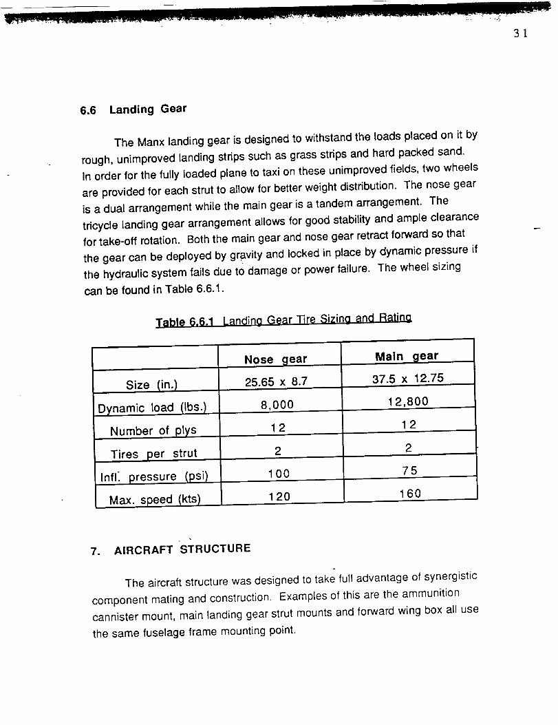
6.6 Landing Gear
The Manx landing gear is designed to withstand the loads placed on it by
rough, unimproved landing strips such as grass strips and hard packed sand.
In order for the fully loaded plane to taxi on these unimproved fields, two wheels
are provided for each strut to allow for better weight distribution. The nose gear
is a dual arrangement while the main gear is a tandem arrangement. The
tricycle landing gear arrangement allows for good stability and ample clearance
for take-off rotation. Both the main gear and nose gear retract forward so that
the gear can be deployed by gravity and locked in place by dynamic pressure if
the hydraulic system fails due to damage or power failure. The wheel sizing
can be found in Table 6.6.1.
Table 6.6.1 Landing Gear Tire Sizing and Rating
Size (in.)
Dynamic load (Ibs.)
Number of plys
Tires per strut
Infl_ pressure (psi)
Max. speed (kts)
Nose gear
25.65 x 8.7
8,000
12
Main gear
37.5 x 12.75
12,800
12
2 2
100 75
120 160
7. AIRCRAFT STRUCTURE
The aircraft structure was designed to take full advantage of synergistic
component mating and construction. Examples of this are the ammunition
cannister mount, main landing gear strut mounts and forward wing box all use
the same fuselage frame mounting point.

3:2
7.1 Wing Structure
The forward swept wing of the Manx fighter is to be constructed from
composite materials. The use of composite materials allows for aeroelastic
tailoring of the structure. The aeroelastically tailored wing uses a stressed
composite skin which is laid up so that the wing angle of attack is decreased as
the wing load is increased. This is needed due to the tendency of the structure"
of the forward swept wing to diverge and fail. This tendency can be overcome
with a large weight penalty if conventional materials are used (i.e. aluminum
alloys) or with aeroelastic tailoring using composite materials. A typical
composite wing structure can be found in Figure 7.1.1. Due to the complex
problems of composite structural design, a detailed rib and spar drawing was
not constructed. The ribs in Figure 7.1.1 have been placed at key hard point
locations where the loads are carried on pylons. [34]
Figure 7.1.1 Manx Wina Structure
7.2 Fuselage Structure
The'fuselage structure is constructed of aluminum-lithium frames and
aluminum-alloy Iongerons. The spacing is typical for fighters [19]. The skin is
unstressed graphite composite material. The fuselage structure with typical
cross-sections can be seen in Figure 7.2.1. The wing box passes through the

33
center of the fuselage and the frames at those intersection stations are bolted to
the wing.
l J I I • l I I i i i i
/ I-_ -",,l I I I I i a a
_-: i :/ ! I I I I I I' -.,."1 I I I I I I I
_Ik I I I I • I I l I I I I' - - L_ 1 i i l l l i i i
II
0III
IIII_I
llll_lllll_r_/|||] Ill
IIIII''"
f II
6IIII
/ Pressure bulkheads
Figure 7.2.1 Fuselage Structure
7.3 Canard Structure
The canards are superplastically formed from six flat titanium sheets.
these sheets are diffusion bonded together at 900 deg C. Next the sheets
placed in a die and molded to the airfoil shape using argon gas to physically
expand it to the shape of the die. The construction method is similar to that
used for the Eurofighter being constructed by British Aerospace [30]. The

34
construction method is designed to decrease production costs and increase the
durability of the canard.
8. C.G. and Moment of Inertia Analysis
8.1 Component Weight and C.G. Locations
The component weights for the Manx were determined using the
methods of Reference 8 and 21. Weights for the internal cannon and
ammunition, external stores, and pilot were specified in the RFP. The engine
weights were arrived at based on the given design engine that was modified as
needed to meet the specified requirements.
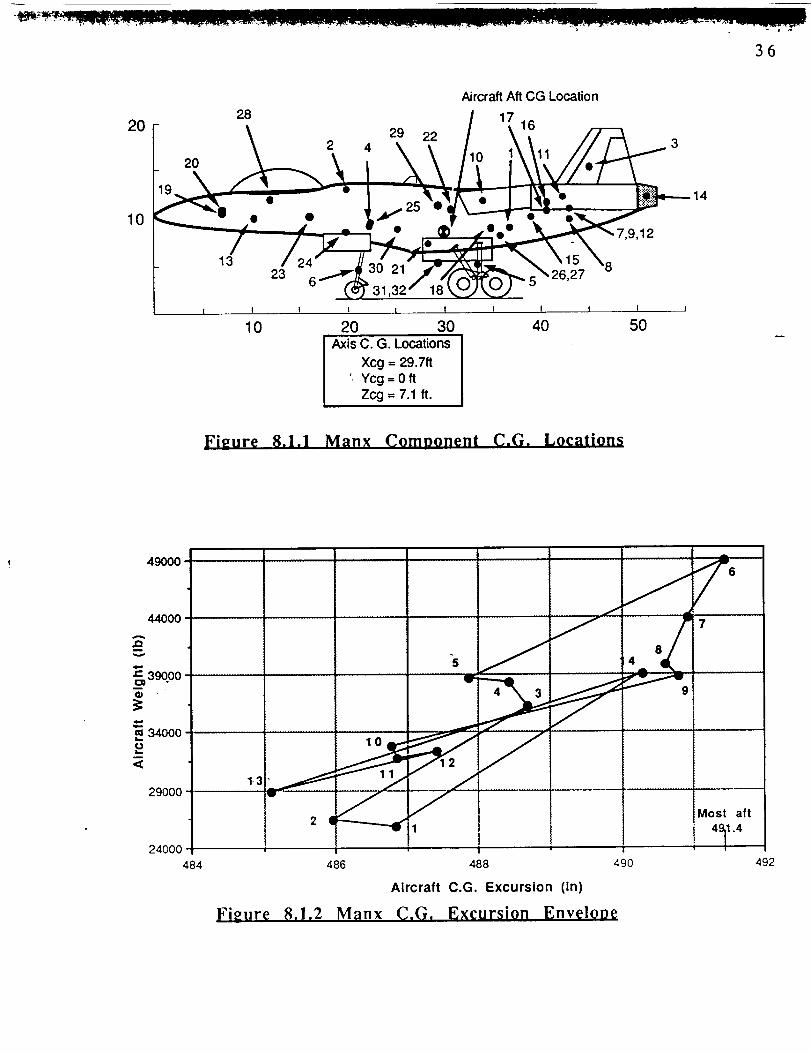
Table 8.1.1 lists the Manx component weights and individual locations
from the aircraft c.g. Component locations are presented visually in Figure
8.1.1. The longitudinal C.G. excursion for the range of loading conditions is
shown in Figure 8.1.2 and the corresponding mission phases are provided in
Table 8.1.2.
The C.G. travel as well as the tip-over angles of the Manx were found to
meet or exceed accepted limits according to guidelines listed in Reference 19
and are given as follows:
Acceptable Obtained
C.G. Range for Design Mission < 0.20c 0.05cLongitudinal Tip-Over Angle > 15 ° 23 °
Lateral Tip-Over Angle < 55 _' 55 °

35
Table 0.1.1 CoPzM3ormnt Wmtahts lind C.G. Locaflono
X,n_ YJJOJ ZCL0_
lm from fromno** _ around
1 wing 4850 443
2 canard 385 198
3 vertical tails 855 542
4 f_olaOe 5475 269
5 main gut 1235 386
6 n_e gear 665 230
7 engine mounts 143 5188 flmwal 116 518
9 engine Nctlon 106 518
10 Jr Inductt0fl syz 568 410
0.0
2@ ,,.-26.1
2@ *,-6920.0
2@ +-38.5-18.0
2@ ,,.-33.70.0
2@ ÷-33.7
2@ ÷-41.7
I Prooulsions
11 engines 4637 510
12 engine coolb_g 291 518
13 lumishtngs 385 126
14 taJ pip41s +, 52 602
15 oil ooo/_g 138 470
16 engine comm'- 73 49017 starlit 68 490
2@ ÷-33,7
2@ ÷-33.70J_
2@ +-33.7
0JO0_
0J)
89.2
125.0
150.0
91.743.3
37.5
112.799.2
112.7
108.3
112.7
112.7
101.7
117.0
I02.5
120.0
110.8
25800 J
IJsilul Load28 u'apped fue¥otl 244 474 O0 81.6
27 fuel 9855 366 O0 88.3
28 1:4ol 225 126 0.0 111.6
29 ammo 2106 354 (10 116.7
30 rnk_Mee 390 303 2@ .+316 87.5
31 12 bomb= 6060 382.5 12@ ¢g1.6 45.0
32 8 bombs 4040 364 2@±140 48.8
Tske-oH Weight
48820 I
Total Empty Weight
18 fuel $ys. & tam, s 477 420 0.0 88.3
19 IllgM a)mm_ 1031 86 0.0 108.420 bltrumentl 181 86 0.0 112-5
21 hydmutk:s 201 170 0.0 69.222 eleculcaJ 497 370 OD 111.6
23 iwtonim 1375 194 (10 103.2
24 gau-Sa cannon 1840 240 O0 IM.O25 air ¢ond/anU-l¢o 256 270 O0 96.0
36
20
10
Aircraft Aft CG Location
28
/ / q,z.L.F_.,I, .13 / 2At I I
23 "* _ 30 21 .,,_/_
| I I I t I I ! I I
10 20 30 40 50Axis C. G. Locations
Xcg = 29.7ft
'. Ycg = 0 ft
Zcg = 7.1 ft.
Figure 8.1.1 Manx Comoonent C.G. Locations
49000
44O0O
A
nv
Z- 39o00
m 34000
L,.
<
29000
24000
484
j/',
,o2 I
i , I486 488 490
i Most aft
: 4911.4
Aircraft C.G. Excursion (in)
Fieure 8,1.2 Manx C,G, Excursion EnvelorJe
492

1 Empty23456789
1011121314
Table 8.1.2 C.G. Excursion for Rang_e ofLoadinqs
Loading Condition
+TFO+Pilot+TFO+Pilot+Fuel+TFO+Pilot+Fuel+Ammo+TFO+Pilot+Fuel+Ammo+Missiles+TFO+Pilot+Fuel+Ammo+Missiles+Bombs
+TFO+Pilot+l/2Fuel+AmmQ+Missiles+Bombs+TFO+Pilot+l/2Fuel+Ammo+Missiles+l/2Bombs+TFO+PUot+l/2Fuel+l/2Ammo+Missiles+l/2Bombs+TFO+Pilot+l/2Fuel+l/2Ammo+Bombs+TFO+Pilot+l/2Fuel+Missiles+TFO+Pilot+l/2Fuel+l/2Ammo
+TFO+PUot+Ammo+Missiles+TFO+Pilot+Ammo+Missiles
Weight
(Ibs)
25,90026,36936,22438,33038,72048,82043,89339,85338,80031,68732,35028,86538,965
25r900
C.G. (in)
486.84485.95488.68488.43487.87
491.43490.92490.61490.79
486.77486.86
487.42485.09490.28
8.2 Mass Moments of Inertia
The aircraft moments of inertia were obtained using the guidelines in
Reference 21, and formulas for estimating the individual component inertias
were taken from References 34 and 35. The smallest components, totalling
under 4% of the full aircraft weight, were assumed to have negligible inertia
moments about their own C.G. and were therefore considered to be point
masses. The centroidal moments of inertia for the Manx when fully loaded for
the design mission are given below:
Ixx
lyy
Izz
Ixz
= 98,176 slug • ft2
= 144,200 slug • ft2
= 226,458 slug • ft 2
= 2,347 slug • ft2
....--_-_;_ - IIIII I II ........... = / .J ]1" ,, _ _'_v_"_"_."_- "Z_-''''':'
38
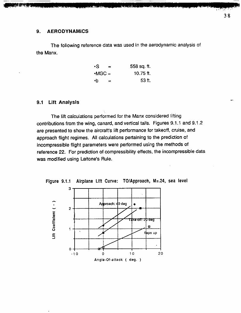
9. AERODYNAMICS
The following reference data was used in the aerodynamic analysis of
the Manx.
• S = 558 sq. ft.
• MGC = 10.75 ft.
•b = 53 ft.
9.1 Lift Analysis
The lift calculations performed for the Manx considered lifting
contributions from the wing, canard, and vertical tails. Figures 9.1.1 and 9.1.2
are presented to show the aircraft's lift performance for takeoff, cruise, and
approach flight regimes. All calculations pertaining to the prediction of
incompressible flight parameters were performed using the methods of
reference 22. For prediction of compressibility effects, the incompressible data
was modified using Laitone's Rule.
Figure 9.1.1
3
A
0
"-" 2
Q
b
Oo 1
J
Airplane Lift Curve: T0/Approach, M=.24, sea level
A_!
i , i i
)roach: 0 degi ....... L
/.4 J
Ke-O_: 2 J deg
J m
_j taps up
0 0
Angle-Of-attack ( deg. )
2O
......11--- _ II._ i'II I _J
39
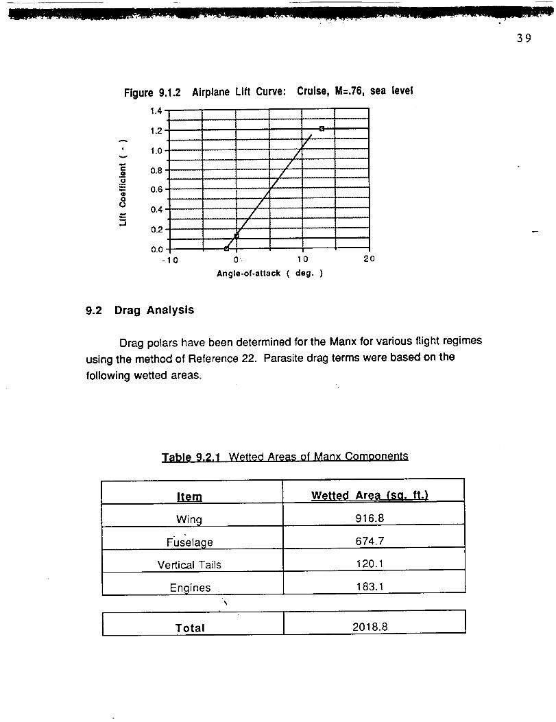
Figure 9.1.2 Airplane Lift Curve:
1.4
1.2
' 1.0
0.8Q
o
-- 0.6® lo /o 0.4= /
0.2 ._10.0
-10 0'.
Cruise, M=.76, sea level
r-
'" f
.................... ......
/
.......... • / I-
/
1
0
Angle-of-attack ( deg. )
20
9.2 Drag Analysis
Drag polars have been determined for the Manx for various flight regimes
using the method of Reference 22. Parasite drag terms were based on the
following wetted areas.
T_ll_le 9.2.1 Wetted Areas of Manx Comoonents
Item
Wing
FiJselage
Vertical Tails
Engines
Wetted Area (sq. ft.)
916.8
674.7
120.1
183.1
Total 2018.8

• . , '- ;
[] m
40
The drag for each component of the Manx was determined for various
flight regimes as seen in Figures 9.2.1- 9.2.4. Based on the performed profile
drag calculations and the skin friction coefficient of the aircraft taken as .004, the
Manx's equivalent flat plate area was computed to be 9.31 sq. ft. which places it
among similar aircraft of this type and helps to confirm the validity of the drag
polars presented. [6]
The influence of the canard vortices on the wing could not be accounted
for with the methods used in the computation of the drag polars. Accurate
prediction of the lift contributions due to vortex coupling must be determined
using either a computational fluid dynamics code or wind tunnel testing.
i
_Qf_
O
O
fJ
m
1.0
o.a ¸
0.6
0.4
0.2
0.0
0.0
4
i--;_;i:] i i]2_"
-
0.1 0.2 0.3
Drag Coefficient ( - )
0.4
Figure 9.2.1 Drag Polar: Take-off, M=.24, sea level

__-- Z_..-Z-- ........ _11 / III N /
41
1.0
|
eo
m
Q0
..I
0.8
0.6
0.4
..............................x ¸ ..... ciian __ " ......... -- " ______ _"f;
o.2 i/
: ,iio.o I L
0.0
_'._ ........\ ........_" • ......................................
_p_a=iu_.,,Tnfi!
/i
Figure 9.2.2
0.1 0.2 0.3
Drag Coefficient ( - )
Drag Polar: Approach, M=.24, sea level
1.2 r
0.4
1.0• :4 _.=0 t_O L
_ i'= .._,."-r .
v ...................
A .f_/. 0.8, _.t_-
¢g
"_ .,_L/ .11=- 0.6
o . . i I . ./L/, , .
o / P /!-.- (7/.J 0.4 _,- /
J/.l I _.i#'Fir f
i _- v i t J0.2 _.-i-_" i i j
IN! I J f • .o.o !,LI.! ,1.! ! 'I i 1
0.00
1
! ! .....
llj ........I t i .
0.05 0.10 0.15 0.20
Drag Coefficient ( - )
Figure 9.2.3 Drag Polar: Cruise, sea level

42
A
Emo
Qoo
_1
..... - • • • • T _ F
..... ' '1' | ! I E ____.t
1.0 ........................................ -'= .............s s .....
; "-; = _ /" kl-O. '6
r
0.4 _
r ,
0.2 ---J" J I J ] f J i I I ............! _ L i I ! 1......J
o.o I li
0.00 0.05 O. 10 O. 1 5 0.20
Drag Coefficient ( - )
Figure 9.2.4 Drag Polar: Cruise, 20,000 ft.
10, STABILITY AND CONTROL
After conducting a preliminary longitudinal and directional static stability
analysis an unstable static margin of -17.8 % was chosen for the Manx.
This level of instability will result in an aircraft that .meets or exceeds the
maneuverability characteristics of existing fighter aircraft. While having this
capability may mean higher complexity and cost, this added maneuverability
will enhance the aircraft's survivability as well as the plane's multi-role
capability and could thereby eliminate the need for specialized aircraft.
Furthermore, the Manx design team philosophy is designing for prevention
rather than cure. Therefore, the capability to out maneuver ground-to-air
ordinance and air-to-air interdiction is cost effective.
The Manx's relatively high level of instability requires the employment of
a stability augmentation system (SAS). Although a more costly flight control
system, the overall benefits it provides will outweigh the cost. The purpose of
SAS is to take an aircraft which is difficult or impossible to fly, and enable the

43
pilot to maneuver the aircraft to its fullest potential, while maintaining
work load. [12]A list of the stability derivatives follows in Table 10.1
a low pilot
Table 10.1. Static Stability Derivatives
Cy_ r 0.168 rad- 1
Cy_ v -0.393 rad- l
Cn6 r 0.036 rad- 1
0.084 rad- 1Cn[3v ,
Cn[3f -0.074 rad- 1
Cn_ w 0.0 rad- 1
Cnl 3 0.024 rad- 1
Cmi c 0.445 rad- 1
Cl._c 4.17 rad- 1
CLc_w f 3.72 rad- 1
CLa 4.23 rad- 1
11. Avionics
The avionics system of the Manx increases its effectiveness to deliver
close air support while at the same time being relatively simple thus decreasing
pilot workload. It is.assumed that the avionics will also be no more than 25% of
the total airplane cost.
The avionics were selected based on research conducted on existing
aircraft with similar mission capabilities [2]. It was determined that the Manx
requires the following avionics systems:

44
•Stability Augmentation System (SAS)
•Navigation (GPS)
•Terrain Following/Avoidance (Radar/IR)
•Target DetectTonand Identification
•Heads-up-display (HUD)
Due to the relaxed static stability of the Manx, a stability augmentation
system (SAS) in conjunction with fly-by-wire technology will be required. Hard
point accommodations will be provided for a ALQ-131 Electronics Counter
Measure (ECM) Pod, FLIR Pod and Low Altitude Navigation and Targeting withInfrared at Night (LANTIRN) pod. These avionics packages fulfill Manx's
navigation sensing requirements by providing night and adverse weather
operational capability by means of a terrain following radar (TFR) and a wide
angle forward looking infrared imaging system (FLIR) on a head-up display.The TFR and FLIR will also function to assist the Manx in effective target
detection, identification, and ordinance delivery. The design mission is
dominated by low level terrain, therefore a Global Positioning Satellite (GPS)
navigation system will be integrated to enhance the accuracy of the weapon
delivery and navigation. [33]
The following avionics components have also been included:
•Flight Control System
- flight computer- artificial horizon
- heading reference
- airspeed indicator\

=• _ III) r
45
•UHF/VHF antenna
.IFF transponder
•Central Air Data System
The triple-redundant flight computer will be utilized with the fly-by-wire
technology for signal transferring and multiplexing of the data. The air data
system should be integrated into the flight control system so that the engines
operate in the most efficient manner possible. A heads-up display (HUD)
system will utilize a CRT to prov!de a real time presentation of TFR and FLIR
information on range and angle tracking, real beam ground mapping, Doppler
beam sharpening, and target detection.
All of the avionics will be selected with Built-In-Test (BIT) capability to
reduce the maintenance and ground support requirements thus increasing its
suitability for remote site operations. For a description of BIT functioning, refer
to the Ground Support Requirements section of this report. [5]
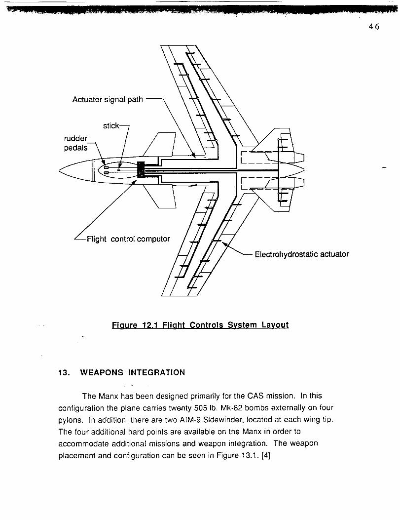
12. FLIGHT CONTROL SYSTEMS LAYOUT
The flight control system primary flight control system layout can be found
in Figure 12.1. The flight controls are irreversible. Signals are sent to the
actuator controller from the digital flight control computer through shielded lines.
The flight control computer is triple-redundant with second best information
reversion. The signal paths are double-redundant with the secondary paths
placed away from the primary paths for protection. There are two
electrohydrostatic actuators for each control surface and the control surfaces
are divided into at least two sections for redundance and safety.
I 1
46
Actuator signal path --
rudder
pedals
Flight control computor
Electrohydrostatic actuator
Figure 12.1 Flight Controls System Layout
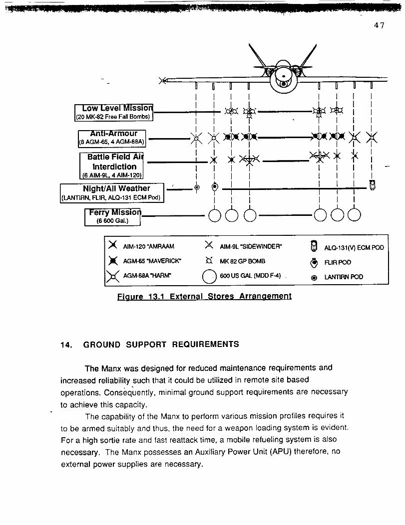
13. WEAPONS INTEGRATION
The Manx has been designed primarily for the CAS mission. In this
configuration the plane carries twenty 505 lb. Mk-82 bombs externally on four
pylons. In addition, there are two AIM-9 Sidewinder, located at each wing tip.
The four additional hard points are available on the Manx in order to
accommodate additional missions and weapon integration. The weapon
placement and configuration can be seen in Figure 13.1. [4]
4?
I Low Level Missior_(20 MK-82 Free Fall Bombs) I
Anti-Armour I(8 AGM-65, 4 AGM-88A)
Battle Field Ai_
Interdiction |i (6 AIM-9L 4 AIM-120) 1
Night/All WeatherLANTIRN,FLIR,ALQ-131ECMPod)
I I II I I I
I I
I FerryMissi°_ (_ (_ (_(6600Gal.) i
_I( AIM-120 "AMRAAM _(_ AIM-9L'SIDEWINDER" _ ALQ-131(V) ECM POD
X ,aM-=-_VER,C_" _ MK,2GPBOMB _ n.,RPO0
Fiqure 13.1 External Stores Arranoement
14. GROUND SUPPORT REQUIREMENTS
The Manx was designed for reduced maintenance requirements and
increased reliability such that it could be utilized in remote site based
operations. Consequentiy, minimal ground support requirements are necessary
to achieve this capacity.
The capability of the Manx to perform various mission profiles requires it
to be armed suitably and thus, the need for a weapon loading system is evident.
For a high sortie rate and fast reattack time, a mobile refueling system is also
necessary. The Manx possesses an Auxiliary Power Unit (APU) therefore, no
external power supplies are necessary.

111 IIl II _ IIllI i JL| _L JJ I
Inherent to the design of the Manx are built in features to assist in the
reduction of its ground support requirements. These come in the form of an On
Board Oxygen Generating System (OBOGS) and Jet Fuel Starting system (JFS)
which eliminate the need for separate starters and oxygen replenishment. In
addition, the Manx will carry self-sealing fuel lines, sealed batteries, and will
utilize electrohydrostatic actuators for all primary flight controls surfaces. Other
design features contributing to low maintenance include over wing engine
placement for reduced susceptibility to FOD and a hydraulic system that will
service only the landing gear for reduced chances of leakage. The lowered
FOD susceptibility is crucial for remote site based operations where runways
are difficult to maintain.
The ability of the Manx to provide effective close air support, however,
relies heavily on its on board avionics technology. As a result, the importance
that its avionics system be functioning properly with a high degree of reliability
and low maintenance can not be too highly stressed. For these reasons,
avionics systems will be selected with Built-In-Test (BIT) capability [5]. Avionics
systems provided with BIT will utilize the BIT capabilities of the avionics
equipment and multifunctional capabilities of the mission computer and CRT as
the primary mechanisms. Consequently, no special monitoring, storage, or
control equipment is required in providing:
• Complete operational readiness test capability without
equipment test sets
• In-flight periodic BIT fault detection and automatic
reversion to next best available data
• Initiated BIT fault isolation
• Complete functional test with repair verification
capability
The BIT capability is a key feature in keeping the aircraft in the air with minimal
ground support requirements so that its high sortie rate may be achieved.[5]

15. Life Cycle Cost Analysis
A life cycle cost analysis was performed for the Manx using the method in
Reference 23 which spans the program from its initial stages of research,
development, test, and evaluation to acquisition and manufacturing. This
analysis also includes operation, support, and disposal costs with all costs
expressed in 1992 dollars.
The research, development, test, and evaluation (RDTE) phase consists
of aircraft's planning and conceptual design. It is during this phase that the
aircraft's mission requirements research is conducted and preliminary design
activities performed. Also during this phase, trade studies are performed to
assess what combinations of technology are important to the aircraft's
performance. The final leg of this phase consists of systems integration,
detailed design, and prototype testing involving flight and structural testing. It
was assumed that due to the nature of military contracts, the Manx will be a high
security program and as such will have a slightly higher cost in this phase for
security reasons. The RDTE cost was computed as being a function of airframe
engineering and design costs, development support and testing cost, flight test
and operations cost, test and simulation facilities cost, RDTE profit, and costs to
finance the RDTE phase.
The programs acquisition costs include the manufacturers cost with a
10% profit margin for 500 aircraft. This cost is defined as arising from airframe
engineering and design, airplane production, flight test operations, and the
financing of the manufacturers program. During the programs duration, costs
from operations arising from fuel, oil, and lubricants, aircrew, maintenance
crews, and other associative direct and indirect personnel have been allotted
for as well as spares, depots, and miscellaneous expenses. Finally, the
disposal phase has been predicted assuming the life cycle of the aircraft will run
25 years.
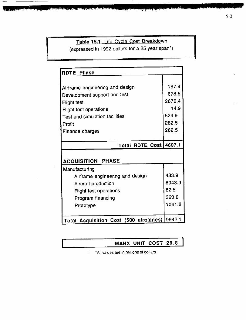
Table 15.1 present a breakdown of these associative costs and the Manx
unit cost. The calculated operational cost is $1549 per flight hour. Figure 15.2
shows a qualitative beakdown of how the life cycle cost is comprised.
5O
T_ble 15.1 Lif_ Cycle Cost Breakdown
(expressed in 1992 dollars for a 25 year span*)
RDTE Phase
Airframe engineering and design
Development support and test
Flight test
Flight test operations
Test and simulation facilities
Profit
Finance charges
Total RDTE Cost
187.4
678.5
2676.4
14.9
524.9
262.5
262.5
4607.1
ACQUISITION PHASE
Manufacturing
Airframe engineering and design
Aircraft production
Flight test operations
Program financing
Prototype
Total Acquisition Cost (500 airplanes)
433.9
8043.9
62.5
360.6
1041.2
9942.1
ii lu MANX UNIT COST
"Allvalues are in millions of dollars.
28.8

5!
[] Airframe eng. design cost
[] Development support and test
[] Flight test
[] Flight test ops for prototypes[] Test and simulations
[] Profit
[] Finance charges
[] Manufacturing eng. and desigr
[] Aircraft production
[] Flight test ops[] Program financing
[] Prototype
Figure 15.1: Life Cycle Cost Breakdown
16. Conclusions and Recommendations
The Manx is an advanced, high performance design capable of meeting
the needs of a close air support fighter that will operate into the twenty first
century. The design of the aircraft incorporates proven technologies giving it
unmatched capabilities in maneuverability and survivability with relatively low
maintenance requirements enhancing its suitability for the close air support
role. The design is flexible allowing it to contribute to a truly integrated ground
team capable of rapid deployment from forward sites making it highly attractive
in the third world theatre, while increasing its chances of acceptance as a Navy
based fighter.
The Manx has the capacity to outperform the aging Fairchild A-10. It can
perform the close air support mission at higher speeds, carrying a greater
payload, having lower take-off and landing distances, and excellent
maneuvering qualities which enable it have a limited air-air interdiction

52
capacity. In short, it has all of the necessary qualities to make it the obvious
replacement aircraft.With the completion of the preliminary design, there are still areas which
require further research as listed below:
• Thrust vectoring capabilities
• Integration of HIDEC (Highly Integrated Digital Engine Control)
Optimization of the engine for efficient
Optimization of, the flight computer
high speed cruise
• Structural analysis of the composite structure of the wing
Further analysis in these areas is suggested to complete the design
process for the Manx. Equipped with these additional capabilities, the Manx will
be a formidable force to contend with in the twentieth century.

53
REFERENCES
°
o
o
.
o
o
o
8.
°
10.
11.
12.
13.
14.
Roskam, J., Airplane Design Part 1:Preliminary Sizing of Airolanes,Roskam Aviation and Engineering Corporation, Route 4, Box 274,Ottawa, Kansas
Taylor, J. W. R., editor, Jane's All the World's Aircraft 1986 - 87. JanesPublishing Co. Lmtd, New York
Meeks, T. M., Advanced Technology Integration for Tomorrows FighterAircraft, AIAA - 86 - 2613, October 1986
Abbot and Von Doenhoff, Theory_ of Wing Sections, Dover Publications,Inc., New York
a
Anderson, R. J., "AV - 8B Design for Maintainability", technical paper0149-144X10000-0028, October 1985
Bertin and Smith, Aerodynamics for Engineers, Prentice Hall, EnglewoodCliffs, New Jersey
Anderson, J. D., Fundamentals of Aerodynamics, McGraw-Hill, Inc. 1984
Raymer, D. P., Aircraft design: A Conceotual A ooroach, AIAA, Inc.Washington, D.C.
Taylor, J. W. R., editor, Jane's All the Wodd's Aircraft 1990-91, Jane'sInformation Group Limited, Virginia
Roskam, J., Airplane Flight Dynamics and Automatic Flight Controls,Roskam Aviation and Engineering Corp., Kansas
Lennon, A., Canard: A R_vQIution in Flight, AViation Publishers Division,PA
Nelson, R. C., Flight Stability and Automatic Control, McGraw-Hill, Inc.1989
Re, R. J., "Longitudinal Aerodynamic Characteristics of a Fighter Modelwith Close-coupled Canard at Mach numbers from 0.4 to1.2", NASAtechnical paper; 1206, Washington, D.C. "
Gainer, T. G., "Low-speed Investigation of Effects of Wing Leading- andTrailing-edge Flap Deflections and Canard Incidence on a Fighter
Configuration Equipt with a Forward-swept Wing", NASA technicalmemorandum, Washington, D.C.

15. Phillips, J. D., "Approximate Neutral Point of a Subsonic Canard Aircraft",NASA technical memorandum, Moffett Field, CA
16.
•_ 18.
19.
20.
21.
22.
23.
24.
25.
26.
27.
Gloss, B. B., "Effect of Canard Vertical Location, Size, and Deflection onCanard- wing interference at Subsonic Speeds", NASA technicalmemorandum; 78790
Roskam, J., Aimlane Design Part I1: Preliminary_ Configuration Designand Integration of the Propulsion System, Roskam Aviation andEngineering Corp., Route 4, Box 274, Ottawa, Kansas
Roskam, J., Airolane Design Part II1: Layout Design of Cockoit. Fuselage.Wine and EmDennage: Cutaways and Inboard Profiles, Roskam Aviationand-Engineering Corp., Route 4, Box 274, Ottawa, Kansas
Roskam, J., Airolane Desien Part IV: Layout Design of Landing Gear andSystems, Roskam Aviation and Engineering Corp., Route 4, Box 274,Ottawa, Kansas
Roskam, J., _,imlane Design Part V: Com0onent Weight Estimation,Roskam Aviation and Engineering Corp., Route 4, Box 274, Ottawa,Kansas
Roskam, J., Airolane Design Part VI: Preliminary Calculation ofAerodynamic. Thrust and Power Characteristics, Roskam Aviation andEngineering Corp., Route 4, Box 274, Ottawa, Kansas
Roskam, J., AirplsnQ Design Psrt VII: Determination of Stability. Controland Performance Characteristics: FAR and Military Reauirements,Roskam Aviation and Engineering Corp., Route 4, Box 274, Ottawa,Kansas
Roskam, J., Airolane Design Part VIII: Air olane Cost Estimation: Design.Development. Manufacturing and Ooeratina, Roskam Aviation andEngineering Corp., Route 4, Box 274, Ottawa, Kansas
Zucrow, M. J. and Hoffman J.D., _as Dynamics Vol. 1, John Wiley andSons, New York 1876
gates, G.C., editor, Aergthermodvnami¢_ of Aircr_f_ Engine Comoonents,AIAA, Inc., New York 1985
Oatesl G. C., editor, Aerothermodynamics of Gas Turbine and Rocket
ProDulsion Revised and enlarged, AIAA Inc., New York 1988
Anderson, J. D. Jr., Irltroduction TO Fliqht, McGraw-Hill, Inc 1985
Engine data package, Addendum to Reference 32
55
30.
31.
32.
33.
34.
35.
Shirfin, C. A., "Eurofighter Partners Use Many Advanced Materials toKeep EFA's Weight Down", Aviation Week and Space Technology / April15 1991
Hoak, C. E., editor, USAF Datcom, Air Force Flight Dynamics Laboratory,Wright Patterson Air Force Base, Ohio
1990 AIANGeneral Dynamics Gr.oup Student Design Competition -Undergraduate, Request for Proposal
Sweetman, Bill, editor, The Great Book of Modern Warplanes, PortlandHouse, New York, 1987
Hibbeler, R. C., Engineering Mechanics, Macmillan Publishing CI., Inc.,New York
Gianocoli, D. C., General Physics. Prentice-Hall, Inc., Englewood Cliffs,New Jersey