matsushita - electrozep :: romaniaelectrozep.ro/documentatie/panasonic,sunx,nais,ma… · ·...
TRANSCRIPT

Matsushita
PROFIBUS
2
PROFIBUSAdvantages
With NAiS PROFIBUS DP and FMS, Matsushita offersthe user a powerful program for communication at theintermediate and lower hierarchy levels.
Certification ensures open communication betweenNAiS PROFIBUS units and PROFIBUS devices providedby other manufacturers. This is guaranteed by EuropeanStandard EN 50170.
PROFIBUS is an established and well proven multi-purpose field bus worldwide, for plantwide use in all industries. Many leading automation companies usePROFIBUS technology.
PROFIBUS is both fast and efficient. The modularity makes its use quick and reliable.
A wide range of diagnostic options and error handlingfacilities is available.
With PROFIBUS no additional costs are incurred forserial interface adapters for a range of differentdevices.
PROFIBUS FMS (Fieldbus Message Specification)
...is the solution optimized for cell level factory automation andmulti-master applications, also for building automation. FMSoffers comprehensive user services - known as FMS services- for writing and reading variables, starting and stoppingprogrammes, events management and management services.
PROFIBUS DP (DECENTRAL PERIPHERY)
...is the most commonly used profile. It is a very robust systemavailable for discrete manufacturing and process controlbecause it offers substantial I/O capability, fast speed andlong transmission distances. PROFIBUS DP has a decentra-lised I/O protocol arranged for cyclic data exchange.
Matsushita can supply a combined NAiS FMS / DP master.
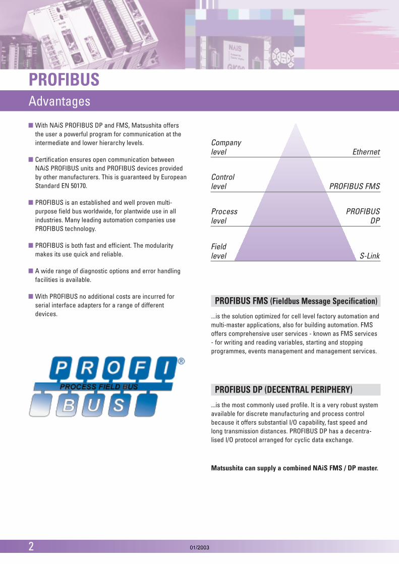
Companylevel Ethernet
Controllevel PROFIBUS FMS
Process PROFIBUSlevel DP
Fieldlevel S-Link

PROFIBUSProduct Overview
3
FP2FMSDPM Page 4PROFIBUS FMS/DP Expansion Unit for the FP2 Series PLCsIdeal for extensive high-level multi-master networks.
FP2DPM Page 5PROFIBUS DP Master Expansion Unit for the FP2 Series PLCsIdeal for cost-effectiv control of destributed field devices.
FP0DPS2 Page 6A DIP switch allows you to select betweenPROFIBUS DP Slave or PROFIBUS remote I/O.
The PROFIBUS DP Slave Unit connects Matsushita’s micro PLCs FP0 and FP∑ (Sigma)to a PROFIBUS network as a slave.
PROFIBUS Remote I/O Unit Page 7-9connects I/Os at remote locationsvia PROFIBUS.
GK-IFC-PB Page 10-11PROFIBUS DP Interface card for GK Series Key Terminalsallows cyclical and problem-free networking of numerous devices.
BFVC9901 and BFVC9902 PROFIBUS DP communication module Page 12for the VF-CE Series Inverter connects Matsushita’s VF-CE inverterto a PROFIBUS network as a slave.
9-pin SUB-D connectors Page 13are used to connect stations to PROFIBUS.
PROFIBUS Accessories
Inverter PROFIBUScommunication module
HMI PROFIBUS Interface Card
PROFIBUS Remote I/O Unit
FP0 DP Slave Unit
FP2 DP Master Unit
FP2 FMS/DP Master Unit

4
FP2 PROFIBUSFMS / DP Master Unit
The FP2 FMS/DP master unit supports simultaneous operation of PROFIBUS FMS and DP.This combined master unit operates at rates of up to 12 Mbaud.
FP2FMSDPM: FP2 FMS/DP Master UnitTechnical dataType designation FP2 FMS/DP Master Unit, Ord. No. FP2FMSDPMPROFIBUS standards complied with EN 50170, DIN 19245 Part 1, Part 2, Part 3Baud rates 9.6 / 19.2 / 93.75 / 187.5 / 500 / 1,500 / 3,000 / 6,000 / 12,000 KbaudNumber of open connections 64Max. no. of PROFIBUS master units 1per CPUMax. input/output data 238 Bytes / slavePROFIBUS connection 9-Pin D-sub connectorMax. power consumption (5V) 500mAOperating temperature range 0 ... 55°CStorage temperature -20 ... 70°CMax. humidity 30% ... 85% (non-condensing)Vibration resistance 10Hz to 55Hz, 1 cycle per minute with double amplitude 0.75mm; 10 min. per X , Y and Z axisShock resistance min. 98m/s2; 4 times per X, Y and Z axisDimensions (mm) 28 x 100 x 90 (WxHxD)Operating conditions free from corrosive gases and excessive dust contaminationCE regulations EMC Guideline 89/336/EEC 1989
- EN50081-2: 1993- EN50082-2: 1995
FMS object and data typesObject types Data typesNull Object Integer 8Data Type Integer 16Simple Variable Integer 32Array Unsigned 8OD-Object Description Unsigned 16
Unsigned 32Floating PointOctet StringVisible String
Connection typesMMAZ Master-master acyclicMSAZ Master-slave acyclicMSZY Master-slave cyclicMulticast, Broadcast
FMS servicesService Controller class 3Initiate XAbort XStatus XReject XIdentify SGet OD SInitiate Put OD SPut OD STerminate Put OD SRead XWrite X
X: Client and serverS: Server only
The data for Profibus DP mode are identical with FP2DPM.

FP2 PROFIBUSDP Master Unit
5
FP2 PROFIBUS DP master unit links Matsusihita’s powerfulFP2 controllers with a wide variety of distributed field devices.Designed for high-speed I/O communication, it is especiallysuited to time-critical applications.
The DP master unit allows the FP2 controller to communicatewith the devices installed in the PROFIBUS network and tocontrol slave devices. This unit supports baud rates of up to12 Mbaud.
FP2DPM: FP2DP-Master UnitTechnical dataType designation FP2 DP Master Unit, Ord. No. FP2DPMPROFIBUS standards complied with EN 50170, DIN 19245 Part 1, Part 3Baud rates 9.6 / 19.2 / 93.75 / 187.5 / 500 / 1,500 / 3,000 / 6,000 / 12,000 KbaudMax. no. of PROFIBUS slave units 125Max. no. of PROFIBUS master units per CPU 1Max. input/output data 238 bytes / slavePROFIBUS services The following PROFIBUS-DP master services are supported:
Dat_Exchange, Slave_Diag, Set_Prm, Chk_Cfg, Global_Control (sync, freeze, clear), Get_Master_Diag, Start_Seq, Download, Upload, End_Seq, Act_Para_Brct
PROFIBUS connection 9-pin D-sub connectorMax. power consumption (5 V) 500mAOperating temperature range 0 ... 55°CStorage temperature -20 ... 70°CMax. humidity 30% ... 85% (non-condensing)Vibration resistance 10Hz to 55Hz, 1 cycle per minute with double amplitude 0.75mm; 10 min. per X , Y and Z axisShock resistance min. 98m/s2; 4 times per X, Y and Z axisDimensions (mm) 28 x 100 x 90 (WxHxD)Operating conditions free from corrosive gases and excessive dust contaminationCE regulations EMC Guideline 89/336/EEC 1989
- EN50081-2 : 1993- EN50082-2 : 1995

6
FP0 / FP∑ (Sigma) PROFIBUSDP Slave Unit
Specifications of the FP0DPS2 unit in DP Slave modeTechnical dataType designation FP0 DP Slave unit, Ord. No. FP0DPS2PROFIBUS standards complied with EN 50170, DIN 19245 Part 1 and Part 3Baud rates 9.6 / 19.2 / 93.75 / 187.5 / 500 / 1,500 / 3,000 / 6,000 / 12,000 Kbaud
automatic baud rate detectionRange of addresses that can be set 0...125PROFIBUS connection 9-pin D-sub connectorFP0 communication Via FP0 system busConfiguration 2 words input / 2 words output up to 6 words input/6 words output if no other expansion is connectedPower supply 24VDC (21.6VDC … 26.4VDC)Max. power consumption 100mAOperating temperature range 0 ... 55°CStorage temperature -20 ... 70°CMax. humidity 30% ... 85% (non-condensing)Vibration resistance 10Hz to 55Hz, 1 cycle per minute with double amplitude 0.75mm; 10 min.per X , Y and Z axisShock resistance min. 98m/s2; 4 times per X, Y and Z axisDimensions (mm) 25 x 90 x 60 (WxHxD)Operating conditions free from corrosive gases and excessive dust contaminationCE regulations EMC Guideline 89/336/EEC 1989
- EN50081-2 : 1993- EN50082-2 : 1995
The FP0 DP slave unit allows Matsushita’s micro FP0 or FP∑ (Sigma)controller to be connected to PROFIBUS DP as a slave unit. The FP0has its own powerful set of commands and operates independently.
In the PROFIBUS network the FP0 and FP∑ (Sigma) are intelligentremote slaves and can even continue the control function safely iffieldbus communication is interrupted.
A DIP switch allows the user to select between: FP0 DP Slave or (see below) PROFIBUS remote I/0 unit (see next page)
FP0 / FP∑ (Sigma) PROFIBUSRemote I/O Unit
7
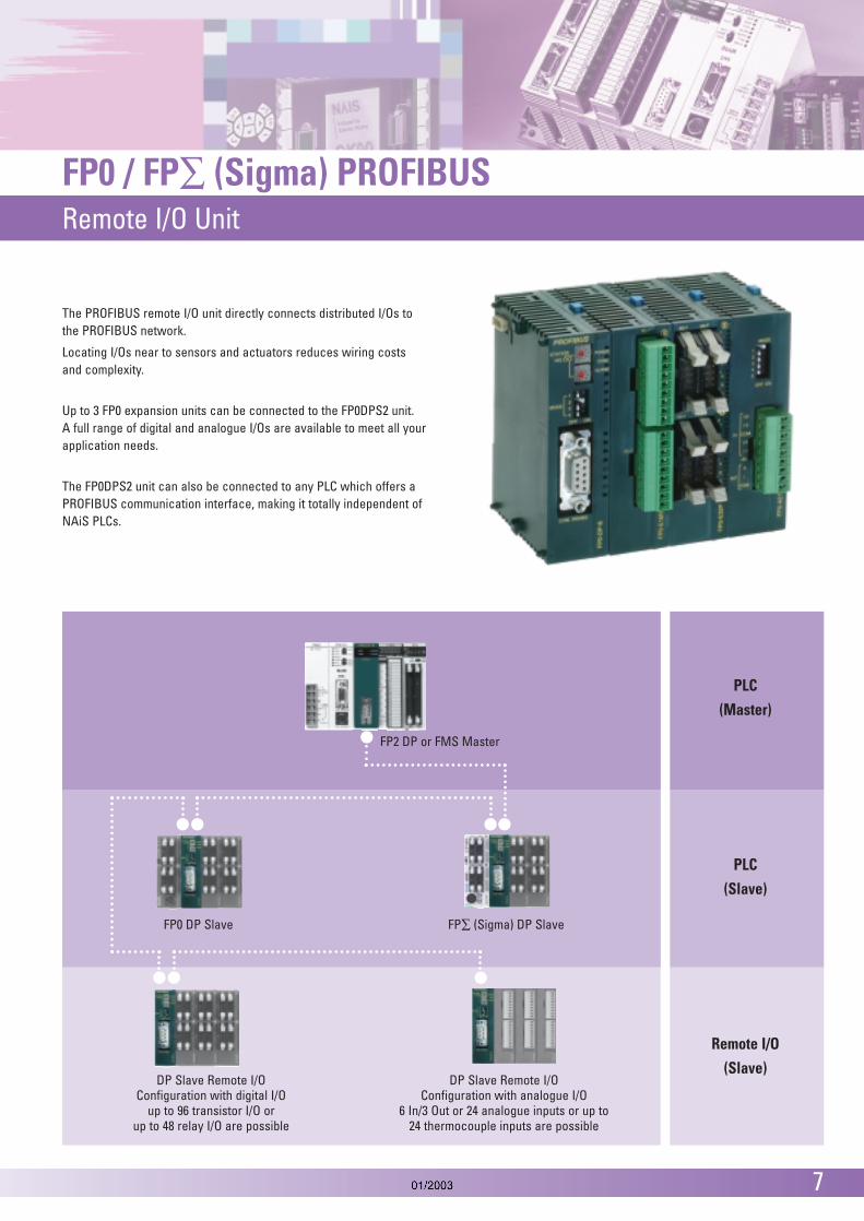
The PROFIBUS remote I/O unit directly connects distributed I/Os tothe PROFIBUS network.
Locating I/Os near to sensors and actuators reduces wiring costsand complexity.
Up to 3 FP0 expansion units can be connected to the FP0DPS2 unit.A full range of digital and analogue I/Os are available to meet all yourapplication needs.
The FP0DPS2 unit can also be connected to any PLC which offers aPROFIBUS communication interface, making it totally independent ofNAiS PLCs.
PLC(Master)
PLC(Slave)
Remote I/O(Slave)
FP0 DP Slave FP∑ (Sigma) DP Slave
DP Slave Remote I/OConfiguration with digital I/O
up to 96 transistor I/O orup to 48 relay I/O are possible
DP Slave Remote I/OConfiguration with analogue I/O
6 In/3 Out or 24 analogue inputs or up to24 thermocouple inputs are possible
FP2 DP or FMS Master

8
PROFIBUS Remote I/O UnitA maximum of 3 expansion units can be added
Transistor output type
Digital I/O Units
Relay output type Input only type
Terminal typeTerminal type
8 pointsInput
8 points
16 pointsInput
16 points
8 pointsInput
4 points
Option:
Output 8 points
Output4 points
16 pointsInput
8 pointsOutput8 points
NPN output type
PNP output type
NPN output type
PNP output type
NPN output type
PNP output type
NPN output type
PNP output type
8 pointsInput
8 points
16 pointsInput
8 pointsOutput8 points
16 pointsOutput
16 points
32 pointsInput
16 pointsOutput
16 points
Analogue I/O Units Thermocouple Units
8 points3 points
Input 8 points
Terminal type
• analogue input: 10V, 0 – 5V, 0 – 20mA
• analogue output: 10V, 0 – 20mA
• resolution: 12 bits
• analogue input: 10V, 100mV0 – 5V, 0 – 20mA
• resolution: 12 bits
4 points
Input4 points
8 points
Input8 points
• K, J, T, R type thermocouples canbe used
• Resolution: 0.1 °C• Accuracy: 0.8 °C (R type: 3 °C• Temperature range: -100 to 500 °C
Input 2 points
Terminal type
Output 1 point
FP0 DPS2 Expansionunit
Expansionunit
Expansionunit
(Maximum possible expansion is three units)
The expansion unit can be attached easilywithout any cables.
Up to 3 expansion units can be connected to the PROFIBUSremote I/O unit. Special expansion cables, backplanes, andso forth, are unnecessary as the expansion unit employs astacking system that uses expansion connectors and locklevers on the surface of the unit itself.
Easy Expansion
AC Power Supply
FP0-PSA2
Input85 to 265VAC
Terminal type
Output24DC/0.7A

PROFIBUS Remote I/O UnitSpecifications
9
Specifications of the FP0DPS2 unit in remote I/O modeType designation FP0DPS2PROFIBUS standards complied with EN 50170, DIN 19245 Part 1 and Part 3Baud rates 9.6 / 19.2 / 93.75 / 187.5 / 500 / 1,500 / 3,000 / 6,000 / 12,000 Kbaud
automatic baud rate detectionRange of addresses that can be set 0...125PROFIBUS connection 9-pin D-sub connectorConfiguration Remote I/O, max. 3 FP0 Expansion UnitsPower supply 24 VDC (21.6 VDC … 26.4 VDC)Max. power consumption 100 mAOperating temperature range 0 ... 55 °CStorage temperature -20 ... 70°CMax. humidity 30% ... 85% (non-condensing)Vibration resistance 10Hz to 55Hz, 1 cycle per minute with double amplitude 0.75mm; 10 min.per X , Y and Z axisShock resistance min. 98m/s2; 4 times per X, Y and Z axisDimensions (mm) 25 x 90 x 60 (WxHxD)Operating conditions free from corrosive gases and excessive dust contaminationCE regulations EMC Guideline 89/336/EEC 1989
- EN50081-2 : 1993- EN50082-2 : 1995
10
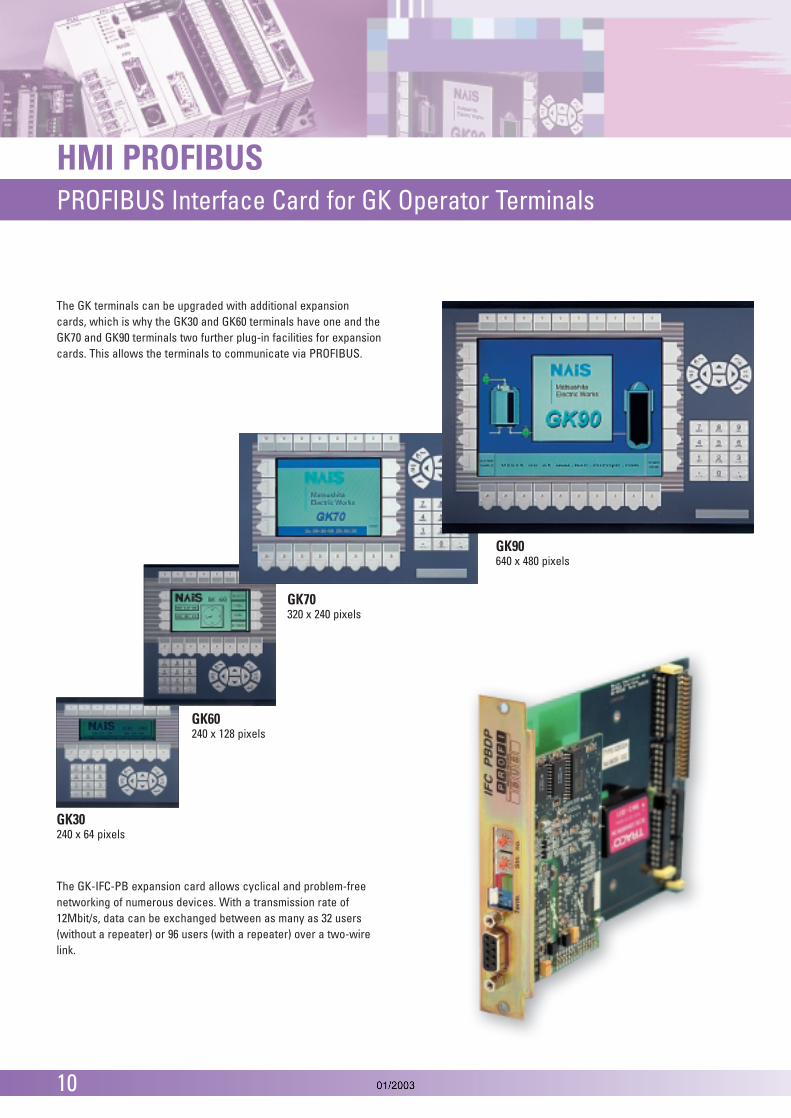
HMI PROFIBUSPROFIBUS Interface Card for GK Operator Terminals
GK90640 x 480 pixels
GK70320 x 240 pixels
GK60240 x 128 pixels
GK30240 x 64 pixels
The GK-IFC-PB expansion card allows cyclical and problem-freenetworking of numerous devices. With a transmission rate of12Mbit/s, data can be exchanged between as many as 32 users(without a repeater) or 96 users (with a repeater) over a two-wirelink.
The GK terminals can be upgraded with additional expansioncards, which is why the GK30 and GK60 terminals have one and theGK70 and GK90 terminals two further plug-in facilities for expansioncards. This allows the terminals to communicate via PROFIBUS.

HMI PROFIBUSPROFIBUS Interface Card for GK Operator Terminals
11
Part Number Power consumptionTransmission rate
ProtocolData transferField bus standardMax. number of nodes without repeaterMax. nodes with repeaterMax. cable length with repeaterMax. cable length without repeaterConnection typeTerminationAmbient temperature Storage temperatureAmbient humidityStorage humidityInsulation resistance Vibration resistance
Shock resistance EMCWeight
GK-IFC-PB internal via GK terminals9.6 / 19.2 / 93.75 / 187.5 / 500kBit/s; 1.5 / 3 / 6 / 12Mbit/sautomatic baud rate detectionPROFIBUS DP200 bytes when transmitting and receivingEN50170 volume 232963,000m / 9.6kbits200m / 12MbitsD-Sub and screw connectionsDIP switch0 to + 70°C-20 to +70°C30 to 85% RH (non-condensing)30 to 95% RH (non-condensing)100MΩ or more between external terminals ans GND corresponds to IEC 68-2-6 (test Fc.)and IEC 68-2-64 (test Fh.)10g, 4 x on 3 axesEN50081-2 and EN50082-20.3kg
Technical Specifications
Installing the expansion cards
Card inslot 2
Card inslot 1
Slots for the expansion cards
e. g. GK70
The expansion cards are connected to the CPU ofthe terminal via a parallel interface.
There are 1 or 2 slots for the expansion cards on the back of the GKterminals.GK30 / GK60: 1 slot GK70 / GK90: 2 slots
12
Inverter PROFIBUSPROFIBUS Interface Modules for VF-CE Inverter
• Ultra-compact• Integrated filter with EMC interference to class B• Vector control and V/f control• Up to 1.8 x MN torque for 60s (MN = rated load torque)• Multiple interfaces
(digital/analogue - I/O, RS232/RS485, PROFIBUS)• Operator module with copy function
• International approvals (CE, UL, cUL)• Cost effective• Energy efficient
• Types: 1-phase 230VAC: 0.25 to 2.2kW(1-phase 115VAC: 0.12 to 0.18kW)3-phase 400VAC: 0.75 to 4.0kW(3-phase 200VAC: 0.75 to 2.2kW)
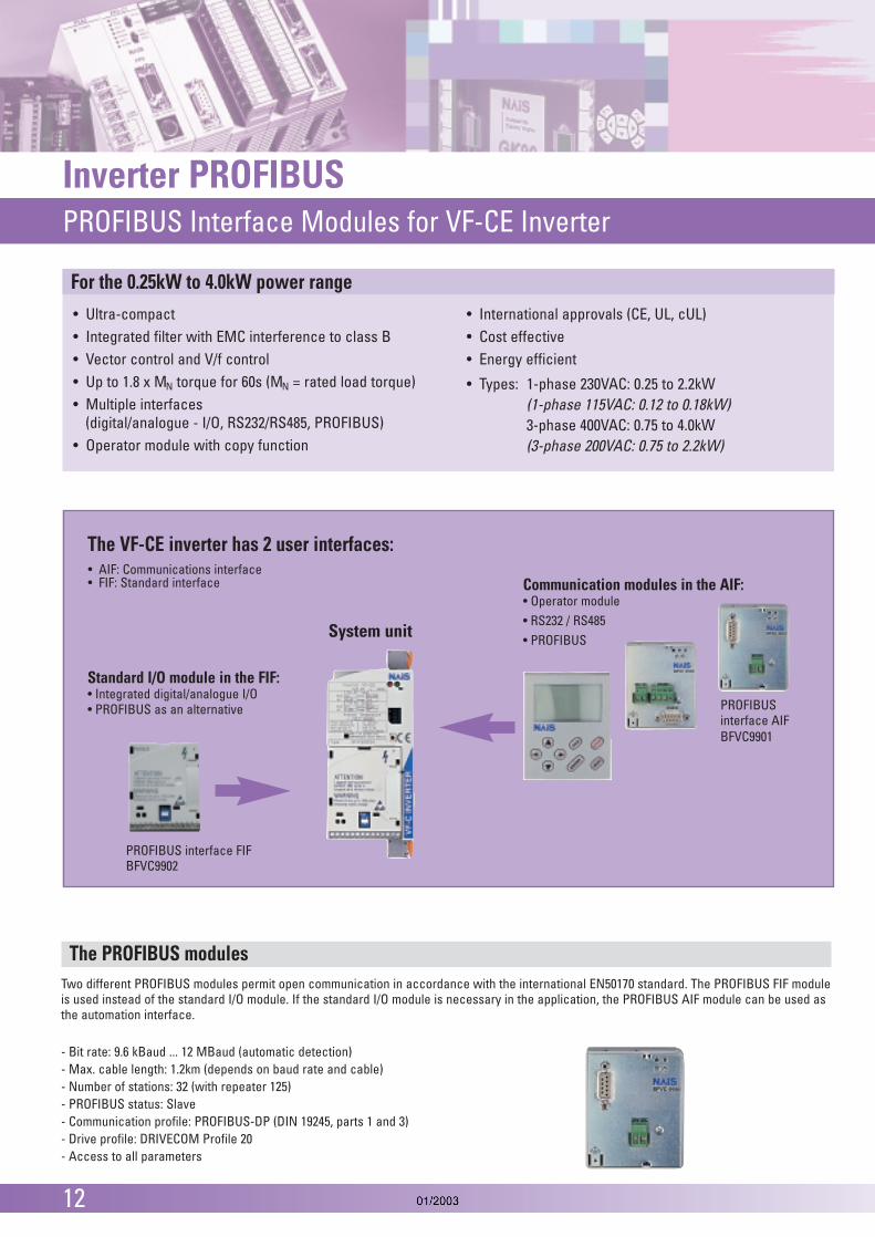
The VF-CE inverter has 2 user interfaces:
Communication modules in the AIF: • Operator module• RS232 / RS485• PROFIBUS
Standard I/O module in the FIF:• Integrated digital/analogue I/O• PROFIBUS as an alternative
System unit
For the 0.25kW to 4.0kW power range
• FIF: Standard interface• AIF: Communications interface
PROFIBUS interface FIFBFVC9902
PROFIBUSinterface AIFBFVC9901
The PROFIBUS modulesTwo different PROFIBUS modules permit open communication in accordance with the international EN50170 standard. The PROFIBUS FIF moduleis used instead of the standard I/O module. If the standard I/O module is necessary in the application, the PROFIBUS AIF module can be used asthe automation interface.
- Bit rate: 9.6 kBaud ... 12 MBaud (automatic detection)- Max. cable length: 1.2km (depends on baud rate and cable)- Number of stations: 32 (with repeater 125)- PROFIBUS status: Slave- Communication profile: PROFIBUS-DP (DIN 19245, parts 1 and 3)- Drive profile: DRIVECOM Profile 20- Access to all parameters
PROFIBUS Accessories Connectors and Cables
13
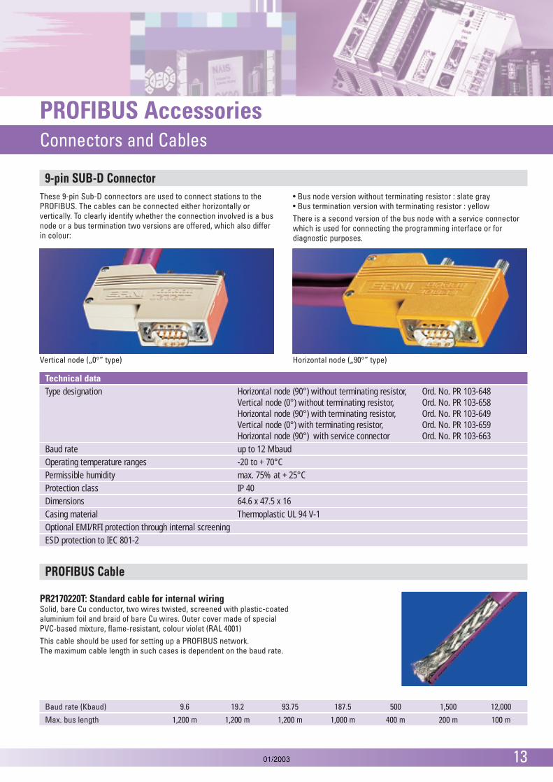
Vertical node („0°“ type) Horizontal node („90°“ type)
These 9-pin Sub-D connectors are used to connect stations to thePROFIBUS. The cables can be connected either horizontally orvertically. To clearly identify whether the connection involved is a busnode or a bus termination two versions are offered, which also differin colour:
• Bus node version without terminating resistor : slate gray• Bus termination version with terminating resistor : yellowThere is a second version of the bus node with a service connectorwhich is used for connecting the programming interface or fordiagnostic purposes.
9-pin SUB-D Connector
Technical dataType designation Horizontal node (90°) without terminating resistor, Ord. No. PR 103-648
Vertical node (0°) without terminating resistor, Ord. No. PR 103-658Horizontal node (90°) with terminating resistor, Ord. No. PR 103-649Vertical node (0°) with terminating resistor, Ord. No. PR 103-659Horizontal node (90°) with service connector Ord. No. PR 103-663
Baud rate up to 12 MbaudOperating temperature ranges -20 to + 70°CPermissible humidity max. 75% at + 25°C Protection class IP 40Dimensions 64.6 x 47.5 x 16Casing material Thermoplastic UL 94 V-1Optional EMI/RFI protection through internal screeningESD protection to IEC 801-2
Baud rate (Kbaud) 9.6 19.2 93.75 187.5 500 1,500 12,000
Max. bus length 1,200 m 1,200 m 1,200 m 1,000 m 400 m 200 m 100 m
PR2170220T: Standard cable for internal wiringSolid, bare Cu conductor, two wires twisted, screened with plastic-coatedaluminium foil and braid of bare Cu wires. Outer cover made of specialPVC-based mixture, flame-resistant, colour violet (RAL 4001)This cable should be used for setting up a PROFIBUS network.The maximum cable length in such cases is dependent on the baud rate.
PROFIBUS Cable

14
PROFIBUS ConfiguratorConfiguration software for PROFIBUS FMS
PROFIBUS FMS ConfiguratorThe FMS configurator software allows user-friendly configuration of aPROFIBUS FMS network. This software supplies the necessary parametersfor an individual network.
The editors of the FMS configurator support the following functionalities:
Device functionality
Network topology
Logical device connections: Communication links
Communication objects
Object directories
Bus parameters
To configure the PROFIBUS you will need the PROFIBOARD which connectsthe PC to PROFIBUS in your computer.
Devices from different suppliers can be connected to the PROFIBUS. The configurator software is needed to set the parameters in thePROFIBUS network in order that these devices can communicate with each other.
PROFIBUS Tool
The PROFIBUS TOOL is delivered with the FMS Configurator and is used to:
1. set the:
COM port of the PC which is connected to the PLC
baud rate for data transfer between PC and PLC
connected PLC type
baud rate of the PROFIBUS unit
PROFIBUS address and
slot no. of the PROFIBUS unit
2. convert the CNF file (configuration file) which is provided by theconfigurator into a List of Global Variables (ASC file) You can import the ASC file into you PLC program in order to makevariables available for the PLC program in NAiS Control

PROFIBUS ConfiguratorConfiguration software for PROFIBUS DP
15
PROFIBUS DP Configurator The DP configurator software:
imports third-party provided device descriptions as DDB files (in Germanyusually referred as GSD) to add to the device description database, removeand update DDB files in the device description database
creates and edits configuration projects by adding, changing and deletingdevice descriptions for the master and the slaves
configures bus parameters
configures modular slaves by adding or deleting slot definitions assignstation addresses
assigns stations to groups, changes operation modes, and edits watchdogtimeouts for stations
creates master parameter set as binary file for download later by anothermaster application
downloads the master parameters set to a remote DP master
PROFIBUS ToolThe PROFIBUS TOOL is delivered with the DP Configurator and is used to:
download BUS parameter data to the PROFIBUS unit via the TOOL port ofthe PLC
download slave configuration data to the PROFIBUS unit via the TOOL portof the PLC
convert the CNF file (configuration file) which is provided by theconfigurator into a List of Global Variables (ASC file)
import the ASC file into your PLC program in order to make variablesavailable for the PLC program in NAiS Control FPWIN Pro

North America
AromatCorporation
Asia Pacific
MatsushitaElectric Works
China
MatsushitaElectric Works
Japan
MatsushitaElectric Works, Ltd.AutomationControls Group
Europe
MatsushitaElectric Works
Global Network Services
Copyright © 2002 • Printed in Germany4142 eu en 01/03
Please contact our Global Sales Companies in:
Europe
Europe Matsushita Electric Works (Europe) AG Rudolf-Diesel-Ring 2, D-83607 Holzkirchen, Tel. (08024) 648-0, Fax (08024) 648-111, www.mew-europe.com Austria Matsushita Electric Works Austria GmbH Josef Madersperger Straße 2, A-2362 Biedermannsdorf, Tel. (0 22 36) 2 68 46, Fax (0 22 36) 4 61 33, www.matsushita.at Benelux Matsushita Electric Works Benelux B.V. De Rijn 4, (Postbus 211), 5684 PJ Best, (5680 AE Best), Netherlands,Tel. (0499) 372727, Fax (0499) 372185, www.matsushita.nl or www.matsushita.be France Matsushita Electric Works France S.A.R.L. B.P. 44, F-91371 Verrières le Buisson CEDEX, Tél. 01 60135757, Fax 01 60135758, www.matsushita-france.fr Germany Matsushita Electric Works Deutschland GmbH Rudolf-Diesel-Ring 2, D-83607 Holzkirchen, Tel. (08024) 648-0, Fax (08024) 648-555, www.matsushita.de Ireland Matsushita Electric Works UK Ltd. Irish Branch Office, Waverley, Old Naas Road, Bluebell, Dublin 12, Republic of Ireland, Tel: (01) 4600969, Fax: (01) 4601131, www.matsushita.ie Italy Matsushita Electric Works Italia s.r.l. Via del Commercio 3-5 (Z.I. Ferlina), I-37012 Bussolengo (VR), Tel. (045) 6752711, Fax (045) 6700444, www.matsushita.it Portugal Matsushita Electric Works España S.A. Portuguese Branch Office, Avda 25 de Abril, Edificio Alvorada 5-ºE, 2750-512 Cascais, Portugal, Tel. (21) 4828266, Fax (21) 4827421 Scandinavia Matsushita Electric Works Scandinavia AB Sjöängsvägen 10, 19272 Sollentuna, Sweden, Tel. (08) 59476680, Fax (08) 59476690, www.matsushita.se Spain Matsushita Electric Works España S.A. Parque Empresarial Barajas, San Severo 20, 28042 Madrid, Tel. (91) 3293875, Fax (91) 3292976, www.matsushita.es Switzerland Matsushita Electric Works Schweiz AG Grundstrasse 8, CH-6343 Rotkreuz, Tel. (041) 7997050, Fax (041) 7997055, www.matsushita.ch United Kingdom Matsushita Electric Works UK Ltd. Sunrise Parkway, Linford Wood East, Milton Keynes, MK14 6LF, England, Tel. (01908) 231555, Fax (01908) 231599, www.matsushita.co.uk
North & South America
USA Aromat Corporation Head Office USA 629 Central Avenue, New Providence, N.J. 07974, Tel. 1-908-464-3550, Fax 1-908-464-8513, www.aromat.com
Asia
China Matsushita Electric Works Ltd. China Office 2013, Beijing Fortune, Building No. 5, Dong San Huan Bei Lu, Chaoyang District, Beijing, Tel. 86-10-6590-8646, Fax 86-10-6590-8647 Hong Kong Matsushita Electric Works Ltd. Hong Kong Rm1601, 16/F, Tower 2, The Gateway, 25 Canton Road, Tsimshatsui, Kowloon, Hong Kong, Tel. (852) 2956-3118, Fax (852) 2956-0398 Japan Matsushita Electric Works Ltd. 1048 Kadoma, Kadoma-shi, Osaka 571-8686, Japan, Tel. 06-6908-1050, Fax 06-6908-5781, www.mew.co.jp/e-acg/ Singapore Matsushita Electric Works 101 Thomson Road, #25-03/05, United Square, Singapore 307591, Tel. (65) 6255-5473, Fax (65) 6253-5689
(Asia Pacific) Pte. Ltd.
Matsushita Electric Works