maxum edition ii analyzer general maintenance
TRANSCRIPT
Maxum II
PD PA APMaxum edition II Analyzer General Maintenance
Manual
General Analyzer Functions, Troubleshooting, and Maintenance for Maxum II Gas Chromatographs. The information in this manual supercedes the applicable topics in previous manuals.
August 2018A5E42019842001
Introduction 1
Safety notes 2
System Functions 3General Maintenance and Troubleshooting 4Appendix A - Contact Information A
Legal informationWarning notice system
This manual contains notices you have to observe in order to ensure your personal safety, as well as to prevent damage to property. The notices referring to your personal safety are highlighted in the manual by a safety alert symbol, notices referring only to property damage have no safety alert symbol. These notices shown below are graded according to the degree of danger.
DANGERindicates that death or severe personal injury will result if proper precautions are not taken.
WARNINGindicates that death or severe personal injury may result if proper precautions are not taken.
CAUTIONindicates that minor personal injury can result if proper precautions are not taken.
NOTICEindicates that property damage can result if proper precautions are not taken.If more than one degree of danger is present, the warning notice representing the highest degree of danger will be used. A notice warning of injury to persons with a safety alert symbol may also include a warning relating to property damage.
Qualified PersonnelThe product/system described in this documentation may be operated only by personnel qualified for the specific task in accordance with the relevant documentation, in particular its warning notices and safety instructions. Qualified personnel are those who, based on their training and experience, are capable of identifying risks and avoiding potential hazards when working with these products/systems.
Proper use of Siemens productsNote the following:
WARNINGSiemens products may only be used for the applications described in the catalog and in the relevant technical documentation. If products and components from other manufacturers are used, these must be recommended or approved by Siemens. Proper transport, storage, installation, assembly, commissioning, operation and maintenance are required to ensure that the products operate safely and without any problems. The permissible ambient conditions must be complied with. The information in the relevant documentation must be observed.
TrademarksAll names identified by ® are registered trademarks of Siemens AG. The remaining trademarks in this publication may be trademarks whose use by third parties for their own purposes could violate the rights of the owner.
Disclaimer of LiabilityWe have reviewed the contents of this publication to ensure consistency with the hardware and software described. Since variance cannot be precluded entirely, we cannot guarantee full consistency. However, the information in this publication is reviewed regularly and any necessary corrections are included in subsequent editions.
Siemens AGDivision Process Industries and DrivesPostfach 48 4890026 NÜRNBERGGERMANY
A5E42019842001Ⓟ 08/2018 Subject to change
Copyright © Siemens AG 2018.All rights reserved

Table of contents
1 Introduction...................................................................................................................................................5
1.1 Analyzer Specific Documents..................................................................................................5
2 Safety notes..................................................................................................................................................7
2.1 Approved Use..........................................................................................................................7
2.2 Qualified Personnel..................................................................................................................8
3 System Functions.........................................................................................................................................9
3.1 Chromatography Overview......................................................................................................9
3.2 Functions................................................................................................................................10
3.3 Analyzer Operation................................................................................................................13
3.4 Data Communication..............................................................................................................17
4 General Maintenance and Troubleshooting...............................................................................................19
4.1 Analyzer Status Indicators.....................................................................................................194.1.1 Operator Controls...................................................................................................................194.1.2 LED States Inside the Electronics Cabinet............................................................................214.1.2.1 Base3DPM Status Indicator LEDs.........................................................................................214.1.2.2 SIB3 LEDs..............................................................................................................................224.1.2.3 PECM LEDs...........................................................................................................................254.1.2.4 Modular Oven Model PECM-DC LED Locations....................................................................26
4.2 Leak Testing...........................................................................................................................26
4.3 General Analyzer Shutdown Procedure.................................................................................27
4.4 General Analyzer Startup Procedure.....................................................................................274.4.1 Procedure...............................................................................................................................28
4.5 Accessing the Bootloader......................................................................................................30
4.6 Alarm Codes, Descriptions, and Suggested Actions..............................................................314.6.1 Alarms 301 - 324....................................................................................................................314.6.2 Alarms 330 through 359 SNE Communication......................................................................334.6.3 Alarms 360 - 399....................................................................................................................354.6.4 Alarms 400 - 562....................................................................................................................374.6.5 Alarms 671 - 699....................................................................................................................414.6.6 Alarms 700 - 737....................................................................................................................434.6.7 Alarms 801 - 999....................................................................................................................454.6.8 Alarms 1002 - 1128................................................................................................................474.6.9 Alarms 1317 - 1319................................................................................................................524.6.10 Alarms 1617 - 1697 Pecm Errors...........................................................................................534.6.11 Alarms 1917 - 2005 DPM TCD..............................................................................................554.6.12 Alarms 2217 - 2306 DPM FID................................................................................................584.6.13 Alarms 2500 - 2577 Access Bus Driver Errors.......................................................................624.6.14 Alarms 2817 - 2904 DPM Temperature.................................................................................67
Maxum edition II Analyzer General MaintenanceManual, August 2018, A5E42019842001 3
4.6.15 Alarms 3117 - 3204 EPC.......................................................................................................694.6.16 Alarms 3401 - 3454 TFTP......................................................................................................704.6.17 Alarms 3500 - 3528 Advance.................................................................................................714.6.18 Alarms 3718 - 3804 SNE I/O..................................................................................................724.6.19 Alarms 4001 - 4124 EZChrom...............................................................................................754.6.20 Alarms 4217 - 4320 CAN Bridge............................................................................................774.6.21 Alarms 4525 - 5220 Advance TC...........................................................................................794.6.22 Alarms 10000 - 11536 MicroSAM..........................................................................................81
A Appendix A - Contact Information...............................................................................................................83
Index...........................................................................................................................................................85
Figures
Figure 3-1 Example Applet...........................................................................................................................10Figure 3-2 Operational Block Diagram (Maxum II Airless Airbath model shown).........................................14Figure 3-3 Data Communication Paths.........................................................................................................17Figure 3-4 Identification Number..................................................................................................................18Figure 4-1 Base3DPM Status LEDs.............................................................................................................21Figure 4-2 SIB3 LEDs and Switches............................................................................................................22
Table of contents
Maxum edition II Analyzer General Maintenance4 Manual, August 2018, A5E42019842001
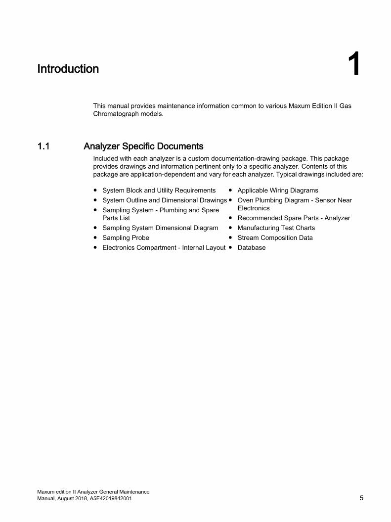
Introduction 1This manual provides maintenance information common to various Maxum Edition II Gas Chromatograph models.
1.1 Analyzer Specific DocumentsIncluded with each analyzer is a custom documentation-drawing package. This package provides drawings and information pertinent only to a specific analyzer. Contents of this package are application-dependent and vary for each analyzer. Typical drawings included are:
● System Block and Utility Requirements● System Outline and Dimensional Drawings● Sampling System - Plumbing and Spare
Parts List● Sampling System Dimensional Diagram● Sampling Probe● Electronics Compartment - Internal Layout
● Applicable Wiring Diagrams● Oven Plumbing Diagram - Sensor Near
Electronics● Recommended Spare Parts - Analyzer● Manufacturing Test Charts● Stream Composition Data● Database
Maxum edition II Analyzer General MaintenanceManual, August 2018, A5E42019842001 5

Introduction1.1 Analyzer Specific Documents
Maxum edition II Analyzer General Maintenance6 Manual, August 2018, A5E42019842001

Safety notes 2Maxum II Analyzers have varying levels of certification for operating in hazardous environments. See the Maxum II Explosion Protection Safety Standards Manual (A5E02220442001), and the Maxum edition II Installation Manual (2000595) for complete information.
The Maxum edition II Process Gas Chromatograph, also called the Maxum II, employs several design and construction features which conform to various international safety standards. These standards are to ensure that the Maxum II and related products can be safely installed and operated in hazardous areas. Each individual detail and component of these safety systems is important to help ensure that the chromatograph does not ignite flammable vapors and gases which may be present in the environment surrounding the analyzer. Therefore, it is important that any personnel that come in contact with the analyzer be familiar with the operation of the safety systems so that they do not compromise safe operation while performing routine maintenance, operation, or other tasks.
DANGER
Explosion risk
Do not install, operate, or service this equipment without reading and understanding all documentation for the equipment and the Safety Data Sheets for all chemicals used in the installation and operation. Failure to follow safe procedures with chemicals commonly used in gas chromatography greatly increases the risk of severe injury or death, and destruction of equipment.
2.1 Approved UseThe Maxum edition II gas chromatograph is primarily used in all branches of the fine chemicals, refining, and hydrocarbon processing industries. It performs chemical composition analysis of gases and liquids that are present in all phases of production. The application flexibility of the Maxum II allows it to analyze a wide variety of samples including feedstock, partially processed streams, final products, and process byproducts including wastes and environmental hazards.
The Maxum II product is intended to be used only in conjunction with other devices and components which have been recommended and approved by Siemens. Appropriate safety standards were used in the development, manufacture, testing, and documentation of the Maxum II. Under normal operation, this product is safe for use providing that all safety and handling guidelines are observed with respect to configuration, assembly, approved use, and maintenance.
This device has been designed with safe isolation between high and low voltage circuits. Low voltages which are connected must also be generated using safe isolation. If any part of the Maxum II is opened, certain parts of the device are accessible which may carry dangerous voltages. Therefore, only suitably qualified personnel may work on this device as indicated in the next section which is titled "Qualified Personnel".
Maxum edition II Analyzer General MaintenanceManual, August 2018, A5E42019842001 7
2.2 Qualified PersonnelOnly suitably qualified personnel may operate or perform maintenance on the Maxum II. For the purposes of safety, qualified personnel are defined as follows:
● Those who have been appropriately trained for the tasks which they are performing (for example, commissioning, maintenance, or operation).
● Those who have been appropriately trained in the operation of the Maxum II process gas chromatograph and are sufficiently acquainted with Maxum II documentation.
● Those who are familiar with the safety concepts of the Maxum II process gas chromatograph and are sufficiently acquainted with Maxum II documentation.
● Those who are authorized to energize, ground, and tag circuits and devices in accordance with established safety practices may perform those tasks for which they are trained.
WARNING
Avoid injury and property damage
Operation or Maintenance of the Maxum II by unqualified personnel or failure to observe the warnings in this manual or on the device may lead to severe personal injury and/or extensive property damage.
WARNING
Do not connect analyzer to the internet.
This equipment must not be connected to the internet except by a secure connection using a network security appliance administered by qualified IT personnel.
Failure to implement robust network security may expose your company to internet hacking attacks that could result in theft or loss of sensitive data, equipment damage, serious injury or death.
For more information see the Maxum II Explosion Protection Safety Standards Manual (A5E02220442001) at Maxum II Explosion Protection Safety Standards Manual (https://support.industry.siemens.com/cs/document/42017542/maxum-edition-ii%3A-explosion-protection-safety-standards?dti=0&pnid=17741).
Safety notes2.2 Qualified Personnel
Maxum edition II Analyzer General Maintenance8 Manual, August 2018, A5E42019842001
System Functions 33.1 Chromatography Overview
Gas Chromatograph TerminologyThe following are some of the terms that are used in this manual.
Application: The supporting hardware and software required to perform the analysis. Supporting hardware consists of hardware channels: detector channel, Solenoid Valve Control Module channel, Electronic Pressure Control channel, Temperature Controller. Streams are defined to applications. If there are 3 or 4 simultaneous streams, they are defined as a single group called a Method. Applications can run only one Method at a time. Two applications can run if there are two cycle clocks in the Maxum II.
Method is the part of the application that contains the parameters for controlling the hardware. Methods control the hardware associated with an Application. The method controls the hardware, including all cycle-clock timed events. Methods are defined to streams. That is, several stream sequences can make up one Method. Methods also control the integration and calculations of the chromatogram. There is one cycle clock per method.
Applet refers to pre-engineered chromatographic segments of common applications, which have been optimized and standardized.
Applet Module refers to a complete assembly including Model 50 valve(s), detector and interconnecting tubing all mounted as a single module. The module includes columns and restrictors
Parallel ChromatographyWith the Maxum II hardware and software, a complex single-train chromatograph analysis can be broken it into multiple simple trains. Each simple train then runs simultaneously – in parallel. This parallel chromatography procedure simplifyies the overall analysis and increases reliability.
Redundant MeasurementsUsing parallel chromatography can reduce calibration requirements by running two identical modules in parallel on the same stream to obtain redundant measurements. As long as the results remain the same within a predefined error limit, the analysis is known to be accurate. Deviations outside the error limit can trigger notification or activate analyzer calibration. Overall, the Maxum II calibration requirements are significantly lower because of the parallel measurement configurations and standard modular applications.
Maxum edition II Analyzer General MaintenanceManual, August 2018, A5E42019842001 9
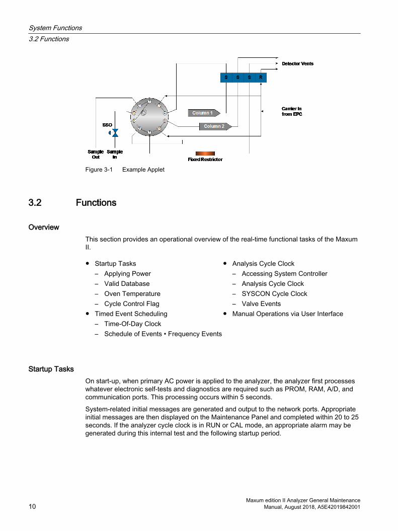
Figure 3-1 Example Applet
3.2 Functions
OverviewThis section provides an operational overview of the real-time functional tasks of the Maxum II.
● Startup Tasks– Applying Power– Valid Database– Oven Temperature– Cycle Control Flag
● Timed Event Scheduling– Time-Of-Day Clock– Schedule of Events • Frequency Events
● Analysis Cycle Clock– Accessing System Controller– Analysis Cycle Clock– SYSCON Cycle Clock– Valve Events
● Manual Operations via User Interface
Startup TasksOn start-up, when primary AC power is applied to the analyzer, the analyzer first processes whatever electronic self-tests and diagnostics are required such as PROM, RAM, A/D, and communication ports. This processing occurs within 5 seconds.
System-related initial messages are generated and output to the network ports. Appropriate initial messages are then displayed on the Maintenance Panel and completed within 20 to 25 seconds. If the analyzer cycle clock is in RUN or CAL mode, an appropriate alarm may be generated during this internal test and the following startup period.
System Functions3.2 Functions
Maxum edition II Analyzer General Maintenance10 Manual, August 2018, A5E42019842001
Self TestAfter the self-test, the following conditions occur:
● Installed hardware is initialized.
● Interrupts are enabled.
● Oven temperatures and carrier pressure default set points are output.
● Analog input system(s), associated with detector inputs, are initialized and begin scanning.
The System Controller (SYSCON) verifies that a valid database is resident, then ouputs the appropriate temperature and carrier set points. If a valid database is not verified, default set points are left in place.
Oven TemperatureThe analyzer monitors the oven temperature to ensure that it has stabilized at the set point before automatically proceeding. Depending on how long primary AC power has been off, this may take from 2 seconds to 45 minutes.
Cycle Control FlagCycle Control Flags can be used to run optional diagnostic cycles to validate analytical hardware including solenoid valves, detectors, or carrier regulators. This option is typically based on a custom application being initiated by a power-fail alarm.
Cycle Ccontrol Flags indicate if any analyzer cycle clocks are to be in RUN mode. If they are not, the analyzer remains in the HOLD mode until operator intervention. If the cycle clock is in RUN mode, based on having been in RUN mode prior to powering down, then RUN mode starts in progress without waiting for intervention.
Program Event SchedulingThe Time of Day (TOD) clock schedules events on a second, minute, hourly, daily or weekly basis. The clock is maintained on the system controller and schedules events from the residing SYSCON database.
The TOD clock has one-second resolution that is maintained and generated by a hardware device that maintains accurate time independent of analyzer power. This allows a power recovery event to determine duration of power down state.
Certain events are scheduled on a frequency basis, which are independent of the TOD or analysis cycle clocks. The frequency clock has a resolution of 1 second, which is used to schedule repetitive events, such as reading DI and AI signals for alarm purposes. Scheduling of frequency events can be set to 5 seconds or greater. They occur regardless of whether the analyzer is in Run or Hold.
DescriptionA schedule event can be for instrument calibration and special calibrations. Special calibrations include daily or shift averages, report logging to a printer or Host computer. When these tasks are scheduled by the TOD clock, they are put into queue. This allows them to be performed at the next appropriate time. Typically, this is after completion of current analysis cycle.
System Functions3.2 Functions
Maxum edition II Analyzer General MaintenanceManual, August 2018, A5E42019842001 11
If a calibration is scheduled, it is put in queue. The calibration then initiates after completion of the current cycle, and when the appropriate time has passed for the calibration blend to flow through the sampling valve. If shift average reports are to be calculated and printed, the report should include all cycles, which started, or sampled, during the specified shift. To have data available for calculation, a wait period may occur for completion of the current sample analysis.
Analysis Cycle ClockThe Analysis Cycle Clock (ACC) is another clock that provides the timebase for all events associated with the actual chromatograph analysis cycle. SYSCON cycle clocks can be configured to provide timed event resolutions of 0.1 second, 0.01 second, 0.01 minute, or 0.001 minute. This is the Sensor Near Electronics software module (SNE) Event Table Scan Rate, which is independent of detector scan rates.
All SYSCON cycle clocks and associated SNE MUST BE of the same second or minute time units. This clock works in conjunction with the Stream Sequence Table and associated sample stream enable and skip flags. This controls sampling order and analysis of process streams connected to the analyzer.
Accessing SYSCONThe clock cycle RUN mode is controlled by the SYSCON upon command from SNE. When a clock cycle is started, the associated SNEs, for that method, initiate a mirror of the cycle clock.
The SNE clock is the true basis of timed events relating to the Gas Chromatograph oven valve timing, detector digitization and peak integration.
SNE Cycle ClockThe SNE cycle clock is used to schedule the following events.
● Analysis valve timing● Detector balances● Temperature set points start and stop for
PTGC
● Cycle Reset ● Pressure set point timing for pressure
programming● Analysis result calculations and reporting
Note
Scheduled solenoid valve events cause Solenoid Valve Control Module (SVCM) hardware to be activated within 5 milliseconds of stated cycle time. Any scheduled pressure set-point adjustments are transferred to the actual Electronic Pressure Control Module (EPCM) hardware within 5 milliseconds.
System Functions3.2 Functions
Maxum edition II Analyzer General Maintenance12 Manual, August 2018, A5E42019842001

Manual OperationsManually controlled functions can be initiated through the color touchscreen. A manually-controlled event can occur asynchronously with any event and control some of the analyzer operations. Controlled items include:
● Activation of solenoid valves● Balancing detectors● Changing a pressure or temperature set
point● Initiating a calculation
● Report logging event● Change the cycle time of an event● Initiate a calibration
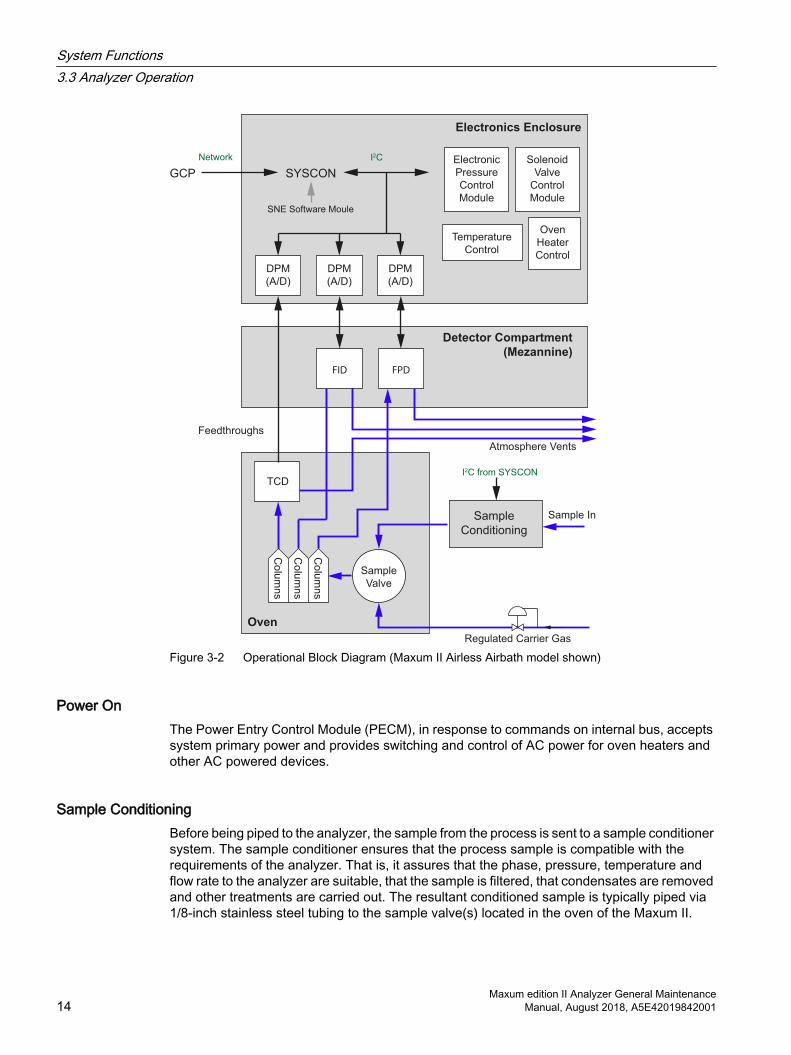
3.3 Analyzer OperationThis section provides an overview of the operation of the Maxum II analyzer. The examples show a Maxum II Airless/Airbath model in order to include many optional features. Most analyzers will have only some of these features; for example, the Modular Oven model has no detector compartment.
The operational block diagram shows how a sample is processed within the analyzer. The SNE functions are performed in software in new systems; older systems still have hardware versions.
System Functions3.3 Analyzer Operation
Maxum edition II Analyzer General MaintenanceManual, August 2018, A5E42019842001 13
FPD
DPM
(A/D)
SYSCON
SNE Software Moule
GCP
I2CNetwork
DPM
(A/D)
Electronic
Pressure
Control
Module
Solenoid
Valve
Control
Module
Temperature
Control
Oven
Heater
Control
Electronics Enclosure
DPM
(A/D)
FID
Detector Compartment
(Mezannine)
Oven
Sample
Conditioning
Atmosphere Vents
Feedthroughs
Sample In
TCD
Co
lum
ns
Sample
Valve
Co
lum
ns
Co
lum
ns
Regulated Carrier Gas
I2C from SYSCON
Figure 3-2 Operational Block Diagram (Maxum II Airless Airbath model shown)
Power OnThe Power Entry Control Module (PECM), in response to commands on internal bus, accepts system primary power and provides switching and control of AC power for oven heaters and other AC powered devices.
Sample ConditioningBefore being piped to the analyzer, the sample from the process is sent to a sample conditioner system. The sample conditioner ensures that the process sample is compatible with the requirements of the analyzer. That is, it assures that the phase, pressure, temperature and flow rate to the analyzer are suitable, that the sample is filtered, that condensates are removed and other treatments are carried out. The resultant conditioned sample is typically piped via 1/8-inch stainless steel tubing to the sample valve(s) located in the oven of the Maxum II.
System Functions3.3 Analyzer Operation
Maxum edition II Analyzer General Maintenance14 Manual, August 2018, A5E42019842001
Sample ValveThe type of sample valve used in a Maxum II is application dependent. Five primary types of sample valves are available.
● The first is the 10-port Model 50 valve that is designed for vapor sample only.
● The second is the Model 11 valve for vapor or liquid samples.
● Third is the Model 20 valve for liquid high-pressure samples.
● The fourth type is the set of Valco valves that are designed for high temperatures and very low sample volumes.
● The fifth is the independently-heated Siemens Liquid Injection Valve.
The sample valve(s) and any column valves are controlled by a Solenoid Valve Control Module located in the Maxum II’s electronics compartment. There can be up to three SVCMs installed in an electronics compartment (EC).
Solenoid Valve Control ModuleThe Solenoid Valve Control Module (SVCM) provides pneumatic on/off control for both sampling and oven systems functions. The SVCM manifolds are connected as a group of four 4-way and four 3-way solenoids. The (SVCM) receives commands from the I2C bus. Solenoid commands are received from the SNE software module. Solenoid relay status is read back to the SNE software module to indicate whether a selected solenoid is to be deactivated or activated. Timing is controlled by SNE software module timing. There is no timebase in the SVCM.
Commands from I2C bus control the deactivation or activation of solenoid valves. If fault or warning conditions have occurred, pressure control and SVCM status information is returned to the SYSCON database.
ColumnsSamples are injected by the sample valves into the chromatograph columns where the samples are separated into individual components. Many different types of columns may be used including 1/16-inch micro-packed, 1/8-inch packed and fused silica or metal capillaries. The columns used are dependent on the requirements of the application.
Column ValvesIn most applications, there are multiple columns in use that are typically switched by column valves located in between them. These column valves are not shown in the illustration, but like the sample valves described above they are also controlled by the Solenoid Valve Control Module and SNE software module.
System Functions3.3 Analyzer Operation
Maxum edition II Analyzer General MaintenanceManual, August 2018, A5E42019842001 15
Electronic Pressure ControlThe carrier gas pressure that is used to push the sample through the columns is controlled by an Electronic Pressure Control Module (EPCM) or in some applications by mechanical regulators. The EPCM is mounted on manifolds located on the EC right-side wall. The EPCM pneumatics are digitally controlled by the Sensor Near Electronics (SNE) software module. Up to four EPCMs can be mounted in an EC. Each EPCM contains two channels, and each channel can use a different gas at a different pressure. EPCMs are also used to control the fuels for some of the detector modules. Each Electronic Pressure Control Module (EPCM) communicates the actual pressure back to the SNE software module. Information may then be displayed on the Maintenance Panel. Depending on model and application, up to 3 or 4 EPCMs may be installed
Oven HeatersFor the columns and detectors to work correctly, they must usually be operated at elevated temperatures. The Maxum II uses electrical heater(s) to elevate the temperature. These heaters (not shown in block diagram) are connected to relays in the electronics compartment and, like the valves and the Electronic Pressure Control Modules, are controlled by the SNE software module.
DetectorThe sample eluted from the columns is transported to the associated detector that senses the presence of the sample and converts it to an electrical signal. Depending upon the application, the Maxum II can include up to three detector modules. Each detector module can have multiple detector sensor elements. Several detector module types are available including Thermistor, Filament, Flame Ionization, Flame Photometric, and Pulsed Discharge. The resulting electrical signal from the detector is then connected to the Detector Personality Module (DPM) located in the EC.
Sensor Near Electronics (SNE) Software ModuleThe detector signal(s) is routed to the Detector Personality Module (DPM). The DPM (unique for each detector type) amplifies the analog signal and converts it to a digital signal. The digital signal output from the DPM is processed by the SNE software module. The DPM is interfaced to installed peripherals connected to the I2C bus through a set of digital and analog I/O signal commands. All accessible I/O's are uniquely addressable through the module type, enclosure ID, SNE, location ID and module channel number.
In earlier analyzers, the SNE control and processing functions were performed by a separate processor board, called the SNE controller (SNECON) mounted in the DPM cage assembly and connected to the SYSCON by an Ethernet cable.
System Controller (SYSCON)The System Controller (SYSCON) resides in a pullout drop-down assembly located in the EC and controls all external communications and internal communication. The SYSCON houses the primary processor, plug-in I/O boards (for external signal control), communication interfaces, and an interface to the maintenance panel display. All internal communication between modules and SYSCON is via the internal I2C signal bus.
System Functions3.3 Analyzer Operation
Maxum edition II Analyzer General Maintenance16 Manual, August 2018, A5E42019842001

The original SYSCON consists of a single controller board. The newest version of SYSCON, called SYSCON2, is a base SIB (SYSCON Interface Board) with an attached CAC3 (Communication and Control board). The SYSCON combines all data results and performs additional high level data processing and calculations. The SYSCON connects to a color touchscreen display, strip chart recorder, other analyzers, printers, the Advance Communication System (ACS), or other connected networks.
The SYSCON is the analyzer control system in addition to containing the application database. The application database also contains analytical hardware database definitions that are used to perform the following functions:
● Obtain desired sampling measurements● I/O and SNE schedule of timing events● Sequence of sampling streams
● Calculations of reported values● Formatting of results and location and
outputting results● How to report or correct error conditions
3.4 Data Communication
Internal CommunicationAn I2C Internal Bus provides communication between the SYSCON, SVCM, EPC, PECM and to the I/O bus. External communication is through an Ethernet link. The interface for each type of module is described in the Component Descriptions and Maintenance Procedures section.
Software SNE
DPM 3
Software SNE
DPM 2
I2C I2C I2C
Sampling
System
I2C
CAC3
CAN
RS485
RS232
Analyzers
GCP
Ethernet
Ethernet
Switch
(optional)
I/O
Boards
I2C
I2CEPCs
SVCMsEthernet
I2C I2C
GCP
Color
Touch
Display
SYSCON
(SIB3)
PECM
Controller
Board
Software SNE
DPM 1
Figure 3-3 Data Communication Paths
System Functions3.4 Data Communication
Maxum edition II Analyzer General MaintenanceManual, August 2018, A5E42019842001 17
Module AddressingThe Maxum II modules located in the electronic compartment have their own physical address and communicate via the I2C Internal Bus, shown in the diagram below. Address information is contained in the SYSCON database and identifies modules by their location. Each DPM is associated with a software SNE module that appears in the list as a separate device.
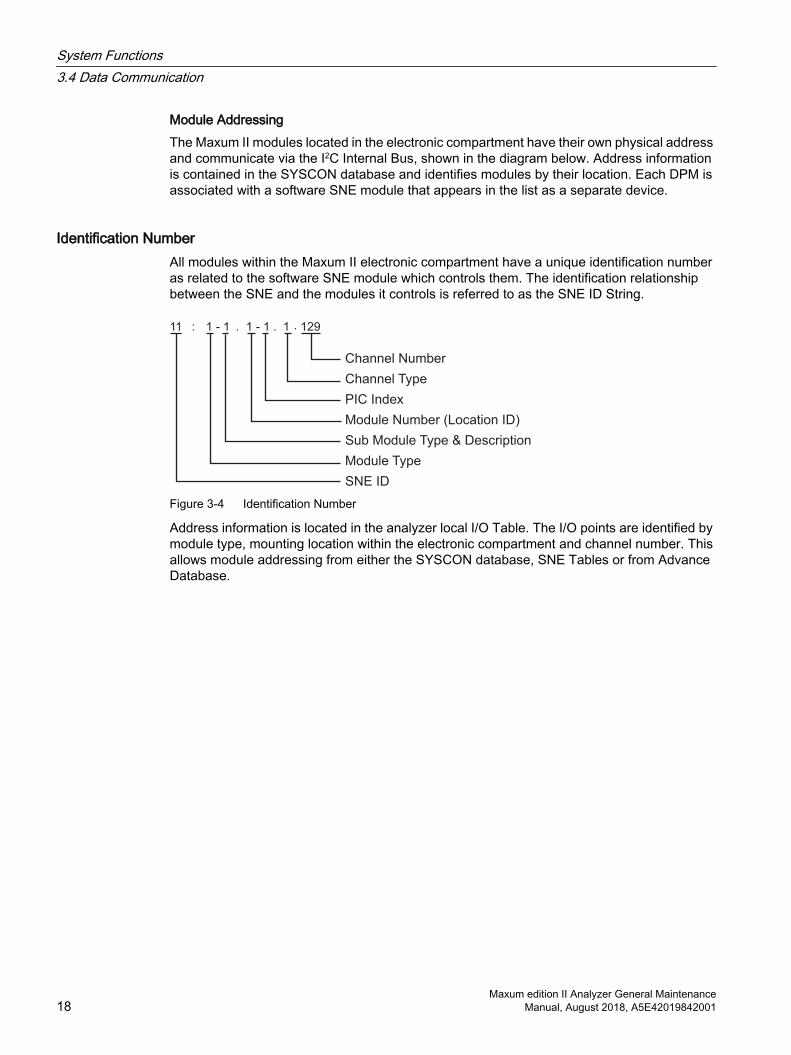
Identification NumberAll modules within the Maxum II electronic compartment have a unique identification number as related to the software SNE module which controls them. The identification relationship between the SNE and the modules it controls is referred to as the SNE ID String.
. 129.1 - 1.: 11 - 111
SNE ID
Module Type
Channel Type
Channel Number
PIC Index
Module Number (Location ID)
Sub Module Type & Description
Figure 3-4 Identification Number
Address information is located in the analyzer local I/O Table. The I/O points are identified by module type, mounting location within the electronic compartment and channel number. This allows module addressing from either the SYSCON database, SNE Tables or from Advance Database.
System Functions3.4 Data Communication
Maxum edition II Analyzer General Maintenance18 Manual, August 2018, A5E42019842001
General Maintenance and Troubleshooting 44.1 Analyzer Status Indicators
4.1.1 Operator Controls
Color Touchscreen
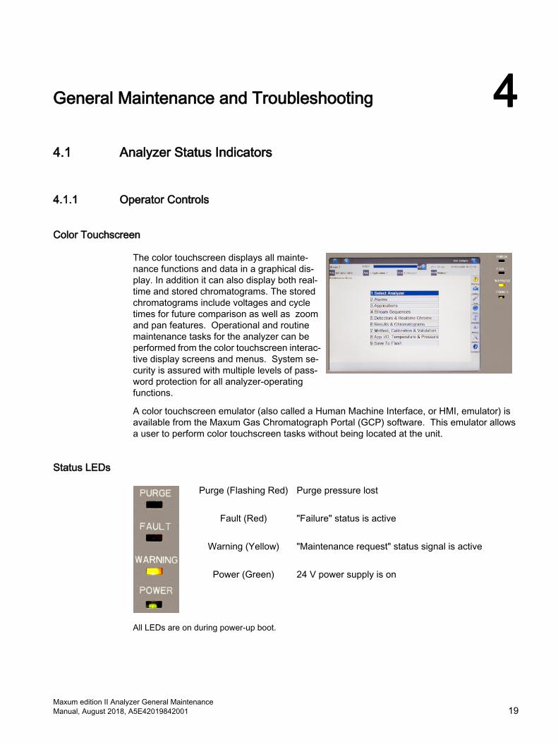
The color touchscreen displays all mainte‐nance functions and data in a graphical dis‐play. In addition it can also display both real-time and stored chromatograms. The stored chromatograms include voltages and cycle times for future comparison as well as zoom and pan features. Operational and routine maintenance tasks for the analyzer can be performed from the color touchscreen interac‐tive display screens and menus. System se‐curity is assured with multiple levels of pass‐word protection for all analyzer-operating functions.
A color touchscreen emulator (also called a Human Machine Interface, or HMI, emulator) is available from the Maxum Gas Chromatograph Portal (GCP) software. This emulator allows a user to perform color touchscreen tasks without being located at the unit.
Status LEDs
Purge (Flashing Red)
Purge pressure lost
Fault (Red)
"Failure" status is active
Warning (Yellow)
"Maintenance request" status signal is active
Power (Green) 24 V power supply is on
All LEDs are on during power-up boot.
Maxum edition II Analyzer General MaintenanceManual, August 2018, A5E42019842001 19
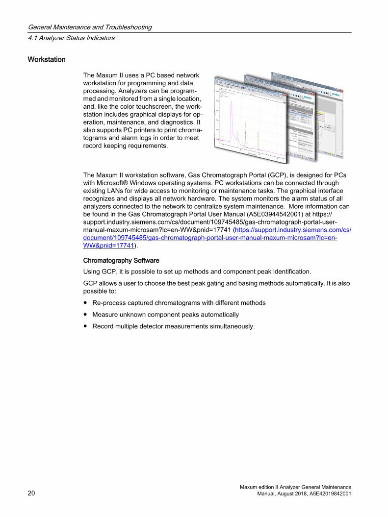
Workstation
The Maxum II uses a PC based network workstation for programming and data processing. Analyzers can be program‐med and monitored from a single location, and, like the color touchscreen, the work‐station includes graphical displays for op‐eration, maintenance, and diagnostics. It also supports PC printers to print chroma‐tograms and alarm logs in order to meet record keeping requirements.
The Maxum II workstation software, Gas Chromatograph Portal (GCP), is designed for PCs with Microsoft® Windows operating systems. PC workstations can be connected through existing LANs for wide access to monitoring or maintenance tasks. The graphical interface recognizes and displays all network hardware. The system monitors the alarm status of all analyzers connected to the network to centralize system maintenance. More information can be found in the Gas Chromatograph Portal User Manual (A5E03944542001) at https://support.industry.siemens.com/cs/document/109745485/gas-chromatograph-portal-user-manual-maxum-microsam?lc=en-WW&pnid=17741 (https://support.industry.siemens.com/cs/document/109745485/gas-chromatograph-portal-user-manual-maxum-microsam?lc=en-WW&pnid=17741).
Chromatography SoftwareUsing GCP, it is possible to set up methods and component peak identification.
GCP allows a user to choose the best peak gating and basing methods automatically. It is also possible to:
● Re-process captured chromatograms with different methods
● Measure unknown component peaks automatically
● Record multiple detector measurements simultaneously.
General Maintenance and Troubleshooting4.1 Analyzer Status Indicators
Maxum edition II Analyzer General Maintenance20 Manual, August 2018, A5E42019842001

4.1.2 LED States Inside the Electronics Cabinet
4.1.2.1 Base3DPM Status Indicator LEDs
Normal
Fault
Warning
Power Active
Heater 2
Temp Limit
Overtemp
Flameout
Ignite
Alternate Range
Power Active
Heater 1
Temp Limit
Overtemp
Figure 4-1 Base3DPM Status LEDs
General Maintenance and Troubleshooting4.1 Analyzer Status Indicators
Maxum edition II Analyzer General MaintenanceManual, August 2018, A5E42019842001 21
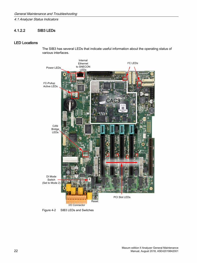
4.1.2.2 SIB3 LEDs
LED LocationsThe SIB3 has several LEDs that indicate useful information about the operating status of various interfaces.
I2C-Pullup
Active LEDs
3210
PCI Slot LEDs
Reset
I/O Connector
DI Mode
Switch
(Set to Mode 2)
CAN
Bridge
LEDs
Power LEDs
Internal
Ethernet
to SNECON
LEDs
CAC3
I2C LEDs
Figure 4-2 SIB3 LEDs and Switches
General Maintenance and Troubleshooting4.1 Analyzer Status Indicators
Maxum edition II Analyzer General Maintenance22 Manual, August 2018, A5E42019842001
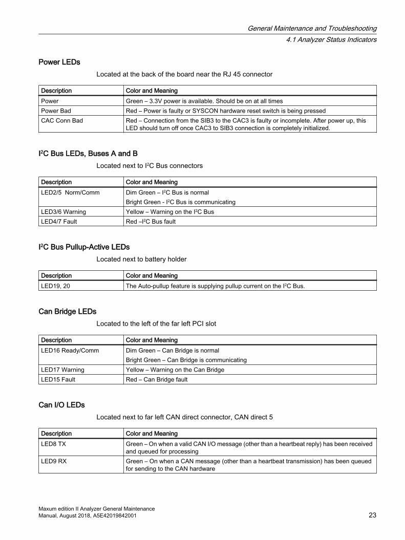
Power LEDsLocated at the back of the board near the RJ 45 connector
Description Color and MeaningPower Green – 3.3V power is available. Should be on at all timesPower Bad Red – Power is faulty or SYSCON hardware reset switch is being pressedCAC Conn Bad Red – Connection from the SIB3 to the CAC3 is faulty or incomplete. After power up, this
LED should turn off once CAC3 to SIB3 connection is completely initialized.
I2C Bus LEDs, Buses A and BLocated next to I2C Bus connectors
Description Color and MeaningLED2/5 Norm/Comm Dim Green – I2C Bus is normal
Bright Green - I2C Bus is communicatingLED3/6 Warning Yellow – Warning on the I2C BusLED4/7 Fault Red –I2C Bus fault
I2C Bus Pullup-Active LEDsLocated next to battery holder
Description Color and MeaningLED19, 20 The Auto-pullup feature is supplying pullup current on the I2C Bus.
Can Bridge LEDsLocated to the left of the far left PCI slot
Description Color and MeaningLED16 Ready/Comm Dim Green – Can Bridge is normal
Bright Green – Can Bridge is communicatingLED17 Warning Yellow – Warning on the Can BridgeLED15 Fault Red – Can Bridge fault
Can I/O LEDsLocated next to far left CAN direct connector, CAN direct 5
Description Color and MeaningLED8 TX Green – On when a valid CAN I/O message (other than a heartbeat reply) has been received
and queued for processingLED9 RX Green – On when a CAN message (other than a heartbeat transmission) has been queued
for sending to the CAN hardware
General Maintenance and Troubleshooting4.1 Analyzer Status Indicators
Maxum edition II Analyzer General MaintenanceManual, August 2018, A5E42019842001 23

Description Color and MeaningLED10 Heartbeat Green – Flashes once for each heartbeat message transmitted. This LED will flash once
every 1.5 seconds for each active CAN cardLED11 Fault Red – On when an error state is detected on the CAN bus hardware
PCI Slot LEDsLocated between PCI slots
Description Color and MeaningLED14 Slot 0 Fault Red – Overcurrent or thermal shutdown on PCI slot 0LED13 Slot 1 Fault Red – Overcurrent or thermal shutdown on PCI slot 1LED18 Slot 2 Fault Red – Overcurrent or thermal shutdown on PCI slot 2LED12 Slot 3 Fault Red – Overcurrent or thermal shutdown on PCI slot 3
Internal Ethernet LEDsLocated next to and on SIB3 RJ-45 connector
Description Color and MeaningGreen LED on RJ-45 Green – LED is green when link is in full duplex modeYellow LED on RJ-45 Yellow – LED is on when link is active. Will flash off for transmit or receive activity.LED1 Speed Green –
On – Speed is 100 Mb/sec (or auto-negotiating)Off – Speed is 10 Mb/sec (or disconnected)
General Maintenance and Troubleshooting4.1 Analyzer Status Indicators
Maxum edition II Analyzer General Maintenance24 Manual, August 2018, A5E42019842001
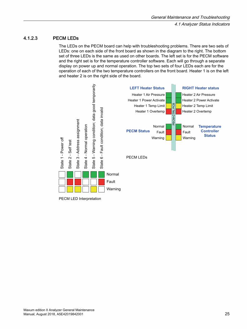
4.1.2.3 PECM LEDsThe LEDs on the PECM board can help with troubleshooting problems. There are two sets of LEDs: one on each side of the front board as shown in the diagram to the right. The bottom set of three LEDs is the same as used on other boards. The left set is for the PECM software and the right set is for the temperature controller software. Each will go through a separate display on power up and normal operation. The top two sets of four LEDs each are for the operation of each of the two temperature controllers on the front board. Heater 1 is on the left and heater 2 is on the right side of the board.
Sta
te 1
- P
ow
er
off
Sta
te 2
- S
elf te
st
Sta
te 3
- A
dd
ress a
ssig
nm
en
t
Sta
te 4
- N
orm
al o
pe
ratio
n
Sta
te 5
- W
arn
ing
co
nd
itio
n; d
ata
go
od
te
mp
ora
rily
Sta
te 6
- F
au
lt c
on
ditio
n; d
ata
in
va
lid
Normal
Fault
Warning
PECM LED Interpretation
PE
CM
-CT
RL P
CB
LEFT Heater Status RIGHT Heater status
Heater 1 Air Pressure
Heater 1 Power Activate
Heater 1 Temp Limit
Heater 1 Overtemp
Heater 2 Air Pressure
Heater 2 Power Activate
Heater 2 Temp Limit
Heater 2 Overtemp
Normal
Fault
Warning
Normal
Fault
Warning
PECM Status
Temperature
Controller
Status
PECM LEDs
General Maintenance and Troubleshooting4.1 Analyzer Status Indicators
Maxum edition II Analyzer General MaintenanceManual, August 2018, A5E42019842001 25
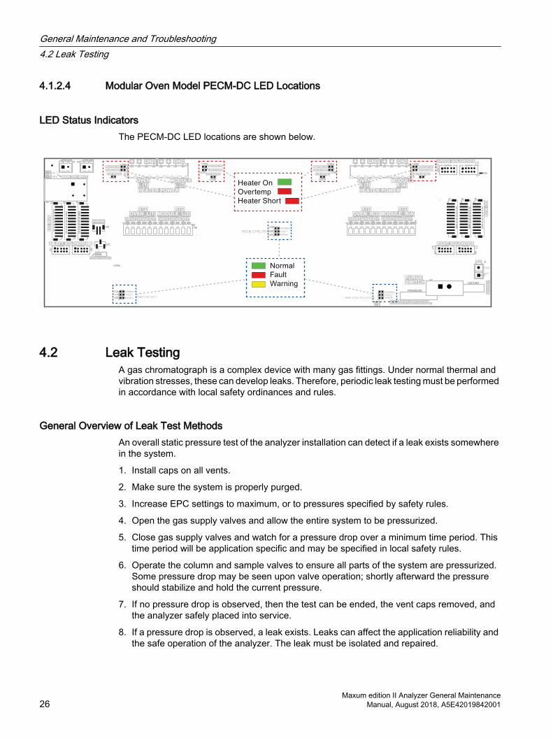
4.1.2.4 Modular Oven Model PECM-DC LED Locations
LED Status IndicatorsThe PECM-DC LED locations are shown below.
4.2 Leak TestingA gas chromatograph is a complex device with many gas fittings. Under normal thermal and vibration stresses, these can develop leaks. Therefore, periodic leak testing must be performed in accordance with local safety ordinances and rules.
General Overview of Leak Test MethodsAn overall static pressure test of the analyzer installation can detect if a leak exists somewhere in the system.
1. Install caps on all vents.
2. Make sure the system is properly purged.
3. Increase EPC settings to maximum, or to pressures specified by safety rules.
4. Open the gas supply valves and allow the entire system to be pressurized.
5. Close gas supply valves and watch for a pressure drop over a minimum time period. This time period will be application specific and may be specified in local safety rules.
6. Operate the column and sample valves to ensure all parts of the system are pressurized. Some pressure drop may be seen upon valve operation; shortly afterward the pressure should stabilize and hold the current pressure.
7. If no pressure drop is observed, then the test can be ended, the vent caps removed, and the analyzer safely placed into service.
8. If a pressure drop is observed, a leak exists. Leaks can affect the application reliability and the safe operation of the analyzer. The leak must be isolated and repaired.
General Maintenance and Troubleshooting4.2 Leak Testing
Maxum edition II Analyzer General Maintenance26 Manual, August 2018, A5E42019842001
4.3 General Analyzer Shutdown Procedure
Back Up the DatabaseIf a current database has not been saved, first save a database to a remote device to provide a potential method of reloading if a CAC3 has been replaced or an earlier database needs to be restored to the analyzer. Generally, a database reload will not be needed, though in some cases this may be required.
1. Put the Maxum II in Hold and wait for the cycle to complete. This will provide the quickest restart of the application when power is restored.
2. After the cycle has completed and the analyzer is in Hold:
– Turn off carrier gas, valve gas, instrument air, and sample flows.
– Remove power from the unit.
WARNING
Voltage dangerous to life exists. Failure to follow appropriate safety procedures may result in severe injury or death.
Before beginning to work inside the electronics compartment, the power must be externally removed from the GC. AC power comes directly into the electronics enclosure, so power must be removed and secured/tagged to prevent inadvertent application while work is being performed.
4.4 General Analyzer Startup ProcedureThe startup procedure described in this section explains the principle steps necessary to power the Maxum II in a manner that does not compromise the safety systems of the analyzer.
Note
The specific application and the facility in which this equipment is installed will impose additional requirements for startup and shutdown.
This section does not explain the startup procedures required that relate to software functions or the analytical application of the analyzer. Please see other documentation and manuals for information and startup steps that relate to these other aspects of startup.
General Maintenance and Troubleshooting4.4 General Analyzer Startup Procedure
Maxum edition II Analyzer General MaintenanceManual, August 2018, A5E42019842001 27
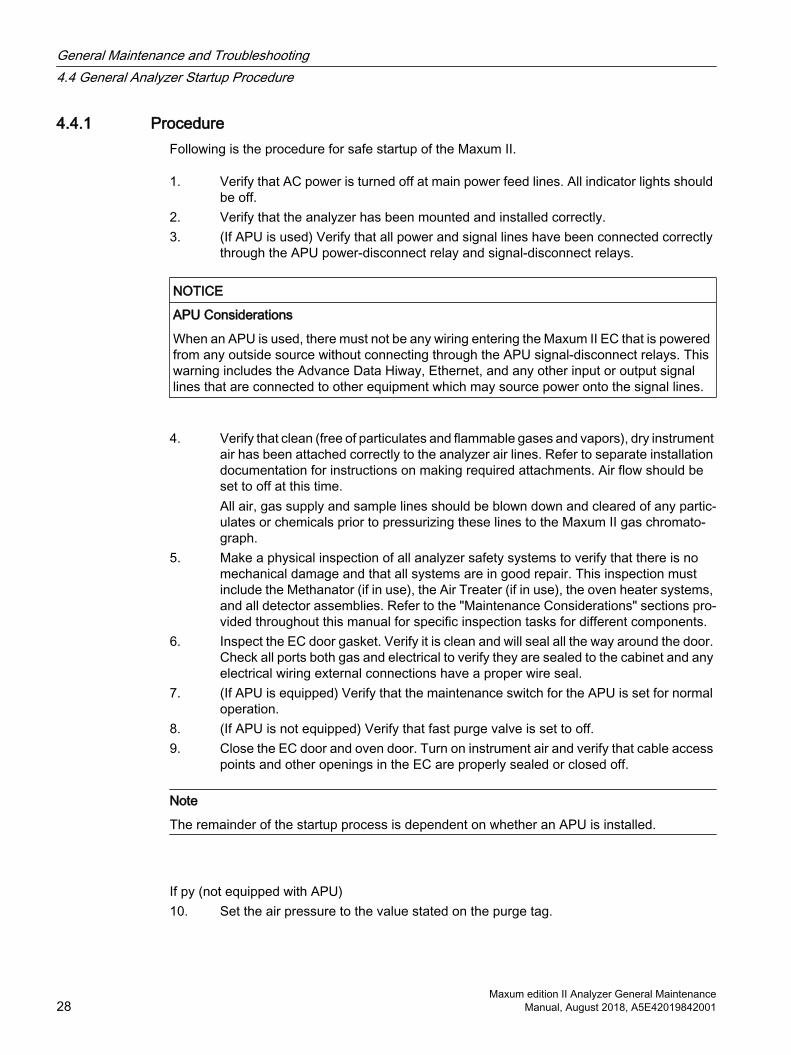
4.4.1 ProcedureFollowing is the procedure for safe startup of the Maxum II.
1. Verify that AC power is turned off at main power feed lines. All indicator lights should be off.
2. Verify that the analyzer has been mounted and installed correctly.3. (If APU is used) Verify that all power and signal lines have been connected correctly
through the APU power-disconnect relay and signal-disconnect relays.
NOTICE
APU Considerations
When an APU is used, there must not be any wiring entering the Maxum II EC that is powered from any outside source without connecting through the APU signal-disconnect relays. This warning includes the Advance Data Hiway, Ethernet, and any other input or output signal lines that are connected to other equipment which may source power onto the signal lines.
4. Verify that clean (free of particulates and flammable gases and vapors), dry instrument air has been attached correctly to the analyzer air lines. Refer to separate installation documentation for instructions on making required attachments. Air flow should be set to off at this time.All air, gas supply and sample lines should be blown down and cleared of any partic‐ulates or chemicals prior to pressurizing these lines to the Maxum II gas chromato‐graph.
5. Make a physical inspection of all analyzer safety systems to verify that there is no mechanical damage and that all systems are in good repair. This inspection must include the Methanator (if in use), the Air Treater (if in use), the oven heater systems, and all detector assemblies. Refer to the "Maintenance Considerations" sections pro‐vided throughout this manual for specific inspection tasks for different components.
6. Inspect the EC door gasket. Verify it is clean and will seal all the way around the door. Check all ports both gas and electrical to verify they are sealed to the cabinet and any electrical wiring external connections have a proper wire seal.
7. (If APU is equipped) Verify that the maintenance switch for the APU is set for normal operation.
8. (If APU is not equipped) Verify that fast purge valve is set to off.9. Close the EC door and oven door. Turn on instrument air and verify that cable access
points and other openings in the EC are properly sealed or closed off.
Note
The remainder of the startup process is dependent on whether an APU is installed.
If py (not equipped with APU)10. Set the air pressure to the value stated on the purge tag.
General Maintenance and Troubleshooting4.4 General Analyzer Startup Procedure
Maxum edition II Analyzer General Maintenance28 Manual, August 2018, A5E42019842001
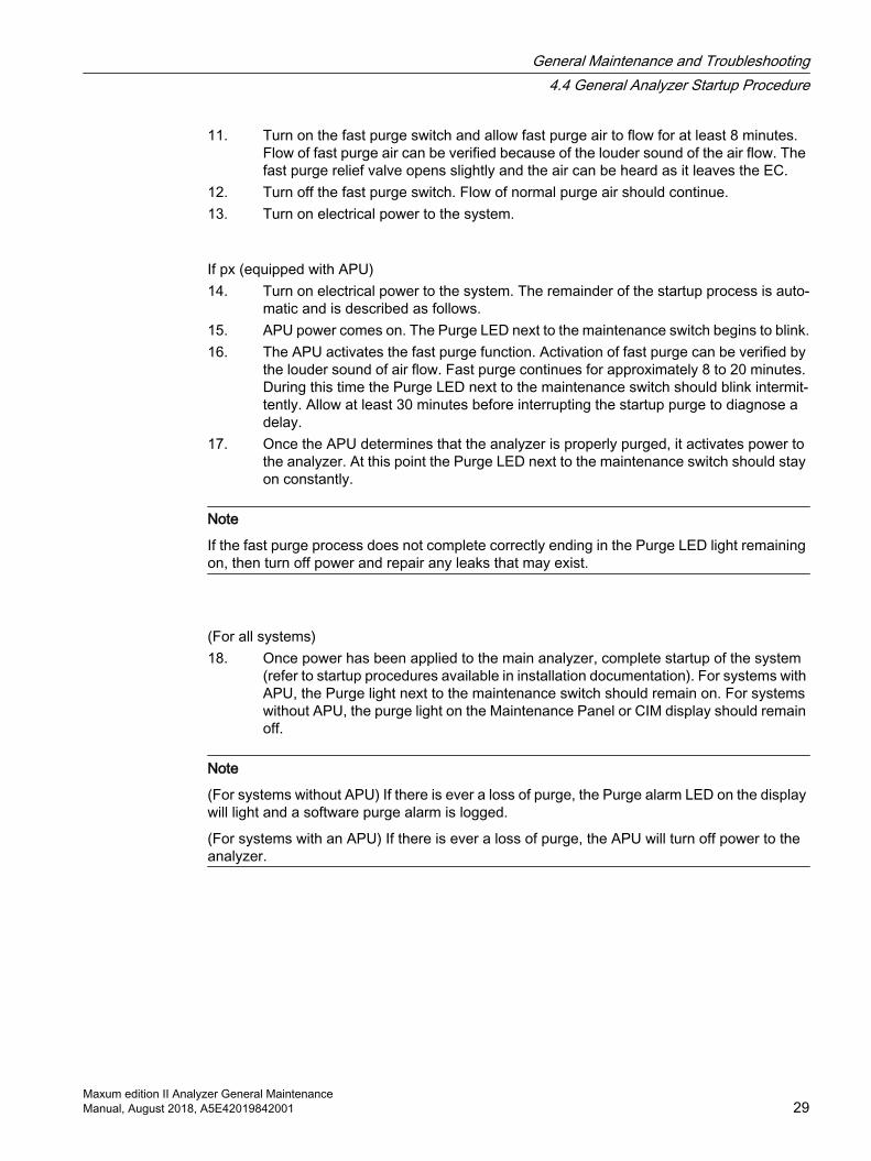
11. Turn on the fast purge switch and allow fast purge air to flow for at least 8 minutes. Flow of fast purge air can be verified because of the louder sound of the air flow. The fast purge relief valve opens slightly and the air can be heard as it leaves the EC.
12. Turn off the fast purge switch. Flow of normal purge air should continue.13. Turn on electrical power to the system.
If px (equipped with APU)14. Turn on electrical power to the system. The remainder of the startup process is auto‐
matic and is described as follows.15. APU power comes on. The Purge LED next to the maintenance switch begins to blink.16. The APU activates the fast purge function. Activation of fast purge can be verified by
the louder sound of air flow. Fast purge continues for approximately 8 to 20 minutes. During this time the Purge LED next to the maintenance switch should blink intermit‐tently. Allow at least 30 minutes before interrupting the startup purge to diagnose a delay.
17. Once the APU determines that the analyzer is properly purged, it activates power to the analyzer. At this point the Purge LED next to the maintenance switch should stay on constantly.
Note
If the fast purge process does not complete correctly ending in the Purge LED light remaining on, then turn off power and repair any leaks that may exist.
(For all systems)18. Once power has been applied to the main analyzer, complete startup of the system
(refer to startup procedures available in installation documentation). For systems with APU, the Purge light next to the maintenance switch should remain on. For systems without APU, the purge light on the Maintenance Panel or CIM display should remain off.
Note
(For systems without APU) If there is ever a loss of purge, the Purge alarm LED on the display will light and a software purge alarm is logged.
(For systems with an APU) If there is ever a loss of purge, the APU will turn off power to the analyzer.
General Maintenance and Troubleshooting4.4 General Analyzer Startup Procedure
Maxum edition II Analyzer General MaintenanceManual, August 2018, A5E42019842001 29
4.5 Accessing the Bootloader
Accessing the Bootloader to Set the Network AddressThis procedure is needed when a CAC3 is replaced, when the memory backup battery is removed, or when the CAC3 is removed from a CIM or SIB3. In this procedure, the term "SYSCON" can mean either a SYSCON assembly in a Maxum Airless/Airbath model or a CIM in a MAxum Modular Oven model analyzer. To prepare, disconnect the analyzer from the network by unlugging the Ethernet cable.
From the color touchscreen in the door of the analyzer, use this set of steps to set the IP addresses. This allows the GCP software to communicate with the device so that a database may be loaded.
1. Push the reset button through the opening on the SYSCON cage. This provides access to the bootloader.
2. Press the Home key when the message “To enter the bootloader menu, press the Home key now…” appears.
3. Press the 5 key to select the “Configuration” menu.
4. Press the 4 key to select “Choose Device Mode”.
5. Press the 2 key to select “Standalone SysCon”.
6. The SYSCON reboots into standalone mode.
7. Press the Home key to re-enter the boot loader
8. Press the 5 key to select the “Configuration” menu again.
9. Press the 2 key to select “Primary Ethernet IP Configuration”.
10.The question “Do you want to change this configuration?” appears: Press the 9 key to select “Yes”.
11.Press the 0 key to disable DHCP.
12.Press the 9 key to change the IP address.
13.Enter the desired IP address. Press the “Home” key to return to the menu.
14.Press the 9 key to change the subnet mask.
15.Enter the correct subnet mask. Press the “Home” key to return to the menu.
16.Press the 9 key to change the Default Gateway address.
17.Enter the Default Gateway address. Press the “Home” key to return to the menu.
18.Press the 0 key to select “No” to the question “Change the DNS?”
19.Press any key to continue.
20.Press the Back key to return to the bootloader menu.
21.Press the 9 key to reset the device.
The external Ethernet cable may now be reconnected to the network, and the analyzer should be visible in the GCP Network list.
General Maintenance and Troubleshooting4.5 Accessing the Bootloader
Maxum edition II Analyzer General Maintenance30 Manual, August 2018, A5E42019842001

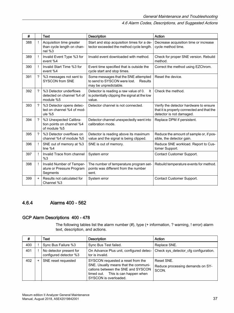
4.6 Alarm Codes, Descriptions, and Suggested Actions
4.6.1 Alarms 301 - 324
GCP Alarm Descriptions 301 - 324The following tables list the alarm number (#), type (+ information, ? warning, ! error) alarm text, description, and actions.
# Text Description Action301 ? External Message: send
failure %3A message was received by the device from itself; or source of message can't be identified; or Gateway is too busy or com‐munication was disrupted between the GC and the message handler.
Reset Gateway or SYSCON.
302 ? External Message: server lost
System Error Contact Customer Support.
303 + External Message: Rec'd invalid communication from unit %3
Message was received from Advance DataHiway unit that had previously broadcast with no slots or slot is out of range.
Reset Advance DataHiway unit.
304 + External Message: Orphan message received from %3
An Advance DataHiway external PANDSP message was received with no matching PANKEY; or an ATTACH was received with no matching RATCH; or an internal timeout was generated for non-existent message.
Ignore or reset SYSCON.
305 ? External Message: Invalid Message Length for %3
Advance DataHiway Results, print, HAE, or Service Panel messages received from GC that have no length.
Check database set up for these mes‐sages.
306 + External Message: Send in‐valid communication to unit %3
Message from GC is directed to an Ad‐vance DataHiway unit that has no slots, an invalid range of slots, or no UID has ever been received.
Check Advance DataHiway unit.
307 ? External Message: Dupli‐cate anlz_id %3 detected ; setting to zero
An Advance DataHiway ZIP message was received from another Advance Da‐taHiway unit, or another GC has broad‐cast with the same analyzer num‐ber.Check other units on network.
Check other units on network.
308 ? External Message: Dupli‐cate UNIT %3 detected; setting loop/unit to zero
An Advance DataHiway SLEEP mes‐sage has been received. Another Ad‐vance DataHiway unit has broadcast with the same loop/unit.
Check other units on Advance DataHi‐way and correct loop/unit of GC.
309 ? External Message: RUD:Unit does not re‐spond; loop/unit %3
Occurs when Advance DataHiway loop/unit does not respond to a RUD message - originates from I/O, Host, or Printer ta‐ble in GC.
Remove extraneous references to non-existent units. Check Advance Data‐Hiway connection.
General Maintenance and Troubleshooting4.6 Alarm Codes, Descriptions, and Suggested Actions
Maxum edition II Analyzer General MaintenanceManual, August 2018, A5E42019842001 31
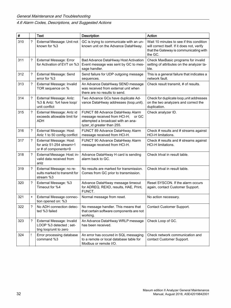
# Text Description Action310 ? External Message: Unit not
known for %3GC is trying to communicate with an un‐known unit on the Advance DataHiway.
Wait 10 minutes to see if this condition will correct itself. If it does not, verify that the Gateway is communicating with the GC.
311 ? External Message: Error for Activation of EVT on %3
Bad Advance DataHiway Host Activation Event message was sent by GC to mes‐sage handler.
Check MaxBasic programs for invalid setting of attributes on the analyzer ta‐ble.
312 ? External Message: Send error for %3
Send failure for UDP outgoing message sequences.
This is a general failure that indicates a network fault.
313 ? External Message: Invalid TOR sequence on %
An Advance DataHiway SEND message was received from external unit when there are no results to send.
Check result transmit, # of results.
314 ? External Message: Anlz: %3 & Anlz: %4 have loop/unit conflict
Two Advance GCs have duplicate Ad‐vance DataHiway addresses (loop,unit).
Check for duplicate loop,unit addresses on the two analyzers and correct the duplication.
315 ? External Message: Anlz id exceeds allowable limit for ADH
FUNCT 88 Advance DataHiway Alarm message received from HCI-H; or GC attempted a broadcast with an ana‐lyzer_id greater than 255.
Check analyzer ID.
316 ? External Message: Host: Anlz 1 to 50 config conflict
FUNCT 89 Advance DataHiway Alarm message received from HCI-H.
Check # results and # streams against HCI-H limitations.
317 ? External Message: Host: for anlz 51-254 stream>1 or # of components>9
FUNCT 90 Advance DataHiway Alarm message received from HCI-H.
Check # results and # streams against HCI-H limitations.
318 ? External Message: Host: in‐valid data received from anlz
Advance DataHiway H card is sending alarm back to GC.
Check trtval in result table.
319 ? External Message: no re‐sults marked to transmit for stream %3
No results are marked for transmission. Comes from GC prior to transmission.
Check trtval in result table.
320 ? External Message: %3 Timeout for %4
Advance DataHiway message timeout for ADREQ, REXD, results, HAE, Print, FUNCT.
Reset SYSCON. If the alarm occurs again, contact Customer Support.
321 + External Message connec‐tion opened on: %3
Normal message from reset. No action necessary.
322 ? No ADH connection detec‐ted %3 failed
No message handler. This means that that certain software components are not working.
Contact Customer Support.
323 ? External Message: Invalid LOOP %3 detected ; set‐ting loop/unit to zero
An Advance DataHiway WRLP message has been received.
Check Loop of GC.
324 ! Error processing database command %3
An error has occured in SQL messaging to a remote or local database table for Modbus or remote I/O.
Check network communication and contact Customer Support.
General Maintenance and Troubleshooting4.6 Alarm Codes, Descriptions, and Suggested Actions
Maxum edition II Analyzer General Maintenance32 Manual, August 2018, A5E42019842001

4.6.2 Alarms 330 through 359 SNE Communication
GCP Alarm Descriptions 330 - 359The following tables list the alarm number (#), type (+ information, ? warning, ! error) alarm text, description, and actions.
# Text Description Action331 ! Run Method: No SNE
found or bad status on mod‐ule: %3
The connection between the GC and the SNE is invalid.
Check cable between the SNE and SY‐SCON. Check the LEDs on the SNE to see if it is running.
332 ! Run Method: No module found for detr: %3
The SNE has not reported the detector, pressure controller, or temperature con‐troller.
Check hardware connections to SNE. The GC can contain references to inva‐lid hardware channels. Check the pressure, temperature, and detector channels defined in the appli‐cation for correct assignments.
333 ! Run Method: No Detr found or bad status for meth‐od.channel: %3
Realtime chromatogram attempt on inva‐lid detector, or bad status on detector.
Check hrdwr_id, module for app_detec‐tor. The GC can contain references to invalid hardware channels. Check the detector channels defined in the application for correct assignments.
334 ! Run Method: No Channel found for method: %3
No channels are present or can't find de‐tector for channel.
Check app_detector, EZChrom method for proper hardware channel assign‐ments.
335 + SNE connection opened on %3
System error Contact Customer Support.
336 ! SNE connection closed on %3 error: %4
SNE connection closed due to timeout or error.
If IP address specified is not a 192.168.144.# network address, check for appropriate grounding of system.Otherwise check SNE for appropriate connections and software versions.
337 ! SNE connection replaced on %3
System error Contact Customer Support.
338 ? SNE %3 Method %4 Can‐not Store Chrom
Results received from SNE for unknown stream.
Check stream table. It is possible to de‐lete streams during the run of a cycle. If that is done, then this alarm may oc‐cur.
339 ? SNE %3 Method %4 Appli‐cation %5 not found
Can't find application or method to match SNE results. This indicates that messag‐es between the SNE and SYSCON are corrupted.
Reset SNE to sychronize messages. It is possible to delete applications during the run of a cycle. If that is attempted, then this alarm may occur.
340 ! SNE %3 Method %4 Load - Invalid Method
SNE has sent a status message that the method is invalid. No other information is available.
Download method from EZChrom again.
341 ! SNE %3 Method %4 Inac‐tive
SNE sent message that method is inac‐tive. No other information is available.
Restart the application.
342 ! SNE %3 Method %4 Load - Max Method exceeded
SNE sent message that maximum meth‐ods has been exceeded.
Reduce number of methods, reset SY‐SCON.
General Maintenance and Troubleshooting4.6 Alarm Codes, Descriptions, and Suggested Actions
Maxum edition II Analyzer General MaintenanceManual, August 2018, A5E42019842001 33

# Text Description Action343 ! SNE %3 Method %4 Load
- Invalid ModeInvalid run/hold sent to SNE. Reset SYSCON or try placing applica‐
tion in run.344 ! SNE %3 Method %4 status
- unknown error %5Unknown error from SNE method status. Reset SNE/SYSCON.
345 ! Stream Valve does not ex‐ist
Can't find appdo or sys_do for DO set in cycle_events. Digital Output on cy‐cle_event may not be valid.
Check DO on application I/O tables to see if the DO exists for this application and has a normal status.
346 ! SNE %3 Write IO %4 does not exist %5
IO write was sent to SNE, where I/O does not exist.
Reset SNE/SYSCON. Check the sys_hardware table for nor‐mal I/O status. If any I/O is not normal, investigate the cause.
347 ! SNE %3 Read IO %4 does not exist
IO read was sent to SNE where the I/O does not exist.
Reset SNE/SYSCONCheck the sys_hardware table for nor‐mal I/O status. If any I/O is not normal, investigate the cause.
348 ? SNE %3 RT chrom %4 does not exist
Realtime chromatogram request to non-existent SNE.
Reset SNE/SYSCONCheck the sys_hardware table for nor‐mal I/O status. If any I/O is not normal, investigate the cause.
349 ? SNE %3 Method %4 - Write attempted on active meth‐od
Ignore: Alarm was removed from Ver‐sions 4.3 and later.
350 ! SNE Module I/O error 0x %3 on %4
An operation attempted on an attached SNE module failed.
Report the error number and the mod‐ule to Customer Support.
351 ! SNE pSOS error 0x %3 on %4
System Software Failure. Report the error number and the mod‐ule to Customer Support.
352 ! SNE pSOS Driver error 0x %3 on %4
Driver Software Failure. Report the error number and the mod‐ule to Customer Support.
353 ! SNE AAI Driver error 0x %3 on %4
AAI custom driver failure. Report the error number and the mod‐ule to Customer Support.
354 ? SNE TFTP load Error on %3 : %4
TFTP load failure during download of SNE software.
Verify that TFTP server is runningVerify correct IP addressVerify correct file locationRetry TFTP load
355 ? SNE FLASH Driver Error on %3 : %4
Flash Memory Failure. If persistent, replace SNE.
356 ! SNE %3 Stream/Method %4 / %5 does not exist
Results received from SNE: Can't locate stream/method. Deleting streams and methods or downloading methods while a cycle is running can cause this error.
Check sequence. Place application in hold and then run again.
357 ! SNE Method %3 - Invalid message argument
This indicates that the SNE has an obso‐lete software version or the messages between the SNE and SYSCON have been corrupted.
Check the SNE and SYSCON software versions with the upgrade tool. Reset the SYSCON and SNE.
General Maintenance and Troubleshooting4.6 Alarm Codes, Descriptions, and Suggested Actions
Maxum edition II Analyzer General Maintenance34 Manual, August 2018, A5E42019842001

# Text Description Action358 ! SNE Invalid I/O Write from
SNE on %4 , command %5This should only occur if the SNE has an old software version or the messages be‐tween the SNE and SYSCON have been corrupted.
Check the SNE and SYSCON software versions with the upgrade tool. Reset the SYSCON and SNE.
359 ! SNE I/O not found on I/O Write from SNE: %4
This should only occur if the SNE has an old software version or the messages be‐tween the SNE and SYSCON have been corrupted.
Check the SNE and SYSCON software versions with the upgrade tool. Reset the SYSCON and SNE.
4.6.3 Alarms 360 - 399
GCP Alarm Descriptions 360 - 399The following tables list the alarm number (#), type (+ information, ? warning, ! error) alarm text, description, and actions.
# Text Description Action360 ! %!3 %4 General SNE Fault. Contact Customer Support.361 ? %3 %4 General SNE warning. Contact Customer Support.362 + %3 %4 General SNE note. Contact Customer Support.363 ! Invalid function request %3
from SYSCONThis indicates that the SNE has an obso‐lete software version, or that the messag‐es between the SNE and SYSCON have been corrupted.
Check the SNE and SYSCON software versions with the upgrade tool. Reset the SYSCON and SNE.
364 ? No real-time buffer exists for detector %3 on DPM %4
Detector data is being collected for a de‐tector that wasn't properly enabled.
If received during a load sequence, it is an artifact of the shutdown sequence. Otherwise, record occurrence and DPM information and report to Custom‐er Support.
365 ! Incomplete Analysis on channel %3
EZChrom analysis was not completed on channel.
Modify integration events in method.Send method to Customer Support.
366 ! Data Corruption Error Major Data corruption on SNE Reset SNEReport error to Customer Support.
367 ! System Error %3 in File %4 line %5
System Software Failure. Record sequence of events leading to occurrence and report error, along with the complete contents of the alarm mes‐sage, to Customer Support.
368 ! Unable to find %3 number %4
Hardware specified in method is not in analyzer.
Verify that the method is correct.
369 ! Unsupported channel type %3
Hardware channel operation requested for an invalid channel type.
Inspect for current version of SNE soft‐ware. May require a reload or rebuild of corrupted SYSCON database.
370 ? No channel %3 on DPM %4 for realtime display
Realtime display requested for a detector channel that doesn't exist. Indicates da‐tabase corruption.
Restore an older version of the data‐base.
General Maintenance and Troubleshooting4.6 Alarm Codes, Descriptions, and Suggested Actions
Maxum edition II Analyzer General MaintenanceManual, August 2018, A5E42019842001 35

# Text Description Action371 ! Invalid channel acquisition
overlap on %3Two channels referencing the same hardware detector are scheduled to ac‐quire at the same time.
If multiple application detector channels are assigned to the same hardware de‐tector, do not allow their times to over‐lap.
372 ! Scheduling error %3 scan‐ning %4 # %5 channel %6
Unable to schedule all event and polling routines. May indicate a memory or hard‐ware failure.
If method schedules many events as well as all 18 detectors, try removing some of the events or deleting some of the detectors, then resetting the SNE.
373 ! Module I/O error %3 on %4 # %5 channel %6
Error between module and channel. Indi‐cates obsolete anayler.
Consider upgrading analyzer.
374 ! Internal communication er‐ror %3
Software modules inside SNE are failing to communicate. Usually happens with out of memory condition resulting from SYSCON timeout.
Reduce processing requirements on SYSCON.
375 ! End of cycle missed; stop‐ping cycle
The message that coordinates the end of a method around the SNE tasks was lost.
Reset SNE.Reduce the complexity of the SNE set‐up. Replace SNE.
376 + Adjusting cycle clock mas‐ter
Obsolete software version. Contact Customer Support.
377 ! Error %3 scheduling cycle clock master adjustment
Resource not found for scheduling ad‐justment of event clock. SNE may be overloaded.
Reduce complexity of tasks for SNE.Reset SNE to prevent event clock overflow.
378 + %3 samples adjusted on chrom from channel %4
An excessive number of samples re‐quired adjustment on chromatogram. Oc‐curs in conjunction with DPM alarms.
Replace affected DPM.
379 ! Error %3 preparing analy‐sis for channel %4
EZChrom processing error. Check integration events; modify events that may cause problems.
380 ! Error %3 finding chrom peaks for channel %4
EZChrom processing error. Check integration events and peak ta‐ble; modify events that may cause prob‐lems.
381 ! Error %3 generating re‐sults for channel %4
EZChrom processing error. Example er‐ror: Setting the threshold value too low, causing many peaks to be detected in the noise of the chromatogram.
Check method for problems that could affect results.
382 ! EZChrom server failed er‐ror %3 on channel %4
Resource problem on SNE. Reduce SNE workload.Replace SNE.
383 ? Software Watchdog Time‐out
SNE is running out of processing capaci‐ty.
Reduce SNE workload. Replace SNE.
384 ! Method Modification Failed An attempt to modify a running method failed, most likely due to invalid data.
Verify that modification was valid.
385 ? Event occurred before modification request
Before a modification of a running meth‐od was completed, the event occurred.
Contact Customer Support.
386 ! Invalid Cycle Length %3 A cycle length larger than the maximum size was specified in a method. Usually caused by a corrupt method. Maximum cycle length is approximately 2 days.
Verify correct values in method.
387 ! Invalid Sample Rate %3 on channel %4
Invalid sample rate value chosen for channel in method.
Verify the methods and use only a sup‐ported detector sample rate.
General Maintenance and Troubleshooting4.6 Alarm Codes, Descriptions, and Suggested Actions
Maxum edition II Analyzer General Maintenance36 Manual, August 2018, A5E42019842001
# Text Description Action388 ! Acquisition time greater
than cycle length on chan‐nel %3
Start and stop acquisition times for a de‐tector exceeded the method cycle length.
Decrease acquisition time or increase cycle method time.
389 ! Invalid Event Type %3 for event %4
Invalid event downloaded with method. Check for proper SNE version. Rebuild method.
390 ! Invalid Start Time %3 for event %4
Event time specified that is outside the cycle start and stop times.
Correct the method using EZChrom.
391 ? %3 messages not sent to SYSCON from SNE
Some messages that the SNE attempted to send to SYSCON were lost. Results may be unpredictable.
Reset the device.
392 ? %3 Detector underflows detected on channel %4 of module %5
Detector is reading a raw value of 0. It is potentially clipping the signal at the low value.
Check the method.
393 ? %3 Detector opens detec‐ted on channel %4 of mod‐ule %5
Detector channel is not connected. Verify the detector hardware to ensure that it is properly connected and that the detector is not damaged.
394 ? %3 Unexpected Calibra‐tion points on channel %4 of module %5
Detector channel unexpectedly went into calibration mode.
Replace DPM if persistent.
395 ? %3 Detector overflows on channel %4 of module %5
Detector is reading above its maximum value and the signal is being clipped.
Reduce the amount of sample or, if pos‐sible, the detector gain.
396 ! SNE out of memory at %3 line %4
SNE is out of memory. Reduce SNE workload. Report to Cus‐tomer Support.
397 ! Invalid Trace from channel %3
System error Contact Customer Support.
398 ! Invalid Number of Temper‐ature or Pressure Program Segments
The number of temperature program set‐points was different from the number sent.
Rebuild temperature events for method.
399 + Results not calculated for Channel %3
System error Contact Customer Support.
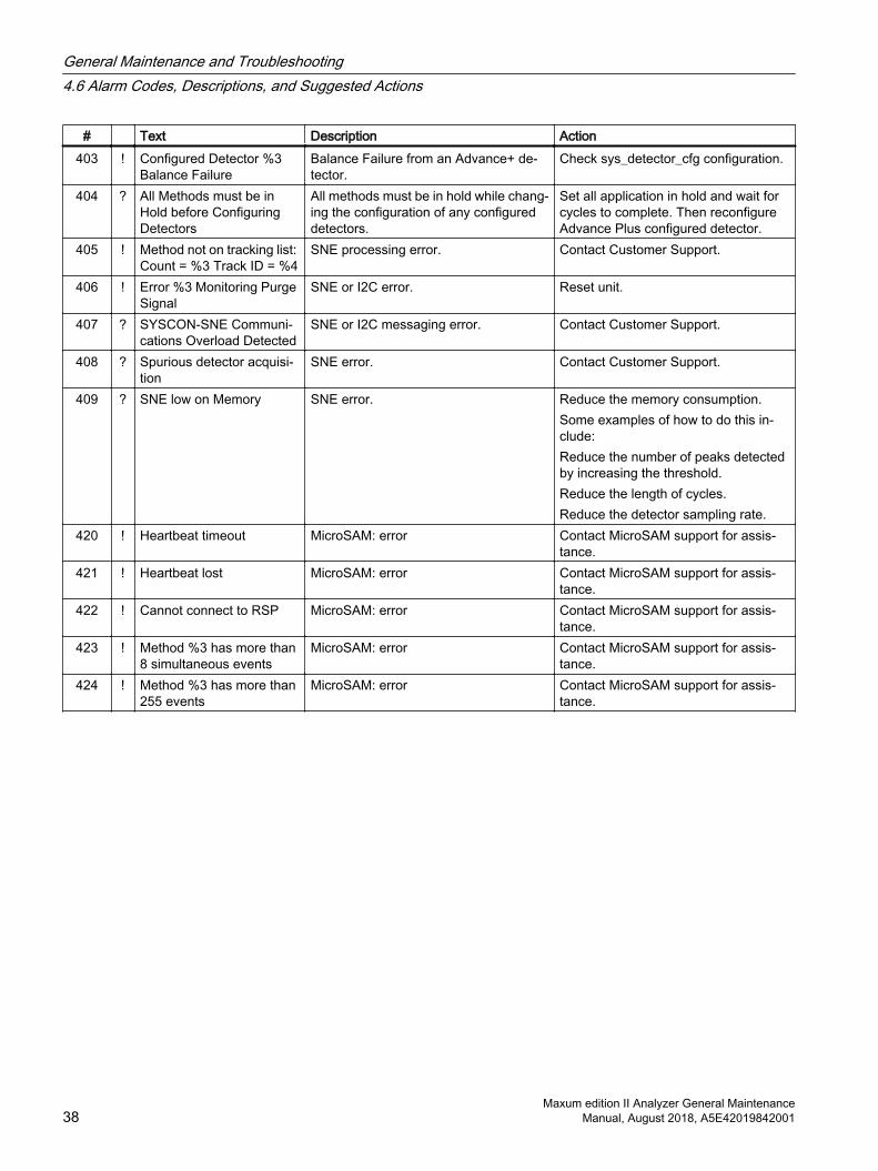
4.6.4 Alarms 400 - 562
GCP Alarm Descriptions 400 - 478The following tables list the alarm number (#), type (+ information, ? warning, ! error) alarm text, description, and actions.
# Text Description Action400 ! Sync Bus Failure %3 Sync Bus Test failed. Replace SNE.401 ! No detector present for
configured detector %3On Advance Plus unit, configured detec‐tor is invalid.
Check sys_detector_cfg configuration.
402 + SNE reset requested SYSCON requested a reset from the SNE. Usually means that the communi‐cations between the SNE and SYSCON timed out. This is can happen when SYSCON is overloaded.
Reset SNE.Reduce processing demands on SY‐SCON.
General Maintenance and Troubleshooting4.6 Alarm Codes, Descriptions, and Suggested Actions
Maxum edition II Analyzer General MaintenanceManual, August 2018, A5E42019842001 37
# Text Description Action403 ! Configured Detector %3
Balance FailureBalance Failure from an Advance+ de‐tector.
Check sys_detector_cfg configuration.
404 ? All Methods must be in Hold before Configuring Detectors
All methods must be in hold while chang‐ing the configuration of any configured detectors.
Set all application in hold and wait for cycles to complete. Then reconfigure Advance Plus configured detector.
405 ! Method not on tracking list: Count = %3 Track ID = %4
SNE processing error. Contact Customer Support.
406 ! Error %3 Monitoring Purge Signal
SNE or I2C error. Reset unit.
407 ? SYSCON-SNE Communi‐cations Overload Detected
SNE or I2C messaging error. Contact Customer Support.
408 ? Spurious detector acquisi‐tion
SNE error. Contact Customer Support.
409 ? SNE low on Memory SNE error. Reduce the memory consumption. Some examples of how to do this in‐clude:Reduce the number of peaks detected by increasing the threshold.Reduce the length of cycles.Reduce the detector sampling rate.
420 ! Heartbeat timeout MicroSAM: error Contact MicroSAM support for assis‐tance.
421 ! Heartbeat lost MicroSAM: error Contact MicroSAM support for assis‐tance.
422 ! Cannot connect to RSP MicroSAM: error Contact MicroSAM support for assis‐tance.
423 ! Method %3 has more than 8 simultaneous events
MicroSAM: error Contact MicroSAM support for assis‐tance.
424 ! Method %3 has more than 255 events
MicroSAM: error Contact MicroSAM support for assis‐tance.
General Maintenance and Troubleshooting4.6 Alarm Codes, Descriptions, and Suggested Actions
Maxum edition II Analyzer General Maintenance38 Manual, August 2018, A5E42019842001
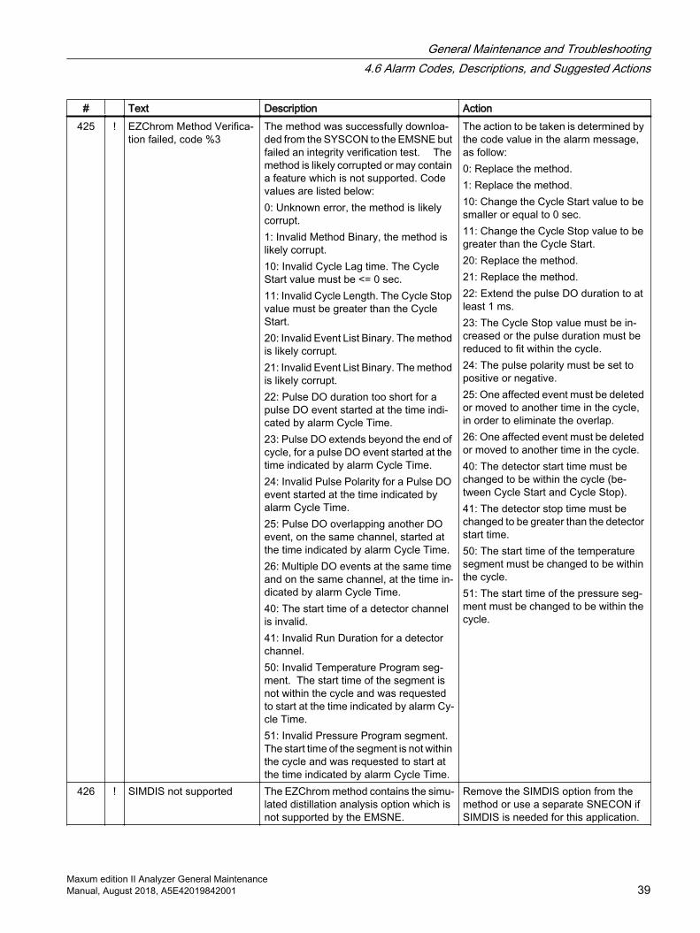
# Text Description Action425 ! EZChrom Method Verifica‐
tion failed, code %3The method was successfully downloa‐ded from the SYSCON to the EMSNE but failed an integrity verification test. The method is likely corrupted or may contain a feature which is not supported. Code values are listed below:0: Unknown error, the method is likely corrupt.1: Invalid Method Binary, the method is likely corrupt.10: Invalid Cycle Lag time. The Cycle Start value must be <= 0 sec.11: Invalid Cycle Length. The Cycle Stop value must be greater than the Cycle Start.20: Invalid Event List Binary. The method is likely corrupt.21: Invalid Event List Binary. The method is likely corrupt.22: Pulse DO duration too short for a pulse DO event started at the time indi‐cated by alarm Cycle Time.23: Pulse DO extends beyond the end of cycle, for a pulse DO event started at the time indicated by alarm Cycle Time.24: Invalid Pulse Polarity for a Pulse DO event started at the time indicated by alarm Cycle Time.25: Pulse DO overlapping another DO event, on the same channel, started at the time indicated by alarm Cycle Time.26: Multiple DO events at the same time and on the same channel, at the time in‐dicated by alarm Cycle Time.40: The start time of a detector channel is invalid.41: Invalid Run Duration for a detector channel. 50: Invalid Temperature Program seg‐ment. The start time of the segment is not within the cycle and was requested to start at the time indicated by alarm Cy‐cle Time.51: Invalid Pressure Program segment. The start time of the segment is not within the cycle and was requested to start at the time indicated by alarm Cycle Time.
The action to be taken is determined by the code value in the alarm message, as follow:0: Replace the method.1: Replace the method.10: Change the Cycle Start value to be smaller or equal to 0 sec.11: Change the Cycle Stop value to be greater than the Cycle Start.20: Replace the method.21: Replace the method.22: Extend the pulse DO duration to at least 1 ms.23: The Cycle Stop value must be in‐creased or the pulse duration must be reduced to fit within the cycle.24: The pulse polarity must be set to positive or negative.25: One affected event must be deleted or moved to another time in the cycle, in order to eliminate the overlap.26: One affected event must be deleted or moved to another time in the cycle.40: The detector start time must be changed to be within the cycle (be‐tween Cycle Start and Cycle Stop).41: The detector stop time must be changed to be greater than the detector start time.50: The start time of the temperature segment must be changed to be within the cycle.51: The start time of the pressure seg‐ment must be changed to be within the cycle.
426 ! SIMDIS not supported The EZChrom method contains the simu‐lated distillation analysis option which is not supported by the EMSNE.
Remove the SIMDIS option from the method or use a separate SNECON if SIMDIS is needed for this application.
General Maintenance and Troubleshooting4.6 Alarm Codes, Descriptions, and Suggested Actions
Maxum edition II Analyzer General MaintenanceManual, August 2018, A5E42019842001 39
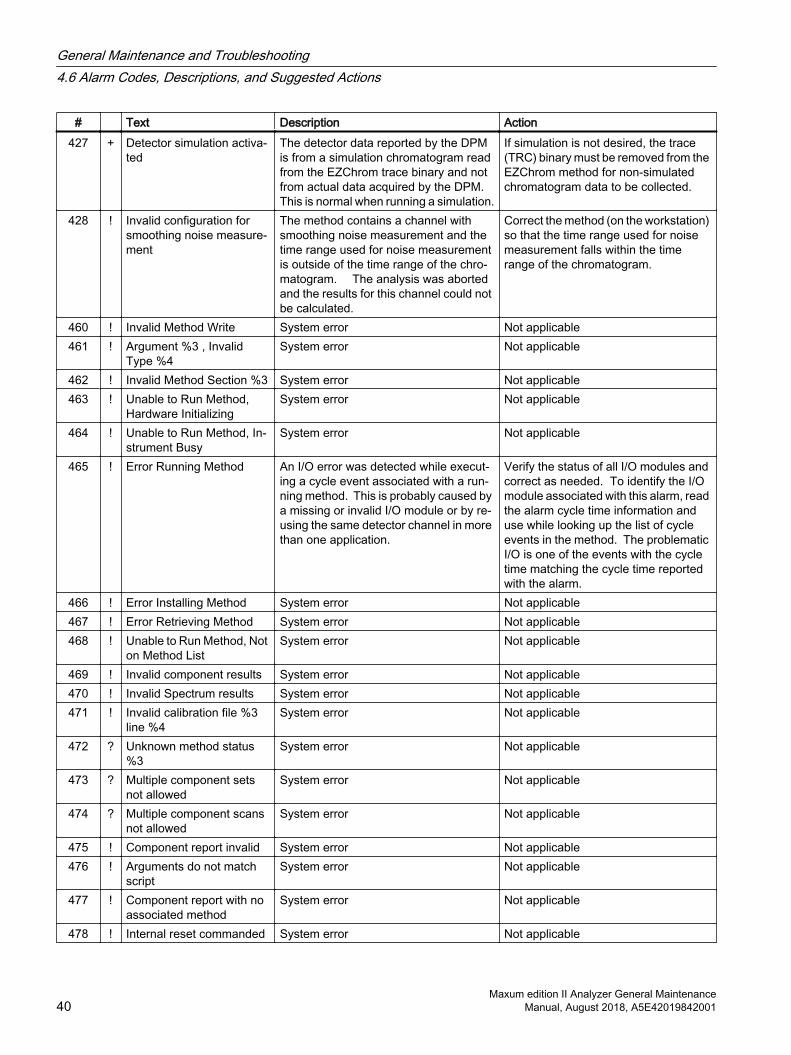
# Text Description Action427 + Detector simulation activa‐
tedThe detector data reported by the DPM is from a simulation chromatogram read from the EZChrom trace binary and not from actual data acquired by the DPM. This is normal when running a simulation.
If simulation is not desired, the trace (TRC) binary must be removed from the EZChrom method for non-simulated chromatogram data to be collected.
428 ! Invalid configuration for smoothing noise measure‐ment
The method contains a channel with smoothing noise measurement and the time range used for noise measurement is outside of the time range of the chro‐matogram. The analysis was aborted and the results for this channel could not be calculated.
Correct the method (on the workstation) so that the time range used for noise measurement falls within the time range of the chromatogram.
460 ! Invalid Method Write System error Not applicable461 ! Argument %3 , Invalid
Type %4System error Not applicable
462 ! Invalid Method Section %3 System error Not applicable463 ! Unable to Run Method,
Hardware InitializingSystem error Not applicable
464 ! Unable to Run Method, In‐strument Busy
System error Not applicable
465 ! Error Running Method An I/O error was detected while execut‐ing a cycle event associated with a run‐ning method. This is probably caused by a missing or invalid I/O module or by re‐using the same detector channel in more than one application.
Verify the status of all I/O modules and correct as needed. To identify the I/O module associated with this alarm, read the alarm cycle time information and use while looking up the list of cycle events in the method. The problematic I/O is one of the events with the cycle time matching the cycle time reported with the alarm.
466 ! Error Installing Method System error Not applicable467 ! Error Retrieving Method System error Not applicable468 ! Unable to Run Method, Not
on Method ListSystem error Not applicable
469 ! Invalid component results System error Not applicable470 ! Invalid Spectrum results System error Not applicable471 ! Invalid calibration file %3
line %4System error Not applicable
472 ? Unknown method status %3
System error Not applicable
473 ? Multiple component sets not allowed
System error Not applicable
474 ? Multiple component scans not allowed
System error Not applicable
475 ! Component report invalid System error Not applicable476 ! Arguments do not match
scriptSystem error Not applicable
477 ! Component report with no associated method
System error Not applicable
478 ! Internal reset commanded System error Not applicable
General Maintenance and Troubleshooting4.6 Alarm Codes, Descriptions, and Suggested Actions
Maxum edition II Analyzer General Maintenance40 Manual, August 2018, A5E42019842001
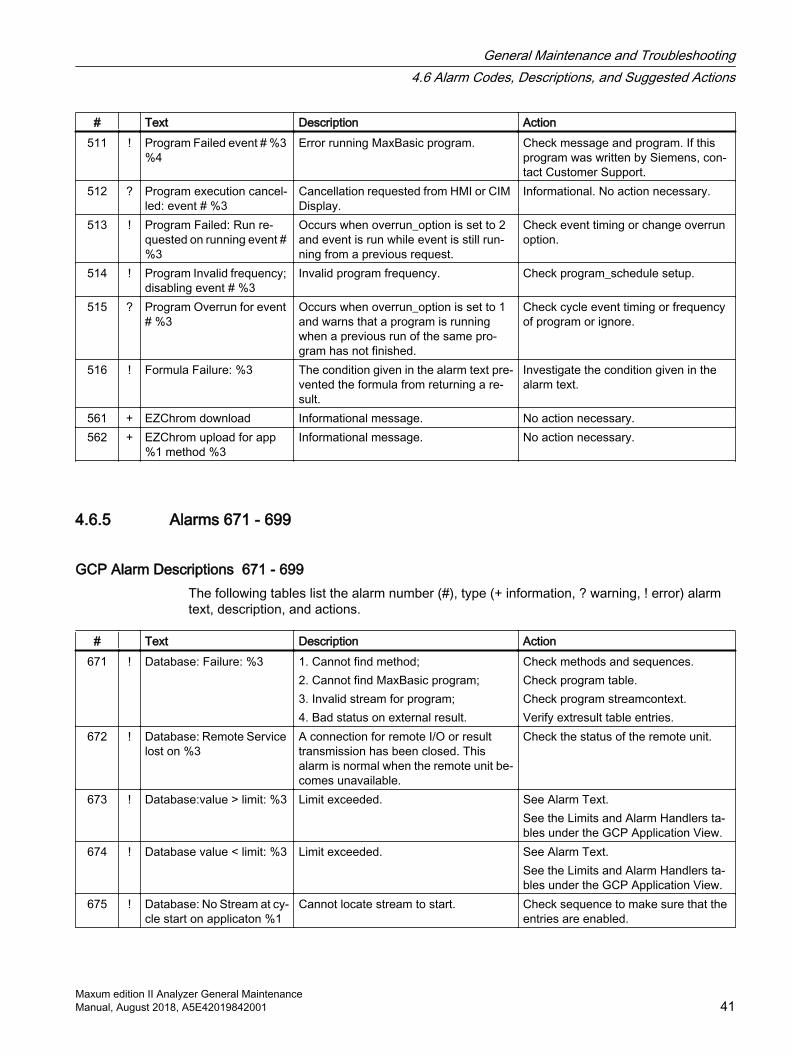
# Text Description Action511 ! Program Failed event # %3
%4Error running MaxBasic program. Check message and program. If this
program was written by Siemens, con‐tact Customer Support.
512 ? Program execution cancel‐led: event # %3
Cancellation requested from HMI or CIM Display.
Informational. No action necessary.
513 ! Program Failed: Run re‐quested on running event # %3
Occurs when overrun_option is set to 2 and event is run while event is still run‐ning from a previous request.
Check event timing or change overrun option.
514 ! Program Invalid frequency; disabling event # %3
Invalid program frequency. Check program_schedule setup.
515 ? Program Overrun for event # %3
Occurs when overrun_option is set to 1 and warns that a program is running when a previous run of the same pro‐gram has not finished.
Check cycle event timing or frequency of program or ignore.
516 ! Formula Failure: %3 The condition given in the alarm text pre‐vented the formula from returning a re‐sult.
Investigate the condition given in the alarm text.
561 + EZChrom download Informational message. No action necessary.562 + EZChrom upload for app
%1 method %3Informational message. No action necessary.
4.6.5 Alarms 671 - 699
GCP Alarm Descriptions 671 - 699The following tables list the alarm number (#), type (+ information, ? warning, ! error) alarm text, description, and actions.
# Text Description Action671 ! Database: Failure: %3 1. Cannot find method;
2. Cannot find MaxBasic program; 3. Invalid stream for program; 4. Bad status on external result.
Check methods and sequences. Check program table. Check program streamcontext. Verify extresult table entries.
672 ! Database: Remote Service lost on %3
A connection for remote I/O or result transmission has been closed. This alarm is normal when the remote unit be‐comes unavailable.
Check the status of the remote unit.
673 ! Database:value > limit: %3 Limit exceeded. See Alarm Text.See the Limits and Alarm Handlers ta‐bles under the GCP Application View.
674 ! Database value < limit: %3 Limit exceeded. See Alarm Text.See the Limits and Alarm Handlers ta‐bles under the GCP Application View.
675 ! Database: No Stream at cy‐cle start on applicaton %1
Cannot locate stream to start. Check sequence to make sure that the entries are enabled.
General Maintenance and Troubleshooting4.6 Alarm Codes, Descriptions, and Suggested Actions
Maxum edition II Analyzer General MaintenanceManual, August 2018, A5E42019842001 41
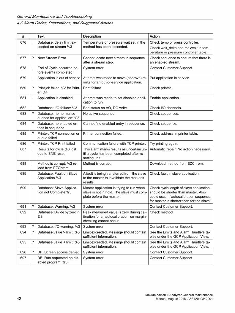
# Text Description Action676 ! Database: delay limit ex‐
ceeded on stream %3Temperature or pressure wait set in the method has been exceeded.
Check temp or press controller. Check wait_delta and maxwait in tem‐perature or pressure controller table.
677 ? Next Stream Error Cannot locate next stream in sequence after a stream step.
Check sequence to ensure that there is an enabled stream.
678 ! End of Cycle occurred be‐fore events completed
System error Contact Customer Support.
679 ! Application is out of service Attempt was made to move (approve) re‐sults for an out-of-service application.
Put application in service.
680 ? Print job failed: %3 for Print‐er: %4
Print failure. Check printer.
681 ! Application is disabled Attempt was made to set disabled appli‐cation to run.
Enable application.
682 ! Database: I/O failure: %3 Bad status on AO, DO write. Check I/O channels.683 ? Database: no normal se‐
quence for application: %3No active sequence. Check sequences.
684 ? Database: no enabled en‐tries in sequence
Cannot find enabled entry in sequence. Check sequence.
685 ? Printer: TCP connection or queue failed
Printer connection failed. Check address in printer table.
686 ? Printer: TCP Print failed Communication failure with TCP printer. Try printing again.687 ! Results for cycle %3 lost
due to SNE resetThis alarm marks results as uncertain un‐til a cycle has been completed after re‐setting unit.
Automatic repair: No action necessary.
688 ! Method is corrupt: %3 re‐load from EZChrom
Method is corrupt. Download method from EZChrom.
689 ! Database: Fault on Slave Application %3
A fault is being transferred from the slave to the master to invalidate the master's results.
Check fault in slave application.
690 ! Database: Slave Applica‐tion not Complete %3
Master application is trying to run when slave is not in hold. The slave must com‐plete before the master.
Check cycle length of slave application; should be shorter than master. Also could occur if autocalibration sequence for master is shorter than for the slave.
691 ? Database: Warning: %3 System error Contact Customer Support.692 ! Database: Divide by zero in
%3Peak measured value is zero during cal‐ibration for an autocalibration, so margin-checking cannot occur.
Check method.
693 ? Database: I/O warning: %3 System error Contact Customer Support.694 ? Database:value > limit: %3 Limit exceeded. Message should contain
sufficient information.See the Limits and Alarm Handlers ta‐bles under the GCP Application View.
695 ? Database value < limit: %3 Limit exceeded. Message should contain sufficient information.
See the Limits and Alarm Handlers ta‐bles under the GCP Application View.
696 ? DB: Screen access denied System error Contact Customer Support.697 ! DB: Run requested on dis‐
abled program: %3System error Contact Customer Support.
General Maintenance and Troubleshooting4.6 Alarm Codes, Descriptions, and Suggested Actions
Maxum edition II Analyzer General Maintenance42 Manual, August 2018, A5E42019842001

# Text Description Action698 ? NAU %3 not available for
communication1. No analyzer reference in host table for Maxum Modbus 2. Cannot open connection to remote an‐alyzer for Maxum Modbus or remote I/O. This is a sometimes-temporary error that indicates a problem in the host table or a network problem.
Check the cables at the sending and receiving ends.
699 ? MODBUS: result is not in address map %3
Cannot find address in map for result or analyzerstatus that came from an ana‐lyzer.
Check modbus_addmap for an incor‐rect anlz attribute.
4.6.6 Alarms 700 - 737
GCP Alarm Descriptions 700 - 736 The following tables list the alarm number (#), type (+ information, ? warning, ! error) alarm text, description, and actions.
# Text Description Action700 ? Network: Analyzer %3 not
availableAnalyzer cannot be opened from NAU to receive message from the DCS.
Check network. Reset SYSCON.
701 ? MODBUS: scale factor or euhi absent for %3
Scale factor or EUHI is absent for scaled results.
Check contents of modbus_addmap.
702 ? MODBUS: host command for %3 invalid; undefined database location
A DCS command has been received for an undefined address.
Check contents of modbus_addmap.
703 ? MODBUS: host command for undefined address: %3
DCS message received that is for an un‐known address.
Check contents of modbus_addmap.
704 ? MODBUS: host cannot write to this address: %3
The address written to by the DCS is not defined with a value_type that the host can send messages to.
Check value_type of address in mod‐bus_addmap.
705 ? MODBUS: mod‐bus_msg_buffer cannot be processed: %3
1. Invalid DCS command was sent to an Optichrom or 2. EUHI, calibrate, stream select, skip stream, run/hold, doset set from host that cannot be located in analyzer table.
1. Cannot clear alarms on optichrom or 2. Check analyzer table to see if entry occurs or wait until analyzer broadcasts.
706 ? MODBUS: cannot locate euhi %3
Cannot find EUHI for result. Check EUHI address in modbus_add‐map_result table.
707 ? Calibration rejected: mar‐gin exceeded for %3
Peak or group margins exceeded on auto calibration.
Check peak or group margins in EZ‐Chrom.
708 ? MODBUS: Data type fail‐ure for address: %3
Data_type mismatch with value_type. Check modbus_addmap. This is usu‐ally self-correcting, but changes should be checked.
709 ! DB: AI averaging %3 Averaging is occurring on an AI with no result designated to receive the average.
Check configuration of AI averaging.
710 ? DB: AI averaging %3 Averaging is occurring on an AI with no result designated to receive the average.
Check configuration of AI averaging.
General Maintenance and Troubleshooting4.6 Alarm Codes, Descriptions, and Suggested Actions
Maxum edition II Analyzer General MaintenanceManual, August 2018, A5E42019842001 43
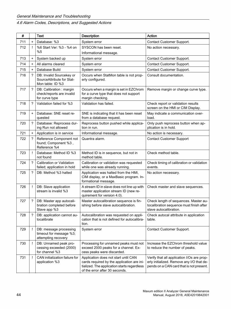
# Text Description Action711 + Database: %3 System error Contact Customer Support.712 ! %6 Start Ver: %3 - %4 on
%5SYSCON has been reset. Informational message.
No action necessary.
713 + System backed up System error Contact Customer Support.714 + All alarms cleared System error Contact Customer Support.715 + Database Build System error Contact Customer Support.716 ? DB: Invalid Sourcekey or
SourceAttribute for Stat‐Mon table: ID %3
Occurs when StatMon table is not prop‐erly configured.
Consult documentation.
717 ? DB: Calibration : margin check/reports are invalid for curve type
Occurs when a margin is set in EZChrom for a curve type that does not support margin checking.
Remove margin or change curve type.
718 ? Validation failed for %3 Validation has failed. Check report or validation results screen on the HMI or CIM Display.
719 + Database: SNE reset re‐quested
SNE is indicating that it has been reset from a database request.
May indicate a communication over‐load.
720 ? Database: Reprocess dur‐ing Run not allowed
Reprocess button pushed while applica‐tion in run.
Only push reprocess button when ap‐plication is in hold.
721 + Application is in service Informational message. No action is necessary.722 ? Reference Component not
found; Component %3 , Reference %4
Quantra alarm. Contact Customer Support
723 ! Database: Method ID %3 not found
Method ID is in sequence, but not in method table.
Check method table.
724 ? Calibration or Validation failed; application in hold
Calibration or validation was requested while one was already running.
Check timing of calibration or validation events.
725 ? DB: Method %3 halted Application was halted from the HMI, CIM display, or a MaxBasic program. In‐formational message.
No action necessary.
726 ! DB: Slave application stream is invalid %3
A stream ID in slave does not line up with master application stream ID (new re‐quirement for version 4.0).
Check master and slave sequences.
727 ? DB: Master app autocali‐bration completed before Slave app %3
Master autocalibration sequence is fin‐ishing before slave autocalibration.
Check length of sequences. Master au‐tocalibration sequence must finish after slave autocalibration.
728 ? DB: application cannot au‐tocalibrate
Autocalibration was requested on appli‐cation that is not defined for autocalibra‐tion.
Check autocal attribute in application table.
729 ! DB: message processing timeout for message %3; attempting recovery
System error Contact Customer Support.
730 ! DB: Unnamed peak pro‐cessing exceeded (2000) for channel %3
Processing for unnamed peaks must not exceed 2000 peaks for a channel. Ex‐cess peaks were discarded.
Increase the EZChrom threshold value to reduce the number of peaks.
731 ! CAN initialization failure for application %3
Application does not start until CAN cards required by the application are ini‐tialized. The application starts regardless of the error after 30 seconds.
Verify that all application I/Os are prop‐erly initialized. Remove any I/O that de‐pends on a CAN card that is not present.
General Maintenance and Troubleshooting4.6 Alarm Codes, Descriptions, and Suggested Actions
Maxum edition II Analyzer General Maintenance44 Manual, August 2018, A5E42019842001
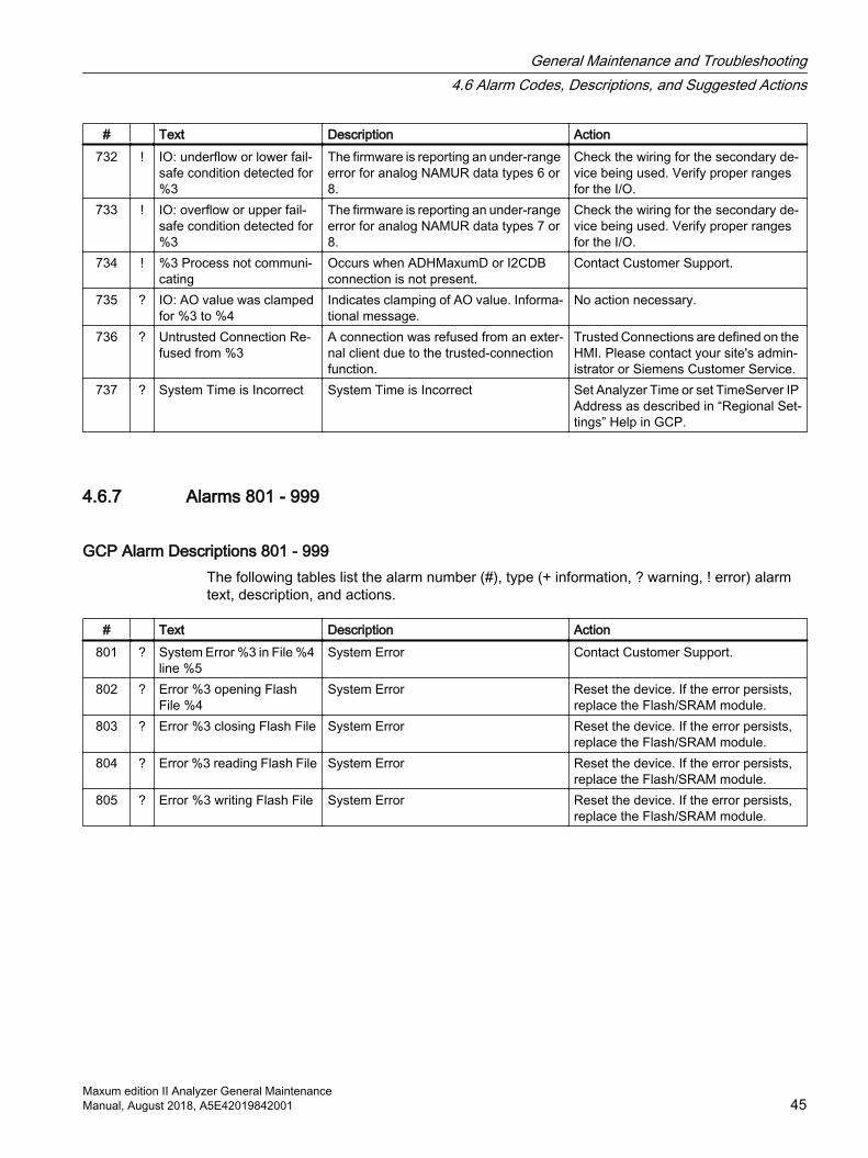
# Text Description Action732 ! IO: underflow or lower fail‐
safe condition detected for %3
The firmware is reporting an under-range error for analog NAMUR data types 6 or 8.
Check the wiring for the secondary de‐vice being used. Verify proper ranges for the I/O.
733 ! IO: overflow or upper fail‐safe condition detected for %3
The firmware is reporting an under-range error for analog NAMUR data types 7 or 8.
Check the wiring for the secondary de‐vice being used. Verify proper ranges for the I/O.
734 ! %3 Process not communi‐cating
Occurs when ADHMaxumD or I2CDB connection is not present.
Contact Customer Support.
735 ? IO: AO value was clamped for %3 to %4
Indicates clamping of AO value. Informa‐tional message.
No action necessary.
736 ? Untrusted Connection Re‐fused from %3
A connection was refused from an exter‐nal client due to the trusted-connection function.
Trusted Connections are defined on the HMI. Please contact your site's admin‐istrator or Siemens Customer Service.
737 ? System Time is Incorrect System Time is Incorrect Set Analyzer Time or set TimeServer IP Address as described in “Regional Set‐tings” Help in GCP.
4.6.7 Alarms 801 - 999
GCP Alarm Descriptions 801 - 999The following tables list the alarm number (#), type (+ information, ? warning, ! error) alarm text, description, and actions.
# Text Description Action801 ? System Error %3 in File %4
line %5System Error Contact Customer Support.
802 ? Error %3 opening Flash File %4
System Error Reset the device. If the error persists, replace the Flash/SRAM module.
803 ? Error %3 closing Flash File System Error Reset the device. If the error persists, replace the Flash/SRAM module.
804 ? Error %3 reading Flash File System Error Reset the device. If the error persists, replace the Flash/SRAM module.
805 ? Error %3 writing Flash File System Error Reset the device. If the error persists, replace the Flash/SRAM module.
General Maintenance and Troubleshooting4.6 Alarm Codes, Descriptions, and Suggested Actions
Maxum edition II Analyzer General MaintenanceManual, August 2018, A5E42019842001 45

# Text Description Action806 ? Memory Corruption Error
from Task %3An attempt to free a block of memory was unsuccessful because the header was overwritten. The block of memory was not returned to the free pool.
1. Save a fresh copy of the database to your Maxum Workstation. 2. Connect to the SYSCON Debug port with hyperterminal or equivalent with ‘save to file’ turned on. 3. Type the login and password individ‐ually when prompted (maxum, maxum) 4. Type each of the diagnostic com‐mands one at a time from the following list: ps, id, fr, st a, ck netstat, ifstatus, uptime. 5. Send the debug file and the .amd file to Customer Support.
807 + Region 0 Memory Low: %3 The amount of free memory in the SY‐SCON is low.
Verify the amount of memory installed in the SYSCON. Contact Customer Support.
808 + Excessive Network Com‐munications
The internal network communication buf‐fers (PNA buffers) are abnormally low. This indicates that the network traffic to the analyzer is abnormally high.
Investigate the cause of the high net‐work traffic.
809 + System is excessively busy This is an overload situation, the process‐or cannot keep up with the requests.
To reduce processor load:● Reduce the size of the Modbus
table. ● Reduce the number and poll rate of
AIs and DIs.● Reduce the number of concurrent
applications running.● Reduce the communication burden
with Optichrom analyzers.810 ? Invalid dbdat file The db.dat file, containing the 'cold' da‐
tabase on a Compact flash system, is missing or invalid. This may happen if the system was reset or powered down during a user initiated save to flash (initi‐ated from the HMI, CIM display, or the workstation).
Perform a manual save to flash as soon as possible in order to have a valid db.dat file.
811 + Excessive Maxum broad‐casts were dropped
Other analyzers on the network are gen‐erating network broadcast messages at an abnormal rate (greater than 200/min). The excessive traffic is ignored. As a re‐sult, the status of the analyzers in the an‐alyzer table may not be up to date.
Investigate the network traffic. Contact Customer Support for assistance.
812 ? Network communication overload
The internal network communication buf‐fers (PNA buffers) are full; the system may not function normally.
Reset the device. Contact Customer Support.
813 + SYSCON-SNE Comm De‐bug: %3
Debugging information, for internal use. No action necessary.
814 ? Invalid CMOS time, check the battery
The built-in SYSCON clock has an inva‐lid time.
Check SYSCON clock battery and re‐place if needed.
General Maintenance and Troubleshooting4.6 Alarm Codes, Descriptions, and Suggested Actions
Maxum edition II Analyzer General Maintenance46 Manual, August 2018, A5E42019842001
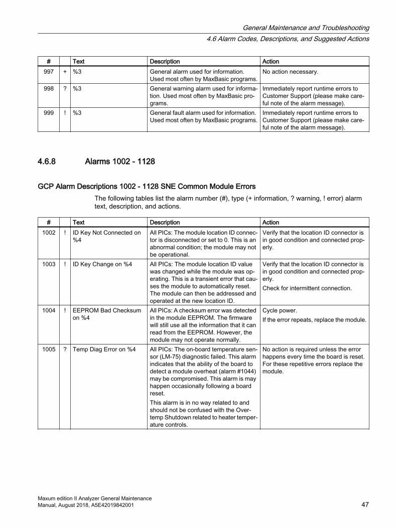
# Text Description Action997 + %3 General alarm used for information.
Used most often by MaxBasic programs.No action necessary.
998 ? %3 General warning alarm used for informa‐tion. Used most often by MaxBasic pro‐grams.
Immediately report runtime errors to Customer Support (please make care‐ful note of the alarm message).
999 ! %3 General fault alarm used for information. Used most often by MaxBasic programs.
Immediately report runtime errors to Customer Support (please make care‐ful note of the alarm message).
4.6.8 Alarms 1002 - 1128
GCP Alarm Descriptions 1002 - 1128 SNE Common Module ErrorsThe following tables list the alarm number (#), type (+ information, ? warning, ! error) alarm text, description, and actions.
# Text Description Action1002 ! ID Key Not Connected on
%4All PICs: The module location ID connec‐tor is disconnected or set to 0. This is an abnormal condition; the module may not be operational.
Verify that the location ID connector is in good condition and connected prop‐erly.
1003 ! ID Key Change on %4 All PICs: The module location ID value was changed while the module was op‐erating. This is a transient error that cau‐ses the module to automatically reset. The module can then be addressed and operated at the new location ID.
Verify that the location ID connector is in good condition and connected prop‐erly. Check for intermittent connection.
1004 ! EEPROM Bad Checksum on %4
All PICs: A checksum error was detected in the module EEPROM. The firmware will still use all the information that it can read from the EEPROM. However, the module may not operate normally.
Cycle power. If the error repeats, replace the module.
1005 ? Temp Diag Error on %4 All PICs: The on-board temperature sen‐sor (LM-75) diagnostic failed. This alarm indicates that the ability of the board to detect a module overheat (alarm #1044) may be compromised. This alarm is may happen occasionally following a board reset. This alarm is in no way related to and should not be confused with the Over‐temp Shutdown related to heater temper‐ature controls.
No action is required unless the error happens every time the board is reset. For these repetitive errors replace the module.
General Maintenance and Troubleshooting4.6 Alarm Codes, Descriptions, and Suggested Actions
Maxum edition II Analyzer General MaintenanceManual, August 2018, A5E42019842001 47
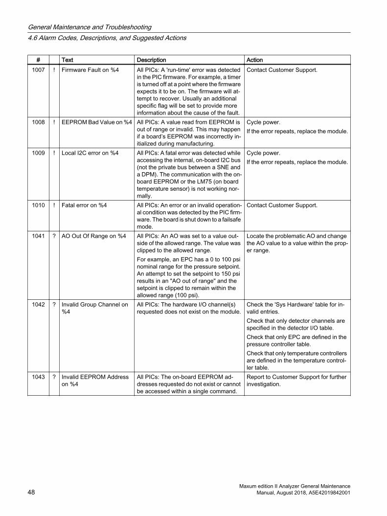
# Text Description Action1007 ! Firmware Fault on %4 All PICs: A 'run-time' error was detected
in the PIC firmware. For example, a timer is turned off at a point where the firmware expects it to be on. The firmware will at‐tempt to recover. Usually an additional specific flag will be set to provide more information about the cause of the fault.
Contact Customer Support.
1008 ! EEPROM Bad Value on %4 All PICs: A value read from EEPROM is out of range or invalid. This may happen if a board’s EEPROM was incorrectly in‐itialized during manufacturing.
Cycle power. If the error repeats, replace the module.
1009 ! Local I2C error on %4 All PICs: A fatal error was detected while accessing the internal, on-board I2C bus (not the private bus between a SNE and a DPM). The communication with the on-board EEPROM or the LM75 (on board temperature sensor) is not working nor‐mally.
Cycle power. If the error repeats, replace the module.
1010 ! Fatal error on %4 All PICs: An error or an invalid operation‐al condition was detected by the PIC firm‐ware. The board is shut down to a failsafe mode.
Contact Customer Support.
1041 ? AO Out Of Range on %4 All PICs: An AO was set to a value out‐side of the allowed range. The value was clipped to the allowed range. For example, an EPC has a 0 to 100 psi nominal range for the pressure setpoint. An attempt to set the setpoint to 150 psi results in an "AO out of range" and the setpoint is clipped to remain within the allowed range (100 psi).
Locate the problematic AO and change the AO value to a value within the prop‐er range.
1042 ? Invalid Group Channel on %4
All PICs: The hardware I/O channel(s) requested does not exist on the module.
Check the 'Sys Hardware' table for in‐valid entries. Check that only detector channels are specified in the detector I/O table. Check that only EPC are defined in the pressure controller table. Check that only temperature controllers are defined in the temperature control‐ler table.
1043 ? Invalid EEPROM Address on %4
All PICs: The on-board EEPROM ad‐dresses requested do not exist or cannot be accessed within a single command.
Report to Customer Support for further investigation.
General Maintenance and Troubleshooting4.6 Alarm Codes, Descriptions, and Suggested Actions
Maxum edition II Analyzer General Maintenance48 Manual, August 2018, A5E42019842001
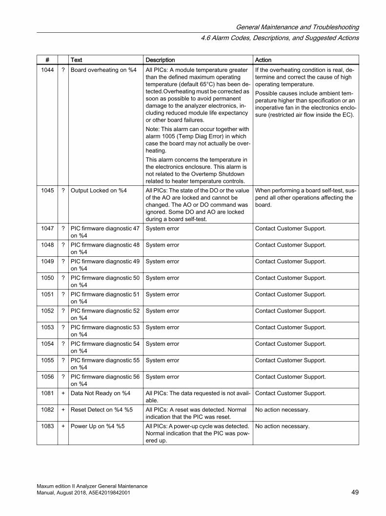
# Text Description Action1044 ? Board overheating on %4 All PICs: A module temperature greater
than the defined maximum operating temperature (default 65°C) has been de‐tected.Overheating must be corrected as soon as possible to avoid permanent damage to the analyzer electronics, in‐cluding reduced module life expectancy or other board failures.Note: This alarm can occur together with alarm 1005 (Temp Diag Error) in which case the board may not actually be over‐heating. This alarm concerns the temperature in the electronics enclosure. This alarm is not related to the Overtemp Shutdown related to heater temperature controls.
If the overheating condition is real, de‐termine and correct the cause of high operating temperature. Possible causes include ambient tem‐perature higher than specification or an inoperative fan in the electronics enclo‐sure (restricted air flow inside the EC).
1045 ? Output Locked on %4 All PICs: The state of the DO or the value of the AO are locked and cannot be changed. The AO or DO command was ignored. Some DO and AO are locked during a board self-test.
When performing a board self-test, sus‐pend all other operations affecting the board.
1047 ? PIC firmware diagnostic 47 on %4
System error Contact Customer Support.
1048 ? PIC firmware diagnostic 48 on %4
System error Contact Customer Support.
1049 ? PIC firmware diagnostic 49 on %4
System error Contact Customer Support.
1050 ? PIC firmware diagnostic 50 on %4
System error Contact Customer Support.
1051 ? PIC firmware diagnostic 51 on %4
System error Contact Customer Support.
1052 ? PIC firmware diagnostic 52 on %4
System error Contact Customer Support.
1053 ? PIC firmware diagnostic 53 on %4
System error Contact Customer Support.
1054 ? PIC firmware diagnostic 54 on %4
System error Contact Customer Support.
1055 ? PIC firmware diagnostic 55 on %4
System error Contact Customer Support.
1056 ? PIC firmware diagnostic 56 on %4
System error Contact Customer Support.
1081 + Data Not Ready on %4 All PICs: The data requested is not avail‐able.
Contact Customer Support.
1082 + Reset Detect on %4 %5 All PICs: A reset was detected. Normal indication that the PIC was reset.
No action necessary.
1083 + Power Up on %4 %5 All PICs: A power-up cycle was detected. Normal indication that the PIC was pow‐ered up.
No action necessary.
General Maintenance and Troubleshooting4.6 Alarm Codes, Descriptions, and Suggested Actions
Maxum edition II Analyzer General MaintenanceManual, August 2018, A5E42019842001 49
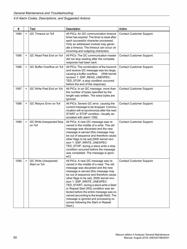
# Text Description Action1084 + I2C Timeout on %4 All PICs: An I2C communication timeout
timer has expired. The timer is reset after each successful character processed. Only an addressed module may gener‐ate a timeout. The timeout can occur on incoming and outgoing characters.
Contact Customer Support.
1085 + I2C Read Past End on %4 All PICs: The I2C communication master did not stop reading after the complete response had been sent.
Contact Customer Support.
1086 + I2C Buffer Overflow on %4 All PICs: The combination of the transmit and receive I2C message was too large, causing a buffer overflow. (With kernel revision 1: SSP_READ_UNEXPEC‐TED_STOP, a stop condition occurred before the end of the response).
Contact Customer Support.
1087 + I2C Write Past End on %4 All PICs: In an I2C message, more than the number of bytes specified by the length was written. The extra bytes are ignored.
Contact Customer Support.
1088 + I2C Resync Error on %4 All PICs: Severe I2C error, causing the current message to be dropped. Commu‐nication will re-synchronize after the next START or STOP condition. Usually as‐sociated with alarm 1092.
Contact Customer Support.
1089 + I2C Write Unexpected Stop on %4
All PICs: A new I2C message was re‐ceived in the middle of a write. The old message was discarded and the new message is served (this message may be out of sequence and therefore cause other flags to be set).[With kernel revi‐sion 1: SSP_WRITE_UNEXPEC‐TED_STOP, during a slave write a stop condition occurred before the message was completed. The message is ignor‐ed.]
Contact Customer Support.
1090 + I2C Write Unexpected Start on %4
All PICs: A new I2C message was re‐ceived in the middle of a read. The old message was discarded and the new message is served (this message may be out of sequence and therefore cause other flags to be set). [With kernel revi‐sion 1: SSP_WRITE_UNEXPEC‐TED_START, during a slave write a Start or Repeat Start (RS) condition was de‐tected before the entire message was re‐ceived (according to the length field). The message is ignored and processing re‐sumes following the Start or Repeat Start.]
Contact Customer Support.
General Maintenance and Troubleshooting4.6 Alarm Codes, Descriptions, and Suggested Actions
Maxum edition II Analyzer General Maintenance50 Manual, August 2018, A5E42019842001
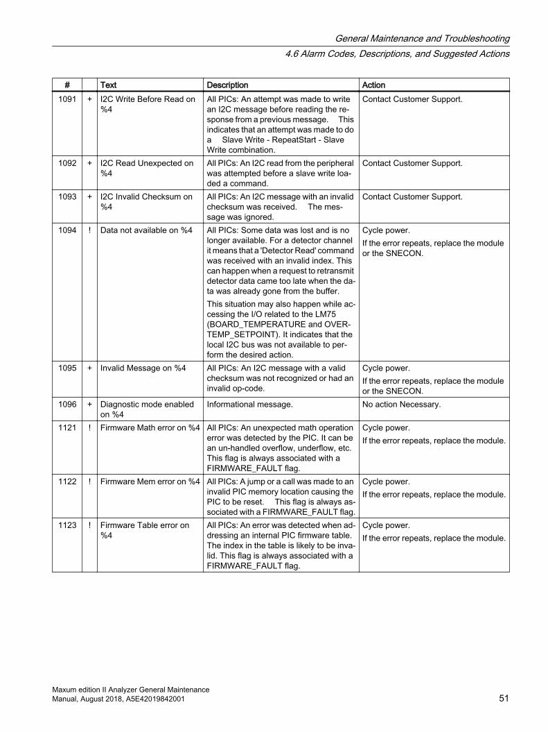
# Text Description Action1091 + I2C Write Before Read on
%4All PICs: An attempt was made to write an I2C message before reading the re‐sponse from a previous message. This indicates that an attempt was made to do a Slave Write - RepeatStart - Slave Write combination.
Contact Customer Support.
1092 + I2C Read Unexpected on %4
All PICs: An I2C read from the peripheral was attempted before a slave write loa‐ded a command.
Contact Customer Support.
1093 + I2C Invalid Checksum on %4
All PICs: An I2C message with an invalid checksum was received. The mes‐sage was ignored.
Contact Customer Support.
1094 ! Data not available on %4 All PICs: Some data was lost and is no longer available. For a detector channel it means that a 'Detector Read' command was received with an invalid index. This can happen when a request to retransmit detector data came too late when the da‐ta was already gone from the buffer. This situation may also happen while ac‐cessing the I/O related to the LM75 (BOARD_TEMPERATURE and OVER‐TEMP_SETPOINT). It indicates that the local I2C bus was not available to per‐form the desired action.
Cycle power. If the error repeats, replace the module or the SNECON.
1095 + Invalid Message on %4 All PICs: An I2C message with a valid checksum was not recognized or had an invalid op-code.
Cycle power. If the error repeats, replace the module or the SNECON.
1096 + Diagnostic mode enabled on %4
Informational message. No action Necessary.
1121 ! Firmware Math error on %4 All PICs: An unexpected math operation error was detected by the PIC. It can be an un-handled overflow, underflow, etc. This flag is always associated with a FIRMWARE_FAULT flag.
Cycle power.If the error repeats, replace the module.
1122 ! Firmware Mem error on %4 All PICs: A jump or a call was made to an invalid PIC memory location causing the PIC to be reset. This flag is always as‐sociated with a FIRMWARE_FAULT flag.
Cycle power.If the error repeats, replace the module.
1123 ! Firmware Table error on %4
All PICs: An error was detected when ad‐dressing an internal PIC firmware table. The index in the table is likely to be inva‐lid. This flag is always associated with a FIRMWARE_FAULT flag.
Cycle power.If the error repeats, replace the module.
General Maintenance and Troubleshooting4.6 Alarm Codes, Descriptions, and Suggested Actions
Maxum edition II Analyzer General MaintenanceManual, August 2018, A5E42019842001 51

# Text Description Action1124 ! Firmware Watchdog on %4 All PICs: The PIC watch dog timer has
expired causing a module reset. This flag is always associated with a FIRM‐WARE_FAULT flag. It can be an indica‐tion that the I2C clock or data line was held low for more than the timeout dura‐tion (nominally 30 ms). It can also indi‐cate that the PIC oscillator is not working normally.
Cycle power.If the error repeats, replace the module.
1125 ! Firmware System Monitor on %4
All PICs: The background system moni‐toring task has discovered a problem causing the PIC to be reset. It can be that the interrupt or timer were disabled when they should have been enabled, or some similar error. This flag is always asso‐ciated with a FIRMWARE_FAULT flag.
Cycle power.If the error repeats, replace the module.
1126 ! Firmware Application on %4
All PICs: A general PIC firmware error was encountered causing a board reset.
Cycle power.If the error repeats, replace the module.
1127 ! Firmware Stack Overflow on %4
An abnormal condition was detected in the firmware of a specified module.
Reset the device. If the condition per‐sists, replace the affected module.
1128 ! Firmware Unknown Reset on %4
An abnormal condition was detected in the firmware of a specified module.
Reset the device. If the condition per‐sists, replace the affected module.
4.6.9 Alarms 1317 - 1319
GCP Alarm Descriptions 1317 - 1319The following tables list the alarm number (#), type (+ information, ? warning, ! error) alarm text, description, and actions.
# ! Text Description Action1317
! Valve Switch Error on %4
SVCM PIC: The SVCM firmware has detected an invalid condition in the circuit driving the solenoid valves. One or more valves is likely to be malfunctioning.
Replace the module.
1318
! J10 Disconnected on %4
SVCM PIC: The SVCM J10 con‐nector is not properly connected and the corresponding bank of solenoids may not work.
Check the J10 connection.
1319
! J11 Disconnected on %4
SVCM PIC: The SVCM J11 con‐nector is not properly connected and the corresponding bank of solenoids may not work.
Check the J11 connection.
General Maintenance and Troubleshooting4.6 Alarm Codes, Descriptions, and Suggested Actions
Maxum edition II Analyzer General Maintenance52 Manual, August 2018, A5E42019842001
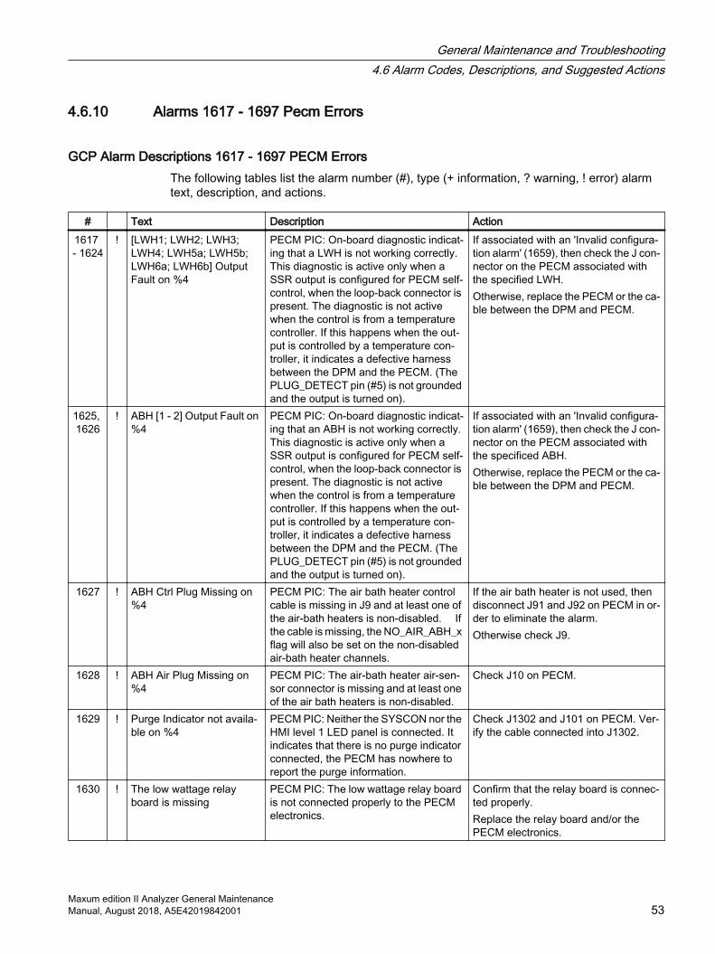
4.6.10 Alarms 1617 - 1697 Pecm Errors
GCP Alarm Descriptions 1617 - 1697 PECM ErrorsThe following tables list the alarm number (#), type (+ information, ? warning, ! error) alarm text, description, and actions.
# Text Description Action1617 - 1624
! [LWH1; LWH2; LWH3; LWH4; LWH5a; LWH5b; LWH6a; LWH6b] Output Fault on %4
PECM PIC: On-board diagnostic indicat‐ing that a LWH is not working correctly. This diagnostic is active only when a SSR output is configured for PECM self-control, when the loop-back connector is present. The diagnostic is not active when the control is from a temperature controller. If this happens when the out‐put is controlled by a temperature con‐troller, it indicates a defective harness between the DPM and the PECM. (The PLUG_DETECT pin (#5) is not grounded and the output is turned on).
If associated with an 'Invalid configura‐tion alarm' (1659), then check the J con‐nector on the PECM associated with the specified LWH. Otherwise, replace the PECM or the ca‐ble between the DPM and PECM.
1625, 1626
! ABH [1 - 2] Output Fault on %4
PECM PIC: On-board diagnostic indicat‐ing that an ABH is not working correctly. This diagnostic is active only when a SSR output is configured for PECM self-control, when the loop-back connector is present. The diagnostic is not active when the control is from a temperature controller. If this happens when the out‐put is controlled by a temperature con‐troller, it indicates a defective harness between the DPM and the PECM. (The PLUG_DETECT pin (#5) is not grounded and the output is turned on).
If associated with an 'Invalid configura‐tion alarm' (1659), then check the J con‐nector on the PECM associated with the specificed ABH. Otherwise, replace the PECM or the ca‐ble between the DPM and PECM.
1627 ! ABH Ctrl Plug Missing on %4
PECM PIC: The air bath heater control cable is missing in J9 and at least one of the air-bath heaters is non-disabled. If the cable is missing, the NO_AIR_ABH_x flag will also be set on the non-disabled air-bath heater channels.
If the air bath heater is not used, then disconnect J91 and J92 on PECM in or‐der to eliminate the alarm. Otherwise check J9.
1628 ! ABH Air Plug Missing on %4
PECM PIC: The air-bath heater air-sen‐sor connector is missing and at least one of the air bath heaters is non-disabled.
Check J10 on PECM.
1629 ! Purge Indicator not availa‐ble on %4
PECM PIC: Neither the SYSCON nor the HMI level 1 LED panel is connected. It indicates that there is no purge indicator connected, the PECM has nowhere to report the purge information.
Check J1302 and J101 on PECM. Ver‐ify the cable connected into J1302.
1630 ! The low wattage relay board is missing
PECM PIC: The low wattage relay board is not connected properly to the PECM electronics.
Confirm that the relay board is connec‐ted properly.Replace the relay board and/or the PECM electronics.
General Maintenance and Troubleshooting4.6 Alarm Codes, Descriptions, and Suggested Actions
Maxum edition II Analyzer General MaintenanceManual, August 2018, A5E42019842001 53
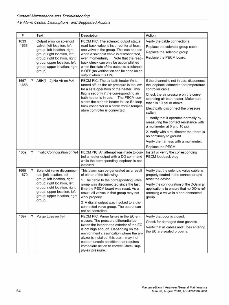
# Text Description Action1633 - 1638
! Output error on solenoid valve, [left location, left group; left location, right group; right location, left group; right location, right group; upper location, left group; upper location, right group]
PECM PIC: The solenoid output status read-back value is incorrect for at least one valve in the group. This can happen when a solenoid cable is disconnected, even momentarily. Note that the read-back check can only be accomplished when the state of the output to a solenoid is OFF (no verification can be done on an output when it is ON).
Verify the cable connections. Replace the solenoid group cable. Replace the solenoid group. Replace the PECM board.
1657 - 1658
? ABH[1 - 2] No Air on %4 PECM PIC: The air bath heater #n is turned off, as the air pressure is too low for a safe operation of the heater. This flag is set only if the corresponding air bath heater is in use. The PECM con‐siders the air bath heater in use if a loop‐back connector or a cable from a temper‐ature controller is connected.
If the channel is not in use, disconnect the loopback connector or temperature controller cable. Check the air pressure on the corre‐sponding air bath heater. Make sure that it is 10 psi or above. Electrically disconnect the pressure switch:1. Verify that it operates normally by measuring the contact resistance with a multimeter at 0 and 10 psi. 2. Verify with a multimeter that there is no continuity to ground.Verify the harness with a multimeter. Replace the PECM.
1659 ? Invalid Configuration on %4 PECM PIC: An attempt was made to con‐trol a heater output with a DO command while the corresponding loopback is not installed.
Install or verify the corresponding PECM loopback plug.
1665 - 1670
? Solenoid valve disconnec‐ted, [left location, left group; left location, right group; right location, left group; right location, right group; upper location, left group; upper location, right group]
This alarm can be generated as a result of either of the following:1. The cable to the corresponding valve group was disconnected since the last time the PECM board was reset. As a result, all valves in that group may not work properly. 2 A digital output was invoked to a dis‐connected valve group. The output can‐not be controlled.
Verify that the solenoid valve cable is properly seated in the connector and reset the device. Verify the configuration of the DOs in all applications to ensure that no DO is ref‐erencing a valve in a non-connected group.
1697 ? Purge Loss on %4 PECM PIC: Purge failure in the EC en‐closure. The pressure differential be‐tween the interior and exterior of the EC is not high enough. Depending on the environment classification where the an‐alyzer is installed, this alarm may indi‐cate an unsafe condition that requires immediate action to correct.Check sup‐ply-air pressure.
Verify that door is closed.Check for damaged door gaskets.Verify that all cables and tubes entering the EC are sealed properly.
General Maintenance and Troubleshooting4.6 Alarm Codes, Descriptions, and Suggested Actions
Maxum edition II Analyzer General Maintenance54 Manual, August 2018, A5E42019842001

4.6.11 Alarms 1917 - 2005 DPM TCD
GCP Alarm Descriptions 1917 - 1999 DPM ErrorsThe following tables list the alarm number (#), type (+ information, ? warning, ! error) alarm text, description, and actions.
# Text Description Action1917 ! Balance Hardware Failure
TCD L %5 on %4System error Contact Customer Support.
1918 ! Balance Hardware Failure TCD U %5 on %4
System error Contact Customer Support.
1919, 1920
! A/D Failure TCD [L; U] %5 on %4
TCD DPM Detector PIC: Set when the corresponding Analog to Digital Convert‐er hardware does not work properly. The flag will be set if the A/D internal calibra‐tion cycle is not completed within a pre-determined period of time or the A/D does not report any valid data within a pre-defined timeout period. Note: A firmware problem affecting the version 1.000 of the TCD detector PIC may cause an A/D failure flag to show-up occasionally following a PIC reset. This is not a sign of a defective A/D converter.
Cycle power. If the error repeats con‐sistently, replace the module.
1921 ! PIC Timeout on %4 System error Contact Customer Support.1922 ! Incompatible Hardware on
%4TCD DPM Detector PIC: The PIC firm‐ware is not compatible with the DPM board.
Replace the module.
1925 ? Glow Plug bad FID DPM Detector PIC: The glow plug is not working correctly. The diagnostic is performed when the board is reset or when an attempt is made to light the flame. The hardware diagnostic verifies that a minimum current and voltage is present, checking for a short and open glow plug. This may also indicate that a spark igniter that is not connected prop‐erly.
Confirm that the glow plug or spark ig‐niter cable is securely inserted in the corresponding connector. Replace the glow plug. Replace the DPM.
1926 ! Invalid PIC index DPM Detector PIC: The PIC index is not valid, the DPM board is not working nor‐mally.
Replace the module.
1927 ! Mezzanine module discon‐nected
FID DPM Detector PIC: The mezzanine-module ID value is 0 or 15 indicating that no module is present or is malfunctioning.
Verify that the mezzanine module is properly connected. Replace the module on the DPM. Replace the DPM.
1928 ! Mezzanine-module ID changed
FID DPM Detector PIC: The mezzanine-module ID value has changed since the last time the board was reset. Indicates a bad contact or a bad component.
Verify that the mezzanine module is properly connected. Replace the module on the DPM. Replace the DPM.
General Maintenance and Troubleshooting4.6 Alarm Codes, Descriptions, and Suggested Actions
Maxum edition II Analyzer General MaintenanceManual, August 2018, A5E42019842001 55
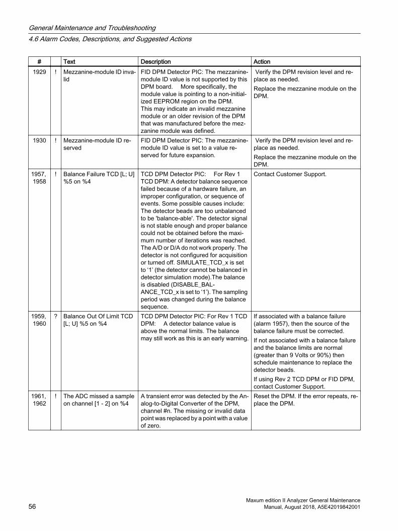
# Text Description Action1929 ! Mezzanine-module ID inva‐
lidFID DPM Detector PIC: The mezzanine-module ID value is not supported by this DPM board. More specifically, the module value is pointing to a non-initial‐ized EEPROM region on the DPM. This may indicate an invalid mezzanine module or an older revision of the DPM that was manufactured before the mez‐zanine module was defined.
Verify the DPM revision level and re‐place as needed. Replace the mezzanine module on the DPM.
1930 ! Mezzanine-module ID re‐served
FID DPM Detector PIC: The mezzanine-module ID value is set to a value re‐served for future expansion.
Verify the DPM revision level and re‐place as needed. Replace the mezzanine module on the DPM.
1957, 1958
! Balance Failure TCD [L; U] %5 on %4
TCD DPM Detector PIC: For Rev 1 TCD DPM: A detector balance sequence failed because of a hardware failure, an improper configuration, or sequence of events. Some possible causes include: The detector beads are too unbalanced to be 'balance-able'. The detector signal is not stable enough and proper balance could not be obtained before the maxi‐mum number of iterations was reached. The A/D or D/A do not work properly. The detector is not configured for acquisition or turned off. SIMULATE_TCD_x is set to ‘1’ (the detector cannot be balanced in detector simulation mode).The balance is disabled (DISABLE_BAL‐ANCE_TCD_x is set to ‘1’). The sampling period was changed during the balance sequence.
Contact Customer Support.
1959, 1960
? Balance Out Of Limit TCD [L; U] %5 on %4
TCD DPM Detector PIC: For Rev 1 TCD DPM: A detector balance value is above the normal limits. The balance may still work as this is an early warning.
If associated with a balance failure (alarm 1957), then the source of the balance failure must be corrected.If not associated with a balance failure and the balance limits are normal (greater than 9 Volts or 90%) then schedule maintenance to replace the detector beads.If using Rev 2 TCD DPM or FID DPM, contact Customer Support.
1961, 1962
! The ADC missed a sample on channel [1 - 2] on %4
A transient error was detected by the An‐alog-to-Digital Converter of the DPM, channel #n. The missing or invalid data point was replaced by a point with a value of zero.
Reset the DPM. If the error repeats, re‐place the DPM.
General Maintenance and Troubleshooting4.6 Alarm Codes, Descriptions, and Suggested Actions
Maxum edition II Analyzer General Maintenance56 Manual, August 2018, A5E42019842001
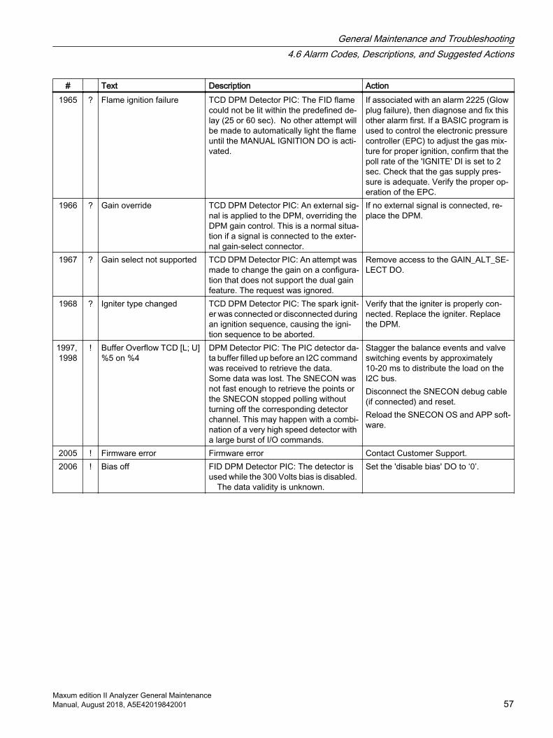
# Text Description Action1965 ? Flame ignition failure TCD DPM Detector PIC: The FID flame
could not be lit within the predefined de‐lay (25 or 60 sec). No other attempt will be made to automatically light the flame until the MANUAL IGNITION DO is acti‐vated.
If associated with an alarm 2225 (Glow plug failure), then diagnose and fix this other alarm first. If a BASIC program is used to control the electronic pressure controller (EPC) to adjust the gas mix‐ture for proper ignition, confirm that the poll rate of the 'IGNITE' DI is set to 2 sec. Check that the gas supply pres‐sure is adequate. Verify the proper op‐eration of the EPC.
1966 ? Gain override TCD DPM Detector PIC: An external sig‐nal is applied to the DPM, overriding the DPM gain control. This is a normal situa‐tion if a signal is connected to the exter‐nal gain-select connector.
If no external signal is connected, re‐place the DPM.
1967 ? Gain select not supported TCD DPM Detector PIC: An attempt was made to change the gain on a configura‐tion that does not support the dual gain feature. The request was ignored.
Remove access to the GAIN_ALT_SE‐LECT DO.
1968 ? Igniter type changed TCD DPM Detector PIC: The spark ignit‐er was connected or disconnected during an ignition sequence, causing the igni‐tion sequence to be aborted.
Verify that the igniter is properly con‐nected. Replace the igniter. Replace the DPM.
1997, 1998
! Buffer Overflow TCD [L; U] %5 on %4
DPM Detector PIC: The PIC detector da‐ta buffer filled up before an I2C command was received to retrieve the data. Some data was lost. The SNECON was not fast enough to retrieve the points or the SNECON stopped polling without turning off the corresponding detector channel. This may happen with a combi‐nation of a very high speed detector with a large burst of I/O commands.
Stagger the balance events and valve switching events by approximately 10-20 ms to distribute the load on the I2C bus.Disconnect the SNECON debug cable (if connected) and reset.Reload the SNECON OS and APP soft‐ware.
2005 ! Firmware error Firmware error Contact Customer Support.2006 ! Bias off FID DPM Detector PIC: The detector is
used while the 300 Volts bias is disabled. The data validity is unknown.
Set the 'disable bias' DO to ‘0’.
General Maintenance and Troubleshooting4.6 Alarm Codes, Descriptions, and Suggested Actions
Maxum edition II Analyzer General MaintenanceManual, August 2018, A5E42019842001 57

4.6.12 Alarms 2217 - 2306 DPM FID
GCP Alarm Descriptions 2217 - 2306 DPM ErrorsThe following tables list the alarm number (#), type (+ information, ? warning, ! error) alarm text, description, and actions.
# Text Description Action2217 ! Balance Hardware Failure
FID L %5 on %4System error Contact Customer Support.
2218 ! Balance Hardware Failure FID U %5 on %4
System error Contact Customer Support.
2219, 2220
! A/D Failure [FID; TCD] %5 on %4
DPM Detector PIC: Set when the corre‐sponding Analog to Digital Converter hardware does not work properly. The flag will be set if the A/D internal calibra‐tion cycle is not completed within a pre-determined period of time or the A/D does not report any valid data within a pre-defined timeout period.
Cycle power. If the error repeats con‐sistently, replace the module.
2221 ! PIC Timeout on %4 System error Contact Customer Support.2222 ! Incompatible Hardware on
%4The firmware has detected an invalid condition indicating that the hardware is not compatible with the firmware.
Replace the module.
2225 ? Glow Plug Bad on %4 FID DPM Detector PIC: The glow plug is not working correctly. The diagnostic is performed when the board is reset or when an attempt is made to ignite the flame. The hardware diagnostic veri‐fies that a minimum current and voltage is present, checking for a short and open glow plug. This may also indicate that a spark igniter is not connected properly.
Confirm that the glow plug or spark ig‐niter cable is securely inserted in the connector. Replace the glow plug. Replace the DPM.
2226 ! Invalid PIC index DPM Detector PIC: The PIC index is not valid; the DPM board is not working nor‐mally.
Replace the module.
2227 ! Mezzanine module discon‐nected
FID DPM Detector PIC: The mezzanine-module ID value is 0 or 15 indicating that no module is present or is malfunctioning.
Verify that the mezzanine module is properly connected. Replace the module on the DPM. Replace the DPM.
2228 ! Mezzanine-module ID changed
FID DPM Detector PIC: The mezzanine-module ID value has changed since the last time the board was reset. Indicates a bad contact or a bad component.
Verify that the mezzanine module is properly connected. Replace the module on the DPM. Replace the DPM.
General Maintenance and Troubleshooting4.6 Alarm Codes, Descriptions, and Suggested Actions
Maxum edition II Analyzer General Maintenance58 Manual, August 2018, A5E42019842001
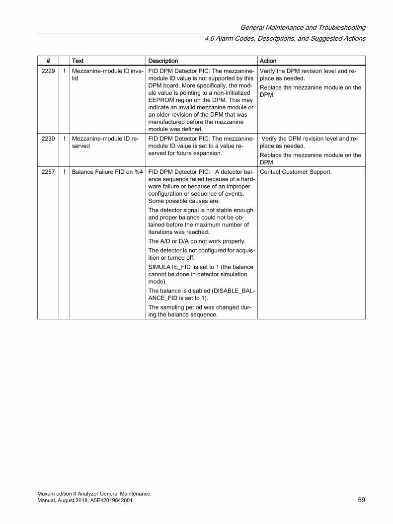
# Text Description Action2229 ! Mezzanine-module ID inva‐
lidFID DPM Detector PIC: The mezzanine-module ID value is not supported by this DPM board. More specifically, the mod‐ule value is pointing to a non-initialized EEPROM region on the DPM. This may indicate an invalid mezzanine module or an older revision of the DPM that was manufactured before the mezzanine module was defined.
Verify the DPM revision level and re‐place as needed. Replace the mezzanine module on the DPM.
2230 ! Mezzanine-module ID re‐served
FID DPM Detector PIC: The mezzanine-module ID value is set to a value re‐served for future expansion.
Verify the DPM revision level and re‐place as needed. Replace the mezzanine module on the DPM.
2257 ! Balance Failure FID on %4 FID DPM Detector PIC: A detector bal‐ance sequence failed because of a hard‐ware failure or because of an improper configuration or sequence of events. Some possible causes are:The detector signal is not stable enough and proper balance could not be ob‐tained before the maximum number of iterations was reached. The A/D or D/A do not work properly. The detector is not configured for acquis‐ition or turned off. SIMULATE_FID is set to 1 (the balance cannot be done in detector simulation mode).The balance is disabled (DISABLE_BAL‐ANCE_FID is set to 1). The sampling period was changed dur‐ing the balance sequence.
Contact Customer Support.
General Maintenance and Troubleshooting4.6 Alarm Codes, Descriptions, and Suggested Actions
Maxum edition II Analyzer General MaintenanceManual, August 2018, A5E42019842001 59

# Text Description Action2258 ! Balance Failure TCD %5
on %4FID DPM Detector PIC: A detector bal‐ance sequence failed because of a hard‐ware failure or because of an improper configuration or sequence of events. Some possible causes are: The detector beads are too mismatched to be balance corrected.The detector signal is not stable enough and proper balance could not be ob‐tained before the maximum number of iterations was reached.The A/D or D/A do not work properly.The detector is not configured for acquis‐ition or turned off. SIMULATE_TCD is set to ‘1’ (the bal‐ance cannot be done in detector simula‐tion mode).The balance is disabled (DISABLE_BAL‐ANCE_TCD is set to ‘1’).The sampling period was changed dur‐ing the balance sequence.
Contact Customer Support.
2259 ? Balance Out Of Limit FID on %4
FID DPM Detector PIC: A detector bal‐ance value is above the normal limits. The balance may still work as this is an early warning.
If associated with a balance failure (alarm 2257), then the source of the balance failure must be corrected.If not associated with a balance failure and the balance limits are normal (greater than 9 Volts or 90%), schedule maintenance to clean or replace the FID detector.
2260 ? Balance Out Of Limit TCD %5 on %4
TCD DPM Detector PIC: A detector bal‐ance value is above the normal limits. The balance may still work as this is an early warning.
If associated with a balance failure (alarm 2258), then the source of the balance failure must be corrected. If not associated with a balance failure and the balance limits are normal (greater than 9 Volts or 90%) then maintenance should be scheduled to replace the de‐tector beads.
2261, 2622
! The ADC missed a sample on channel [1 - 2] on %4
A transient error was detected by the An‐alog-to-Digital Converter of the DPM, channel #n. The missing or invalid data point was replaced by a point with a value of zero.
Reset the DPM. If the error repeats, re‐place the DPM.
2265 ? Flame Ignition Failure on %4
FID DPM Detector PIC: The FID flame could not be ignited within the predefined delay (25 or 60 sec). No other attempt will be made to automatically ignite the flame until the MANUAL IGNITION DO is activated.
If associated with an alarm 2225 (Glow plug failure), then diagnose and fix that alarm first. If a BASIC program is used to control the electronic pressure con‐troller (EPC) to adjust the gas mixture for proper ignition, confirm that the poll rate of the 'IGNITE' DI is set to 2 sec. Verify adequate gas-supply pressure. Verify the proper operation of the EPC.
General Maintenance and Troubleshooting4.6 Alarm Codes, Descriptions, and Suggested Actions
Maxum edition II Analyzer General Maintenance60 Manual, August 2018, A5E42019842001
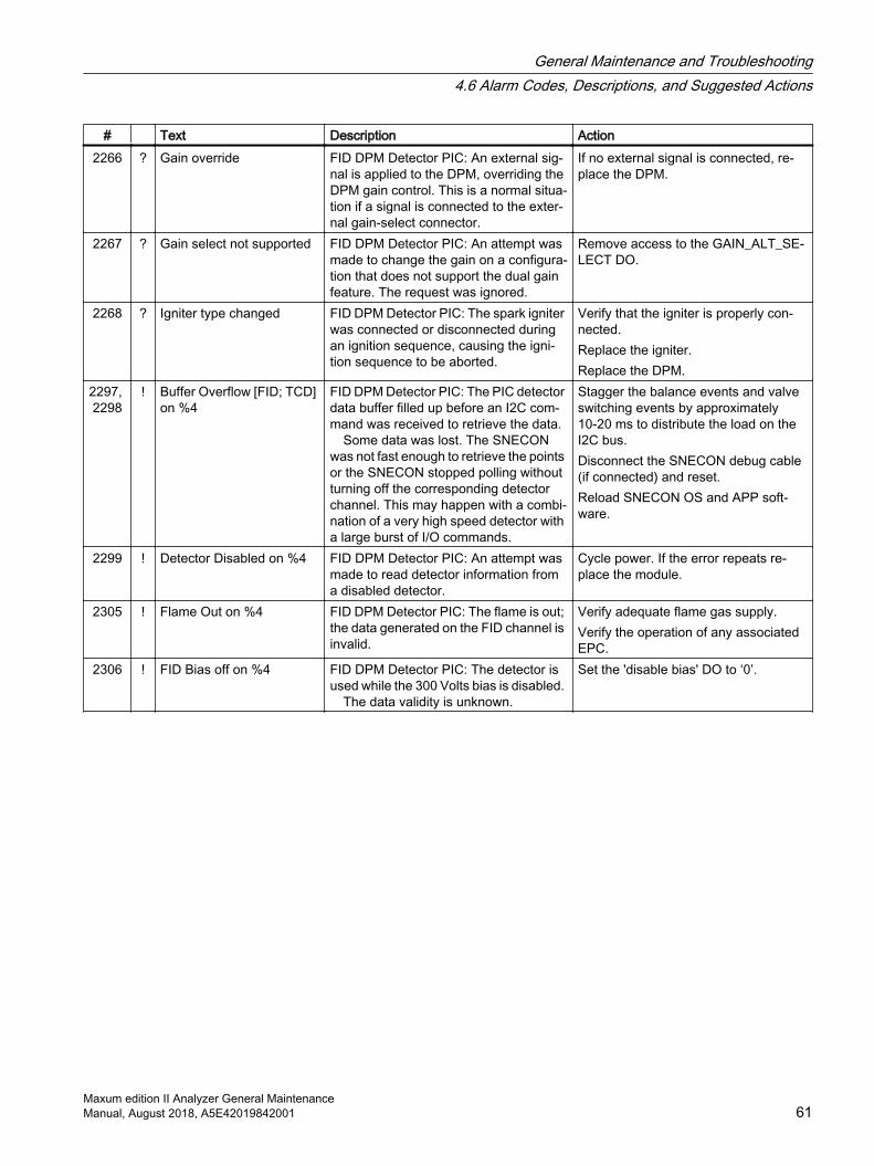
# Text Description Action2266 ? Gain override FID DPM Detector PIC: An external sig‐
nal is applied to the DPM, overriding the DPM gain control. This is a normal situa‐tion if a signal is connected to the exter‐nal gain-select connector.
If no external signal is connected, re‐place the DPM.
2267 ? Gain select not supported FID DPM Detector PIC: An attempt was made to change the gain on a configura‐tion that does not support the dual gain feature. The request was ignored.
Remove access to the GAIN_ALT_SE‐LECT DO.
2268 ? Igniter type changed FID DPM Detector PIC: The spark igniter was connected or disconnected during an ignition sequence, causing the igni‐tion sequence to be aborted.
Verify that the igniter is properly con‐nected.Replace the igniter. Replace the DPM.
2297, 2298
! Buffer Overflow [FID; TCD] on %4
FID DPM Detector PIC: The PIC detector data buffer filled up before an I2C com‐mand was received to retrieve the data. Some data was lost. The SNECON was not fast enough to retrieve the points or the SNECON stopped polling without turning off the corresponding detector channel. This may happen with a combi‐nation of a very high speed detector with a large burst of I/O commands.
Stagger the balance events and valve switching events by approximately 10-20 ms to distribute the load on the I2C bus. Disconnect the SNECON debug cable (if connected) and reset. Reload SNECON OS and APP soft‐ware.
2299 ! Detector Disabled on %4 FID DPM Detector PIC: An attempt was made to read detector information from a disabled detector.
Cycle power. If the error repeats re‐place the module.
2305 ! Flame Out on %4 FID DPM Detector PIC: The flame is out; the data generated on the FID channel is invalid.
Verify adequate flame gas supply.Verify the operation of any associated EPC.
2306 ! FID Bias off on %4 FID DPM Detector PIC: The detector is used while the 300 Volts bias is disabled. The data validity is unknown.
Set the 'disable bias' DO to ‘0’.
General Maintenance and Troubleshooting4.6 Alarm Codes, Descriptions, and Suggested Actions
Maxum edition II Analyzer General MaintenanceManual, August 2018, A5E42019842001 61
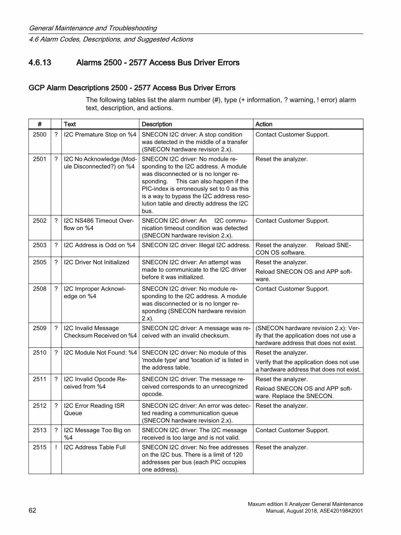
4.6.13 Alarms 2500 - 2577 Access Bus Driver Errors
GCP Alarm Descriptions 2500 - 2577 Access Bus Driver ErrorsThe following tables list the alarm number (#), type (+ information, ? warning, ! error) alarm text, description, and actions.
# Text Description Action2500 ? I2C Premature Stop on %4 SNECON I2C driver: A stop condition
was detected in the middle of a transfer (SNECON hardware revision 2.x).
Contact Customer Support.
2501 ? I2C No Acknowledge (Mod‐ule Disconnected?) on %4
SNECON I2C driver: No module re‐sponding to the I2C address. A module was disconnected or is no longer re‐sponding. This can also happen if the PIC-index is erroneously set to 0 as this is a way to bypass the I2C address reso‐lution table and directly address the I2C bus.
Reset the analyzer.
2502 ? I2C NS486 Timeout Over‐flow on %4
SNECON I2C driver: An I2C commu‐nication timeout condition was detected (SNECON hardware revision 2.x).
Contact Customer Support.
2503 ? I2C Address is Odd on %4 SNECON I2C driver: Illegal I2C address. Reset the analyzer. Reload SNE‐CON OS software.
2505 ? I2C Driver Not Initialized SNECON I2C driver: An attempt was made to communicate to the I2C driver before it was initialized.
Reset the analyzer. Reload SNECON OS and APP soft‐ware.
2508 ? I2C Improper Acknowl‐edge on %4
SNECON I2C driver: No module re‐sponding to the I2C address. A module was disconnected or is no longer re‐sponding (SNECON hardware revision 2.x).
Contact Customer Support.
2509 ? I2C Invalid Message Checksum Received on %4
SNECON I2C driver: A message was re‐ceived with an invalid checksum.
(SNECON hardware revision 2.x): Ver‐ify that the application does not use a hardware address that does not exist.
2510 ? I2C Module Not Found: %4 SNECON I2C driver: No module of this 'module type' and 'location id' is listed in the address table.
Reset the analyzer. Verify that the application does not use a hardware address that does not exist.
2511 ? I2C Invalid Opcode Re‐ceived from %4
SNECON I2C driver: The message re‐ceived corresponds to an unrecognized opcode.
Reset the analyzer. Reload SNECON OS and APP soft‐ware. Replace the SNECON.
2512 ? I2C Error Reading ISR Queue
SNECON I2C driver: An error was detec‐ted reading a communication queue (SNECON hardware revision 2.x).
Reset the analyzer.
2513 ? I2C Message Too Big on %4
SNECON I2C driver: The I2C message received is too large and is not valid.
Contact Customer Support.
2515 ! I2C Address Table Full SNECON I2C driver: No free addresses on the I2C bus. There is a limit of 120 addresses per bus (each PIC occupies one address).
Reset the analyzer.
General Maintenance and Troubleshooting4.6 Alarm Codes, Descriptions, and Suggested Actions
Maxum edition II Analyzer General Maintenance62 Manual, August 2018, A5E42019842001
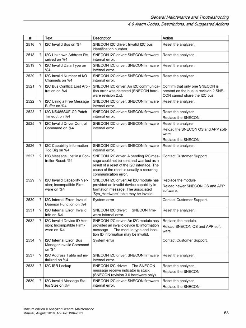
# Text Description Action2516 ? I2C Invalid Bus on %4 SNECON I2C driver: Invalid I2C bus
identification number.Reset the analyzer.
2518 ? I2C Unknown Address Re‐ceived on %4
SNECON I2C driver: SNECON firmware internal error.
Reset the analyzer.
2519 ? I2C Invalid Data Type on %4
SNECON I2C driver: SNECON firmware internal error.
Reset the analyzer.
2520 ? I2C Invalid Number of I/O Channels on %4
SNECON I2C driver: SNECON firmware internal error.
Reset the analyzer.
2521 ? I2C Bus Conflict; Lost Arbi‐tration on %4
SNECON I2C driver: An I2C communica‐tion error was detected (SNECON hard‐ware revision 2.x).
Confirm that only one SNECON is present on the bus; a revision 2 SNE‐CON cannot share the I2C bus.
2522 ? I2C Using a Free Message Buffer on %4
SNECON I2C driver: SNECON firmware internal error.
Reset the analyzer.
2523 ? I2C NS486SXF-C0 Patch Timeout on %4
SNECON I2C driver: SNECON firmware internal error.
Reset the analyzer. Replace the SNECON.
2525 ? I2C Invalid Driver Control Command on %4
SNECON I2C driver: SNECON firmware internal error.
Reset the analyzer Reload the SNECON OS and APP soft‐ware. Replace the SNECON.
2526 ? I2C Capability Information Too Big on %4
SNECON I2C driver: SNECON firmware internal error.
Reset the analyzer.
2527 ? I2C Message Lost in a Con‐troller Reset: %4
SNECON I2C driver: A pending I2C mes‐sage could not be sent and was lost as a result of a reset of the I2C interface. The cause of the reset is usually a recurring communication error.
Contact Customer Support.
2529 ? I2C Invalid Capability Ver‐sion; Incompatible Firm‐ware on %4
SNECON I2C driver: An I2C module has provided an invalid device capability in‐formation message. The associated 'Sys_Hardware' table may be invalid.
Replace the module Reload newer SNECON OS and APP software.
2530 ? I2C Internal Error; Invalid Daemon Function on %4
System error Contact Customer Support.
2531 ? I2C Internal Error; Invalid Info on %4
SNECON I2C driver: SNECON firm‐ware internal error.
Reset the analyzer.
2532 ? I2C Invalid Device ID Ver‐sion; Incompatible Firm‐ware on %4
SNECON I2C driver: An I2C module has provided an invalid device ID information message. The module type and loca‐tion ID information may be invalid.
Replace the module. Reload SNECON OS and APP soft‐ware.
2534 ? I2C Internal Error; Bus Manager Invalid Command on %4
System error Contact Customer Support.
2537 ? I2C Address Table not ini‐tialized on %4
SNECON I2C driver: SNECON firmware internal error.
Reset the analyzer.
2538 ? I2C ISR Lockup SNECON I2C driver: The SNECON message receive indicator is stuck (SNECON revision 3.0 hardware only).
Reset the analyzer. Replace the SNECON.
2539 ? I2C Invalid Message Sta‐tus Size on %4
SNECON I2C driver: SNECON firmware internal error.
Reset the analyzer. Replace the SNECON.
General Maintenance and Troubleshooting4.6 Alarm Codes, Descriptions, and Suggested Actions
Maxum edition II Analyzer General MaintenanceManual, August 2018, A5E42019842001 63

# Text Description Action2540 ? I2C Message Too Short on
%4SNECON I2C driver: An I2C message received by the SNECON is too short to be valid.
Contact Customer Support.
2541 + I2C FPGA Queue Full on %4
SNECON I2C driver: SNECON firmware internal error (SNECON revision 3.0 hardware only).
Reset the analyzer. Replace the SNECON.
2542 ? I2C FPGA Write Before End on %4
SNECON I2C driver: SNECON firmware internal error (SNECON revision 3.0 hardware only).
Reset the analyzer. Replace the SNECON.
2543 ? I2C FPGA Write After End on %4
SNECON I2C driver: SNECON firmware internal error (SNECON revision 3.0 hardware only).
Reset the analyzer. Replace the SNECON.
2544 ? I2C FPGA Message Too Short on %4
SNECON I2C driver: SNECON firmware internal error (SNECON revision 3.0 hardware only).
Reset the analyzer. Replace the SNECON.
2545 ? I2C FPGA Invalid Check‐sum on %4
SNECON I2C driver: SNECON on-board communication error. Known to hap‐pen very infrequently with SNECON I2C FPGA rev 23 or lower (SNECON revision 3.0 hardware only).
Ignore the alarm. If occurring frequent‐ly, replace the SNECON.
2546 ? I2C FPGA Invalid Size on %4
SNECON I2C driver: SNECON firmware internal error (SNECON revision 3.0 hardware only).
Reset the analyzer. Reload the SNECON OS software.Replace the SNECON.
2547 ! I2C Heartbeat Timeout Ex‐pired; Resetting Controller
SNECON I2C driver: A SNECON PIC was not responding and was reset (SNE‐CON revision 3.0 hardware only).
Reset the analyzer. Reload the SNECON OS software.Replace the SNECON.
2549 ? I2C Heartbeat Counter Mis‐match on %4
SNECON I2C driver: One or more mes‐sages were lost on the on-board commu‐nication (SNECON rev 3.0 hardware on‐ly).
Reset the analyzer. Reload the SNECON OS software.Replace the SNECON.
2550 ? I2C Invalid Message Sta‐tus on %4
SNECON I2C driver: SNECON firmware internal error (SNECON revision 3.0 hardware only).
Reset the analyzer. Reload the SNECON OS software.Replace the SNECON.
2551 ? I2C Internal Error; Invalid Block Structure ID on %4
SNECON I2C driver: SNECON firmware internal error (SNECON revision 3.0 hardware only).
Reset the analyzer. Reload the SNECON OS software.Replace the SNECON.
2552 ? I2C Internal Error; Invalid Block Offset on %4
SNECON I2C driver: SNECON firmware internal error (SNECON revision 3.0 hardware only).
Reset the analyzer. Reload the SNECON OS software.Replace the SNECON.
2553 ? I2C Internal Error; Invalid Block ID on %4
SNECON I2C driver: SNECON firmware internal error (SNECON revision 3.0 hardware only).
Reset the analyzer. Reload the SNECON OS software.Replace the SNECON.
2554 ? I2C Internal Error; New Block Offset Non-Zero on %4
SNECON I2C driver: SNECON firmware internal error (SNECON revision 3.0 hardware only).
Reset the analyzer. Reload the SNECON OS software.Replace the SNECON.
General Maintenance and Troubleshooting4.6 Alarm Codes, Descriptions, and Suggested Actions
Maxum edition II Analyzer General Maintenance64 Manual, August 2018, A5E42019842001

# Text Description Action2555 ? I2C Internal Error; Block
Table fullSNECON I2C driver: SNECON firmware internal error (SNECON revision 3.0 hardware only).
Reset the analyzer. Reload the SNECON OS software.Replace the SNECON.
2556 ? I2C Not Enough Memory SNECON I2C driver: SNECON firmware internal error.
Reset the analyzer. Reload the SNECON OS software.Replace the SNECON.
2557 ? I2C Internal Error; Block Too Large on %4
SNECON I2C driver: SNECON firmware internal error (SNECON revision 3.0 hardware only).
Reset the analyzer. Reload the SNECON OS software.Replace the SNECON.
2558 ? I2C Internal Error; Block Not Found on %4
SNECON I2C driver: SNECON firmware internal error (SNECON revision 3.0 hardware only).
Reset the analyzer. Reload the SNECON OS software.Replace the SNECON.
2559 ? I2C Internal Error; Invalid Block Size on %4
SNECON I2C driver: SNECON firmware internal error (SNECON revision 3.0 hardware only).
Reset the analyzer. Reload the SNECON OS software.Replace the SNECON.
2560 ! I2C Driver OS and Applica‐tion version mismatch
SNECON I2C driver: The version num‐ber of the SNECON OS is incompatible with the SNECON APP version.
Reset the analyzer. Reload the SNECON OS software.Replace the SNECON.
2562 ? I2C Internal Error; Bad state on %4
SNECON I2C driver: SNECON firmware internal error.
Reset the analyzer. Reload the SNECON OS software.Replace the SNECON.
2563 ! I2C FPGA bad version SNECON I2C driver: The SNECON I2C FPGA is incompatible or broken.
Reload the SNECON OS with the new‐est version. Replace the SNECON.
2564 ! I2C Temperature Block Version Invalid
SNECON I2C driver: The temperature controller PID parameter data block sup‐plied by the SYSCON is incompatible.
Reload the SNECON OS and APP soft‐ware to the corresponding SYSCON version.
2565 ? I2C Opcode not expected in current state on %4
SNECON I2C driver: Unexpected I2C message opcode received by the SNE‐CON from a module.I2C communication error.
Contact Customer Support.
2566 ! I2C Modules were reset fol‐lowing multiple errors
SNECON I2C driver: A fatal error or mul‐tiple consecutive retries have forced the I2C controller to reset.
Contact Customer Support.
2567 ! I2C Header Index Mis‐match; Message Lost
System error Contact Customer Support.
2568 ? I2C Internal Error; Invalid Block Index on %4
SNECON I2C driver: SNECON firmware internal error (SNECON revision 3.0 hardware only).
Reset the analyzer. Reload the SNECON OS software.
2569 ? I2C FPGA Queue Full on %4
SNECON I2C driver: The SNECON I2C FPGA queue is full, the PIC is no longer processing I2C messages.
Reset the analyzer. Reload the SNECON OS software.
2570 ? I2C FPGA Packet Too Big on %4
SNECON I2C driver: SNECON firmware internal error (SNECON revision 3.0 hardware only).
Reset the analyzer. Reload the SNECON OS software.Replace the SNECON.
General Maintenance and Troubleshooting4.6 Alarm Codes, Descriptions, and Suggested Actions
Maxum edition II Analyzer General MaintenanceManual, August 2018, A5E42019842001 65

# Text Description Action2571 ? I2C FPGA Recovery Failed
on %4SNECON I2C driver: SNECON firmware internal error (SNECON revision 3.0 hardware only).
Reset the analyzer. Reload the SNECON OS software.Replace the SNECON.
2572 ? I2C FPGA Read in pro‐gress not set after header on %4
SNECON I2C driver: SNECON firmware internal error (SNECON revision 3.0 hardware only).
Reset the analyzer. Reload the SNECON OS software.Replace the SNECON.
2573 ? I2C Not enough memory in ISR on %4
SNECON I2C driver: SNECON firmware internal error (SNECON revision 3.0 hardware only).
Reset the analyzer. Reload the SNECON OS software.Replace the SNECON.
2574 ! I2C PIC Reset Detected on %4
SNECON I2C driver: A problem was de‐tected by a SNECON PIC and it went through a reset. Can also be caused by an I2C communication error.
If occurring frequently, replace the SNE‐CON.
2575 ? I2C General AO error on %4
SNECON I2C driver: A channel specific error was detected while an AO com‐mand was processed (Example AO out of range) . A more specific alarm will be reported by the module on the next poll.
Provides the channel information for an alarm reported on the same module.
2576 ? I2C General DO error on %4
SNECON I2C driver: A channel specific error was detected while an DO com‐mand was processed (Example DO out of range) . A more specific alarm will be reported by the module on the next poll.
Provides the channel information for an alarm reported on the same module.
2577 ? I2C bus configuration changed
The configuration between internal I2C (5V I2C) and external, SSSI (10V I2C) was changed. The configuration change is ignored until the next reset.
If the configuration was changed inten‐tionally, simply reset the device. Other‐wise, verify that the cable in J3 and J13 on SNECON V4 or J1 and J3 on the SIB are properly inserted.
General Maintenance and Troubleshooting4.6 Alarm Codes, Descriptions, and Suggested Actions
Maxum edition II Analyzer General Maintenance66 Manual, August 2018, A5E42019842001
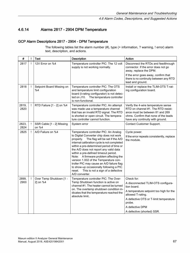
4.6.14 Alarms 2817 - 2904 DPM Temperature
GCP Alarm Descriptions 2817 - 2904 - DPM TemperatureThe following tables list the alarm number (#), type (+ information, ? warning, ! error) alarm text, description, and actions.
# ! Text Description Action2817 ! 12V Error on %4 Temperature controller PIC: The 12 volt
supply is not working normally.Disconnect the RTDs and feedthrough connector. If the error does not go away, replace the DPM. If the error goes away, confirm that there is no continuity between any RTD lead and ground.
2818 ! Setpoint Board Missing on %4
Temperature controller PIC: The OTS and temperature limit configuration board (t-rating configurator) is not detec‐ted on J10. The temperature controller is non-functional.
Install or replace the TLIM-OTS T-rat‐ing configuration board.
2819, 2820
! RTD Failure [1 - 2] on %4 Temperature controller PIC: An attempt was made use a temperature channel that has an invalid RTD signal. The RTD is shorted or open circuit. The tempera‐ture controller cannot function.
Verify the 4-wire temperature sense RTD on channel #1. The RTD resist‐ance must be between 81 and 269 ohms. Confirm that none of the leads have any continuity with ground.
2823, 2824
! SSR Cable [1 - 2] Missing on %4
System error Contact Customer Support.
2825 ! A/D Failure on %4 Temperature controller PIC: An Analog to Digital Converter chip does not work properly. The flag will be set if the A/D internal calibration cycle is not completed within a pre-determined period of time or the A/D does not report any valid data within a pre-defined timeout period. Note: A firmware problem affecting the version 1.002 of the Temperature con‐troller PIC may cause an A/D failure flag to show-up occasionally following a PIC reset. This is not a sign of a defective A/D converter.
Cycle power. If the error repeats consistently, replace the module.
2899, 2900
! Over Temp Shutdown [1 - 2] on %4
Temperature controller PIC: The Over-Temp Shutdown function is active on channel #1. The heater cannot be turned on. The overtemp shutdown condition in‐dicates that the temperature reached the absolute limit..
Check for: A disconnected TLIM-OTS configura‐tion board. A temperature setpoint too high for the allowed T-rating. A defective OTS or T-limit temperature probe. A defective DPM A defective (shorted) SSR.
General Maintenance and Troubleshooting4.6 Alarm Codes, Descriptions, and Suggested Actions
Maxum edition II Analyzer General MaintenanceManual, August 2018, A5E42019842001 67
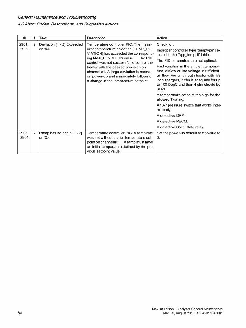
# ! Text Description Action2901, 2902
? Deviation [1 - 2] Exceeded on %4
Temperature controller PIC: The meas‐ured temperature deviation (TEMP_DE‐VIATION) has exceeded the correspond‐ing MAX_DEVIATION value. The PID control was not successful to control the heater with the desired precision on channel #1. A large deviation is normal on power-up and immediately following a change in the temperature setpoint.
Check for:Improper controller type 'temptype' se‐lected in the 'App_tempctl' table. The PID parameters are not optimal. Fast variation in the ambient tempera‐ture, airflow or line voltage.Insufficient air flow. For an air bath heater with 1/8 inch spargers, 3 cfm is adequate for up to 100 DegC and then 4 cfm should be used. A temperature setpoint too high for the allowed T-rating. An Air pressure switch that works inter‐mittently. A defective DPM. A defective PECM. A defective Solid State relay.
2903, 2904
? Ramp has no origin [1 - 2] on %4
Temperature controller PIC: A ramp rate was set without a prior temperature set‐point on channel #1. A ramp must have an initial temperature defined by the pre‐vious setpoint value.
Set the power-up default ramp value to 0.
General Maintenance and Troubleshooting4.6 Alarm Codes, Descriptions, and Suggested Actions
Maxum edition II Analyzer General Maintenance68 Manual, August 2018, A5E42019842001
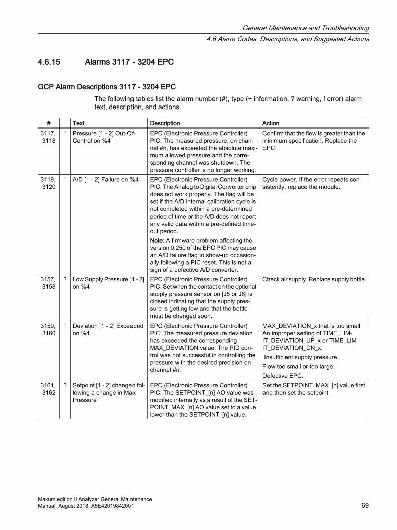
4.6.15 Alarms 3117 - 3204 EPC
GCP Alarm Descriptions 3117 - 3204 EPCThe following tables list the alarm number (#), type (+ information, ? warning, ! error) alarm text, description, and actions.
# Text Description Action3117, 3118
! Pressure [1 - 2] Out-Of-Control on %4
EPC (Electronic Pressure Controller) PIC: The measured pressure, on chan‐nel #n, has exceeded the absolute maxi‐mum allowed pressure and the corre‐sponding channel was shutdown. The pressure controller is no longer working.
Confirm that the flow is greater than the minimum specification. Replace the EPC.
3119, 3120
! A/D [1 - 2] Failure on %4 EPC (Electronic Pressure Controller) PIC: The Analog to Digital Converter chip does not work properly. The flag will be set if the A/D internal calibration cycle is not completed within a pre-determined period of time or the A/D does not report any valid data within a pre-defined time‐out period. Note: A firmware problem affecting the version 0.250 of the EPC PIC may cause an A/D failure flag to show-up occasion‐ally following a PIC reset. This is not a sign of a defective A/D converter.
Cycle power. If the error repeats con‐sistently, replace the module.
3157, 3158
? Low Supply Pressure [1 - 2] on %4
EPC (Electronic Pressure Controller) PIC: Set when the contact on the optional supply pressure sensor on [J5 or J6] is closed indicating that the supply pres‐sure is getting low and that the bottle must be changed soon.
Check air supply. Replace supply bottle.
3159, 3160
! Deviation [1 - 2] Exceeded on %4
EPC (Electronic Pressure Controller) PIC: The measured pressure deviation has exceeded the corresponding MAX_DEVIATION value. The PID con‐trol was not successful in controlling the pressure with the desired precision on channel #n.
MAX_DEVIATION_x that is too small. An improper setting of TIME_LIM‐IT_DEVIATION_UP_x or TIME_LIM‐IT_DEVIATION_DN_x. Insufficient supply pressure. Flow too small or too large. Defective EPC.
3161, 3162
? Setpoint [1 - 2] changed fol‐lowing a change in Max Pressure
EPC (Electronic Pressure Controller) PIC: The SETPOINT_[n] AO value was modified internally as a result of the SET‐POINT_MAX_[n] AO value set to a value lower than the SETPOINT_[n] value.
Set the SETPOINT_MAX_[n] value first and then set the setpoint.
General Maintenance and Troubleshooting4.6 Alarm Codes, Descriptions, and Suggested Actions
Maxum edition II Analyzer General MaintenanceManual, August 2018, A5E42019842001 69
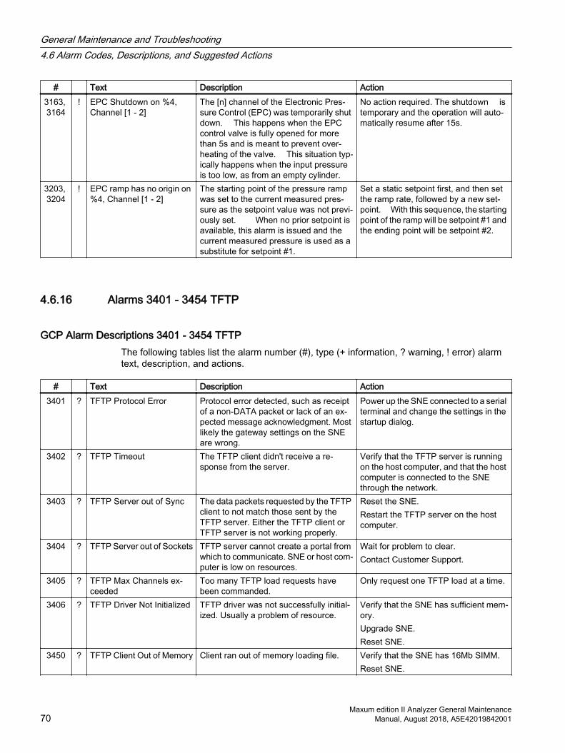
# Text Description Action3163, 3164
! EPC Shutdown on %4, Channel [1 - 2]
The [n] channel of the Electronic Pres‐sure Control (EPC) was temporarily shut down. This happens when the EPC control valve is fully opened for more than 5s and is meant to prevent over‐heating of the valve. This situation typ‐ically happens when the input pressure is too low, as from an empty cylinder.
No action required. The shutdown is temporary and the operation will auto‐matically resume after 15s.
3203, 3204
! EPC ramp has no origin on %4, Channel [1 - 2]
The starting point of the pressure ramp was set to the current measured pres‐sure as the setpoint value was not previ‐ously set. When no prior setpoint is available, this alarm is issued and the current measured pressure is used as a substitute for setpoint #1.
Set a static setpoint first, and then set the ramp rate, followed by a new set‐point. With this sequence, the starting point of the ramp will be setpoint #1 and the ending point will be setpoint #2.
4.6.16 Alarms 3401 - 3454 TFTP
GCP Alarm Descriptions 3401 - 3454 TFTPThe following tables list the alarm number (#), type (+ information, ? warning, ! error) alarm text, description, and actions.
# Text Description Action3401 ? TFTP Protocol Error Protocol error detected, such as receipt
of a non-DATA packet or lack of an ex‐pected message acknowledgment. Most likely the gateway settings on the SNE are wrong.
Power up the SNE connected to a serial terminal and change the settings in the startup dialog.
3402 ? TFTP Timeout The TFTP client didn't receive a re‐sponse from the server.
Verify that the TFTP server is running on the host computer, and that the host computer is connected to the SNE through the network.
3403 ? TFTP Server out of Sync The data packets requested by the TFTP client to not match those sent by the TFTP server. Either the TFTP client or TFTP server is not working properly.
Reset the SNE. Restart the TFTP server on the host computer.
3404 ? TFTP Server out of Sockets TFTP server cannot create a portal from which to communicate. SNE or host com‐puter is low on resources.
Wait for problem to clear. Contact Customer Support.
3405 ? TFTP Max Channels ex‐ceeded
Too many TFTP load requests have been commanded.
Only request one TFTP load at a time.
3406 ? TFTP Driver Not Initialized TFTP driver was not successfully initial‐ized. Usually a problem of resource.
Verify that the SNE has sufficient mem‐ory. Upgrade SNE. Reset SNE.
3450 ? TFTP Client Out of Memory Client ran out of memory loading file. Verify that the SNE has 16Mb SIMM.Reset SNE.
General Maintenance and Troubleshooting4.6 Alarm Codes, Descriptions, and Suggested Actions
Maxum edition II Analyzer General Maintenance70 Manual, August 2018, A5E42019842001
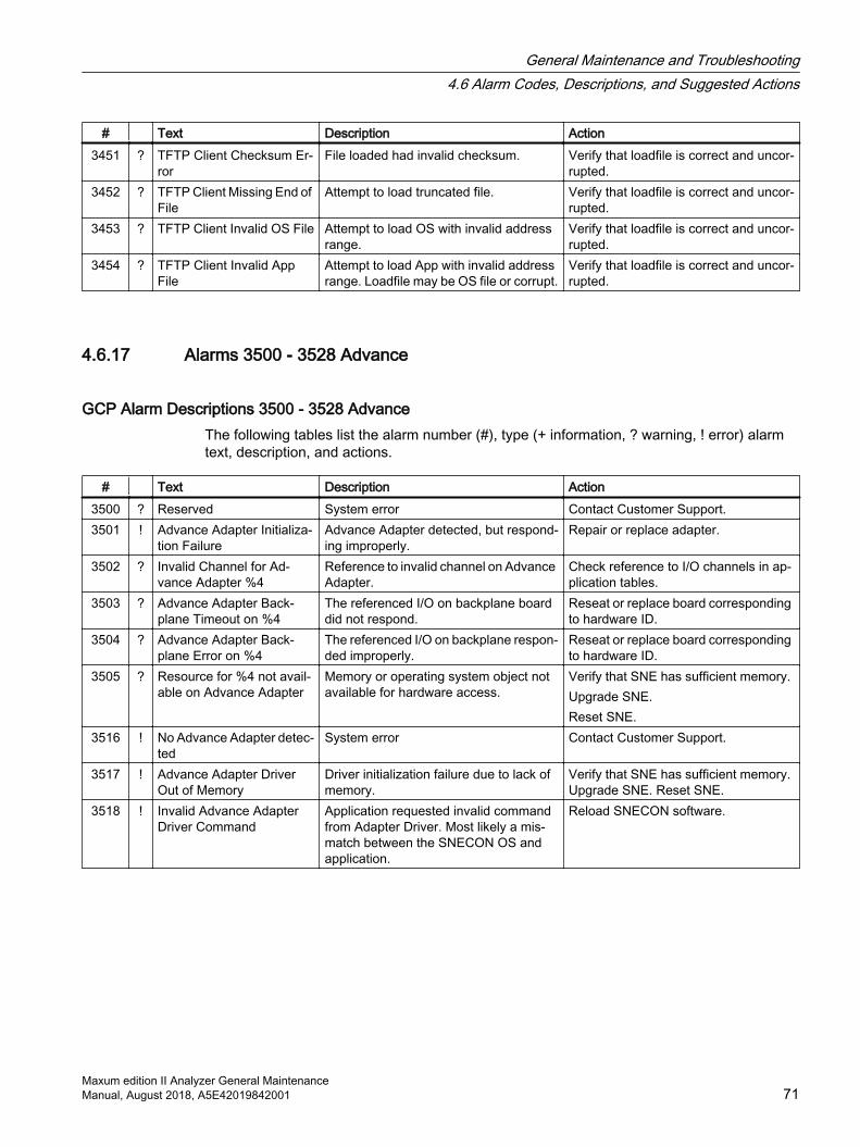
# Text Description Action3451 ? TFTP Client Checksum Er‐
rorFile loaded had invalid checksum. Verify that loadfile is correct and uncor‐
rupted.3452 ? TFTP Client Missing End of
FileAttempt to load truncated file. Verify that loadfile is correct and uncor‐
rupted.3453 ? TFTP Client Invalid OS File Attempt to load OS with invalid address
range.Verify that loadfile is correct and uncor‐rupted.
3454 ? TFTP Client Invalid App File
Attempt to load App with invalid address range. Loadfile may be OS file or corrupt.
Verify that loadfile is correct and uncor‐rupted.
4.6.17 Alarms 3500 - 3528 Advance
GCP Alarm Descriptions 3500 - 3528 AdvanceThe following tables list the alarm number (#), type (+ information, ? warning, ! error) alarm text, description, and actions.
# Text Description Action3500 ? Reserved System error Contact Customer Support.3501 ! Advance Adapter Initializa‐
tion FailureAdvance Adapter detected, but respond‐ing improperly.
Repair or replace adapter.
3502 ? Invalid Channel for Ad‐vance Adapter %4
Reference to invalid channel on Advance Adapter.
Check reference to I/O channels in ap‐plication tables.
3503 ? Advance Adapter Back‐plane Timeout on %4
The referenced I/O on backplane board did not respond.
Reseat or replace board corresponding to hardware ID.
3504 ? Advance Adapter Back‐plane Error on %4
The referenced I/O on backplane respon‐ded improperly.
Reseat or replace board corresponding to hardware ID.
3505 ? Resource for %4 not avail‐able on Advance Adapter
Memory or operating system object not available for hardware access.
Verify that SNE has sufficient memory. Upgrade SNE. Reset SNE.
3516 ! No Advance Adapter detec‐ted
System error Contact Customer Support.
3517 ! Advance Adapter Driver Out of Memory
Driver initialization failure due to lack of memory.
Verify that SNE has sufficient memory. Upgrade SNE. Reset SNE.
3518 ! Invalid Advance Adapter Driver Command
Application requested invalid command from Adapter Driver. Most likely a mis‐match between the SNECON OS and application.
Reload SNECON software.
General Maintenance and Troubleshooting4.6 Alarm Codes, Descriptions, and Suggested Actions
Maxum edition II Analyzer General MaintenanceManual, August 2018, A5E42019842001 71
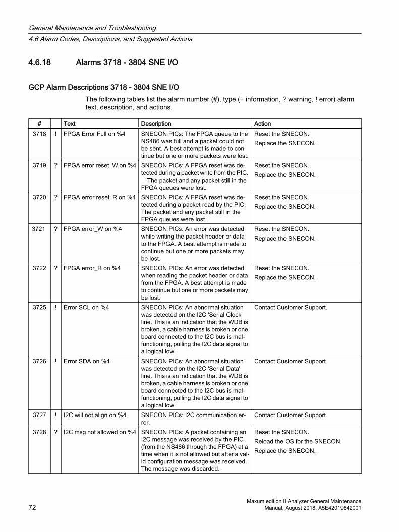
4.6.18 Alarms 3718 - 3804 SNE I/O
GCP Alarm Descriptions 3718 - 3804 SNE I/OThe following tables list the alarm number (#), type (+ information, ? warning, ! error) alarm text, description, and actions.
# Text Description Action3718 ! FPGA Error Full on %4 SNECON PICs: The FPGA queue to the
NS486 was full and a packet could not be sent. A best attempt is made to con‐tinue but one or more packets were lost.
Reset the SNECON. Replace the SNECON.
3719 ? FPGA error reset_W on %4 SNECON PICs: A FPGA reset was de‐tected during a packet write from the PIC. The packet and any packet still in the FPGA queues were lost.
Reset the SNECON. Replace the SNECON.
3720 ? FPGA error reset_R on %4 SNECON PICs: A FPGA reset was de‐tected during a packet read by the PIC. The packet and any packet still in the FPGA queues were lost.
Reset the SNECON. Replace the SNECON.
3721 ? FPGA error_W on %4 SNECON PICs: An error was detected while writing the packet header or data to the FPGA. A best attempt is made to continue but one or more packets may be lost.
Reset the SNECON. Replace the SNECON.
3722 ? FPGA error_R on %4 SNECON PICs: An error was detected when reading the packet header or data from the FPGA. A best attempt is made to continue but one or more packets may be lost.
Reset the SNECON. Replace the SNECON.
3725 ! Error SCL on %4 SNECON PICs: An abnormal situation was detected on the I2C 'Serial Clock' line. This is an indication that the WDB is broken, a cable harness is broken or one board connected to the I2C bus is mal‐functioning, pulling the I2C data signal to a logical low.
Contact Customer Support.
3726 ! Error SDA on %4 SNECON PICs: An abnormal situation was detected on the I2C 'Serial Data' line. This is an indication that the WDB is broken, a cable harness is broken or one board connected to the I2C bus is mal‐functioning, pulling the I2C data signal to a logical low.
Contact Customer Support.
3727 ! I2C will not align on %4 SNECON PICs: I2C communication er‐ror.
Contact Customer Support.
3728 ? I2C msg not allowed on %4 SNECON PICs: A packet containing an I2C message was received by the PIC (from the NS486 through the FPGA) at a time when it is not allowed but after a val‐id configuration message was received. The message was discarded.
Reset the SNECON.Reload the OS for the SNECON. Replace the SNECON.
General Maintenance and Troubleshooting4.6 Alarm Codes, Descriptions, and Suggested Actions
Maxum edition II Analyzer General Maintenance72 Manual, August 2018, A5E42019842001
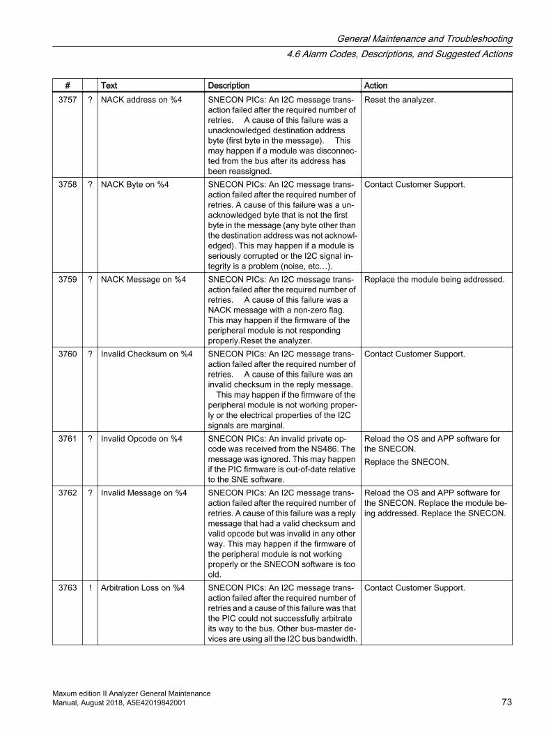
# Text Description Action3757 ? NACK address on %4 SNECON PICs: An I2C message trans‐
action failed after the required number of retries. A cause of this failure was a unacknowledged destination address byte (first byte in the message). This may happen if a module was disconnec‐ted from the bus after its address has been reassigned.
Reset the analyzer.
3758 ? NACK Byte on %4 SNECON PICs: An I2C message trans‐action failed after the required number of retries. A cause of this failure was a un‐acknowledged byte that is not the first byte in the message (any byte other than the destination address was not acknowl‐edged). This may happen if a module is seriously corrupted or the I2C signal in‐tegrity is a problem (noise, etc…).
Contact Customer Support.
3759 ? NACK Message on %4 SNECON PICs: An I2C message trans‐action failed after the required number of retries. A cause of this failure was a NACK message with a non-zero flag. This may happen if the firmware of the peripheral module is not responding properly.Reset the analyzer.
Replace the module being addressed.
3760 ? Invalid Checksum on %4 SNECON PICs: An I2C message trans‐action failed after the required number of retries. A cause of this failure was an invalid checksum in the reply message. This may happen if the firmware of the peripheral module is not working proper‐ly or the electrical properties of the I2C signals are marginal.
Contact Customer Support.
3761 ? Invalid Opcode on %4 SNECON PICs: An invalid private op‐code was received from the NS486. The message was ignored. This may happen if the PIC firmware is out-of-date relative to the SNE software.
Reload the OS and APP software for the SNECON. Replace the SNECON.
3762 ? Invalid Message on %4 SNECON PICs: An I2C message trans‐action failed after the required number of retries. A cause of this failure was a reply message that had a valid checksum and valid opcode but was invalid in any other way. This may happen if the firmware of the peripheral module is not working properly or the SNECON software is too old.
Reload the OS and APP software for the SNECON. Replace the module be‐ing addressed. Replace the SNECON.
3763 ! Arbitration Loss on %4 SNECON PICs: An I2C message trans‐action failed after the required number of retries and a cause of this failure was that the PIC could not successfully arbitrate its way to the bus. Other bus-master de‐vices are using all the I2C bus bandwidth.
Contact Customer Support.
General Maintenance and Troubleshooting4.6 Alarm Codes, Descriptions, and Suggested Actions
Maxum edition II Analyzer General MaintenanceManual, August 2018, A5E42019842001 73

# Text Description Action3764 ? Timeout SCL on %4 SNECON PICs: An I2C message trans‐
action failed because the I2C clock was stretched beyond the allowed timeout pe‐riod specified in the configuration. A mod‐ule may be malfunctioning.
Contact Customer Support.
3765 ? Timeout SDA on %4 SNECON PICs: An I2C message trans‐action failed because the I2C data line was held beyond the allowed timeout pe‐riod specified in the configuration. A mod‐ule may be malfunctioning.
Contact Customer Support.
3766 ? Bus Not Sync on %4 SNECON PICs: The master-mode oper‐ation generated a start condition that was not detected by the FPGA.
Reset the SNECON. Replace the SNE‐CON.
3767 ? Timeout Buffer on %4 SNECON PICs: A master-mode mes‐sage has not been processed within a timeout period. This is a broad alarm with multiple possible causes. The PIC will discard the message and attempt to re‐cover.
Contact Customer Support.
3768 ? Invalid Handle on %4 SNECON PICs: The received header handle was not sequential. One or more I2C messages were lost.
Reset the SNECON.Replace the SNECON.
3769 ? High I2C traffic on %4 The amount of traffic on the I2C bus has exceeded a configurable threshold. A heavy traffic may delay the I/O activity which ultimately can affect the operation (accuracy, repeatability) of the analyzer.
Check the methods to ensure that the I/O activity is distributed in time and not all at the same exact cycle time (Detec‐tor balance event, valve events, tem‐perature and pressure setpoint, etc).
3797 + Invalid Checksum Slave on %4
SNECON PICs: An unsolicited I2C mes‐sage was received with a bad checksum. The message was discarded and it is ex‐pected that the master will retry the mes‐sage. This is a communication error that can be ignored if not frequent.
Reset the SNECON. Replace the SNECON.
3798 + Invalid Message Slave on %4
SNECON PICs: An unsolicited I2C mes‐sage was received with an invalid mes‐sage size, invalid opcode or invalid data. The message was discarded. There may be a firmware version conflict.
Reload the OS and APP software to all SNECONs.
3799 ? Invalid Status Summary on %4
SNECON PICs: A packet was received by the PIC from the NS486 and the pack‐et had an undefined bit set in the Sta‐tus_summary field of the packet. The packet was processed normally.
Reload the OS and APP software for the SNECON. Replace the SNECON.
3800 ? Module Not Ready on %4 SNECON PICs: An I2C message trans‐action failed after the required number of retries and the cause of the failure was a series of consecutive message NACKs, all with a 0 flag. This may happen if the firmware of the peripheral module is not responding properly.
Reload the OS and APP software for the SNECON. Replace the module being addressed. Replace the SNECON.
General Maintenance and Troubleshooting4.6 Alarm Codes, Descriptions, and Suggested Actions
Maxum edition II Analyzer General Maintenance74 Manual, August 2018, A5E42019842001
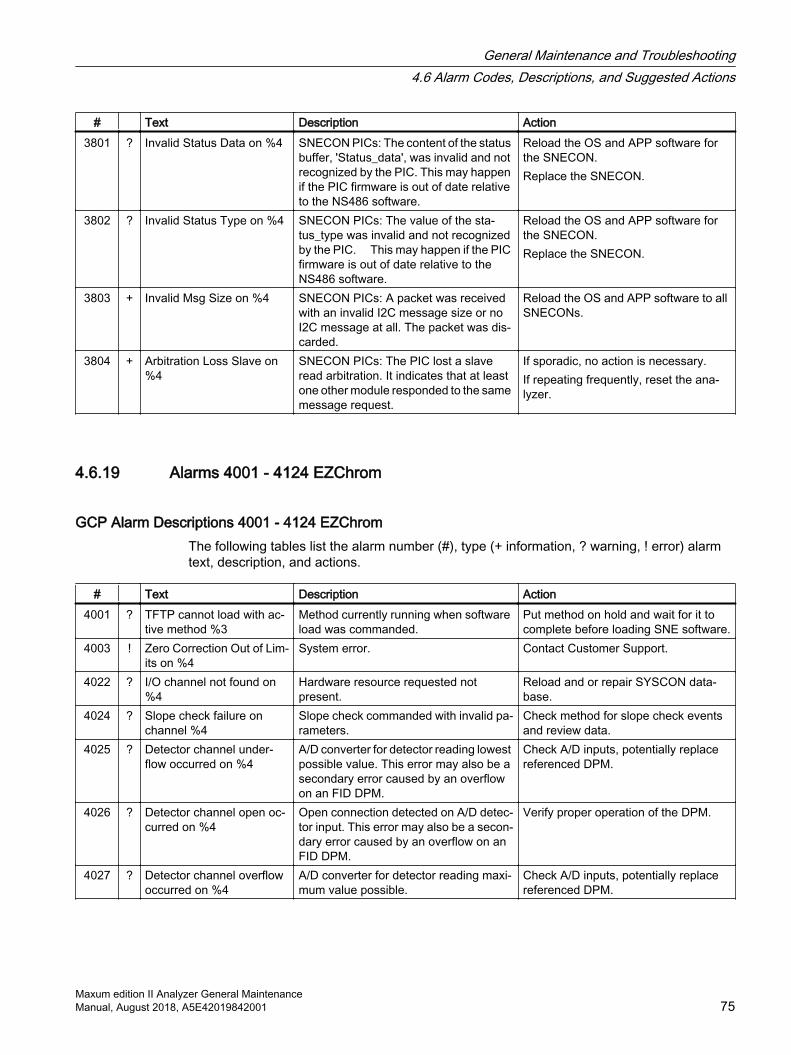
# Text Description Action3801 ? Invalid Status Data on %4 SNECON PICs: The content of the status
buffer, 'Status_data', was invalid and not recognized by the PIC. This may happen if the PIC firmware is out of date relative to the NS486 software.
Reload the OS and APP software for the SNECON. Replace the SNECON.
3802 ? Invalid Status Type on %4 SNECON PICs: The value of the sta‐tus_type was invalid and not recognized by the PIC. This may happen if the PIC firmware is out of date relative to the NS486 software.
Reload the OS and APP software for the SNECON. Replace the SNECON.
3803 + Invalid Msg Size on %4 SNECON PICs: A packet was received with an invalid I2C message size or no I2C message at all. The packet was dis‐carded.
Reload the OS and APP software to all SNECONs.
3804 + Arbitration Loss Slave on %4
SNECON PICs: The PIC lost a slave read arbitration. It indicates that at least one other module responded to the same message request.
If sporadic, no action is necessary. If repeating frequently, reset the ana‐lyzer.
4.6.19 Alarms 4001 - 4124 EZChrom
GCP Alarm Descriptions 4001 - 4124 EZChromThe following tables list the alarm number (#), type (+ information, ? warning, ! error) alarm text, description, and actions.
# Text Description Action4001 ? TFTP cannot load with ac‐
tive method %3Method currently running when software load was commanded.
Put method on hold and wait for it to complete before loading SNE software.
4003 ! Zero Correction Out of Lim‐its on %4
System error. Contact Customer Support.
4022 ? I/O channel not found on %4
Hardware resource requested not present.
Reload and or repair SYSCON data‐base.
4024 ? Slope check failure on channel %4
Slope check commanded with invalid pa‐rameters.
Check method for slope check events and review data.
4025 ? Detector channel under‐flow occurred on %4
A/D converter for detector reading lowest possible value. This error may also be a secondary error caused by an overflow on an FID DPM.
Check A/D inputs, potentially replace referenced DPM.
4026 ? Detector channel open oc‐curred on %4
Open connection detected on A/D detec‐tor input. This error may also be a secon‐dary error caused by an overflow on an FID DPM.
Verify proper operation of the DPM.
4027 ? Detector channel overflow occurred on %4
A/D converter for detector reading maxi‐mum value possible.
Check A/D inputs, potentially replace referenced DPM.
General Maintenance and Troubleshooting4.6 Alarm Codes, Descriptions, and Suggested Actions
Maxum edition II Analyzer General MaintenanceManual, August 2018, A5E42019842001 75
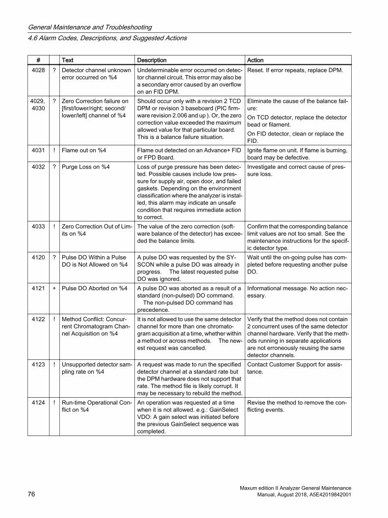
# Text Description Action4028 ? Detector channel unknown
error occurred on %4Undeterminable error occurred on detec‐tor channel circuit. This error may also be a secondary error caused by an overflow on an FID DPM.
Reset. If error repeats, replace DPM.
4029, 4030
? Zero Correction failure on [first/lower/right; second/lower/left] channel of %4
Should occur only with a revision 2 TCD DPM or revision 3 baseboard (PIC firm‐ware revision 2.006 and up ). Or, the zero correction value exceeded the maximum allowed value for that particular board. This is a balance failure situation.
Eliminate the cause of the balance fail‐ure: On TCD detector, replace the detector bead or filament. On FID detector, clean or replace the FID.
4031 ! Flame out on %4 Flame out detected on an Advance+ FID or FPD Board.
Ignite flame on unit. If flame is burning, board may be defective.
4032 ? Purge Loss on %4 Loss of purge pressure has been detec‐ted. Possible causes include low pres‐sure for supply air, open door, and failed gaskets. Depending on the environment classification where the analyzer is instal‐led, this alarm may indicate an unsafe condition that requires immediate action to correct.
Investigate and correct cause of pres‐sure loss.
4033 ! Zero Correction Out of Lim‐its on %4
The value of the zero correction (soft‐ware balance of the detector) has excee‐ded the balance limits.
Confirm that the corresponding balance limit values are not too small. See the maintenance instructions for the specif‐ic detector type.
4120 ? Pulse DO Within a Pulse DO is Not Allowed on %4
A pulse DO was requested by the SY‐SCON while a pulse DO was already in progress. The latest requested pulse DO was ignored.
Wait until the on-going pulse has com‐pleted before requesting another pulse DO.
4121 + Pulse DO Aborted on %4 A pulse DO was aborted as a result of a standard (non-pulsed) DO command. The non-pulsed DO command has precedence.
Informational message. No action nec‐essary.
4122 ! Method Conflict: Concur‐rent Chromatogram Chan‐nel Acquisition on %4
It is not allowed to use the same detector channel for more than one chromato‐gram acquisition at a time, whether within a method or across methods. The new‐est request was cancelled.
Verify that the method does not contain 2 concurrent uses of the same detector channel hardware. Verify that the meth‐ods running in separate applications are not erroneously reusing the same detector channels.
4123 ! Unsupported detector sam‐pling rate on %4
A request was made to run the specified detector channel at a standard rate but the DPM hardware does not support that rate. The method file is likely corrupt. It may be necessary to rebuild the method.
Contact Customer Support for assis‐tance.
4124 ! Run-time Operational Con‐flict on %4
An operation was requested at a time when it is not allowed. e.g.: GainSelect VDO: A gain select was initiated before the previous GainSelect sequence was completed.
Revise the method to remove the con‐flicting events.
General Maintenance and Troubleshooting4.6 Alarm Codes, Descriptions, and Suggested Actions
Maxum edition II Analyzer General Maintenance76 Manual, August 2018, A5E42019842001
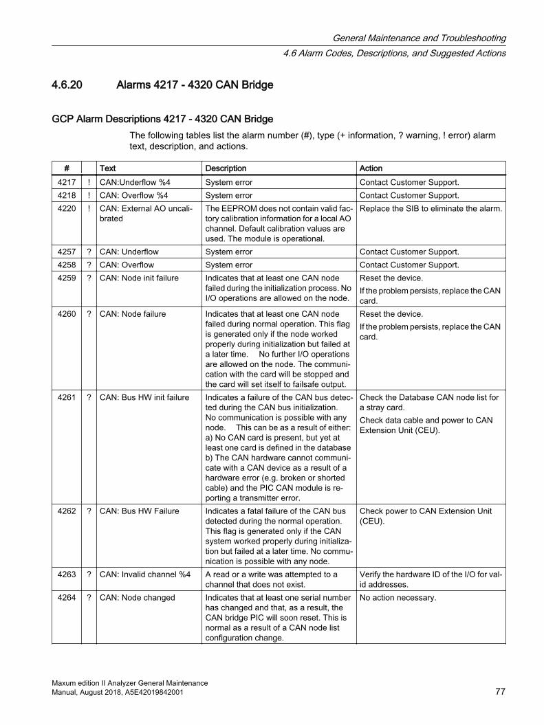
4.6.20 Alarms 4217 - 4320 CAN Bridge
GCP Alarm Descriptions 4217 - 4320 CAN BridgeThe following tables list the alarm number (#), type (+ information, ? warning, ! error) alarm text, description, and actions.
# Text Description Action4217 ! CAN:Underflow %4 System error Contact Customer Support.4218 ! CAN: Overflow %4 System error Contact Customer Support.4220 ! CAN: External AO uncali‐
bratedThe EEPROM does not contain valid fac‐tory calibration information for a local AO channel. Default calibration values are used. The module is operational.
Replace the SIB to eliminate the alarm.
4257 ? CAN: Underflow System error Contact Customer Support.4258 ? CAN: Overflow System error Contact Customer Support.4259 ? CAN: Node init failure Indicates that at least one CAN node
failed during the initialization process. No I/O operations are allowed on the node.
Reset the device.If the problem persists, replace the CAN card.
4260 ? CAN: Node failure Indicates that at least one CAN node failed during normal operation. This flag is generated only if the node worked properly during initialization but failed at a later time. No further I/O operations are allowed on the node. The communi‐cation with the card will be stopped and the card will set itself to failsafe output.
Reset the device.If the problem persists, replace the CAN card.
4261 ? CAN: Bus HW init failure Indicates a failure of the CAN bus detec‐ted during the CAN bus initialization. No communication is possible with any node. This can be as a result of either: a) No CAN card is present, but yet at least one card is defined in the database b) The CAN hardware cannot communi‐cate with a CAN device as a result of a hardware error (e.g. broken or shorted cable) and the PIC CAN module is re‐porting a transmitter error.
Check the Database CAN node list for a stray card. Check data cable and power to CAN Extension Unit (CEU).
4262 ? CAN: Bus HW Failure Indicates a fatal failure of the CAN bus detected during the normal operation. This flag is generated only if the CAN system worked properly during initializa‐tion but failed at a later time. No commu‐nication is possible with any node.
Check power to CAN Extension Unit (CEU).
4263 ? CAN: Invalid channel %4 A read or a write was attempted to a channel that does not exist.
Verify the hardware ID of the I/O for val‐id addresses.
4264 ? CAN: Node changed Indicates that at least one serial number has changed and that, as a result, the CAN bridge PIC will soon reset. This is normal as a result of a CAN node list configuration change.
No action necessary.
General Maintenance and Troubleshooting4.6 Alarm Codes, Descriptions, and Suggested Actions
Maxum edition II Analyzer General MaintenanceManual, August 2018, A5E42019842001 77
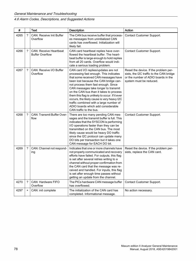
# Text Description Action4265 ? CAN: Receive Init Buffer
OverflowThe CAN bus receive buffer that process‐es messages from uninitialized CAN cards has overflowed. Initialization will likely fail.
Contact Customer Support.
4266 ? CAN: Receive Heartbeat Buffer Overflow
CAN card heartbeat replies have over‐flowed the heartbeat buffer. The heart‐beat buffer is large enough to hold replies from all 20 cards. Overflow would indi‐cate a serious loading problem.
Contact Customer Support.
4267 ? CAN: Receive I/O Buffer Overflow
CAN card I/O replies/updates are not processing fast enough. This indicates that some received CAN messages have been lost because the CAN bridge can‐not process them fast enough. Since CAN messages take longer to transmit on the CAN bus than it takes to process them this flag is unlikely to occur. If it ever occurs, the likely cause is very heavy I2C traffic combined with a large number of ADIO boards which add considerable CAN traffic to the bus.
Reset the device. If the problem per‐sists, the I2C traffic to the CAN bridge or the number of ADIO boards in the system must be reduced.
4268 ? CAN: Transmit Buffer Over‐flow
There are too many pending CAN mes‐sages and the transmit buffer is full. This indicates that the SYSCON is performing I/O operations faster than they can be transmitted on the CAN bus. The most likely cause would be heavy DO traffic since the I2C protocol can update many DO bits per transaction but it takes one CAN message for EACH DO bit.
Contact Customer Support.
4269 ? CAN: Channel not respond‐ing
Indicates that one or more channels have not properly communicated and recovery efforts have failed. For outputs, this flag is set after several retries writing to a channel without proper confirmation from the CAN card that the message was re‐ceived and handled. For inputs, this flag is set after enough time passes without getting an update from the channel.
Reset the device. If the problem per‐sists, replace the CAN card.
4270 ? CAN: Hardware FIFO Overflow
The PICs hardware CAN message buffer has overflowed.
Contact Customer Support.
4297 + CAN: init complete The initialization of the CAN card has completed. Informational message.
No action necessary.
General Maintenance and Troubleshooting4.6 Alarm Codes, Descriptions, and Suggested Actions
Maxum edition II Analyzer General Maintenance78 Manual, August 2018, A5E42019842001
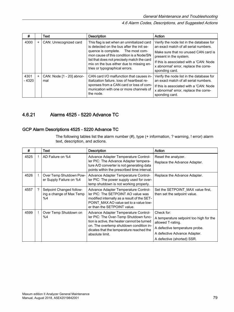
# Text Description Action4300 + CAN: Unrecognized card This flag is set when an uninitialized card
is detected on the bus after the init se‐quence is complete. The most com‐mon cause of this condition is a Node/SN list that does not precisely match the card mix on the bus either due to missing en‐tries or typographical errors.
Verify the node list in the database for an exact match of all serial numbers. Make sure that no unused CAN card is present in the system. If this is associated with a 'CAN: Node x abnormal' error, replace the corre‐sponding card.
4301 - 4320
+ CAN: Node [1 - 20] abnor‐mal
CAN card I/O malfunction that causes in‐itialization failure, loss of heartbeat re‐sponses from a CAN card or loss of com‐munication with one or more channels of the node.
Verify the node list in the database for an exact match of all serial numbers. If this is associated with a 'CAN: Node x abnormal' error, replace the corre‐sponding card.
4.6.21 Alarms 4525 - 5220 Advance TC
GCP Alarm Descriptions 4525 - 5220 Advance TCThe following tables list the alarm number (#), type (+ information, ? warning, ! error) alarm text, description, and actions.
# Text Description Action4525 ! AD Failure on %4 Advance Adapter Temperature Control‐
ler PIC: The Advance Adapter tempera‐ture A/D converter is not generating data points within the prescribed time interval.
Reset the analyzer. Replace the Advance Adapter.
4526 ! Over Temp Shutdown Pow‐er Supply Failure on %4
Advance Adapter Temperature Control‐ler PIC: The power supply used for over‐temp shutdown is not working properly.
Replace the Advance Adapter.
4557 ? Setpoint Changed follow‐ing a change of Max Temp %4
Advance Adapter Temperature Control‐ler PIC: The SETPOINT AO value was modified internally as a result of the SET‐POINT_MAX AO value set to a value low‐er than the SETPOINT value.
Set the SETPOINT_MAX value first, then set the setpoint value.
4599 ! Over Temp Shutdown on %4
Advance Adapter Temperature Control‐ler PIC: The Over-Temp Shutdown func‐tion is active, the heater cannot be turned on. The overtemp shutdown condition in‐dicates that the temperature reached the absolute limit.
Check for: A temperature setpoint too high for the allowed T-rating. A defective temperature probe. A defective Advance Adapter. A defective (shorted) SSR.
General Maintenance and Troubleshooting4.6 Alarm Codes, Descriptions, and Suggested Actions
Maxum edition II Analyzer General MaintenanceManual, August 2018, A5E42019842001 79
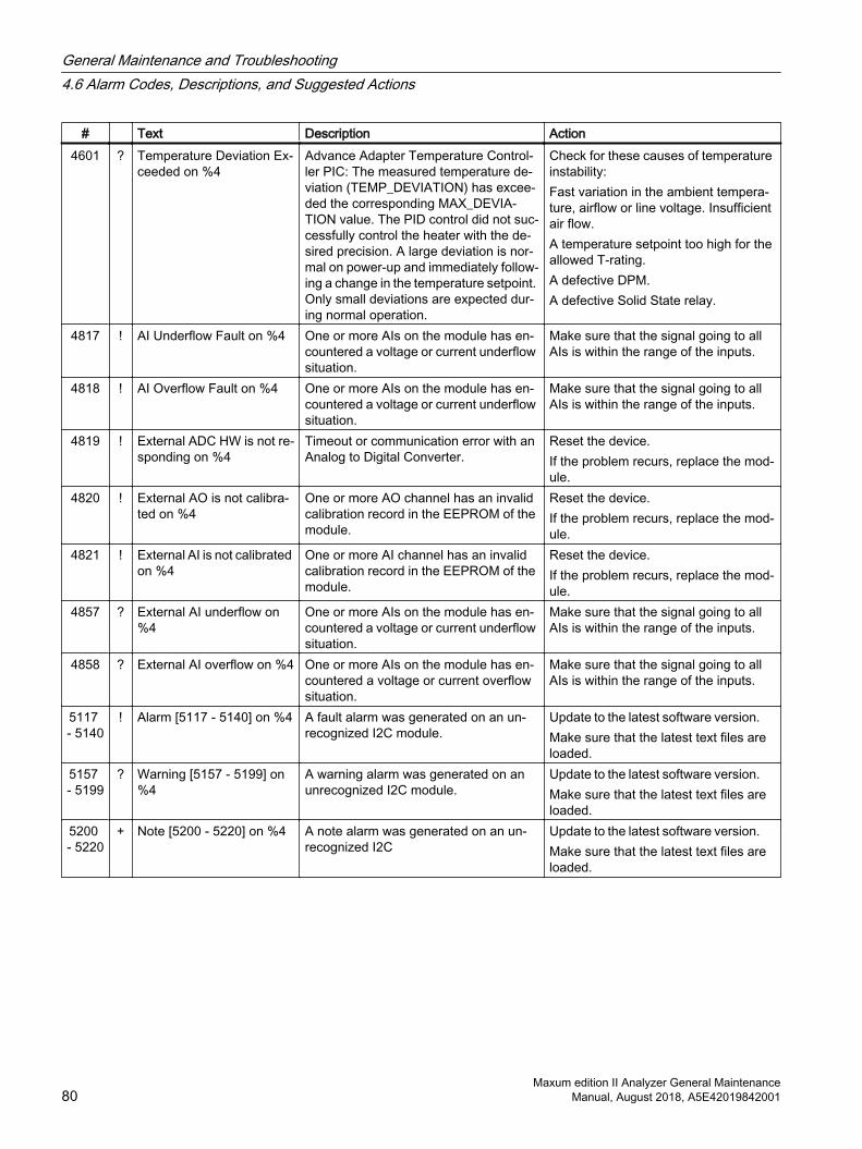
# Text Description Action4601 ? Temperature Deviation Ex‐
ceeded on %4Advance Adapter Temperature Control‐ler PIC: The measured temperature de‐viation (TEMP_DEVIATION) has excee‐ded the corresponding MAX_DEVIA‐TION value. The PID control did not suc‐cessfully control the heater with the de‐sired precision. A large deviation is nor‐mal on power-up and immediately follow‐ing a change in the temperature setpoint. Only small deviations are expected dur‐ing normal operation.
Check for these causes of temperature instability: Fast variation in the ambient tempera‐ture, airflow or line voltage. Insufficient air flow. A temperature setpoint too high for the allowed T-rating. A defective DPM. A defective Solid State relay.
4817 ! AI Underflow Fault on %4 One or more AIs on the module has en‐countered a voltage or current underflow situation.
Make sure that the signal going to all AIs is within the range of the inputs.
4818 ! AI Overflow Fault on %4 One or more AIs on the module has en‐countered a voltage or current underflow situation.
Make sure that the signal going to all AIs is within the range of the inputs.
4819 ! External ADC HW is not re‐sponding on %4
Timeout or communication error with an Analog to Digital Converter.
Reset the device. If the problem recurs, replace the mod‐ule.
4820 ! External AO is not calibra‐ted on %4
One or more AO channel has an invalid calibration record in the EEPROM of the module.
Reset the device. If the problem recurs, replace the mod‐ule.
4821 ! External AI is not calibrated on %4
One or more AI channel has an invalid calibration record in the EEPROM of the module.
Reset the device. If the problem recurs, replace the mod‐ule.
4857 ? External AI underflow on %4
One or more AIs on the module has en‐countered a voltage or current underflow situation.
Make sure that the signal going to all AIs is within the range of the inputs.
4858 ? External AI overflow on %4 One or more AIs on the module has en‐countered a voltage or current overflow situation.
Make sure that the signal going to all AIs is within the range of the inputs.
5117 - 5140
! Alarm [5117 - 5140] on %4 A fault alarm was generated on an un‐recognized I2C module.
Update to the latest software version. Make sure that the latest text files are loaded.
5157 - 5199
? Warning [5157 - 5199] on %4
A warning alarm was generated on an unrecognized I2C module.
Update to the latest software version. Make sure that the latest text files are loaded.
5200 - 5220
+ Note [5200 - 5220] on %4 A note alarm was generated on an un‐recognized I2C
Update to the latest software version. Make sure that the latest text files are loaded.
General Maintenance and Troubleshooting4.6 Alarm Codes, Descriptions, and Suggested Actions
Maxum edition II Analyzer General Maintenance80 Manual, August 2018, A5E42019842001

4.6.22 Alarms 10000 - 11536 MicroSAM
GCP Alarm Descriptions - 10000 - 11536 MicroSAMThe following tables list the alarm number (#), type (+ information, ? warning, ! error) alarm text, description, and actions.
# Text Description Action10000 ! Temperature control failure
on %4MicroSAM alarm Contact MicroSAM Support.
10001 ! Temperature sensor (RTD) of %4 defective
MicroSAM alarm Contact MicroSAM Support.
10002 ! Temperature deviation on %4 exceeds limits
MicroSAM alarm Contact MicroSAM Support.
10003 ! Temperature controller %4 disabled
MicroSAM alarm Contact MicroSAM Support.
10004 ! Carrier gas pressure low on %4
MicroSAM alarm Contact MicroSAM Support.
10256 ! Detector %4 disabled MicroSAM alarm Contact MicroSAM Support.10257 ! Detector %4 shorted MicroSAM alarm Contact MicroSAM Support.10258 ! Detector %4 not connected MicroSAM alarm Contact MicroSAM Support.10259 ! Carrier gas pressure low
on %4MicroSAM alarm Contact MicroSAM Support.
10512 ! Pressure controller %4 dis‐abled
MicroSAM alarm Contact MicroSAM Support.
10513 ! A/D converter failure on %4 MicroSAM alarm Contact MicroSAM Support.10514 ? Operating pressure low on
%4MicroSAM alarm Contact MicroSAM Support.
10515 ! Pressure exceeds limits on %4
MicroSAM alarm Contact MicroSAM Support.
10516 ! Setpoint exceeds limits on %4
MicroSAM alarm Contact MicroSAM Support.
10517 ! Pressure out of control on %4
MicroSAM alarm Contact MicroSAM Support.
10518 ! Voltage exceeds limits on %4
MicroSAM alarm Contact MicroSAM Support.
10519 ! Operating pressure low MicroSAM alarm Contact MicroSAM Support.10768
- 10775
! Valve [1 – 8] operation fail‐ure on %4
MicroSAM alarm Contact MicroSAM Support.
11536 ! General RSP communica‐tion error on %4
MicroSAM alarm Contact MicroSAM Support.
General Maintenance and Troubleshooting4.6 Alarm Codes, Descriptions, and Suggested Actions
Maxum edition II Analyzer General MaintenanceManual, August 2018, A5E42019842001 81
General Maintenance and Troubleshooting4.6 Alarm Codes, Descriptions, and Suggested Actions
Maxum edition II Analyzer General Maintenance82 Manual, August 2018, A5E42019842001
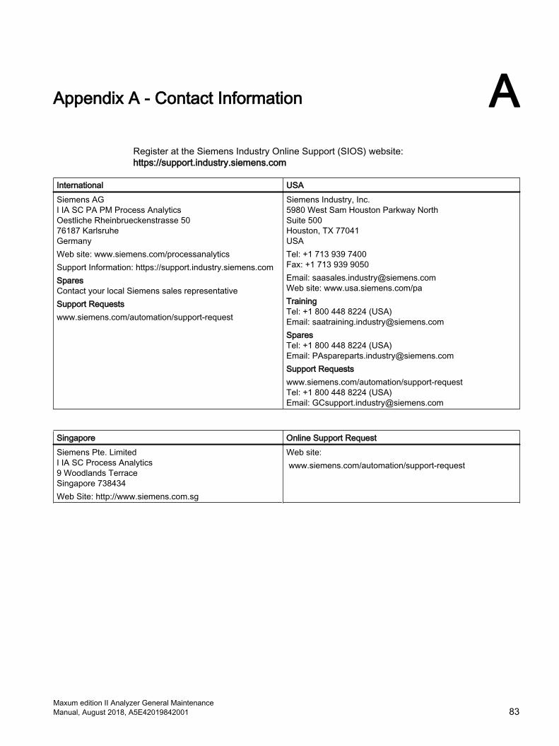
Appendix A - Contact Information ARegister at the Siemens Industry Online Support (SIOS) website:https://support.industry.siemens.com
International USASiemens AGI IA SC PA PM Process AnalyticsOestliche Rheinbrueckenstrasse 5076187 Karlsruhe GermanyWeb site: www.siemens.com/processanalyticsSupport Information: https://support.industry.siemens.comSparesContact your local Siemens sales representativeSupport Requestswww.siemens.com/automation/support-request
Siemens Industry, Inc.5980 West Sam Houston Parkway North Suite 500Houston, TX 77041USATel: +1 713 939 7400Fax: +1 713 939 9050Email: [email protected] site: www.usa.siemens.com/paTrainingTel: +1 800 448 8224 (USA)Email: [email protected]: +1 800 448 8224 (USA)Email: [email protected] Requestswww.siemens.com/automation/support-requestTel: +1 800 448 8224 (USA)Email: [email protected]
Singapore Online Support RequestSiemens Pte. LimitedI IA SC Process Analytics9 Woodlands TerraceSingapore 738434Web Site: http://www.siemens.com.sg
Web site: www.siemens.com/automation/support-request
Maxum edition II Analyzer General MaintenanceManual, August 2018, A5E42019842001 83

Appendix A - Contact Information
Maxum edition II Analyzer General Maintenance84 Manual, August 2018, A5E42019842001

Index
AApplet, 9Applet Module, 9Application, 9
CColumns, 15
DDHCP, 30
EEC, 15Ethernet IP, 30
FFilament, 16Flame Ionization, 16Flame Photometric, 16
IIP address, 30
MMethod, 9
PPulsed Discharge, 16
SSensor Near Electronics, 12Sensor Near Electronics software module, 12SNE, 12SNE functions, 13
TThermistor, 16
Maxum edition II Analyzer General MaintenanceManual, August 2018, A5E42019842001 85

Index
Maxum edition II Analyzer General Maintenance86 Manual, August 2018, A5E42019842001