me 450, fall 2012 final report
TRANSCRIPT

ME 450, Fall 2012
Instructor: Elijah Kannatey-Asibu
Final Report 11 December 2012
X-Ray Microtags for the Detection of
Post-Operative Foreign Objects
Sponsored by:
Dr. Theodore Marentis
Professor Nikolaos Chronis
Team 4 Brian Arntfield
Kristine Kruppa
Michelle Pascual
Mackenzie Wilson

2
Executive Summary
Our project was to develop a manufacturing process for x-ray microtags designed by our sponsors. The
sponsor requirements for our project were: the microtags must have 4 tungsten-carbide beads, the beads
must be 1.3 +0.3/ -0.1 mm apart, the total tag size must be 3 x 3 x 3 +2.5/ -0.5 mm, the plastic for the tags
must be FDA-approved, the tags must be able to undergo sterilization, the total material cost should not
exceed $0.04 per tag, the tags must be attachable to surgical instruments using an FDA-approved
adhesive, the tags must be initially 95% ± 5% detectable by the Computer Aided Detection (CAD)
software, and the tags must be manufactured using the Knight DC16AP heat press in our sponsors’ lab.
These translated into our engineering specifications in descending order of importance: the 4 tungsten
carbide beads must be 1.3 +0.3/ -0.1 mm apart, the plastic we choose must melt between 140-350°C, the
total material cost should not exceed $0.04 per tag, the tags must be initially 95% ± 5% detectable by our
sponsor’s CAD software, and the total size of the tags should be 3 x 3 x 3 +2.5/ -0.5 mm.
Our team developed concepts for our design by functional decomposition, individual brainstorming, and
group brainstorming sessions. We evaluated the five best concepts using a Pugh Chart (Table 2, p. 14)
and chose a design involving a system of plates (Concept A, p. 9). However, when we created a scale
model of this design, we noticed an unforeseen complication related to the size of the beads compared to
the size of the cutting ridges. Based on this, we altered the design and evaluated the new version using a
Pugh Chart. This concept received the highest rating and was therefore chosen as our Alpha design. This
Alpha design featured two plates to hold the tungsten-carbide beads, one flat plate to contain the plastic,
one hollow cavity plate for the bottom, and one cutting plate to separate the tags. The cavity plate is used
for a vacuum that verifies the beads placement. A plastic sheet is placed between the plates and beads are
melted separately into each side using the heat press, then the tags are cut apart with the cutting plate.
Our final design was an evolved version of the Alpha design and is described on page 15. This final
design used the entire surface of the heat press plates to create as many tags as possible and minimized
the number of presses by incorporating two cutting axes into one die. However, after considering the
manufacturing time for this design, we determined that it would be preferable to create a proof-of-concept
prototype instead. The prototype was smaller than the final design and could only create 100 microtags at
once, having 200 holes on each bead die. It also had a cutting die with blades along a single axis.
We fabricated our prototype in the ME Undergraduate Machine shop using the band saw, mill, CNC mill,
and arbor press. We used the band saw to cut the aluminum sheets into pieces and the mill to size and
shape these pieces. The CNC mill was used to create 200 holes in each bead die for the tungsten-carbide
beads. We used the arbor press to press-fit dowel pins for locating into the plates. The cost of purchased
and gifted materials/equipment for our design totaled $4045.86. See the final design section on page 21
and the fabrication section on page 36 for more information.
The tests we performed on the prototype are described in the section on page 38. We tested the vacuum
system, agitator, and heat press and then tested our plates by creating microtags. The agitator was very
effective for placing the beads and the UHMWPE plastic pressed in a reasonable amount of time. We
experienced some problems with the beads not implanting completely, the cutting ridges not cutting
completely through the plastic, and the plates being difficult to separate after being pressed. We also
found that the current vacuum design is not able to detect an individual bead missing from the bead die.
There were additional issues caused by inaccuracies in the manufacturing of our plates because we were
not able to achieve the necessary tolerances in the ME Undergraduate Machine Shop. Based on these
tests, we advise carrying out the recommendations in the section on page 50 and testing them with a new
iteration of the design.
3
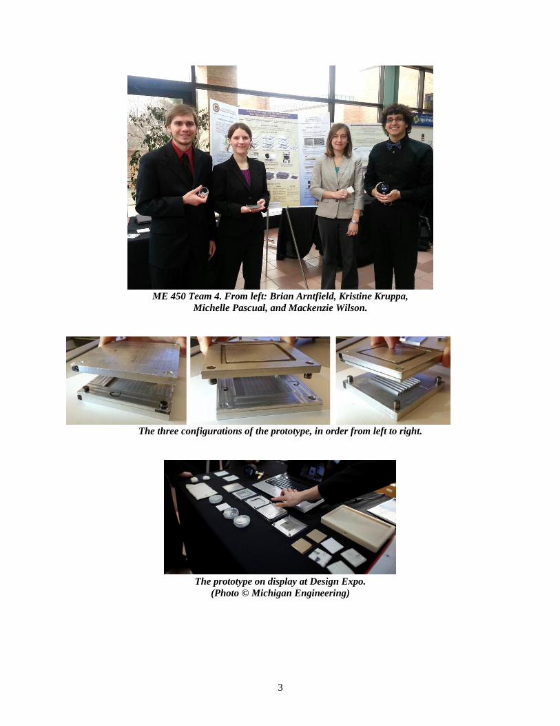
ME 450 Team 4. From left: Brian Arntfield, Kristine Kruppa,
Michelle Pascual, and Mackenzie Wilson.
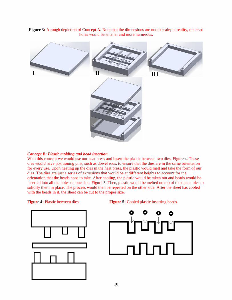
The three configurations of the prototype, in order from left to right.
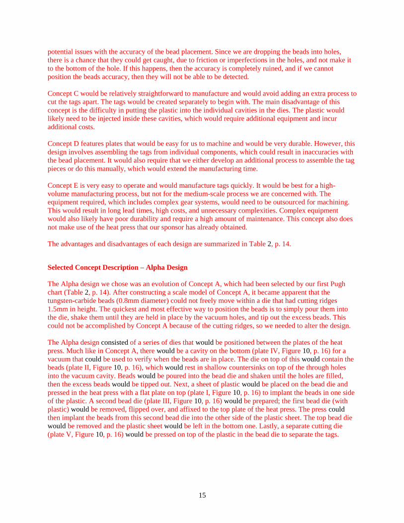
The prototype on display at Design Expo.
(Photo © Michigan Engineering)

4
Table of Contents
Introduction ................................................................................................................................................. 6 Revised Abstract ........................................................................................................................................... 6 Problem Description .................................................................................................................................... 6 Engineering Specifications ......................................................................................................................... 6 Order of Importance of Engineering Targets ............................................................................................. 8 Concept Generation .................................................................................................................................... 8 Concept A ..................................................................................................................................................... 9 Concept B ................................................................................................................................................... 10 Concept C ................................................................................................................................................... 11 Concept D ................................................................................................................................................... 11 Concept E ................................................................................................................................................... 12 Concept Selection Process ........................................................................................................................ 13 Concept Advantages and Disadvantages ................................................................................................... 14 Selected Concept Description – Alpha Design ........................................................................................ 15 Engineering Design Parameter Analysis ................................................................................................. 17 Heat Transfer Analysis .............................................................................................................................. 17 Die Material Analysis ................................................................................................................................. 19 Mircotag Material Analysis ....................................................................................................................... 19 Manufacturing Process Selection ............................................................................................................. 20 Design for Environmental Sustainability (SimaPro) ................................................................................ 20 Design for Safety ........................................................................................................................................ 20 Final Design Description .......................................................................................................................... 21 Prototype Description ............................................................................................................................... 29 Changes from the Final Design ................................................................................................................ 29 Prototype Design ........................................................................................................................................ 29 Initial Fabrication Plan ............................................................................................................................ 35 Validation Results ..................................................................................................................................... 37 Vacuum Experiment .................................................................................................................................. 37 Agitator Experiment ................................................................................................................................... 38 Bead Embedding Experiments .................................................................................................................. 39 Cutting Die Experiment ............................................................................................................................. 41 Adhesive Experiment ................................................................................................................................. 42 Specification Validation ............................................................................................................................. 43 Discussion .................................................................................................................................................. 44 Strengths of Design .................................................................................................................................... 44 Weaknesses of Design ................................................................................................................................ 45 Recommendations ..................................................................................................................................... 49 Original Information Sources .................................................................................................................. 49 Patents ........................................................................................................................................................ 49 Competitor Comparison ............................................................................................................................. 50 Materials ..................................................................................................................................................... 50 Milling the Die ........................................................................................................................................... 51 Injection Molding Feasibility .................................................................................................................... 52 Vacuum Holding ........................................................................................................................................ 52 Acknowledgements ................................................................................................................................... 52 Conclusions ................................................................................................................................................ 53 References .................................................................................................................................................. 55 Appendix A ................................................................................................................................................ 56 Appendix B ................................................................................................................................................ 57

5
Appendix C ................................................................................................................................................ 62 Appendix D ................................................................................................................................................ 67 Appendix E ................................................................................................................................................ 74 Appendix F ................................................................................................................................................ 77 Appendix G ................................................................................................................................................ 78

6
Introduction
Our project was to develop a manufacturing process that will be used to create x-ray microtags for the
detection of post-operative foreign objects. Surgical sponges and towels are occasionally left inside
patients after surgeries, resulting in complications that can be severe. By attaching microtags designed
and tested by our sponsors, Professor Nikos Chronis and Dr. Theodore Marentis, we hope to eliminate
this problem. The microtags can be detected on x-rays using a Computer Aided Detection program that
will determine if an object has been left inside a patient. By developing a medium-scale manufacturing
process for these tags, we will allow them to be used and tested within the University of Michigan
hospitals.
Revised Abstract
Gossypibomas are foreign objects accidentally retained inside the human body during a surgical
procedure. These objects—usually surgical sponges—are difficult to see on x-ray images and can cause
severe complications [1]. To aid in the detection of these objects, Professor Nikos Chronis and Theodore
Marentis have designed and tested a microtag that appears on x-rays. The goal of our project was to
develop, build, and test a medium-scale manufacturing process for these tags. They are created in a sheet,
broken apart, checked for quality, and affixed to surgical sponges for use in the University of Michigan
Hospitals.
Problem Description
Our task was to develop a manufacturing process for the x-ray microtags developed by our sponsors
Professor Nikos Chronis in the University of Michigan Mechanical Engineering Department and
Theodore Marentis in the University of Michigan Radiology Department. These x-ray microtags are used
in conjunction with sponges and towels to make them more recognizable on an x-ray. The motivation
behind this project was the high number of instances where foreign objects are accidently left in the body
following a surgical procedure (1 in 1000 to 1 in 1500) [2]. Ultimately, the goal of this project was to find
a low cost method of manufacturing these microtags, so that they can be a viable solution to the expensive
alternatives offered today to tag surgical equipment, and reduce the instances of foreign objects left after
surgery.
Engineering Specifications
The project sponsors had nine engineering requirements that needed to be met: the microtags needed 4
tungsten carbide beads, the beads had to be spaced 1.3 mm apart, the overall size of the tags needed to be
approximately 3 x 3 x 3 mm, the plastic encasing the tags had to be FDA-approved, the tags needed to be
able to withstand sterilization, the total material cost could not exceed $0.04 per tag, the tags had to be
attachable to surgical instruments using an FDA-approved adhesive, the tags needed to be initially 95%
detectable by the Computer Aided Detection (CAD) software, and the tags had to be manufactured using
the Knight DC16AP heat press present in the sponsor’s lab.
The majority of our sponsor requirements translated directly into engineering specifications. However,
there were several open-ended requirements that necessitated additional research and planning to
quantify. We found that heat sterilization takes place at 132°C (270°F) [3], so the melting temperature of
our material must be sufficiently higher to avoid warping or melting. In addition, the heat press (Geo
Knight & Co., Inc. DC16AP) used for manufacturing has an upper limit of 260° C (500° F), so our
material must become malleable enough at this temperature to be able to insert the tungsten carbide
beads. From this data, we estimated that the melting temperature of our material had to be approximately
140-350°C (284 to 662° F).

7
Most standard adhesives are either chemical or thermal, so our microtags needed to be able to withstand
whichever attachment method we chose. If we chose an FDA-approved chemical adhesive, we would
need to test our materials and determine if they are affected by the chemical. If we chose a thermal
adhesive, we would need to ensure that the plastic is able to withstand the temperature without deforming.
A Quality Function Deployment (QFD) worksheet was used to further develop our engineering targets
(Figure 1). The order of importance of our sponsor requirements is represented by the weight ratings in
our QFD. Higher weights represent more important requirements, with 5 being the maximum. We
decided against technical benchmarking because other designs use different methods of detection.
Figure 1: The QFD we used to determine our engineering targets.

8
Order of Importance of Engineering Targets
Based on our QFD results, we determined that the most important engineering targets were the space
between the beads and the melting temperature of our material. The bead spacing is critical because the
CAD software can only detect a certain orientation. Bead spacing also affects the height, length, and
width of the tags because the beads must be firmly encased within the plastic housing while maintaining a
1.3 mm separation. Total material cost can be affected by the bead spacing because adding beads or
plastic increases the material cost. The melting temperature of the material is important because it
determines which adhesive to use and which sterilization processes can be used. Since the melting
temperature affects the material choice, it also affect the manufacturability and price of the microtags.
The total material cost of the microtag is the next important engineering target because it determines
whether the tags are competitive and economical. Price is a critical factor in decisions related to beads,
materials, adhesives, and processes. By keeping the total material cost of the microtags low, we can make
our product more attractive to hospitals and consumers.
An additional important engineering target is the percent of our microtags that are initially detectable by
the CAD software. In order to keep the cost of the microtags to a minimum and reduce the possibility of
faulty tags, our goal was to achieve an initial rate of 95% detectable by customer software.
The last engineering requirements are the height, length, and width of the finished microtags. These
parameters are be based on the spacing between the beads.
The order of importance of our engineering targets in summarized in Table 1. The tolerances were based
on discussions with our sponsors.
Table 1: Order of importance of engineering targets and tolerances.
Rank Order Item Target
1 Melting temperature of plastic 140-350° C
2 Spacing between beads 1.3 +0.3/ -0.1 mm
3 Total material cost of tag $0.04
4 Percent initially detectable by customer software 95% ± 5%
5 Height, Length, Width 3 +2.5/ -0.5 mm
Concept Generation
Our team generated concepts by creating a functional decomposition of our processes (Figure 2, p. 9),
brainstorming individually, and holding group brainstorming sessions. We used our functional
decomposition to determine the inputs and outputs that would be needed for each step of our process. This
helped to organize and construct our ideas more efficiently. We next brainstormed individually; resulting
ideas were many and varied, but fell into several general categories: sheet forming, cavity forming,
interior skeleton structures, and manufacturing systems that did not use the heat press. Sheet forming used
the heat press to melt the beads into a sheet of plastic, then cutting that sheet apart into individual
microtags. Cavity forming, on the other hand, used the heat press to melt the beads into separate plastic
cavities that would not need to be cut apart. Interior skeleton structures would hold the beads in place
with a frame that is later incorporated into the tag. Ideas that did not use the heat press were naturally less
restricted and more difficult to categorize. Five of our best concepts are described below; the rest are
included in Appendix D, p. 67.

9
Figure 2: The functional decomposition of our general process. We focused on designing the
manufacturing and cutting systems, since those are the areas that will require the most components to be
manufactured.
Concept A: Sheet forming using a vacuum and ridges This concept falls into the ‘sheet forming’ category and was used as a base to compare our designs. Its
main piece is a metal bead-holding die that holds the beads in place (plate II, Figure 3, p. 10). There are
numerous thin through holes in the die at the bead positions that are countersunk slightly into the surface.
Behind these holes, there is a cavity attached to a vacuum system (plate III, Figure 3, p.10). First, beads
are poured into the die and shaken until they are all in position. Air is evacuated from the cavity behind
the holes in order to lower the pressure and hold the beads into place. Next, the excess beads are tipped
out (while maintaining the vacuum to hold the other beads in position). The die is then secured in the heat
press and a plastic sheet is placed on top. The heat press is turned on and melts the plastic between the
bead-holding die and a flat metal plate on top (plate I, Figure 3, p. 10). When the press reaches a certain
temperature, the vacuum shuts off so the beads can melt into the plastic without becoming dislodged.
Ridges are built into the bead-holding die to separate the microtags halfway under pressure. The plates
then come apart, the sheet is allowed to cool, and then it is removed from the press. The plastic sheet is
flipped and rotated 90 degrees and the process is repeated so the second pairs of beads can be implanted.
The cutting ridges finish separating the tags on the second press because they engage from the opposite
side.
10
Figure 3: A rough depiction of Concept A. Note that the dimensions are not to scale; in reality, the bead
holes would be smaller and more numerous.
Concept B: Plastic molding and bead insertion
With this concept we would use our heat press and insert the plastic between two dies, Figure 4. These
dies would have positioning pins, such as dowel rods, to ensure that the dies are in the same orientation
for every use. Upon heating up the dies in the heat press, the plastic would melt and take the form of our
dies. The dies are just a series of extrusions that would be at different heights to account for the
orientation that the beads need to take. After cooling, the plastic would be taken out and beads would be
inserted into all the holes on one side, Figure 5. Then, plastic would be melted on top of the open holes to
solidify them in place. The process would then be repeated on the other side. After the sheet has cooled
with the beads in it, the sheet can be cut to the proper size.
Figure 4: Plastic between dies. Figure 5: Cooled plastic inserting beads.

11
Concept C: Cavity forming using a vacuum This concept is part of the ‘cavity forming’ category and is similar to Concept A in the sense that it uses a
vacuum to hold the beads in place. However, in this concept there are two bead-holding dies—one on top
of the plastic and one below (plates II and IV, Figure 6). Thin through holes drilled into each die are
countersunk slightly for the tungsten carbide beads to fit into. The beads are held in place using a vacuum
system that lowers the pressure in cavities underneath the through holes (plates I and V, Figure 6). Similar
to Concept A, beads are poured into each die, held in place by the vacuum, and melted into plastic placed
in between. The main difference between this idea and Concept A is that this design has no ridges around
the perimeter of the microtags. Instead, plastic is injected into cylindrical cavities in a separate die (plate
III, Figure 6), which is then placed between the two bead placement dies. The beads are then heat-pressed
into the cylindrical cavities filled with plastic. Once the plastic has cooled, it is punched out of the die
using a metal plate with posts that push the tags out of the cylindrical cavities. In this way, the microtags
would be formed separately and would not need to be cut apart.
Figure 6: A rough depiction of Concept C. Note that the dimensions are not to scale; in reality, the bead
and plastic holes would be smaller and more numerous.
Concept D: Skeleton building blocks
This design would involve constructing many identical C-shaped pieces. During the forming of these
pieces the beads would be held in the bottom of the die using a vacuum. Pre-cut plastic blocks matching

12
the shape of the pieces would be put in each shape of the die, before being covered by a flat plate and
melted using the heat press. Once the pieces were melted and removed from the initial die following
cooling they would then need to be melted again into their interlocking form using a second set of dies.
After they had cooled they could then be removed in their final shape.
Figure 7: An illustration of Concept D.
Concept E: Rotating manufacturing using a spool of plastic This concept would involve feeding a plastic rope with a square cross-section through two sets of wheels.
The first set would press heated beads into each side of the plastic (object C, Figure 8; object A/B/C,
Figure 9, p.13). The second set would cut the tags apart (objects E and F, Figure 8, p. 12). Both sets of
wheels would be driven by a single motor (object B, Figure 8; object D, Figure 9, p.13) using gears
attached to the wheels. The first set of wheels, which places the beads, would use a powerful vacuum
system (object G, Figure 9, p.13) to draw the beads from a heated hopper (object D, Figure 8) into
precisely drilled holes around its circumference. The plastic rope would be drawn through these wheels
and the beads would be pressed into it. Next, the plastic rope would pass through a second set of wheels,
one of which would feature cutting blades around its circumference (object E, Figure 8), and the other of
which would be flat and freely rotating (object F, Figure 8). These wheels would cut the plastic rope into
individual tags [4].
Figure 8: Illustration of Concept E.
Label Object
A Spool of plastic rope
B Motor (drives all gears)
C Bead-pressing geared wheels
D Heated bead hoppers
E Cutting geared wheel
F Freely-rotating wheel

13
Figure 9: Illustration of bead-pressing geared wheels in Concept E.
Concept Selection Process
After developing our five concepts we evaluated them using a Pugh chart (Table 2, p. 14). In this process
we selected Concept A to be the base design by which the other four designs were compared to and then
given a rating on a one to five scale according to certain weighted criteria. A design that met the criteria
well received a five, while a design that did not meet the criteria received a one.
Heavily weighted criteria are as follows:
Bead positioning accuracy – How well the manufacturing process places the beads in the correct
orientation in the tag. Bead positioning accuracy is critical because it determines whether or not
the tag can be detected by our sponsors’ x-ray software. A design which could repeatedly place
the beads 1.3mm apart and in a 3-D orientation received a higher rating.
Ease to manufacture equipment – How easy it will be for us to manufacture the additional
equipment required, such as plates, dies, or gears. This was especially important because we have
strict time constraints and we needed to ensure that we could physically manufacture, or order
any needed equipment in time for a final product to be produced. Designs that incorporated
additional equipment that was easier to manufacture, in terms of the amount of tools or machines
required to create them, received a higher rating.
Ease to manufacture tags – The effort and numbers of steps required to actually produce a
useable tag. This was important in terms of our shortened timeline, and to make sure that anyone
producing the tags in the future would be able to make them within a reasonable time frame.
Designs that were less complex in terms of getting from plastic material to individual tags were
rated higher.
Ease of user operation – How easy it is for the user to operate the equipment. This was
important because we wanted to keep the process as simple as possible so anyone creating the
tags in the future would not have to learn an extensive set of operations. Designs that had a high
number of user inputs received lower ratings than more automated concepts.
Manufacturing time – The amount of time required to produce a useable tag. Manufacturing
time was important because the sponsors wanted many tags to be created in a short amount of
time, and reduce the amount of time it might keep someone from their other duties. Designs with
a shorter manufacturing time – the time from going from the separate plastic material and beads
to individual tags – were given a higher rating.
Label Object
A Gears
B Wheels holding the beads
C Lower supports
D Motor (only on one gear)
E Plastic rope
F Bearings
G Vacuum connections

14
The moderately weighted criteria are as follows:
Use of heat press – How well the manufacturing process design incorporates the provided heat
press. The heat press was provided equipment that we hoped to use to help reduce manufacturing
costs, but it was not weighted more heavily because we did not want to limit our designs to
having to use the heat press. Designs which used the heat press for the entire manufacturing
process of producing a tag were given a higher rating.
Equipment longevity – The lifetime of the additional equipment manufactured. We hoped to
keep manufacturing costs down for the sponsor by hopefully using equipment that would last
longer, but as it would be possibly difficult to estimate how long the equipment would last, we
did not consider it to be heavily important. Designs with additional equipment we suspected
would last a longer time, due to the materials it was made of, how complex it was, the lifetime of
its components, or how often it was used through the process, were given a higher rating.
The low weighted criterion is as follows:
Cost of additional equipment – The total cost of producing or purchasing additional equipment
required to complete the manufacturing process. This was rated the lowest due to the cost not
being the most important criteria established by our sponsor. Designs which cost less were given
a higher rating.
Once all the concepts were rated, their rating was multiplied by the associated weight for each criterion
and summed. The best design had the highest score. Concept A resulted in the highest score, simply
because each of the other four concepts failed in heavily weighted categories that were essential for a
successful final product. In addition, Concept A was rather simple and would require less equipment to be
manufactured. This concept process also helped us to develop a more final concept.
Table 2: The Pugh chart used to select our alpha design.
Concept
A
Concept
B
Concept
C
Concept
D
Concept
E
Selection Criteria Weight
Rating Rating Rating Rating Rating
Bead positioning accuracy 0.20 3 1 3 1 2
Ease to manufacture equipment 0.15 3 2 4 3 1
Ease to manufacture tags 0.15 3 2 2 1 4
Ease of user operation 0.15 3 2 2 2 4
Manufacturing time 0.10 3 2 3 2 4
Use of heat press 0.10 3 4 3 4 1
Equipment longevity 0.10 3 2 2 3 1
Cost of additional equipment 0.05 3 3 1 3 1
Total Score 3.0 2.05 2.65 2.15 2.4
Rank 1 5 2 4 3
Concept Advantages and Disadvantages
Concept A was the base design that we used as a comparison for the others. It performed fairly well in
every selection category.
Concept B would require no additional equipment, besides plates and dies, so would be simple to
implement. However, it has many possible problems related to the durability of the dies. The extrusions
on the dies would need to be very small (approximately 1mm in diameter). If the plastic is not completely
malleable when pressure is applied, these small diameter extrusions could easily be bent. There are also
15
potential issues with the accuracy of the bead placement. Since we are dropping the beads into holes,
there is a chance that they could get caught, due to friction or imperfections in the holes, and not make it
to the bottom of the hole. If this happens, then the accuracy is completely ruined, and if we cannot
position the beads accuracy, then they will not be able to be detected.
Concept C would be relatively straightforward to manufacture and would avoid adding an extra process to
cut the tags apart. The tags would be created separately to begin with. The main disadvantage of this
concept is the difficulty in putting the plastic into the individual cavities in the dies. The plastic would
likely need to be injected inside these cavities, which would require additional equipment and incur
additional costs.
Concept D features plates that would be easy for us to machine and would be very durable. However, this
design involves assembling the tags from individual components, which could result in inaccuracies with
the bead placement. It would also require that we either develop an additional process to assemble the tag
pieces or do this manually, which would extend the manufacturing time.
Concept E is very easy to operate and would manufacture tags quickly. It would be best for a high-
volume manufacturing process, but not for the medium-scale process we are concerned with. The
equipment required, which includes complex gear systems, would need to be outsourced for machining.
This would result in long lead times, high costs, and unnecessary complexities. Complex equipment
would also likely have poor durability and require a high amount of maintenance. This concept also does
not make use of the heat press that our sponsor has already obtained.
The advantages and disadvantages of each design are summarized in Table 2, p. 14.
Selected Concept Description – Alpha Design
The Alpha design we chose was an evolution of Concept A, which had been selected by our first Pugh
chart (Table 2, p. 14). After constructing a scale model of Concept A, it became apparent that the
tungsten-carbide beads (0.8mm diameter) could not freely move within a die that had cutting ridges
1.5mm in height. The quickest and most effective way to position the beads is to simply pour them into
the die, shake them until they are held in place by the vacuum holes, and tip out the excess beads. This
could not be accomplished by Concept A because of the cutting ridges, so we needed to alter the design.
The Alpha design consisted of a series of dies that would be positioned between the plates of the heat
press. Much like in Concept A, there would be a cavity on the bottom (plate IV, Figure 10, p. 16) for a
vacuum that could be used to verify when the beads are in place. The die on top of this would contain the
beads (plate II, Figure 10, p. 16), which would rest in shallow countersinks on top of the through holes
into the vacuum cavity. Beads would be poured into the bead die and shaken until the holes are filled,
then the excess beads would be tipped out. Next, a sheet of plastic would be placed on the bead die and
pressed in the heat press with a flat plate on top (plate I, Figure 10, p. 16) to implant the beads in one side
of the plastic. A second bead die (plate III, Figure 10, p. 16) would be prepared; the first bead die (with
plastic) would be removed, flipped over, and affixed to the top plate of the heat press. The press could
then implant the beads from this second bead die into the other side of the plastic sheet. The top bead die
would be removed and the plastic sheet would be left in the bottom one. Lastly, a separate cutting die
(plate V, Figure 10, p. 16) would be pressed on top of the plastic in the bead die to separate the tags.

16
Figure 10: The individual plates used in the Alpha concept.
Figure 11: The sequence of dies used for the Alpha concept.
While the process may seem complicated, it is actually quite simple besides the fact that it would require
switching out dies a number of times. Switching dies was necessary because we required a separate
cutting die to avoid using ridges integrated into a bead die. We also found it necessary to position the dies
filled with beads on the bottom to avoid having them fall out. This resulted in a second die switch-out.

17
After developing this concept, our team compared it to the previous top designs using a Pugh chart (Table
3). The new Alpha design received the highest rating.
Table 3: The second Pugh chart that we used to confirm the selection of our Alpha concept.
Concept
A
Concept
B
Concept
C
Concept
D
Concept
E
Alpha
Design
Selection Criteria Weight
Rating Rating Rating Rating Rating Rating
Bead positioning accuracy 0.20 3 1 3 1 2 4
Ease to manufacture equipment 0.15 3 2 4 3 1 3
Ease to manufacture tags 0.15 3 2 2 1 4 2
Ease of user operation 0.15 3 2 2 2 4 4
Manufacturing time 0.10 3 2 3 2 4 4
Use of heat press 0.10 3 4 3 4 1 3
Equipment longevity 0.10 3 2 2 3 1 3
Cost of additional equipment 0.05 3 3 1 3 1 3
Total Score 3.0 2.1 2.7 2.2 2.5 3.3
Rank 2 6 3 5 4 1
To supplement our previous general functional decomposition, we created a functional decomposition
specifically for our Alpha design (Figure 12, p. 17). This allowed us to easily analyze the necessary inputs
and outputs at each stage of the process.
Figure 12: The functional decomposition for our specific Alpha design.
Engineering Design Parameter Analysis
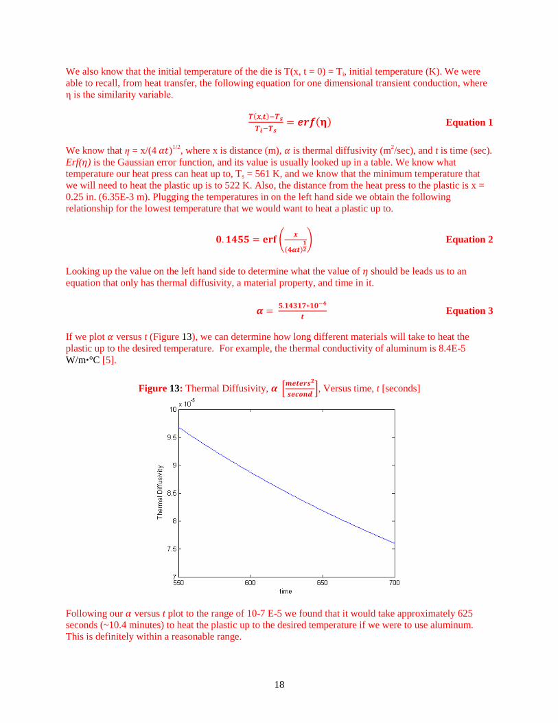
Heat Transfer Analysis
For this analysis we assumed a one dimensional transient conduction problem with constant surface
temperature. With constant surface temperature we know that T(x = 0, t) = Ts, surface temperature (K).
18
We also know that the initial temperature of the die is T(x, t = 0) = Ti, initial temperature (K). We were
able to recall, from heat transfer, the following equation for one dimensional transient conduction, where
η is the similarity variable.
( )
( ) Equation 1
We know that η = x/(4 )1/2, where x is distance (m), is thermal diffusivity (m
2/sec), and t is time (sec).
Erf( ) is the Gaussian error function, and its value is usually looked up in a table. We know what
temperature our heat press can heat up to, Ts = 561 K, and we know that the minimum temperature that
we will need to heat the plastic up is to 522 K. Also, the distance from the heat press to the plastic is x =
0.25 in. (6.35E-3 m). Plugging the temperatures in on the left hand side we obtain the following
relationship for the lowest temperature that we would want to heat a plastic up to.
(
( )
) Equation 2
Looking up the value on the left hand side to determine what the value of should be leads us to an
equation that only has thermal diffusivity, a material property, and time in it.
Equation 3
If we plot versus t (Figure 13), we can determine how long different materials will take to heat the
plastic up to the desired temperature. For example, the thermal conductivity of aluminum is 8.4E-5
W/m∙°C [5].
Figure 13: Thermal Diffusivity, [
], Versus time, t [seconds]
Following our versus t plot to the range of 10-7 E-5 we found that it would take approximately 625
seconds (~10.4 minutes) to heat the plastic up to the desired temperature if we were to use aluminum.
This is definitely within a reasonable range.

19
Die Material Analysis
To determine an ideal material for the dies a material analysis was done using the CES Edupack 2012.
Materials were analyzed based on having a minimum service temperature above 350 °C so they would
not melt when in contact with the heat press, costing less than $10/kilogram, having a thermal
conductivity above 50 W/m °C. The thermal conductivity was determined based on a rough thermal
conductivity number of steel, which is a common die material in manufacturing. Plotting thermal
conductivity against price/kilogram showed 13 materials that could be potential die materials (Figure 14,
p. 19). However, as we are concerned with heating up the microtag plastic we wanted a material with the
highest thermal conductivity possible to reduce the time required to melt the plastic. Therefore, aluminum
was chosen as the die material.
Figure 14: The plot associated with the die material analysis, showing 13 potential materials for the dies.
Mircotag Material Analysis
To determine an ideal material for the microtags a material analysis was done using the CES Edupack
2012. Materials were analyzed based on having a melting point between 140 °C and 350 °C so they
would work with our heat press, and having an excellent durability against 10% Hydrochloric acid (HCl),
the lowest concentration of HCL available in the program and chosen to make sure the material would not
deteriorate if it ever came in contact with stomach acid. Plot melting point against price showed six
potential materials for microtag (see Figure 15, p. 20). Lead was eliminated due to the harm it causes to
the human body. Further analysis was done on the remaining materials based on their FDA approval for
medical use. Therefore for our final design the microtags will be made of PEEK.

20
Figure 15: The plot associated with the mircrotag material analysis, showing six potential materials for
the mircrotags.
Manufacturing Process Selection
After determining the materials of two components, we evaluated using CES Edupack which
manufacturing methods would be best suited for each material. In the case of the aluminum dies we chose
to use Electric Discharge Machining because it was the method that could best produce the strict
tolerances of some of the dies. In the case of the PEEK for the microtags, we were only concerned with
how to cut a sheet of PEEK into the desired size needed to produce a sheet of tags. Therefore, to best
meet cutting the PEEK on a large scale we would recommend punching. A detailed explanation of this
process can be found in Appendix C.
Design for Environmental Sustainability (SimaPro)
We compared aluminum and steel in an Environmental Performance Analysis done in SimaPro. This
allowed us to determine which of the two materials had a greater environmental impact. Based on the
mass of emissions from raw, air, water, and waste, we found that aluminum had higher emissions than
steel. In addition, we compared the EcoIndicator 99 point values for aluminum and steel and found that
aluminum had a higher value. This implies that aluminum has more emission points than steel, most of
which are from mineral emissions.
When considering the full life cycle of both steel and aluminum, aluminum has more of an environmental
impact over its life cycle. Aluminum parts wear out faster and thus need to be replaced at a greater rate.
The full analysis is included in Appendix C.
Design for Safety
A Designsafe analysis was done for the manufacturing of the dies to the creation of the microtags. During
manufacturing of the dies the only associated hazard would be cutting/severing due to using the band saw
and mill. Most of the hazards would originate from using the heat press to create the microtags. Hazards
of using the heat press include crushing, pinch points, radiant heat, hot surfaces, and compressed air. The
risks associated with these hazards and how we would work to prevent them is outlined in Appendix G.

21
Final Design Description
Our final design is a slightly evolved version of the concept described in the ‘Selected Concept
Description – Alpha Design’ section (p. 15). It features a system of plates that fit into the DC-16AP heat
press in our sponsor’s lab. The major design changes from the Alpha Design included altering the vacuum
plate so that it could accommodate a NPT 1/16 inch diameter threaded pipe fitting, separating the ridge
from the bead dies, changing the thicknesses of the plates so they could be machined from standard sizes,
and removing the inner edge from the vacuum plate.
The plates will be made from 1/8 inch, 1/4 inch, and 1/2 inch aluminum stock. We have selected
PolyEtherEtherKetone (PEEK) and Ultra-High-Molecular-Weight-Polyethylene (UHMWPE) for the
plastics that will encase the tungsten-carbide beads.
The design is operated by the following steps:
1) Turn on the heat press and adjust the temperature, pressure, and press time as desired. For
UHMWPE, the temperature should be at 400 ºF, the time should be 8:00 minutes, and the
pressure should be 60 psi.
2) Place the ridge onto the first bead die and secure both on the agitator. Turn on the agitator and
adjust the speed to 1.5 on the dial.
3) Carefully pour tungsten-carbide beads into the bead die and allow them to shake into place. Once
all beads appear to be in place, remove the plates from the agitator (without disrupting the beads).
4) Attach a hose from the vacuum pump through the pressure gage fitting assembly to the hole in the
vacuum plate. Place the first bead die and ridge on top of the vacuum plate and turn on the
vacuum.
5) Use the pressure gage to verify that all the beads are in place. If beads are missing, repeat the
agitator procedure above. If beads are not missing, turn off the vacuum and continue to step 5.
6) Place a piece of PEEK or UHMWPE into the first bead die without disturbing the beads. Place
the flat plate on top of the plastic.
7) Lift the bead die, ridge, plastic, and flat plate off the vacuum plate and place them into the heat
press. Engage the press by simultaneously pressing both black buttons. For UHMWPE, it should
press for 8:00 minutes.
8) When the heat press disengages automatically, remove the plates using a heat-resistant glove or
pliers. Place the plates together onto a thick piece of scrap aluminum to cool. For UHMWPE,
allow them to cool for 10 minutes.
9) When the plates are cool, carefully remove the flat top plate, ridge, and plastic.
10) Place the second bead die onto the agitator, place the ridge on top, and drop one loose locating
pin into each of the corner holes to secure them. Turn on the agitator and adjust the speed to 1.5
on the dial.
11) Carefully pour tungsten-carbide beads into the bead die and allow them to shake into place. Once
all beads appear to be in place, remove the plates from the agitator (without disrupting the beads).
12) Remove the dowel pins. Place the second bead die and ridge on top of the vacuum plate and turn
on the vacuum.
13) Use the pressure gage to verify that all the beads are in place. If bead are missing, repeat the
agitator procedure above. If beads are not missing, turn off the vacuum and continue to step 14.
14) Place the same piece of PEEK or UHMWPE into the second bead die without disturbing the
beads. The side with the beads already implanted should be facing up and the plastic should be
rotated 90º from the original direction of implantation. Place the first bead die onto the top of the
plastic.

22
15) Lift the bead dies, ridge, and plastic off the vacuum plate and place them into the heat press.
Engage the press by simultaneously pressing both black buttons. For UHMWPE, it should press
for 8:00 minutes.
16) When the heat press disengages automatically, remove the plates using a heat-resistant glove or
pliers. Place the plates together onto a thick piece of scrap aluminum to cool. For UHMWPE,
allow them to cool for 10 minutes.
17) When the plates are cool, carefully remove the first bead die. Leave the plastic and ridge attached
to the second bead die.
18) Place the cutting plate on top of the second bead die. Lift the bead die, ridge, plastic, and cutting
plate into the heat press.
19) Engage the press by pressing both black buttons. For UHMWPE, it should press for 2:30 minutes.
20) When the heat press disengages automatically, remove the plates using a heat-resistant glove or
pliers. Place the plates together onto a thick piece of scrap aluminum to cool. For UHMWPE,
allow them to cool for 10 minutes.
21) When the plates are cool, carefully separate all the plates. Remove the plastic.
22) Using a razor blade, carefully cut apart any microtags that were not fully separated by the cutting
plate.
The figures below show the various plates that will make up our design, as well as the order that they will
be used in (Figure 22, p.26).
Figure 16: The vacuum plate for our final design. All dimensions are in mm with a tolerance of 0.1 mm
unless other specified.

23
Figure 17: The bead die for our final design. All dimensions are in mm with a tolerance of 0.1 mm unless
other specified.

24
Figure 18: The flat plate for our final design. All dimensions are in mm with a tolerance of 0.1 mm
unless otherwise specified.

25
Figure 19: The bead die for our final design. All dimensions are in mm with a tolerance of 0.1 mm unless
other specified.
Figure 20: The ridge plate for our final design. All dimensions are in mm with a tolerance of 0.1 mm
unless other specified.
26
Figure 21: The cutting plate for our final design. All dimensions are in mm with a tolerance of 0.1 mm
unless other specified.
Figure 22: The sequence of dies that will be used for our final design, starting from the image at the
left.
We will first use one bead die to press the beads into one side of the plastic, then use both bead dies to
press beads into the other side of the plastic, and then cut the microtags apart using the cutting plate.
Figure 23, p. 27 depicts the system that will be used to shake the beads into position. Figure 24, p. 27
shows how the heat press system will operate. The labels in green were parts given to us by the laboratory
and the labels in purple were purchased.

27
Figure 23: A diagram of the set up for the agitator and vacuum system used to position the beads.
Figure 24: A diagram of the set up for the heat press and compressed air system used to implant the
beads into the plastic.
There was a variety of parts and equipment necessary for our design. The parts that we purchased or
borrowed from our sponsors’ lab are listed in Table 4, p. 28, and the parts that we fabricated ourselves are
listed in Table 5, p. 28.

28
Table 4: The off-the-shelf parts that were purchased or borrowed.
Part Source Part # Cost ($) Function
Automatic, Swing-away Heat
Press
Knight & Co.,
Inc (Lab)
Knight
DC16AP
2250.00 Heats up and press together
plates and plastic.
¼” Fem x 1/8” Male Pipe
Adapter
McMaster-Carr 50785K26 1.46 Pipe connector for vacuum.
1/8” fem x 1/16” Male Pipe
Adapter
McMaster-Carr 9171K231 6.40 Pipe connector for vacuum
¼” Tube x ¼” NPT Male
Pipe Fitting
McMaster-Carr 5463K247 0.46 Pipe connector for vacuum
Brass Threaded Pipe Fitting
¼” Fem x Fem x Male Tee
McMaster-Carr 50785K222 4.60 Tee pipe connector for
vacuum.
Digital Gage, 30 PSI McMaster-Carr 2798K21 88.89 Allows measurement of the
pressure in the vacuum plate.
UHMW Polyethylene 1/8”
Thick x 12” x 12”
McMaster-Carr 8270K21 9.39 Encases beads.
PEEK 1/8” Thick x 6” x 6” McMaster-Carr 8504K75 94.04 Encases beads.
Tungsten Carbide Beads
0.8mm Dia.
Salem
Specialty Ball
(Lab)
N/A 558.00 Allows microtag to be detected
by x-rays
Thermo Scientific Titer Plate
Shaker
Thermo
Scientific (Lab)
4625-Q 1017.00 Shakes beads into position
Industrial Razor Blade Navistar (Lab) SMR
11304B100
$12 per
100
Finishes cutting microtags
apart after cutting plate
Vacuum system Lab -- -- Verifies that beads are in place
Compressed air system Lab -- -- Necessary for heat press
Connecting tubes Lab -- -- Connect systems
¼” Dia, ½” long Dowel Pins
(x8)
ME Undergrad
Machine Shop
McMaster-
Carr
98381A537
$3.62
per 25
Locate plates relative to one
another
TOTAL 4045.86
TOTAL SPENT BY TEAM 205.24
Table 5: The parts that we fabricated in-house.
Part Material(s)
Vacuum plate 1/2 inch aluminum
Bead die 1 1/4 inch aluminum, ¼” dowel rods (x4)
Bead die 2 1/4 inch aluminum
Flat top plate 1/4 inch aluminum
Cutting plate 1/2 inch aluminum, ¼” dowel rods (x4)
Ridge 1/8 inch aluminum
This final design is the one that best optimized the heat press and other equipment available to us. It uses
the entire surface of the heated plates to create as many tags as possible and minimizes the number of
presses by incorporating cutting in both directions into one die. However, after considering the time in

29
which the design must be created, we determined that it would be preferable to create a proof-of-concept
prototype rather than the full design.
Prototype Description
Changes from the Final Design
In order to determine whether it would be possible to create the complete final design in the ME
Undergraduate Machine Shop, we used the CNC mill to machine an aluminum test plate. We drilled
several holes in a piece of 1/4 inch thick aluminum stock using a 1/64 inch diameter drill bit. From this
test, we discovered that it would take approximately 10 minutes to machine each of the bead holes
because only a small amount of material can be removed with each press of the bit. There are 1872 holes
in each of the two bead dies in the final design, which means that we would need to create 3744 holes in
total. At 10 minutes per hole, it would take 26 days to drill the bead holes in both the parts. Therefore, we
determined that it was not possible for us to create the full-scale design in the time available to us.
However, we decided to create a prototype in order to prove that our concept is valid. This prototype
would create 100 microtags at once and would have 200 holes on each bead die. The CNC milling of both
bead dies for the small prototype would take only 2.8 days.
We also decided to change the design for our prototype cutting die in order to make it feasible to machine.
The original cutting die featured cutting blades along two axes that would be able to completely separate
the microtags in a single press. However, the tight tolerances and exact corners required for a two-axis
cutting die surpass the abilities of the ME Undergraduate Machine Shop. We investigated electrical
discharge machining (EDM) as a possible alternative, but this option was too slow for us to complete in
our time frame. Therefore, we decided to prototype a cutting die with blades along only one axis. The die
is symmetrical so that we can simply rotate it in order to cut in the other direction. This was much simpler
to create in the machine shop and still allowed us to test its ability to separate the microtags.
Prototype Design
The prototype we created is very similar to our final design, but with several changes to simplify the
machining process. The prototype was smaller than the final design and was only be able to create 100
microtags at once. The figures below further illustrate the prototype design.

30
Figure 25: The vacuum plate for our prototype design. All dimensions are in mm with a tolerance of 0.1
mm unless other specified.

31
Figure 26: The bead die plate for our prototype design. All dimensions are in mm with a tolerance of 0.1
mm unless other specified.
Figure 27: The ridge for the bead die plate for our prototype design. All dimensions are in mm with a
tolerance of 0.1 mm unless other specified.

32
Figure 28: The flat plate for our prototype design. All dimensions are in mm with a tolerance of 0.1 mm
unless other specified.

33
Figure 29: The second bead die for our prototype design. All dimensions are in mm with a tolerance of
0.1 mm unless other specified.

34
Figure 30: The cutting plate for our prototype design. All dimensions are in mm with tolerances of 0.1
mm unless other specified.
Figure 31: The sequence of dies for our prototype design, starting from the image at the left.

35
Initial Fabrication Plan
Our prototype has six subcomponents that must be fabricated: two bead dies, a cutting die, a vacuum die,
a ridge, and a flat plate. Engineering value is added to our project in two ways by our prototype. First, our
prototype facilitates an accurate and efficient manufacturing process to create the microtags. Second, the
design of our prototype produces the maximum amount of tags with the least amount of surface area.
For the bead dies, we first cut a piece of 1/4 inch thick aluminum with the band saw. Using an edge finder
at 1000RPM on the mill, we located the edges of the piece to create a coordinate system centered at one
corner. Next, we end-milled the sides with a 1/2 inch end mill at 2400RPM to size the piece to 9 x 9 cm.
Next, the CNC mill was used with a #00 center drill and a 1/64 inch drill bit, both at 3000RPM, to drill
and countersink two hundred 1/64 inch diameter holes for the tungsten carbide beads. Then we used a 1/8
inch end mill at 2800RPM to mill down the bottom face to create a 3.5 mm deep slot around the holes for
the ridge of the vacuum plate to fit into. Then we used a #3 center drill at 1000RPM to position four
locating holes—one at each corner. For the first bead die only, we drilled and reamed these holes with a
7/32 inch drill bit at 2400RPM and a 0.249 reamer at 100RPM. We then used the arbor press to press-fit
four ½ in long, ¼ in diameter dowel pins into these holes. For the second bead die only, we drilled the
holes with a ¼ inch drill bit at 2400RPM. The prototype bead dies can be seen in Figure 26, p. 31 and
Figure 29, p. 33.
For the ridge, we first cut out a piece of 1/8 inch thick aluminum using the band saw. Using an edge
finder at 1000RPM on the mill, we located the edges of the piece to create a coordinate system centered at
one corner. Next, we end-milled the sides with a 1/2 inch end mill at 2400RPM to size the piece to 9 x 9
cm. Then we end-milled out a centered 5 x 5 cm square in the interior of this piece using a 1/4 inch end
mill at 2400RPM to take out the bulk and a 1/8 inch end mill at 2800RPM to bring it to size. This 5 x 5
cm interior area was removed in order to create an area for the plastic to fit. Next, we used a #3 center
drill at 1000RPM to position four locating holes—one at each corner. We then drilled through holes at
these points with a 1/4 inch drill bit at 2400RPM. These holes will be used for the dowel pins of the other
plates to locate to. The prototype ridge can be seen in Figure 27, p. 31.
To fabricate the cutting die, we first cut out a piece of 1/2 inch thick aluminum with the band saw. Using
an edge finder at 1000RPM on the mill, we located the edges of the piece to create a coordinate system
centered at one corner. Next, we end milled the sides with a 1/2 inch end mill at 2400RPM to size the
piece to 9 x 9 cm. Next, we used a 1/4 inch end mill at 2400RPM to mill down 3 mm into the material
around the outside of the plate to create an elevated area in the middle. Next, we used a height gage to
mark out where each of the cutting ridges would be located at in this center area. Then we adjusted the
mill to an angle of 26.7 degrees from the vertical and made a series of angled passes through the raised
center material with a 1/8 inch end mill at 2800RPM. We adjusted the mill back to vertical, then made
another series of passes through the center material with the same 1/8 inch end mill at 2800RPM to finish
the cutting ridges. We then used a #3 center drill at 1000RPM to accurately position four locating holes—
one at each corner. We then drilled ¼ inch deep holes at these points with a 7/32 inch drill bit at
2400RPM and reamed them with a 0.249 inch reamer at 100RPM. We used the arbor press to press-fit
four ½ in long, ¼ in diameter dowel pins into these holes. The prototype cutting die can be seen in Figure
30, p. 34.
To fabricate the vacuum die, we first cut a piece of 1/2 inch thick aluminum with the band saw. Using an
edge finder at 1000RPM on the mill, we located the edges of the piece to create a coordinate system
centered at one corner. Next, we end milled the sides with a 1/2 inch end mill at 2400RPM to size the
piece to 9 x 9 cm. Next, we used a 1/2 inch end mill at 2400RPM to mill down a 8 mm centered square
cavity and milled out 3 mm tall fitting ridges around the cavity using a 1/8 inch end mill at 2800RPM. We
used a #3 center drill at 1000RPM and an ‘I’ (0.272 in) drill bit at 2400RPM to drill a centered hole in

36
one side of the vacuum die. We threaded this hole by hand with a 5/16-24 SAE tap. The prototype
vacuum die can be seen in Figure 25, p. 30.
To fabricate the flat plate, we first cut a piece of 1/2 inch thick aluminum with the band saw. Using an
edge finder at 1000RPM on the mill, we located the edges of the piece to create a coordinate system
centered at one corner. Next, we end milled the sides with a 1/2 inch end mill at 2400RPM to size the
piece to 9 x 9 cm. Then we used a #3 center drill at 1000RPM to accurately position the holes for the 1/4
inch diameter dowel pins to fit into. We drilled these holes with a 1/4 inch drill bit at 2400RPM. Next, we
used the arbor press to press-fit four ½ in long, ¼ in diameter dowel pins into these holes. The prototype
flat plate can found in Figure 28, p. 32.
The main difference between our prototype and our final design is the scale. Our prototype is a scaled
down and symmetrical version of our final design. The material associated with our prototype fabrication
is aluminum. The two bead dies, the cutting die, the vacuum die, and the flat plate will all be aluminum
for the final design as well. To fabricate our prototype we used several tools and operations from the ME
Undergraduate Machine Shop. These include: CNC mill, mill, 1/64 inch drill bit, 1/4 inch drill bit, B size
drill bit, 7/32 inch drill bit, I (0.272 inch) drill bit, #00 center drill, #3 center drill, 1/2 inch end mill, 1/4
inch end mill, 1/8 inch end mill, 0.249 inch reamer, 5/16-24 SAE tap, arbor press, and band saw.
Once the plates have been manufactured, it is necessary to assemble the fittings and other equipment in
the laboratory. Assembly diagrams for this can be found in the ‘Final Design’ section, Figure 23 and
Figure 24, page 27.
The tolerances for our prototype are important in several places. First, the bead dies and cutting dies fit
together using dowel pins. The tolerances on the location of the dowel pins and the dowel holes
themselves are critical for the dies to fit together accurately. Second, the holes and countersinks are
important because they are used to hold all of the tungsten carbide beads in place. The tolerances for these
holes and countersinks are essential as the correct bead placement will correlate to correct microtags.
Finally, fitting ridges will be used in between the vacuum plate and the bead dies. The tolerances on these
fitting ridges are essential to ensure a good vacuum seal. For our prototype, the outside dimensions and
tolerances of the dies are less important since the interior of the dies is what will create the microtags.
The surfaces that are critical in our prototype as well as our final design are the top faces of the two bead
die plates. This is because the beads must accurately place in countersinks to create the correct orientation
in the microtags. If any of the 1/64 inch holes are drilled incorrectly the bead dies will produce faulty
microtags.
Initially we had planned to fabricate our full scale final design. We soon found this was not feasible. Each
of our final design bead dies required 1872 1/64 inch holes to be drilled. Since the bead dies will be made
of 1/4 inch thick aluminum, each hole would take ten minutes to drill. This equates to each bead die
taking 13 days of straight drilling on the CNC mill. Thus, we re-designed to fabricate our prototype in the
ME Undergrad Machine Shop. In addition, we realized the fitting ridges for the vacuum plate would
interfere with the dowel pins of the bead dies. To account for this, we made the dies larger and moved the
dowel pins to avoid the interference. In addition, each of our dies has been designed so that they fit well
together once each is fabricated. This was accomplished by incorporating either fitting ridges or dowel
pins into each of the dies.
37
Validation Results
We performed numerous experiments with our proof-of-concept prototype. These experiments are
summarized in the sections below.
Vacuum Experiment
There were two parts to the vacuum experiment. The first part was testing to see if we had enough
vacuum pressure to hold the beads in place while we remove the excess beads. The second part of this
experiment involves trying to determine what the pressure difference is when all the beads are in place
versus none of the bead holes are filled.
Procedure for Holding Beads in Plate: We originally used our rapid prototype to see if the vacuum in the
lab had enough pressure to hold the beads in place while we removed the excess beads. In order to do this,
we put beads in our rapid prototype and then attached the vacuum to it. After that, we tilted the rapid
prototype to see if we could remove the beads from it.
Results of Holding Beads in Place: The vacuum was strong enough to hold the beads in place and we
were able to get all of the excess beads to one side of the bead plate for removal (Figure 32). We realized
that it was much harder than we thought to remove the beads from the edge of the prototype, and this lead
to the incorporation of a removable ridge in our design (Figure 33) so we could remove it and just let the
excess beads roll off. After we manufactured our bead die, we also tried holding the beads in place with
the vacuum. We were able to completely turn the bead die upside down and the beads were kept in place
(Figure 34, p. 38).
Figure 32: Tilted rapid prototype with excess beads at one side. These beads are difficult to remove.
Figure 33: Removable ridge plate so excess beads can be easily removed.

38
Figure 34: Vacuum plate holding beads in place while die is upside down.
Procedure for Determining if Bead Holes are Filled: This experiment will start off with attaching the
vacuum to the vacuum plate and then placing the bead die on top of it. Then we will add beads and
determine what the difference in pressure is.
Results for Determining if Bead Holes are Filled: We have determined that there is approximately a 1 psi
difference when none of the bead holes are filled compared with when all of the bead holes are filled. By
dividing the change in pressure by the amount of holes, we can determine how much pressure
corresponds to how many empty bead holes. This gives us a value of 0.005 psi, and our gage only
registers to the nearest 0.01 psi. This means that we will most likely not be able to tell when only one
bead is missing. There are two main ways that we could potentially fix this. We could try adding a gasket
to get better sealing, using a more sensitive pressure gage, and/or obtaining a stronger vacuum.
Agitator Experiment
The agitator experiment will allow us to see how easily the beads will fall into place on our bead plate.
We will be testing to see how long it takes for all the beads to fill the bead die holes and which shaking
setting (1-9) should be used on the agitator to ensure that new beads can find an unfilled hole and that an
already filled hole does not lose its bead.
Procedure: The experiment will start by securely placing the bead die, which is on top of the vacuum
plate, onto the agitator (Thermo Scientific Model 4625) that was provided for us in our sponsors’ lab.
Then, the ridge plate would be placed on top of the bead die. Next, the agitator will be turned on and
beads will be placed into the bead die (Figure 35, p. 39). Once there are beads in the bead die, the settings
for the agitator will be varied to find the best speed for getting beads into place and not removing already
placed beads. Once this setting is found, the experiment will be done again to determine approximately
how long it will take to fill all of the holes. Since this prototype is small, we will be visually inspecting it
to make sure all of the bead holes are filled. Once every hole is filled, we will be using the vacuum in the
lab to hold the beads in place while we remove the ridge and tilt the bead die to allow the excess beads to
roll off.

39
Figure 35: Bead die on agitator with beads in it.
Results: It was found that an agitator speed of approximately 1.5 was adequate to allow new beads to fall
into unfilled holes while beads already in holes would not fall back out. Once this setting was found, we
re-did the experiment and found that it took approximately 2 minutes for all the holes to be filled. During
the filling process, we found that the surface of the agitator was not level which lead to beads
congregating to one side of the bead die. We then found it necessary to tilt the agitator in different
directions so all of the bead holes could be filled. If the agitator was level, like it should be in the final
design, this should not be a problem. Once all the holes were filled we realized, in the process of attaching
the vacuum, that we could tilt the bead die enough to remove the excess beads without the vacuum. This
saves a step in our process and will make it faster.
Bead Embedding Experiments
These experiments will help us determine the temperature, pressure, and length of time needed in order to
get our beads securely embedded into the plastic.
Procedure: The experiment will start off by setting the pressure, desired temperature, and length of time
to press on the heat press. While this is being done, the agitator will be used to get beads into all of the
holes, and a piece of plastic (either PEEK or UHMWPE) will be placed on top of the beads. Then the
assembly of bead plates will be placed on the heat press and the heat press will be engaged. After the
specified amount of time has passed, we will remove the bead plates and allow them to cool enough for us
to handle them and inspect how well the beads were embedded into the plastic
Results: For the first set of experiments, we were waiting for our 0.8 mm diameter beads to arrive, so we
used 0.635mm beads that were available in the lab. The first major experiment we did used PEEK and the
heat press was set to 60 psi and 500°F. We then pressed the PEEK in 2 minute intervals a total of 4 times.
We found that when the heat press disengaged after the set time, it would sometimes lift up the plates. In
one case, it knocked some of the beads out of their desired placement. After all of the pressing was done,
we found that the beads were slightly pressed into the plastic, but not enough for the beads to keep
themselves in place (Figure 36, p. 40). From these experiments we determined that we needed to increase
the heating time to give the plastic more time to become malleable so the beads would embed into the
plastic rather than fall out of place when pressing was done.
40
Figure 36: The only beads that stayed in the plastic were the beads that were knocked out of place.
Indents can be seen from where beads fell out.
We were still waiting for our 0.8 mm diameter beads to arrive when we started this next set of
experiments. This time we used UHMWPE and it was tested at 300°F and 350°F with a pressure of 45 psi
and 4 minutes. We also tried 400°F, 6 minutes, and 60 psi. The result of all three of these experiments
was that the beads did not embed far enough to stay in place when we roughly ran our fingers over the
beads.
After we received our 0.8 mm diameter beads we ran another test on the UHMWPE. Our test parameters
were 8 minutes, 60 psi, and 400°F. After the 8 minutes, we removed the plates from the heat press. After
allowing the plates to cool enough for us to handle with heat resistant gloves, we took the plastic out. In
the process, the plastic twisted slightly because it was still malleable and some of the beads came out of
place. Because of this, in the future we will allow the plastic more time to cool so the beads will better
solidify in place. Once we allowed the plastic to cool further, we found that the beads were much better
embedded than before. Aside from the beads that fell out when removing the plastic, all of the beads
stayed in place when we roughly ran our fingers over them (Figure 37).
Figure 37: Pictures of 0.8 mm beads embedded in UHWMPE.
After taking a closer look at the implanted beads, we realized that the majority of them were not
implanted enough to stay in the plastic. In order to help counteract this, we determined that we needed to
add another press. This extra press will be done once beads are on both sides of the plastic, and we will
use two flat plates to do it.
Once we knew we needed to add another step, we ran another experiment. Both sets of beads were
implanted at 400°F and 60 psi for 8 minutes. Then, in order to help further implant the beads into the

41
plastic, we did the flat plate press at 400°F and 60 psi for 1.5 minutes. The resulting plastic can be seen in
Figure 38.
Figure 38: The flat plate press implanted the beads almost level with the surface.
Cutting Die Experiment
The cutting die experiment will help us determine the temperature and pressure needed to cut our plastic
into 3 mm cubes.
Procedure: This experiment will start off by setting the temperature and pressure on the heat press. Next,
we will take our plastic (PEEK or UHMWPE) and insert it into the cutting die assembly. We will then
engage the heat press and inspect the plastic after the press was made.
Results: The first experiments we did were done with UHMWPE at 60 psi and 350°F for 2.5 minutes. In
these experiments we did two cuts on one side of the plastic. We found that the cutting die was only able
to cut about half way through the plastic. After seeing this, we thought that the temperature was not high
enough for us to easily cut through the plastic so we increased the temperature to 400°F. After doing this
and obtaining the same results, we did not want to increase the temperature anymore because we thought
that it would make the plastic too malleable and allow the beads to fall out of their intended orientation.
We then decided that it would be better to turn the plastic over and cut it two more times from the other
side (Figure 39). This worked very well, and perforated the plastic enough so we could break it into the
desired cubes.
Figure 39: UHMWPE cut 4 times, but not yet pulled apart into cubes.
The next cutting experiment we did involved cutting the plastic 2 times on each side for a total of 4 cuts.
The cutting was done at 60 psi at 400°F for 2.5 minutes. The first cut was successful (Figure 40, p. 42).
When we pulled the plastic out after the next two cuts, we found that the applied heat had re-melted most
of the previous cuts (Figure 41, p.42 ). It is likely that the plastic was pressed for too long, and in the
future we would recommend reducing the amount of time that the plastic is exposed to the heat to avoid
re-melting the previous cuts. Even though part of the plastic re-melted, we were able to cut apart the tags
by hand into the final cubes. This is shown in Figure 42, p. 42.

42
Figure 40: The first two cuts on the plastic were successful.
Figure 41: Re-melting of the previous cuts.
Figure 42: The beads embedded in plastic were successfully cut by hand into individual tags.
Adhesive Experiment
The adhesive experiment will help us determine what adhesives will work to hold our microtags into the
surgical sponges and or other equipment.
Procedure: This experiment will start off by preparing the adhesive (Medtronic Medical Adhesive
080118) and placing it onto the surgical sponge. After the adhesive is applied, the microtag will be
pressed into place and allowed to cure for 15 minutes.
Results: There were two different attachment methods that we were experimenting with. The first method
is direct attachment, which can be seen in Figure 43, p. 43. The second method uses a cover to hold the
microtag in place. We used a corner from a thin sponge as the cover, and glued the cover around a
sponge. The difference between the direct attachment and the cover attachment can be seen in Figure 44,
p. 43. After roughly pushing on the tags, we observed that they did not fall off and had successfully
adhered to the sponges.
43
Figure 43: Direct attachment method for attaching microtags to surgical sponges.
Figure 44: Cover attachment method (left) and direct attachment (right).
Specification Validation
This section will go over how well we were able to meet our engineering specifications: spacing between
the beads, percent initially detectable by customer software, total material cost of a tag, and height,
length, width of the microtags.
Spacing Between the Beads and Percent Initially Detectable by Customer Software: We were unable to
directly validate the spacing between the beads and the percent initially detectable by customer software.
The spacing between the beads should be 1.3 mm. It would be very inaccurate for us to try and measure
these dimensions by hand. We were hoping to be able to take this measurement on the x-rays when they
were taken, but we were unable to do x-ray testing on our microtags. The spacing on our bead dies are 1.3
mm, so when they are implanted, they should come out with the correct spacing. The percent initially
detectable by customer software was also not able to be tested directly. Since we were unable to take x-
rays, we were unable to actually run our microtags through our sponsors’ software. However, based on
qualitative observations of the finished microtags, it does not seem likely that we have met our target of
95% initially detectable. We were still in the process of refining our parameters, such as pressure,
temperature and time, when we made our first batch.
Total Material Cost of a Tag: Our original projected cost of each tag was about 4 cents. Originally we
were told that we had a quote of 0.8 cents per bead; however, we recently came to find out that there was
a miscommunication somewhere and that the actual quote was for 3.3 cents a bead. Once this was found
out, we realized that our target of 4 cents was unattainable because we needed to have 4 beads in each
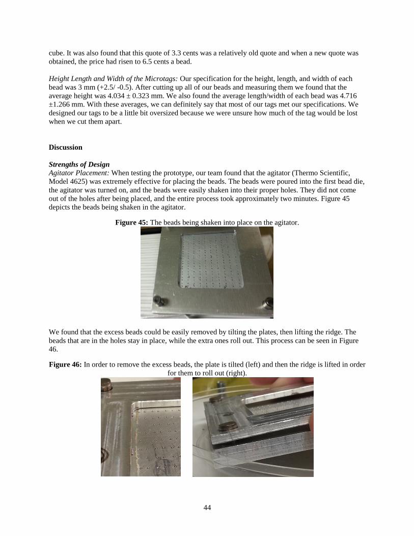
44
cube. It was also found that this quote of 3.3 cents was a relatively old quote and when a new quote was
obtained, the price had risen to 6.5 cents a bead.
Height Length and Width of the Microtags: Our specification for the height, length, and width of each
bead was 3 mm (+2.5/ -0.5). After cutting up all of our beads and measuring them we found that the
average height was 4.034 ± 0.323 mm. We also found the average length/width of each bead was 4.716
±1.266 mm. With these averages, we can definitely say that most of our tags met our specifications. We
designed our tags to be a little bit oversized because we were unsure how much of the tag would be lost
when we cut them apart.
Discussion
Strengths of Design
Agitator Placement: When testing the prototype, our team found that the agitator (Thermo Scientific,
Model 4625) was extremely effective for placing the beads. The beads were poured into the first bead die,
the agitator was turned on, and the beads were easily shaken into their proper holes. They did not come
out of the holes after being placed, and the entire process took approximately two minutes. Figure 45
depicts the beads being shaken in the agitator.
Figure 45: The beads being shaken into place on the agitator.
We found that the excess beads could be easily removed by tilting the plates, then lifting the ridge. The
beads that are in the holes stay in place, while the extra ones roll out. This process can be seen in Figure
46.
Figure 46: In order to remove the excess beads, the plate is tilted (left) and then the ridge is lifted in order
for them to roll out (right).

45
UHMWPE Pressing: We found that the Ultra-High-Molecular-Weight-Polyethylene (UHMWPE) presses
in a shorter time than we had initially anticipated. The presses to implant the beads take 8 minutes each,
the flat plate press takes 1.5 minutes, and each of the cutting presses takes 2.5 minutes or less. We found
that the entire process—including cooling and reconfiguring the plates after each step—takes less than an
hour.
Plate Cooling: The aluminum plates need to partially cool after each step in the process because this
makes it easier to remove the plastic without warping it. We found that the plates cooled fastest when
placed on a thick piece of scrap aluminum. This is due to the fact that aluminum has a high thermal
conductivity and can therefore dissipate heat quickly. We recommend using this method to cool the plates
during the final process because it is fast and effective. However, the operator must be aware that the
scrap piece used to cool the plates can become very hot with this method and should be handled with care.
Weaknesses of Design
Bead Implantation Depth: The beads do not securely implant into the plastic after pressing with the bead
dies alone (Figure 47). This could be caused by excessively deep countersinks in the bead plate. However,
we did not want to grind down the surface of the plate to reduce the countersinks because this would
make it more difficult for the beads to stay in place. With shallower countersinks, the beads could fall out
of the holes when on the agitator or when being transferred from the agitator to the press.
Figure 47: The sheet of microtags after being pressed between the bead plates. The beads do not implant
far enough and tend to fall out.
Our solution to the bead implantation problem was to add another step in the process. After pressing
beads into both sides of the plastic, we pressed the plastic again for 1.5 minutes in between two flat plates.
This forces the beads farther into the plastic and nearly eliminates the possibility of them falling out
(Figure 48).
Figure 48: The sheet of microtags after being pressed between two flat plates. The beads are implanted
much farther and do not fall out easily.
Cutting Ridge Cut Depth: The cutting ridges on the prototype plate we tested do not cut all the way
through the plastic in a single press (Figure 49, p. 46). This problem could be solved by making the
cutting ridges taller and steeper on the final design.

46
Figure 49: A microtag sheet after being pressed on one side with the cutting plate. The cutting ridges do
not cut completely through the plastic.
We attempted to solve the problem with the cutting ridges by cutting one side of the plastic, then flipping
it over and cutting the other. While this helped slightly, we do not recommend it because it added
additional time to the process, was difficult to align with the original cut, and melted plastic back into the
previous cuts.
Plastic Locating: While conducting our tests, we noticed that there were occasional problems with
locating the plastic relative to the plates. Since the plastic was not exactly the same size as the ridge
holding it in place, there was some variation in its location between the different presses. Therefore, we
recommend that the next iteration of the design include an element that could be used to locate the plastic
relative to the ridge. For example, the plastic could be initially cut to have a series of interlocking edges
along one edge that would fit into a matching configuration on the ridge. This would allow it to be located
to the same spot for every press.
Plate Locating: The prototype we manufactured experienced a number of problems locating the plates
relative to one another. The dowel pins on the cutting plate did not reach far enough to secure it to the
plates below, the cutting ridges were offset and did not line up with the original cut when the second one
was made on the opposite side, and the plates had to be assembled in specific orientations in order to fit.
The problems with dowel pins on the cutting plate were caused by a miscalculation in the dowel pin
height. The dowel pins in the final design will need to be between 2 and 5 mm longer in order to properly
reach through the ridge to the plate below.
We also experienced problems with the cutting ridges not lining up with the original cut when the plastic
was flipped. This was caused by the fact that the tip of the ridge was offset from the center (Figure 50).
Figure 50: The shape on the left is what was used for the cutting ridges in our prototype because it was
easier to manufacture. The shape on the right would be more ideal for the final design because it would
eliminate the problem with the cuts not lining up.
Another challenge we encountered while working on our prototype was that we could not achieve the
tolerances we needed in the ME Undergraduate Machine Shop. As a result, we needed to mark the edges
that we located from when machining and could only assemble the plates together when these edges were
aligned.
Pressure Verification: During the testing of the prototype, we noticed that our design was unable to detect
the presence (or absence) of individual beads. The total pressure difference between a filled and unfilled
bead die was consistently 1.00 psi, which translates to 0.005 psi per bead (200 beads). However, the

47
pressure gage that we used only had a resolution of two decimal places, which means that we could at
most detect whether two beads were present or not.
In order to be able to detect a single bead, we recommend taking any or several of the following actions:
using a higher-resolution pressure gage (able to detect differences of 0.005 psi), adding a gasket onto the
vacuum plate in order to improve the seal (and therefore increase the pressure difference in the cavity), or
using a stronger vacuum (which would also increase the pressure difference in the cavity).
Plate Separation: After each press, it is necessary to separate the plates and reassemble them into the next
configuration. However, we found that the plates tended to become stuck together and could be very
difficult to pry apart. This problem could be solved by adding a ‘keyhole’ on each edge. Such a keyhole
would provide a location where a screwdriver could be used to pry apart the plates. Another solution
could be incorporating a grease or mold separator into the process to ease the separation of the plates.
Microtag Adhesion to Sponge: We experimented with affixing our finished microtags to sponges using an
adhesive available in the lab (Medtronic Medical Adhesive 080118). One method of affixing the
microtags involved directly applying the adhesive to a sponge, then pressing a microtag onto the top of it.
With this method, the tags on the final sponges protruded significantly, creating the possibility that they
could easily be broken off. To address this potential problem, we also experimented with a second method
of microtag attachment. We cut a small square of fabric from another sponge, applied adhesive to it, and
placed it on top of a microtag resting on the sponge. This method allowed us to completely cover the
microtag while improving the aesthetic appearance of the final sponge. Therefore, we recommend either
affixing the microtag to the sponge using a cover with adhesive on it or affixing the microtag to the
sponge, then adding a cover with adhesive.
Figure 51: Examples of the microtags affixed to sponges using direct attachment (left) and using a cover
(right).
Microtag Size: There are many different types and sizes of instruments that could be left inside the body,
ranging from the larger surgical towels to tiny sponges for delicate surgeries. While our tags do not
appear as if they would interfere with the use of larger instruments, there is the potential that they could
affect the use of small sponges. The microtags would increase the thickness of small sponges by a larger
percentage and would occupy a larger percentage of the surface area. Thus, there is a stronger potential
that these tags could affect the use of small sponges. We therefore recommend that the size of the
microtags be reduced. This would lower the effect of the microtags on small sponges and could also
reduce the possibility of them breaking off. Our prototype tags were made to be slightly larger than
necessary in order to account for potential inaccuracies in the plates. If the excess plastic was eliminated,
the tags would be smaller and less prone to separating from the sponge.

48
Figure 52: Microtags affixed to smaller or thinner sponges could adversely affect the use of the sponges.
As can be seen in the photo below, the microtag protrudes significantly from the surface of the thin
sponge.
Plastic Type: We conducted tests of our design on two different plastics that our sponsors were interested
in: Ultra-High-Molecular-Weight-Polyethylene (UHMWPE) and PolyEtherEtherKetone (PEEK). The
UHMWPE became malleable quickly when the heat press was set to a temperature of 400 ºF (204 ºC), but
the PEEK did not become malleable in our tests even when the heat press was set to its maximum
temperature of 500 ºF (Figure 53). Our team had suspected this might happen, but wanted to conduct the
tests nonetheless because we wanted to determine if the temperature and pressure combination would be
enough to implant the beads. Since it was not, we recommend that either UHMWPE be used, or a heat
press with higher temperature capabilities be obtained.
Figure 53: The PEEK (left) did not become malleable enough for the beads to be implanted. However,
the UHMWPE (right) became malleable and the beads were successfully implanted.
Bead Price: We originally targeted a maximum price of $0.04 per microtag, but this was based on an
incorrect bead price. The first price we were given was $0.008 per bead, but the actual quote received by
the other researchers in our lab was $0.033 per bead. When we contacted New England Miniature Ball to
obtain an updated quote, the price rose to $0.065 per bead. Thus, the cost per tag would be $0.26 per
microtag for the beads alone. Since it is no longer possible for us to achieve the targeted cost, we would
recommend investigating other bead manufacturers. The most important aspect of the bead is its density,
since this determines how well it appears on x-rays. If the density is maintained, then we can afford to
allow the diameter of the bead to vary. By allowing for a larger variation of the bead diameter, it will be
easier to find other companies that can supply beads at a lower price.
Bead Handling: Our team had difficulty working with the 0.8 mm tungsten-carbide beads during testing.
The beads were small and tended to bounce and roll excessively when being transferred into the dies. Our
process was significantly slower because we had to take extra care not to drop any of our limited bead
stock. We would therefore recommend that the process be conducted over a large container in order to
catch falling beads. This is especially important when placing the beads into the plate on the agitator,
since we tended to lose the most during that step.

49
Recommendations
This section summarizes the recommendations we have developed based on the performance of our
design. These recommendations are explained in more detail in the ‘Discussion’ section above.
Continue to use the agitator to place the beads. It is fast, effective, and easy to use.
Cool the aluminum plates partially between each step by placing them on a thick piece of scrap
aluminum. This causes them to cool faster.
Either decrease the depth of the countersinks or press the plastic between two flat plates for 1.5
minutes after the beads are implanted. These measures would ensure that the beads are melted
farther into the plastic and will not fall out.
Design the cutting ridges to be taller and steeper on the next iteration of the design. This will
cause them to cut deeper into the plastic.
Add a plastic locating mechanism, such as a shape that the plastic fits into, in order to locate the
plastic more precisely within the dies.
Design the cutting ridges to have the point centered rather than offset.
Outsource the final plates to a professional machine shop. They should be able to achieve the
tight tolerances necessary for this design.
Either purchase a higher resolution pressure gage, add a gasket to the vacuum plate, or use a
stronger vacuum. Any of these measures would increase the ability of the design to detect the
presence of individual beads.
Design the final plates to have small keyholes at each edge. These keyholes could be used to pry
them apart after the presses.
Affix the microtags to the sponges using a cover with adhesive. This will reduce the possibility
that the microtags will be broken off.
Use UHMWPE instead of PEEK or obtain a heat press that can reach higher temperatures.
Investigate additional bead companies that could provide cheaper beads. The density of the beads
is more important than the diameter when selecting a model.
Conduct as much of the microtag creation process as possible over a large container to catch any
falling beads.
Original Information Sources
These information sources were the original research that we used when developing our design. They may
also be useful resources if modifications are made later on.
Patents
Several patents were found in relation to the detection or prevention of surgical sponges that are
inadvertently left inside of a patient.
Patent 7, 399, 899: Attachment of electronic tags to surgical sponges and implements [6]
This patent is for an electronic tag that fits into a pocket attached to a surgical instrument and can be
detected via a separate detection device. In comparison, our design uses x-rays that are already taken
rather than a separate detector. This eliminates the high up-front cost of an additional detector and avoids
adding additional tasks during the surgery.
50
Patent 7,465,847: Radiopaque marker for a surgical sponge [7]
This patent is a tag that appears in x-rays as an easily recognizable shape such as a star, diamond, or bulls-
eye target. This design is similar to ours, but does not use software to detect the tags: it uses a manual
process. Software will decrease the amount of time spent double checking x-rays and eliminates human
error.
Patent 2010/0179822 A1: System, Method and Device for Tracking Surgical Sponges [8]
This patent is for a computerized sponge counting system that ensures that the number of sponges
removed from a container equals the number discarded after the surgery. This is simply an update of the
‘count’ system already in place at hospitals that involves humans counting the instruments handed out and
taken back. There are frequent incidents of the ‘count’ being correct, but sponges still being left inside a
patient. Our microtags avoid this problem by detecting sponges directly, regardless of whether or not the
‘count’ is correct.
Competitor Comparison
If companies are already up and running to prevent surgical sponges from being left in a patient, why
should another system be developed? Currently, most sponge detection systems have some sort of
expensive equipment that accompanies the objects that are attached to the surgical sponge so they can be
detected. Another downside is the implication of new procedures that the doctors would have to squeeze
into their surgical routine. These ‘extra steps’ only slow down the surgery and leave patients under
anesthetic for longer amounts of time. RF Surgical Detection Systems, for example, uses a special “Blair-
Port Wand” to help detect if anything was left inside the patient [9]. After the surgery is done, the wand is
used to scan over the patient’s body and ensure that everything that was put in was also taken out. They
have some equipment that accompanies it that adds extra cost. Our process does not add any additional
steps to the surgical procedure. It involves taking an x-ray that is already incorporated into the process,
and running it through a program that can detect the specific signature that is given off during an x-ray.
By developing this new product, the startup cost is dramatically reduced because there is no costly
equipment; it also uses pre-existing procedures to determine if anything is left inside a patient, which
saves medical staff time and money.
Materials
Part of our project involved determining which plastic would be most suitable for our design and process.
The material that we selected needed to withstand the sterilization processes that ordinary instruments go
through before surgery. A paper, written in conjunction with the Healthcare Infection Control Practices
Advisory Committee, titled Guideline for Disinfection and Sterilization in Healthcare Facilities talks
about the most common sterilization processes. “Of all the methods available for sterilization, moist heat
in the form of saturated steam under pressure is the most widely used and the most dependable” [3]. They
then go on to say that “the two common steam-sterilizing temperatures are 121° C (250° F) and 132° C
(270° F)” [3]. If those are the two common temperatures, then our material had to be able to handle those
temperatures. If its melting point was below the sterilization temperature, then our product would melt.
The material chosen also needed to be able to be melted by our sponsor’s heat press.
Based on the temperature constraints of sterilization and the heat press, we decided to specify that the
plastic melting temperature should be between 140 and 350°C (284 to 662°F). Since this is a relatively
wide range, there were a number of plastics available to us (Table 6, p. 51). We compared the melting
temperatures of plastics available from McMaster-Carr [10], Grainger [11], and Professional Plastics [12].
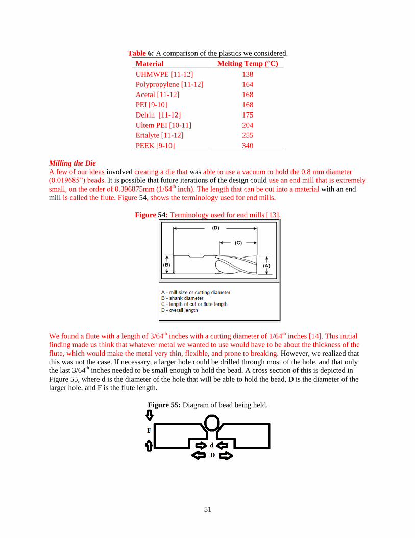
51
Table 6: A comparison of the plastics we considered.
Material Melting Temp (°C)
UHMWPE [11-12] 138
Polypropylene [11-12] 164
Acetal [11-12] 168
PEI [9-10] 168
Delrin [11-12] 175
Ultem PEI [10-11] 204
Ertalyte [11-12] 255
PEEK [9-10] 340
Milling the Die
A few of our ideas involved creating a die that was able to use a vacuum to hold the 0.8 mm diameter
(0.019685”) beads. It is possible that future iterations of the design could use an end mill that is extremely
small, on the order of 0.396875mm (1/64th inch). The length that can be cut into a material with an end
mill is called the flute. Figure 54, shows the terminology used for end mills.
Figure 54: Terminology used for end mills [13].
We found a flute with a length of 3/64th inches with a cutting diameter of 1/64
th inches [14]. This initial
finding made us think that whatever metal we wanted to use would have to be about the thickness of the
flute, which would make the metal very thin, flexible, and prone to breaking. However, we realized that
this was not the case. If necessary, a larger hole could be drilled through most of the hole, and that only
the last 3/64th inches needed to be small enough to hold the bead. A cross section of this is depicted in
Figure 55, where d is the diameter of the hole that will be able to hold the bead, D is the diameter of the
larger hole, and F is the flute length.
Figure 55: Diagram of bead being held.

52
Injection Molding Feasibility
We considered injection molding as a possible process to manufacture our microtags. The process of
injection molding mainly consists of a mold that is clamped into the molding machine and then the
desired plastic is injected into the mold. The mold is the tooling used to shape and produce plastic parts.
There are two main methods to manufacture molds: standard machining and electrical discharge
machining (EDM). Standard Machining usually involves using a CNC machine. EDM is a simple process
in which a shaped electrode, usually made of copper or graphite, is very slowly lowered onto the mold
surface while immersed in paraffin oil. A voltage applied between tool and mold causes spark erosion of
the mold surface in the inverse shape of the electrode. EDM allows the formation of shapes which are
difficult to machine, such as square corners or ribs. The process allows pre-hardened molds to be shaped
so that no heat treatment is required. Changes to a hardened mold by conventional drilling and milling
normally require annealing to soften the steel, followed by heat treatment to harden it again [15].
Though injection molding could be used for our manufacturing process there are several issues we would
have encountered. Injection molds can be expensive to manufacture and are usually only used in mass
production. Even if the cost of the plastic part being produced is low, the initial cost to produce an
injection mold is usually high. Thus the overall price will only decrease if greater quantities of the product
are produced. Also, we would have required a cooling system if we used injection molding because the
temperature inside the mold must be held constant to ensure proper forming. In addition, we would have
incurred extra costs for scrapping defective molds and replacing worn out molds. For these reasons we
concluded that injection molding was not a viable option to use for our manufacturing process [15].
Vacuum Holding
Due to a key part of our manufacturing process being dependent upon the tungsten carbide beads being
held in place by a vacuum, vacuum holding techniques were researched. A common practice in precision
machining is using a vacuum work holding device. This device is typically a grid of vacuum inlets that
help hold an object in place by a change in pressure created by a vacuum. A vacuum work holding device
works by decreasing the pressure below the object which creates a higher pressure above the object. This
higher pressure wants to fill the low pressure space below it to create equilibrium. When choosing a
vacuum pump there are two things to consider: the cubic feet per minute (CFM) – the speed of the
vacuum flow, and the inches of mercury (Hg) – the ultimate power of vacuum [16]. The pressure
sensitivity of the work holding device should also be considered.
Acknowledgements
We would like to thank our sponsors, Dr. Theodore Marentis and Professor Nikos Chronis, for allowing
us to work with them on this project. Without their information, knowledge, and resources, we would
never have been able to create or test our design. Many thanks also to the other researchers who helped us
along the way: Eleni Gourgou, Anurag Tripathi, and Amrita Chaudhury.
Our team would also like to acknowledge Professor Elijah Kannatey-Asibu Jr. for his friendly advice
throughout this course; his help was instrumental to the success of the project. His meetings kept our team
on schedule and provided valuable engineering knowledge that helped to guide our design.
Thank you also to Bob Coury and Mark Stock, without whom we could never have manufactured our
design. They provided invaluable help with all aspects of the machine shop, from how to operate the
equipment to the best machining technique. Bob also took the time to program and operate the CNC mill
in order to manufacture the complicated bead plates necessary for our project.

53
In addition, we would like to acknowledge Professor Gordon Krauss, Professor Albert Shih, Professor
Jyotirmoy Mazumder, Professor Alan Wineman, Michael Wang, Shawn O’Grady, and Shawn Salata for
their contributions to our project.
Conclusions
Our project was develop a manufacturing process for x-ray microtags developed by our sponsors. These
microtags will be used to detect objects left in patients after surgeries. These microtags consist of four
tungsten carbide beads encased in a FDA-approved plastic housing.
The sponsor requirements for our project included: the microtags must have 4 tungsten carbide beads, the
beads must be spaced 1.3mm apart, the overall size of the tags should be approximately 3 x 3 x 3 +2.5/ -
0.5 mm, the plastic encasing the tags must be FDA-approved, the tags should be able to withstand
sterilization, the total material cost should not exceed $0.04 per tag, the tags must be attachable to surgical
instruments using an FDA-approved adhesive, the tags must be initially 95% ± 5% detectable by the
Computer Aided Detection (CAD) software, and the tags must be manufactured using the Knight
DC16AP heat press present in the sponsor’s lab. These translated into the following engineering
specifications in descending order of importance: the four tungsten carbide beads must be spaced 1.3mm
apart, the plastic we choose must melt between 140-350°C, the total material cost should not exceed
$0.04 per tag, the tags must be initially 95% ± 5% detectable by our sponsor’s Computer Aided Detection
(CAD) software, and the overall size of the tags should be approximately 3 x 3 x 3 +2.5/ -0.5 mm.
We developed a variety of concepts for our design by using a functional decomposition, individual
brainstorming, and group brainstorming sessions. The five top concepts were then evaluated using a Pugh
Chart (Table 2, p. 14). Based on this evaluation, we chose to pursue a design consisting of a series of
plates that fit into the heat press (Concept A, p. 9). However, we found it necessary to alter the design
slightly after using a scale model to determine that the tungsten-carbide beads could not travel over the
cutting ridges. The new concept was also evaluated with a Pugh Chart and received the highest rating,
making it our Alpha design.
The Alpha design we chose involved a system of plates: two to hold the tungsten-carbide beads, one to
contain the plastic on the first press, one to provide a hollow vacuum cavity on the bottom, and one to cut
the tags apart. Beads would be melted separately into each side of a plastic sheet using the heat press, then
the tags would be separated using the cutting plate.
Our final design was a slightly evolved version of the Alpha design and can be found in the section on
p.15. It featured a system of plates that fit into the DC-16AP heat press in our sponsor’s lab. It used the
entire surface of the heated plates to create as many tags as possible and minimized the number of presses
by incorporating cutting in both directions into one die. However, after considering the time it would take
to create this design, we investigated to see if fabricating the final design would be feasible.
To determine if it was feasible to fabricate the complete final design in the ME Undergraduate Machine
Shop, we used the CNC mill to machine an aluminum test plate. From this test, we discovered that it
would take approximately 10 minutes to drill each of the bead holes because only a small amount of
material could be removed with each press of the bit. At 10 minutes per hole, it would take 26 days to
drill the bead holes in both bead dies for the final design.
Therefore, we determined that it was not possible for us to create the full-scale design in the time
available. The prototype we created is very similar to the final design, but with several changes to
simplify the machining process. The prototype is smaller than the final design and can only create 100

54
microtags at once because it has 200 holes on each bead die. The CNC milling of both bead dies for the
small prototype took only 2.8 days. We also decided to manufacture a symmetrical cutting die with blades
along only one axis rather than two.
We fabricated this prototype in the ME Undergraduate Machine Shop using the band saw, mill, CNC
mill, and arbor press. We cut the aluminum sheets into pieces on the band saw, then used the mill to size
and shape them. The CNC mill was used to create 200 holes in each prototype bead die for the tungsten-
carbide beads. We used the arbor press to press-fit dowel pins for locating into the plates. It was necessary
to purchase and borrow parts and equipment for our design that totaled $4045.86.
We performed a variety of tests on the vacuum system, agitator, heat press, and prototype plates. The
most important of these tests involved creating prototype microtags with our design. Based on the
performance of the design and the quality of the finished microtags, we were able to develop a number of
recommendations.
We recommend that the agitator continue to be used as a method to place the beads; it is quick and
effective. The separated ridge piece should also remain part of the design because it allows for easy
removal of the excess beads. Additionally, we found that the aluminum plates cooled fastest after being
pressed if placed onto a piece of thick scrap aluminum because it was able to easily conduct away the
heat.
We experienced some problems with implanting the beads. When the plastic was pressed between the
bead dies alone, the beads tended to stick out and could easily be knocked out of the tags. We solved this
problem by adding another press between two flat plates that takes place after the beads are implanted in
both sides of the plastic.
The cutting ridges were unable to cut completely through the plastic. Therefore, we recommend that they
be made taller and steeper for the next design. We also recommend that the point of the ridges be centered
rather than offset.
We also found that the pressure gage was unable to detect when an individual bead was missing.
Therefore, we recommend using a more a higher-resolution gage, a stronger vacuum, or a gasket (to
provide a better seal).
Other recommendations include: adding a shape in the plates for the plastic to locate to, outsourcing the
final design to a professional machine shop, adding a keyhole at the edge of each plate, using a cover with
adhesive to affix the microtags, using UHMWPE instead of PEEK in the current heat press, investigating
alternative sources of tungsten-carbide beads, and conducting the process over a large container to catch
falling beads.
In conclusion, our design is an effective way to manufacture the x-ray microtags. There are several
changes (described above) that should be made for the final design, but the concept itself is strong.

55
References
[1] Manzella, Adonis, Paulo Borba Filho, Eolo Albuquerque, Fabiana Farias, and João Kaercher.
"Imaging of Gossypibomas: Pictorial Review." American Journal of Roentgenology 193.6
(2009): n. pag. American Journal of Roentgenology. Web. 16 Sept. 2012.
<http://www.ajronline.org/content/193/6_Supplement/S94.full>.
[2] Marentis, Theodore. 2012. Private communication.
[3] USA. Department of Health and Human Services. Center for Disease Control. By William A.
Rutala, David J. Weber, and Healthcare Infection Control Practices Advisory Committee. N.p.,
Nov. 2008. Web. 16 Sept. 2012.
<http://www.cdc.gov/hicpac/pdf/guidelines/disinfection_nov_2008.pdf>.
[4] Kruppa, James. 2012. Private communication.
[5] Bergman, T. L., Lavine, A. S., Incropera, F. P., Dewitt, D. P., 2011, Fundamentals of Heat and
Mass Transfer, 7th Edition, Wiley, pp. 310-314.
[6] Fabian, Carl E. (2003). U.S. Patent No. 7,399,899. Washington, DC: US Patent and Trademark
Office.
[7] Fabian, Carl E. (2003). U.S. Patent No. 7,465,847. Washington, DC: US Patent and Trademark
Office.
[8] Reppas, Soterios I. (2010). U.S. Patent No. 2010/0179822 A1. Washington, DC: US Patent and
Trademark Office.
[9] RF Surgical Systems, Inc. RF Surgical Systems Inc. N.p., 2012. Web. 19 Sept. 2012.
<http://www.rfsurg.com/>.
[10] "McMaster-Carr." McMaster-Carr. N.p., 08 Oct. 2012. Web. 03 Oct. 2012.
<http://www.mcmaster.com/>.
[11] "Grainger Industrial Supply." Grainger Industrial Supply. N.p., 08 Oct. 2012. Web. 03 Oct. 2012.
<http://www.grainger.com>.
[12] "Professional Plastics." Professional Plastics. N.p., 08 Oct. 2012. Web. 03 Oct. 2012.
<http://www.professionalplastics.com/>.
[13] Melin Tool Company. "End Mill Training." Melin Tool Company. N.p., n.d. Web. 04 Oct. 2012.
<http://www.endmill.com/pages/training/design.html>.
[14] "MSC Industrial Supply Co." MSC Industrial Supply Co. N.p., n.d. Web. 04 Oct. 2012.
<http://www1.mscdirect.com/cgi/nnsrhm>.
[15] Xcentric Mold & Engineering. "About Injection Molding." Xcentric Mold & Engineering. N.p.,
n.d. Web. 08 Oct. 2012. <http://www.xcentricmold.com/aboutinjectmold.php>.
[16] "Tutorials." VacuumChuck.com. N.p., n.d. Web. 04 Oct. 2012.
<http://www.vacuumchuck.com/tutorials/>.

56
Appendix A: Bill of Materials
Item # Source Catalog # Cost Contact Notes
1/4" Fem x 1/8" Male Pipe
Adapter 1 McMaster-Carr 50785K26 $1.46 mcmaster.com Purchased
1/8" Fem x 1/16" Male Pipe
Adapter 1 McMaster-Carr 9171K231 $6.40 mcmaster.com Purchased
1/4" Tube x 1/4" NPT Male
Pipe Fitting 1 McMaster-Carr 5463K247 $0.46 mcmaster.com Purchased
Brass Theaded Pipe Fitting
1/4" Fem x Fem x Male
Tree 1 McMaster-Carr 50785K222 $4.60 mcmaster.com Purchased
Digital Gage 30 PSI 1 McMaster-Carr 2798K21 $88.89 mcmaster.com Purchased
High Temp. UHMW
Polyethylene 1/8" Thick x
12" x 12" 1 McMaster-Carr 8270K21 $9.39 mcmaster.com Purchased
PEEK 1/8" Thick x 6" x 6" 1 McMaster-Carr 8504K75 $94.04 mcmaster.com Purchased
Tungsten Carbide Beads
0.8mm Dia. 1800 Salem Specialty Ball N/A $558.00 salemball.com Gifted
Thermo Scientific Titer
Plate Shaker Model 1 Thermo Scientific 4625-Q $1,017
1-866-984-3766
ext. 1 1 Gifted
Automatic, Swing-away
Heat Press 1 Knight & Co. Inc DC16AP $2,250.00 heatpress.com Gifted
Industrial Razor Blade 10 Navistar
SMR
11304B100
$12 per box of
100 amazon.com Gifted

57
Appendix B: Description of Engineering Changes Since DR3
Changes to Prototype
Dowel Pin Hole Depth: As depicted in Figure 56, p.57, the dowel pin holes and dowel pin locating holes
were changed to be through holes. This made them easier to machine. It also ensured that inaccuracies in
the height of the press-fit dowel pins would not cause the plates to lie unevenly in the heat press.
Figure 56: The dowel pin locating holes and dowel holes were changed to be through holes. This change
was made to the first bead die, second bead die, and flat plate. The cutting plate was not changed.
Dowel Pin Placement: As shown in Figure 57, all dowel pins and dowel pin locating holes were moved
inward by 1.5mm. This provided a larger space between the dowel pin and the edge of the plate and thus
reduced the possibility of breaking through the edge. Figure 57 depicts the new locations for the first bead
die, but the locations were similarly changed for the second bead die, flat plate, cutting plate, and ridge.
Figure 57: The dowel pin locators were moved inward by 1.5mm. This change was made to the first bead
die, second bead die, flat plate, cutting plate, and ridge.
ORIGINAL CHANGED TO
Ridge Thickness: As shown in Figure 58, p. 58, the thickness of the separated ridge reduced by 0.102 mm
(0.004 in). This was done after our tests revealed that the beads were not implanting far enough into the
plastic. By reducing the thickness of the ridge very slightly, we ensured that the plastic would be directly
contacting the plate above, and would thus experience higher downward forces.

58
Figure 58: The thickness of the separated ridge was changed from 3.175 mm (0.125 in) to 3.073 mm
(0.121 in).
ORIGINAL CHANGED TO
Vacuum Hole Diameter: As depicted in Figure 59, the diameter of the vacuum plate hole was changed
from 6.35 mm (0.25 in) to 6.91 mm (0.272 in) in order to accommodate the fitting that we purchased for
it. The new hole was drilled with an ‘I’ size drill (0.272 in) and tapped with a 5/16-24 SAE tap.
Figure 59: The diameter of the vacuum plate hole was changed from 6.35 mm to 6.91 mm.
ORIGINAL CHANGED TO
Vacuum Plate Inner Edge: As seen in Figure 60 the inner edge of the vacuum plate was removed because
it was blocking some of the bead holes.
Figure 60: The inner edge was removed from the vacuum plate in order to eliminate interaction with the
bead holes in the plate above.
ORIGINAL CHANGED TO
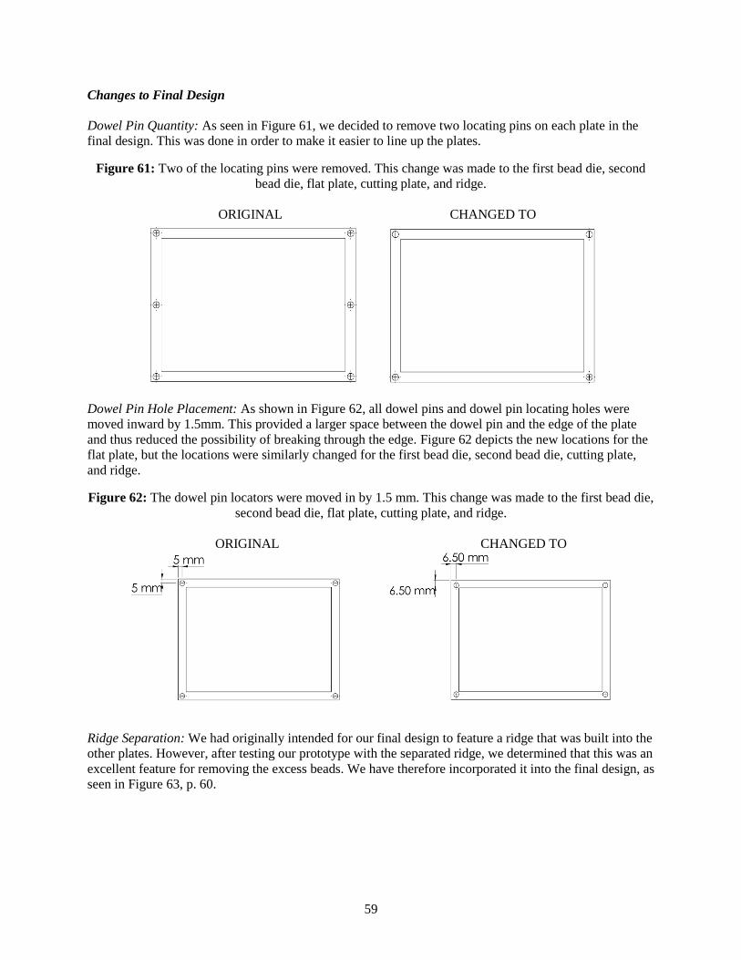
59
Changes to Final Design
Dowel Pin Quantity: As seen in Figure 61, we decided to remove two locating pins on each plate in the
final design. This was done in order to make it easier to line up the plates.
Figure 61: Two of the locating pins were removed. This change was made to the first bead die, second
bead die, flat plate, cutting plate, and ridge.
ORIGINAL CHANGED TO
Dowel Pin Hole Placement: As shown in Figure 62, all dowel pins and dowel pin locating holes were
moved inward by 1.5mm. This provided a larger space between the dowel pin and the edge of the plate
and thus reduced the possibility of breaking through the edge. Figure 62 depicts the new locations for the
flat plate, but the locations were similarly changed for the first bead die, second bead die, cutting plate,
and ridge.
Figure 62: The dowel pin locators were moved in by 1.5 mm. This change was made to the first bead die,
second bead die, flat plate, cutting plate, and ridge.
ORIGINAL CHANGED TO
Ridge Separation: We had originally intended for our final design to feature a ridge that was built into the
other plates. However, after testing our prototype with the separated ridge, we determined that this was an
excellent feature for removing the excess beads. We have therefore incorporated it into the final design, as
seen in Figure 63, p. 60.

60
Figure 63: The ridge was separated from the plates.
ORIGINAL CHANGED TO
Plate Thicknesses: We decided to change the thicknesses of the plates in order to make it easier to
machine them from stock aluminum sheets. The bead dies and flat plate were changed to be ¼ in (6.35
mm) high and the vacuum plate and cutting plate were changed to be ½ in (12.7 mm) high. The ridge was
also changed to be 0.121 in (3.07 mm) high (slightly less than 1.8 in) in order to provide more direct force
on the plastic from the heat press. An example of this change is shown in Figure 64.
Figure 64: The ridge was changed from 0.125 in high to 0.121 in high. This change was made in order to
increase the contact between the plastic and the plates.
ORIGINAL CHANGED TO
Vacuum Plate Hole Diameter: As seen in Figure 65, the diameter of the vacuum plate hole was changed
from 6.35 mm (0.25 in) to 6.91 mm (0.272 in) in order to accommodate the fitting we needed to use.
Figure 65: The diameter of the vacuum plate hole was changed from 6.35 mm (0.25 in) to 6.91 mm
(0.272 in) in order to accommodate the fitting we needed.
ORIGINAL CHANGED TO
Vacuum Plate Inner Edge: As shown in Figure 66, p. 61, the inner edge of the vacuum plate was removed
in order to stop it from blocking the bead holes above.

61
Figure 66: The inner edge of the vacuum plate was eliminated in order to stop it from interacting with the
bead holes on the plates above.
ORIGINAL CHANGED TO

62
Appendix C: Design Analysis Assignment
1. Material Selection Assignment – Functional Performance
Die Materials
Function Transfer the heat to the plastic tag material.
Constraints 350°C > Melting Temperature > 140 °C
Thermal Conductivity > 50 W/m °C
Objective Maximize Heat Transfer
Minimize Price
Figure 67: Plotted Price against Thermal Conductivity.
The top five materials choices for the die were: low alloy steel, low carbon steel, medium carbon steel,
age-hardening wrought aluminum alloys, and copper. Age-hardening wrought aluminum alloys was
chosen for the die material because it best maximized the heat transfer and minimized price.
Microtag Material
Function Hold beads
Constraints 350°C > Melting Temperature > 140 °C
Rated Excellent when in contact with 10% Hydrochloric acid
Objective Minimize Price

63
Figure 68: Plotted Price against Melting Temperature to determine material choices.
The top five material choices for the microtags were: PEEK, lead, Teflon, PET, and UHMW
Polyethylene. PEEK, with UHMWPE as an alternate, was chosen for the material of the microtags. This
decision was based on the compatible melting temperatures and approved for medical implantation, as the
tags could be coming into contact with bodily fluids during a surgery.
2. Material Section Assignment – Environmental Performance
The two materials that we decided between for our die material were aluminum and steel. The mass of
either of these materials needed in our final design is 3.4kg. For both aluminum and steel we found the
total mass of used raw materials, air emissions, water emissions, and solid waste. These values can be
found in Table 7 and a comparison graph can be found in Figure 69, p. 64.
Table 7: Total mass values for materials used, emissions, and waste for aluminum and steel.
Aluminum (g) Steel (g)
Raw 33659.64 2545.437
Air 20233.48 1649.622
Water 35.25587 414.9792
Waste 5497.265 0.0

64
Figure 69: Total mass values emissions for aluminum and steel.
After viewing the data in Figure 70, we have concluded aluminum has a bigger impact on the
environment than steel. Though steel is high in some categories, aluminum is at 100% in six categories
including: respiratory organics, climate change, radiation, ozone layer, acidification/eutrophication, and
minerals.
Figure 70: Relative impact of disaggregated damage categories for aluminum and steel.
Then if we compare aluminum and steel on EcoIndicator 99 point values, we can see that most important
damage category is minerals. This is seen in Figure 71, p. 64 and point values are specifically shown in
Figure 72, p. 65. From this we see that aluminum has the higher EcoIndicator 99 point value and most of
the points for aluminum come from mineral resource damage. Therefore aluminum has more
0
5000
10000
15000
20000
25000
30000
35000
40000
Raw Air Water Waste
Ma
ss (
g)
Al
Steel

65
environmental impact than steel. When considering the full life cycle, we found that aluminum continues
to have more environmental impact than steel. This is because aluminum parts wear out faster than steel
parts and must be replaced more often. This leads to more emissions since aluminum emissions are worse
than steel emissions. Although the environmental impact of aluminum is worse than steel, cost, thermal
conductivity, and machinability limit us to these two materials for our die material. Thus we would not
consider selecting a different material.
Figure 71: Normalized score of damage categories for aluminum and steel.
Figure 72: Single score comparison in points for aluminum and steel.
3. Manufacturing Process Selection Assignment
For the aluminum it was going to be used for the dies that we assume will need to be produced in a
volume of 100 for each die. Under this assumption that the sheets of aluminum used to produce the dies
of a non-circular prismatic shape, will range from 1/8 in. to ½ in, and the process will need to result in a

66
minimum tolerance of 0.01 mm. The manufacturing process to produce the dies would be Electric
Discharge Machining.
Figure 73: Potential manufacturing processes for Aluminum, produced from CES.
For the PEEK it was assumed that it would be purchased in sheets of a desired thickness and then the only
manufacturing process will be cutting it into the size needed to use within the dies. This would be done in
a volume of 100,000 and require an accuracy of a minimum of 0.01 mm. Only cutting process were
evaluated. To cut the PEEK we would recommend punching.
Figure 74: Potential manufacturing processes for cutting PEEK, produced from CES.

67
Appendix D: Additional Concepts
Concept: Injection-molded sheet with vacuum-held beads
This concept is very similar to Concept A (page 9), but involves injecting the plastic rather than using a
sheet melted by the heat press. The main advantage of this idea is that it will ensure that the same volume
of plastic is injected each time. This will allow our volume to be more accurate than if we used a sheet to
add plastic. The main disadvantages of this idea are: the increased complexity, the extra equipment that
would be necessary, and the possibility that the plastic would not cool uniformly. We would require
another piece of equipment to melt the plastic and would need to design a runner system to deliver it. We
would also need to address possible issues with non-uniform cooling of the plastic, which could cause
deformations or air pockets in the finished product. After the plastic cools, we would need to design a
method to cut it apart.
Concept: Layered plastic with suspended beads This concept would involve placing a shallow die inside the heat press and adding a thin layer of plastic
inside the die. Then it would be heated to its melting temperature and the first pair of beads would be
dropped into place. Next, another layer of plastic would be placed on top, and again it would be heated to
its melting temperature and the second pair of beads would be dropped into place. Lastly a final thin layer
of plastic would be added. This process would ensure that the beads are completely submerged in the
plastic and would be at no risk of falling out. However, there are a number of issues with this concept: the
extra equipment necessary to place the beads, the potential for the beads to move within the melted
plastic, and the extra time and effort needed to place and melt the many layers.
Figure 75: An illustration of Concept: Layered plastic with suspended beads.
Concept: Drill holes in plastic sheet for beads This concept would use a CNC drill press or similar machine to create tiny holes in a cool plastic sheet at
the bead placement sites. Beads would then be placed into the holes, covered with a thin plastic sheet, and
put into the heat press. Once the top plastic sheet melted enough to hold the beads in place, the process
would be repeated on the opposite side for the second pair of beads. This idea would require an extremely
accurate (and likely expensive) machine to drill or otherwise create holes in the plastic. It would also fail
to control whether or not all the beads were present in the holes before sealing them inside. However, this
idea allows the beads to become completely encased in plastic, which would prevent them from falling
out during use.
Concept: Robotic manufacturing
This concept uses a robot that has two arms, each with one plate of a heat press and each able to rotate
and move independently. Each heat press plate has thin through-holes that lead into a cavity for a
vacuum, similar to Concept A (page 9). The robots begin by dipping each vacuum plate into a container

68
of tungsten-carbide beads and sucking them by vacuum pressure into the shallow counter bores. The two
arms then bring the plates together on either side of a fixed sheet of plastic, using proximity sensors
affixed to each of the plates to ensure that proper bead spacing is maintained. The plates then heat up in
order to melt the beads into the plastic, and the vacuum turns off at a certain temperature to avoid
accidentally removing the beads. One of the plates has cutting ridges around the perimeter of each tag that
slice them apart. The plates then come apart, and the robotic arm flips over the bottom one to deposit the
finished tags into a container [4].
Concept: Double sheet forming using a vacuum and ridges This concept is a combination of Concepts A and C. Like Concept A, it uses a plastic sheet and die ridges
to separate the tags; like Concept C, it uses bead-holding dies both above and below the plastic. Thin
through holes drilled into each die are countersunk slightly for the tungsten carbide beads to fit into. The
beads are held in place using a vacuum system that lowers the pressure in cavities behind the through
holes. Similar to Concept A, beads are poured into each die, held in place by the vacuum, and melted into
a plastic sheet that’s placed in between the dies. Both layers of beads are installed at the same time using
the heat press, while cutting ridges on each die completely separate the tags under pressure. The plates
then come apart, the tags are allowed to cool, and then they are removed from the press. In this way, the
microtags would be cut apart as part of the heat press process.
Concept: Cavity forming
With this concept, the microtags would be formed separately by filling cavities instead of being cut out of
a sheet. A die with cylindrical cavities would be machined first. Then molten FDA-approved plastic
would be poured into the cavities. Like Concept C, it uses bead-holding dies both above and below the
plastic. Once solidified, the die would enter our heat press, The Geo Knight & Co., Inc. DC16AP, while
sandwiched in between the bead holding dies. Then with the tungsten carbide beads embedded into the
microtags in the correct orientation, the microtags could be punched out of the die.
Concept: Melting beads into surface In this concept, tungsten carbide beads would be melted into the top and bottom of a sheet of FDA-
approved plastic. The beads would be set in two bead-holding dies, one above and one below. The sheet
of FDA-approved plastic would be sandwiched in between these bead-holding dies and put into our heat
press. Afterwards, the sheet would be diced into a number of produced microtags.
Concept: Melting beads into interior In this concept, tungsten carbide beads would be melted into a sheet of FDA-approved plastic. The beads
would be set in two bead-holding dies, one above and one below, where the beads would sit on pedestals
that would go into the FDA-approved plastic sheet. The sheet of FDA-approved plastic would be
sandwiched in between these bead-holding dies and put into our heat press. During the process, the beads
would be melted into the interior of the FDA-approved plastic. Afterwards, the sheet would be diced into
a number of produced microtags.
Concept: Melting beads into interior from above In this concept, tungsten carbide beads would be melted into a sheet of FDA-approved plastic. The beads
would be set into a bead-holding die where the beads would sit on pedestals at different heights that
would go into the FDA-approved plastic sheet. The sheet of FDA-approved plastic would be set into our
heat press with the bead-holding die above and in between the sheet and heat press. During the process,
the beads would be melted into the interior through the top of the FDA-approved plastic. Afterwards, the
sheet would be diced into a number of produced microtags.

69
Concept: Using molten plastic to surround beads and solidify This concept, instead of using our heat press, would form our microtags using a molten FDA-approved
plastic that would solidify around an already set bead orientation. A die would be machined that would
have numerous pedestals to create the desired bead orientation. Once the beads would be set in the die,
the molten FDA-approved plastic would be poured into the die. Either letting the die cool or freezing it,
the FDA-approved plastic would solidify, the sheet would be removed from the die, and the sheet could
be then diced into a number of produced microtags.
Concept: Using molten plastic to surround shape or interior skeleton This concept, instead of using our heat press, would form our microtags using a molten FDA-approved
plastic that would solidify around a tungsten carbide coil or an interior skeleton that would create a set
bead orientation. The tungsten carbide coils or interior bead holding skeletons would be placed in the die
and the molten FDA-approved plastic would be poured into the die. Either letting the die cool or freezing
it, the FDA-approved plastic would solidify, the sheet would be removed from the die, and the sheet could
be then diced into a number of produced microtags.
Concept: Hinged die This concept includes two dies that have a hinge so that they maintain the correct alignment with each
other (Figure 76). One of the dies is molded so there are hard stops, and the other die has a vacuum
attached to it that helps hold the beads in position. With heat and pressure applied to the plastic that is
placed in between the dies, the plastic will melt and conform to the shape of the die with the beads inside
of it. After cooling the sheet can be removed and cut into the proper size.
Figure 76: Drawing of Concept: Hinged die.
Concept: Assembly line bead imbedding
This concept uses a manufacturing line type of approach, Figure 77, p.70. First it would use multiple
drills to cut holes into the plastic. Each hole would go to the specific distance needed for the bead to be
positioned correctly. After drilling, a tube will precisely drop a bead in each hole. Followed by that,
another tube will fill the rest of the hole with molten plastic to seal it. Ideally there would be a large
“assembly line” of these tools to help move the process along quickly

70
Figure 77: Illustration of Assembly line bead imbedding.
Concept: Welding or Ultrasonic waves
This approach does not use a heat press at all. Instead, it just uses a press to make indents in the plastic
large enough for the beads to rest in, Figure 78. Once the indents are made, a bead will be positioned in it,
and a laser beam (or concentrated ultrasonic wave) would be directed to the bead to heat it up. The bead
would heat up and start to melt through the plastic. Using different heating time one could make sure that
it is melted to a certain depth in the material.
Figure 78: Picture of Welding or ultrasonic waves.
Concept: Spring loaded bead insertion
This concept starts off by heating the plastic up. This could be done by moving the plastic down a
conveyor belt that is heated. After the plastic is malleable, it would pass under a spring loaded bead gun.
Different bead guns would have different springs in them to make sure that the proper depth would be
maintained. These guns would also have a high degree of accuracy to ensure that the proper orientation of
the beads is maintained, Figure 79, p. 71

71
Figure 79: Illustration of spring loaded bead insertion.
Concept: Interlocking triangles This design is most similar to Concept D, with the exception that two different styles of triangles are
formed, rather than a single shape. The first triangle would have a cutaway near the center so that the
second triangle could fit into it. Each triangle design would be built using its own die, with the beads
placed at the bottom of the die, each shape then filled with liquid plastic, before covering it with a flat
plate and melted. The triangles with a hole through it would not be fully melted, before inserting a semi-
cooled I-triangle through the whole and turning, so that the triangles are interlocked and possibly melted
together as they finish cooling. The shapes of the triangles and the final tags are shown in Figure 80, p.71.
Figure 80: Interlocking triangles.
Concept: Plastic beads and cube breakers This design is constructed using a single die that is constructed slightly larger than the desired size of the
beads, to account for the type of plastic being used. At the bottom of the die the beads supported by a
vacuum. The die is then filled with plastic beads, before a flat plate is aligned to the top of the die using
dowel pins. The configuration is then melted using a heat press. The plastic is given a significant time to
cool until it can be removed as a single block. After removing the block, the die is refilled with beads
before reinserting the block after rotating it over and then by 180°. The top plate is then realigned with

72
dowels pins before using the heat press to melt the plastic again. Once the plastic has had sufficient time
to cool, the block is removed and broken, helped by the points that are included in the shape.
Figure 81: Plastic beads with cubes.
Concept: Form around bead holder
This design is based off of having an outside manufactured holder for the beads that is then placed in a die
with individual cubes of the correct size. Metal beads are placed in each holder before plastic beads are
used to fill each of the cubes within the die. A flat plate is then used to cover the die before the plastic is
melted using a heat press. After time is allowed for the plastic to cool, the cubes are punched out. The
bead holder and cross section of the die are shown in Figure 82.
Figure 82: Form around holder.
Concept: Spherical halves This design would involve having two dies. One die would contain half spheres with places to hold three
of the beads and the second die would contain half spheres with places to hold a single bead at the
bottom. The metal beads would be added to the dies, before the dies would be filled with plastic beads. A
flat plat would be placed over the two dies and they would be melted side-by-side using the heat press.
After a little time to cool, the die with single beads at the bottom would be turned over and aligned with
the other die before using the heat press to melt the two together. Additional plastic beads may be added
to the bottom die if there are significant plastic vacancies. After time is allowed for cooling, the spherical
tags would be removed from the die. The half spheres and final tag are shown in Figure 83, p.73.

73
Figure 83: Spherical halves.

74
Appendix E: Biographies
Brian Arntfield
Brian Arntfield was born and raised in Michigan in the Macomb county area. When he was younger, he
always wanted to help his dad, who rented out houses, with anything and everything that needed to be
done with the rental houses. These tasks ranged from roofing, patching walls, installing hardwood floor,
to fixing/installing appliances, and everything in between. All of the handyman type of work that he did
sparked an interest in figuring out how things work and a love for building things. Brian became
interested in renewable energy projects, and after building 2 solar panels and water-proof cases to go with
them, he realized that a lot of his interests lined up well with engineering. Brian likes working with his
hands, and decided that Mechanical Engineering would be the best way to be able to be hands on. He
plans on working in engineering, and after he has some experience he wants to work towards an MBA
and become a manager for an engineering based company.
In California on top of an aircraft carrier, which was retired and
turned into a museum, inside a helicopter
Kristine Kruppa Kristine Kruppa is from a small house in Livonia, Michigan where she lives with her mother, father, three
younger brothers, and four cats. She came to the University of Michigan to study Mechanical Engineering
after being encouraged by three of her uncles, who hold degrees in the same field. Her decision was also
based on her fascination with heavy machinery and complex mechanical systems.
This past summer Kristine interned at Ford Motor Company’s Michigan Assembly Plant, where she
helped to launch the 2013 Focus Electric, Focus ST and C-max. The experience left her with an enormous
amount of respect for the automotive industry and the strong desire to purchase a Ford.

75
Examining a new vehicle modification on the Ford Focus
Kristine intends to graduate in May and spend the subsequent month fulfilling her dream to travel
overseas and ride trains around Europe. After that, she will begin work at an as-yet-unknown company.
She plans to attend school part-time while working and eventually complete either an MBA or advanced
engineering degree. Her long-term goals include an interesting job, a Master’s degree, and trips to strange
and exotic countries.
Michelle Pascual
Michelle Pascual grew up in the Big Sky Country of Bozeman, Montana. She got to experience the joys
of nature by annually visiting Yellowstone or Glacier National Park. The thing she misses most about
home is Montana Moose Moss ice cream and hiking through the snow to cut down a Christmas tree. From
a young age she developed an interest in automobiles, which ultimately led her to pursue a degree in
mechanical engineering. She would be ecstatic to own or drive an Audi R8, but she would settle for a
Mini Cooper S. In the future she hopes to work for an automotive supply company, gain a masters in
industrial and operations engineering, and hopefully have the opportunity to work overseas for a period of
time.
Enjoying the cab of a train
Mackenzie Wilson
Mackenzie Wilson is a senior in Mechanical Engineering from Tampa, FL. Mackenzie’s interest in
Mechanical Engineering stems from his love for problem solving, working in hands on environments, and
the desire to work in the development of innovative technology. His future plans include graduating,
finding a job in Mechanical Engineering that he will be happy in, getting a master’s degree in Mechanical
Engineering and maybe a MBA, and becoming a Professional Engineer.

76
Before coming to Michigan he had never lived outside of Florida but loves traveling and seeing new
places. He left Florida and came to Michigan because he was tired of hurricanes and I wanted all four
seasons. He loves eating sushi and has an unhealthy relationship with ESPN. He has no preference in
where he lives after college but if he is close to the University of Michigan, he’d be happy.
Standing with Navy statue at the end of the Golden Gate Bridge in San Francisco

77
Appendix F: Gantt Chart

78
Appendix G: Design Safe Hazard Analysis