measurement of alpha and neutron decay widths of excited...
TRANSCRIPT
University of Birmingham
Measurement of alpha and neutron decay widths ofexcited states of C-14Haigh, PJ; Ashwood, Nicholas; Bloxham, T; Curtis, Neil; Freer, Martin; McEwan, P; Price, DC;Ziman, Victor; Bohlen, HG; Kokalova, Tz; Schulz, Ch; Torabi, R; von Oertzen, W; Wheldon,Carl; Catford, W; Harlin, C; Kalpakchieva, R; Massey, TNDOI:10.1103/PhysRevC.78.014319
Document VersionPublisher's PDF, also known as Version of record
Citation for published version (Harvard):Haigh, PJ, Ashwood, N, Bloxham, T, Curtis, N, Freer, M, McEwan, P, Price, DC, Ziman, V, Bohlen, HG,Kokalova, T, Schulz, C, Torabi, R, von Oertzen, W, Wheldon, C, Catford, W, Harlin, C, Kalpakchieva, R &Massey, TN 2008, 'Measurement of alpha and neutron decay widths of excited states of C-14', Physical ReviewC, vol. 78, no. 1, pp. 1-14. https://doi.org/10.1103/PhysRevC.78.014319
Link to publication on Research at Birmingham portal
General rightsUnless a licence is specified above, all rights (including copyright and moral rights) in this document are retained by the authors and/or thecopyright holders. The express permission of the copyright holder must be obtained for any use of this material other than for purposespermitted by law.
•Users may freely distribute the URL that is used to identify this publication.•Users may download and/or print one copy of the publication from the University of Birmingham research portal for the purpose of privatestudy or non-commercial research.•User may use extracts from the document in line with the concept of ‘fair dealing’ under the Copyright, Designs and Patents Act 1988 (?)•Users may not further distribute the material nor use it for the purposes of commercial gain.
Where a licence is displayed above, please note the terms and conditions of the licence govern your use of this document.
When citing, please reference the published version.
Take down policyWhile the University of Birmingham exercises care and attention in making items available there are rare occasions when an item has beenuploaded in error or has been deemed to be commercially or otherwise sensitive.
If you believe that this is the case for this document, please contact [email protected] providing details and we will remove access tothe work immediately and investigate.
Download date: 06. Jan. 2020

PHYSICAL REVIEW C 78, 014319 (2008)
Measurement of α and neutron decay widths of excited states of 14C
P. J. Haigh,1,* N. I. Ashwood,1 T. Bloxham,1 N. Curtis,1 M. Freer,1 P. McEwan,1 D. Price,1 V. Ziman,1 H. G. Bohlen,2
Tz. Kokalova,2 Ch. Schulz,2 R. Torabi,2 W. von Oertzen,2 C. Wheldon,2 W. Catford,3 C. Harlin,3
R. Kalpakchieva,4 and T. N. Massey5
1School of Physics and Astronomy, University of Birmingham, Edgbaston, Birmingham, B15 2TT, United Kingdom2Hahn-Meitner-Institut, Glienicker Strasse 100, D-14109 Berlin, Germany
3The School of Electronics and Physical Sciences, University of Surrey, Guildford, Surrey, GU2 7XH, United Kingdom4Flerov Laboratory, JINR, RU-141980 Dubna, Russia
5Department of Physics and Astronomy, Ohio University, Athens, Ohio 45701-2979, USA(Received 13 February 2008; published 25 July 2008)
The 12C(16O,14O)14C reaction was studied at a beam energy of 234 MeV. The 14O ejectile was detected by aQ3D spectrometer at forward angles. The energies and angles of the excited 14C recoil break-up fragments weremeasured in coincidence with the 14O ejectile using a double sided silicon strip detector array at backward angles.A complete kinematic reconstruction of the reaction was performed to reconstruct the 14C∗ → 10Be + α and14C∗ → 13C + n decay channels and the branching ratios and widths of these decays were calculated. Theoreticaldecay branches were calculated using barrier penetrability factors and were compared to the measured ratios toprovide information on the spins, parities, and configurations of the states. Neutron emission was found to befavored for the 11.73, 12.96, 14.87, 16.72, and 18.6 MeV states. The 14.87, 18.6, and 21.4 MeV states werefound to have a considerable width for α-decay and are candidates for the three bodied molecular cluster structureof 14C.
DOI: 10.1103/PhysRevC.78.014319 PACS number(s): 21.10.Tg, 21.60.Gx, 23.60.+e, 27.20.+n
I. INTRODUCTION
It is well known that 8Be has a well developed α-αcluster structure [1,2]. The 8Be nucleus is unstable as the α-αinteraction is weak and has a repulsive core due to the Pauliprinciple. However, the addition of a neutron produces enoughbinding energy to make the 9Be nucleus stable. The bindingenergy which stabilizes the system is provided by the neutronwhich resides in delocalized orbits around the α-cores. In thecase of 10Be, linear combinations of the two valence neutronorbitals produce π - and σ -bonds which bind the dimer core [3].There is now strong evidence for these molecular-like α-cluster structures in 9,10Be [4–10]. Antisymmetrized moleculardynamics (AMD) calculations provide further support forthese molecular structures in 9−12Be; where they reproducethese molecular characteristics despite the fact that no explicitcluster content is assumed [3,11–16].
These concepts can be extended to the neutron-rich carbonisotopes, in which the core has a three α-particle clusterconfiguration. Again, the valence neutrons would reside indelocalised molecular orbits around the cores and wouldincrease the binding energy and stability of the system. Theseideas have been explored extensively by Milin and von Oertzenet al., in which the complete spectroscopy of 13C [17] and14C [18] states were examined. In this method, the single-particle shell-model states are eliminated and the remainingstates are assigned to rotational bands associated with prolate,linear-chain structures and oblate, triangular configurations.In 14C, three different molecular cluster configurations canbe expected: triangular configurations with the neutrons in
σ -bonds between two of the α-particles, linear reflection-symmetric chains in which the valence neutrons are equallydistributed among the three α-cores (α-n-α-n-α) and linearintrinsically reflection-asymmetric configurations in which thetwo neutrons reside between two of the α-cores (α-2n-α-α).This final configuration gives rise to parity inversion doublets.
These proposed molecular configurations should exhibitstrong α-decay. Here we present measurements of the neutronand α-decay branching ratios associated with highly excitedstates in 14C. The experimentally determined branching ratiosare compared with theoretical decay branches to provideinformation on the spins, parities, and configurations of thesestates. Additional information on the widths and population ofthe states, which depend on dynamical matching conditions,are used to help indicate their properties.
II. EXPERIMENTAL PROCEDURE
The two-neutron transfer reaction 12C(16O,14O)14C wasstudied at a beam energy of 234 MeV, in two separatemeasurements, at the Ionen-Strahl-Labor (ISL) facility, atthe Hahn-Meitner-Institut (HMI), Berlin. This reaction hasa ground state Q-value of Q0 = −15.763 MeV. In the first setof measurements the beam was incident on a 200 µg cm−212Ctarget and in the second the target used was a 20 µg cm−212Cfoil.
The measurements were performed with a Q3D magneticspectrometer [19–21] and an array of charged particle detec-tors. The 14O ejectile was identified in the Q3D focal planedetector using proportional wires for energy loss and a plasticscintillator to measure time of flight and total energy. Theposition of the 14O along the focal plane was measured usingthe delay-line read-out technique. The 14O nucleus has no
0556-2813/2008/78(1)/014319(14) 014319-1 ©2008 The American Physical Society
P. J. HAIGH et al. PHYSICAL REVIEW C 78, 014319 (2008)
4 6 8 10 12 14 16 18 20 22 24 26 28Excitation Energy in 14C (MeV)
0
500
1000
1500
Cou
nts
per
100
keV
6.73
(a)
7.34
8.32
9.80
10.7
4
12C(16O,14O)14CEL = 234 MeVθL = 6.5o-9.5o
11.7
3
12.9
614
.114
.87
15.7
516
.72
17.5
18.6
19.8
21.4
10 12 14 16 18 20 22 24 26 28 30Excitation Energy in 14C (MeV)
0
50
100
150
Cou
nts
per
50 k
eV
11.7
3
(b)
12.9
6
14.8
7 12C(16O,14O)14C
16.7
2
EL = 234 MeVθL = 8.5o-11.5o
18.6 21
.4
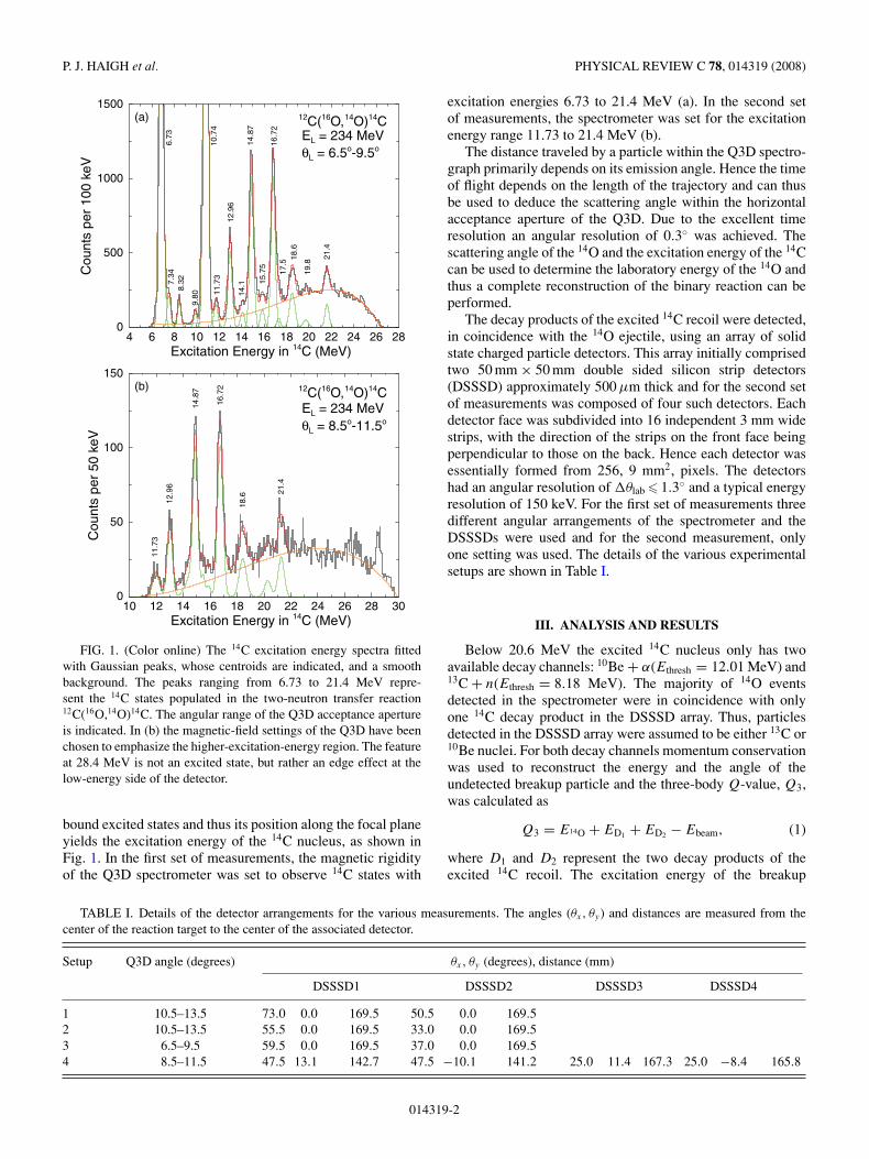
FIG. 1. (Color online) The 14C excitation energy spectra fittedwith Gaussian peaks, whose centroids are indicated, and a smoothbackground. The peaks ranging from 6.73 to 21.4 MeV repre-sent the 14C states populated in the two-neutron transfer reaction12C(16O,14O)14C. The angular range of the Q3D acceptance apertureis indicated. In (b) the magnetic-field settings of the Q3D have beenchosen to emphasize the higher-excitation-energy region. The featureat 28.4 MeV is not an excited state, but rather an edge effect at thelow-energy side of the detector.
bound excited states and thus its position along the focal planeyields the excitation energy of the 14C nucleus, as shown inFig. 1. In the first set of measurements, the magnetic rigidityof the Q3D spectrometer was set to observe 14C states with
excitation energies 6.73 to 21.4 MeV (a). In the second setof measurements, the spectrometer was set for the excitationenergy range 11.73 to 21.4 MeV (b).
The distance traveled by a particle within the Q3D spectro-graph primarily depends on its emission angle. Hence the timeof flight depends on the length of the trajectory and can thusbe used to deduce the scattering angle within the horizontalacceptance aperture of the Q3D. Due to the excellent timeresolution an angular resolution of 0.3◦ was achieved. Thescattering angle of the 14O and the excitation energy of the 14Ccan be used to determine the laboratory energy of the 14O andthus a complete reconstruction of the binary reaction can beperformed.
The decay products of the excited 14C recoil were detected,in coincidence with the 14O ejectile, using an array of solidstate charged particle detectors. This array initially comprisedtwo 50 mm × 50 mm double sided silicon strip detectors(DSSSD) approximately 500 µm thick and for the second setof measurements was composed of four such detectors. Eachdetector face was subdivided into 16 independent 3 mm widestrips, with the direction of the strips on the front face beingperpendicular to those on the back. Hence each detector wasessentially formed from 256, 9 mm2, pixels. The detectorshad an angular resolution of �θlab � 1.3◦ and a typical energyresolution of 150 keV. For the first set of measurements threedifferent angular arrangements of the spectrometer and theDSSSDs were used and for the second measurement, onlyone setting was used. The details of the various experimentalsetups are shown in Table I.
III. ANALYSIS AND RESULTS
Below 20.6 MeV the excited 14C nucleus only has twoavailable decay channels: 10Be + α(Ethresh = 12.01 MeV) and13C + n(Ethresh = 8.18 MeV). The majority of 14O eventsdetected in the spectrometer were in coincidence with onlyone 14C decay product in the DSSSD array. Thus, particlesdetected in the DSSSD array were assumed to be either 13C or10Be nuclei. For both decay channels momentum conservationwas used to reconstruct the energy and the angle of theundetected breakup particle and the three-body Q-value, Q3,was calculated as
Q3 = E14O + ED1 + ED2 − Ebeam, (1)
where D1 and D2 represent the two decay products of theexcited 14C recoil. The excitation energy of the breakup
TABLE I. Details of the detector arrangements for the various measurements. The angles (θx, θy) and distances are measured from thecenter of the reaction target to the center of the associated detector.
Setup Q3D angle (degrees) θx, θy (degrees), distance (mm)
DSSSD1 DSSSD2 DSSSD3 DSSSD4
1 10.5–13.5 73.0 0.0 169.5 50.5 0.0 169.52 10.5–13.5 55.5 0.0 169.5 33.0 0.0 169.53 6.5–9.5 59.5 0.0 169.5 37.0 0.0 169.54 8.5–11.5 47.5 13.1 142.7 47.5 −10.1 141.2 25.0 11.4 167.3 25.0 −8.4 165.8
014319-2
MEASUREMENT OF α AND NEUTRON DECAY . . . PHYSICAL REVIEW C 78, 014319 (2008)
fragments was calculated by comparing Q3 with the three-body Q-value in which the decay products are produced intheir ground states, Q30 :
Ex(D1,2) = |Q30 − Q3|. (2)
In each decay channel only one of the daughter nuclei can bein an excited state, as the first excited state of an α particle is20.2 MeV. Thus, the excitation energy of the breakup frag-ments corresponds to the excitation energy of either the 13C orthe 10Be. So, for example, the detection of a 10Be nucleus withEx(10Be) = 3.368 MeV corresponds to the 14C∗α-decaying tothe first excited state of 10Be.
The various decay channels were analyzed using MonteCarlo simulations of the reaction and detection processes. Thesimulations reproduce the experimental acceptances and smearthe energies and angles in accordance with the experimentalresolutions. The outputs of the simulations were subsequentlyprocessed as if they were real events using the same analysisprocedures as those used for the experimental data. Thesesimulations permitted the theoretical peak line-shapes in thedecay products excitation energy spectra to be reconstructed.These line-shapes were normalized to fit the experimentaldata and the integrated area of the line-shapes were comparedwith the number of counts in the associated state in the Q3D,14C, excitation energy spectrum, in order to deduce branchingratios.
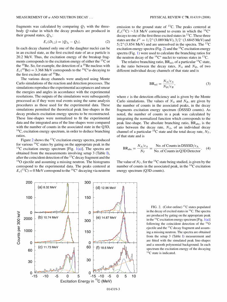
Figure 2 shows the 13C excitation energy spectra, producedfor various 14C states by gating on the appropriate peak in the14C excitation energy spectrum [Fig. 1(a)]. The spectra areobtained from the measurements involving setup 3 (Table I),after the coincident detection of the 13C decay fragment and the14O ejectile and assuming a missing neutron. The histogramscorrespond to the experimental data. The peaks centered atEx(13C) = 0 MeV correspond to the 14C∗ decaying via neutron
emission to the ground state of 13C. The peaks centered atEx(13C) ∼3.8 MeV correspond to events in which the 14C∗decays to one of the first three excited states in 13C. These threestates are the Jπ = 1/2+(3.089 MeV), 3/2−(3.6845 MeV) and5/2+(3.854 MeV) and are unresolved in the spectra. The 13Cexcitation energy spectra (Fig. 2) and the 14C excitation energyspectra (Fig. 1) were used to calculate the branching ratios forthe neutron decay of the 14C∗ nuclei to various states in 13C.
The relative branching ratio, BRrel, of a particular 14C state,is the ratio between the decay rates, NA and NB , of twodifferent individual decay channels of that state and is
BRrel = NA/εA
NB/εB
, (3)
where ε is the detection efficiency and is given by the MonteCarlo simulations. The values of NA and NB , are given bythe number of counts in the associated peaks, in the decayfragments excitation energy spectrum (DSSSD counts). Asnoted, the number of counts in a peak was calculated byintegrating the normalized function which corresponds to thepeak line-shape. The absolute branching ratio, BRabs, is theratio between the decay rate, NA, of an individual decaychannel of a particular 14C state and the total decay rate, NT ,of that state and is
BRabs = NA/εA
NT
= No. of Counts in DSSSD/εA
No. of Counts in Q3D Detector. (4)
The value of NT , for the 14C state being studied, is given by thenumber of counts in the associated peak, in the 14C excitationenergy spectrum (Q3D counts).
-15 -10 -5 0 513
C (MeV)
0
30
60
0
1000
2000
Cou
nts
per
300
keV 0
100
200
-15 -10 -5 0 5 100
30
600
150
300
0
150
300(a) 8.32 MeV
(b) 10.74 MeV
(c) 11.73 MeV
(d) 12.96 MeV
(e) 14.87 MeV
(f) 18.6 MeV
Excitation Energy in
FIG. 2. (Color online) 13C states populatedin the decay of excited states in 14C. The spectraare produced by gating on the appropriate peakin the 14C excitation energy spectrum [Fig. 1(a)]following the coincident detection of the 14Oejectile and the 13C decay fragment and assum-ing a missing neutron. The spectra are obtainedfrom the setup 3 (Table I) measurement andare fitted with the simulated peak line-shapesand a smooth polynomial background. In eachspectrum the excitation energy of the decaying14C state is indicated.
014319-3
P. J. HAIGH et al. PHYSICAL REVIEW C 78, 014319 (2008)
(a) (b)
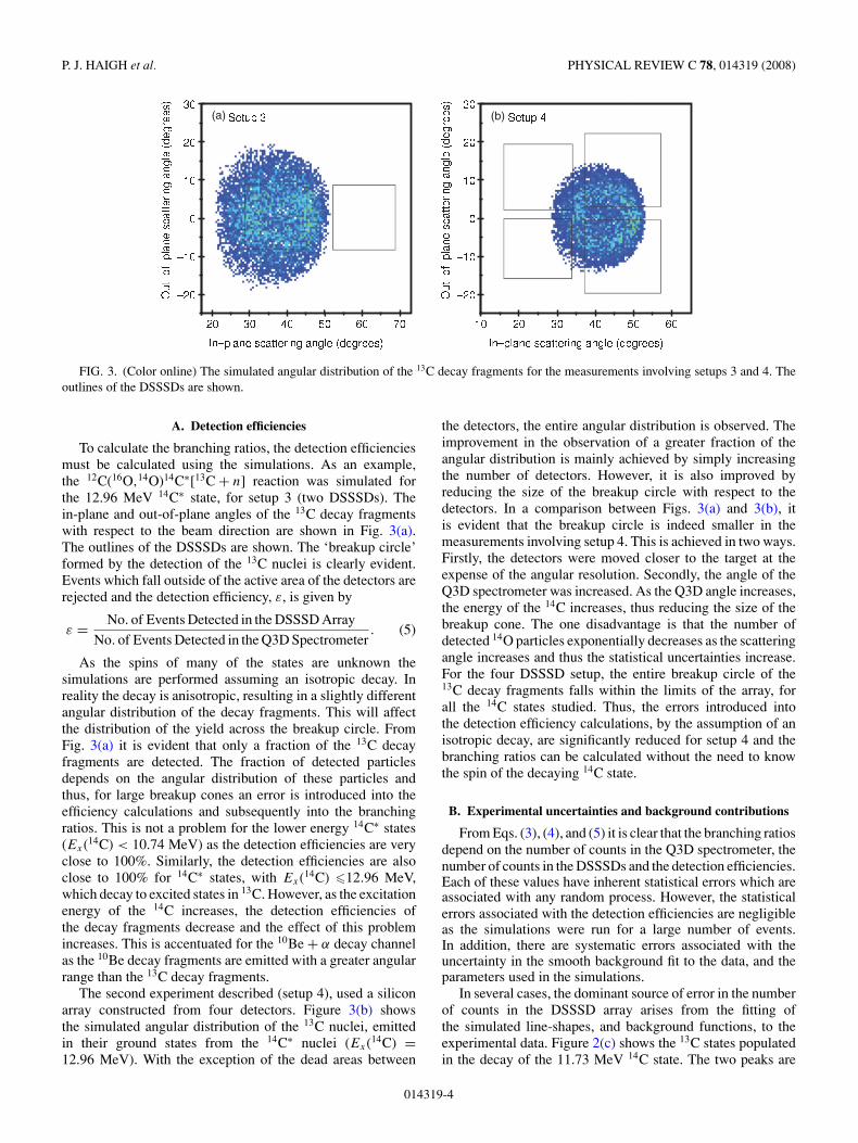
FIG. 3. (Color online) The simulated angular distribution of the 13C decay fragments for the measurements involving setups 3 and 4. Theoutlines of the DSSSDs are shown.
A. Detection efficiencies
To calculate the branching ratios, the detection efficienciesmust be calculated using the simulations. As an example,the 12C(16O,14O)14C∗[13C + n] reaction was simulated forthe 12.96 MeV 14C∗ state, for setup 3 (two DSSSDs). Thein-plane and out-of-plane angles of the 13C decay fragmentswith respect to the beam direction are shown in Fig. 3(a).The outlines of the DSSSDs are shown. The ‘breakup circle’formed by the detection of the 13C nuclei is clearly evident.Events which fall outside of the active area of the detectors arerejected and the detection efficiency, ε, is given by
ε = No. of Events Detected in the DSSSD Array
No. of Events Detected in the Q3D Spectrometer. (5)
As the spins of many of the states are unknown thesimulations are performed assuming an isotropic decay. Inreality the decay is anisotropic, resulting in a slightly differentangular distribution of the decay fragments. This will affectthe distribution of the yield across the breakup circle. FromFig. 3(a) it is evident that only a fraction of the 13C decayfragments are detected. The fraction of detected particlesdepends on the angular distribution of these particles andthus, for large breakup cones an error is introduced into theefficiency calculations and subsequently into the branchingratios. This is not a problem for the lower energy 14C∗ states(Ex(14C) < 10.74 MeV) as the detection efficiencies are veryclose to 100%. Similarly, the detection efficiencies are alsoclose to 100% for 14C∗ states, with Ex(14C) �12.96 MeV,which decay to excited states in 13C. However, as the excitationenergy of the 14C increases, the detection efficiencies ofthe decay fragments decrease and the effect of this problemincreases. This is accentuated for the 10Be + α decay channelas the 10Be decay fragments are emitted with a greater angularrange than the 13C decay fragments.
The second experiment described (setup 4), used a siliconarray constructed from four detectors. Figure 3(b) showsthe simulated angular distribution of the 13C nuclei, emittedin their ground states from the 14C∗ nuclei (Ex(14C) =12.96 MeV). With the exception of the dead areas between
the detectors, the entire angular distribution is observed. Theimprovement in the observation of a greater fraction of theangular distribution is mainly achieved by simply increasingthe number of detectors. However, it is also improved byreducing the size of the breakup circle with respect to thedetectors. In a comparison between Figs. 3(a) and 3(b), itis evident that the breakup circle is indeed smaller in themeasurements involving setup 4. This is achieved in two ways.Firstly, the detectors were moved closer to the target at theexpense of the angular resolution. Secondly, the angle of theQ3D spectrometer was increased. As the Q3D angle increases,the energy of the 14C increases, thus reducing the size of thebreakup cone. The one disadvantage is that the number ofdetected 14O particles exponentially decreases as the scatteringangle increases and thus the statistical uncertainties increase.For the four DSSSD setup, the entire breakup circle of the13C decay fragments falls within the limits of the array, forall the 14C states studied. Thus, the errors introduced intothe detection efficiency calculations, by the assumption of anisotropic decay, are significantly reduced for setup 4 and thebranching ratios can be calculated without the need to knowthe spin of the decaying 14C state.
B. Experimental uncertainties and background contributions
From Eqs. (3), (4), and (5) it is clear that the branching ratiosdepend on the number of counts in the Q3D spectrometer, thenumber of counts in the DSSSDs and the detection efficiencies.Each of these values have inherent statistical errors which areassociated with any random process. However, the statisticalerrors associated with the detection efficiencies are negligibleas the simulations were run for a large number of events.In addition, there are systematic errors associated with theuncertainty in the smooth background fit to the data, and theparameters used in the simulations.
In several cases, the dominant source of error in the numberof counts in the DSSSD array arises from the fitting ofthe simulated line-shapes, and background functions, to theexperimental data. Figure 2(c) shows the 13C states populatedin the decay of the 11.73 MeV 14C state. The two peaks are
014319-4
MEASUREMENT OF α AND NEUTRON DECAY . . . PHYSICAL REVIEW C 78, 014319 (2008)
-15 -10 -5 0 5 10
Excitation Energy in 13C (MeV)
0
20
40
60
Cou
nts
per
300
keV
0
20
40
60 (a)
(b)
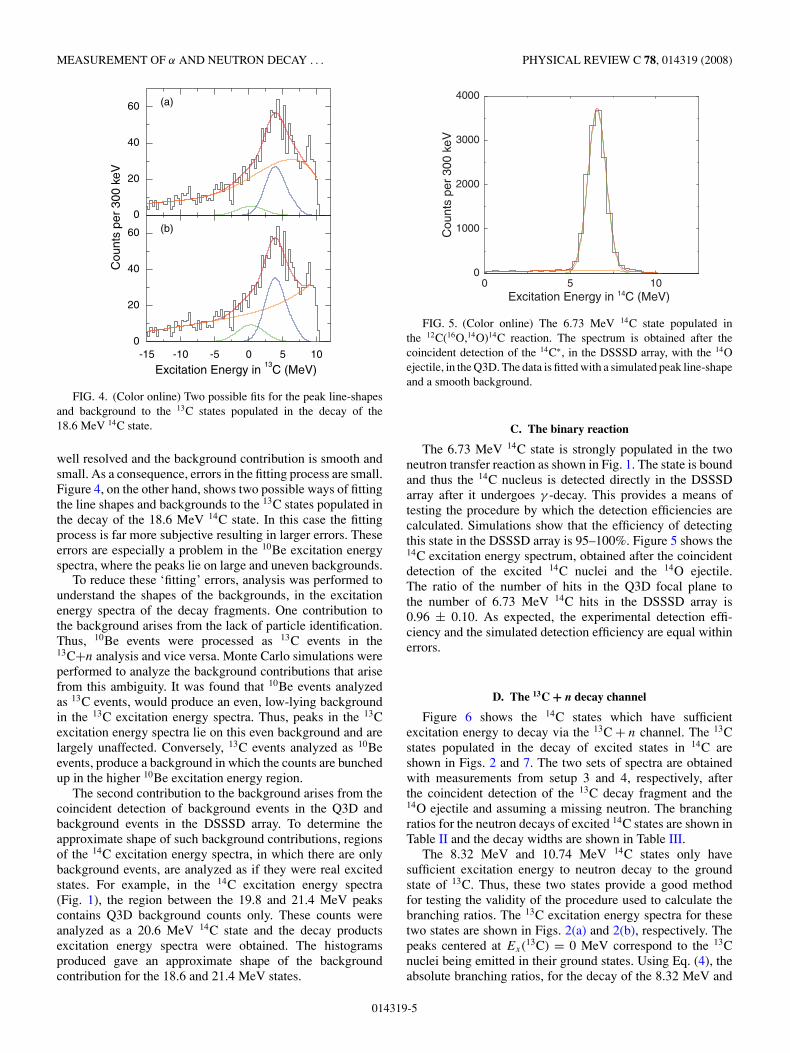
FIG. 4. (Color online) Two possible fits for the peak line-shapesand background to the 13C states populated in the decay of the18.6 MeV 14C state.
well resolved and the background contribution is smooth andsmall. As a consequence, errors in the fitting process are small.Figure 4, on the other hand, shows two possible ways of fittingthe line shapes and backgrounds to the 13C states populated inthe decay of the 18.6 MeV 14C state. In this case the fittingprocess is far more subjective resulting in larger errors. Theseerrors are especially a problem in the 10Be excitation energyspectra, where the peaks lie on large and uneven backgrounds.
To reduce these ‘fitting’ errors, analysis was performed tounderstand the shapes of the backgrounds, in the excitationenergy spectra of the decay fragments. One contribution tothe background arises from the lack of particle identification.Thus, 10Be events were processed as 13C events in the13C+n analysis and vice versa. Monte Carlo simulations wereperformed to analyze the background contributions that arisefrom this ambiguity. It was found that 10Be events analyzedas 13C events, would produce an even, low-lying backgroundin the 13C excitation energy spectra. Thus, peaks in the 13Cexcitation energy spectra lie on this even background and arelargely unaffected. Conversely, 13C events analyzed as 10Beevents, produce a background in which the counts are bunchedup in the higher 10Be excitation energy region.
The second contribution to the background arises from thecoincident detection of background events in the Q3D andbackground events in the DSSSD array. To determine theapproximate shape of such background contributions, regionsof the 14C excitation energy spectra, in which there are onlybackground events, are analyzed as if they were real excitedstates. For example, in the 14C excitation energy spectra(Fig. 1), the region between the 19.8 and 21.4 MeV peakscontains Q3D background counts only. These counts wereanalyzed as a 20.6 MeV 14C state and the decay productsexcitation energy spectra were obtained. The histogramsproduced gave an approximate shape of the backgroundcontribution for the 18.6 and 21.4 MeV states.
0 5 10Excitation Energy in 14C (MeV)
0
1000
2000
3000
4000
Cou
nts
per
300
keV
FIG. 5. (Color online) The 6.73 MeV 14C state populated inthe 12C(16O,14O)14C reaction. The spectrum is obtained after thecoincident detection of the 14C∗, in the DSSSD array, with the 14Oejectile, in the Q3D. The data is fitted with a simulated peak line-shapeand a smooth background.
C. The binary reaction
The 6.73 MeV 14C state is strongly populated in the twoneutron transfer reaction as shown in Fig. 1. The state is boundand thus the 14C nucleus is detected directly in the DSSSDarray after it undergoes γ -decay. This provides a means oftesting the procedure by which the detection efficiencies arecalculated. Simulations show that the efficiency of detectingthis state in the DSSSD array is 95–100%. Figure 5 shows the14C excitation energy spectrum, obtained after the coincidentdetection of the excited 14C nuclei and the 14O ejectile.The ratio of the number of hits in the Q3D focal plane tothe number of 6.73 MeV 14C hits in the DSSSD array is0.96 ± 0.10. As expected, the experimental detection effi-ciency and the simulated detection efficiency are equal withinerrors.
D. The 13C + n decay channel
Figure 6 shows the 14C states which have sufficientexcitation energy to decay via the 13C + n channel. The 13Cstates populated in the decay of excited states in 14C areshown in Figs. 2 and 7. The two sets of spectra are obtainedwith measurements from setup 3 and 4, respectively, afterthe coincident detection of the 13C decay fragment and the14O ejectile and assuming a missing neutron. The branchingratios for the neutron decays of excited 14C states are shown inTable II and the decay widths are shown in Table III.
The 8.32 MeV and 10.74 MeV 14C states only havesufficient excitation energy to neutron decay to the groundstate of 13C. Thus, these two states provide a good methodfor testing the validity of the procedure used to calculate thebranching ratios. The 13C excitation energy spectra for thesetwo states are shown in Figs. 2(a) and 2(b), respectively. Thepeaks centered at Ex(13C) = 0 MeV correspond to the 13Cnuclei being emitted in their ground states. Using Eq. (4), theabsolute branching ratios, for the decay of the 8.32 MeV and
014319-5

P. J. HAIGH et al. PHYSICAL REVIEW C 78, 014319 (2008)
TABLE II. The branching ratios for the decay of excited 14C states via the 13C + n and 10Be + α
channels. For the neutron channel the branching ratios are shown for the decay to the 13C[1/2−] groundstate (g.s.) and the 1/2−(3.089 MeV), 3/2−(3.6845 MeV) and 5/2+(3.854 MeV) first three excitedstates (ES1,2,3). For the α-channel the branching ratios are shown for the decay to the 10Be[0+] groundstate (g.s.), the 2+(3.3680 MeV) first excited state (ES1) and the 2+, 1−, 0+ and 2− quartet at ∼6 MeV(ES2,3,,5).
14C state (MeV) 13C + n 10Be + α
g.s. ES1,2,3 g.s. ES1 ES2,3,4,5
8.32 1.02 ± 0.0910.74 1.03 ± 0.0311.73 0.72 ± 0.04 0.28 ± 0.0412.96 0.34 ± 0.06 0.59 ± 0.08 <0.1014.87 0.21 ± 0.04 0.57 ± 0.08 0.16 ± 0.0318.6 <0.21 0.57 ± 0.16 <0.10 0.33 ± 0.10 <0.0521.4 <0.05 <0.05 <0.10 0.66 ± 0.15 0.22 ± 0.07
10.74 MeV states to the ground state of 13C, are calculatedto be 1.02 ± 0.09 and 1.03 ± 0.03, respectively. Thus, thesevalues are both equal to one, as expected.
For the 11.73 MeV, 14C state, the peak centered at Ex(13C)= 3.089 MeV corresponds to events in which the 14C decaysto the 3.089 MeV first excited state in 13C. For the excited14C states, with Ex(14C) �12.96 MeV, the peaks centered atEx(13C) ∼3.8 MeV correspond to events in which the 14C∗decays to one of the first three excited states in 13C. The 3.089,3.6845, and 3.854 MeV states have a separation of 765 keVand are unresolved.
From Fig. 6, it is clear that the 14C∗ states withEx(14C) �16.72 MeV have sufficient excitation energy toneutron decay to 13C states which lie above the 12C+n decaythreshold. A 13C nucleus emitted in one of these excited stateswill subsequently neutron decay to 12C. In such an eventthe 12C nucleus detected in the DSSSD is analyzed as a 13Cnucleus. Thus, these events will contribute to the backgroundsin the 13C and 10Be excitation energy spectra. As an example,a simulation was performed to study the reaction in whicha 16.72 MeV 14C state neutron decays to a 6.864 MeV 13Cstate, which subsequently neutron decays to the ground stateof 12C. In order to model this process the outputs of thesimulations, which represent the energies and angles of the12C, were analyzed as if they were 13C nuclei and the 13C
excitation energy spectrum was produced [Fig. 8(a)]. The twovertical lines represent the positions of the ground state and the3.854 MeV energy levels of the 13C. The 13C excitation energyspectrum obtained from the setup 4 data set, for the decay ofthe 16.72 MeV 14C state is shown in Fig. 8(b). In a comparisonbetween the two spectra it is evident that the histograms havea similar shape. Thus it is not possible to determine if thepeak centered at Ex(13C) ∼3.8 MeV corresponds to the 14Cdecaying to a bound excited state in 13C or to the 12C groundstate. Thus the 13C + n branching ratios cannot be determinedfor the 16.72 MeV state. However, by analyzing the numberof counts in the broad peak in Fig. 8(b), it can be concludedthat the 16.72 MeV state has a significant width for decay toexcited states in 13C. The decay to the 13C ground state is notobserved. Similar simulations show that the 12C backgroundis not a problem for the 14C∗ states with Ex(14C) �18.6 MeV.
The 13C ground state is weakly populated in the decay ofthe 18.6 MeV 14C state. It is evident from Fig. 7(c) that theground-state peak lies on a large background and contains alimited number of counts. As a consequence the uncertaintiesassociated with the fitting procedure are large for this particulardecay channel. Thus, the branching ratio is quoted as an upperlimit.
The decay of the 21.4 MeV 14C state via the 13C + n channelis not observed.
TABLE III. The neutron and α-decay widths of excited states in 14C. The total decay widths are taken from Ref. [18].
14C State (MeV) 13C + n decay width (keV) 10Be + α decay width (keV) Total decay width (keV)
g.s. ES1,2,3 g.s. ES1 ES2,3,4,5
8.32 3.40 3.410.74 10.00 1011.73 21.60 ± 1.20 8.40 ± 1.20 3012.96 8.50 ± 1.50 14.75 ± 2.00 <2.50 2514.87 7.35 ± 1.40 19.95 ± 2.80 5.60 ± 1.05 3518.6 <21.00 57.00 ± 16.00 <10.00 33.00 ± 10.00 <5.00 10021.4 <27.50 <27.50 <55.00 363.00 ± 82.50 121.00 ± 38.50 550
014319-6
MEASUREMENT OF α AND NEUTRON DECAY . . . PHYSICAL REVIEW C 78, 014319 (2008)
6.864
3.6845
4.94639
8.1765
12.0121
20.832 20.5982
6.2636.1795.95835.960
6.81217.371
3.368
3.854
6.73
8.32
10.74
11.73
12.96
14.87
16.72
18.6
21.4
3.089
B + p
α10Be +
12C + n
3/2
+5/2
J = 1/2π13
4+
2+
3
C14 πJ = 0+
1/2+
C
13
3
πJ = 0+Be10
Be + n9
13C + n
+
B + t11
5/2+
0+
2+2
1
2
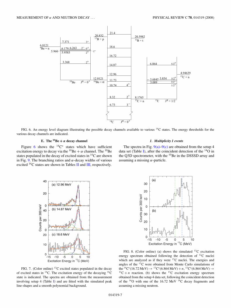
FIG. 6. An energy level diagram illustrating the possible decay channels available to various 14C states. The energy thresholds for thevarious decay channels are indicated.
E. The 10Be + α decay channel
Figure 6 shows the 14C∗ states which have sufficientexcitation energy to decay via the 10Be + α channel. The 10Bestates populated in the decay of excited states in 14C are shownin Fig. 9. The branching ratios and α-decay widths of variousexcited 14C states are shown in Tables II and III, respectively.
-15 -10 -5 0 5 10Excitation Energy in
13C (MeV)
0
10
20
0
20
40
Cou
nts
per
300
keV 0
20
40(a) 12.96 MeV
(b) 14.87 MeV
(c) 18.6 MeV
FIG. 7. (Color online) 13C excited states populated in the decayof excited states in 14C. The excitation energy of the decaying 14Cstate is indicated. The spectra are obtained from the measurementinvolving setup 4 (Table I) and are fitted with the simulated peakline-shapes and a smooth polynomial background.
1. Multiplicity 1 events
The spectra in Fig. 9(a)–9(c) are obtained from the setup 4data set (Table I), after the coincident detection of the 14O inthe Q3D spectrometer, with the 10Be in the DSSSD array andassuming a missing α-particle.
-15 -10 -5 0 5 10Excitation Energy in
13C (MeV)
0
10
20
30
Cou
nts
per
300
keV
0
10
20
30(a)
(b)
FIG. 8. (Color online) (a) shows the simulated 13C excitationenergy spectrum obtained following the detection of 12C nucleiwhich are analyzed as if they were 13C nuclei. The energies andangles of the 12C were obtained from Monte Carlo simulations ofthe 14C∗(16.72 MeV) → 13C∗(6.864 MeV) + n, 13C∗(6.864 MeV) →12C + n reaction. (b) shows the 13C excitation energy spectrumobtained from the setup 4 data set, following the coincident detectionof the 14O with one of the 16.72 MeV 14C decay fragments andassuming a missing neutron.
014319-7
P. J. HAIGH et al. PHYSICAL REVIEW C 78, 014319 (2008)
-10 -5 0 5 10
Excitation Energy in 10
Be (MeV)
0
20
40
0
20
40
Cou
nts
per
300
keV
0
50
100 (a) 14.87 MeV
(b) 18.6 MeV
(c) 21.4 MeV
-10 -5 0 5 10
Excitation Energy in 10
Be (MeV)
0
2
4
6
0
2
4
6
Cou
nts
per
500
keV 0
2
4
6(d) 14.87 MeV
(e) 18.6 MeV
(f) 21.4 MeV
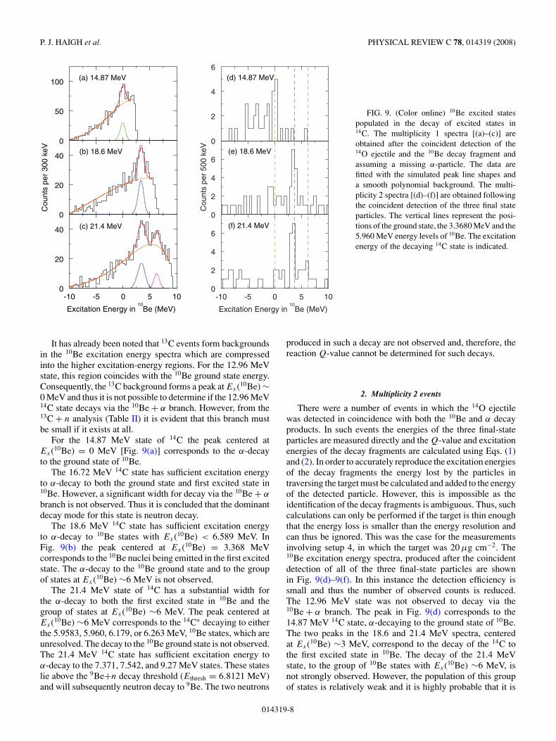
FIG. 9. (Color online) 10Be excited statespopulated in the decay of excited states in14C. The multiplicity 1 spectra [(a)–(c)] areobtained after the coincident detection of the14O ejectile and the 10Be decay fragment andassuming a missing α-particle. The data arefitted with the simulated peak line shapes anda smooth polynomial background. The multi-plicity 2 spectra [(d)–(f)] are obtained followingthe coincident detection of the three final stateparticles. The vertical lines represent the posi-tions of the ground state, the 3.3680 MeV and the5.960 MeV energy levels of 10Be. The excitationenergy of the decaying 14C state is indicated.
It has already been noted that 13C events form backgroundsin the 10Be excitation energy spectra which are compressedinto the higher excitation-energy regions. For the 12.96 MeVstate, this region coincides with the 10Be ground state energy.Consequently, the 13C background forms a peak at Ex(10Be) ∼0 MeV and thus it is not possible to determine if the 12.96 MeV14C state decays via the 10Be + α branch. However, from the13C + n analysis (Table II) it is evident that this branch mustbe small if it exists at all.
For the 14.87 MeV state of 14C the peak centered atEx(10Be) = 0 MeV [Fig. 9(a)] corresponds to the α-decayto the ground state of 10Be.
The 16.72 MeV 14C state has sufficient excitation energyto α-decay to both the ground state and first excited state in10Be. However, a significant width for decay via the 10Be + α
branch is not observed. Thus it is concluded that the dominantdecay mode for this state is neutron decay.
The 18.6 MeV 14C state has sufficient excitation energyto α-decay to 10Be states with Ex(10Be) < 6.589 MeV. InFig. 9(b) the peak centered at Ex(10Be) = 3.368 MeVcorresponds to the 10Be nuclei being emitted in the first excitedstate. The α-decay to the 10Be ground state and to the groupof states at Ex(10Be) ∼6 MeV is not observed.
The 21.4 MeV state of 14C has a substantial width forthe α-decay to both the first excited state in 10Be and thegroup of states at Ex(10Be) ∼6 MeV. The peak centered atEx(10Be) ∼6 MeV corresponds to the 14C∗ decaying to eitherthe 5.9583, 5.960, 6.179, or 6.263 MeV, 10Be states, which areunresolved. The decay to the 10Be ground state is not observed.The 21.4 MeV 14C state has sufficient excitation energy toα-decay to the 7.371, 7.542, and 9.27 MeV states. These stateslie above the 9Be+n decay threshold (Ethresh = 6.8121 MeV)and will subsequently neutron decay to 9Be. The two neutrons
produced in such a decay are not observed and, therefore, thereaction Q-value cannot be determined for such decays.
2. Multiplicity 2 events
There were a number of events in which the 14O ejectilewas detected in coincidence with both the 10Be and α decayproducts. In such events the energies of the three final-stateparticles are measured directly and the Q-value and excitationenergies of the decay fragments are calculated using Eqs. (1)and (2). In order to accurately reproduce the excitation energiesof the decay fragments the energy lost by the particles intraversing the target must be calculated and added to the energyof the detected particle. However, this is impossible as theidentification of the decay fragments is ambiguous. Thus, suchcalculations can only be performed if the target is thin enoughthat the energy loss is smaller than the energy resolution andcan thus be ignored. This was the case for the measurementsinvolving setup 4, in which the target was 20 µg cm−2. The10Be excitation energy spectra, produced after the coincidentdetection of all of the three final-state particles are shownin Fig. 9(d)–9(f). In this instance the detection efficiency issmall and thus the number of observed counts is reduced.The 12.96 MeV state was not observed to decay via the10Be + α branch. The peak in Fig. 9(d) corresponds to the14.87 MeV 14C state, α-decaying to the ground state of 10Be.The two peaks in the 18.6 and 21.4 MeV spectra, centeredat Ex(10Be) ∼3 MeV, correspond to the decay of the 14C tothe first excited state in 10Be. The decay of the 21.4 MeVstate, to the group of 10Be states with Ex(10Be) ∼6 MeV, isnot strongly observed. However, the population of this groupof states is relatively weak and it is highly probable that it is
014319-8

MEASUREMENT OF α AND NEUTRON DECAY . . . PHYSICAL REVIEW C 78, 014319 (2008)
TABLE IV. The theoretical decay branch ratios for the neutron decay of various 14C∗ states to the 13C ground state (1/2−) as a fraction ofthe neutron decay to any of the first three excited states (1/2+, 3/2−, 5/2+). The ratios are shown for Ji = 0 to 8 for both the even and oddparity states. The numbers in the brackets represent the strength of the 1/2+, 3/2− and 5/2+ decay widths as a fraction of their total width.Also shown are the associated experimental relative branching ratios. A comparison between the experimental and theoretical ratios providesinformation on the spin, parity and structure of the decaying 14C state.
J πi Ex (MeV)
11.73 12.96 14.87 16.72 18.6
0− 5.12 (1, 0, 0) 1.55 (0.75, 0.23, 0.02) 0.78 (0.51, 0.34, 0.15) 0.59 (0.44, 0.34, 0.22) 0.51 (0.40, 0.34, 0.26)1− 8.66 (1, 0, 0) 1.23 (0.34, 0.44, 0.23) 0.72 (0.26, 0.44, 0.30) 0.59 (0.24, 0.42, 0.34) 0.54 (0.23, 0.42, 0.36)2− 3.51 (1, 0, 0) 0.50 (0.37, 0.42, 0.21) 0.29 (0.33, 0.40, 0.27) 0.23 (0.31, 0.40, 0.29) 0.20 (0.30, 0.40, 0.30)3− 404.42 (1, 0, 0) 1.82 (0.14, 0.27, 0.59) 0.79 (0.19, 0.31, 0.50) 0.59 (0.20, 0.33, 0.48) 0.51 (0.19, 0.34, 0.47)4− 64.22 (1, 0, 0) 0.99 (0.32, 0.62, 0.06) 0.39 (0.31, 0.49, 0.20) 0.30 (0.31, 0.45, 0.24) 0.25 (0.31, 0.43, 0.27)5− 14.25 (0.03, 0.10, 0.87) 1.56 (0.06, 0.21, 0.73) 0.88 (0.11, 0.28, 0.61) 0.66 (0.15, 0.31, 0.55)6− 3.79 (0.25, 0.74, 0.01) 0.47 (0.21, 0.72, 0.07) 0.30 (0.24, 0.62, 0.14) 0.26 (0.27, 0.54, 0.19)7− 302.46 (0.02, 0.05, 0.93) 5.88 (0.02, 0.09, 0.90) 1.84 (0.03, 0.14, 0.84) 1.07 (0.04, 0.19, 0.76)8− 21.92 (0.28, 0.72, 0.00) 0.71 (0.14, 0.83, 0.03) 0.27 (0.15, 0.79, 0.06) 0.19 (0.17, 0.74, 0.09)0+ 2.49(1, 0, 0) 0.87 (0.56, 0.33, 0.11) 0.54 (0.42, 0.34, 0.24) 0.46 (0.39, 0.34, 0.27) 0.43 (0.37, 0.34, 0.29)1+ 25.10(1, 0, 0) 1.21 (0.36, 0.49, 0.15) 0.53 (0.29, 0.46, 0.26) 0.39 (0.26, 0.44, 0.30) 0.33 (0.24, 0.43, 0.33)2+ 36.10(1, 0, 0) 1.20 (0.23, 0.31, 0.46) 0.65 (0.21, 0.33, 0.46) 0.52 (0.20, 0.34, 0.46) 0.46 (0.19, 0.34, 0.47)3+ 10.98(1, 0, 0) 0.43 (0.23, 0.31, 0.46) 0.25 (0.24, 0.32, 0.44) 0.20 (0.25, 0.33, 0.42) 0.18 (0.25, 0.33, 0.42)4+ 7922.09(1, 0, 0) 3.93 (0.06, 0.17, 0.77) 1.03 (0.13, 0.29, 0.59) 0.70 (0.17, 0.31, 0.52) 0.57 (0.18, 0.32, 0.49)5+ 415.67(1, 0, 0) 0.42 (0.06, 0.17, 0.77) 0.21 (0.13, 0.29, 0.58) 0.19 (0.18, 0.31, 0.52) 0.18 (0.20, 0.32, 0.48)6+ 66.55 (0.02, 0.07, 0.91) 2.89 (0.03, 0.13, 0.84) 1.22 (0.05, 0.21, 0.74) 0.82 (0.09, 0.26, 0.65)7+ 0.82 (0.02, 0.07, 0.91) 0.09 (0.03, 0.13, 0.84) 0.08 (0.05, 0.21, 0.74) 0.09 (0.09, 0.26, 0.65)8+ 1319.19 (0.02, 0.05, 0.93) 11.90 (0.01, 0.07, 0.92) 2.87 (0.01, 0.10, 0.89) 1.44 (0.02, 0.13, 0.84)Expt. 2.57±0.39 0.57±0.13 0.37±0.09 <0.37
not observed due to the low statistics and the small detectionefficiency. Thus, the multiplicity 1 and 2 data are found to beconsistent.
F. Decay widths
The theoretical decay branches of the various decaychannels were calculated using R-matrix penetrabilities [22].For neutron decay from an initial 14C state feeding a 13C state,the decay width is given by
�13C[Jf ] =∑
jnn
�Ji
Jf jnn. (6)
Here �Ji
Jf jnn= 2γ 2P, where P is the JWKB penetration
factor of Ref. [22] and γ 2 is the reduced width. For thepurpose of comparison γ 2 has been assumed to be 1. Ji
is the total angular momentum of the parent nucleus andJf is the angular momentum of the daughter nucleus. Thepermissible angular momentum combinations (jnn) for theoutgoing neutron are subject to the condition �Ji = �Jf + �jn
and n is either even or odd depending on the transition.The decay branches were calculated for each allowed neutrondecay channel of the excited 14C states of interest. The ratiosof the decay branches associated with two different decaychannels were then calculated over a range of Jπ
i values.The decay branch ratio for the neutron decay of the 14C∗ to
the 13C ground state (1/2−) as a fraction of the neutron decayto any of the first three excited states (1/2+, 3/2−, 5/2+), is
given by
R =�13C[ 1
2−
]
�13C[ 12
+] + �13C[ 3
2−
] + �13C[ 52
+]
. (7)
Here the decay branches of the first three excited states aresummed together as they were experimentally unresolved. Theratios were calculated for Ji = 0 to 8 for both the even and oddparity states and are shown in Table IV. Also shown are theassociated experimental relative branching ratios calculatedfrom the absolute branching ratios of Table II.
The theoretical and the experimentally determined ratioswere then compared to provide information on the spin, parityand possible single particle structure of the decaying 14C state.Differences between the ratios also provides information onthe relative reduced widths as γ 2 has been assumed to be 1.
For the α-decay from an initial 14C∗ state feeding a 10Befinal state, the decay branches were calculated for each allowedα-decay channel and various ratios of the decay branches werecalculated. The ratio of the α-decay branch to the 10Be groundstate (0+) as a fraction of the α-decay branch to the first excitedstate (2+), is given by
R = �10Be[0+]
�10Be[2+]. (8)
Table V shows these ratios for Jπ = 0 to 8 for natural paritystates. Note that the α-decay of an unnatural parity state to the10Be ground state is forbidden.
Table VI shows the ratios of the neutron decay branch tothe 13C ground state as a fraction of the α-decay branch to the
014319-9
P. J. HAIGH et al. PHYSICAL REVIEW C 78, 014319 (2008)
TABLE V. Theoretical ratios of the α-decay branchto the 10Be[0+] ground state as a fraction of the α-decaybranch to the first excited state (2+). Also shown arethe associated experimental relative branching ratios.
J πi Ex (MeV)
18.6 21.4
0+ 3.56 1.741− 1.68 0.882+ 0.96 0.573− 1.07 0.634+ 1.14 0.685− 1.15 0.686+ 1.21 0.587− 1.39 0.478+ 1.71 0.41Expt. <0.33 <0.15
10Be ground state (�13C[1/2−]/�10Be[0+]) and the ratios of thedecay branch to the 13C ground state compared to the decaybranch to the first excited state in 10Be (�13C[1/2−]/�10Be[2+]).These ratios provide information on the α-cluster content of astate.
IV. DISCUSSION OF THE EXCITED 14C STATES
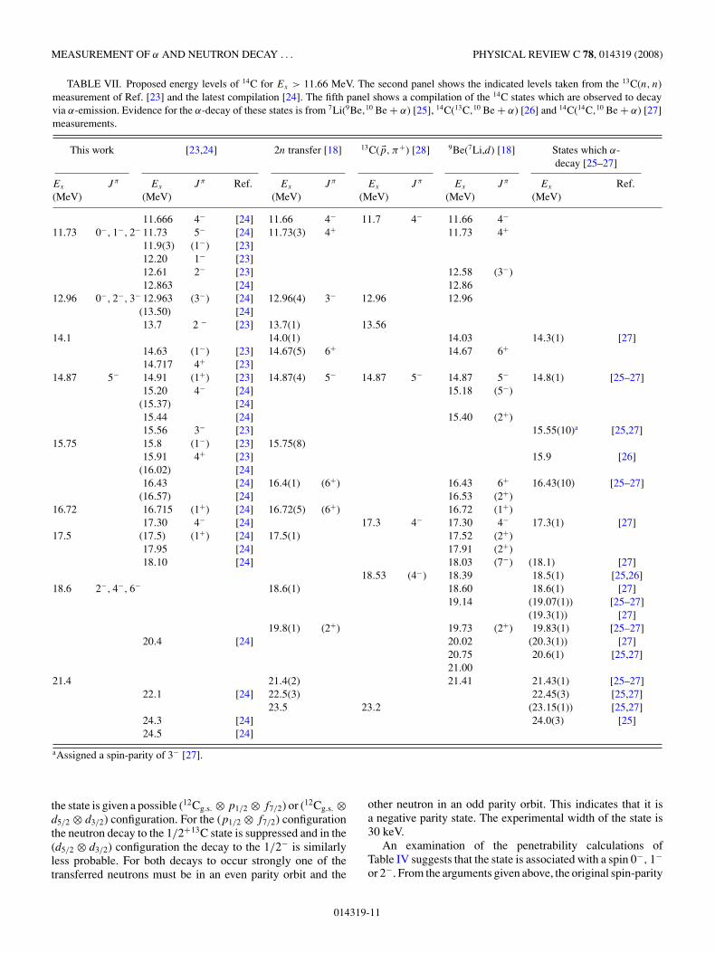
The present spectrum of the excited states of 14C withEx >11.66 MeV is summarized in Table VII. The fifth panelshows the 14C states which have been observed to decay viaα-emission.
The 14C states which are strongly populated in the two-neutron stripping reaction depend sensitively on dynamicalmatching conditions [29] and have been dominantly connectedto stretched two-neutron configurations [30]. Such configu-rations are built by coupling the 12C ground state with thetwo stripped neutrons which can occupy a combination of
various orbits. The population strength of these orbits havebeen examined by Bohlen et al. [30]. The population of thes1/2 orbital is very weak, the population of states containingp1/2 and d3/2 components are expected to be medium andthe d5/2 is expected to be strong. At higher 14C excitationenergies there will also be combinations with the f7/2 whichis also expected to be strongly populated. As an example,the 6.73 and 10.74 MeV states have (12Cg.s. ⊗ p1/2 ⊗ d5/2)and (12Cg.s. ⊗ d5/2 ⊗ d5/2) configurations, respectively. Thus,one would expect these two states to be strongly populatedin the two-neutron stripping reaction, as confirmed by anexamination of Fig. 1.
Some of the 14C∗ states at higher excitation energies whichare less strongly populated can be related to core excitations(12C∗
2+ and 12C∗3− ). For a 2+ core excitation, the states would
be populated in a multistep process, the first step being thecollective excitation of the system followed by the transferof the two neutrons into the final orbits [31]. Again thematching conditions favor the population of stretched con-figurations of the two neutrons in the final state and high-spinstates.
Below, is a list of some of the individual 14C∗ statespopulated in the two-neutron transfer reaction. The populationand decay characteristics of the states, along with the pen-etrability ratio calculations, are used to extract informationon their spins, parities and configurations. A summary ofthe results can be found in Table VIII. The third columnshows the predicted excitation energies of the 12C core plustwo-neutron configurations which have been calculated by vonOertzen et al. [18] using the simple shell-model approach ofChan [32,33].
A. 11.73 MeV
The 11.73 MeV state is observed to neutron decay to boththe 13C 1/2− ground state and the 1/2+ first excited state witha ratio of 2.57 ± 0.39. From Fig. 6 it is evident that these are theonly two decay channels available for this state. In Ref. [18]
TABLE VI. Theoretical ratios of the neutron decay branch to the 13C ground state as a fraction of the α-decaybranch to the 10Be ground state (�13C[1/2−]/�10Be[0+]) and the ratio of the decay to the 13C ground state compared tothe decay to the first excited state in 10Be (�13C[1/2−]/�10Be[2+]). Also shown are the associated experimental relativebranching ratios.
Ex (MeV) 12.96 14.87 16.72 18.6 21.4 16.72 18.6 21.4J π
i �13C[ 12
−]
�10Be[0+]
�13C[ 12
−]
�10Be[2+ ]
0+ 35.79 2.25 1.54 1.32 1.18 89.57 4.69 2.051− 162.35 5.43 3.33 2.76 2.41 43.81 4.64 2.122+ 716.31 8.10 3.84 2.94 2.48 18.88 2.83 1.423− 17.83 5.22 3.37 2.61 32.29 3.62 1.654+ 61.32 9.47 4.47 2.90 91.93 5.09 1.975− 295.36 24.95 7.68 3.59 431.68 8.84 2.426+ 86.30 18.13 5.50 21.99 3.207− 299.12 50.86 10.89 70.57 5.138+ 863.09 132.42 24.20 225.92 9.81Expt. <3.4 1.31±0.35 <0.64 <0.08
014319-10
MEASUREMENT OF α AND NEUTRON DECAY . . . PHYSICAL REVIEW C 78, 014319 (2008)
TABLE VII. Proposed energy levels of 14C for Ex > 11.66 MeV. The second panel shows the indicated levels taken from the 13C(n, n)measurement of Ref. [23] and the latest compilation [24]. The fifth panel shows a compilation of the 14C states which are observed to decayvia α-emission. Evidence for the α-decay of these states is from 7Li(9Be,10 Be + α) [25], 14C(13C,10 Be + α) [26] and 14C(14C,10 Be + α) [27]measurements.
This work [23,24] 2n transfer [18] 13C( �p, π+) [28] 9Be(7Li,d) [18] States which α-decay [25–27]
Ex
(MeV)J π Ex
(MeV)J π Ref. Ex
(MeV)J π Ex
(MeV)J π Ex
(MeV)J π Ex
(MeV)Ref.
11.666 4− [24] 11.66 4− 11.7 4− 11.66 4−
11.73 0−, 1−, 2− 11.73 5− [24] 11.73(3) 4+ 11.73 4+
11.9(3) (1−) [23]12.20 1− [23]12.61 2− [23] 12.58 (3−)12.863 [24] 12.86
12.96 0−, 2−, 3− 12.963 (3−) [24] 12.96(4) 3− 12.96 12.96(13.50) [24]13.7 2 − [23] 13.7(1) 13.56
14.1 14.0(1) 14.03 14.3(1) [27]14.63 (1−) [23] 14.67(5) 6+ 14.67 6+
14.717 4+ [23]14.87 5− 14.91 (1+) [23] 14.87(4) 5− 14.87 5− 14.87 5− 14.8(1) [25–27]
15.20 4− [24] 15.18 (5−)(15.37) [24]15.44 [24] 15.40 (2+)15.56 3− [23] 15.55(10)a [25,27]
15.75 15.8 (1−) [23] 15.75(8)15.91 4+ [23] 15.9 [26]
(16.02) [24]16.43 [24] 16.4(1) (6+) 16.43 6+ 16.43(10) [25–27]
(16.57) [24] 16.53 (2+)16.72 16.715 (1+) [24] 16.72(5) (6+) 16.72 (1+)
17.30 4− [24] 17.3 4− 17.30 4− 17.3(1) [27]17.5 (17.5) (1+) [24] 17.5(1) 17.52 (2+)
17.95 [24] 17.91 (2+)18.10 [24] 18.03 (7−) (18.1) [27]
18.53 (4−) 18.39 18.5(1) [25,26]18.6 2−, 4−, 6− 18.6(1) 18.60 18.6(1) [27]
19.14 (19.07(1)) [25–27](19.3(1)) [27]
19.8(1) (2+) 19.73 (2+) 19.83(1) [25–27]20.4 [24] 20.02 (20.3(1)) [27]
20.75 20.6(1) [25,27]21.00
21.4 21.4(2) 21.41 21.43(1) [25–27]22.1 [24] 22.5(3) 22.45(3) [25,27]
23.5 23.2 (23.15(1)) [25,27]24.3 [24] 24.0(3) [25]24.5 [24]
aAssigned a spin-parity of 3− [27].
the state is given a possible (12Cg.s. ⊗ p1/2 ⊗ f7/2) or (12Cg.s. ⊗d5/2 ⊗ d3/2) configuration. For the (p1/2 ⊗ f7/2) configurationthe neutron decay to the 1/2+13C state is suppressed and in the(d5/2 ⊗ d3/2) configuration the decay to the 1/2− is similarlyless probable. For both decays to occur strongly one of thetransferred neutrons must be in an even parity orbit and the
other neutron in an odd parity orbit. This indicates that it isa negative parity state. The experimental width of the state is30 keV.
An examination of the penetrability calculations ofTable IV suggests that the state is associated with a spin 0−, 1−or 2−. From the arguments given above, the original spin-parity
014319-11
P. J. HAIGH et al. PHYSICAL REVIEW C 78, 014319 (2008)
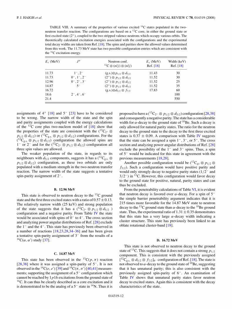
TABLE VIII. A summary of the properties of various excited 14C states populated in the two-neutron transfer reaction. The configurations are based on a 12C core, in either the ground state orfirst excited state (2+), coupled to the two stripped valence neutrons which occupy various orbits. Thetheoretically calculated excitation energies associated with the configurations and the experimentaltotal decay widths are taken from Ref. [18]. The spins and parities show the allowed values determinedfrom this work. The 11.73 MeV state has two possible configuration entries which are consistent withthe 14C excitation energy.
Ex (MeV) J π Neutron conf. Ex (MeV) Width (keV)12C ⊗ (nlj ) ⊗ (nlj ) Ref. [18] Ref. [18]
11.73 1−, 2− (g.s.)⊗p1/2 ⊗ d3/2 11.43 3011.73 0−, 1−, 2− (2+) ⊗ p1/2 ⊗ d5/2 11.52 3012.96 0−, 2−, 3− (2+) ⊗ p1/2 ⊗ d5/2 11.52 2514.87 5− (2+) ⊗ p1/2 ⊗ d5/2 11.52 3516.72 (g.s.)⊗d5/2 ⊗ f7/2 17.83 6018.6 2−, 4−, 6− 10021.4 550
assignments of 4+ [18] and 5− [23] have to be consideredto be wrong. The narrow width of the state and the spinand parity assignments coupled with the energy calculationsof the 12C core plus two-nucleon model of [18] show thatthe properties of the state are consistent with the (12C2+ ⊗p1/2 ⊗ d5/2) or (12Cg.s. ⊗ p1/2 ⊗ d3/2) configurations. For the(12Cg.s. ⊗ p1/2 ⊗ d3/2) configuration the allowed spins are1− or 2− and for the (12C2+ ⊗ p1/2 ⊗ d5/2) configuration allthree spin values are allowed.
The weaker population of the state, in regards to itsneighbours with d5/2 components, suggests it has a (12Cg.s. ⊗p1/2 ⊗ d3/2) configuration, as these two orbitals are onlypopulated with a medium strength in the two-neutron transferreaction. The narrow width of the state suggests a tentativespin-parity assignment of 2−.
B. 12.96 MeV
This state is observed to neutron decay to the 13C groundstate and the first three excited states with a ratio of 0.57 ± 0.13.The relatively narrow width (25 keV) and strong populationof the state suggests that it has a (12C2+ ⊗ p1/2 ⊗ d5/2 )configuration and a negative parity. From Table IV the statewould be associated with spins of 0− to 4−. The cross sectionand analyzing power angular distributions of Ref. [28] excludethe 1− and the 4−. This state has previously been observed ina number of reactions [18,23,28,34–36] and has been givena tentative spin-parity assignment of 3− from the results of a14C(α, α′) study [37].
C. 14.87 MeV
This state has been observed in the 13C(p, π ) reaction[28,38] where it was assigned a spin-parity of 5−. It is notobserved in the 14C(e, e′) [39] and 14C(π, π ′) [40,41] measure-ments; supporting the assignment of a 5− configuration whichcannot be reached by 1p1h excitations from the ground state of14C. It can thus be clearly described as a core excitation and itis demonstrated to be the analog of a 5− state in 14N. Thus it is
proposed to have a (12C2+ ⊗ p1/2 ⊗ d5/2) configuration [28,38]and consequently a negative parity. The state has a considerablewidth for α-decay to the ground state of 10Be. Such a decay isonly allowed for natural parity states. The ratio for the neutrondecay to the ground state to the decay to the first three excitedstates is 0.37 ± 0.09. A comparison with Table IV suggeststhat the state can be assigned a spin 1−, 3−, or 5−. The crosssection and analyzing power angular distributions of Ref. [28]exclude the possibility of the 1− and 3− spins. Thus, a spinof 5− would be indicated for this state in agreement with theprevious measurements [18,28].
Another possible configuration would be (12Cgs ⊗ p1/2 ⊗f3/2). Such a configuration would have positive parity andwould only strongly decay to negative parity states (1/2− and3/2−) in 13C. However, this configuration would favor decayto the ground state for positive, natural, parity states and canthus be excluded.
From the penetrability calculations of Table VI, it is evidentthat neutron decay is favored over α-decay. For a spin of 5−the simple barrier penetrability argument indicates that it is215 times more favorable for the 14.87 MeV state to neutrondecay to the 13C ground state than α-decay to the 10Be groundstate. Thus, the experimental ratio of 1.31 ± 0.35 demonstratesthat this state has a very large α-decay width indicating acluster structure. This state has previously been linked to anoblate rotational cluster-band [18].
D. 16.72 MeV
This state is not observed to neutron decay to the groundstate of 13C. This suggests that it does not contain a strong p1/2
component. This is consistent with the previously assigned[12Cg.s. ⊗ d5/2 ⊗ f7/2]6− configuration of Ref. [18]. The state isnot observed to α-decay to the ground state of 10Be, suggestingthat it has unnatural parity; this is also consistent with thepreviously assigned spin-parity of 6−. An examination ofTable IV shows that unnatural parity states favor neutrondecay to excited states. Again this is consistent with the decaycharacteristics of the state.
014319-12
MEASUREMENT OF α AND NEUTRON DECAY . . . PHYSICAL REVIEW C 78, 014319 (2008)
E. 18.6 MeV
The neutron decay of this state proceeds mostly to the firstthree excited states in 13C. The state has a substantial width forα-decay to the first excited state in 10Be[2+]. The decay to the10Be[0+] ground state is very weak if present at all. This is incontrast with Soic et al. [25] in which a broad state at 18.5 MeVwas observed to have a substantial width for α-decay to boththe 10Be[2+] and 10Be[0+]. This broad structure has previouslybeen associated with both the 18.39 and 18.6 MeV states intwo-neutron transfer reactions [18]. It must now be assumedthat the state in Ref. [25] is the 18.39 MeV state which hasbeen observed in various other measurements [18,26,28,41]and the present structure is the 18.6 MeV state. This structuremay still involve several states, however, if it is a single stateits broad width suggests that it has a low spin. The fact that itdoes not decay to the 10Be[0+] indicates that it has unnaturalparity.
An examination of Table IV suggests that the state isassociated with spins 2−, 4−, or 6−. It is also evident that anunnatural parity state strongly favors neutron decay to excitedstates, as was experimentally observed. This state is populatedin the 13C(p, π+) [28,38] and 14C(π, π ′) [40,41] reactions,indicating a core excitation. It has previously been given atentative spin-parity assignment of 6− [18].
From Table VI it is evident that neutron decay to theground state is favored over α-decay to the 2+ in terms ofthe penetrability factors. Thus, the fact that α-decay is favoredindicates that this state has a large α-decay width and is apossible cluster-structure candidate.
F. 21.4 MeV
This state has previously been observed as a broad structurein a number of reactions [18,25,26,28,41,42]. The large width(550 keV) suggests that it has a component with low spin.However, it may involve several states. It is seen to α-decay toboth the 2+ and the group of states at ∼6 MeV but the decay to
the 0+ ground state is not observed. This is consistent witha previous decay study using the 7Li(9Be,14C → 10Be+α)reaction [25]. The state is not observed to neutron decay. Thelarge α-decay width suggests that it is a possible cluster state.
V. CONCLUSIONS
The decay modes and associated branching ratios of variousexcited 14C states populated in the 12C(16O,14O)14C reactionhave been studied. The strong dependence of the transfer crosssection on dynamical matching conditions for different finalconfigurations has been used to make tentative configurationassignments for many of the observed states. Theoretical decaybranch ratios have been calculated from barrier penetrationfactors and have been used to provide information on the spins,parities, and single-particle configurations of the states.
The 14.87, 18.6, and 21.4 MeV states have been shown topossess large α-decay widths and are possible cluster structurecandidates. The 16.72 MeV state has no α-decay width andappears to have a single-particle structure. The 11.73 and12.96 MeV states lie close to the 10Be+α decay thresholdand are thus not seen to α-decay. Thus, it is hard to determinethe nature of their structure.
The present measurements of the partial widths may becombined with subsequent measurements of spins to providedefinitive evidence for the cluster nature of the states. Suchmeasurements are planned for the near future.
ACKNOWLEDGMENTS
The authors would like to thank the staff members ofthe Hahn-Meitner-Institut for their assistance in running theexperiments. We acknowledge the financial support of theU.K. Engineering and Physical Sciences Research Council(EPSRC).
[1] B. Buck, H. Friedrich, and C. Wheatley, Nucl. Phys. A275, 246(1977).
[2] J. Hiura and R. Tamagaki, Suppl. Prog. Theor. Phys. 52, 25(1972).
[3] Y. Kanada-En’yo, H. Horiuchi, and A. Dote, Phys. Rev. C 60,064304 (1999).
[4] W. von Oertzen, Z. Phys. A 354, 37 (1996).[5] W. von Oertzen, Z. Phys. A 357, 355 (1997).[6] W. von Oertzen, Nuovo Cimento 110A, 895 (1997).[7] M. Freer, J. C. Angelique, L. Axelsson, B. Benoit, U. Bergmann,
W. N. Catford, S. P. G. Chappell, N. M. Clarke, N. Curtis,A. D’Arrigo et al., Phys. Rev. Lett. 82, 1383 (1999).
[8] M. Freer, J. C. Angelique, L. Axelsson, B. Benoit, U. Bergmann,W. N. Catford, S. P. G. Chappell, N. M. Clarke, N. Curtis,A. D’Arrigo et al., Phys. Rev. C 63, 034301 (2001).
[9] M. Freer, J. C. Angelique, L. Axelsson, B. Benoit,U. Bergmann, W. N. Catford, S. P. G. Chappell, N. M. Clarke,N. Curtis, A. D’Arrigo et al., Phys. Rev. C 64, 019904(E)(2001).
[10] M. Freer, E. Casarejos, L. Achouri, C. Angulo, N. I. Ashwood,N. Curtis, P. Demaret, C. Harlin, B. Laurent, M. Milin, et al.,Phys. Rev. Lett. 96, 042501 (2006).
[11] Y. Kanada-En’yo, H. Horiuchi, and A. Ono, Phys. Rev. C 52,628 (1995).
[12] Y. Kanada-En’yo and H. Horiuchi, Phys. Rev. C 52, 647 (1995).[13] A. Dote, H. Horiuchi, and Y. Kanada-En’yo, Phys. Rev. C 56,
1844 (1997).[14] Y. Kanada-En’yo and H. Horiuchi, Phys. Rev. C 66, 024305
(2002).[15] Y. Kanada-En’yo, Phys. Rev. C 66, 011303(R) (2002).[16] Y. Kanada-En’yo and H. Horiuchi, Phys. Rev. C 68, 014319
(2003).[17] M. Milin and W. von Oertzen, Eur. Phys. J. A 14, 295 (2002).[18] W. von Oertzen, H. G. Bohlen, M. Milin, T. Kokalova,
S. Thummerer, A. Tumino, R. Kalpakchieva, T. N. Massey,Y. Eisermann, G. Graw et al., Eur. Phys. J. A 21, 193 (2004).
[19] A. G. Drentje, H. A. Enge, and S. B. Kowalski, Nucl. Instrum.Methods 122, 485 (1974).
014319-13
P. J. HAIGH et al. PHYSICAL REVIEW C 78, 014319 (2008)
[20] C. A. Wiedner, M. Goldschmidt, and D. Rieck, Nucl. Instrum.Methods 105, 205 (1972).
[21] M. Loffler, H. J. Scheerer, and H. Vonach, Nucl. Instrum.Methods 111, 1 (1973).
[22] A. M. Lane and R. G. Thomas, Rev. Mod. Phys. 30, 257 (1958).[23] D. A. Resler, H. D. Knox, P. E. Koehler, R. O. Lane, and G. F.
Auchampaugh, Phys. Rev. C 39, 766 (1989).[24] F. Ajzenberg-Selove, Nucl. Phys. A523, 1 (1991).[25] N. Soic, M. Freer, L. Donadille, N. M. Clarke, P. J. Leask, W. N.
Catford, K. L. Jones, D. Mahboub, B. R. Fulton, B. J. Greenhalghet al., Phys. Rev. C 68, 014321 (2003).
[26] D. Price, M. Freer, S. Ahmed, N. I. Ashwood, N. M. Clarke,N. Curtis, P. McEwan, C. J. Metelko, B. Novatski, S. Sakutaet al., Nucl. Phys. A765, 263 (2006).
[27] D. Price, M. Freer, N. I. Ashwood, N. M. Clarke, N. Curtis,L. Giot, V. Lima, P. McEwan, B. Novatski, N. A. Orr et al.,Phys. Rev. C 75, 014305 (2007).
[28] E. Korkmaz, S. E. Vigdor, W. W. Jacobs, T. G. Throwe, L. C.Bland, M. C. Green, P. L. Jolivette, and J. D. Brown, Phys. Rev.C 40, 813 (1989).
[29] D. M. Brink, Phys. Lett. B40, 37 (1972).[30] H. G. Bohlen, R. Kalpakchieva, B. Gebauer, S. M. Grimes,
H. Lenske, K. P. Lieb, T. N. Massey, M. Milin, W. von Oertzen,C. Schulz et al., Phys. Rev. C 68, 054606 (2003).
[31] W. von Oertzen and A. Vitturi, Rep. Prog. Phys. 64, 1247 (2001).[32] T. U. Chan, M. Agard, J. F. Bruandet, and C. Morand, Phys. Rev.
C 19, 244 (1979).[33] T. U. Chan, Phys. Rev. C 36, 838 (1987).[34] P. R. Andrews, B. M. Spicer, G. G. Shute, V. C. Officer, J. M.
R. Wastell, H. Nann, Q. Li, A. D. Bacher, D. L. Friesel, andW. P. Jones, Nucl. Phys. A468, 43 (1987).
[35] M. E. Clark and K. W. Kemper, Nucl. Phys. A425, 185 (1984).[36] R. O. Lane, H. D. Knox, P. Hoffmann-Pinther, R. M. White, and
G. F. Auchampaugh, Phys. Rev. C 23, 1883 (1981).[37] R. J. Peterson, H. C. Bhang, J. J. Hamill, and T. G. Masterson,
Nucl. Phys. A425, 469 (1984).[38] E. Korkmaz, L. C. Bland, W. W. Jacobs, T. G. Throwe, S. E.
Vigdor, M. C. Green, P. L. Jolivette, and J. D. Brown, Phys. Rev.Lett. 58, 104 (1987).
[39] R. A. Lindgren, J. Phys. (Paris), Colloq. C4, 433 (1984).[40] D. B. Holtkamp, S. J. Seestrom-Morris, S. Chakravarti,
D. Dehnhard, H. W. Baer, C. L. Morris, S. J. Greene, andC. J. Harvey, Phys. Rev. Lett. 47, 216 (1981).
[41] D. B. Holtkamp, S. J. Seestrom-Morris, D. Dehnhard, H. W.Baer, C. L. Morris, S. J. Greene, C. J. Harvey, D. Kurath, andJ. A. Carr, Phys. Rev. C 31, 957 (1985).
[42] J. D. Brown, L. K. Herold, K. E. Luther, A. A. Middleton, M. L.Pitt, D. Barker, and S. M. Aziz, Phys. Rev. C 38, 1958 (1988).
014319-14