mechanical design he
DESCRIPTION
heat exchanger design and calculation, ASME, TEMATRANSCRIPT

Program User Guide :
Doc. No. PUG - MDHE - 100Date 2005. 8. 15.Revision 0 1
1. Introduction Sheet No. 1 of 1
2. References
The program is based on the following, which shall be referred to for further understanding.Design TEMA, 8th Ed., 1999
ASME Sec. VIII, Div. 1Materials ASME Sec. II - D
TechnicalsProcess Vessel Design Manual, Dennis R. MossDesign of Process Equipment, 3rd Ed., K. K. MahajanCatalogues for Flanges
3. Future Development
Description Date Version RemarksPipe Shell 05. 8. 15. 0.1Nozzle 05. 8. 15. 0.1SaddleNozzle External LoadThermal Stress CalculationShell Expansion JointFloating Head
4. Program Architecture
Inside the ProgramInput and Summary SheetCalculation Sheet for ShellCalculation Sheet for ChannelCalculation Sheet for Shell …...Calculation Sheet for Channel …...Calculation Sheet for CoverCalculation Sheet for TubesheetCalculation Sheet for Shell FlangeCalculation Sheet for Channel Flange
Data Files
Material Index, Flange Data, Modulus of Elasticity, …...
5. General Information
NTES Narai Thermal Engineering Services
Mechanical Design of H / E in acc. with TEMA & ASME
This guide is intended to outline a program for mechnical design of heat exchangers in accordance withTEMA and ASME.
JIS B 8243 - 1981, 압력용기의 구조프로세스기기 구조설계 시리즈 6, " 열교환기 "
" IS "" shell "" channel "" s…... "" c…... "" cv "" ts "" s.flg "" c.flg "
" materials ASTM " Stress Values of ASTM / ASME materials" materials common "" materials JIS " Stress Values of JIS materials" materials KS " Stress Values of KS materials
Data are inputed via cells with blue words / numbers and comboboxes.Attention shall be paid to cells with red words / numbers.각 Sheet 의 하단에 나타나는 회사명을 바꾸려면 아래에 있는 푸른색 회사명을 바꾸기만 하면 된다.

PUG - MDHE - 1002005. 8. 15.
Narai Thermal Engineering Services
Design Notes :
Mechanical Design of H / E in acc. with TEMA & ASMEDoc. No. DN - MDHE - 100Date 2005. 3. 17.Revision 0
1. Introduction Sheet No. 1 of 1
These notes are intended to help designers follow normal design practices, and further reach an optimumdesign.
2. Notes
Flange
The procedures are from Taylor Forge Bulletin No. 502, 7th Ed., " Modern Flange Design ".
In general, bolts should be used in multiples of four(4).
For large diameter flanges, many smaller bolts on a tight bolt circle are recommended to reduce the flangethickness.
NTES Narai Thermal Engineering Services
Mechanical Design of H / E in acc. with TEMA & ASMEDN - MDHE - 100
2005. 3. 17.
Narai Thermal Engineering Services

Doc. No. MD - IS - 100
Date 2005. 8. 15.
Job No. S - 01 Item No. HE - 01 Revision 0
Project Sample Service Heat Exchanger Sheet No. 1 of 1
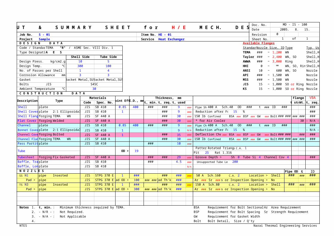
D E S I G N D A T A Available Flanges
Code / Standard TEMA "R" / ASME Sec. VIII Div. 1 Standard Nozzle Size, ID Type Typ. Use
Type Designation A E S TEMA 200 ~ 1,200 WN Shell,Head
Shell Side Tube Side Taylor 600 ~ 2,400 WN, SO Shell,Head
Design Press. kg/cm2.g 10 5 AWWA 100 ~ 3,000 Ring Shell,Head
Design Temp. ℃ 300 100 HHI 0 ~ ∞ WN, SO, Ring Shell,Head
No. of Passes per Shell 1 4 ANSI 10 ~ 600 WN, SO Nozzle
Corrosion Allowance mm 3 3 API 650 ~ 1,500 WN Nozzle
Gasket Jacket Metal,SUS Jacket Metal,SUS MSS 650 ~ 1,500 WN Nozzle
Bolts JIS S45C JIS 15 ~ 1,000 Nozzle
Ambient Temperature ℃ 30 KS 15 ~ 1,000 Nozzle
C O N S T R U C T I O N D A T A
Description TypeMaterials
Joint Eff. I.D., mmThickness, mm Flange VBA
Code Spec. No. t, min. t, req. t, used t std Wt. t, req.
Shell plate JIS SB 410 0.85 400 #VALUE! #VALUE! 9 ### Pipe Shell 400 A Sch.40 OD #VALUE! t ### ID #VALUE! #VALUE!
Shell Cover plate 2:1 Ellipsoidal JIS SB 410 1 #VALUE! 9 ### Reduction after Forming 15 % #VALUE!
Shell Flange forging TEMA WN JIS SF 440 A #VALUE! 30 ### 150 lb Confined BSA ### BSP ### GW ### Bolt ### ### ### ### #VALUE!
Flat Cover forging Welded JIS SF 440 A #VALUE! 30 ### * for Air Cooler 30 - N/A -
Channel plate JIS SB 410 0.85 400 #VALUE! #VALUE! 9 ### Pipe Chnl 400 A Sch.40 OD #VALUE! t ### ID #VALUE! #VALUE!
Bonnet Cover plate 2:1 Ellipsoidal JIS SB 410 1 9 - N/A - Reduction after Forming 15 % - N/A -
Channel Cover forging Bolted JIS SF 440 A 1 #VALUE! 35 ### Deflection Check ### BSA ### BSP ### GW ### Bolt ### ### ### #VALUE!
Channel Flange forging TEMA WN JIS SF 440 A #VALUE! 30 ### 150 lb Confined BSA ### BSP ### GW ### Bolt ### ### ### ### #VALUE!
Pass Partition plate JIS SB 410 #VALUE! 10 ###
Tube OD > 19 Pattern Rotated Triangular C.A. 0.5
Pitch 25 Ratio 1.316
Tubesheet forging FixedGasketed JIS SF 440 A #VALUE! #VALUE! 29 ### Groove Depth > Shell Side 0 Tube Side 4 Channel Cover 4 #VALUE!
Baffle, Trans. plate JIS SB 410 #VALUE! 4.5 ### Unsupported Tube Length 200
Baffle, Long. plate JIS SB 410 - N/A -
N O Z Z L E S Pipe OD t ID SS > N1 pipe Inserted JIS STPG 370 E 1 #VALUE! #VALUE! #VALUE! ### 50 A Sch.160 C.A. 1.5 Location > Shell ### ### ###
Pad > pipe JIS STPG 370 E Pad OD > 100 ### ### Pad Th'k> #VALUE! Ar ### Sr ### Access or Inspection Opening > No
TS > N3 pipe Inserted JIS STPG 370 E 1 #VALUE! #VALUE! #VALUE! ### 150 A Sch.80 C.A. 1.5 Location > Shell ### ### ###Pad > pipe JIS STPG 370 E Pad OD > 300 ### ### Pad Th'k> #VALUE! Ar ### Sr ### Access or Inspection Opening > No
Notes : 1. t, min. : Minimum thickness required by TEMA. BSA Requirement for Bolt Sectional Area Ar Area Requirement
2. - N/R - : Not Required. BSP Requirement for Bolt Spacing Sr Strength Requirement
3. - N/A - : Not Applicable GW Requirement for Gasket Width
4. Bolt Bolt Detail, Size / Q'ty
NTES Narai Thermal Engineering Services
I N P U T & S U M M A R Y S H E E T f o r H / E M E C H. D E S I G N
SO or Ring
SO or Ring

MD - IS - 100
2005. 8. 15.
Typ. Use
Shell,Head
Shell,Head
Shell,Head
Shell,Head
Nozzle
Nozzle
Nozzle
Nozzle
Nozzle
VBAt, req.
#VALUE!
#VALUE!
#VALUE!
- N/A -
#VALUE!
- N/A -
#VALUE!
#VALUE!
#VALUE!
ID###
###
Narai Thermal Engineering Services

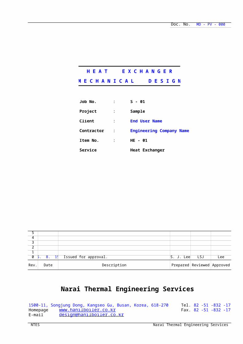
Doc. No. MD - PV - 000
H E A T E X C H A N G E R
M E C H A N I C A L D E S I G N
Job No. : S - 01
Project : Sample
Client : End User Name
Contractor : Engineering Company Name
Item No. : HE - 01
Service Heat Exchanger
543210 05. 8. 15. Issued for approval. S. J. Lee LSJ
Rev. Date Description Prepared Reviewed
Narai Thermal Engineering Services
1500-11, Songjung Dong, Kangseo Gu, Busan, Korea, 618-270 Tel. 82 -51 -832 -1715~8Homepage Fax. 82 -51 -832 -1719E-mail
NTES Narai Thermal Engineering Services

MD - PV - 000
Lee
Approved
Narai Thermal Engineering Services
82 -51 -832 -1715~8 82 -51 -832 -1719
Narai Thermal Engineering Services

H E A T E X C H A N G E R : Doc. No. MD - HE - 100
M E C H A N I C A L D E S I G N Date 05. 8. 15. Rev. 0 Sheet No. 1 of 1
T a b l e of C o n t e n t s
1. Design Data and Summary
2. Shell
3.
4.
5.
6.
7.
8.
9.
10.
NTES Narai Thermal Engineering Services
MD - HE - 10005. 8. 15.
Narai Thermal Engineering Services

H E A T E X C H A N G E R : Doc. No. MD - HE - 100
M E C H A N I C A L D E S I G NDate 05. 8. 15.
1 Revision 02 Sheet No. 1 of34 Project Sample5 Item No. HE - 016 Service Heat Exchanger78
D E S I G N D A T A910 Standard TEMA Class "R" Type A E S11 Code ASME Sec. VIII Div. 112 S H E L L S I D E T U B E S I D E13
Design Pressure 10 kg/cm2.g 5 kg/cm2.g
14 Temperature 300 ℃ 100 ℃15 No. of Passes per Shell 1 416
Corrosion Allowance
3 mm 3 mm17 Nozzle 1.5 mm 1.5 mm18 Tube 0.5 mm19 Joint Efficiency Shell / Cover 0.85 / 1 0.85 / 120 Radiography Shell / Cover Spot / No or Full Spot / No or Full21
Pressure Test Method
22 Pressure kg/cm2.g kg/cm2.g23
D E S I G N S U M M A R Y2425
Description Type MaterialID
Thickness
Remarks26 Min. Req. Used
27 mm28 Shell SB 410 400 ### ### 9
29 Shell Cover 2:1 Ellipsoidal SB 410 ### 9
30 Shell Flange TEMA / WN SF 440 A ### 30 150 lb
31 Flat Cover Welded SF 440 A ### 30
32 Channel SB 410 400 ### ### 9
33 Bonnet Cover34 Channel Cover Bolted SF 440 A ### 35
35 Channel Flange TEMA / WN SF 440 A ### 30 150 lb
36 Pass Partition SB 410 ### 10
37T U B E B U N D L E38
39
Description Type MaterialID OD
Thickness
Remarks40 Min. Req. Used
41 mm42 Tube 19
43 Tubesheet Gasketed SF 440 A ### ### 29
44 Baffle, Trans. SB 410 ### 4.5
45 Baffle, Long.46
N O Z Z L E S4748
Description Material LocationID OD
Thickness Pad
Remark49 Req. Used. Material OD t50 mm mm51 N1 STPG 370 E Shell ### ### ### ### #VALUE! ### ### ###
52 N3 STPG 370 E Shell ### ### ### ### #VALUE! ### ### ###
53545556 Remarks :57585960
NTES Narai Thermal Engineering Services
MD - HE - 10005. 8. 15.
x
D E S I G N D A T A
T U B E S I D E
D E S I G N S U M M A R Y
Remarks
T U B E B U N D L E
Remarks
N O Z Z L E S
Remark
Narai Thermal Engineering Services

H E A T E X C H A N G E R :
M E C H A N I C A L D E S I G N
Project Sample Doc. No. MD - HE - 100Item No. HE - 01 Sheet No. 0 of xService Heat Exchanger Revision 0
Part : Shell
Code : * Circumferential Stress in the Logitudinal Joint
t =P R
+ α =10.0 203
+ 3.0 = ### ### 9 mm used. #VALUE!S E - 0.6 P ### 0.85 - 0.6 10.0
Where, t minimum required thickness of shell mmP internal design pressure kg/cm2.gR inside radius of the shell course under consideration mmS maximum allowable stress value ###E joint efficiency for, or the efficiency of, appropriate joint in cylindical or spherical shellsα corrosion allowance mm
NTES Narai Thermal Engineering Services
ASME Sec. VIII Div. 1 UG-27 ( c ) ( 1 )

H E A T E X C H A N G E R :
M E C H A N I C A L D E S I G N
Project Sample Doc. No. MD - HE - 100Item No. HE - 01 Sheet No. 0 of xService Heat Exchanger Revision 0
Part : Shell Cover
Code : * 2:1 Ellipsoidal Head, t / L >= 0.002
t = (P R
+ α )100
= (10.0 203
+ 3.0 )100
S E - 0.1 P 100 - r ### 1 - 0.1 10.0 100 - 15
= ### ### 9 mm used. ###
Where, t minimum required thickness of shell mmP internal design pressure kg/cm2.gR inside radius of the shell course under consideration mmS maximum allowable stress value ###E lowest efficiency of any joint in the head; for hemi-spherical heads, this includes head-to-shell joint;
α corrosion allowance mmr thickness reduction rate after forming %
Code : * 10 % Dished Head ( Torispherical Head ), t / L >= 0.002
t = (0.885 P L
+ α )100
= (0.885 10.0 406
+ 3.0 )100
S E - 0.1 P 100 - r ### 1 - 0.1 10.0 100 - 15
= ### ### 9 mm used. ###
Where, L inside spherical or crown radius mm
NTES Narai Thermal Engineering Services
ASME Sec. VIII Div. 1 UG-32 ( d )
for welded vessels, use the efficiency specified in UW-12
ASME Sec. VIII Div. 1 UG-32 ( e )

1 Project Sample Doc. No. DF - WNFLG - 1002 Item No. HE - 01 Serivice Heat Exchanger Sheet No. 1 of 13 Description S H E L L F L A N G E * Design result ### Revision 0
1 D E S I G N C O N D I T I O N
4 Design Pressure kg/cm2.g 10 Allowable Stresses5 Design Temperature ℃ 300 Flange Bolting6 Atm. Temp. ℃ 30 Material JIS SF 440 A Material JIS S45C7 Corrosion Allowance mm 3 at Design Temp. ### #VALUE! at Design Temp. ### #VALUE!8 at Atm. Temp. ### #VALUE! at Atm. Temp. ### #VALUE!
2 G A S K E T & B O L T D E T A I L S 3 L O A D & B O L T C A L C U L A T I O N S
9 Gasket Material Jacket Metal,SUS kg #VALUE!cm2 #VALUE!10 Gasket Width, N cm #VALUE! kg #VALUE!
11 m #VALUE! kg #VALUE! cm2 #VALUE!12 y ### #VALUE! kg #VALUE! #VALUE!
13 / b cm ### ### kg #VALUE!14 G cm #VALUE!15 Bolt Size / Q'ty, n ### ### Required Gasket Width
cm ### ###16 cm ### ###17 Bolt Spacing cm ### ### <- * Min. / Max., TEMA ### / ###
4 M O M E N T C A L C U L A T I O N S
Load, kg x Lever Arm, cm = Moment, kg-cmOperating Condition
18 12,946 #VALUE! #VALUE!19 #VALUE! #VALUE! #VALUE!20 #VALUE! #VALUE! #VALUE!21 #VALUE!
Gasket Seating22 #VALUE! #VALUE! #VALUE!23
5 S H A P E F A C T O R S S K E T C H
24 K = A / B #VALUE! #VALUE!25 T #VALUE! F #VALUE!26 Z #VALUE! V #VALUE!27 Y #VALUE! f #VALUE! t = 30 h = ###28 U #VALUE! #VALUE! * STD ###29 #VALUE!
d =U
#VALUE!30 #VALUE! V31 E = ###
6 S T R E S S F O R M U L A F A C T O R S
#VA
LUE
!
W
#V
AL
UE
!
#VA
LUE
!
32 t 3.000 R = ###33 #VALUE!34 #VALUE!
*
#VA
LUE
!
35 #VALUE!###36 #VALUE!
37 #VALUE!
#V
AL
UE
!
#V
AL
UE
!
#V
AL
UE
!
38 #VALUE! ###39 #VALUE! tn = 940
A =
C =
G =
B = 406 41 multiplied by Bolt Spacing ID, uncorroded 400 42 : Nominal Bolt Dia. Unit : mm
7 #VALUE!
Allowable Stress Operating Condition Allowable Stress Gasket Seating
43 #VALUE!### Longitudinal Hub,
#VALUE! #VALUE!### Longitudinal Hub,
#VALUE!#VALUE! #VALUE!
44 #VALUE!### Radial Flange
#VALUE! #VALUE!### Radial Flange
#VALUE!#VALUE! #VALUE!
45 #VALUE!### Tangential Flange
#VALUE! #VALUE!### Tangential Flange
#VALUE!#VALUE! #VALUE!
46 #VALUE!###
#VALUE! #VALUE!###
#VALUE!#VALUE! #VALUE!
NTES Narai Thermal Engineering Services
W E L D I N G N E C K F L A N G E D E S I G N
Sfo Sb
Sfa Sa
Wm2 = b π G y Am = greater of Wm2/Sa
HP = 2 b π G m P or Wm1/Sb
H = G2 π P / 4 Ab = π / 4 d22
n Wm1 = HP + H Check Ab > Am
b0 W = 0.5 ( Am + Ab ) Sa
Bolt Dia. / Root Dia., d2 Nr = Ab Sa / 2 y π G < N
HD = π B2 P / 4 hD = R + 0.5 g1 MD = HD hD
HG = Wm1 - H hG = 0.5 ( C - G ) MG = HG hG
HT = H - HD hT = 0.5 ( R + g1 + hG ) MT = HT hT
Mo = MD + MG + MT
HG = W hG = 0.5 ( C - G ) Mo' = HG hG
h / h0
e = F / h0
g1 / g0h0 g0
2
h0 = Bg0
hG
α = t e + 1 hTHG
hD
β = 4/3 t e + 1 γ = α / T
HT HD g1= δ = t3 / d λ = γ + δ mo = Mo / B g0= mG = Mo' / B If bolt spacing exceeds 2 dB + t, mo and mG in above equations are
2 dB + t dB
1.5 Sfo 1.5 Sfa SH = f mo / λ g12 SH = f mG / λ g1
2
Sfo Sfa SR = β mo / λ t2 SR = β mG / λ t2
Sfo Sfa ST = mo Y / t2 - Z SR ST = mG Y / t2 - Z SR
Sfo
Greater of 0.5( SH + SR )Sfa
Greater of 0.5( SH + SR ) or 0.5( SH + ST ) or 0.5( SH + ST )

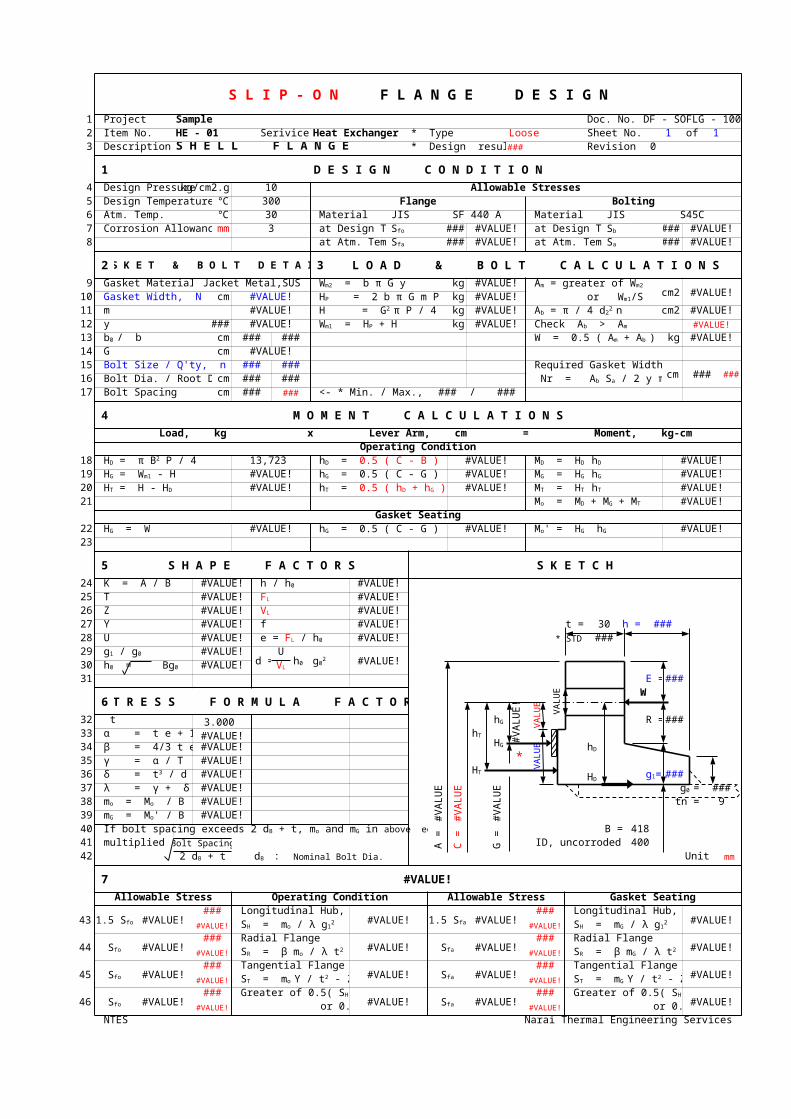
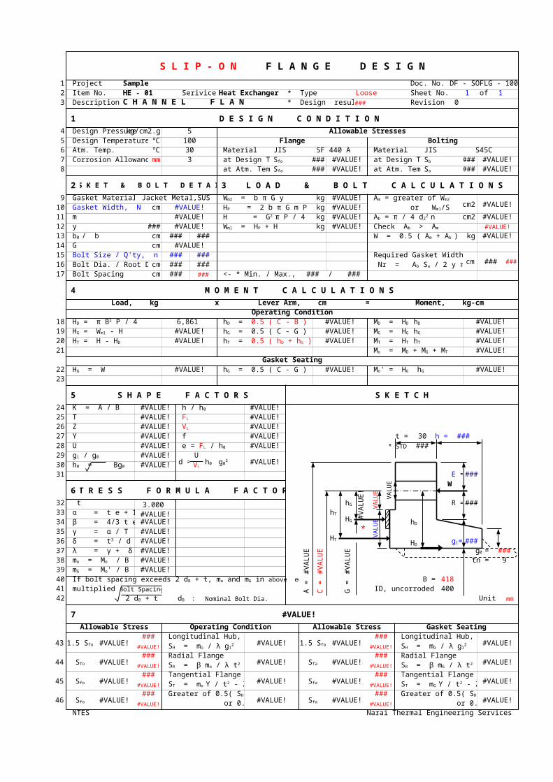
1 Project Sample Doc. No. DF - SOFLG - 1002 Item No. HE - 01 Serivice Heat Exchanger * Type Loose Sheet No. 1 of 13 Description S H E L L F L A N G E * Design result ### Revision 0
1 D E S I G N C O N D I T I O N
4 Design Pressure kg/cm2.g 10 Allowable Stresses5 Design Temperature ℃ 300 Flange Bolting6 Atm. Temp. ℃ 30 Material JIS SF 440 A Material JIS S45C7 Corrosion Allowance mm 3 at Design Temp. ### #VALUE! at Design Temp. ### #VALUE!8 at Atm. Temp. ### #VALUE! at Atm. Temp. ### #VALUE!
2 G A S K E T & B O L T D E T A I L S 3 L O A D & B O L T C A L C U L A T I O N S
9 Gasket Material Jacket Metal,SUS kg #VALUE!cm2 #VALUE!10 Gasket Width, N cm #VALUE! kg #VALUE!
11 m #VALUE! kg #VALUE! cm2 #VALUE!12 y ### #VALUE! kg #VALUE! #VALUE!
13 / b cm ### ### kg #VALUE!14 G cm #VALUE!15 Bolt Size / Q'ty, n ### ### Required Gasket Width
cm ### ###16 cm ### ###17 Bolt Spacing cm ### ### <- * Min. / Max., TEMA ### / ###
4 M O M E N T C A L C U L A T I O N S
Load, kg x Lever Arm, cm = Moment, kg-cmOperating Condition
18 13,723 #VALUE! #VALUE!19 #VALUE! #VALUE! #VALUE!20 #VALUE! #VALUE! #VALUE!21 #VALUE!
Gasket Seating22 #VALUE! #VALUE! #VALUE!23
5 S H A P E F A C T O R S S K E T C H
24 K = A / B #VALUE! #VALUE!25 T #VALUE! #VALUE!26 Z #VALUE! #VALUE!27 Y #VALUE! f #VALUE! t = 30 h = ###28 U #VALUE! #VALUE! * STD ###29 #VALUE!
d =U
#VALUE!30 #VALUE!31 E = ###
6 S T R E S S F O R M U L A F A C T O R S
#VA
LUE
!
W
#V
AL
UE
!
#VA
LUE
!
32 t 3.000 R = ###33 #VALUE!34 #VALUE!
*
#VA
LUE
!
35 #VALUE!###36 #VALUE!
37 #VALUE!
#V
AL
UE
!
#V
AL
UE
!
#V
AL
UE
!
###38 #VALUE! tn = 939 #VALUE!40
A =
C =
G =
B = 418 41 multiplied by Bolt Spacing ID, uncorroded 400 42 : Nominal Bolt Dia. Unit : mm
7 #VALUE!
Allowable Stress Operating Condition Allowable Stress Gasket Seating
43 #VALUE!### Longitudinal Hub,
#VALUE! #VALUE!### Longitudinal Hub,
#VALUE!#VALUE! #VALUE!
44 #VALUE!### Radial Flange
#VALUE! #VALUE!### Radial Flange
#VALUE!#VALUE! #VALUE!
45 #VALUE!### Tangential Flange
#VALUE! #VALUE!### Tangential Flange
#VALUE!#VALUE! #VALUE!
46 #VALUE!###
#VALUE! #VALUE!###
#VALUE!#VALUE! #VALUE!
NTES Narai Thermal Engineering Services
S L I P - O N F L A N G E D E S I G N
Sfo Sb
Sfa Sa
Wm2 = b π G y Am = greater of Wm2/Sa
HP = 2 b π G m P or Wm1/Sb
H = G2 π P / 4 Ab = π / 4 d22
n Wm1 = HP + H Check Ab > Am
b0 W = 0.5 ( Am + Ab ) Sa
Bolt Dia. / Root Dia., d2 Nr = Ab Sa / 2 y π G < N
HD = π B2 P / 4 hD = 0.5 ( C - B ) MD = HD hD
HG = Wm1 - H hG = 0.5 ( C - G ) MG = HG hG
HT = H - HD hT = 0.5 ( hD + hG ) MT = HT hT
Mo = MD + MG + MT
HG = W hG = 0.5 ( C - G ) Mo' = HG hG
h / h0
FL
VL
e = FL / h0
g1 / g0h0 g0
2
h0 = Bg0 VL
hG
α = t e + 1 hTHG β = 4/3 t e + 1 hD
γ = α / THT g1= δ = t3 / d HD
λ = γ + δ g0 = mo = Mo / B mG = Mo' / B If bolt spacing exceeds 2 dB + t, mo and mG in above equations are
2 dB + t dB
1.5 Sfo 1.5 Sfa SH = mo / λ g12 SH = mG / λ g1
2
Sfo Sfa SR = β mo / λ t2 SR = β mG / λ t2
Sfo Sfa ST = mo Y / t2 - Z SR ST = mG Y / t2 - Z SR
Sfo
Greater of 0.5( SH + SR )Sfa
Greater of 0.5( SH + SR ) or 0.5( SH + ST ) or 0.5( SH + ST )

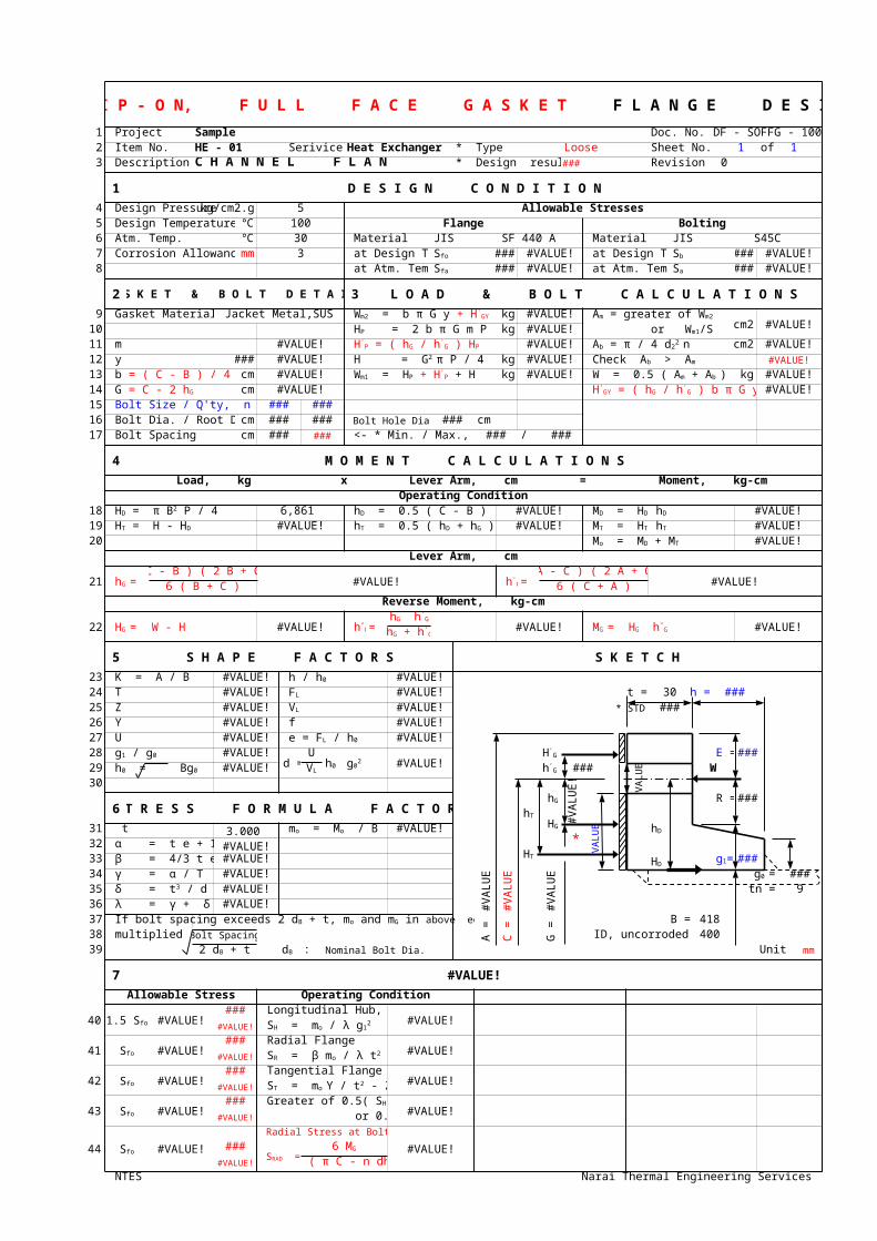
1 Project Sample Doc. No. DF - SOFFG - 1002 Item No. HE - 01 Serivice Heat Exchanger * Type Loose Sheet No. 1 of 13 Description S H E L L F L A N G E * Design result ### Revision 0
1 D E S I G N C O N D I T I O N
4 Design Pressure kg/cm2.g 10 Allowable Stresses5 Design Temperature ℃ 300 Flange Bolting6 Atm. Temp. ℃ 30 Material JIS SF 440 A Material JIS S45C7 Corrosion Allowance mm 3 at Design Temp. ### #VALUE! at Design Temp. ### #VALUE!8 at Atm. Temp. ### #VALUE! at Atm. Temp. ### #VALUE!
2 G A S K E T & B O L T D E T A I L S 3 L O A D & B O L T C A L C U L A T I O N S
9 Gasket Material Jacket Metal,SUS kg #VALUE!cm2 #VALUE!10 kg #VALUE!
11 m #VALUE! #VALUE! cm2 #VALUE!12 y ### #VALUE! kg #VALUE! #VALUE!
13 cm #VALUE! kg #VALUE! kg #VALUE!14 cm #VALUE! #VALUE!15 Bolt Size / Q'ty, n ### ###16 cm ### ### Bolt Hole Dia., dh ### cm17 Bolt Spacing cm ### ### <- * Min. / Max., TEMA ### / ###
4 M O M E N T C A L C U L A T I O N S
Load, kg x Lever Arm, cm = Moment, kg-cmOperating Condition
18 13,723 #VALUE! #VALUE!19 #VALUE! #VALUE! #VALUE!20 #VALUE!
Lever Arm, cm
21 =( C - B ) ( 2 B + C )
#VALUE! =( A - C ) ( 2 A + C )
#VALUE!6 ( B + C ) 6 ( C + A )Reverse Moment, kg-cm
22 = W - H #VALUE! = #VALUE! = #VALUE!
5 S H A P E F A C T O R S S K E T C H
23 K = A / B #VALUE! #VALUE!24 T #VALUE! #VALUE! t = 30 h = ###25 Z #VALUE! #VALUE! * STD ###26 Y #VALUE! f #VALUE!27 U #VALUE! #VALUE!28 #VALUE!
d =U
#VALUE!E = ###
29 #VALUE! ###
#VA
LUE
!
W30
#V
AL
UE
!
6 S T R E S S F O R M U L A F A C T O R SR = ###
31 t 3.000 #VALUE!*
#VA
LUE
!
32 #VALUE!###33 #VALUE!
34 #VALUE!
#V
AL
UE
!
#V
AL
UE
!
#V
AL
UE
!
###35 #VALUE! tn = 936 #VALUE!37
A =
C =
G =
B = 418 38 multiplied by Bolt Spacing ID, uncorroded 400 39 : Nominal Bolt Dia. Unit : mm
7 #VALUE!
Allowable Stress Operating Condition
40 #VALUE!### Longitudinal Hub,
#VALUE!#VALUE!
41 #VALUE!### Radial Flange
#VALUE!#VALUE!
42 #VALUE!### Tangential Flange
#VALUE!#VALUE!
43 #VALUE!###
#VALUE!#VALUE!
44 #VALUE!
Radial Stress at Bolt Circle
#VALUE!####VALUE!
NTES Narai Thermal Engineering Services
S L I P - O N, F U L L F A C E G A S K E T F L A N G E D E S I G N
Sfo Sb
Sfa Sa
Wm2 = b π G y + H'GY Am = greater of Wm2/Sa
HP = 2 b π G m P or Wm1/Sb
H'P = ( hG / h'
G ) HP Ab = π / 4 d22
n H = G2 π P / 4 Check Ab > Am
b = ( C - B ) / 4 Wm1 = HP + H'P + H W = 0.5 ( Am + Ab ) Sa
G = C - 2 hG H'GY = ( hG / h'
G ) b π G y
Bolt Dia. / Root Dia., d2
HD = π B2 P / 4 hD = 0.5 ( C - B ) MD = HD hD
HT = H - HD hT = 0.5 ( hD + hG ) MT = HT hT
Mo = MD + MT
hG h'G
HG h"G
hG h'G
MG HG h"GhG + h'
G
h / h0
FL
VL
e = FL / h0
g1 / g0h0 g0
2H'
G
h0 = Bg0 VL h'G
hG
hTHG mo = Mo / B hD
α = t e + 1HT g1= β = 4/3 t e + 1 HD
γ = α / T g0 = δ = t3 / d λ = γ + δ If bolt spacing exceeds 2 dB + t, mo and mG in above equations are
2 dB + t dB
1.5 Sfo SH = mo / λ g12
Sfo SR = β mo / λ t2
Sfo ST = mo Y / t2 - Z SR
Sfo
Greater of 0.5( SH + SR ) or 0.5( SH + ST )
Sfo SRAD =
6 MG
t2 ( π C - n dh )
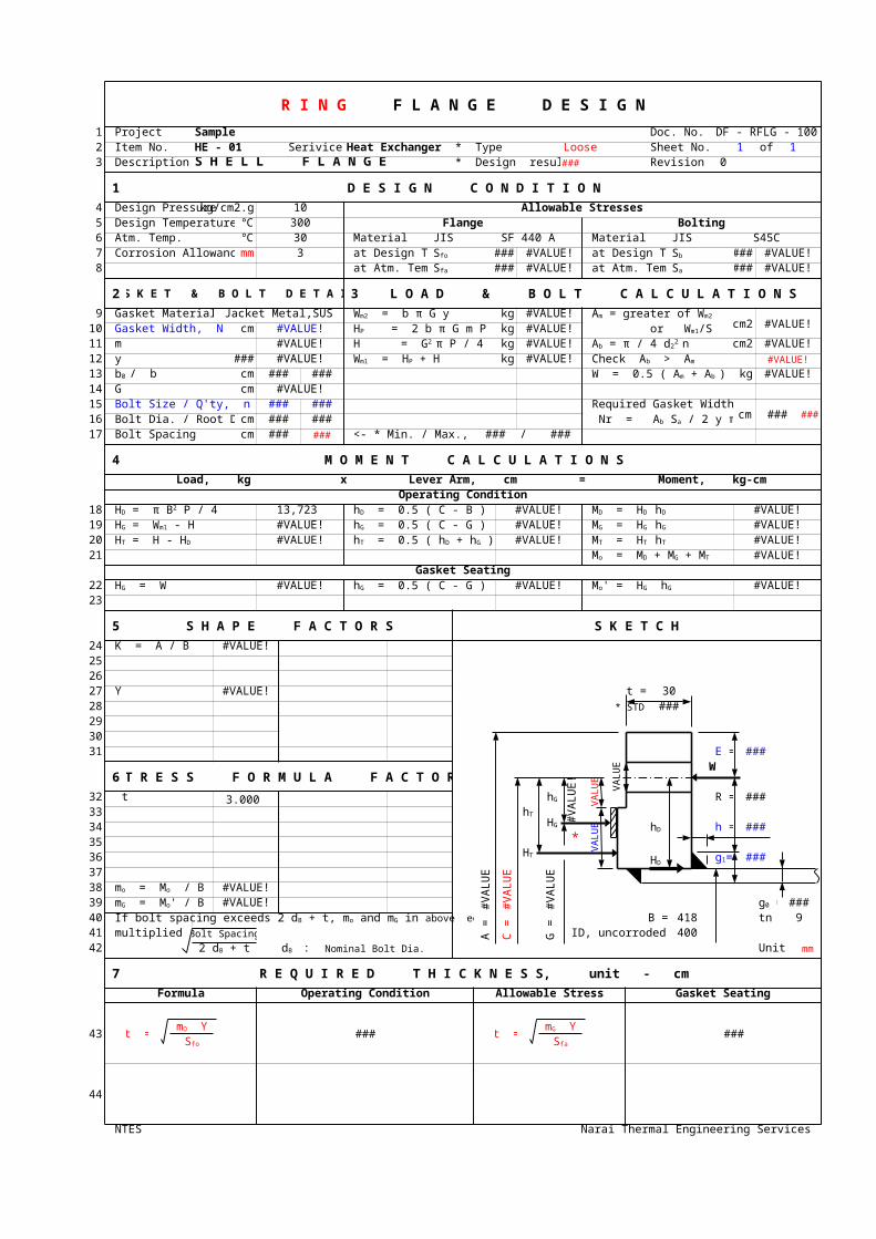
1 Project Sample Doc. No. DF - RFLG - 1002 Item No. HE - 01 Serivice Heat Exchanger * Type Loose Sheet No. 1 of 13 Description S H E L L F L A N G E * Design result ### Revision 0
1 D E S I G N C O N D I T I O N
4 Design Pressure kg/cm2.g 10 Allowable Stresses5 Design Temperature ℃ 300 Flange Bolting6 Atm. Temp. ℃ 30 Material JIS SF 440 A Material JIS S45C7 Corrosion Allowance mm 3 at Design Temp. ### #VALUE! at Design Temp. ### #VALUE!8 at Atm. Temp. ### #VALUE! at Atm. Temp. ### #VALUE!
2 G A S K E T & B O L T D E T A I L S 3 L O A D & B O L T C A L C U L A T I O N S
9 Gasket Material Jacket Metal,SUS kg #VALUE!cm2 #VALUE!10 Gasket Width, N cm #VALUE! kg #VALUE!
11 m #VALUE! kg #VALUE! cm2 #VALUE!12 y ### #VALUE! kg #VALUE! #VALUE!
13 / b cm ### ### kg #VALUE!14 G cm #VALUE!15 Bolt Size / Q'ty, n ### ### Required Gasket Width
cm ### ###16 cm ### ###17 Bolt Spacing cm ### ### <- * Min. / Max., TEMA ### / ###
4 M O M E N T C A L C U L A T I O N S
Load, kg x Lever Arm, cm = Moment, kg-cmOperating Condition
18 13,723 #VALUE! #VALUE!19 #VALUE! #VALUE! #VALUE!20 #VALUE! #VALUE! #VALUE!21 #VALUE!
Gasket Seating22 #VALUE! #VALUE! #VALUE!23
5 S H A P E F A C T O R S S K E T C H
24 K = A / B #VALUE!252627 Y #VALUE! t = 3028 * STD ###293031 E = ###
6 S T R E S S F O R M U L A F A C T O R S
#VA
LUE
!
W
#V
AL
UE
!
#VA
LUE
!
32 t 3.000 R = ###3334
*
#VA
LUE
!
h = ###3536 ###37
#V
AL
UE
!
#V
AL
UE
!
#V
AL
UE
!
38 #VALUE!39 #VALUE! ###40
A =
C =
G =
B = 418 tn = 941 multiplied by Bolt Spacing ID, uncorroded 400 42 : Nominal Bolt Dia. Unit : mm
7 R E Q U I R E D T H I C K N E S S, unit - cm
Formula Operating Condition Allowable Stress Gasket Seating
43 t = ### t = ###
44
NTES Narai Thermal Engineering Services
R I N G F L A N G E D E S I G N
Sfo Sb
Sfa Sa
Wm2 = b π G y Am = greater of Wm2/Sa
HP = 2 b π G m P or Wm1/Sb
H = G2 π P / 4 Ab = π / 4 d22
n Wm1 = HP + H Check Ab > Am
b0 W = 0.5 ( Am + Ab ) Sa
Bolt Dia. / Root Dia., d2 Nr = Ab Sa / 2 y π G < N
HD = π B2 P / 4 hD = 0.5 ( C - B ) MD = HD hD
HG = Wm1 - H hG = 0.5 ( C - G ) MG = HG hG
HT = H - HD hT = 0.5 ( hD + hG ) MT = HT hT
Mo = MD + MG + MT
HG = W hG = 0.5 ( C - G ) Mo' = HG hG
hG
hTHG hD
HT g1=HD
mo = Mo / B mG = Mo' / B g0 = If bolt spacing exceeds 2 dB + t, mo and mG in above equations are
2 dB + t dB
mO Y mG YSfo Sfa

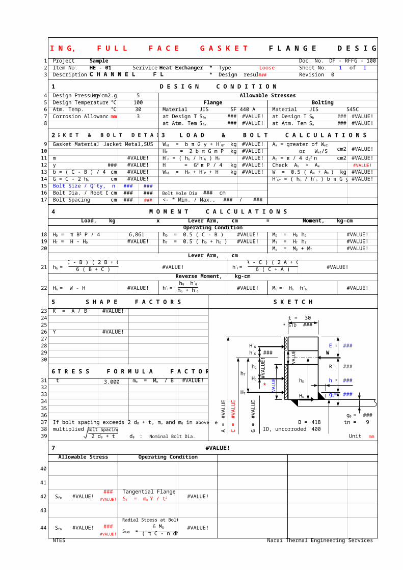
1 Project Sample Doc. No. DF - RFFG - 1002 Item No. HE - 01 Serivice Heat Exchanger * Type Loose Sheet No. 1 of 13 Description S H E L L F L A N G E * Design result ### Revision 0
1 D E S I G N C O N D I T I O N
4 Design Pressure kg/cm2.g 10 Allowable Stresses5 Design Temperature ℃ 300 Flange Bolting6 Atm. Temp. ℃ 30 Material JIS SF 440 A Material JIS S45C7 Corrosion Allowance mm 3 at Design Temp. ### #VALUE! at Design Temp. ### #VALUE!8 at Atm. Temp. ### #VALUE! at Atm. Temp. ### #VALUE!
2 G A S K E T & B O L T D E T A I L S 3 L O A D & B O L T C A L C U L A T I O N S
9 Gasket Material Jacket Metal,SUS kg #VALUE!cm2 #VALUE!10 kg #VALUE!
11 m #VALUE! #VALUE! cm2 #VALUE!12 y ### #VALUE! kg #VALUE! #VALUE!
13 b = ( C - B ) / 4 cm #VALUE! kg #VALUE! kg #VALUE!14 cm #VALUE! #VALUE!15 Bolt Size / Q'ty, n ### ###16 cm ### ### Bolt Hole Dia., dh ### cm17 Bolt Spacing cm ### ### <- * Min. / Max., TEMA ### / ###
4 M O M E N T C A L C U L A T I O N S
Load, kg x Lever Arm, cm = Moment, kg-cmOperating Condition
18 13,723 #VALUE! #VALUE!19 #VALUE! #VALUE! #VALUE!20 #VALUE!
Lever Arm, cm
21 =( C - B ) ( 2 B + C )
#VALUE! =( A - C ) ( 2 A + C )
#VALUE!6 ( B + C ) 6 ( C + A )Reverse Moment, kg-cm
22 = W - H #VALUE! = #VALUE! = #VALUE!
5 S H A P E F A C T O R S S K E T C H
23 K = A / B #VALUE!24 t = 3025 * STD ###26 Y #VALUE!2728 E = ###29 ###
#VA
LUE
!
W30
#V
AL
UE
!
6 S T R E S S F O R M U L A F A C T O R SR = ###
31 t 3.000 #VALUE!*
#VA
LUE
!
h = ###32
###3334
#V
AL
UE
!
#V
AL
UE
!
#V
AL
UE
!
3536 ###37
A =
C =
G =
B = 418 tn = 938 multiplied by Bolt Spacing ID, uncorroded 400 39 : Nominal Bolt Dia. Unit : mm
7 #VALUE!
Allowable Stress Operating Condition
40
41
42 #VALUE!### Tangential Flange
#VALUE!#VALUE!
43
44 #VALUE!
Radial Stress at Bolt Circle
#VALUE!####VALUE!
NTES Narai Thermal Engineering Services
R I N G, F U L L F A C E G A S K E T F L A N G E D E S I G N
Sfo Sb
Sfa Sa
Wm2 = b π G y + H'GY Am = greater of Wm2/Sa
HP = 2 b π G m P or Wm1/Sb
H'P = ( hG / h'
G ) HP Ab = π / 4 d22
n H = G2 π P / 4 Check Ab > Am
Wm1 = HP + H'P + H W = 0.5 ( Am + Ab ) Sa
G = C - 2 hG H'GY = ( hG / h'
G ) b π G y
Bolt Dia. / Root Dia., d2
HD = π B2 P / 4 hD = 0.5 ( C - B ) MD = HD hD
HT = H - HD hT = 0.5 ( hD + hG ) MT = HT hT
Mo = MD + MT
hG h'G
HG h"G
hG h'G
MG HG h"GhG + h'
G
H'G
h'G
hG
hTHG mo = Mo / B hD
HT g1=HD
g0 = If bolt spacing exceeds 2 dB + t, mo and mG in above equations are
2 dB + t dB
Sfo ST = mo Y / t2
Sfo SRAD =
6 MG
t2 ( π C - n dh )
H E A T E X C H A N G E R :
M E C H A N I C A L D E S I G N
Project Sample Doc. No. MD - HE - 100Item No. HE - 01 Sheet No. 0 of xService Heat Exchanger Revision 0
Part : Shell Flat Cover, Unstayed Flat Head
Code : * Welded
t = d C P / S E + α = 406 ### 10.0 / ### 1 + 3.0
= ### ### 30 mm used. ###
Where, C a factor depending upon the method of attachment of head, shell dimensions, and other items as listed in (d)0.33 m = 0.33 x ### = ### * min. 0.2 for * Welded
Where, m the ratio, tr / ts tr - required thickness of seamless channelts - nominal thickness of channel
= ### / 9 = ###
Code : * Formed & Welded
t = ( d C P / S E + α )100
= ( 406 0.17 10.0 / ### 1 + 3.0 )100
100 - r 100 - 15
= ### ### 0 mm used. ###
Where, C a factor depending upon the method of attachment of head, shell dimensions, and other items as listed in (d)0.17 for * Formed & Welded
NTES Narai Thermal Engineering Services
ASME Sec. VIII Div. 1 UG-34 ( c ) (2)
ASME Sec. VIII Div. 1 UG-34 ( c ) (2)
ts
dt
Sketch (a)
r = 3 t min.
W.L. T.L.
ts
d t
ts
d t
Sketch (e) Sketch (f)
H E A T E X C H A N G E R :
M E C H A N I C A L D E S I G N
Project Sample Doc. No. MD - HE - 100Item No. HE - 01 Sheet No. 0 of xSerivice Heat Exchanger Revision 0
Part : Channel or Bonnet
Code : * Circumferential Stress in the Logitudinal Joint
t =P R
+ α =5.0 203
+ 3.0 = ### ### 9 mm used. #VALUE!S E - 0.6 P ### 0.85 - 0.6 5.0
Where, t minimum required thickness of shell mmP internal design pressure kg/cm2.gR inside radius of the shell course under consideration mmS maximum allowable stress value ###E joint efficiency for, or the efficiency of, appropriate joint in cylindical or spherical shellsα corrosion allowance mm
NTES Narai Thermal Engineering Services
ASME Sec. VIII Div. 1 UG-27 ( c ) ( 1 )

M E C H A N I C A L D E S I G N
#VALUE!
Narai Thermal Engineering Services
H E A T E X C H A N G E R :
M E C H A N I C A L D E S I G N
Project Sample Doc. No. MD - HE - 100Item No. HE - 01 Sheet No. 0 of xService Heat Exchanger Revision 0
Part : Bonnet Cover
Code : * 2:1 Ellipsoidal Head, t / L >= 0.002
t = (P R
+ α )100
= (5.0 203
+ 3.0 )100
S E - 0.1 P 100 - r ### 1 - 0.1 5.0 100 - 15
= ### ### 9 mm used. ###
Where, t minimum required thickness of shell mmP internal design pressure kg/cm2.gR inside radius of the shell course under consideration mmS maximum allowable stress value ###E lowest efficiency of any joint in the head; for hemi-spherical heads, this includes head-to-shell joint;
α corrosion allowance mmr thickness reduction rate after forming %
Code : * 10 % Dished Head ( Torispherical Head ), t / L >= 0.002
t = (0.885 P L
+ α )100
= (0.885 5.0 406
+ 3.0 )100
S E - 0.1 P 100 - r ### 1 - 0.1 5.0 100 - 15
= ### ### 9 mm used. ###
Where, L inside spherical or crown radius mm
NTES Narai Thermal Engineering Services
ASME Sec. VIII Div. 1 UG-32 ( d )
for welded vessels, use the efficiency specified in UW-12
ASME Sec. VIII Div. 1 UG-32 ( e )
H E A T E X C H A N G E R :
M E C H A N I C A L D E S I G N
Project Sample Doc. No. MD - HE - 100Item No. HE - 01 Sheet No. 0 of xService Heat Exchanger Revision 0
Part : Channel Cover, Unstayed Flat HeadCode :
for operating conditions
t = d + dg
= ### 0.3 5.0 / ### 1 + 1.9 #VALUE! ### / ### 1 ### ^3 + 4= ### ### 35 mm used. ###
for gasket seating
t = ### 0.3 0.0 / ### 1 + 1.9 #VALUE! ### / ### 1 ### ^3 + 4= ### ### 35 mm used. ###
Where, t minimum required thickness of flat head mmd diameter measured as indicated in Fig. UG-34 = G mmC a factor depending upon the method of attachment of head, shell dimensions, and other items as listed in (d)
0.3 for * Bolted, Confined Gasket, Sketch (j)P internal design pressure kg/cm2.gS maximum allowable stress value in tension ###E joint efficiencyW ###
for operating conditions= Wm1 = H + Hp == 0.785 ### ^2 5.0 + ( 2 ### x 3.14 ### ### 5.0 ) = #VALUE!
for gasket seating= ( Am + Ab ) Sa / 2 * Wm2 = 3.14 b G y = 3.14 ### ### ### = #VALUE!= ( ### + ### ) ### / 2 = #VALUE!* required total bolt area, Am ### Ab -> ###
* required gasket width = Ab Sa / 2 y π G = ### ### gasket width, used = ### -> ###
Where, G diameter at location of gasket load reaction mmb effective gasket or joint-contact-surface seating width mmmy gasket or joint-contact-surface unit seating load ###Am total required cross-sectional area of bolts mm2Ab cross-sectional area of the bolts using the root diameter of the thread or
least diameter of unthreaded position, if less. mm2Sa allowable bolt stress at atmospheric temp. ###
gasket moment arm, equal to the radial distance from the center line of the bolts to the line of the gasket reactiondg groove depth plus corrosion allowance in excess of the groove depth mm
deflection limit * for checking excessive leakage through gasket between the cover and the pass partition plate.
Y =G
=###
( 0.0435 ### ^3 5.0 + 0.5 ### ### ####VALUE! 31 ^3
= ### ### 0.8 mm max. -> ###
Where, Y Channel cover deflection at the center mmE Modulus of elasticity at design temp. ###t Channel cover thickness mm
Allowable bolting stress at design temp. ###Sketch Bolting Data
t ### * STD
#VA
LUE
!
* TEMA Min. Nominal Bolt Size ###** ### Actual Bolt Dia. ### mm
Root Dia. ### mmGasket Width ###
#V
AL
UE
!
No. of Bolts ####VALUE!
#VA
LUE
! Bolt Spacing ### mm -> ###
G
#VA
LUE
!
#VA
LUE
!
#VA
LUE
!
400
" " , TEMA Min. ### mm### * " " , TEMA Max. ### mm
b0 = ###b = ###
NTES Narai Thermal Engineering Services
ASME Sec. VIII Div. 1 UG-34 ( c ) ( 2 ) * Bolted, Confined Gasket, Sketch (j)
C P / S E + 1.9 W hG / S E d3
total bolt load, Formula 2-5 (e)
0.785 G2 P + ( 2 b x 3.14 G m P )
gasket factor, Table 2-5.1
hG
TEMA RCB - 9.21
( 0.0435 G3 P + 0.5 SB Ab hG )E t3
SB
hG
H E A T E X C H A N G E R :
M E C H A N I C A L D E S I G N
Project Sample Doc. No. MD - HE - 100Item No. HE - 01 Sheet No. 0 of xService Heat Exchanger Revision 0
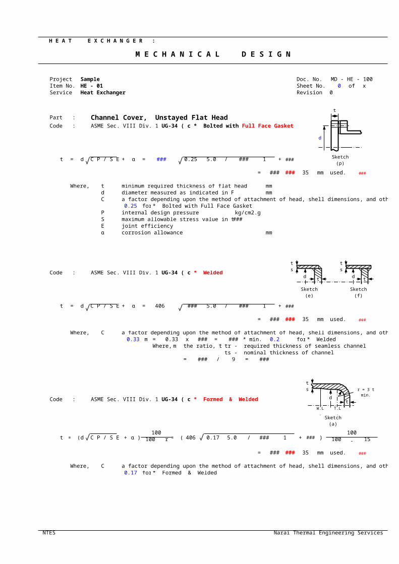
Part : Channel Cover, Unstayed Flat HeadCode :
t = d C P / S E + α = ### 0.25 5.0 / ### 1 + 3.0
= ### ### 35 mm used. ###
Where, t minimum required thickness of flat head mmd diameter measured as indicated in Fig. UG-34 mmC a factor depending upon the method of attachment of head, shell dimensions, and other items as listed in (d)
0.25 for * Bolted with Full Face GasketP internal design pressure kg/cm2.gS maximum allowable stress value in tension ###E joint efficiencyα corrosion allowance mm
Code : * Welded
t = d C P / S E + α = 406 ### 5.0 / ### 1 + 3.0
= ### ### 35 mm used. ###
Where, C a factor depending upon the method of attachment of head, shell dimensions, and other items as listed in (d)0.33 m = 0.33 x ### = ### * min. 0.2 for * Welded
Where, m the ratio, tr / ts tr - required thickness of seamless channelts - nominal thickness of channel
= ### / 9 = ###
Code : * Formed & Welded
t = ( d C P / S E + α )100
= ( 406 0.17 5.0 / ### 1 + 3.0 )100
100 - r 100 - 15
= ### ### 35 mm used. ###
Where, C a factor depending upon the method of attachment of head, shell dimensions, and other items as listed in (d)0.17 for * Formed & Welded
NTES Narai Thermal Engineering Services
ASME Sec. VIII Div. 1 UG-34 ( c ) (2) * Bolted with Full Face Gasket
ASME Sec. VIII Div. 1 UG-34 ( c ) (2)
ASME Sec. VIII Div. 1 UG-34 ( c ) (2)
ts
dt
Sketch (a)
r = 3 t min.
W.L. T.L.
ts
d t
ts
d t
Sketch (e) Sketch (f)
d
Sketch (p)
t

M E C H A N I C A L D E S I G N
#VALUE!
#VALUE!#VALUE!
)
Narai Thermal Engineering Services

M E C H A N I C A L D E S I G N
Narai Thermal Engineering Services
r = 3 t min.
1 Project Sample Doc. No. DF - WNFLG - 1002 Item No. HE - 01 Serivice Heat Exchanger Sheet No. 1 of 13 Description C H A N N E L F L A N G E * Design result ### Revision 0
1 D E S I G N C O N D I T I O N
4 Design Pressure kg/cm2.g 5 Allowable Stresses5 Design Temperature ℃ 100 Flange Bolting6 Atm. Temp. ℃ 30 Material JIS SF 440 A Material JIS S45C7 Corrosion Allowance mm 3 at Design Temp. ### #VALUE! at Design Temp. ### #VALUE!8 at Atm. Temp. ### #VALUE! at Atm. Temp. ### #VALUE!
2 G A S K E T & B O L T D E T A I L S 3 L O A D & B O L T C A L C U L A T I O N S
9 Gasket Material Jacket Metal,SUS kg #VALUE!cm2 #VALUE!10 Gasket Width, N cm #VALUE! kg #VALUE!
11 m #VALUE! kg #VALUE! cm2 #VALUE!12 y ### #VALUE! kg #VALUE! #VALUE!
13 / b cm ### ### kg #VALUE!14 G cm #VALUE!15 Bolt Size / Q'ty, n ### ### Required Gasket Width
cm ### ###16 cm ### ###17 Bolt Spacing cm ### ### <- * Min. / Max., TEMA ### / ###
4 M O M E N T C A L C U L A T I O N S
Load, kg x Lever Arm, cm = Moment, kg-cmOperating Condition
18 6,473 #VALUE! #VALUE!19 #VALUE! #VALUE! #VALUE!20 #VALUE! #VALUE! #VALUE!21 #VALUE!
Gasket Seating22 #VALUE! #VALUE! #VALUE!23
5 S H A P E F A C T O R S S K E T C H
24 K = A / B #VALUE! #VALUE!25 T #VALUE! F #VALUE!26 Z #VALUE! V #VALUE!27 Y #VALUE! f #VALUE! t = 30 h = ###28 U #VALUE! #VALUE! * STD ###29 #VALUE!
d =U
#VALUE!30 #VALUE! V31 E = ###
6 S T R E S S F O R M U L A F A C T O R S
#VA
LUE
!
W
#V
AL
UE
!
#VA
LUE
!
32 t 3.000 R = ###33 #VALUE!34 #VALUE!
*
#VA
LUE
!
35 #VALUE!###36 #VALUE!
37 #VALUE!
#V
AL
UE
!
#V
AL
UE
!
#V
AL
UE
!
38 #VALUE! ###39 #VALUE! tn = 940
A =
C =
G =
B = 406 41 multiplied by Bolt Spacing ID, uncorroded 400 42 : Nominal Bolt Dia. Unit : mm
7 #VALUE!
Allowable Stress Operating Condition Allowable Stress Gasket Seating
43 #VALUE!### Longitudinal Hub,
#VALUE! #VALUE!### Longitudinal Hub,
#VALUE!#VALUE! #VALUE!
44 #VALUE!### Radial Flange
#VALUE! #VALUE!### Radial Flange
#VALUE!#VALUE! #VALUE!
45 #VALUE!### Tangential Flange
#VALUE! #VALUE!### Tangential Flange
#VALUE!#VALUE! #VALUE!
46 #VALUE!###
#VALUE! #VALUE!###
#VALUE!#VALUE! #VALUE!
NTES Narai Thermal Engineering Services
W E L D I N G N E C K F L A N G E D E S I G N
Sfo Sb
Sfa Sa
Wm2 = b π G y Am = greater of Wm2/Sa
HP = 2 b π G m P or Wm1/Sb
H = G2 π P / 4 Ab = π / 4 d22
n Wm1 = HP + H Check Ab > Am
b0 W = 0.5 ( Am + Ab ) Sa
Bolt Dia. / Root Dia., d2 Nr = Ab Sa / 2 y π G < N
HD = π B2 P / 4 hD = R + 0.5 g1 MD = HD hD
HG = Wm1 - H hG = 0.5 ( C - G ) MG = HG hG
HT = H - HD hT = 0.5 ( R + g1 + hG ) MT = HT hT
Mo = MD + MG + MT
HG = W hG = 0.5 ( C - G ) Mo' = HG hG
h / h0
e = F / h0
g1 / g0h0 g0
2
h0 = Bg0
hG
α = t e + 1 hTHG
hD
β = 4/3 t e + 1 γ = α / T
HT HD g1= δ = t3 / d λ = γ + δ mo = Mo / B g0= mG = Mo' / B If bolt spacing exceeds 2 dB + t, mo and mG in above equations are
2 dB + t dB
1.5 Sfo 1.5 Sfa SH = f mo / λ g12 SH = f mG / λ g1
2
Sfo Sfa SR = β mo / λ t2 SR = β mG / λ t2
Sfo Sfa ST = mo Y / t2 - Z SR ST = mG Y / t2 - Z SR
Sfo
Greater of 0.5( SH + SR )Sfa
Greater of 0.5( SH + SR ) or 0.5( SH + ST ) or 0.5( SH + ST )

1 Project Sample Doc. No. DF - SOFLG - 1002 Item No. HE - 01 Serivice Heat Exchanger * Type Loose Sheet No. 1 of 13 Description C H A N N E L F L A N G E * Design result ### Revision 0
1 D E S I G N C O N D I T I O N
4 Design Pressure kg/cm2.g 5 Allowable Stresses5 Design Temperature ℃ 100 Flange Bolting6 Atm. Temp. ℃ 30 Material JIS SF 440 A Material JIS S45C7 Corrosion Allowance mm 3 at Design Temp. ### #VALUE! at Design Temp. ### #VALUE!8 at Atm. Temp. ### #VALUE! at Atm. Temp. ### #VALUE!
2 G A S K E T & B O L T D E T A I L S 3 L O A D & B O L T C A L C U L A T I O N S
9 Gasket Material Jacket Metal,SUS kg #VALUE!cm2 #VALUE!10 Gasket Width, N cm #VALUE! kg #VALUE!
11 m #VALUE! kg #VALUE! cm2 #VALUE!12 y ### #VALUE! kg #VALUE! #VALUE!
13 / b cm ### ### kg #VALUE!14 G cm #VALUE!15 Bolt Size / Q'ty, n ### ### Required Gasket Width
cm ### ###16 cm ### ###17 Bolt Spacing cm ### ### <- * Min. / Max., TEMA ### / ###
4 M O M E N T C A L C U L A T I O N S
Load, kg x Lever Arm, cm = Moment, kg-cmOperating Condition
18 6,861 #VALUE! #VALUE!19 #VALUE! #VALUE! #VALUE!20 #VALUE! #VALUE! #VALUE!21 #VALUE!
Gasket Seating22 #VALUE! #VALUE! #VALUE!23
5 S H A P E F A C T O R S S K E T C H
24 K = A / B #VALUE! #VALUE!25 T #VALUE! #VALUE!26 Z #VALUE! #VALUE!27 Y #VALUE! f #VALUE! t = 30 h = ###28 U #VALUE! #VALUE! * STD ###29 #VALUE!
d =U
#VALUE!30 #VALUE!31 E = ###
6 S T R E S S F O R M U L A F A C T O R S
#VA
LUE
!
W
#V
AL
UE
!
#VA
LUE
!
32 t 3.000 R = ###33 #VALUE!34 #VALUE!
*
#VA
LUE
!
35 #VALUE!###36 #VALUE!
37 #VALUE!
#V
AL
UE
!
#V
AL
UE
!
#V
AL
UE
!
###38 #VALUE! tn = 939 #VALUE!40
A =
C =
G =
B = 418 41 multiplied by Bolt Spacing ID, uncorroded 400 42 : Nominal Bolt Dia. Unit : mm
7 #VALUE!
Allowable Stress Operating Condition Allowable Stress Gasket Seating
43 #VALUE!### Longitudinal Hub,
#VALUE! #VALUE!### Longitudinal Hub,
#VALUE!#VALUE! #VALUE!
44 #VALUE!### Radial Flange
#VALUE! #VALUE!### Radial Flange
#VALUE!#VALUE! #VALUE!
45 #VALUE!### Tangential Flange
#VALUE! #VALUE!### Tangential Flange
#VALUE!#VALUE! #VALUE!
46 #VALUE!###
#VALUE! #VALUE!###
#VALUE!#VALUE! #VALUE!
NTES Narai Thermal Engineering Services
S L I P - O N F L A N G E D E S I G N
Sfo Sb
Sfa Sa
Wm2 = b π G y Am = greater of Wm2/Sa
HP = 2 b π G m P or Wm1/Sb
H = G2 π P / 4 Ab = π / 4 d22
n Wm1 = HP + H Check Ab > Am
b0 W = 0.5 ( Am + Ab ) Sa
Bolt Dia. / Root Dia., d2 Nr = Ab Sa / 2 y π G < N
HD = π B2 P / 4 hD = 0.5 ( C - B ) MD = HD hD
HG = Wm1 - H hG = 0.5 ( C - G ) MG = HG hG
HT = H - HD hT = 0.5 ( hD + hG ) MT = HT hT
Mo = MD + MG + MT
HG = W hG = 0.5 ( C - G ) Mo' = HG hG
h / h0
FL
VL
e = FL / h0
g1 / g0h0 g0
2
h0 = Bg0 VL
hG
α = t e + 1 hTHG β = 4/3 t e + 1 hD
γ = α / THT g1= δ = t3 / d HD
λ = γ + δ g0 = mo = Mo / B mG = Mo' / B If bolt spacing exceeds 2 dB + t, mo and mG in above equations are
2 dB + t dB
1.5 Sfo 1.5 Sfa SH = mo / λ g12 SH = mG / λ g1
2
Sfo Sfa SR = β mo / λ t2 SR = β mG / λ t2
Sfo Sfa ST = mo Y / t2 - Z SR ST = mG Y / t2 - Z SR
Sfo
Greater of 0.5( SH + SR )Sfa
Greater of 0.5( SH + SR ) or 0.5( SH + ST ) or 0.5( SH + ST )
1 Project Sample Doc. No. DF - SOFFG - 1002 Item No. HE - 01 Serivice Heat Exchanger * Type Loose Sheet No. 1 of 13 Description C H A N N E L F L A N G E * Design result ### Revision 0
1 D E S I G N C O N D I T I O N
4 Design Pressure kg/cm2.g 5 Allowable Stresses5 Design Temperature ℃ 100 Flange Bolting6 Atm. Temp. ℃ 30 Material JIS SF 440 A Material JIS S45C7 Corrosion Allowance mm 3 at Design Temp. ### #VALUE! at Design Temp. ### #VALUE!8 at Atm. Temp. ### #VALUE! at Atm. Temp. ### #VALUE!
2 G A S K E T & B O L T D E T A I L S 3 L O A D & B O L T C A L C U L A T I O N S
9 Gasket Material Jacket Metal,SUS kg #VALUE!cm2 #VALUE!10 kg #VALUE!
11 m #VALUE! #VALUE! cm2 #VALUE!12 y ### #VALUE! kg #VALUE! #VALUE!
13 cm #VALUE! kg #VALUE! kg #VALUE!14 cm #VALUE! #VALUE!15 Bolt Size / Q'ty, n ### ###16 cm ### ### Bolt Hole Dia., dh ### cm17 Bolt Spacing cm ### ### <- * Min. / Max., TEMA ### / ###
4 M O M E N T C A L C U L A T I O N S
Load, kg x Lever Arm, cm = Moment, kg-cmOperating Condition
18 6,861 #VALUE! #VALUE!19 #VALUE! #VALUE! #VALUE!20 #VALUE!
Lever Arm, cm
21 =( C - B ) ( 2 B + C )
#VALUE! =( A - C ) ( 2 A + C )
#VALUE!6 ( B + C ) 6 ( C + A )Reverse Moment, kg-cm
22 = W - H #VALUE! = #VALUE! = #VALUE!
5 S H A P E F A C T O R S S K E T C H
23 K = A / B #VALUE! #VALUE!24 T #VALUE! #VALUE! t = 30 h = ###25 Z #VALUE! #VALUE! * STD ###26 Y #VALUE! f #VALUE!27 U #VALUE! #VALUE!28 #VALUE!
d =U
#VALUE!E = ###
29 #VALUE! ###
#VA
LUE
!
W30
#V
AL
UE
!
6 S T R E S S F O R M U L A F A C T O R SR = ###
31 t 3.000 #VALUE!*
#VA
LUE
!
32 #VALUE!###33 #VALUE!
34 #VALUE!
#V
AL
UE
!
#V
AL
UE
!
#V
AL
UE
!
###35 #VALUE! tn = 936 #VALUE!37
A =
C =
G =
B = 418 38 multiplied by Bolt Spacing ID, uncorroded 400 39 : Nominal Bolt Dia. Unit : mm
7 #VALUE!
Allowable Stress Operating Condition
40 #VALUE!### Longitudinal Hub,
#VALUE!#VALUE!
41 #VALUE!### Radial Flange
#VALUE!#VALUE!
42 #VALUE!### Tangential Flange
#VALUE!#VALUE!
43 #VALUE!###
#VALUE!#VALUE!
44 #VALUE!
Radial Stress at Bolt Circle
#VALUE!####VALUE!
NTES Narai Thermal Engineering Services
S L I P - O N, F U L L F A C E G A S K E T F L A N G E D E S I G N
Sfo Sb
Sfa Sa
Wm2 = b π G y + H'GY Am = greater of Wm2/Sa
HP = 2 b π G m P or Wm1/Sb
H'P = ( hG / h'
G ) HP Ab = π / 4 d22
n H = G2 π P / 4 Check Ab > Am
b = ( C - B ) / 4 Wm1 = HP + H'P + H W = 0.5 ( Am + Ab ) Sa
G = C - 2 hG H'GY = ( hG / h'
G ) b π G y
Bolt Dia. / Root Dia., d2
HD = π B2 P / 4 hD = 0.5 ( C - B ) MD = HD hD
HT = H - HD hT = 0.5 ( hD + hG ) MT = HT hT
Mo = MD + MT
hG h'G
HG h"G
hG h'G
MG HG h"GhG + h'
G
h / h0
FL
VL
e = FL / h0
g1 / g0h0 g0
2H'
G
h0 = Bg0 VL h'G
hG
hTHG mo = Mo / B hD
α = t e + 1HT g1= β = 4/3 t e + 1 HD
γ = α / T g0 = δ = t3 / d λ = γ + δ If bolt spacing exceeds 2 dB + t, mo and mG in above equations are
2 dB + t dB
1.5 Sfo SH = mo / λ g12
Sfo SR = β mo / λ t2
Sfo ST = mo Y / t2 - Z SR
Sfo
Greater of 0.5( SH + SR ) or 0.5( SH + ST )
Sfo SRAD =
6 MG
t2 ( π C - n dh )

1 Project Sample Doc. No. DF - RFLG - 1002 Item No. HE - 01 Serivice Heat Exchanger * Type Loose Sheet No. 1 of 13 Description C H A N N E L F L A N G E * Design result ### Revision 0
1 D E S I G N C O N D I T I O N
4 Design Pressure kg/cm2.g 5 Allowable Stresses5 Design Temperature ℃ 100 Flange Bolting6 Atm. Temp. ℃ 30 Material JIS SF 440 A Material JIS S45C7 Corrosion Allowance mm 3 at Design Temp. ### #VALUE! at Design Temp. ### #VALUE!8 at Atm. Temp. ### #VALUE! at Atm. Temp. ### #VALUE!
2 G A S K E T & B O L T D E T A I L S 3 L O A D & B O L T C A L C U L A T I O N S
9 Gasket Material Jacket Metal,SUS kg #VALUE!cm2 #VALUE!10 Gasket Width, N cm #VALUE! kg #VALUE!
11 m #VALUE! kg #VALUE! cm2 #VALUE!12 y ### #VALUE! kg #VALUE! #VALUE!
13 / b cm ### ### kg #VALUE!14 G cm #VALUE!15 Bolt Size / Q'ty, n ### ### Required Gasket Width
cm ### ###16 cm ### ###17 Bolt Spacing cm ### ### <- * Min. / Max., TEMA ### / ###
4 M O M E N T C A L C U L A T I O N S
Load, kg x Lever Arm, cm = Moment, kg-cmOperating Condition
18 6,861 #VALUE! #VALUE!19 #VALUE! #VALUE! #VALUE!20 #VALUE! #VALUE! #VALUE!21 #VALUE!
Gasket Seating22 #VALUE! #VALUE! #VALUE!23
5 S H A P E F A C T O R S S K E T C H
24 K = A / B #VALUE!252627 Y #VALUE! t = 3028 * STD ###293031 E = ###
6 S T R E S S F O R M U L A F A C T O R S
#VA
LUE
!
W
#V
AL
UE
!
#VA
LUE
!
32 t 3.000 R = ###3334
*
#VA
LUE
!
h = ###3536 ###37
#V
AL
UE
!
#V
AL
UE
!
#V
AL
UE
!
38 #VALUE!39 #VALUE! ###40
A =
C =
G =
B = 418 tn = 941 multiplied by Bolt Spacing ID, uncorroded 400 42 : Nominal Bolt Dia. Unit : mm
7 R E Q U I R E D T H I C K N E S S, unit - cm
Formula Operating Condition Allowable Stress Gasket Seating
43 t = ### t = ###
44
NTES Narai Thermal Engineering Services
R I N G F L A N G E D E S I G N
Sfo Sb
Sfa Sa
Wm2 = b π G y Am = greater of Wm2/Sa
HP = 2 b π G m P or Wm1/Sb
H = G2 π P / 4 Ab = π / 4 d22
n Wm1 = HP + H Check Ab > Am
b0 W = 0.5 ( Am + Ab ) Sa
Bolt Dia. / Root Dia., d2 Nr = Ab Sa / 2 y π G < N
HD = π B2 P / 4 hD = 0.5 ( C - B ) MD = HD hD
HG = Wm1 - H hG = 0.5 ( C - G ) MG = HG hG
HT = H - HD hT = 0.5 ( hD + hG ) MT = HT hT
Mo = MD + MG + MT
HG = W hG = 0.5 ( C - G ) Mo' = HG hG
hG
hTHG hD
HT g1=HD
mo = Mo / B mG = Mo' / B g0 = If bolt spacing exceeds 2 dB + t, mo and mG in above equations are
2 dB + t dB
mO Y mG YSfo Sfa

1 Project Sample Doc. No. DF - RFFG - 1002 Item No. HE - 01 Serivice Heat Exchanger * Type Loose Sheet No. 1 of 13 Description C H A N N E L F L A N G E * Design result ### Revision 0
1 D E S I G N C O N D I T I O N
4 Design Pressure kg/cm2.g 5 Allowable Stresses5 Design Temperature ℃ 100 Flange Bolting6 Atm. Temp. ℃ 30 Material JIS SF 440 A Material JIS S45C7 Corrosion Allowance mm 3 at Design Temp. ### #VALUE! at Design Temp. ### #VALUE!8 at Atm. Temp. ### #VALUE! at Atm. Temp. ### #VALUE!
2 G A S K E T & B O L T D E T A I L S 3 L O A D & B O L T C A L C U L A T I O N S
9 Gasket Material Jacket Metal,SUS kg #VALUE!cm2 #VALUE!10 kg #VALUE!
11 m #VALUE! #VALUE! cm2 #VALUE!12 y ### #VALUE! kg #VALUE! #VALUE!
13 b = ( C - B ) / 4 cm #VALUE! kg #VALUE! kg #VALUE!14 cm #VALUE! #VALUE!15 Bolt Size / Q'ty, n ### ###16 cm ### ### Bolt Hole Dia., dh ### cm17 Bolt Spacing cm ### ### <- * Min. / Max., TEMA ### / ###
4 M O M E N T C A L C U L A T I O N S
Load, kg x Lever Arm, cm = Moment, kg-cmOperating Condition
18 6,861 #VALUE! #VALUE!19 #VALUE! #VALUE! #VALUE!20 #VALUE!
Lever Arm, cm
21 =( C - B ) ( 2 B + C )
#VALUE! =( A - C ) ( 2 A + C )
#VALUE!6 ( B + C ) 6 ( C + A )Reverse Moment, kg-cm
22 = W - H #VALUE! = #VALUE! = #VALUE!
5 S H A P E F A C T O R S S K E T C H
23 K = A / B #VALUE!24 t = 3025 * STD ###26 Y #VALUE!2728 E = ###29 ###
#VA
LUE
!
W30
#V
AL
UE
!
6 S T R E S S F O R M U L A F A C T O R SR = ###
31 t 3.000 #VALUE!*
#VA
LUE
!
h = ###32
###3334
#V
AL
UE
!
#V
AL
UE
!
#V
AL
UE
!
3536 ###37
A =
C =
G =
B = 418 tn = 938 multiplied by Bolt Spacing ID, uncorroded 400 39 : Nominal Bolt Dia. Unit : mm
7 #VALUE!
Allowable Stress Operating Condition
40
41
42 #VALUE!### Tangential Flange
#VALUE!#VALUE!
43
44 #VALUE!
Radial Stress at Bolt Circle
#VALUE!####VALUE!
NTES Narai Thermal Engineering Services
R I N G, F U L L F A C E G A S K E T F L A N G E D E S I G N
Sfo Sb
Sfa Sa
Wm2 = b π G y + H'GY Am = greater of Wm2/Sa
HP = 2 b π G m P or Wm1/Sb
H'P = ( hG / h'
G ) HP Ab = π / 4 d22
n H = G2 π P / 4 Check Ab > Am
Wm1 = HP + H'P + H W = 0.5 ( Am + Ab ) Sa
G = C - 2 hG H'GY = ( hG / h'
G ) b π G y
Bolt Dia. / Root Dia., d2
HD = π B2 P / 4 hD = 0.5 ( C - B ) MD = HD hD
HT = H - HD hT = 0.5 ( hD + hG ) MT = HT hT
Mo = MD + MT
hG h'G
HG h"G
hG h'G
MG HG h"GhG + h'
G
H'G
h'G
hG
hTHG mo = Mo / B hD
HT g1=HD
g0 = If bolt spacing exceeds 2 dB + t, mo and mG in above equations are
2 dB + t dB
Sfo ST = mo Y / t2
Sfo SRAD =
6 MG
t2 ( π C - n dh )

H E A T E X C H A N G E R :
M E C H A N I C A L D E S I G N
Project Sample Doc. No. MD - HE - 100Item No. HE - 01 Sheet No. 0 of xService Heat Exchanger Revision 0
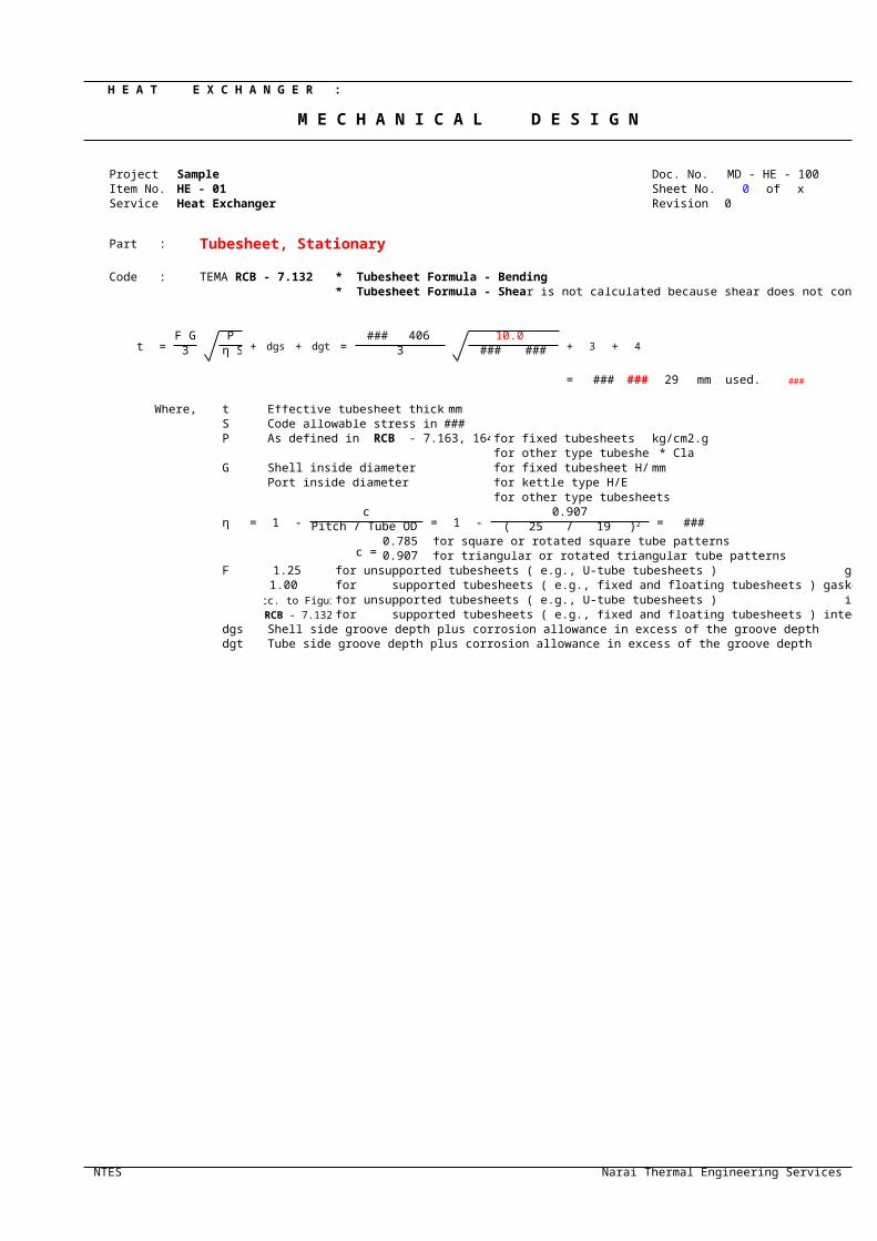
Part : Tubesheet, Stationary
Code : * Tubesheet Formula - Bending
t =F G P
+ dgs + dgt =### 406 10.0
+ 3 + 43 η S 3 0.476 ###
= ### ### 29 mm used. ###
Where, t Effective tubesheet thickness mmS Code allowable stress in tension ###P for fixed tubesheets kg/cm2.g
for other type tubesheets * ClassG Shell inside diameter for fixed tubesheet H/E mm
Port inside diameter for kettle type H/Efor other type tubesheets
η = 1 -c
= 1 -0.907
= 0.476 ( 25 / 19
c =0.785 for square or rotated square tube patterns0.907 for triangular or rotated triangular tube patterns
F 1.25 for unsupported tubesheets ( e.g., U-tube tubesheets ) gasketed both sides1.00 for supported tubesheets ( e.g., fixed and floating tubesheets ) gasketed both sides
acc. to Figure for unsupported tubesheets ( e.g., U-tube tubesheets ) integral with either or both sidesfor supported tubesheets ( e.g., fixed and floating tubesheets ) integral with either or both sides
dgs Shell side groove depth plus corrosion allowance in excess of the groove depthdgt Tube side groove depth plus corrosion allowance in excess of the groove depth
NTES Narai Thermal Engineering Services
TEMA RCB - 7.132* Tubesheet Formula - Shear is not calculated because shear does not control the design.
As defined in RCB - 7.163, 164 or 165
( Pitch / Tube OD )2 )2
RCB - 7.132

M E C H A N I C A L D E S I G N
Narai Thermal Engineering Services

H E A T E X C H A N G E R : Doc. No. MD - HE - 100
M E C H A N I C A L D E S I G N Revision 0 Sheet No. 0 of x
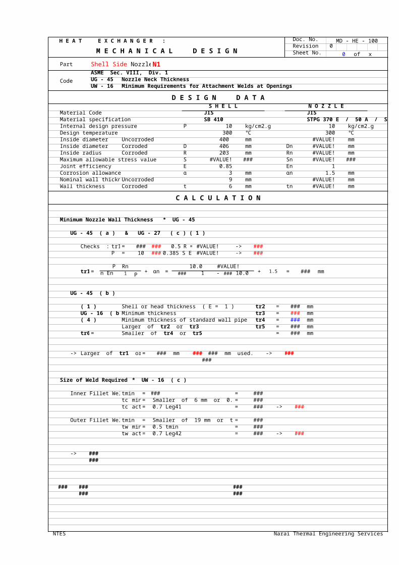
Part N1
Code
ASME Sec. VIII, Div. 1UG - 45 Nozzle Neck ThicknessUW - 16 Minimum Requirements for Attachment Welds at Openings
D E S I G N D A T AS H E L L N O Z Z L E
Material Code JIS JISMaterial specification SB 410 STPG 370 E / 50 A / Sch.160Internal design pressure P 10 kg/cm2.g 10 kg/cm2.gDesign temperature 300 ℃ 300 ℃Inside diameter Uncorroded 400 mm #VALUE! mmInside diameter Corroded D 406 mm Dn #VALUE! mmInside radius Corroded R 203 mm Rn #VALUE! mmMaximum allowable stress value S #VALUE! ### Sn #VALUE! ###Joint efficiency E 0.85 En 1Corrosion allowance α 3 mm αn 1.5 mmNominal wall thickness Uncorroded 9 mm #VALUE! mmWall thickness Corroded t 6 mm tn #VALUE! mm
C A L C U L A T I O N
Minimum Nozzle Wall Thickness * UG - 45
UG - 45 ( a ) & UG - 27 ( c ) ( 1 )
Checks : tr1 = ### ### 0.5 R = #VALUE! -> ###P = 10 ### 0.385 S E = #VALUE! -> ###
tr1 =P Rn
+ αn =10.0 #VALUE!
+ 1.5 = ### mmSn En - 0.6 P ### 1 - 0.6 10.0
UG - 45 ( b )
( 1 ) Shell or head thickness ( E = 1 ) tr2 = ### mmUG - 16 ( b ) Minimum thickness tr3 = ### mm( 4 ) Minimum thickness of standard wall pipe tr4 = ### mm
tr5 = ### mmtr6 = = ### mm
-> = ### mm ### ### mm used. -> ######
Size of Weld Required * UW - 16 ( c )
Inner Fillet Weld tmin = ### = ###tc min = Smaller of 6 mm or 0.7 tmin = ###tc act = 0.7 Leg41 = ### -> ###
Outer Fillet Weld tmin = Smaller of 19 mm or te or t = ###tw min = 0.5 tmin = ###tw act = 0.7 Leg42 = ### -> ###
-> ######
### ### ###### ###
NTES Narai Thermal Engineering Services
Shell Side Nozzle >
Larger of tr2 or tr3Smaller of tr4 or tr5
Larger of tr1 or tr6

H E A T E X C H A N G E R : Doc. No. MD - HE - 100
M E C H A N I C A L D E S I G N Revision 0 Sheet No. 1 of x
Part Shell Side Nozzle > N1
Code UG - 37 Reinforcements required for Openings in Shells and Formed Heads
D E S I G N D A T ANozzle Placemenent InsertedFinished diameter of circular opening = Dn d ### mmCorrction factor F 1Required thickness of a seamless shell or head tr ### mmRequired thickness of a seamless nozzle wall trn ### mm
Allowable stress value in tension, Nozzle Sn ### ###Allowable stress value in tension, Vessel Sv ### ###
1.0 = Sn/Sv fr1 ###1.0 = Sn/Sv fr2 ###
E1 1Pad material code ###Pad material specification ###Pad O.D. ### mmPad thickness te ### mm
Allowable stress value in reinforcing element Sp ### ###1.0 =( lesser of Sn or Sp )/ Sv fr3 ### ###
1.0 = Sp/Sv fr4 ###Size of Weld Required * UW - 16 ( c )
Leg41 ### mm * Min. ###Leg42 ### mm * Min. ###Leg43 - N/A - mm * Min.
Limit of reinforcement ### mm * Larger of d or Rn + tn + tOutside diameter of reinforcing element Dp ### mm
C A L C U L A T I O N
= = d tr F + 2 tn tr F ( 1 - fr1 )= #VALUE! mm2
== Larger of d ( E1 t - F tr ) - 2 tn ( E1 t - F tr ) ( 1 - fr1 ) or 2 ( t + tn ) ( E1 t - F tr ) - 2 tn ( E1 t - F tr ) ( 1 - fr1 )= #VALUE! mm2
= = Smaller of ###= #VALUE! mm2
= = Smallest of 5 t ti fr2, 5 ti ti fr2 or 2 h ti fr2= - N/A - mm2
= = outward nozzle weld = ###= #VALUE! mm2
= = outer element weld = (leg)^2 fr4= #VALUE! mm2
= = inward nozzle weld = (leg)^2 fr2= - N/A - mm2
= = ( Dp - d - 2 tn ) te fr4= #VALUE! mm2
### #VALUE! ### A = #VALUE! ### ###
NTES Narai Thermal Engineering Services
Strength reduction factor, ≤Strength reduction factor, ≤
Strength reduction factor, ≤Strength reduction factor, ≤
* UG - 40
A, Area required
A1, Area available in shell
A2, Area available in nozzle projecting outward
A3, Aea available in inward nozzle
A41, Area available in outward weld
A42, Area available in outer weld
A43, Area available in inward weld
A5, Area available in element
tn RnDp
trn
tr
c
hti
d
te
t
* 1 : Smaller of 2.5 t or 2.5 tn + te
* 2 : Smallest of h, 2.5 t, or 2.5 ti
Larger of
d or Rn + tn + t
For nozzle wall inserted
Larger of
d or Rn + tn + t
For nozzle wall abutting
the vessel wallthrough the vessel wall
* 1
* 2

H E A T E X C H A N G E R : Doc. No. MD - HE - 100
M E C H A N I C A L D E S I G N Revision 0 Sheet No. 2 of x
Part Shell Side Nozzle > N1
Code UG - 41 Strength of Reinforcement
C A L C U L A T I O N
Allowable Unit Stresses * UG - 45 ( c ) & UW - 15 ( c )
Fillet Weld Shear Sfs = 0.49 x #VALUE! = #VALUE! ###Nozzle Wall Shear Sns = 0.7 x #VALUE! = #VALUE! ###Groove Weld Tension Sgt = 0.74 x #VALUE! = #VALUE! ###Groove Weld Shear Sgs = 0.6 x #VALUE! = #VALUE! ###
Strength of Connection Elements * Dimensions are in ###
Inner Fillet Weld Shear(a) = π / 2 x Nozzle OD x Weld Leg x Sfs
= π / 2 x ### x ### x #VALUE! = #VALUE! ### = #VALUE! NNozzle Wall Shear(b) = π / 2 x Mean Nozzle Dia. x tn x Sns
= π / 2 x ### x ### x #VALUE! = #VALUE! ### = #VALUE! NGroove Weld Tension(c) = π / 2 x Nozzle OD x t x Sgt
= π / 2 x ### x ### x #VALUE! = #VALUE! ### = #VALUE! NOuter Fillet Weld Shear(d) = π / 2 x Pad OD x Weld Leg x Sfs
= π / 2 x ### x ### x #VALUE! = #VALUE! ### = #VALUE! NUpper Groove Weld Tension(e) = π / 2 x Nozzle OD x te x Sgt
= π / 2 x ### x ### x #VALUE! = #VALUE! ### = #VALUE! NLower Fillet Weld Shear(f) = π / 2 x Nozzle OD x Weld Leg x Sfs
= π / 2 x ### x - N/A - x #VALUE! = - N/A - ### = - N/A - N
Load to be carried by Welds * UG - 41 ( b ) ( 1 ) & ( 2 )
Weld Load for Strength Path 1 - 1W1-1 = ( A2 + A5 + A41 + A42 ) Sv = #VALUE! ### = #VALUE! NWeld Load for Strength Path 2 - 2W2-2 = ( A2 + A3 + A41 + A43 + 2 tn t fr1 ) Sv = #VALUE! ### = #VALUE! NWeld Load for Strength Path 3 - 3W3-3 = ( A2 + A3 + A5 + A41 + A42 + A43 + 2 tn t fr1 ) Sv = #VALUE! ### = #VALUE! NTotal Weld LoadW = [ A - A1 + 2 tn fr1 ( E1 t - F tr ) ] Sv = #VALUE! ### = #VALUE! N
Check Strength Paths * UG - 41 ( b ) ( 1 ) & ( 2 )
Path 1-1 (d) + (b) = #VALUE! + #VALUE! = #VALUE! N -> ###Load for Path 1-1 = = #VALUE! N
Path 2-2 (a) + (c) + (e) = #VALUE! + #VALUE! + #VALUE! = #VALUE! N -> ###Load for Path 2-2 = = #VALUE! N
Path 3-3 (d) + (c) = #VALUE! + #VALUE! = #VALUE! N -> ###Load for Path 3-3 = = #VALUE! N
-> ### ###
NTES Narai Thermal Engineering Services
Smaller of W1-1 or W
Smaller of W2-2 or W
Smaller of W3-3 or W

MD - HE - 100
N1
D E S I G N D A T A
STPG 370 E / 50 A / Sch.160
C A L C U L A T I O N
Narai Thermal Engineering Services

MD - HE - 100
N1
D E S I G N D A T A
C A L C U L A T I O N
Narai Thermal Engineering Services
te
For nozzle wall abutting
the vessel wall

MD - HE - 100
N1
C A L C U L A T I O N
Narai Thermal Engineering Services

H E A T E X C H A N G E R : Doc. No. MD - HE - 100
M E C H A N I C A L D E S I G N Revision 0 Sheet No. 0 of x
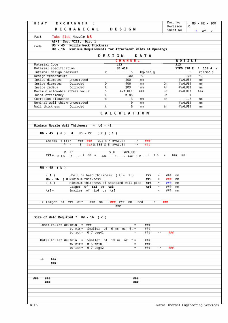
Part N3
Code
ASME Sec. VIII, Div. 1UG - 45 Nozzle Neck ThicknessUW - 16 Minimum Requirements for Attachment Welds at Openings
D E S I G N D A T AC H A N N E L N O Z Z L E
Material Code JIS JISMaterial specification SB 410 STPG 370 E / 150 A / Sch.80Internal design pressure P 5 kg/cm2.g 5 kg/cm2.gDesign temperature 100 ℃ 100 ℃Inside diameter Uncorroded 400 mm #VALUE! mmInside diameter Corroded D 406 mm Dn #VALUE! mmInside radius Corroded R 203 mm Rn #VALUE! mmMaximum allowable stress value S #VALUE! ### Sn #VALUE! ###Joint efficiency E 0.85 En 1Corrosion allowance α 3 mm αn 1.5 mmNominal wall thickness Uncorroded 9 mm #VALUE! mmWall thickness Corroded t 6 mm tn #VALUE! mm
C A L C U L A T I O N
Minimum Nozzle Wall Thickness * UG - 45
UG - 45 ( a ) & UG - 27 ( c ) ( 1 )
Checks : tr1 = ### ### 0.5 R = #VALUE! -> ###P = 5 ### 0.385 S E = #VALUE! -> ###
tr1 =P Rn
+ αn =5.0 #VALUE!
+ 1.5 = ### mmSn En - 0.6 P ### 1 - 0.6 5.0
UG - 45 ( b )
( 1 ) Shell or head thickness ( E = 1 ) tr2 = ### mmUG - 16 ( b ) Minimum thickness tr3 = ### mm( 4 ) Minimum thickness of standard wall pipe tr4 = ### mm
tr5 = ### mmtr6 = = ### mm
-> = ### mm ### ### mm used. -> ######
Size of Weld Required * UW - 16 ( c )
Inner Fillet Weld tmin = ### = ###tc min = Smaller of 6 mm or 0.7 tmin = ###tc act = 0.7 Leg41 = ### -> ###
Outer Fillet Weld tmin = Smaller of 19 mm or te or t = ###tw min = 0.5 tmin = ###tw act = 0.7 Leg42 = ### -> ###
-> ######
### ### ###### ###
NTES Narai Thermal Engineering Services
Tube Side Nozzle >
Larger of tr2 or tr3Smaller of tr4 or tr5
Larger of tr1 or tr6

H E A T E X C H A N G E R : Doc. No. MD - HE - 100
M E C H A N I C A L D E S I G N Revision 0 Sheet No. 1 of x
Part Tube Side Nozzle > N3
Code UG - 37 Reinforcements required for Openings in Shells and Formed Heads
D E S I G N D A T ANozzle Placemenent InsertedFinished diameter of circular opening = Dn d ### mmCorrction factor F 1Required thickness of a seamless shell or head tr ### mmRequired thickness of a seamless nozzle wall trn ### mm
Allowable stress value in tension, Nozzle Sn ### ###Allowable stress value in tension, Vessel Sv ### ###
1.0 = Sn/Sv fr1 ###1.0 = Sn/Sv fr2 ###
E1 1Pad material code ###Pad material specification ###Pad O.D. ### mmPad thickness te ### mm
Allowable stress value in reinforcing element Sp ### ###1.0 =( lesser of Sn or Sp )/ Sv fr3 ### ###
1.0 = Sp/Sv fr4 ###Size of Weld Required * UW - 16 ( c )
Leg41 ### mm * Min. ###Leg42 ### mm * Min. ###Leg43 - N/A - mm * Min.
Limit of reinforcement ### mm * Larger of d or Rn + tn + tOutside diameter of reinforcing element Dp ### mm
C A L C U L A T I O N
= = d tr F + 2 tn tr F ( 1 - fr1 )= #VALUE! mm2
== Larger of d ( E1 t - F tr ) - 2 tn ( E1 t - F tr ) ( 1 - fr1 ) or 2 ( t + tn ) ( E1 t - F tr ) - 2 tn ( E1 t - F tr ) ( 1 - fr1 )= #VALUE! mm2
= = Smaller of ###= #VALUE! mm2
= = Smallest of 5 t ti fr2, 5 ti ti fr2 or 2 h ti fr2= - N/A - mm2
= = outward nozzle weld = ###= #VALUE! mm2
= = outer element weld = (leg)^2 fr4= #VALUE! mm2
= = inward nozzle weld = (leg)^2 fr2= - N/A - mm2
= = ( Dp - d - 2 tn ) te fr4= #VALUE! mm2
### #VALUE! ### A = #VALUE! ### ###
NTES Narai Thermal Engineering Services
Strength reduction factor, ≤Strength reduction factor, ≤
Strength reduction factor, ≤Strength reduction factor, ≤
* UG - 40
A, Area required
A1, Area available in shell
A2, Area available in nozzle projecting outward
A3, Aea available in inward nozzle
A41, Area available in outward weld
A42, Area available in outer weld
A43, Area available in inward weld
A5, Area available in element
tn RnDp
trn
tr
c
hti
d
te
t
* 1 : Smaller of 2.5 t or 2.5 tn + te
* 2 : Smallest of h, 2.5 t, or 2.5 ti
Larger of
d or Rn + tn + t
For nozzle wall inserted
Larger of
d or Rn + tn + t
For nozzle wall abutting
the vessel wallthrough the vessel wall
* 1
* 2

H E A T E X C H A N G E R : Doc. No. MD - HE - 100
M E C H A N I C A L D E S I G N Revision 0 Sheet No. 2 of x
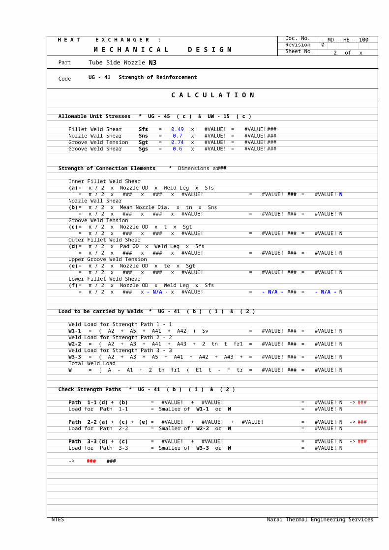
Part Tube Side Nozzle > N3
Code UG - 41 Strength of Reinforcement
C A L C U L A T I O N
Allowable Unit Stresses * UG - 45 ( c ) & UW - 15 ( c )
Fillet Weld Shear Sfs = 0.49 x #VALUE! = #VALUE! ###Nozzle Wall Shear Sns = 0.7 x #VALUE! = #VALUE! ###Groove Weld Tension Sgt = 0.74 x #VALUE! = #VALUE! ###Groove Weld Shear Sgs = 0.6 x #VALUE! = #VALUE! ###
Strength of Connection Elements * Dimensions are in ###
Inner Fillet Weld Shear(a) = π / 2 x Nozzle OD x Weld Leg x Sfs
= π / 2 x ### x ### x #VALUE! = #VALUE! ### = #VALUE! NNozzle Wall Shear(b) = π / 2 x Mean Nozzle Dia. x tn x Sns
= π / 2 x ### x ### x #VALUE! = #VALUE! ### = #VALUE! NGroove Weld Tension(c) = π / 2 x Nozzle OD x t x Sgt
= π / 2 x ### x ### x #VALUE! = #VALUE! ### = #VALUE! NOuter Fillet Weld Shear(d) = π / 2 x Pad OD x Weld Leg x Sfs
= π / 2 x ### x ### x #VALUE! = #VALUE! ### = #VALUE! NUpper Groove Weld Tension(e) = π / 2 x Nozzle OD x te x Sgt
= π / 2 x ### x ### x #VALUE! = #VALUE! ### = #VALUE! NLower Fillet Weld Shear(f) = π / 2 x Nozzle OD x Weld Leg x Sfs
= π / 2 x ### x - N/A - x #VALUE! = - N/A - ### = - N/A - N
Load to be carried by Welds * UG - 41 ( b ) ( 1 ) & ( 2 )
Weld Load for Strength Path 1 - 1W1-1 = ( A2 + A5 + A41 + A42 ) Sv = #VALUE! ### = #VALUE! NWeld Load for Strength Path 2 - 2W2-2 = ( A2 + A3 + A41 + A43 + 2 tn t fr1 ) Sv = #VALUE! ### = #VALUE! NWeld Load for Strength Path 3 - 3W3-3 = ( A2 + A3 + A5 + A41 + A42 + A43 + 2 tn t fr1 ) Sv = #VALUE! ### = #VALUE! NTotal Weld LoadW = [ A - A1 + 2 tn fr1 ( E1 t - F tr ) ] Sv = #VALUE! ### = #VALUE! N
Check Strength Paths * UG - 41 ( b ) ( 1 ) & ( 2 )
Path 1-1 (d) + (b) = #VALUE! + #VALUE! = #VALUE! N -> ###Load for Path 1-1 = = #VALUE! N
Path 2-2 (a) + (c) + (e) = #VALUE! + #VALUE! + #VALUE! = #VALUE! N -> ###Load for Path 2-2 = = #VALUE! N
Path 3-3 (d) + (c) = #VALUE! + #VALUE! = #VALUE! N -> ###Load for Path 3-3 = = #VALUE! N
-> ### ###
NTES Narai Thermal Engineering Services
Smaller of W1-1 or W
Smaller of W2-2 or W
Smaller of W3-3 or W

MD - HE - 100
N3
D E S I G N D A T A
STPG 370 E / 150 A / Sch.80
C A L C U L A T I O N
Narai Thermal Engineering Services

MD - HE - 100
N3
D E S I G N D A T A
C A L C U L A T I O N
Narai Thermal Engineering Services
te
For nozzle wall abutting
the vessel wall

MD - HE - 100
N3
C A L C U L A T I O N
Narai Thermal Engineering Services