mechanical/electrical addendum #: me-1
TRANSCRIPT

Page 1 of 4
Mechanical/Electrical Addendum #: ME-1
RE: Mozingo Conference Center Date: 10/5/2016
Maryville, Missouri BEC#: 1621To: Tom Wertzberger @ Wertzberger Architects, PC From: Brian K. Brewer, PE
This addendum forms a part of the contract documents and modifies the bidding documents dated09/07/2016, with amendments and additions noted below.
Acknowledge receipt of this addendum in the space provided in the bid form. Failure to do so maydisqualify the bidder.
This addendum consists of 4 pages + 8 schedules + 9 sheets + 19 pages specs.
PART 1 - CLARIFICATIONS
1.1 GEOTHERMAL HVAC ALTERNATE – The geothermal alternate includes a revised specificationfor the ground-mounted RTU; deleting furnace and condensing units and replacing withground source heat pumps; adding primary loop pumps; adding an interior buildinggeoloop, and designing an 85 ton geo-exchanger with 7-8 zone loop pumps and an interiorpiping loop to all units. Schedules are included in this addendum for revised HVACequipment. All units shall have source-water two-position two-way valves and primary looppumps shall be pressure-controlled variable speed driven. Zone loop pumps shall bevertical inline, constant speed. Mechanical/Controls contractor shall provide VFD’s and unitcontrol valves. EC shall include in their proposal the revised power connections and the newequipment connections (pumps, GSHP, and RTU) per the new schedules. Geo-exchangerconfiguration could be vertical or horizontal wells or horizontal loops.
1.2 INTERIOR AHU’s – All interior furnaces or air handling units are intended to be horizontalunits.
1.3 ALUMINUM CONDUCTORS – In lieu of specified copper, aluminum conductors properly sizedand installed per NEC are allowable for service entrance feeders only.
1.4 LOW VOLTAGE CABLES – Low voltage cables shall be installed in wire cable tray or wirehooks appropriately sized for the intended cable fill. “Free-flying” cable or wire/cable ties toother elements is not permitted.
1.5 ELECTRICAL SERVICE ENTRANCE – Service entrance feeders shall enter the building belowgrade in the Storage 122 and be routed directly into the MDP from overhead in conduit orgutter/wireway. Service feeder conduits shall be sealed to prevent condensation and waterentry from underground.
1.6 ELECTRICAL SURGE PROTECTION – Provide surge protectors on MDP and all 120-208subpanels per specifications, not required on LDP.
1.7 VOICE/DATA ENTRANCES – Provide (3) 3” conduits into Electrical 121 to backboard notedon plans. Extend conduits to accessible location 5’ beyond building wall and cap/stack forconnection by others.

Addendum #ME-1 Mozingo Conference Center, Maryville, MO10/05/2016 BEC#1621Page 2 of 4
PART 2 - CHANGES TO THE PROJECT SPECIFICATIONS
2.1 SECTION 23-2113 HYDRONIC PIPING
A. ADD this section for the geo-thermal alternate.
2.2 SECTION 23-2113.33 GROUND-LOOP HEAT-PUMP PIPING
A. ADD this section for the geo-thermal alternate.
2.3 SECTION 23-2114 HYDRONIC SPECIALTIES
A. ADD this section for the geo-thermal alternate.
2.4 SECTION 23-2123 HYDRONIC PUMPS
A. ADD this section for the geo-thermal alternate.
2.5 SECTION 28-3100 FIRE DETECTION AND ALARM
A. DELETE references and requirements for voice evacuation and multiple smoke zones.
PART 3 - CHANGES TO THE DRAWINGS
3.1 SHEET P1.1 – LOWER LEVEL PLUMBING PLAN
A. REPLACE P1.1 with attached sheet dated 10/4/2016.
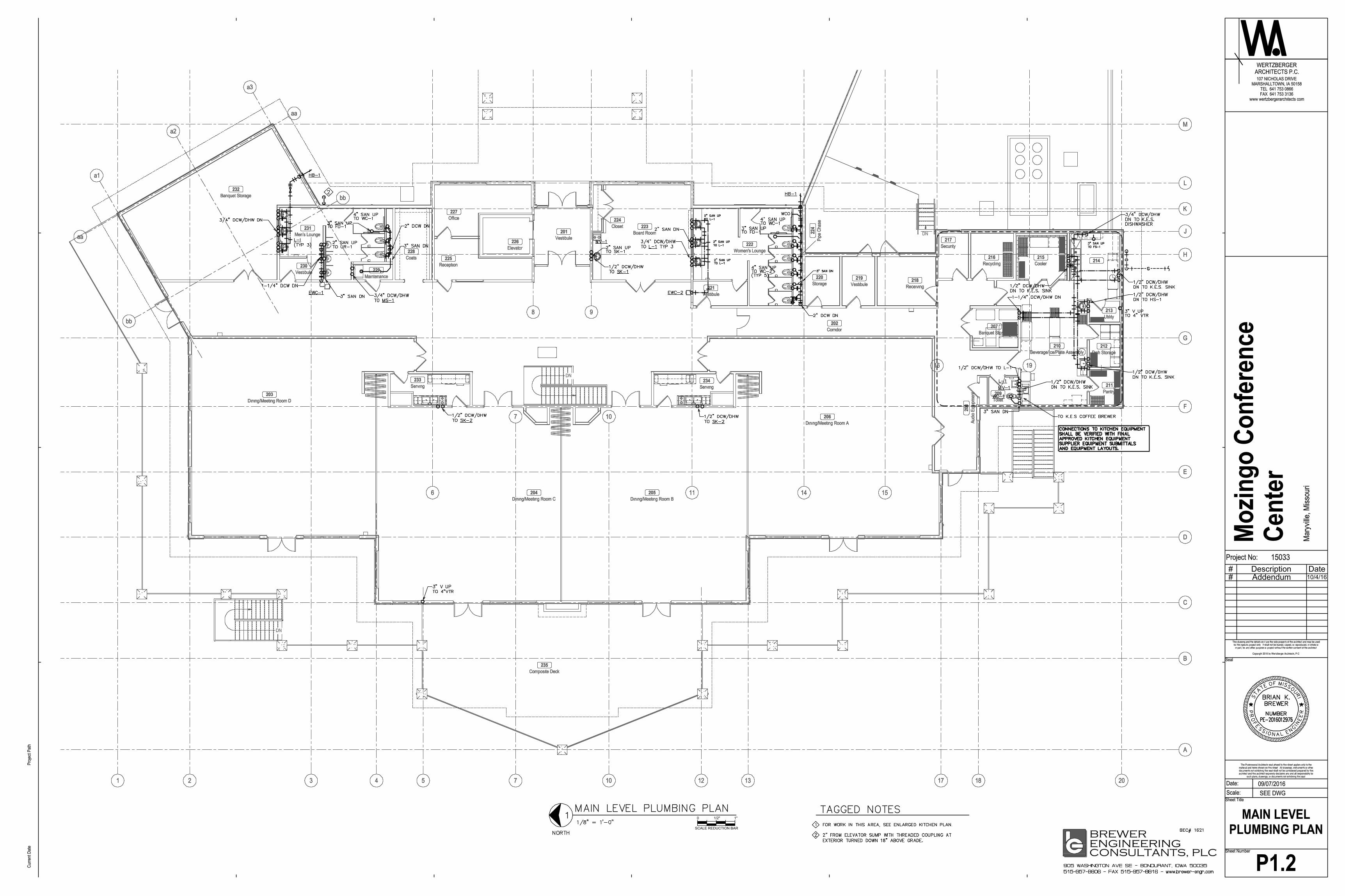
3.2 SHEET P1.2 – MAIN LEVEL PLUMBING PLAN
A. Replace P1.2 with attached sheet dated 10/4/2016.
3.3 SHEET P2.0 – PLUMBING DETAILS
A. Detail 9 – Grease Interceptor Detail:
1. DELETE “FUTURE” text. Interceptor is part of this project scope.
3.4 SHEET P3.0 – PLUMBING SCHEDULES
A. REPLACE plumbing piping schedule with attached sheet dated 10/4/2016.
B. ADD Advance Tabco hand sink (tag HS-1). Wall-mount, 14”Wx10”LX5”D bowl, 20 gauge304 series stainless steel, with deck mounted fixed faucet, and basket drain.
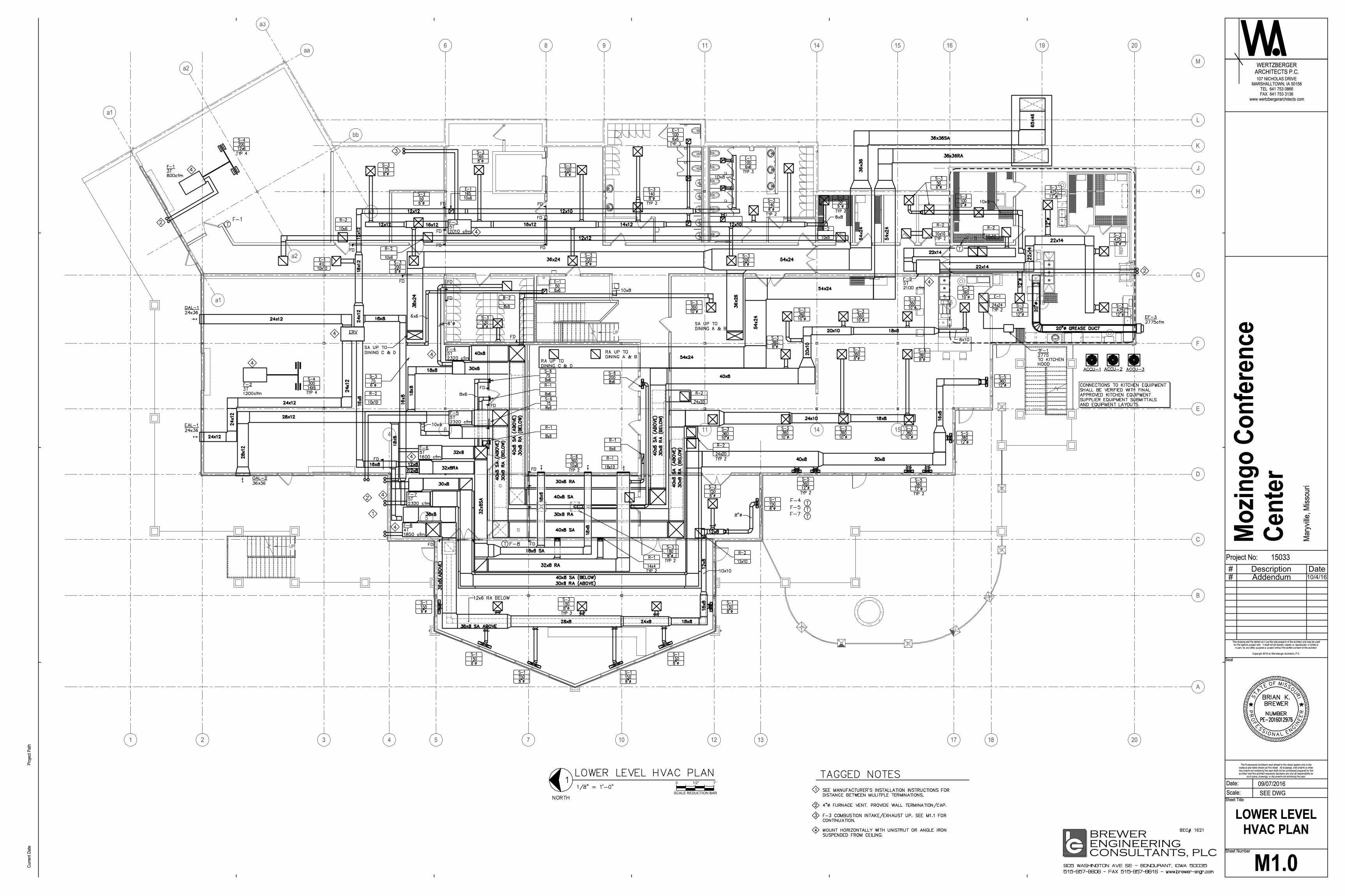
3.5 SHEET M1.0 – LOWER LEVEL HVAC PLAN
A. REPLACE this sheet with attached sheet M1.0 dated 10/4/2016.
3.6 SHEET M1.1 – UPPER LEVEL HVAC PLAN
A. REPLACE this sheet with attached sheet M1.1 dated 10/4/2016.
3.7 SHEET M2.0 – MECHANICAL DETAILS
A. REPLACE this sheet with attached sheet M2.0 dated 10/4/2016.

Addendum #ME-1 Mozingo Conference Center, Maryville, MO10/05/2016 BEC#1621Page 3 of 4
3.8 SHEET M3.0 – MECHANICAL SCHEDULES
A. REPLACE “RTU 1-4” mark with “RTU-1”.
B. REPLACE furnace and condensing unit schedule with attached sheet dated 10/4/2016.
C. REPLACE VAV-9 on VAV Box Schedule with attached sheet dated 10/4/2016.
D. ADD Rooftop Unit Schedule (Alternate – Geo) with attached sheet dated 10/4/2016.
E. ADD Ground Source Heat Pump Schedule (Alternate – Geo) with attached sheet dated10/4/2016.
F. ADD Pump Schedule (Alternate – Geo) with attached sheet dated 10/4/2016.
3.9 SHEET M3.1 – MECHANICAL SCHEDULES
A. REPLACE “24X48” size for R-1 with “INLET +1-1/4”
B. REPLACE duct schedule with attached sheet dated 10/4/2016.
3.10 SHEET E1.0 – LOWER LEVEL POWER PLAN
A. REPLACE this sheet with E1.0 dated 10/5/2016.
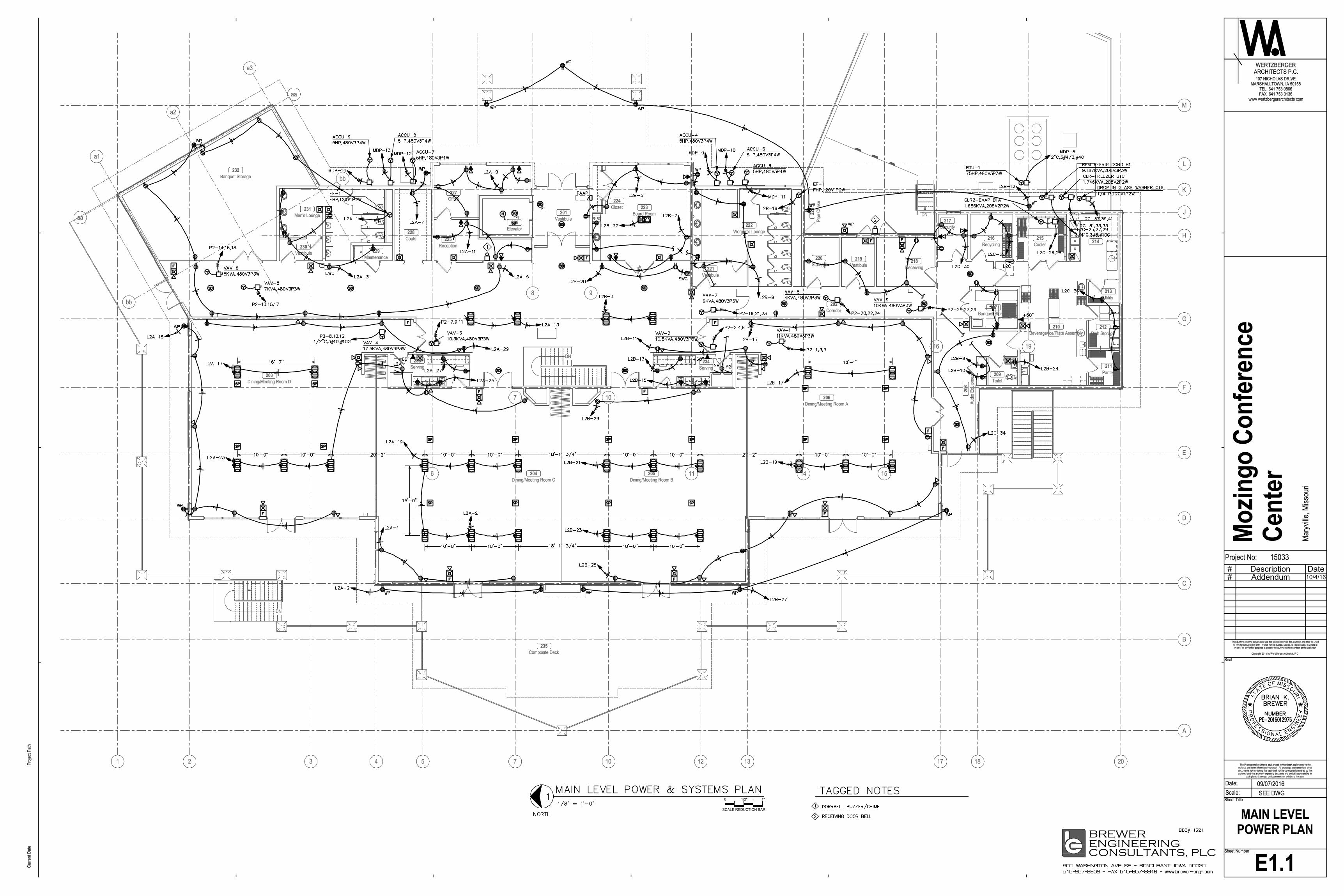
3.11 SHEET E1.1 – UPPER LEVEL POWER PLAN
A. REPLACE this sheet with E1.1 dated 10/5/2016.
3.12 SHEET E2.0 – LOWER LEVEL LIGHTING PLAN
A. NOTE light switches are shown generically and will need to be configured as 3-way and4-way as relevant to the number of switches shown.
3.13 SHEET E2.1 – MAIN LEVEL LIGHTING PLAN
A. NOTE exit signs in rooms 218 and 219 are type “EX1”.
B. NOTE light switches are shown generically and will need to be configured as 3-way and4-way as relevant to the number of switches shown.
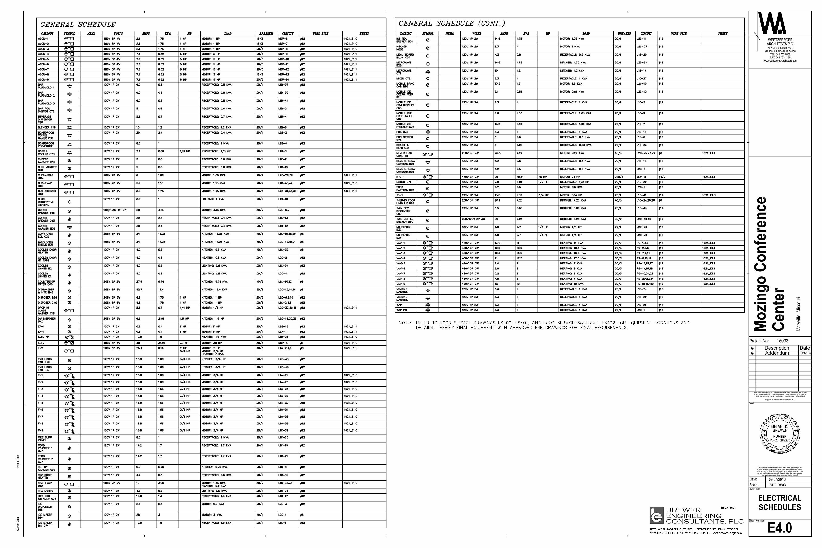
3.14 SHEET E4.0 – ELECTRICAL SCHEDULES
A. REPLACE this sheet with attached sheet E4.0 dated 10/05/2016.
3.15 SHEET E4.1 – ELECTRICAL SCHEDULES
A. REPLACE this sheet with attached sheet E4.1 dated 10/05/2016.
B. ADD note to all 208/120V subpanels “ALL NOTED SPACES FILLED WITH 20A/1P SPAREBREAKERS FOR FUTURE.”

Addendum #ME-1 Mozingo Conference Center, Maryville, MO10/05/2016 BEC#1621Page 4 of 4
PART 4 - PRODUCT APPROVALS
The following manufacturers are approved for bidding on this project. The products andmanufacturers listed are required to meet the project documents regardless of this approval.Conformance with the project documents will be evaluated during the submittal phase:
Specification Section Product Manufacturer238127 Gas-fired furnaces Carrier233600 Air Terminal Units Titus230923 HVAC Controls ASI Controls
Sincerely,Brewer Engineering Consultants, PLC
P:\2016\1621.MozingoConfCenter\CD\Addenda\1621_MEP-Addendum_No_1.docx
END of ADDENDUM #ME-1
BEC# 1621 / Mozingo Conference Center 23 2113 - 1 HYDRONIC PIPINGFor Bidding
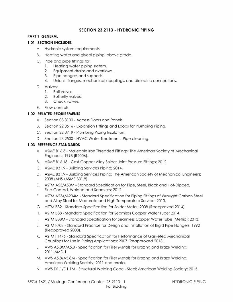
SECTION 23 2113 - HYDRONIC PIPINGPART 1 GENERAL1.01 SECTION INCLUDES
A. Hydronic system requirements.B. Heating water and glycol piping, above grade.C. Pipe and pipe fittings for:
1. Heating water piping system.2. Equipment drains and overflows.3. Pipe hangers and supports.4. Unions, flanges, mechanical couplings, and dielectric connections.
D. Valves:1. Ball valves.2. Butterfly valves.3. Check valves.
E. Flow controls.1.02 RELATED REQUIREMENTS
A. Section 08 3100 - Access Doors and Panels.B. Section 22 0516 - Expansion Fittings and Loops for Plumbing Piping.C. Section 22 0719 - Plumbing Piping Insulation.D. Section 23 2500 - HVAC Water Treatment: Pipe cleaning.
1.03 REFERENCE STANDARDSA. ASME B16.3 - Malleable Iron Threaded Fittings; The American Society of Mechanical
Engineers; 1998 (R2006).B. ASME B16.18 - Cast Copper Alloy Solder Joint Pressure Fittings; 2012.C. ASME B31.9 - Building Services Piping; 2014.D. ASME B31.9 - Building Services Piping; The American Society of Mechanical Engineers;
2008 (ANSI/ASME B31.9).E. ASTM A53/A53M - Standard Specification for Pipe, Steel, Black and Hot-Dipped,
Zinc-Coated, Welded and Seamless; 2012.F. ASTM A234/A234M - Standard Specification for Piping Fittings of Wrought Carbon Steel
and Alloy Steel for Moderate and High Temperature Service; 2013.G. ASTM B32 - Standard Specification for Solder Metal; 2008 (Reapproved 2014).H. ASTM B88 - Standard Specification for Seamless Copper Water Tube; 2014.I. ASTM B88M - Standard Specification for Seamless Copper Water Tube (Metric); 2013.J. ASTM F708 - Standard Practice for Design and Installation of Rigid Pipe Hangers; 1992
(Reapproved 2008).K. ASTM F1476 - Standard Specification for Performance of Gasketed Mechanical
Couplings for Use in Piping Applications; 2007 (Reapproved 2013).L. AWS A5.8M/A5.8 - Specification for Filler Metals for Brazing and Braze Welding;
2011-AMD 1.M. AWS A5.8/A5.8M - Specification for Filler Metals for Brazing and Braze Welding;
American Welding Society; 2011 and errata.N. AWS D1.1/D1.1M - Structural Welding Code - Steel; American Welding Society; 2015.
BEC# 1621 / Mozingo Conference Center 23 2113 - 2 HYDRONIC PIPINGFor Bidding
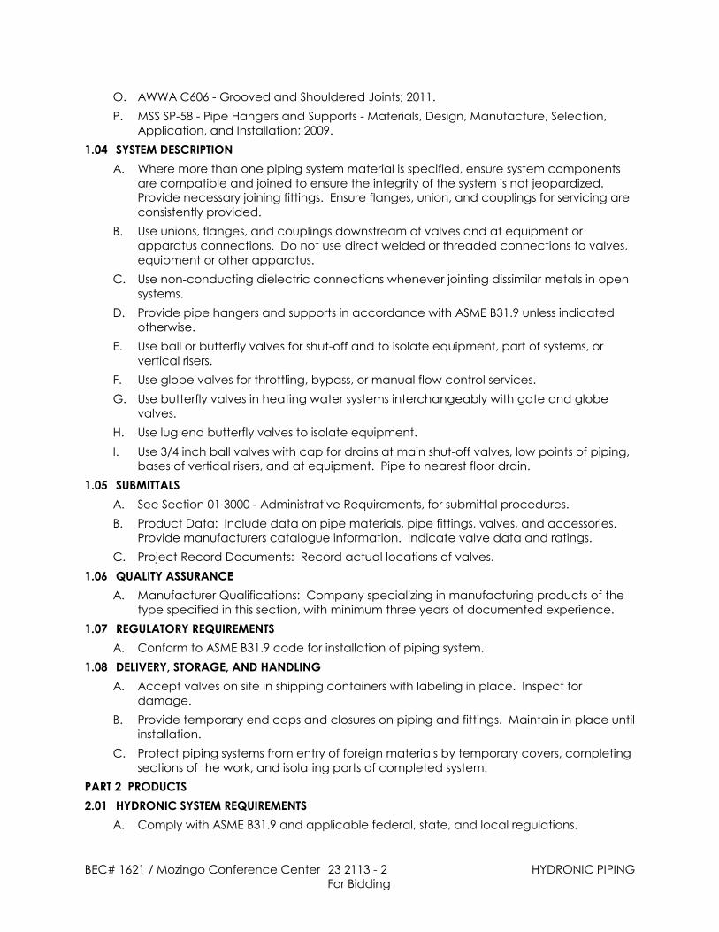
O. AWWA C606 - Grooved and Shouldered Joints; 2011.P. MSS SP-58 - Pipe Hangers and Supports - Materials, Design, Manufacture, Selection,
Application, and Installation; 2009.1.04 SYSTEM DESCRIPTION
A. Where more than one piping system material is specified, ensure system componentsare compatible and joined to ensure the integrity of the system is not jeopardized. Provide necessary joining fittings. Ensure flanges, union, and couplings for servicing areconsistently provided.
B. Use unions, flanges, and couplings downstream of valves and at equipment orapparatus connections. Do not use direct welded or threaded connections to valves,equipment or other apparatus.
C. Use non-conducting dielectric connections whenever jointing dissimilar metals in opensystems.
D. Provide pipe hangers and supports in accordance with ASME B31.9 unless indicatedotherwise.
E. Use ball or butterfly valves for shut-off and to isolate equipment, part of systems, orvertical risers.
F. Use globe valves for throttling, bypass, or manual flow control services.G. Use butterfly valves in heating water systems interchangeably with gate and globe
valves.H. Use lug end butterfly valves to isolate equipment.I. Use 3/4 inch ball valves with cap for drains at main shut-off valves, low points of piping,
bases of vertical risers, and at equipment. Pipe to nearest floor drain.1.05 SUBMITTALS
A. See Section 01 3000 - Administrative Requirements, for submittal procedures.B. Product Data: Include data on pipe materials, pipe fittings, valves, and accessories.
Provide manufacturers catalogue information. Indicate valve data and ratings.C. Project Record Documents: Record actual locations of valves.
1.06 QUALITY ASSURANCEA. Manufacturer Qualifications: Company specializing in manufacturing products of the
type specified in this section, with minimum three years of documented experience.1.07 REGULATORY REQUIREMENTS
A. Conform to ASME B31.9 code for installation of piping system.1.08 DELIVERY, STORAGE, AND HANDLING
A. Accept valves on site in shipping containers with labeling in place. Inspect fordamage.
B. Provide temporary end caps and closures on piping and fittings. Maintain in place untilinstallation.
C. Protect piping systems from entry of foreign materials by temporary covers, completingsections of the work, and isolating parts of completed system.
PART 2 PRODUCTS2.01 HYDRONIC SYSTEM REQUIREMENTS
A. Comply with ASME B31.9 and applicable federal, state, and local regulations.

BEC# 1621 / Mozingo Conference Center 23 2113 - 3 HYDRONIC PIPINGFor Bidding
B. Piping: Provide piping, fittings, hangers and supports as required, as indicated, and asfollows:1. Where more than one piping system material is specified, provide joining fittings
that are compatible with piping materials and ensure that the integrity of thesystem is not jeopardized.
2. Use non-conducting dielectric connections whenever jointing dissimilar metals.3. Grooved mechanical joints may be used in accessible locations only.
a. Accessible locations include those exposed on interior of building, in pipechases, and in mechanical rooms, aboveground outdoors, and as approvedby Architect/Engineer.
b. Use rigid joints unless otherwise indicated.4. Provide pipe hangers and supports in accordance with ASME B31.9 or MSS SP-58
unless indicated otherwise.5. Provide pipe hangers and supports in accordance with ASME B31.9 unless
indicated otherwise.C. Pipe-to-Valve and Pipe-to-Equipment Connections: Use flanges, unions, or grooved
couplings to allow disconnection of components for servicing; do not use directwelded, soldered, or threaded connections.
D. Valves: Provide valves where indicated:2.02 HEATING WATER AND GLYCOL PIPING, ABOVE GRADE
A. Steel Pipe: ASTM A53/A53M, Schedule 40, black, using one of the following joint types:1. Welded Joints: ASTM A234/A234M, wrought steel welding type fittings; AWS
D1.1/D1.1M welded.2. Fittings: ASTM B 16.3, malleable iron or ASTM A 234/A 234M, wrought steel welding
type fittings.3. Joints: Threaded, AWS D1.1 welded, or grooved and shouldered pipe end
couplings.B. Copper Tube: ASTM B88 (ASTM B88M), Type L (B), drawn, using one of the following joint
types:C.
1. Solder Joints: ASME B16.18 cast brass/bronze or ASME B16.22 solder wroughtcopper fittings.a. Solder: ASTM B32 lead-free solder, HB alloy (95-5 tin-antimony) or tin and silver.b. Braze: AWS A5.8M/A5.8 BCuP copper/silver alloy.c. Braze: 1 BCuP copper/silver alloy.
2. Tee Connections: Mechanically extracted collars with notched and dimpledbranch tube.
3. Joints: Solder, lead free, 95-5 tin-antimony, or tin and silver.2.03 EQUIPMENT DRAINS AND OVERFLOWS
A. Copper Tube: ASTM B88 (ASTM B88M), Type K (A), drawn; using one of the followingjoint types:1. Joints: Solder, lead free, ASTM B 32, HB alloy (95-5 tin-antimony), or tin and silver.
2.04 PIPE HANGERS AND SUPPORTSA. Provide hangers and supports that comply with MSS SP-58.
1. If type of hanger or support for a particular situation is not indicated, selectappropriate type using MSS SP-58 recommendations.
B. Conform to ASME B31.9.
BEC# 1621 / Mozingo Conference Center 23 2113 - 4 HYDRONIC PIPING For Bidding
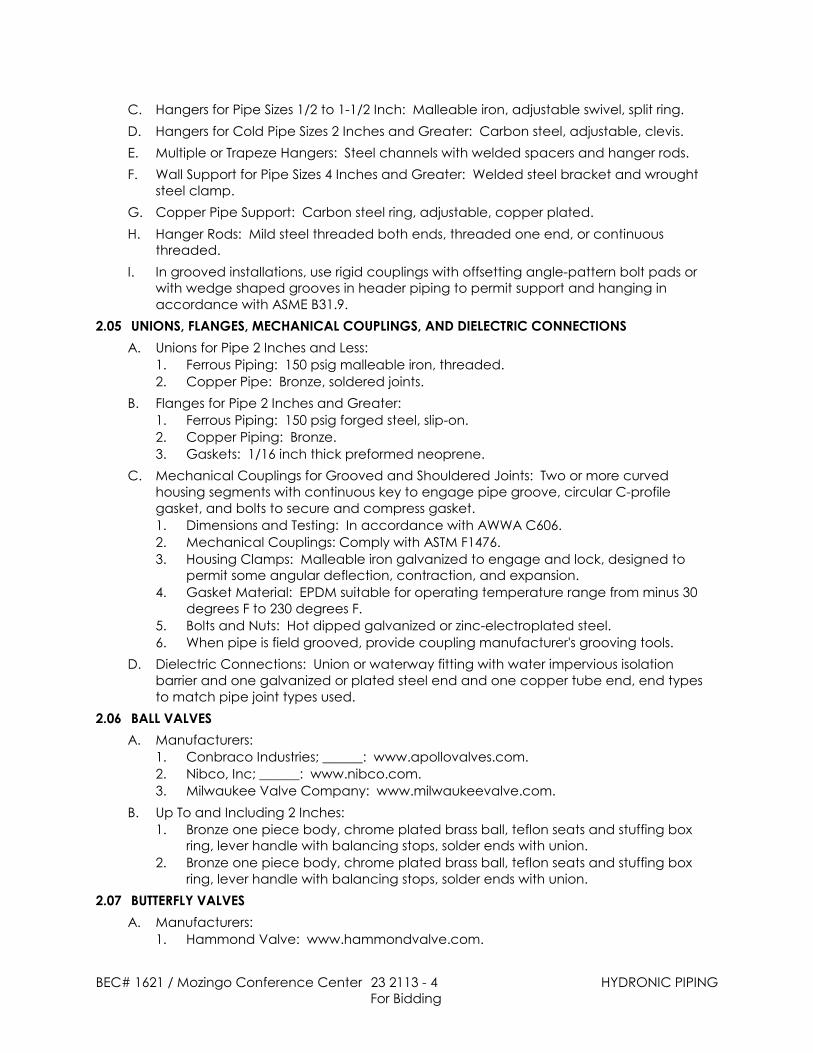
C. Hangers for Pipe Sizes 1/2 to 1-1/2 Inch: Malleable iron, adjustable swivel, split ring.D. Hangers for Cold Pipe Sizes 2 Inches and Greater: Carbon steel, adjustable, clevis.E. Multiple or Trapeze Hangers: Steel channels with welded spacers and hanger rods.F. Wall Support for Pipe Sizes 4 Inches and Greater: Welded steel bracket and wrought
steel clamp.G. Copper Pipe Support: Carbon steel ring, adjustable, copper plated.H. Hanger Rods: Mild steel threaded both ends, threaded one end, or continuous
threaded.I. In grooved installations, use rigid couplings with offsetting angle-pattern bolt pads or
with wedge shaped grooves in header piping to permit support and hanging inaccordance with ASME B31.9.
2.05 UNIONS, FLANGES, MECHANICAL COUPLINGS, AND DIELECTRIC CONNECTIONSA. Unions for Pipe 2 Inches and Less:
1. Ferrous Piping: 150 psig malleable iron, threaded.2. Copper Pipe: Bronze, soldered joints.
B. Flanges for Pipe 2 Inches and Greater:1. Ferrous Piping: 150 psig forged steel, slip-on.2. Copper Piping: Bronze.3. Gaskets: 1/16 inch thick preformed neoprene.
C. Mechanical Couplings for Grooved and Shouldered Joints: Two or more curvedhousing segments with continuous key to engage pipe groove, circular C-profilegasket, and bolts to secure and compress gasket.1. Dimensions and Testing: In accordance with AWWA C606.2. Mechanical Couplings: Comply with ASTM F1476.3. Housing Clamps: Malleable iron galvanized to engage and lock, designed to
permit some angular deflection, contraction, and expansion.4. Gasket Material: EPDM suitable for operating temperature range from minus 30
degrees F to 230 degrees F.5. Bolts and Nuts: Hot dipped galvanized or zinc-electroplated steel.6. When pipe is field grooved, provide coupling manufacturer's grooving tools.
D. Dielectric Connections: Union or waterway fitting with water impervious isolationbarrier and one galvanized or plated steel end and one copper tube end, end typesto match pipe joint types used.
2.06 BALL VALVESA. Manufacturers:
1. Conbraco Industries; ______: www.apollovalves.com.2. Nibco, Inc; ______: www.nibco.com.3. Milwaukee Valve Company: www.milwaukeevalve.com.
B. Up To and Including 2 Inches:1. Bronze one piece body, chrome plated brass ball, teflon seats and stuffing box
ring, lever handle with balancing stops, solder ends with union.2. Bronze one piece body, chrome plated brass ball, teflon seats and stuffing box
ring, lever handle with balancing stops, solder ends with union.2.07 BUTTERFLY VALVES
A. Manufacturers:1. Hammond Valve: www.hammondvalve.com.

BEC# 1621 / Mozingo Conference Center 23 2113 - 5 HYDRONIC PIPING For Bidding
2. Crane Co.; ______: www.craneco.com.3. Milwaukee Valve Company; ______: www.milwaukeevalve.com.
B. Body: Cast or ductile iron with resilient replaceable EPDM seat, wafer, lug, grooved, or______ ends, extended neck.
C. Disc: Construct of aluminum bronze, chrome plated ductile iron, stainless steel, ductileiron with EPDM encapsulation, Buna-N encapsulation, or _________________.
D. Body: Cast or ductile iron with resilient replaceable EPDM seat, wafer or lug ends,extended neck.
E. Disc: Aluminum bronze.F. Operator: 10 position lever handle.
2.08 SWING CHECK VALVESA. Manufacturers:
1. Crane Valve2. Hammond Valve; ______: www.hammondvalve.com.3. Nibco, Inc; ______: www.nibco.com.4. Milwaukee Valve Company: www.milwaukeevalve.com.
B. Up To and Including 2 Inches:1. Bronze body, bronze trim, bronze rotating swing disc, with composition disc, solder
ends.C. Over 2 Inches:
1. Iron body, bronze or ________ trim, stainless steel, bronze, bronze faced rotating, or_____________ swing disc, renewable disc and seat, flanged, grooved, or__________ ends.
2. Iron body, bronze trim, bronze or bronze faced rotating swing disc, renewable discand seat, flanged ends.
2.09 SPRING LOADED CHECK VALVESA. Manufacturers:
1. Hammond Valve; ______: www.hammondvalve.com.2. Crane Co.: www.cranevalve.com.3. Milwaukee Valve Company; ______: www.milwaukeevalve.com.
B. Iron body, bronze trim, split plate, hinged with stainless steel spring, resilient seal bondedto body, wafer or threaded lug ends.
2.10 FLOW CONTROLSA. Manufacturers:
1. ITT Bell & Gossett; ______: www.bellgossett.com.2. Griswold Controls: www.griswoldcontrols.com.3. Taco, Inc; ______: www.taco-hvac.com.
B. Construction: Class 125, Brass or bronze body with union on inlet and outlet,temperature and pressure test plug on inlet and outlet, blowdown/backflush drain.
C. Calibration: Control flow within 5 percent of selected rating, over operating pressurerange of 10 times minimum pressure required for control, maximum minimum pressure3.5 psi.
PART 3 EXECUTION3.01 PREPARATION
A. Ream pipe and tube ends. Remove burrs. Bevel plain end ferrous pipe.
BEC# 1621 / Mozingo Conference Center 23 2113 - 6 HYDRONIC PIPING For Bidding
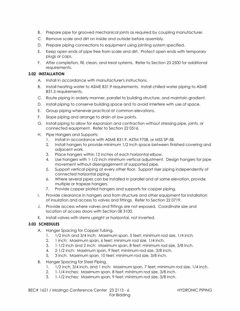
B. Prepare pipe for grooved mechanical joints as required by coupling manufacturer.C. Remove scale and dirt on inside and outside before assembly.D. Prepare piping connections to equipment using jointing system specified.E. Keep open ends of pipe free from scale and dirt. Protect open ends with temporary
plugs or caps.F. After completion, fill, clean, and treat systems. Refer to Section 23 2500 for additional
requirements.3.02 INSTALLATION
A. Install in accordance with manufacturer's instructions.B. Install heating water to ASME B31.9 requirements. Install chilled water piping to ASME
B31.5 requirements.C. Route piping in orderly manner, parallel to building structure, and maintain gradient.D. Install piping to conserve building space and to avoid interfere with use of space.E. Group piping whenever practical at common elevations.F. Slope piping and arrange to drain at low points.G. Install piping to allow for expansion and contraction without stressing pipe, joints, or
connected equipment. Refer to Section 22 0516.H. Pipe Hangers and Supports:
1. Install in accordance with ASME B31.9, ASTM F708, or MSS SP-58.2. Install hangers to provide minimum 1/2 inch space between finished covering and
adjacent work.3. Place hangers within 12 inches of each horizontal elbow.4. Use hangers with 1-1/2 inch minimum vertical adjustment. Design hangers for pipe
movement without disengagement of supported pipe.5. Support vertical piping at every other floor. Support riser piping independently of
connected horizontal piping.6. Where several pipes can be installed in parallel and at same elevation, provide
multiple or trapeze hangers.7. Provide copper plated hangers and supports for copper piping.
I. Provide clearance in hangers and from structure and other equipment for installationof insulation and access to valves and fittings. Refer to Section 22 0719.
J. Provide access where valves and fittings are not exposed. Coordinate size andlocation of access doors with Section 08 3100.
K. Install valves with stems upright or horizontal, not inverted.3.03 SCHEDULES
A. Hanger Spacing for Copper Tubing.1. 1/2 inch and 3/4 inch: Maximum span, 5 feet; minimum rod size, 1/4 inch.2. 1 inch: Maximum span, 6 feet; minimum rod size, 1/4 inch.3. 1-1/2 inch and 2 inch: Maximum span, 8 feet; minimum rod size, 3/8 inch.4. 2-1/2 inch: Maximum span, 9 feet; minimum rod size, 3/8 inch.5. 3 inch: Maximum span, 10 feet; minimum rod size, 3/8 inch.
B. Hanger Spacing for Steel Piping.1. 1/2 inch, 3/4 inch, and 1 inch: Maximum span, 7 feet; minimum rod size, 1/4 inch.2. 1-1/4 inches: Maximum span, 8 feet; minimum rod size, 3/8 inch.3. 1-1/2 inches: Maximum span, 9 feet; minimum rod size, 3/8 inch.

BEC# 1621 / Mozingo Conference Center 23 2113 - 7 HYDRONIC PIPING For Bidding
4. 2 inches: Maximum span, 10 feet; minimum rod size, 3/8 inch.5. 2-1/2 inches: Maximum span, 11 feet; minimum rod size, 3/8 inch.6. 3 inches: Maximum span, 12 feet; minimum rod size, 3/8 inch.
END OF SECTION
BEC# 1621 / Mozingo Conference Center 23 2113.33 - 1 GROUND-LOOP HEAT-PUMP PIPINGFor Bidding
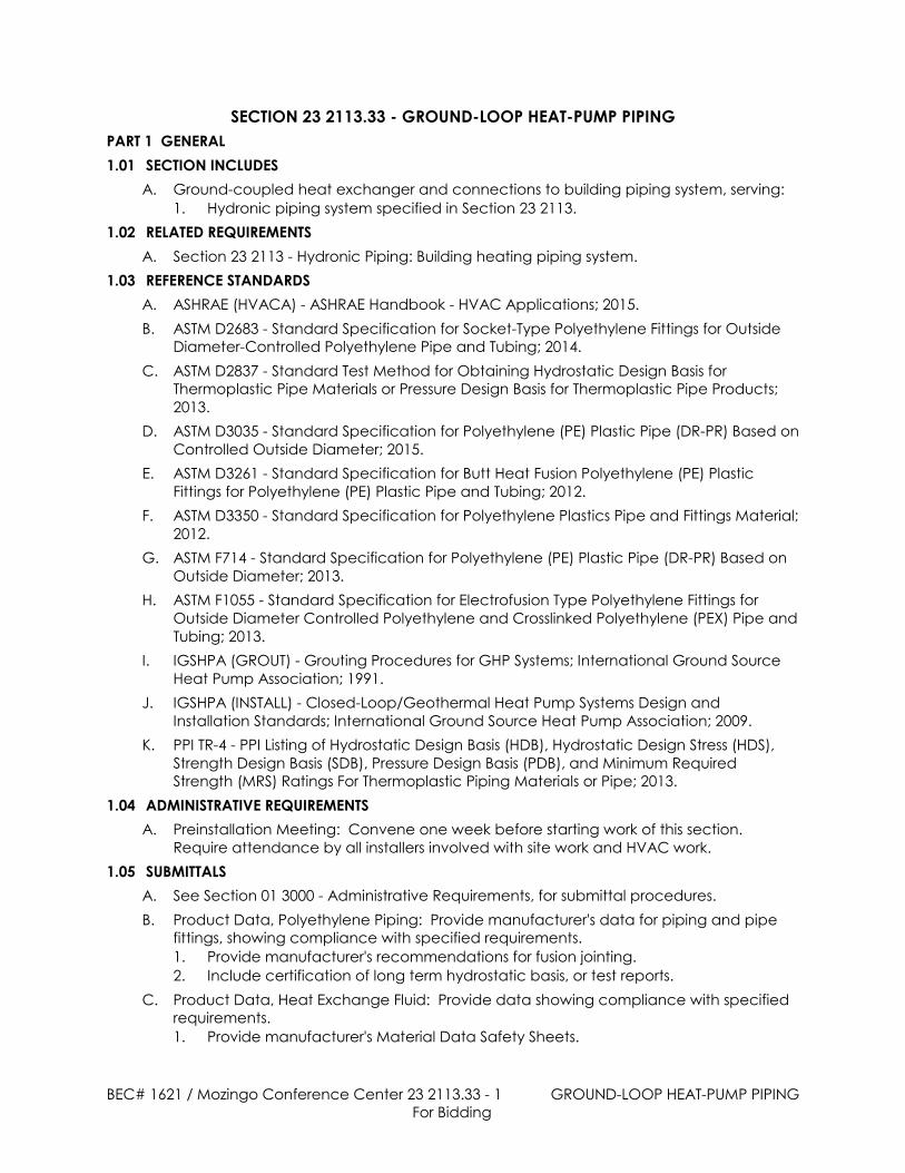
SECTION 23 2113.33 - GROUND-LOOP HEAT-PUMP PIPINGPART 1 GENERAL1.01 SECTION INCLUDES
A. Ground-coupled heat exchanger and connections to building piping system, serving:1. Hydronic piping system specified in Section 23 2113.
1.02 RELATED REQUIREMENTSA. Section 23 2113 - Hydronic Piping: Building heating piping system.
1.03 REFERENCE STANDARDSA. ASHRAE (HVACA) - ASHRAE Handbook - HVAC Applications; 2015.B. ASTM D2683 - Standard Specification for Socket-Type Polyethylene Fittings for Outside
Diameter-Controlled Polyethylene Pipe and Tubing; 2014.C. ASTM D2837 - Standard Test Method for Obtaining Hydrostatic Design Basis for
Thermoplastic Pipe Materials or Pressure Design Basis for Thermoplastic Pipe Products;2013.
D. ASTM D3035 - Standard Specification for Polyethylene (PE) Plastic Pipe (DR-PR) Based onControlled Outside Diameter; 2015.
E. ASTM D3261 - Standard Specification for Butt Heat Fusion Polyethylene (PE) PlasticFittings for Polyethylene (PE) Plastic Pipe and Tubing; 2012.
F. ASTM D3350 - Standard Specification for Polyethylene Plastics Pipe and Fittings Material;2012.
G. ASTM F714 - Standard Specification for Polyethylene (PE) Plastic Pipe (DR-PR) Based onOutside Diameter; 2013.
H. ASTM F1055 - Standard Specification for Electrofusion Type Polyethylene Fittings forOutside Diameter Controlled Polyethylene and Crosslinked Polyethylene (PEX) Pipe andTubing; 2013.
I. IGSHPA (GROUT) - Grouting Procedures for GHP Systems; International Ground SourceHeat Pump Association; 1991.
J. IGSHPA (INSTALL) - Closed-Loop/Geothermal Heat Pump Systems Design andInstallation Standards; International Ground Source Heat Pump Association; 2009.
K. PPI TR-4 - PPI Listing of Hydrostatic Design Basis (HDB), Hydrostatic Design Stress (HDS),Strength Design Basis (SDB), Pressure Design Basis (PDB), and Minimum RequiredStrength (MRS) Ratings For Thermoplastic Piping Materials or Pipe; 2013.
1.04 ADMINISTRATIVE REQUIREMENTSA. Preinstallation Meeting: Convene one week before starting work of this section.
Require attendance by all installers involved with site work and HVAC work.1.05 SUBMITTALS
A. See Section 01 3000 - Administrative Requirements, for submittal procedures.B. Product Data, Polyethylene Piping: Provide manufacturer's data for piping and pipe
fittings, showing compliance with specified requirements.1. Provide manufacturer's recommendations for fusion jointing.2. Include certification of long term hydrostatic basis, or test reports.
C. Product Data, Heat Exchange Fluid: Provide data showing compliance with specifiedrequirements.1. Provide manufacturer's Material Data Safety Sheets.
BEC# 1621 / Mozingo Conference Center 23 2113.33 - 2 GROUND-LOOP HEAT-PUMP PIPINGFor Bidding
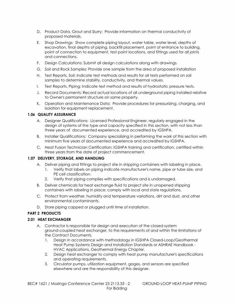
D. Product Data, Grout and Slurry: Provide information on thermal conductivity ofproposed materials.
E. Shop Drawings: Show complete piping layout, water table, water level, depths ofexcavation, final depths of piping, backfill placement, point of entrance to building,point of connection to equipment, test point locations, and fittings used for all jointsand connections.
F. Design Calculations: Submit all design calculations along with drawings.G. Soil and Rock Samples: Provide one sample from the area of proposed installationH. Test Reports, Soil: Indicate test methods and results for all tests performed on soil
samples to determine stability, conductivity, and thermal values.I. Test Reports, Piping: Indicate test method and results of hydrostatic pressure tests.J. Record Documents: Record actual locations of all underground piping installed relative
to Owner's permanent structure on same property.K. Operation and Maintenance Data: Provide procedures for pressurizing, charging, and
isolation for equipment replacement.1.06 QUALITY ASSURANCE
A. Designer Qualifications: Licensed Professional Engineer, regularly engaged in thedesign of systems of the type and capacity specified in this section, with not less thanthree years of documented experience, and accredited by IGSHPA.
B. Installer Qualifications: Company specializing in performing the work of this section withminimum five years of documented experience and accredited by IGSHPA.
C. Heat Fusion Technician Certification: IGSHPA training and certification, certified withinthree years from the date of project commencement.
1.07 DELIVERY, STORAGE, AND HANDLINGA. Deliver piping and fittings to project site in shipping containers with labeling in place.
1. Verify that labels on piping indicate manufacturer's name, pipe or tube size, andPE cell classification.
2. Verify that piping complies with specifications and is undamaged.B. Deliver chemicals for heat exchange fluid to project site in unopened shipping
containers with labeling in place; comply with local and state regulations.C. Protect from weather, humidity and temperature variations, dirt and dust, and other
environmental contaminants.D. Store piping capped or plugged until time of installation.
PART 2 PRODUCTS2.01 HEAT EXCHANGER
A. Contractor is responsible for design and execution of the closed-systemground-coupled heat exchanger, to the requirements of and within the limitations ofthe Contract Documents.1. Design in accordance with methodology in IGSHPA Closed-Loop/Geothermal
Heat Pump Systems Design and Installation Standards or ASHRAE Handbook -HVAC Applications, Geothermal Energy Chapter.
2. Design heat exchanger to comply with heat pump manufacturer's specificationsand operating requirements.
3. Circulator pumps, utilization equipment, gages, and sensors are specifiedelsewhere and are the responsibility of this designer.

BEC# 1621 / Mozingo Conference Center 23 2113.33 - 3 GROUND-LOOP HEAT-PUMP PIPINGFor Bidding
4. If the Drawings do not indicate the interface between the heat exchanger andthe equipment, provide three valves and a by-pass to isolate the heat exchangerfrom the equipment plus at least one charging valve.
B. Heat Exchanger Configuration: Closed system; polyethylene piping in verticalboreholes located adjacent to building, as indicated on drawings.1. Total Pipe Length: TBD feet.2. Pipe Diameter: TBD inch.3. Borehole Dimensions and Spacing: As required to achieve specified performance.4. Borehole Spacing: 20 feet, minimum.5. Total Number of Boreholes: 84.
C. Heat Exchanger Configuration: Closed system; horizontal polyethylene piping runningparallel, connected with U-bends, located in trenches.1. Total Pipe Length: TBD feet.2. Pipe Diameter: TBD inch.3. Depth: 4 feet.
D. Heat Exchanger Performance:1. Heat Transfer Capacity for Cooling: 1,020,000 Btuh.
2.02 MATERIALSA. Pipe: High density polyethylene pipe, type PE3408, PE3608, or PE4710, with minimum
ASTM D3350 cell classification of PE345364C.1. Pipe Used in Vertical Bore Applications: Comply with ASTM D3035 with minimum
working pressure rating of 160 psi.2. Other Pipe of 3 Inches Diameter and Larger: Comply with ASTM D3035 or ASTM
F714, with minimum working pressure rating of 100 psi.3. Other Pipe 1.25 Inches But Less Than 3 Inches In Diameter (Nominal): Comply with
ASTM D3035 with minimum working pressure rating of 110 psi.4. Other Pipe Less Than 1.25 Inches in Diameter (Nominal): Comply with ASTM D3035
with minimum working pressure rating of 160 psi.5. Long Term Hydrostatic Design Basis: 1600 psi at 73 degrees F, when tested in
accordance with ASTM D2837; appropriate listing in current edition of PPI TR-4 willconstitute evidence of compliance with this requirement; otherwise, submitindependent test results.
6. Joints and Fittings: Polyethylene of same type as pipe, of sizes and types suitablefor the pipe being used; use only heat fusion or stab-type mechanical fittings thatare quality controlled to provide a leak-free union between piping ends that isstronger than the piping itself. Do not use other barbed fittings or hose clamps.a. Electrofusion Type Fittings: Comply with ASTM F1055.b. Butt Fusion Fittings: Comply with ASTM D3261.c. Socket Type Fittings: Comply with ASTM D2683.d. Where threaded fittings must be used for connection to equipment or
dissimilar piping, use fittings and thread sealant compatible and effective withantifreeze used.
B. Heat Exchange Fluid: Water and antifreeze solution, 25 percent propylene glycol byweight.
C. Detectable Underground Tape: Magnetic detectable conductor in 2 inch widerot-resistant plastic tape or mesh, brightly colored, imprinted with "Water Line" in largeletters.
D. Backfill for Vertical Boreholes: Thermally enhanced bentonite.

BEC# 1621 / Mozingo Conference Center 23 2113.33 - 4 GROUND-LOOP HEAT-PUMP PIPINGFor Bidding
PART 3 EXECUTION3.01 EXAMINATION AND PREPARATION
A. Verify location of existing structures and utilities prior to excavation.B. Verify soil composition and rock depth, if any, before beginning excavation.C. Protect adjacent structures from the effects of excavation.D. Verify that layout dimensions are correct and that available land is sufficient for design.E. Notify Architect/Engineer of unsatisfactory conditions.F. Do not proceed with installation until unsatisfactory conditions have been corrected.G. Coordinate work with site grading, site backfilling, and foundation construction.
3.02 EXCAVATIONA. Excavate in accordance with requirements of authorities having jurisdiction.B. Remove rock as specified in Section 31 2316.26.C. Vertical Boreholes: Drill to depths required.
1. Minimize over-drilling; fill over-drilled areas with backfill or excavated materials.2. Piping: Assemble heat exchanger piping and test before installation.
D. Trenches: Excavate trenches for piping to lines and grades shown on drawings.1. Minimize over-excavation; fill over-excavated areas with backfill or excavated
materials.2. Excavate to accommodate grade changes.3. Maintain trenches free of debris, material, and obstructions that may damage
pipe.4. Piping: Assemble heat exchanger piping and test before backfilling.
3.03 POLYETHYLENE PIPINGA. Join piping and fittings using heat fusion or electrofusion; do not use solvents, adhesives,
or mechanical fittings.B. Provide flanges or unions to connect heat exchanger piping to equipment or piping of
different type; locate all transitions between piping of different types inside the buildingor otherwise accessible (i.e. above grade).
C. Keep dirt, water, and debris out of pipe assemblies; cap or plug open ends untilconnected to adjacent piping.
D. Do not bend piping to shorter radius than recommended by pipe manufacturer; donot kink piping; use elbow or other fittings for sharp bends.
E. Partially backfill radius bends in narrow trenches by hand to ensure that piping isproperly supported and to prevent kinking.
F. Test piping to be installed in boreholes after assembly but before installation inboreholes; re-cap tested assemblies before installation.
G. Test piping to be installed in trenches after installation but before backfilling.H. Testing: Perform hydrostatic test on all piping; portions of assembled piping may be
tested separately.1. Prior to testing, isolate piping from all connections to building systems.2. Flush all dirt and debris using potable water flowing at twice the normal operating
flow rate for a minimum of four hours or until no dirt or debris is visible, whichever islonger.
3. Plug or cap piping.

BEC# 1621 / Mozingo Conference Center 23 2113.33 - 5 GROUND-LOOP HEAT-PUMP PIPINGFor Bidding
4. Pressurize piping to 150 psi for 30 minutes and monitor.5. If there is any pressure loss or visible leakage, identify leak and repair in
accordance with manufacturer's recommendations.6. Repeat test until there is no loss of pressure for the duration of the test.
I. Where piping passes through foundation walls, provide sleeves sealed withnon-hardening, waterproof material.
J. After connection of piping to building systems and installation of equipment served byheat exchanger, fill piping with heat exchange fluid and pressurize.1. Water Temperature of 70 to 90 degrees F: Pressurize to 20 to 30 psi, minimum.2. Water Temperature of 40 to 50 degrees F: Pressurize to 40 to 50 psi, minimum.3. If adequate flooding of circulating pump can be accomplished without
pressurization and pump manufacturer approves, pressurization is not required.4. After pressurization, remove charging valve handles, or plug ports, whichever is
applicable, and deliver handles to Owner.5. Install system label at charging valves, indicating:
a. Heat exchange fluid, including antifreeze type and concentration.b. Service date.c. Company name.d. Company phone number and responsible person.
3.04 BACKFILLINGA. Install in compliance with local authorities having jurisdiction.B. Vertical Boreholes: Backfill after pipe installation in accordance with IGSHPA Grouting
Procedures for GHP Systems.C. Trenches:
1. Provide minimum 60 inch cover over piping.2. Backfill trenches after pipe has been installed and tested, using fill free of rocks
and other debris.3. Install detectable tape continuously 6 inches above top of all buried pipe.4. Backfill and compact using the procedures specified in Section 31 2316.13.5. Backfill to original grades with sufficient overfill to allow for settlement.
D. Protect piping from displacement.3.05 PROTECTION
A. Protect area during excavation from excess runoff and erosion.B. Protect pipe protrusions from damage until connections to building systems are
installed.END OF SECTION
BEC# 1621 / Mozingo Conference Center 23 2114 - 1 HYDRONIC SPECIALTIESFor Bidding
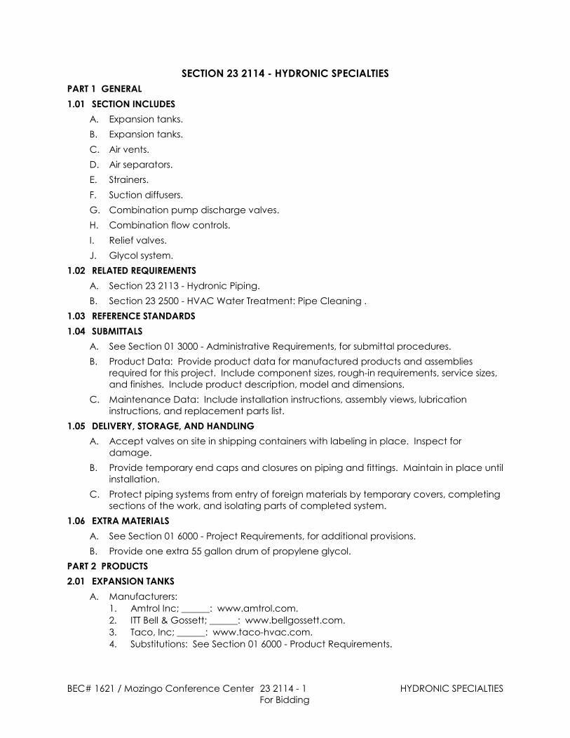
SECTION 23 2114 - HYDRONIC SPECIALTIESPART 1 GENERAL1.01 SECTION INCLUDES
A. Expansion tanks.B. Expansion tanks.C. Air vents.D. Air separators.E. Strainers.F. Suction diffusers.G. Combination pump discharge valves.H. Combination flow controls.I. Relief valves.J. Glycol system.
1.02 RELATED REQUIREMENTSA. Section 23 2113 - Hydronic Piping.B. Section 23 2500 - HVAC Water Treatment: Pipe Cleaning .
1.03 REFERENCE STANDARDS1.04 SUBMITTALS
A. See Section 01 3000 - Administrative Requirements, for submittal procedures.B. Product Data: Provide product data for manufactured products and assemblies
required for this project. Include component sizes, rough-in requirements, service sizes,and finishes. Include product description, model and dimensions.
C. Maintenance Data: Include installation instructions, assembly views, lubricationinstructions, and replacement parts list.
1.05 DELIVERY, STORAGE, AND HANDLINGA. Accept valves on site in shipping containers with labeling in place. Inspect for
damage.B. Provide temporary end caps and closures on piping and fittings. Maintain in place until
installation.C. Protect piping systems from entry of foreign materials by temporary covers, completing
sections of the work, and isolating parts of completed system.1.06 EXTRA MATERIALS
A. See Section 01 6000 - Project Requirements, for additional provisions.B. Provide one extra 55 gallon drum of propylene glycol.
PART 2 PRODUCTS2.01 EXPANSION TANKS
A. Manufacturers:1. Amtrol Inc; ______: www.amtrol.com.2. ITT Bell & Gossett; ______: www.bellgossett.com.3. Taco, Inc; ______: www.taco-hvac.com.4. Substitutions: See Section 01 6000 - Product Requirements.

BEC# 1621 / Mozingo Conference Center 23 2114 - 2 HYDRONIC SPECIALTIESFor Bidding
B. Construction: Welded steel, tested and stamped in accordance with ASMEBPVC-VIII-1; supplied with National Board Form U-1, rated for working pressure of 125 psi,with flexible EPDM diaphragm or bladder sealed into tank, and steel support stand.
C. Accessories: Pressure gage and air-charging fitting, tank drain; precharge to 12 psi.D. Automatic Cold Water Fill Assembly: Pressure reducing valve, reduced pressure double
check back flow preventer, test cocks, strainer, vacuum breaker, and valved by-pass.2.02 AIR VENTS
A. Manufacturers:1. Armstrong International, Inc; ______: www.armstronginternational.com.2. ITT Bell & Gossett; ______: www.bellgossett.com.3. Taco, Inc; ______: www.taco-hvac.com.
B. Manual Type: Short vertical sections of 2 inch diameter pipe to form air chamber, with1/8 inch brass needle valve at top of chamber.
2.03 AIR SEPARATORSA. Centrifugal Air Separators/Strainers:
1. Manufacturers:a. Armstrong International, Inc; ______: www.armstronginternational.com.b. ITT Bell & Gossett; ______: www.bellgossett.com.c. Taco, Inc; ______: www.taco-hvac.com.d. Spirovent
2. Steel, tested and stamped in accordance with ASME BPVC-VIII-1; for 125 psioperating pressure, with integral bronze strainer, tangential inlet and outletconnections, and internal stainless steel air collector tube.
2.04 STRAINERSA. Size 2 inch and Under:
1. Screwed brass or iron body for 175 psi working pressure, Y pattern with 1/32 inchstainless steel perforated screen.
B. Size 2-1/2 inch to 4 inch:1. Flanged iron body for 175 psi working pressure, Y pattern with 3/64 inch stainless
steel perforated screen.2.05 SUCTION DIFFUSERS
A. Fitting: Angle pattern, cast-iron body, threaded for 2 inch and smaller, flanged for 2-1/2inch and larger, rated for 175 psi working pressure, with inlet vanes, cylinder strainerwith 3/16 inch diameter openings, disposable 5/32 inch mesh strainer to fit over cylinderstrainer, 20 mesh start up screen, and permanent magnet located in flow stream andremovable for cleaning.
B. Fitting: Angle pattern, cast-iron body, threaded for 2 inch and smaller, flanged for 2-1/2inch and larger, rated for 175 psi working pressure, with inlet vanes, cylinder strainerwith 3/16 inch diameter openings, disposable fine mesh strainer to fit over cylinderstrainer, and permanent magnet located in flow stream and removable for cleaning.
C. Accessories: Adjustable foot support, blowdown tapping in bottom, gage tapping inside.
2.06 COMBINATION PUMP DISCHARGE VALVESA. Manufacturers:
1. ITT Bell & Gossett: http://fhs.ittind.com.

BEC# 1621 / Mozingo Conference Center 23 2114 - 3 HYDRONIC SPECIALTIES For Bidding
B. Valves: Straight or angle pattern, flanged cast-iron valve body with bolt-on bonnet for175 psi operating pressure, non-slam check valve with spring-loaded bronze disc andseat, stainless steel stem, and calibrated adjustment permitting flow regulation.
2.07 COMBINATION FLOW CONTROLSA. Construction: Brass or bronze body with union on inlet and outlet, temperature and
pressure test plug on inlet and outlet with blowdown/backflush drain.B. Calibration: Control flow within 5 percent of selected rating, over operating pressure
range of 10 times minimum pressure required for control, maximum minimum pressure3.5 psi.
C. Control Mechanism: Stainless steel or nickel plated brass piston or regulator cup,operating against stainless steel helical or wave formed spring.
D. Accessories: In-line strainer on inlet and ball valve on outlet.2.08 RELIEF VALVES
A. Bronze body, teflon seat, stainless steel stem and springs, automatic, direct pressureactuated, capacities ASME certified and labelled.
2.09 GLYCOL SYSTEMA. Storage Tank: Closed type, welded steel constructed, tested and stamped in
accordance with ASME BPVC-VIII-1; 100 psi rating; cleaned, prime coated, andsupplied with steel support saddles. Construct with tappings for installation ofaccessories.
B. Expansion Tank: Diaphragm type with vent fitting with air separator, and automatic airvent.
C. Air Pressure Reducing Station: Pressure reducing valve with shut-off valves, strainer,check valve and needle valve bypass.
D. Glycol Solution:1. Inhibited propylene glycol and water solution mixed 25 percent glycol - 75
percent water, suitable for operating temperatures from minus 40 degrees F-20degrees F to 250 degrees F.
PART 3 EXECUTION3.01 INSTALLATION
A. Install specialties in accordance with manufacturer's instructions.B. Provide manual air vents at system high points and as indicated.C. For automatic air vents in ceiling spaces or other concealed locations, provide vent
tubing to nearest drain.D. Provide air separator on suction side of system circulation pump and connect to
expansion tank.E. Provide valved drain and hose connection on strainer blow down connection.F. Provide pump suction fitting on suction side of base mounted centrifugal pumps where
indicated. Remove temporary strainers after cleaning systems.G. Provide combination pump discharge valve on discharge side of base mounted
centrifugal pumps where indicated.H. Support pump fittings with floor mounted pipe and flange supports.I. Provide relief valves on pressure tanks, low pressure side of reducing valves, heat
exchangers, and expansion tanks.

BEC# 1621 / Mozingo Conference Center 23 2114 - 4 HYDRONIC SPECIALTIES For Bidding
J. Select system relief valve capacity so that it is greater than make-up pressure reducingvalve capacity. Select equipment relief valve capacity to exceed rating ofconnected equipment.
K. Pipe relief valve outlet to nearest floor drain.L. Clean and flush glycol system before adding glycol solution. Refer to Section 23 2500.M. Feed glycol solution to system through make-up line with pressure regulator, venting
system high points.N. Feed glycol solution to system through make-up line with pressure regulator, venting
system high points. Set to fill at 12 psi.O. Perform tests determining strength of glycol and water solutions and submit written test
results for both heating water and chilled water systems.3.02 MAINTENANCE
A. See Section 01 7000 - Execution Requirements, for additional requirements relating tomaintenance service.
B. Provide service and maintenance of glycol system for one year from date ofSubstantial Completion at no extra charge to Owner.
C. Perform monthly visit to make glycol fluid concentration analysis on site with refractiveindex measurement instrument. Report findings in detail in writing, including analysisand amounts of glycol or water added.
D. Explain corrective actions to Owner's maintenance personnel in person.END OF SECTION
BEC# 1621 / Mozingo Conference Center 23 2123 - 1 HYDRONIC PUMPSFor Bidding
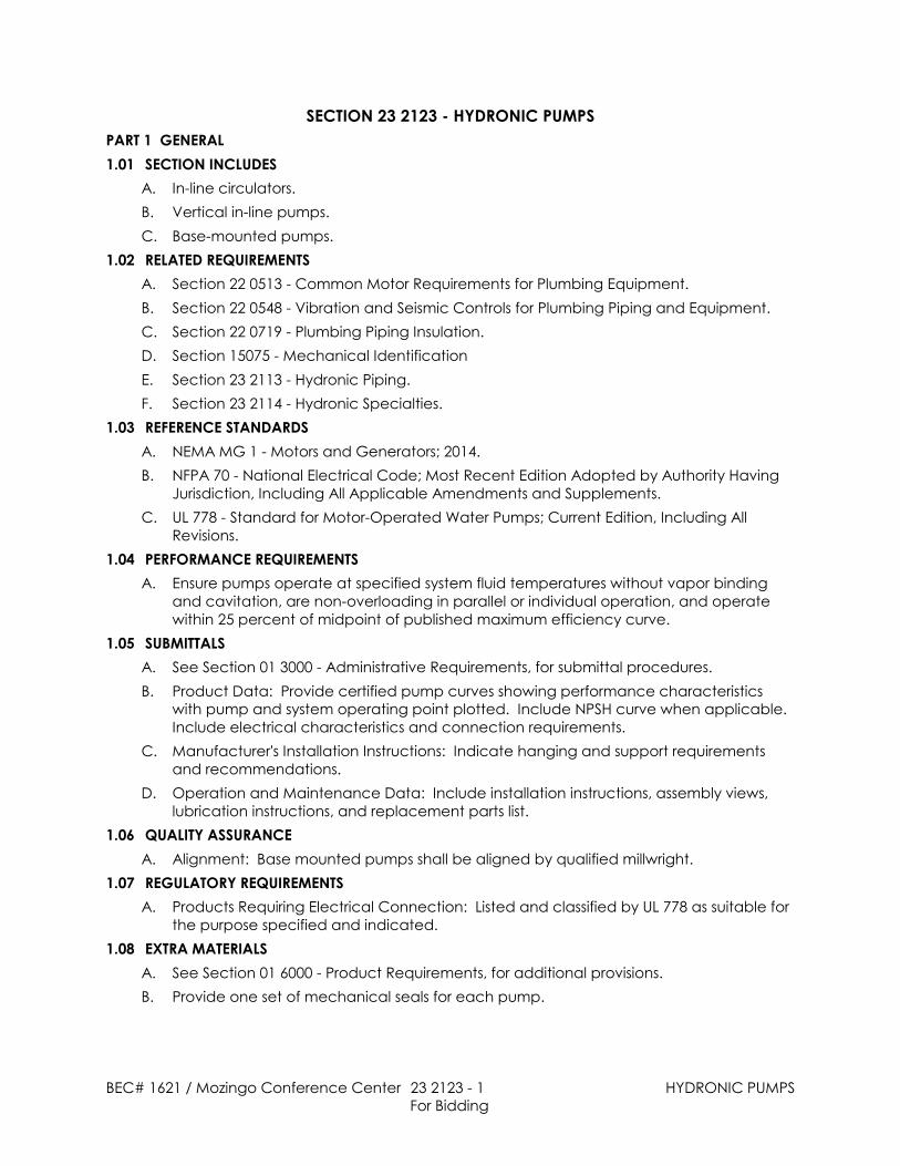
SECTION 23 2123 - HYDRONIC PUMPSPART 1 GENERAL1.01 SECTION INCLUDES
A. In-line circulators.B. Vertical in-line pumps.C. Base-mounted pumps.
1.02 RELATED REQUIREMENTSA. Section 22 0513 - Common Motor Requirements for Plumbing Equipment.B. Section 22 0548 - Vibration and Seismic Controls for Plumbing Piping and Equipment.C. Section 22 0719 - Plumbing Piping Insulation.D. Section 15075 - Mechanical IdentificationE. Section 23 2113 - Hydronic Piping.F. Section 23 2114 - Hydronic Specialties.
1.03 REFERENCE STANDARDSA. NEMA MG 1 - Motors and Generators; 2014.B. NFPA 70 - National Electrical Code; Most Recent Edition Adopted by Authority Having
Jurisdiction, Including All Applicable Amendments and Supplements.C. UL 778 - Standard for Motor-Operated Water Pumps; Current Edition, Including All
Revisions.1.04 PERFORMANCE REQUIREMENTS
A. Ensure pumps operate at specified system fluid temperatures without vapor bindingand cavitation, are non-overloading in parallel or individual operation, and operatewithin 25 percent of midpoint of published maximum efficiency curve.
1.05 SUBMITTALSA. See Section 01 3000 - Administrative Requirements, for submittal procedures.B. Product Data: Provide certified pump curves showing performance characteristics
with pump and system operating point plotted. Include NPSH curve when applicable. Include electrical characteristics and connection requirements.
C. Manufacturer's Installation Instructions: Indicate hanging and support requirementsand recommendations.
D. Operation and Maintenance Data: Include installation instructions, assembly views,lubrication instructions, and replacement parts list.
1.06 QUALITY ASSURANCEA. Alignment: Base mounted pumps shall be aligned by qualified millwright.
1.07 REGULATORY REQUIREMENTSA. Products Requiring Electrical Connection: Listed and classified by UL 778 as suitable for
the purpose specified and indicated.1.08 EXTRA MATERIALS
A. See Section 01 6000 - Product Requirements, for additional provisions.B. Provide one set of mechanical seals for each pump.
BEC# 1621 / Mozingo Conference Center 23 2123 - 2 HYDRONIC PUMPSFor Bidding
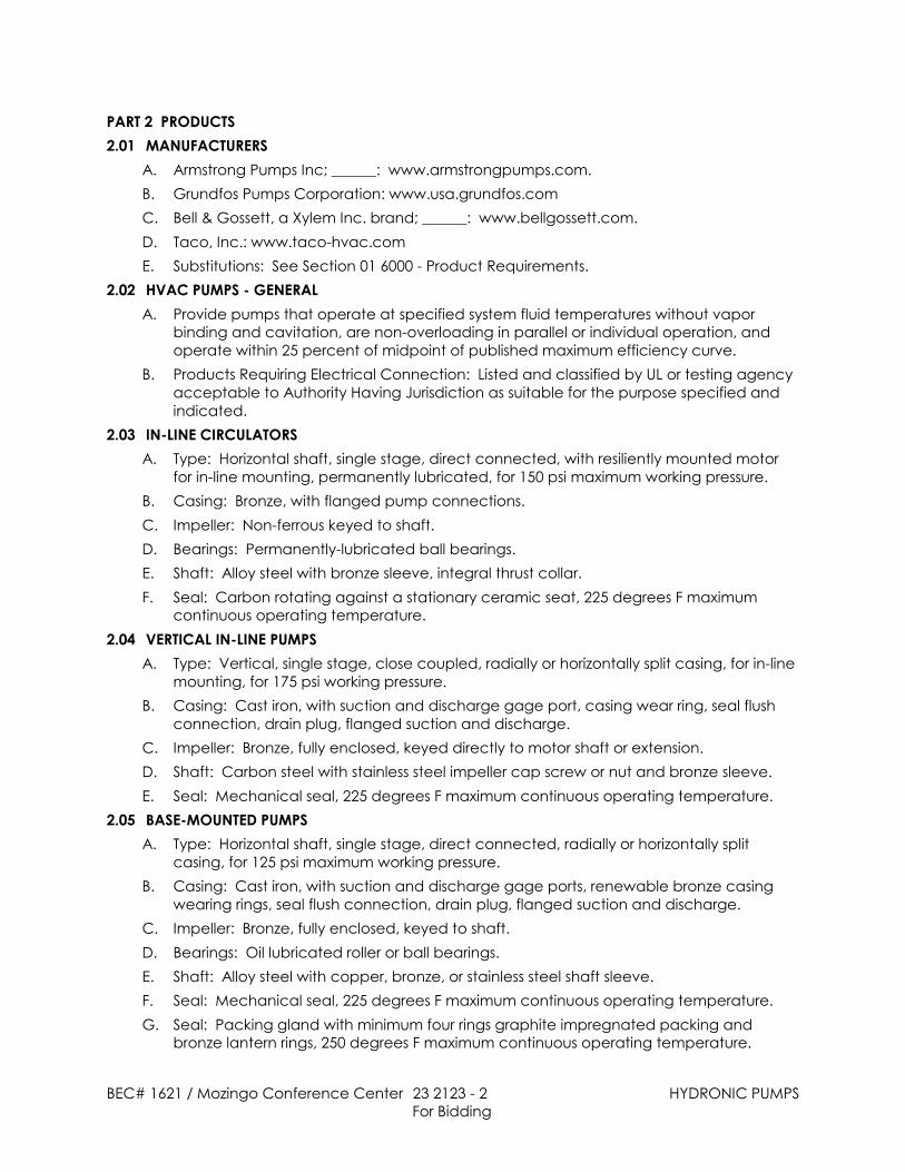
PART 2 PRODUCTS2.01 MANUFACTURERS
A. Armstrong Pumps Inc; ______: www.armstrongpumps.com.B. Grundfos Pumps Corporation: www.usa.grundfos.comC. Bell & Gossett, a Xylem Inc. brand; ______: www.bellgossett.com.D. Taco, Inc.: www.taco-hvac.comE. Substitutions: See Section 01 6000 - Product Requirements.
2.02 HVAC PUMPS - GENERALA. Provide pumps that operate at specified system fluid temperatures without vapor
binding and cavitation, are non-overloading in parallel or individual operation, andoperate within 25 percent of midpoint of published maximum efficiency curve.
B. Products Requiring Electrical Connection: Listed and classified by UL or testing agencyacceptable to Authority Having Jurisdiction as suitable for the purpose specified andindicated.
2.03 IN-LINE CIRCULATORSA. Type: Horizontal shaft, single stage, direct connected, with resiliently mounted motor
for in-line mounting, permanently lubricated, for 150 psi maximum working pressure.B. Casing: Bronze, with flanged pump connections.C. Impeller: Non-ferrous keyed to shaft.D. Bearings: Permanently-lubricated ball bearings.E. Shaft: Alloy steel with bronze sleeve, integral thrust collar.F. Seal: Carbon rotating against a stationary ceramic seat, 225 degrees F maximum
continuous operating temperature.2.04 VERTICAL IN-LINE PUMPS
A. Type: Vertical, single stage, close coupled, radially or horizontally split casing, for in-linemounting, for 175 psi working pressure.
B. Casing: Cast iron, with suction and discharge gage port, casing wear ring, seal flushconnection, drain plug, flanged suction and discharge.
C. Impeller: Bronze, fully enclosed, keyed directly to motor shaft or extension.D. Shaft: Carbon steel with stainless steel impeller cap screw or nut and bronze sleeve.E. Seal: Mechanical seal, 225 degrees F maximum continuous operating temperature.
2.05 BASE-MOUNTED PUMPSA. Type: Horizontal shaft, single stage, direct connected, radially or horizontally split
casing, for 125 psi maximum working pressure.B. Casing: Cast iron, with suction and discharge gage ports, renewable bronze casing
wearing rings, seal flush connection, drain plug, flanged suction and discharge.C. Impeller: Bronze, fully enclosed, keyed to shaft.D. Bearings: Oil lubricated roller or ball bearings.E. Shaft: Alloy steel with copper, bronze, or stainless steel shaft sleeve.F. Seal: Mechanical seal, 225 degrees F maximum continuous operating temperature.G. Seal: Packing gland with minimum four rings graphite impregnated packing and
bronze lantern rings, 250 degrees F maximum continuous operating temperature.

BEC# 1621 / Mozingo Conference Center 23 2123 - 3 HYDRONIC PUMPSFor Bidding
H. Drive: Flexible coupling with coupling guard.I. Baseplate: Cast iron or fabricated steel with integral drain rim.
PART 3 EXECUTION3.01 PREPARATION
A. Verify that electric power is available and of the correct characteristics.3.02 INSTALLATION
A. Install in accordance with manufacturer's instructions.B. Provide access space around pumps for service. Provide no less than minimum space
recommended by manufacturer.C. Decrease from line size with long radius reducing elbows or reducers. Support piping
adjacent to pump such that no weight is carried on pump casings. For close-coupledor base-mounted pumps, provide supports under elbows on pump suction anddischarge line sizes 4 inches and over. Refer to Section 22 0548.
D. Provide line sized shut-off valve and strainer on pump suction, and line sized soft seatcheck valve and balancing valve on pump discharge.
E. Provide air cock and drain connection on horizontal pump casings.F. Provide drains for bases and seals, piped to and discharging into floor drains.G. Check, align, and certify alignment of base-mounted pumps prior to start-up.H. Install base mounted pumps on concrete housekeeping base/pads using anchor bolts;
set and level; grout in place. Refer to Section 03300.I. Install other non-base mounted pumps on housekeeping pads with anchor bolts as
noted in the Project Drawings.J. Lubricate pumps before start-up.K. Provide side-stream filtration system for closed loop systems. Install across pump with
flow from pump discharge to pump suction from pump tappings.3.03 SCHEDULES
A. See Contract Drawings.END OF SECTION

1621 Mozingo Conference Center Addendum 2 10/4/2016
AREA POSITION TYPE THICKNESS DENSITY
GALVANIZED PER SMACNA FLANGED ORDRIVE 3" ALL EXTERIOR
FLEXIBLESEMI RIGIDFIBERGLASS
2.0" 1.5# ALUMINIZEDFOIL FACE 1,2,3,7
GALVANIZED PER SMACNA FLANGED ORDRIVE 3" ALL EXTERIOR
FLEXIBLESEMI RIGIDFIBERGLASS
2.0" 1.0# ALUMINIZEDFOIL FACE 1,2,3
GALVANIZED PER SMACNA FLANGED ORDRIVE 3" ALL EXTERIOR
FLEXIBLESEMI RIGIDFIBERGLASS
2.0" 1.5# ALUMINIZEDFOIL FACE 7
GALVANIZED PER SMACNA FLANGED ORDRIVE 3" ALL EXTERIOR FLEXIBLE
FIBERGLASS 2.0" 1.0# ALUMINIZEDFOIL FACE 6
GALVANIZED PER SMACNA FLANGED ORDRIVE 2" ALL EXTERIOR FLEXIBLE
FIBERGLASS 1.5" 1.0# ALUMINIZEDFOIL FACE 1,2,4
GALVANIZED PER SMACNA FLANGED ORDRIVE 2" ALL EXTERIOR FLEXIBLE
FIBERGLASS 1" 1.0# ALUMINUMFOIL FACED 1,2,4
GALVANIZED PER SMACNA FLANGED ORDRIVE 2" ALL EXTERIOR SEMI-RIGID
FIBERGLASS 1.5" 1.0# ALUMINIZEDFOIL FACE 1,2,4
GALVANIZED PER SMACNA FLANGED ORDRIVE 2" N/A N/A N/A N/A N/A N/A N/A
GALVANIZED PER SMACNA FLANGED ORDRIVE 1" ALL EXTERIOR FLEXIBLE
FIBERGLASS 1.5" 1.0# ALUMINIZEDFOIL FACE 1,2,4,5
STAINLESS STEEL PER SMACNA FLANGED ORDRIVE 1" ALL INTEGRAL FIRE WRAP 3" N/A ALUMINIZED
STEEL 1,2,4
GALVANIZED PER SMACNA FLANGED ORDRIVE 1" ALL INTERIOR FIBERGLASS
LINER 0.5" 1.0# ALUMINIZEDFOIL FACE 1,2,4
1.2.3.4.5.6.7.
RTU-1 RETURN(INTERIOR)
SEAL ALL DUCTWORK CLASS C.
EXTERIOR IS OUTSIDE OF FOUNDATION WALL, INSIDE DUCT TUNNEL.
RECTANGULAREXPOSEDSUPPLY
RECTANGULAREXPOSEDRETURN
TRANSFERDUCT
REMARKS:POSITIVE OR NEGATIVE PRESSURE CLASS.METAL DUCT AND INSULATION TO MAINTAIN CEILING FIRE RATING.
EXHAUST AIR(GREASE)
FURNACESUPPLY
FURNACERETURN
SEAL ALL DUCTWORK CLASS B.
INSULATE LAST 5' FROM OUTSIDE WALL OR ROOF PENETRATION.
EXHAUST/OUTSIDE AIR
INSULATE LAST 20' FROM OUTSIDE WALL.
RTU-1 SUPPLY(EXTERIOR)
RTU-1 RETURN(EXTERIOR)
DUCT SCHEDULEAREA OR USE CONSTRUCTION
MATERIAL GAUGE (MIN) JOINTS PRESSURECLASS
INSULATION JACKET REMARKS
RTU-1 SUPPLY(INTERIOR)
P:\2016\1621.MozingoConfCenter\CD\Equip\Mech\1621 Mech Schedule

1621 Mozingo Conference Center Addendum 2 10/4/2016
FAN SCHEDULEVOLT PH HP SWITCH STARTER
UPPER LEVELRESTROOMS INLINE 350 0.25 2.6 120 1 1/10 EC EC DIRECT YES GREENHECK SQ-85-VG 1,2,4,5
SINGLERESTROOM CEILING 75 0.25 0.9 120 1 1/10 EC EC DIRECT YES GREENHECK SP-B80 1,7
KITCHEN LOWERLEVEL
SIDEWALLCENTRIFUGAL 2,775 0.50 14.3 120 1 3/4 EC EC DIRECT YES GREENHECK CW-161-VG 1,5
KITCHEN LOWERLEVEL INLINE 2,775 0.50 4.9 120 1 1.25 NEMA1
NOTE 3 NOTE 4 DIRECT NO GREENHECK CSP-A3600 1,3,6
REMARKS:1.2.3.4.5.6.7.
REMARKSMARK SERVES TYPE AIRFLOW(CFM)
ESP(IN W.C.)
MAX SONES(dBA)
ELECTRICAL DATA BACKDRAFTDAMPER MANUFACTURER MODELDRIVE
EF-1
EF-2
FAN TO OPERATE WITH LIGHT SWITCH. PROVIDE BACKDRAFT DAMPER, WALL CAP, BIRDSCREEN, AND DISCONNECT SWITCH.
SWITCH TO BE INSTALLED AND WIRED AT FACTORY.
INSULATED HOUSING, VIBRATRION ISOLATION KIT.PROVIDE BACKDRAFT DAMPER, ROOF CAP, BIRDSCREEN, AND DISCONNECT SWITCH.
FAN TO OPERATE BY RELAY FROM KITCHEN EXHAUST HOOD MOTOR CONTROL CIRCUIT.
EF-3
TF-1
COORDINATE WITH THE ELECTRICAL CONTRACTOR CONTROL AND POWER REQUIREMENTS.FAN TO OPERATE DURING FACILITY'S OPERATING HOURS
P:\2016\1621.MozingoConfCenter\CD\Equip\Mech\1621 Mech Schedule

1621 Mozingo Conference Center Addendum 2 10/4/2016
NET CAP.(MBH) STAGES SEER EVAP. COIL
MODEL TYPEGAS
CONNSIZE
STAGES TEMP RISE(DEG F)
INPUT(MBH)
OUTPUT(MBH) AFUE (%) CFM OA (CFM) ESP
(IN W.C.) VOLT PH MCA MOCP SWITCH STARTER TYPE SIZE(IN)
CART STORAGE B CART STORAGE B N/A N/A N/A CH33-36B LP GAS .5" 2 35 32 30 96 800 N/A 0.25 120 1 6.8 15 NEMA1 TSTAT PLEATED 1 LENNOX EL296UH045XE36B 1,2,4CART STORAGE A CART STORAGE A N/A N/A N/A CH33-36B LP GAS .5" 2 49 66 64 96 1200 N/A 0.25 120 1 6.8 15 NEMA1 TSTAT PLEATED 1 LENNOX EL296UH045XE36B 1,2,4
CART STORAGE B STORAGE/MECH/RESTROOMS N/A N/A N/A CH33-60D LP GAS .5" 2 48 98 94 96 1800 1060 0.60 120 1 10.9 15 NEMA1 TSTAT PLEATED 1 LENNOX EL296UH135XE60D 1,2,4
CART STORAGE A CLUBHOUSE N/A N/A N/A CH33-60D LP GAS .5" 2 21 56 53 96 2320 765 0.79 120 1 10.9 15 NEMA1 TSTAT PLEATED 1 LENNOX EL296UH135XE60D 1,2,4CART STORAGE A CLUBHOUSE N/A N/A N/A CH33-60D LP GAS .5" 2 21 56 53 96 2320 765 0.75 120 1 10.9 15 NEMA1 TSTAT PLEATED 1 LENNOX EL296UH135XE60D 1,2,4
CART STORAGE A OFFICES/HITTING BAYS N/A N/A N/A CH33-60D LP GAS .5" 2 30 55 52 96 1600 420 0.7 120 1 10.9 15 NEMA1 TSTAT PLEATED 1 LENNOX EL296UH135XE60D 1,2,4
CART STORAGE A CLUBHOUSE N/A N/A N/A CH33-60D LP GAS .5" 2 21 56 53 96 2320 765 0.8 120 1 10.9 15 NEMA1 TSTAT PLEATED 1 LENNOX EL296UH135XE60D 1,2,4CART STORAGE A PROSHOP N/A N/A N/A CH33-48 LP GAS .5" 2 20 42 40 96 1850 200 0.63 120 1 8.4 15 NEMA1 TSTAT PLEATED 1 LENNOX EL296UH090XE48C 1,2,4
CORRIDOR KITCHEN N/A N/A N/A CH33-60D LP GAS .5" 2 23 56 53 96 2100 N/A 0.75 120 1 10.9 15 NEMA1 TSTAT PLEATED 1 LENNOX EL296UH135XE60D 1,2,4SEE DRWG F-1 3 2 14.0 N/A N/A N/A N/A N/A N/A N/A N/A N/A N/A N/A 460 3 8 10 NEMA3R EC N/A N/A LENNOX SSB036H4S41G 1,3SEE DRWG F-2 3 2 14.0 N/A N/A N/A N/A N/A N/A N/A N/A N/A N/A N/A 460 3 8 10 NEMA3R EC N/A N/A LENNOX SSB036H4S41G 1,3SEE DRWG F-3 5 2 15.0 N/A N/A N/A N/A N/A N/A N/A N/A N/A N/A N/A 460 3 10 20 NEMA3R EC N/A N/A LENNOX SSB060H4S41G 1,3SEE DRWG F-4 5 2 15.0 N/A N/A N/A N/A N/A N/A N/A N/A N/A N/A N/A 460 3 10 20 NEMA3R EC N/A N/A LENNOX SSB060H4S41G 1,3SEE DRWG F-5 5 2 15.0 N/A N/A N/A N/A N/A N/A N/A N/A N/A N/A N/A 460 3 10 20 NEMA3R EC N/A N/A LENNOX SSB060H4S41G 1,3SEE DRWG F-6 5 2 15.0 N/A N/A N/A N/A N/A N/A N/A N/A N/A N/A N/A 460 3 10 20 NEMA3R EC N/A N/A LENNOX SSB060H4S41G 1,3SEE DRWG F-7 5 2 15.0 N/A N/A N/A N/A N/A N/A N/A N/A N/A N/A N/A 460 3 10 20 NEMA3R EC N/A N/A LENNOX SSB060H4S41G 1,3SEE DRWG F-8 4 2 15.0 N/A N/A N/A N/A N/A N/A N/A N/A N/A N/A N/A 460 3 9 15 NEMA3R EC N/A N/A LENNOX SSB048H4S41G 1,3SEE DRWG F-9 5 2 15.0 N/A N/A N/A N/A N/A N/A N/A N/A N/A N/A N/A 460 3 10 20 NEMA3R EC N/A N/A LENNOX SSB060H4S41G 1,3
REMARKS:1.2.3.4.
PROVIDE COOLING COILS, CONCRETE PADS, LINES SETS, CRANK CASE HEATERS AND LOW AMBIENT KITS TO 30 DEGREES F FOR CONDENSING UNITS.
F-9 1
ACCU-9 1/3
PROVIDE PREMIUM 7 DAY PROGRAMMABLE THERMOSTAT, LENNOX COMFORTSENSE 7500 WITH 2 STAGE HEATING AND COOLING, BLOWER FAN AND DAMPER CONTROL.PROVIDE PROPER VENT AND INTAKE PIPING PER MANUFACTURERS INSTRUCTIONS.
1/3ACCU-8 1/3
FURNACE AND CONDENSING UNIT SCHEDULE
MARK LOCATION SERVES
COOLING HEATING BLOWER ELECTRICAL DATA FILTER
MANUFACTURER MODEL REMARKSHP
1
ACCU-1 1/4ACCU-2 1/4
F-3 1
F-4 1F-5 1
F-2 1F-1
PROVIDE NATURAL GAS TO LPG/PROPANE CONVERSION KIT FOR EACH FURNACE.
F-6 1
F-7 1
ACCU-6
ACCU-3 1/3ACCU-4 1/3ACCU-5 1/3
F-8 1
1/3ACCU-7
P:\2016\1621.MozingoConfCenter\CD\Equip\Mech\1621 Mech Schedule
1621 Mozingo Conference Center Addendum 2 10/4/2016
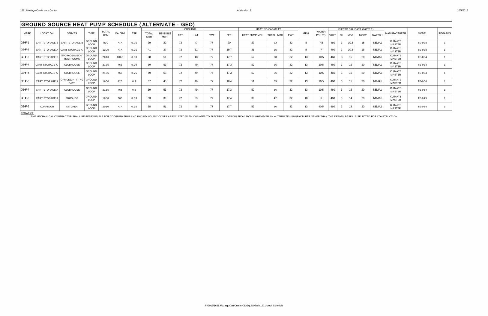
TOTALMBH
SENSIBLEMBH
EAT LAT EWT EER HEAT PUMP MBH TOTAL MBH EWT VOLT PH MCA MOCP SWITCH
CART STORAGE B CART STORAGE B GROUNDLOOP
800 N/A 0.25 39 22 72 47 77 20 29 32 32 8 7.5 460 3 10.3 15 NEMA1 CLIMATEMASTER
TE-038 1
CART STORAGE A CART STORAGE AGROUND
LOOP 1200 N/A 0.25 41 27 72 51 77 19.7 31 66 32 8 7 460 3 10.3 15 NEMA1 CLIMATEMASTER TE-038 1
CART STORAGE B STORAGE/MECH/RESTROOMS
GROUNDLOOP
2010 1060 0.60 68 51 72 48 77 17.7 52 98 32 13 10.5 460 3 15 20 NEMA1 CLIMATEMASTER
TE-064 1
CART STORAGE A CLUBHOUSE GROUNDLOOP
2165 765 0.79 69 53 72 49 77 17.3 52 56 32 13 10.5 460 3 15 20 NEMA1 CLIMATEMASTER
TE-064 1
CART STORAGE A CLUBHOUSE GROUNDLOOP
2165 765 0.75 69 53 72 49 77 17.3 52 56 32 13 10.5 460 3 15 20 NEMA1 CLIMATEMASTER
TE-064 1
CART STORAGE A OFFICES/HITTINGBAYS
GROUNDLOOP
1600 420 0.7 67 45 72 46 77 18.4 51 55 32 13 10.5 460 3 15 20 NEMA1 CLIMATEMASTER
TE-064 1
CART STORAGE A CLUBHOUSE GROUNDLOOP
2165 765 0.8 69 53 72 49 77 17.3 52 56 32 13 10.5 460 3 15 20 NEMA1 CLIMATEMASTER
TE-064 1
CART STORAGE A PROSHOP GROUNDLOOP
1850 200 0.63 53 39 72 53 77 17.4 39 42 32 10 6 460 3 14 20 NEMA1 CLIMATEMASTER
TE-049 1
CORRIDOR KITCHEN GROUNDLOOP
2010 N/A 0.75 68 51 72 48 77 17.7 52 56 32 13 40.5 460 3 15 20 NEMA2 CLIMATEMASTER
TE-064 1
REMARKS:1.
GSHP-5
GSHP-9
THE MECHANICAL CONTRACTOR SHALL BE RESPONSIBLE FOR COORDINATING AND INCLUDING ANY COSTS ASSOCIATED WITH CHANGES TO ELECTRICAL DESIGN PROVISIONS WHENEVER AN ALTERNATE MANUFACTURER OTHER THAN THE DESIGN BASIS IS SELECTED FOR CONSTRUCTION.
GSHP-6
GSHP-7
GSHP-8
GSHP-4
GPM WATERPD (FT)
GSHP-1
GSHP-2
GSHP-3
GROUND SOURCE HEAT PUMP SCHEDULE (ALTERNATE - GEO)MARK LOCATION SERVES TYPE TOTAL
CFMOA CFM ESP
COOLING HEATING CAPACITYMODEL REMARKS
ELECTRICAL DATA (NOTE 1)MANUFACTURER
P:\2016\1621.MozingoConfCenter\CD\Equip\Mech\1621 Mech Schedule

1621 Mozingo Conference Center Addendum 2 10/4/2016
TYPE THICKNESS JACKET
ALL ACR SOLDER ORMECHANICAL JOINT WROUGHT COPPER CLOSED CELL 1/2" ASJ 3
ALL TYPE "L" COPPER SOLDER ORMECHANICAL JOINT WROUGHT COPPER PREFORMED
FIBERGLASS 1/2" N/A
RUNOUTS UPTO 1-1/2"
PREFORMEDFIBERGLASS 1.0" ASJ 1,2
1-1/2"-4" PREFORMEDFIBERGLASS 1-1/2" ASJ 1
RUNOUTS UPTO 1-1/2"
PREFORMEDFIBERGLASS 1/2" ASJ 1,2
1-1/2"-4" PREFORMEDFIBERGLASS 1.0" ASJ 1
3" ANDSMALLER
ANNEALEDCOPPER
FLARED(NONE UNDERGROUND) WROUGHT COPPER N/A N/A N/A 6
LARGERTHAN 3" DUCTILE IRON RUBBER GASKET DUCTILE IRON N/A N/A N/A 6
ALL S40 BLACKCARBON STEEL
THREADED ORMECHANICAL JOINT MALLEABLE IRON N/A N/A N/A 5
ALL S40 BSP WRAPPEDOR PE WELDED OR FUSED EPOXY RISERS N/A N/A N/A 6
ALL PVC SOLVENT WELD PVC SOCKET N/A N/A N/A NONE
ALLPVC
STD WEIGHTCAST IRON
SOLVENT WELDCAST IRON HUBLESS
PVC SOCKETCAST IRON HUBLESS N/A N/A N/A 6
ALL CAST IRON MECHANICAL JOINT DUCTILE IRON PREFORMEDFIBERGLASS 1" ASJ 4
1.2.3.4.5.6.
SANITARY WASTEBELOW GRADE
PROPANE GASABOVE GRADE
PRPANE GASBELOW GRADE
WELD ALL GAS PIPING JOINTS CONCEALED IN BUILDING CONSTRUCTION OR PLENUMS PER NFPA 54.
PVC JACKETING IN ALL MECHANICAL AREASINSULATE RUNOUTS LONGER THAN 5' AS PIPING.
REMARKS:
INSULATE WITH CLOSED CELL INSULATION AND PAINT WITH UV PROTECTANT PER MANUFACTURER'S INSTRUCTIONS.
SANITARY VENT
MECHANICAL JOINT WROUGHT COPPER
DOMESTIC COLD WATERBELOW GRADE
SANITARY WASTEABOVE GRADE
A/C REFRIGERANT
DOMESTIC HOT &RECIRC WATERABOVE GRADE
A/C CONDENSATE
PROVIDE TRACEABLE WARNING/MARKER TAPE FOR UNDERGROUND PIPING, LABELED WITH PIPING SERVICE.
ONLY INSULATE VENT PIPING WITHIN 3' OF ROOF OR EXTERIOR WALL PENETRATION.
PLUMBING PIPING SCHEDULEAREA OR USE SIZE TYPE JOINTS FITTINGS INSULATION REMARKS
TYPE "L" COPPER MECHANICAL JOINT WROUGHT COPPER
DOMESTIC COLD WATERABOVE GRADE TYPE "L" COPPER
P:\2016\1621.MozingoConfCenter\CD\Equip\Mech\1621_PlumbingFixtures
1621 Mozingo Conference Center Addendum 2 10/4/2016
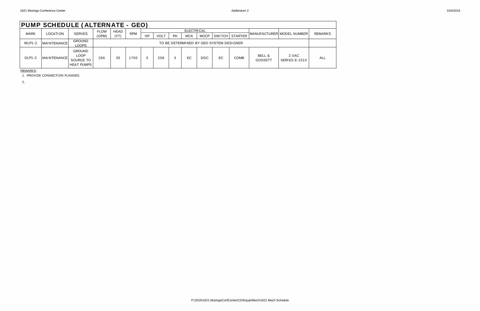
HP VOLT PH MCA MOCP SWITCH STARTER
MAINTENANCE GROUNDLOOPS
MAINTENANCE
GROUNDLOOP
SOURCE TOHEAT PUMPS
266 35 1750 3 208 3 EC DDC EC COMB BELL &GOSSETT
2.5ACSERIES E-1510 ALL
1.
2.
REMARKS:
REMARKS
WLP1-2
GLP1-2
PROVIDE CONNECTION FLANGES.
TO BE DETERMINED BY GEO SYSTEM DESIGNER
PUMP SCHEDULE (ALTERNATE - GEO)MARK LOCATION SERVES FLOW
(GPM)HEAD(FT) RPM
ELECTRICALMANUFACTURER MODEL NUMBER
P:\2016\1621.MozingoConfCenter\CD\Equip\Mech\1621 Mech Schedule

1621 Mozingo Conference Center Addendum 2 10/4/2016
GROSS(MBH)
NET(MBH)
DB(°F)
WB(°F)
DB(°F)
WB(°F) CFM OA
CFM
ESP(INWC)
HP CFMESP(INWC)
HP VOLT PH FLA MCA MOCP SWITCH TYPE NO. THICKNESS(IN)
UPPER LEVEL 60.0 11.3 801.0 756.0 75.6 63.7 52.8 51.3 895 68.0 2 1 R410A 18000 3,650 2.00 15.0 18000 2.42 7.5 460 3 159 165 175 NF MERV 8 24 2 14" INS AAON RN-60 ALL
REMARKS:1.2.3.5.6.7.8.9.
PROVIDE WITH COIL GUARDS, FACTORY DISCONNECT SWITCH, GFCI OUTLET, SMOKE DETECTOR TERMINALS, CRANK CASE HEATER & LOW AMBIENT KIT DOWN TO 0 DEGREE F.PROVIDE TURNING VANES FOR ALL ELBOWS.PROVIDE WITH TERMINAL STRIP INTERFACE FOR CONTROLS PROVIDED AND INSTALLED BY OTHERS.PROVIDE SOUND DEADENING BAFFLES AND VIBRATON ISOLATION ROOF CURBS.
UNIT SHALL INCLUDE ENERGY RECOVERY WHEELMULTI-ZONE VAV UNIT.
EWT (°F)
PROVIDE WITH FULL ECONOMIZER, POWER EXHAUST AND CORRESPONDING DAMPERS.
BLOWER SUPPLY BLOWER EXHAUST FILTERSROOF CURB
HEIGHT/TYPENO. STAGES OFUNLOADING REFRIG.
RTU-1
THE MECHANICAL CONTRACTOR SHALL BE RESPONSIBLE FOR COORDINATING AND INCLUDING ANY COSTS ASSOCIATED WITH CHANGES TO ELECTRICAL DESIGN PROVISIONS WHENEVER AN ALTERNATE MANUFACTURER OTHER THAN THE DESIGN BASIS IS SELECTED FOR CONSTRUCTION.
ROOFTOP UNIT SCHEDULE (ALTERNATE - GEO)
MARK SERVESNOMINAL
SIZE(TONS)
EER
ELECTRIC COOLING ELECTRIC HEATING COMPRESSORS ELECTRICAL DATA (NOTE 1)
MANUFACTURER MODEL REMARKSTOTAL EAT LAT
TOTAL MBH
P:\2016\1621.MozingoConfCenter\CD\Equip\Mech\1621 Mech Schedule

1621 Mozingo Conference Center Addendum 2 10/4/2016
LAT NUMBER OFSTEPS VOLT PH
UPPER KITCHEN 14 RTU-1 2170 651 1296 651 0.25 79.3 3 480 3 NAILOR D30RE ALLVAV-9 10.0
VAV BOX SCHEDULE - SINGLE DUCT ELECTRIC REHEAT
MARK SERVESMINIMUM
INLETSIZE
AHUSERVING
VAV
MINCOOLINGAIRFLOW
(CFM)
MINHEATINGAIRFLOW
(CFM)
AIRSIDEPRESSURE
DROP
HEATING COIL ELECTRICAL DATA(NOTE 1)
MANUFACTURER MODEL REMARKS
MAXCOOLINGAIRFLOW
(CFM)
MAXHEATINGAIRFLOW
(CFM) KW
P:\2016\1621.MozingoConfCenter\CD\Equip\Mech\1621 Mech Schedule

# Description Date# Addendum 10/4/16
1"1/2"0
SCALE REDUCTION BAR
1"1/2"0
SCALE REDUCTION BAR
# Description Date# Addendum 10/4/16
# Description Date# Addendum 10/4/16

# Description Date# Addendum 10/4/16
1"1/2"0
SCALE REDUCTION BAR
# Description Date# Addendum 10/4/16

1"1/2"0
SCALE REDUCTION BAR
# Description Date# Addendum 10/4/16

# Description Date# Addendum 10/4/16

1"1/2"0
SCALE REDUCTION BAR
# Description Date# Addendum 10/4/16
1"1/2"0
SCALE REDUCTION BAR
# Description Date# Addendum 10/4/16