medium voltage product vt guard solution for ... · pdf filevt guard solution for...
TRANSCRIPT
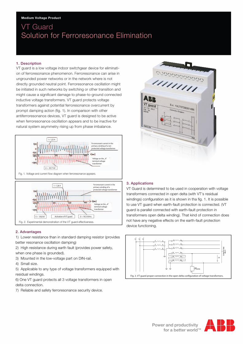
1. Description
VT GuardSolution for Ferroresonance Elimination
Medium Voltage Product
VT guard is a low voltage indoor switchgear device for eliminati-on of ferroresonance phenomenon. Ferroresonance can arise in ungrounded power networks or in the network where is not directly grounded neutral point. Ferroresonance oscillation might be initiated in such networks by switching or other transition and might cause a significant damage to phase-to-ground connected inductive voltage transformers. VT guard protects voltage transformers against potential ferroresonance overcurrent by prompt damping action (fig. 1). In comparison with other antiferroresonance devices, VT guard is designed to be active when ferroresonance oscillation appears and to be inactive for natural system asymmetry rising up from phase imbalance.
2. Advantages1) Lower resistance than in standard damping resistor (provides better resonance oscillation damping) 2) High resistance during earth fault (provides power safety, when one phase is grounded).3) Mounted in the low-voltage part on DIN-rail.4) Small size.5) Applicable to any type of voltage transformers equipped with residual windings.6) One VT guard protects all 3 voltage transformers in open delta connection.7) Reliable and safety ferroresonance security device.
3. Applications VT Guard is determined to be used in cooperation with voltage transformers connected in open delta (with VT’s residual windings) configuration as it is shown in tha fig. 1. It is possible to use VT guard when earth-fault protection is connected. (VT guard is parallel connected with earth-fault protection in transformers open delta winding). That kind of connection does not have any negative effects on the earth-fault protection device functioning.
Fig. 1. Voltage and current flow diagram when ferroresonance appears.
Fig. 2. Experimental demonstration of the VT guard effectiveness.
Voltage on the „A”terminal voltagetransformer
Feroresonant current in theprimary winding of a not-protected voltage transformer
Voltage on the „A”terminal voltagetransformer
Feroresonant current in theprimary winding of a protected voltage transformer
I = 1,28 A
U = -39,8 kV Activation of VT guard U = 14,13 kVms
I = 1,25 A
U = -39,71 kV
Medium Voltage Product
Fig. 3. VT guard proper connection in the open delta con�guration of voltage transformers.
4. Electrical and technical parametersRated voltage ......................................100 – 200 V VInsensibility zone ................................0 – 20 VDamping time at 100V .........................1 sAmbient temperature ...........................-10 °C to +55 °CHumidity ..............................................up to 90%The lowest allowed temperature for the transportation and storage ...................-30°CRed LED diode ....................................earth fault
7. WarrantyThe manufacturer warranty is 24 months since the day of putting the apparatus into operation but not longer than 36 months since the day of purchase.
5. Dimensional drawingDimensions (in mm) are shown on the fig. 4..
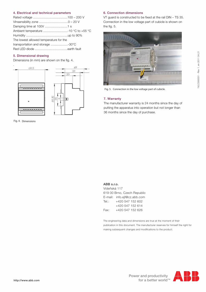
6. Connection dimensionsVT guard is constructed to be fixed at the rail DIN – TS 35. Connection in the low voltage part of cubicle is shown on the fig. 5.
Fig. 4. Dimensions
Fig. 5. Connection in the low voltage part of cubicle. 1VLC
0000
31 -
Rev
1,
en 2
011
04.2
1
ABB s.r.o.Vídeňská 117 619 00 Brno, Czech Republic E-mail: [email protected] Tel.: +420 547 152 602 +420 547 152 614Fax: +420 547 152 626
The engineering data and dimensions are true at the moment of their
publication in this document. The manufacturer reserves for himself the right for
making subsequent changes and modifications to the product.
http://www.abb.com