micokit-3166 development kit hardware...
TRANSCRIPT
Shanghai MXCHIP Information Technology Co., Ltd. Address:Floor 9, Building 5, No. 2145, Putuo District, Shanghai (200333) Telephone:021-52709556 Website:http://mxchip.com/
MiCOKit-3166 Development Kit Hardware Manual
Abstract
MiCOKit from MXCHIP is one development kit based on MiCO. It could be used for the development of smart
devices and the demos. This development kit provides one easy solution for developing smart devices. And it’s
convenient in achieving the applications of users.
More Help
Please login the website: http://mxchip.com/ to get Mxchip's latest product information.
Hardware Engineering Department Working Group Jing Minhua
Track Number: RM0087EN MXCHIP Co., Ltd
Version: 1.1 July 2017
Category: Reference Manual Open
MiCOKit-3166 Development Kit Hardware Manual [Page 1]
RM0087EN
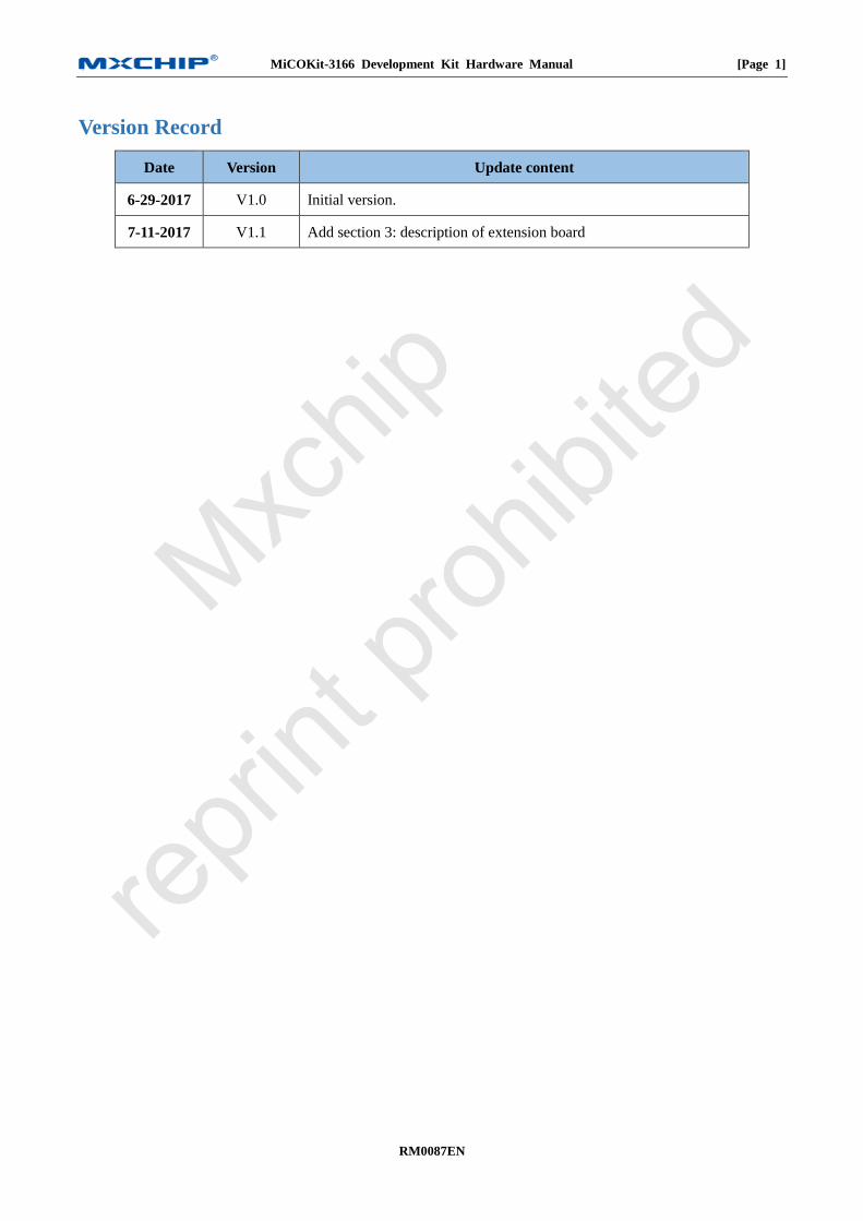
Version Record
Date Version Update content
6-29-2017 V1.0 Initial version.
7-11-2017 V1.1 Add section 3: description of extension board
MiCOKit-3166 Development Kit Hardware Manual [Page 2]
RM0087EN
Catalog
MiCOKit-3166 Development Kit Hardware Manual ...................................................................................................... 1
Version Record .................................................................................................................................................................... 1
1. Overview ...................................................................................................................................................................... 4
Hardware .......................................................................................................................................................... 4 1.1
Software ........................................................................................................................................................... 5 1.2
Support for developers ..................................................................................................................................... 5 1.3
2. Main board .................................................................................................................................................................. 6
Power ............................................................................................................................................................... 6 2.1
USB to UART .................................................................................................................................................. 7 2.2
Wi-Fi module ................................................................................................................................................... 8 2.3
LED lights ........................................................................................................................................................ 9 2.4
Working mode ................................................................................................................................................ 10 2.5
Buttons ........................................................................................................................................................... 10 2.6
JTAG debug connector................................................................................................................................... 10 2.7
Arduino connector ......................................................................................................................................... 11 2.8
Schematics ..................................................................................................................................................... 12 2.9
PCB ................................................................................................................................................................ 13 2.10
3. Extension board ........................................................................................................................................................ 15
OLED screen.................................................................................................................................................. 16 3.1
RGB LED ...................................................................................................................................................... 16 3.2
Environment sensor (optional) ....................................................................................................................... 17 3.3
Nine axis motion sensor (optional) ................................................................................................................ 18 3.4
Range& solar sensor ...................................................................................................................................... 18 3.5
Temperature& humidity sensor ...................................................................................................................... 19 3.6
Infrared reflection switch ............................................................................................................................... 20 3.7
Solar sensor .................................................................................................................................................... 20 3.8
Mini-type DC motor ...................................................................................................................................... 21 3.9
Standard Arduino connector .......................................................................................................................... 21 3.10
Arduino sensor connector .............................................................................................................................. 22 3.11
UART connector ............................................................................................................................................ 22 3.12
Schematic of extension board ........................................................................................................................ 23 3.13
MiCOKit-3166 Development Kit Hardware Manual [Page 3]
RM0087EN
Picture Catalog
Figure 1 MiCOKit Development Board .............................................................................................................. 4
Figure 2 MiCOKit-3166 Main Board .................................................................................................................. 6
Figure 3 The Circuit of Power Supply ................................................................................................................. 7
Figure 4 USB to UART Circuit ........................................................................................................................... 8
Figure 5 Serial Installing ..................................................................................................................................... 8
Figure 6 EMW3166 ............................................................................................................................................. 9
Figure 7 LED Circuit ........................................................................................................................................... 9
Figure 8 Buttons ................................................................................................................................................ 10
Figure 9 JTAG Connector ................................................................................................................................... 11
Figure 10 Arduino Connector ............................................................................................................................. 11
Figure 11 MiCOKit Extender Board .................................................................................................................. 15
Figure 12 OLED Screen Circuit ........................................................................................................................ 16
Figure 13 RGB Driver Circuit ........................................................................................................................... 17
Figure 14 P9813 Driver Timer ........................................................................................................................... 17
Figure 15 Environment Sensor Circuit .............................................................................................................. 17
Figure 16 Nine-axis Motion Sensor Circuit ....................................................................................................... 18
Figure 17 APPLE CP Circuit ............................................................................................................................. 18
Figure 18 Range& Solar Sensor Circuit ............................................................................................................ 19
Figure 19 Temperature& Humidity Sensor Circuit ............................................................................................ 19
Figure 20 DHT11 Timing .................................................................................................................................. 20
Figure 21 Infrared Reflection Sensor Circuit..................................................................................................... 20
Figure 22 Solar Sensor Circuit .......................................................................................................................... 21
Figure 23 DC Motor Circuit .............................................................................................................................. 21
Figure 24 Extender Board Arduino Circuit ........................................................................................................ 22
Figure 25 Arduino Sensor Connector Circuit .................................................................................................... 22
Figure 26 UART Connector Circuit ................................................................................................................... 22
Figure 27 Schematic of extension board ............................................................................................................ 23
Table Catalog
Table 1 Working Mode ...................................................................................................................................... 10
MiCOKit-3166 Development Kit Hardware Manual [Page 4]
RM0087EN
1. Overview
MiCOKit from MXCHIP is one development kit based on MiCO. It could be used for the development of smart
devices and the demos. This development kit provides one easy solution for developing smart devices. And it’s
convenient in achieving the applications of users.
MiCOKit features:
Based on MiCO, high efficiency, safe and easy to use;
Sufficient peripherals;
Various Demos and perfect MiCOKit SDK are available;
The kits include hardware, software and community parts with MiCOKit development board and the demos about
how to connect to cloud platform to achieve the controlling by mobile phone.
FogCloud service is prepared;
Interaction with phone and PC;
Interface for main third cloud platform: Aliyun, Microsoft, Amazon, IBM, Wechat, AirKiss, Ayla,
FogCloud, GizWits, Haier U+, Arrayent and so on;
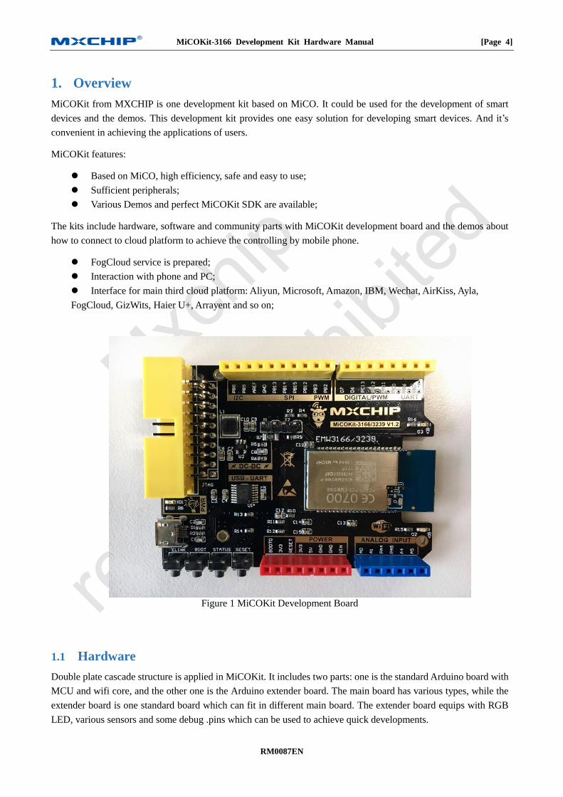
Figure 1 MiCOKit Development Board
Hardware 1.1
Double plate cascade structure is applied in MiCOKit. It includes two parts: one is the standard Arduino board with
MCU and wifi core, and the other one is the Arduino extender board. The main board has various types, while the
extender board is one standard board which can fit in different main board. The extender board equips with RGB
LED, various sensors and some debug .pins which can be used to achieve quick developments.
MiCOKit-3166 Development Kit Hardware Manual [Page 5]
RM0087EN
Part number: MiCOKit-3166 (including both baseboard and extension board)
MiCOKit-base-3166 (baseboard only)
Software 1.2
MiCOKit is based on MiCO. Developers can easily develop their own product by using supplied SDK which takes
the features of IoT developing.
One completed cloud platform service is already available. Developers could see the sensor data and control the
devices on board by using FogCloud service and APP “MICO enjoy” in order to achieve the interaction between
mobile phone and MiCOKit.
Support for developers 1.3
One account of MiCO developers’ community and the privilege for developing support are provided by using
MiCOKit. It includes the necessary developing resources, SDK, MiCO community and the information about how
to connect to other cloud platforms by using interfaces in software frame provided by MXCHIP.
MiCO developers’ community: www.MiCO.io.
MiCOKit-3166 Development Kit Hardware Manual [Page 6]
RM0087EN
2. Main board
MiCOKit-3166 applies the Wi-Fi module with Arduino standard, main components:
EMW3166 from MXCHIP;
2Mbyte build-in SPI flash within EMW3166;
Demos about solution of MiCO-Cloud-APP for secondary development;
USB to UART serial port for debugging;
3 indicator LED of working status;
Power supply: Micro-USB 5V with one DC-DC onboard 5V-3.3V.
JTAG/SWD debug connector;
Pins for Arduino extender board;
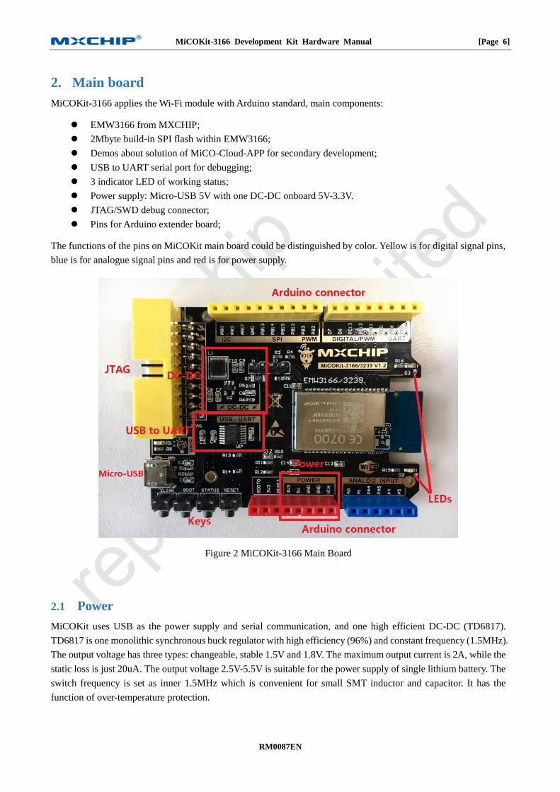
The functions of the pins on MiCOKit main board could be distinguished by color. Yellow is for digital signal pins,
blue is for analogue signal pins and red is for power supply.
Figure 2 MiCOKit-3166 Main Board
Power 2.1
MiCOKit uses USB as the power supply and serial communication, and one high efficient DC-DC (TD6817).
TD6817 is one monolithic synchronous buck regulator with high efficiency (96%) and constant frequency (1.5MHz).
The output voltage has three types: changeable, stable 1.5V and 1.8V. The maximum output current is 2A, while the
static loss is just 20uA. The output voltage 2.5V-5.5V is suitable for the power supply of single lithium battery. The
switch frequency is set as inner 1.5MHz which is convenient for small SMT inductor and capacitor. It has the
function of over-temperature protection.
MiCOKit-3166 Development Kit Hardware Manual [Page 7]
RM0087EN
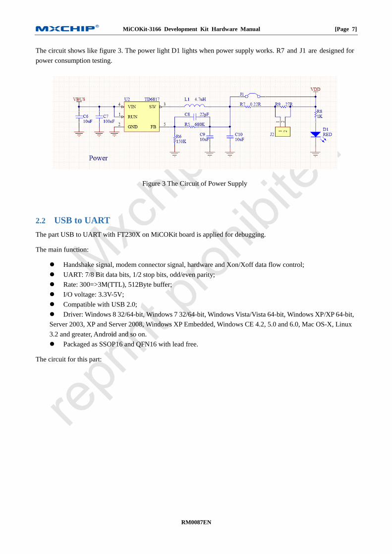
The circuit shows like figure 3. The power light D1 lights when power supply works. R7 and J1 are designed for
power consumption testing.
Figure 3 The Circuit of Power Supply
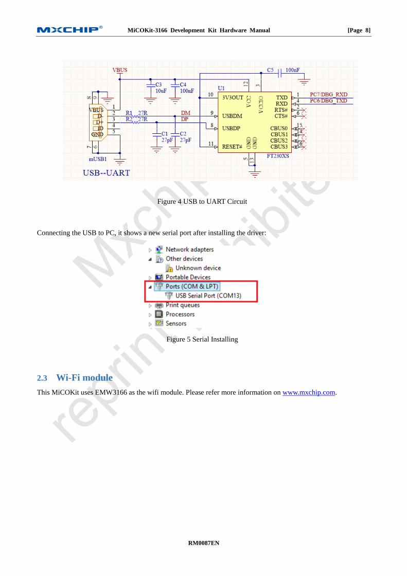
USB to UART 2.2
The part USB to UART with FT230X on MiCOKit board is applied for debugging.
The main function:
Handshake signal, modem connector signal, hardware and Xon/Xoff data flow control;
UART: 7/8 Bit data bits, 1/2 stop bits, odd/even parity;
Rate: 300=>3M(TTL), 512Byte buffer;
I/O voltage: 3.3V-5V;
Compatible with USB 2.0;
Driver: Windows 8 32/64-bit, Windows 7 32/64-bit, Windows Vista/Vista 64-bit, Windows XP/XP 64-bit,
Server 2003, XP and Server 2008, Windows XP Embedded, Windows CE 4.2, 5.0 and 6.0, Mac OS-X, Linux
3.2 and greater, Android and so on.
Packaged as SSOP16 and QFN16 with lead free.
The circuit for this part:
MiCOKit-3166 Development Kit Hardware Manual [Page 8]
RM0087EN
Figure 4 USB to UART Circuit
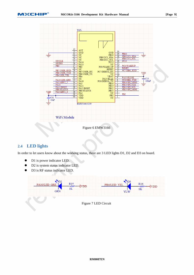
Connecting the USB to PC, it shows a new serial port after installing the driver:
Figure 5 Serial Installing
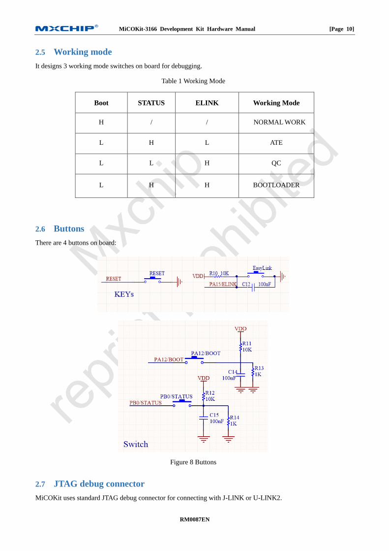
Wi-Fi module 2.3
This MiCOKit uses EMW3166 as the wifi module. Please refer more information on www.mxchip.com.
MiCOKit-3166 Development Kit Hardware Manual [Page 9]
RM0087EN
Figure 6 EMW3166
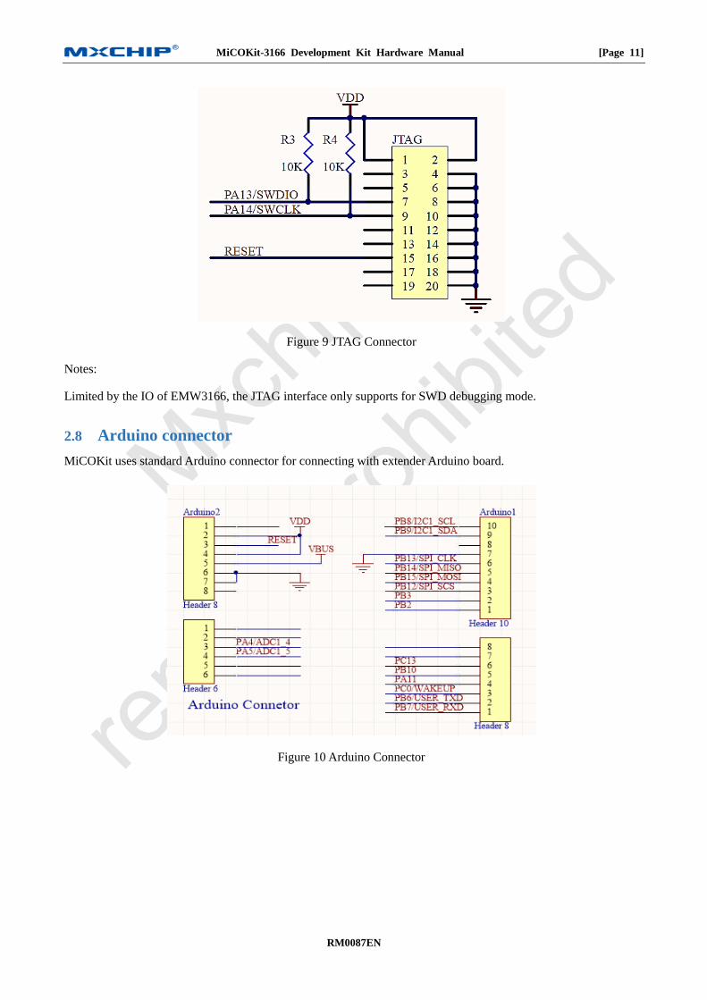
LED lights 2.4
In order to let users know about the working status, there are 3 LED lights D1, D2 and D3 on board.
D1 is power indicator LED.
D2 is system status indicator LED.
D3 is RF status indicator LED.
Figure 7 LED Circuit
MiCOKit-3166 Development Kit Hardware Manual [Page 10]
RM0087EN
Working mode 2.5
It designs 3 working mode switches on board for debugging.
Table 1 Working Mode
Boot STATUS ELINK Working Mode
H / / NORMAL WORK
L H L ATE
L L H QC
L H H BOOTLOADER
Buttons 2.6
There are 4 buttons on board:
Figure 8 Buttons
JTAG debug connector 2.7
MiCOKit uses standard JTAG debug connector for connecting with J-LINK or U-LINK2.
MiCOKit-3166 Development Kit Hardware Manual [Page 11]
RM0087EN
Figure 9 JTAG Connector
Notes:
Limited by the IO of EMW3166, the JTAG interface only supports for SWD debugging mode.
Arduino connector 2.8
MiCOKit uses standard Arduino connector for connecting with extender Arduino board.
Figure 10 Arduino Connector
MiCOKit-3166 Development Kit Hardware Manual [Page 12]
RM0087EN
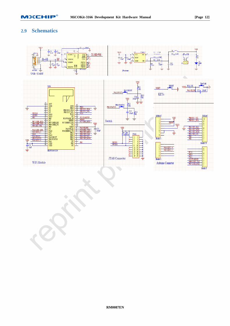
Schematics 2.9
MiCOKit-3166 Development Kit Hardware Manual [Page 13]
RM0087EN
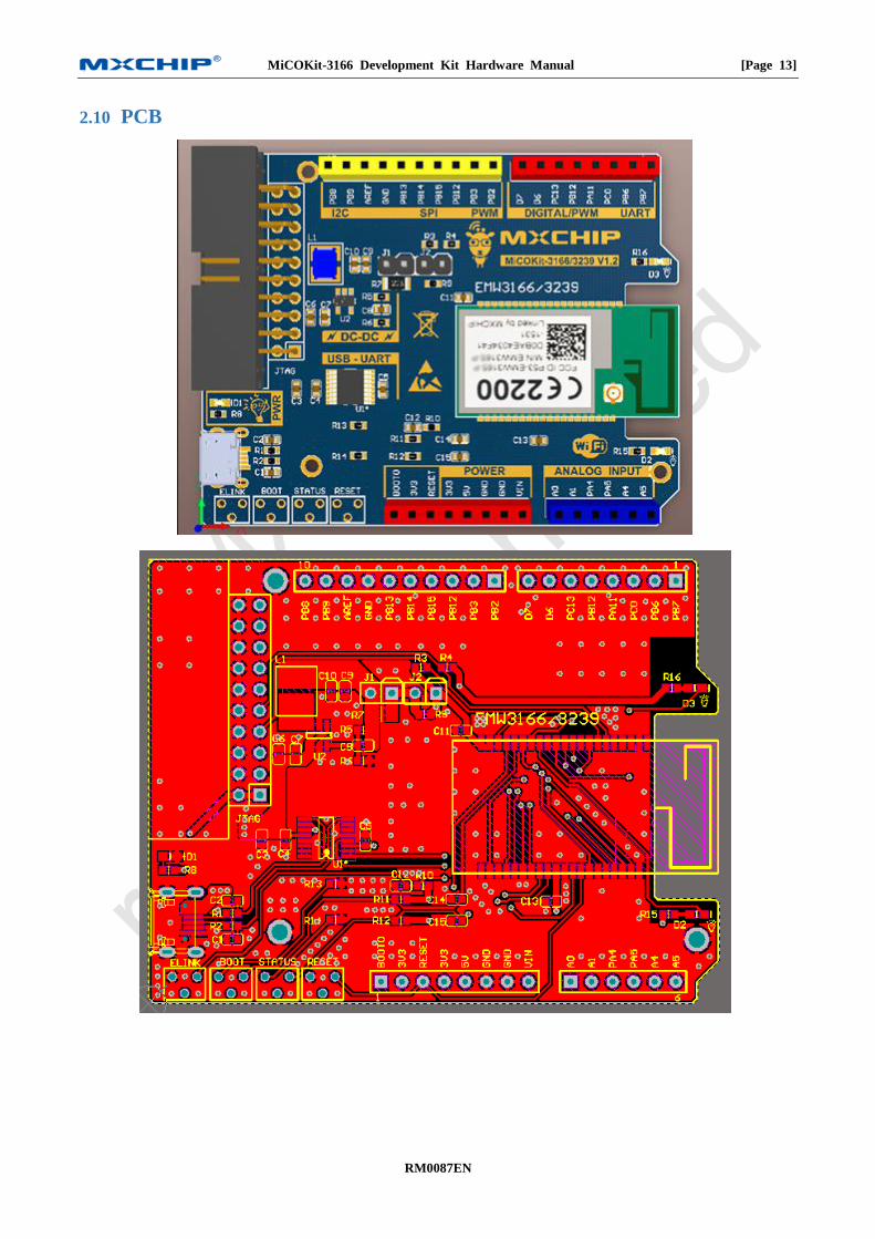
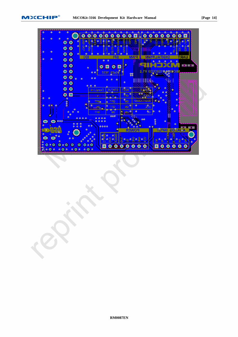
PCB 2.10
MiCOKit-3166 Development Kit Hardware Manual [Page 14]
RM0087EN
MiCOKit-3166 Development Kit Hardware Manual [Page 15]
RM0087EN
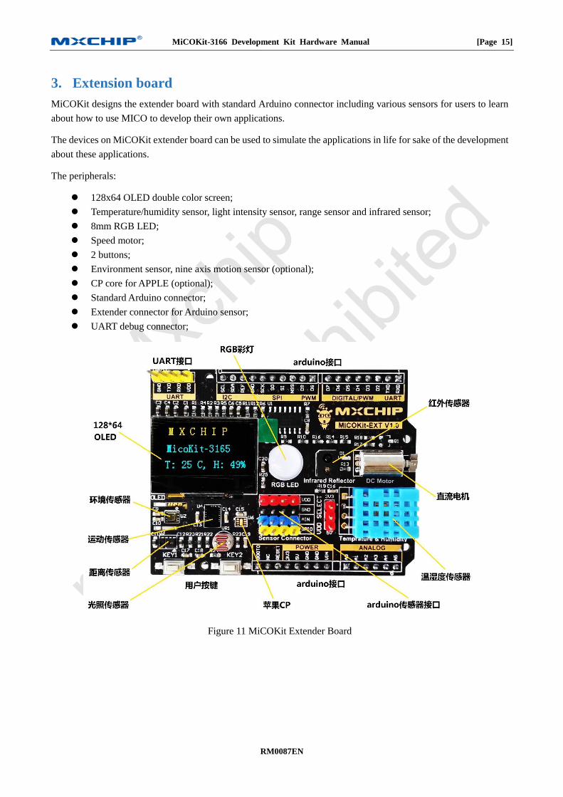
3. Extension board
MiCOKit designs the extender board with standard Arduino connector including various sensors for users to learn
about how to use MICO to develop their own applications.
The devices on MiCOKit extender board can be used to simulate the applications in life for sake of the development
about these applications.
The peripherals:
128x64 OLED double color screen;
Temperature/humidity sensor, light intensity sensor, range sensor and infrared sensor;
8mm RGB LED;
Speed motor;
2 buttons;
Environment sensor, nine axis motion sensor (optional);
CP core for APPLE (optional);
Standard Arduino connector;
Extender connector for Arduino sensor;
UART debug connector;
Figure 11 MiCOKit Extender Board
MiCOKit-3166 Development Kit Hardware Manual [Page 16]
RM0087EN
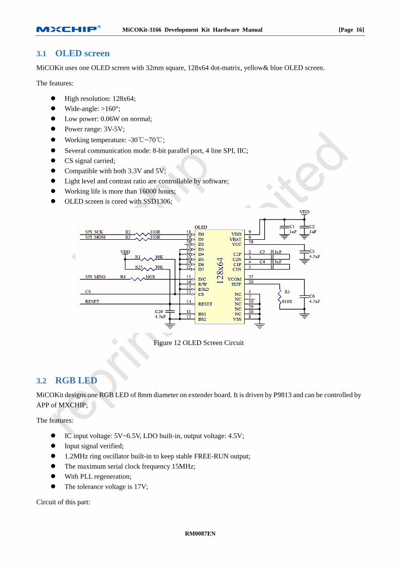
OLED screen 3.1
MiCOKit uses one OLED screen with 32mm square, 128x64 dot-matrix, yellow& blue OLED screen.
The features:
High resolution: 128x64;
Wide-angle: >160°;
Low power: 0.06W on normal;
Power range: 3V-5V;
Working temperature: -30℃~70℃;
Several communication mode: 8-bit parallel port, 4 line SPI, IIC;
CS signal carried;
Compatible with both 3.3V and 5V;
Light level and contrast ratio are controllable by software;
Working life is more than 16000 hours;
OLED screen is cored with SSD1306;
Figure 12 OLED Screen Circuit
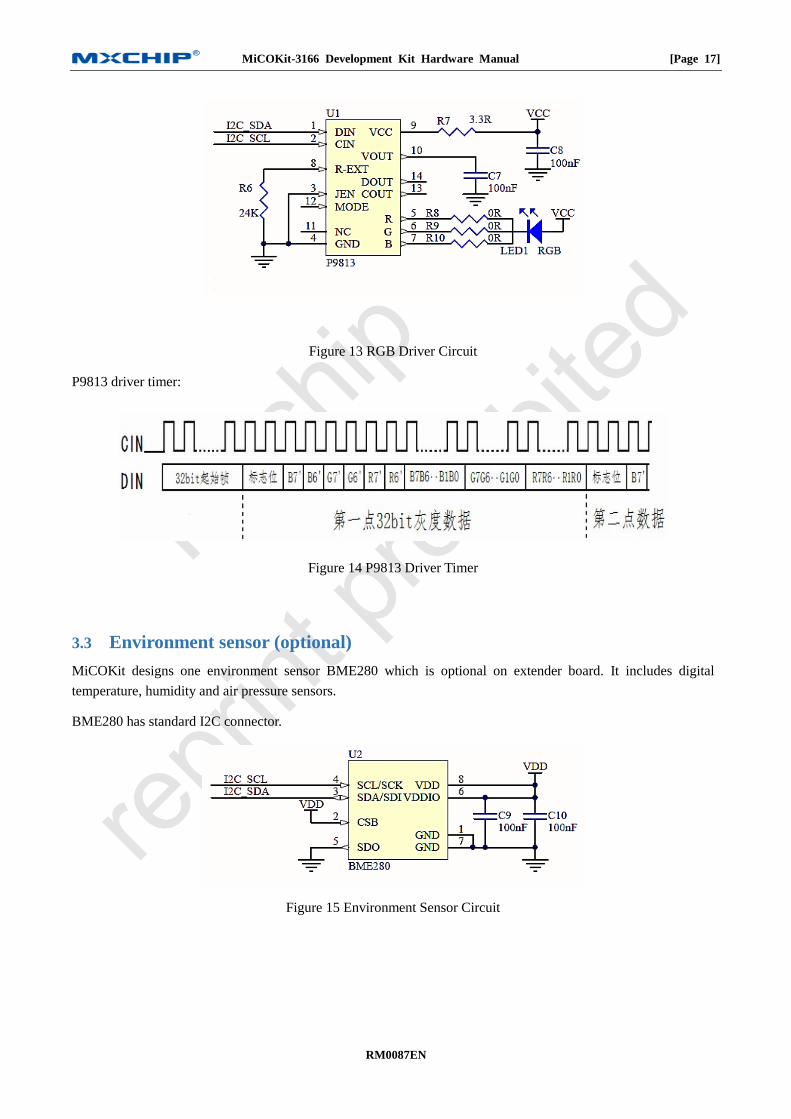
RGB LED 3.2
MiCOKit designs one RGB LED of 8mm diameter on extender board. It is driven by P9813 and can be controlled by
APP of MXCHIP;
The features:
IC input voltage: 5V~6.5V, LDO built-in, output voltage: 4.5V;
Input signal verified;
1.2MHz ring oscillator built-in to keep stable FREE-RUN output;
The maximum serial clock frequency 15MHz;
With PLL regeneration;
The tolerance voltage is 17V;
Circuit of this part:
MiCOKit-3166 Development Kit Hardware Manual [Page 17]
RM0087EN
Figure 13 RGB Driver Circuit
P9813 driver timer:
Figure 14 P9813 Driver Timer
Environment sensor (optional) 3.3
MiCOKit designs one environment sensor BME280 which is optional on extender board. It includes digital
temperature, humidity and air pressure sensors.
BME280 has standard I2C connector.
Figure 15 Environment Sensor Circuit
MiCOKit-3166 Development Kit Hardware Manual [Page 18]
RM0087EN
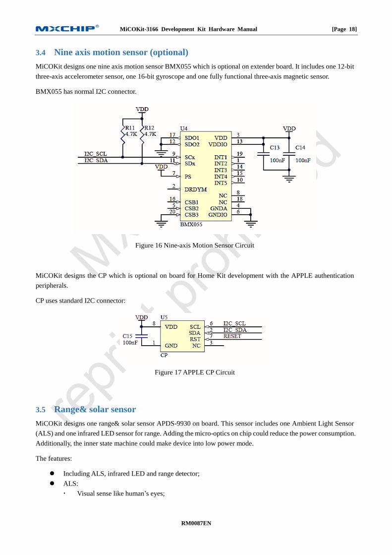
Nine axis motion sensor (optional) 3.4
MiCOKit designs one nine axis motion sensor BMX055 which is optional on extender board. It includes one 12-bit
three-axis accelerometer sensor, one 16-bit gyroscope and one fully functional three-axis magnetic sensor.
BMX055 has normal I2C connector.
Figure 16 Nine-axis Motion Sensor Circuit
MiCOKit designs the CP which is optional on board for Home Kit development with the APPLE authentication
peripherals.
CP uses standard I2C connector:
Figure 17 APPLE CP Circuit
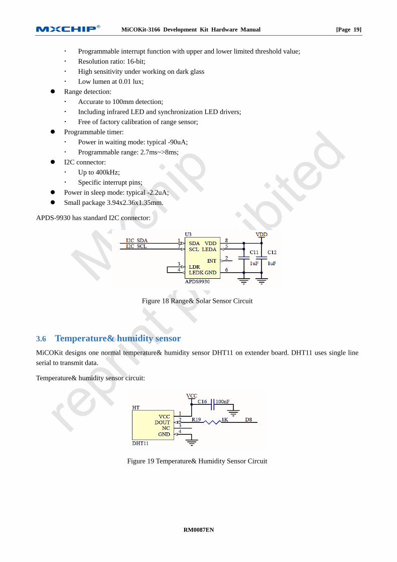
Range& solar sensor 3.5
MiCOKit designs one range& solar sensor APDS-9930 on board. This sensor includes one Ambient Light Sensor
(ALS) and one infrared LED sensor for range. Adding the micro-optics on chip could reduce the power consumption.
Additionally, the inner state machine could make device into low power mode.
The features:
Including ALS, infrared LED and range detector;
ALS:
Visual sense like human’s eyes;
MiCOKit-3166 Development Kit Hardware Manual [Page 19]
RM0087EN
Programmable interrupt function with upper and lower limited threshold value;
Resolution ratio: 16-bit;
High sensitivity under working on dark glass
Low lumen at 0.01 lux;
Range detection:
Accurate to 100mm detection;
Including infrared LED and synchronization LED drivers;
Free of factory calibration of range sensor;
Programmable timer:
Power in waiting mode: typical -90uA;
Programmable range: 2.7ms~>8ms;
I2C connector:
Up to 400kHz;
Specific interrupt pins;
Power in sleep mode: typical -2.2uA;
Small package 3.94x2.36x1.35mm.
APDS-9930 has standard I2C connector:
Figure 18 Range& Solar Sensor Circuit
Temperature& humidity sensor 3.6
MiCOKit designs one normal temperature& humidity sensor DHT11 on extender board. DHT11 uses single line
serial to transmit data.
Temperature& humidity sensor circuit:
Figure 19 Temperature& Humidity Sensor Circuit
MiCOKit-3166 Development Kit Hardware Manual [Page 20]
RM0087EN
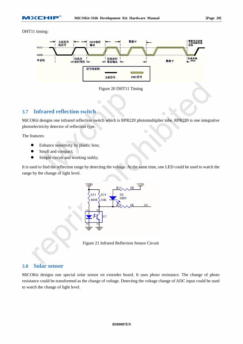
DHT11 timing:
Figure 20 DHT11 Timing
Infrared reflection switch 3.7
MiCOKit designs one infrared reflection switch which is RPR220 photomultiplier tube. RPR220 is one integrative
photoelectricity detector of reflection type.
The features:
Enhance sensitivity by plastic lens;
Small and compact;
Simple circuit and working stably;
It is used to find the reflection range by detecting the voltage. At the same time, one LED could be used to watch the
range by the change of light level.
Figure 21 Infrared Reflection Sensor Circuit
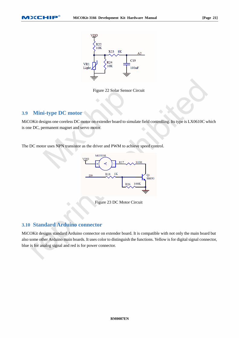
Solar sensor 3.8
MiCOKit designs one special solar sensor on extender board. It uses photo resistance. The change of photo
resistance could be transformed as the change of voltage. Detecting the voltage change of ADC input could be used
to watch the change of light level.
MiCOKit-3166 Development Kit Hardware Manual [Page 21]
RM0087EN
Figure 22 Solar Sensor Circuit
Mini-type DC motor 3.9
MiCOKit designs one coreless DC motor on extender board to simulate field controlling. Its type is LX0610C which
is one DC, permanent magnet and servo motor.
The DC motor uses NPN transistor as the driver and PWM to achieve speed control.
Figure 23 DC Motor Circuit
Standard Arduino connector 3.10
MiCOKit designs standard Arduino connector on extender board. It is compatible with not only the main board but
also some other Arduino main boards. It uses color to distinguish the functions. Yellow is for digital signal connector,
blue is for analog signal and red is for power connector.
MiCOKit-3166 Development Kit Hardware Manual [Page 22]
RM0087EN
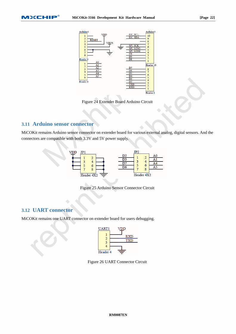
Figure 24 Extender Board Arduino Circuit
Arduino sensor connector 3.11
MiCOKit remains Arduino sensor connector on extender board for various external analog, digital sensors. And the
connectors are compatible with both 3.3V and 5V power supply.
Figure 25 Arduino Sensor Connector Circuit
UART connector 3.12
MiCOKit remains one UART connector on extender board for users debugging.
Figure 26 UART Connector Circuit
MiCOKit-3166 Development Kit Hardware Manual [Page 23]
RM0087EN
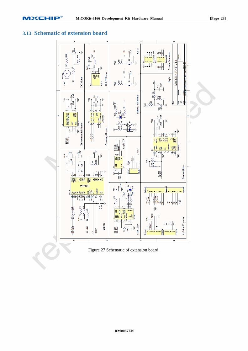
Schematic of extension board 3.13
Figure 27 Schematic of extension board