microcamp atmega8 activity kit manua
DESCRIPTION
Microcamp activity kit from robotshop.comTRANSCRIPT

MicroCamp : ATmega8 Activity Kit Manual 1
MicroCampATmega8 Activity Kit
manual
www.inex.co.thwww.inexglobal.com

2MicroCamp : ATmega8 Activity Kit Manual
Content
!" # $
% &'("
) # $ %
* &'!
+ ," ' *
!"#$
%& '
"
( $
! ) * '+
!(*
!, *
!! ) *
' " -

MicroCamp : ATmega8 Activity Kit Manual 3
Chapter 1MicroCamp Activity kit
hardwareMicroCamp is a set of Microcontroller Activity kit for learning about Micro-
controller operation via Robotic activities with C language programming. You will learn
about simple operation of microcontroller and how to interface with external
components in real word applications.
This activity kit includes Microcontroller board (will call “MicroCamp board”),
Swtich module, Infrared Reflector module, DC motor gearboxes and many other
mechnical parts for building a programmable robot.
Figure 1-1 shows the layout of MicroCamp main controller board.
SW2 (PD3)
SW1 (PD2)
Piezo speaker (PD4)
Motor A output
Motor B output
38kHz InfraredReceiver moduleconnector
POWER switch
Input-Outputconnector
P0 = PC0/ADC0P1 = PC1/ADC1P2 = PC2/ADC2P3 = PC3/ADC3P4 = PC4/ADC4
I n - S y s t e mProgrammingc o n n e c t o r(ISP)
Battery Terminal (6Vdc max.)RESET switch
POWER indicator
LED1 indicator (PC5)
LED2 indicator (PD1)
Serial data communication port
Motor A indicator
Motor B indicator
ATmega8microcontroller

4MicroCamp : ATmega8 Activity Kit Manual
1.1 Hardware of MicroCamp Activity kit1.1.1 MicroCamp controller board
The main microcontroller is the 8-bit AVR microcontroller from Atmel; ATmega8.
It has many features of modern microcontroller such as the 10-bit Analog to Digial
Converter module (ADC), Flash program memory 8KB with 10,000 times erase-write cycles,
Data EEPROM 512 bytes and RAM 512 bytes too.
Main clock frequency 16MHz from Xtal.
5-channels Programmable 3-pin Input/Output port. User can programmable all
port pins for usages as a Digial Input port, Digital Output port and an Analog input port.
The 3-pins are Supply voltage (normally is +5V), Signal or Data and Ground respectively.
Reserve a port for connecting 38kHz Infrared Receiver module. This port will
be assigned to share with Serial Receiving signal (RxD) to external serial data
communication device.
Piezo speaker for sound beeps
2 Push-button switches
RESET switch
2 LED indicators, active when logic is “High”
2-channels of DC motor drivers. They drive 4.5 to 6V 600mA DC motor with LED
indicators
Supply voltage of +4.8 to +6V from 4 of AA size batteries. Contain in battery
holder at the back of controller board.
On-board switching regulator circuit to maintain the +5V supply voltage when
motors function and consume more current.
1.1.2 PX-400 The serial port interface In-System Programmer boxThis programmer is used for programming the code into flash memory within the
AVR microcontroller. It can work a wide variety of AVR microcontrollers.
Its features are :
Connection with computer serial port via RS-232. If the computer has
only USB port, a USB to Serial port converter can be used. The UCON-232S is highly
recommended for this purpose.
Program the AVR microcontroller via ISP cable. Supports Read, Write,
Erase and Data protection functions.

MicroCamp : ATmega8 Activity Kit Manual 5
Require +5V supply voltsge from target microcontroller board.
Operate with AVR Prog software. This software is included in the AVR
Studio and can be found in the tools menu and works with the Avr-OspII software as well.
Model Numbers of microcontroller supported in AVR Prog
AT90S1200, AT90S2313, AT90S2323, AT90S2343, AT90S4433 , AT90S8515 , AT90S8535 ,
ATmega128 , ATmega16 , ATmega161 , ATmega162 , ATmega163 , ATmega164P ,ATmega165 , ATmega168 , ATmega32 , ATmega64 , ATmega8 , ATmega8515 ,ATmega8535 ,
ATtiny12 , ATtiny13 , ATtiny15L , ATtiny2313, ATtiny26
Model Numbers of microcontroller supported in Avr-OSP II
AT90CAN128, AT90CAN32, AT90CAN64,
AT90PWM2, AT90PWM3,
AT90S1200, AT90S2313, AT90S2323, AT90S2343, AT90S4414, AT90S4433, AT90S4434,AT90S8515, AT90S8515comp, AT90S8535, AT90S8535comp,
ATmega103, ATmega103comp, ATmega128, ATmega1280, ATmega1281,
ATmega16, ATmega161, ATmega161comp, ATmega162, ATmega163, ATmega165,ATmega168, ATmega169,
ATmega2560, ATmega2561,
ATmega32, ATmega323, ATmega325, ATmega3250, ATmega329, ATmega3290,
ATmega406, ATmega48,
ATmega64, ATmega640, ATmega644, ATmega645, ATmega6450, ATmega649,ATmega6490,
ATmega8, ATmega8515, ATmega8535, ATmega88,
ATtiny11, ATtiny12, ATtiny13, ATtiny15,
ATtiny22, ATtiny2313,ATtiny24, ATtiny25, ATtiny26, ATtiny261, ATtiny28,
ATtiny44, ATtiny45, ATtiny461,
ATtiny84, ATtiny85, ATtiny861
!"#$% &

6MicroCamp : ATmega8 Activity Kit Manual
'
µ
!
"#
!
!
!
"#
!$%
$%
$
$
$
$
!$!
$
$
$"
$&
$"&

MicroCamp : ATmega8 Activity Kit Manual 7
1.2 MicroCamp controller board circuitdescription
The heart of this controller board is ATmega8 microcontroller. It runs on a 16MHz
clock from crytal which is connected at PB6 and PB7 pin.
For PC0 to PC4 port is defined as the new name to P0 to P4. It is labeled on the
circuit board for easy reference. All ports can programmable to analog or digital input/
output. Analog signal from these port would pass through the Analog to Digital Converter
module within ATmega8. The resolution conversion is at 10-bit.
PB3, PB4 and PB5 are In-System Programming port. They are connected to ISP
connector for connect with the external ISP programmer box.
PC6/RESET pin is connected with the RESET swtich for resetting to restart the
microcontroller operation from user.
PD0/RxD pin is the serial receiver pin. It is shared with IRM connector for 38kHz
Infrared Receiver Module and 5-pin of Serial data communication port.
PD1/TxD pin is the serial transmit pin. It is shared to drive the LED5 (IND2 label) and
TxD pin of 5-pin of Serial data communication port. For LED4 or IND1 is direct connected
to PC5 of ATmega8 microcontroller with current-limit resistor.
The MicroCamp board is equipped with 2 Push-button switches. They are
connected to PD2 and PD3 and connected 4.7kΩ resistor pull-up for setting the logic
level to “High” in a normal operation and changing to logic “Low” or “0” when switch
is pressed.
PD4 pin is connected with a Piezo speaker via coupling capacitor 10µF.
The MicroCamp controller board includes the DC motor driver circuit. It has 2
outputs. The driver IC is L293D H-Bridge driver. One DC motor driver circuit requires 3
signal pins to control :
A and B input for applying the signal to select the spin direction of motor.
E control pin is used for enble and stop operation of driver circuit. In
addition, the user can control the motor speed with apply PWM signal to this pin. If the
width of PWM is wide, it means the high level of voltage sent to motor output.
At the output of L293D, bi-color LED is connected to indicate the voltage pole at
the output. Green color indicates forward. Red color indicates backward.
The Power suppy circuit of this board is switching type circuit. TL499A is set to step-
up +5V switching regulator for supply voltage to all microcontroller circuit except for the
motor driver. With this circuit, it helps microcontoller voltage supply to be more stabilized.
Although DC motors require more power during operation but the supply voltage of
microcontroller is still fixed at +5V.

8MicroCamp : ATmega8 Activity Kit Manual
1.3 MicroCamp activity kit’s cable assignmentThe MicroCamp activity kit includes some signal cables for the interfacing
between the controller board, sensor module and the computer. They includes the ISP
cable for programming the microcontroller, PCB3AA-8 cables for interconnection to the
sensor module and a Serial port cable for interfacing with the computer.
1.3.1 ISP cableIt is 10-wires ribbon cable. Both ends are attached to the female 10-pin IDC header.
It is used for interfacing between ISP programmer box and Microcontroller board at ISP
connector. This ISP cable’s assignment is compatible with Atmel’s programming tools
standard. The wire assignment can show with the diagram below.
1.3.2 PCB3AA-8 cableThis is an INEX standard cable, 3-wires combined with 2mm. The PCB connector is
at each end. 8 inches (20cm.) in length. Used for connecting between microcontroller
board and all the sensor modules in MicroCamp kit. The wire assignment is shown in the
diagram below.
1.3.3 CX-4 serial port cableThis is used to connect between the computer’s RS-232 serial port and the target
or external device such as a Microcontroller board, eg. The MicroCamp controller board.
The connector’s end uses a DB-9 female connector, and the other end uses a Modular
plug RJ-11 6P4C (6-pins form and 4-contacts) Its Length is 1.5 meters. In the kit, this cable is
used to connect between RS-232 serial port and PX-400 programmer box. The wire
assignment is shown in the diagram below.

MicroCamp : ATmega8 Activity Kit Manual 9
1.4 ATmega8 microcontroller OverviewThe ATmega8 is a low-power CMOS 8-bit microcontroller based on the AVR
enhanced RISC architecture. By executing powerful instructions in a single clock cycle,
the ATmega8 achieves throughputs approaching 1 MIPS per MHz allowing the system
designer to optimize power consumption versus processing speed.
The ATmega8 which use in MicroCamp board is 28-pin DIP package. The pin
assignment shows in the figure 1-4.
1.4.1 ATmega8 features It is a low-power 8-bit microcontroller based on the AVR RISC architecture.
8K bytes of In-System Programmable Flash with Read-While-Write capabilities 10,000
times erase cycle, 512 bytes of EEPROMwith 100,000 times erase cycle, 1K byte of SRAM
and 32 general purpose working registers.
23 General I/O lines. manage to 3 groups
1. Port B (PB0 to PB7) : Use 2 pin (PB6 and PB7) for connect crystal for clock
generator circuit. PB2 to PB5 normally are reserved for In-system porogramming port.
Thus PB0 and PB1 free for general purpose application.
2. Port C (PC0 to PC6 : 7 pins) PC0 to PC5 are analog input pins. PC6 normally
use for RESET pin.
3. Port D (PD0 to PD7 : 8 pins) This port can support general purpose
application.
#()*
#()

10MicroCamp : ATmega8 Activity Kit Manual
Two 8-bit Timer/Counters with Separate Prescaler, one Compare Mode
16-bit Timer/Counter with Separate Prescaler, Compare Mode, and Capture Mode
Real Time Counter with Separate Oscillator
Three PWM Channels
6-channel ADC, 10-bit Accuracy
Byte-oriented Two-wire Serial Interface
Programmable Serial USART
Master/Slave SPI Serial Interface
Programmable Watchdog Timer with Separate On-chip Oscillator
On-chip Analog Comparator
Power-on Reset and Programmable Brown-out Detection
Internal Calibrated RC Oscillator
External and Internal Interrupt Sources
5 Sleep Modes: Idle, ADC Noise Reduction, Power-save, Power-down, and Standby
Operating Voltage 4.5 - 5.5V
Speed Grades 0 to 16 MHz
1.4.2 Block diagram of ATmega8Figure 1-5 shows the ATmega8 microcontroller block diagram. The AVR core
combines a risc instruction set with 32 general purpose working registers. The ATmega8
provides the following features: 8K bytes of In-System Programmable Flash with Read-
While-Write capabilities, 512 bytes of EEPROM, 1K byte of SRAM, 23 general purpose I/O
lines, 32 general purpose working registers, three flexible Timer/Counters with compare
modes, internal and external interrupts, a serial programmable USART, a byte oriented
Two-wire Serial Interface, a 6-channel ADC with 10-bit accuracy, a programmable
Watchdog Timer with Internal Oscillator, an SPI serial port, and five software selectable
power saving modes. The Idle mode stops the CPU while allowing the SRAM, Timer/
Counters, SPI port, and interrupt system to continue functioning.
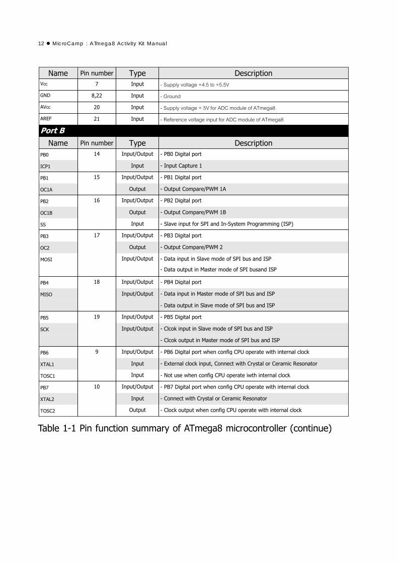
1.4.3 ATmega8 pin functionTable 1-1 is summary information about ATmega8 pin function.

MicroCamp : ATmega8 Activity Kit Manual 11
!
"
#
$%&
''%()
#
$&
*+&
(
#(
&
(
,-*
.-/
0-/
'
!
"
+#(),-.
12MicroCamp : ATmega8 Activity Kit Manual
( " "#() / 0
!
"# !
$"%& !
$"%& "# !
'( "%"%& )$% * +$, "$%-
$% * +$, "$%-
)
./ "
$
$ 01
$ 0.
"# , //2 3
$ 0
"# !
!
./ " *+%/$ 4 * + "%"%&
5 *+%/$ 4 * + "%"%&
./ " *+%/$ 4 * + "%"%&
$"%& *+%/$ 4 * + "%"%&
./ "
./ "
./ "
./ "
./ "

MicroCamp : ATmega8 Activity Kit Manual 13
( " "#() /" 0
1"/% %+"
1"/ %+"
1"/ %+"
1"/ %+"
1"/ %+"
1"/ %+"
1"/ %+"
"$"%& 0! %
'( "
41-6%#/
/ "
41-6
'( " %+"
/ "
'( " %+"
/ "
41-6( "%"%&
6'( "
/ "
6'( "
/ "
/ "
1"/% %+"
$
$
$
$
$
$
$
/ "
/ "
" 0! %

14MicroCamp : ATmega8 Activity Kit Manual
MicroCamp : ATmega8 Activity Kit Manual 15
Programming development in MicriCamp Activity kit is C language. The software
tools that are installed for programming are the following :
1. AVR Studio : This software tool is developed by Atmel Corporation. AVR Studio
is a Development Tool for the AVR microcontrollers. AVR Studio enables the user to fully
control execution of programs on the AVR In-Circuit Emulator or on the built-in AVR
Instruction Set Simulator. AVR Studio supports source level execution of Assembly
programs assembled with the Atmel Corporation’s AVR Assembler and C programs
compiled with WinAVR open-source C Compiler. AVR Studio runs under Microsoft
Windows95 and Microsoft Windows NT. Now Windows XP SP2 is recommended. Free
download this software at www.atmel.com.
2. WinAVR : WinAVR is a set of tools for the C compiler, these tools include avrgcc
(the command line compiler), avr-libc (the compiler library that is essential for avrgcc),
avr-as (the assembler), avrdude (the programming interface), avarice (JTAG ICE
interface), avr-gdb (the de-bugger), programmers notepad (editor) and a few others.
These tools are all compiled for Microsoft Windows and put together with a nice installer
program. Free download of the updated version is located at : http://sourceforge.net/projects/winavr/.
For the MicroCamp Activity kit, C programming will be with WinAVR V20050214.
User will need to install AVR Studio first and WinAVR after which. AVR Studio’s mechanism
integrates automatically with WINAVR. With this feature, it assist the user in the
development of C language and programming on AVR Studio which is much easier
and more powerful compared to WinAVR. The compiled file is a HEX file in which case,
the user has to download it into the program memory of the AVR microcontroller Board.
3. Library : These are the support files which allows the user to develop their C
language program more comfortably. An example is the Port control library for controlling
both Digital and Analog Input/Output, Motor control instructions, etc.
4. Programmer software : This software is used to download the compiled .HEX file
to the AVR Microcontroller. Included in this kit is the AVRProg. It is Atmel’s software and
an add-in feature in AVR Studio. AVR Prog software works with the PX-400 Serial port In-
system programmer box. The PX-400 programmer is bundled in the MicroCamp Activity
kit.
Chapter 2Development software for
MicroCamp Activity kit

16 MicroCamp : ATmega8 Activity Kit Manual
2.1 Installation AVR StudioInstallation of AVR Studio in Windows XP:
2.1.1 Insert the MicroCamp CD-ROM and look for this file in the AVR Studio
directory; aStudio4b460.exe. Double-click this file.
2.1.2 Enter Installation Wizard. Click on the Next button to continue.
2.1.3 In the license agreement window, Select the box : I accept the terms of thelicense agreement and Click on the Next button.

MicroCamp : ATmega8 Activity Kit Manual 17
2.1.4 Choose Destination Location wondows will appear. You can change the
path by clicking on the Change button and setting the new path. After this, click on the
Next button.
2.1.5 The Driver USB Upgrade window will now appear. Click on the Next button
to pass this step.
2.1.6 In the begin installation window, click on the Install button to start installation.
2.1.7 After installation is complete, click on the Finish button to end the installation
of AVR Studio.

18 MicroCamp : ATmega8 Activity Kit Manual
2.1.8 To launch the AVR Studio program. Click on Start Programs Atmel AVR
Tools AVR Studio 4. The main window of the AVR Studio program will appear.
MicroCamp : ATmega8 Activity Kit Manual 19
2.2 Instalaltion of WinAVRPlease note that installation of WinAVR is done after the installation of AVR Studio.
Please ensure this is being done before proceeding.
Installation of WinAVR in Windows XP :
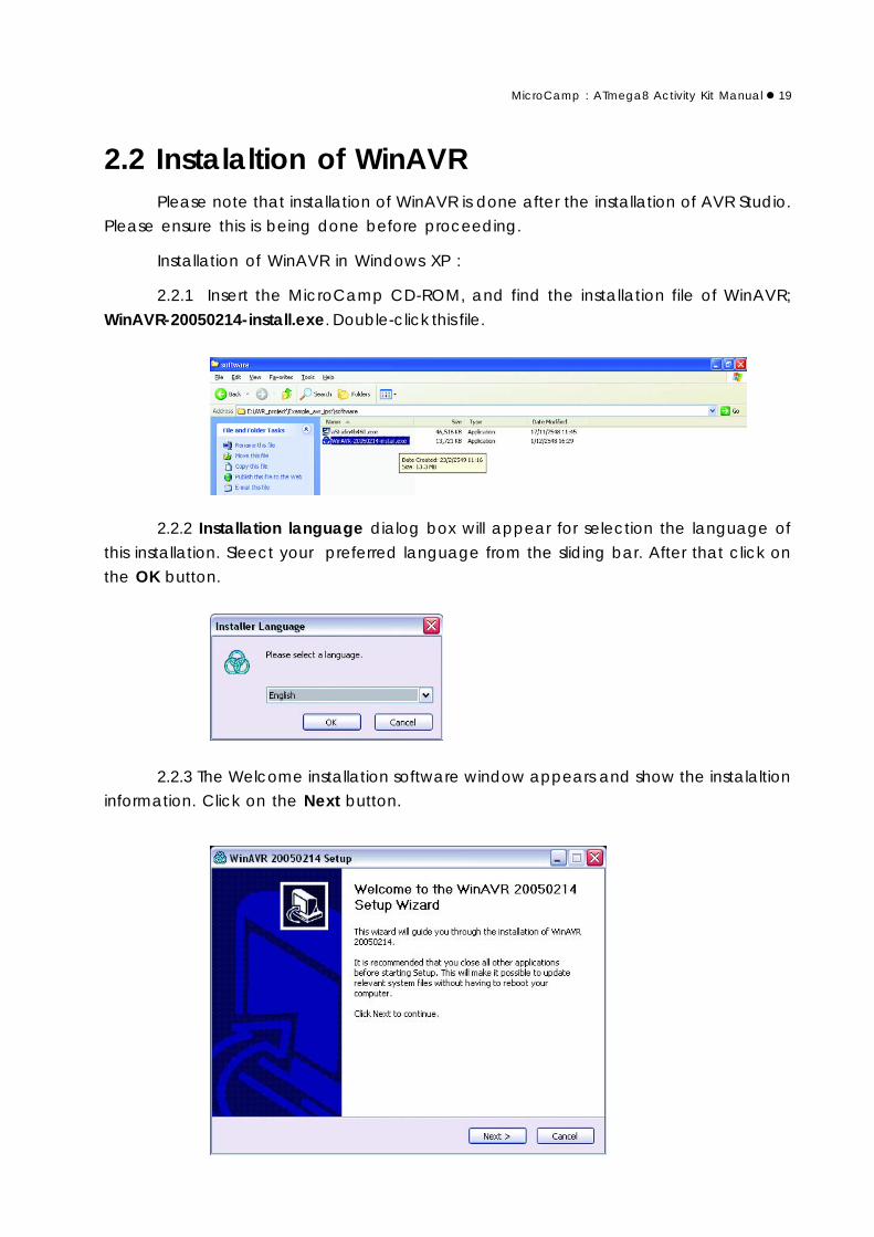
2.2.1 Insert the MicroCamp CD-ROM, and find the installation file of WinAVR;
WinAVR-20050214-install.exe. Double-click this file.
2.2.2 Installation language dialog box will appear for selection the language of
this installation. Sleect your preferred language from the sliding bar. After that click on
the OK button.
2.2.3 The Welcome installation software window appears and show the instalaltion
information. Click on the Next button.

20 MicroCamp : ATmega8 Activity Kit Manual
2.2.4 In the License agreement window, Click on the I agree button.
2.2.5 Choose Install Location window appears. User can change the path and
the folder for installation of WinAVR by clicking at the Browse button and selecting the
respective folder. The proposed folder is C:\WinAVR. After selection, click on the Nextbutton to continue to the next step.

MicroCamp : ATmega8 Activity Kit Manual 21
2.2.6 In the Choose Components window. select the components which you
want to install or follow according to the below diagram. Click on the Install button to
begin installation.
2.2.7 The installation process starts and reports the status back on the screen. The
User needs to wait until the installation is complete. Click on the Finish button to end
once its done.
2.3 Copying LibraryYou will need to copy the library file (.H file) from the MicroCamp_include folder
in the Cd-ROM. It is better to copy these files to a folder where you save your
programming codes.
During the program development of MicroCamp with AVR Studio and WinAVR,
you will need to define or set the path of all the tools to integrate with the MicroCamp_include folder. Ensure that the path of the MicroCamp_include folder is correct.
This is very important as if the path details are not clear or missing, the whole compilation
process will have errors.

22 MicroCamp : ATmega8 Activity Kit Manual

MicroCamp : ATmega8 Activity Kit Manual 23
3.1 The heart is the C compilerIn actual fact, writing of the C program for the microcontroller is not the actual
code that is sent to the microcontroller’s program memory. The real data is in the machine
code which is being compiled from the written C code and compiled with the C
Compiler software.
The steps in C programming development are as follows:
(1) Write the C programs with the text editor / Project IDE that is provided.
(2) Compile the C code into assembly Code for the microcontroller
(3) The Assembly Code will be converted into Machine Code into HEX file
format.
(4) Download this code into the program memory of the microcontroller
(5) Run the microcontroller. Go back to step 1 if you have errors.
Steps (2) and (3) will not be shown as the C Compiler will do all of these in its
background.
After installing AVR Studio and WINAVR software, the library files are required to
be copied in order to support the MicroCamp kit. The MicroCamp Library files are
contained in the MicroCamp_include folder in the CDROM that is included in this kit.
In the C programming development platform in AVR Studio, developers need to
compile it into project file format. After the codes are being compiled into HEX file using
the same name as the project filename, the file is needs to be downloaded into the
ATMEGA8 Microcontroller.
For example :
Name the project file to test_segment. After compiled, the result file is
test_segment.hex
Chapter 3C programming development
for MicroCamp kit withAVR Studio and WinAVR compiler
24MicroCamp : ATmega8 Activity Kit Manual
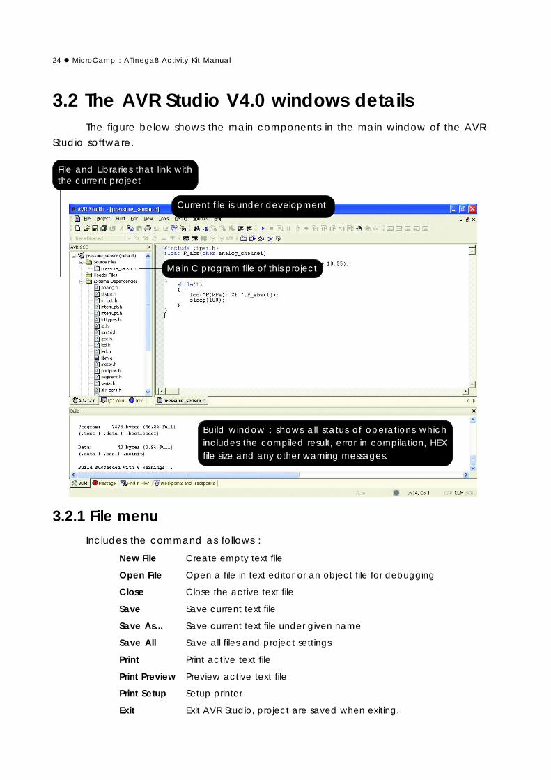
3.2 The AVR Studio V4.0 windows detailsThe figure below shows the main components in the main window of the AVR
Studio software.
File and Libraries that link withthe current project
Current file is under development
Main C program file of this project
Build window : shows all status of operations whichincludes the compiled result, error in compilation, HEXfile size and any other warning messages.
3.2.1 File menuIncludes the command as follows :
New File Create empty text file
Open File Open a file in text editor or an object file for debugging
Close Close the active text file
Save Save current text file
Save As... Save current text file under given name
Save All Save all files and project settings
Print Print active text file
Print Preview Preview active text file
Print Setup Setup printer
Exit Exit AVR Studio, project are saved when exiting.

MicroCamp : ATmega8 Activity Kit Manual 25
3.3.2 Project menuIncludes the command as follows :
Project Wizard Open the project wizard.
You must close the current project first.
New Project Open the new project dialog.
You must close the current project first.
Open Project Open a new project, either an APS project file or an object file.
Save Project Save the current project with all settings
Close Project Close the current project
Recent Projects Show a list of recent project, select one to open
Configuration Options This option is only available when the project is a code writingproject. E.g. an assembler or AVR GCC project. This com-mand open the configuration dialog for the current project.
3.2.3 Build menuIncludes the command as follows :
Build Build the current project
Rebuild All Rebuild all the modules in the project
Build and run Build, and if error free , start debugging session
Compile Compile the current source file
Clean Clean the current project
Export Makefile Save the current settings in a new make file
3.2.4 Edit menuIncludes the command as follows :
Undo Undo last editor action
Redo Redo any undo action
Cut Cut and copy selected text from editor
Copy Copy selected text from editor
Paste Paste any text from clipboard to the editor
Toggle Bookmark Toggle bookmark on/off at the selected line in the editor
Remove Bookmarks Remove all bookmarks
Find Open a find dialog to search through the current source file.
Find in Files Open a find in files dialog to search through all project files.
Next Error Locate and jump to the next build error if any
Show whitespace Toggle on/off whitespace markings
Font and color Open a font dialog to view/edit font settings in the sourceeditor

26MicroCamp : ATmega8 Activity Kit Manual
3.2.5 View menuThis menu includes the command as follows :
Toolbars Sub menu toggles toolbars on/off, access to customize-dialog.Described here
Status Bar Toggle status bar on/of (status bar is the line in the bottom of thescreen)
Disassembler Toggle on/off the disassembly window
Watch Toggle on/off the watch view
Memory Toggle on/off the memory view
Memory 2 Toggle on/off the memory view 2
Memory 3 Toggle on/off the memory view 3
Register Toggle on/off the register view
3.2.6 Tools menuThis is the hardware interfacing command menu. AVR Studio can interface many
hardware for development. For the MicroCamp kit, developers must select the AVRprog.
This is the operating software for the PX-400 Serial Port In-System Programmer box.
Developers must connect the PX-400 box to their COM port before open the
AVRprog software.
3.2.7 Debug menuThis menu have many commands that relates to the program simulation and
debugging. The MicroCamp kit does not require much usage of this feature.
3.3 Building C project file in AVR Studio3.3.1 Open the AVR Studio. If there is any project running, developers can close
by select the menu Project Close Project
3.3.2 To create the new project. Select the command at menu Project NewProject.
MicroCamp : ATmega8 Activity Kit Manual 27
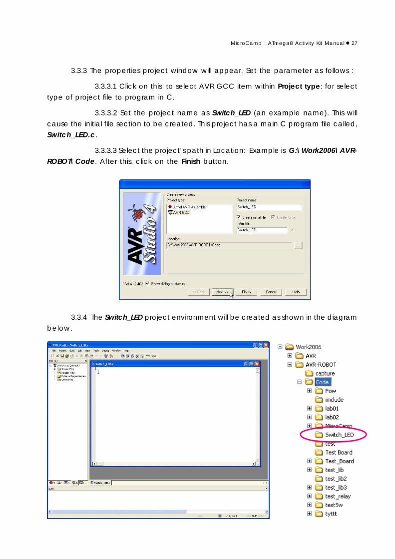
3.3.3 The properties project window will appear. Set the parameter as follows :
3.3.3.1 Click on this to select AVR GCC item within Project type: for select
type of project file to program in C.
3.3.3.2 Set the project name as Switch_LED (an example name). This will
cause the initial file section to be created. This project has a main C program file called,
Switch_LED.c.
3.3.3.3 Select the project’s path in Location: Example is G:\Work2006\AVR-ROBOT\Code. After this, click on the Finish button.
3.3.4 The Switch_LED project environment will be created as shown in the diagram
below.

28MicroCamp : ATmega8 Activity Kit Manual
The folder Switch_LED will be created in G:\Work2006\AVR-ROBOT\Code.
In the same folder the file Switch_LED.aps and main C program file Switch_LED.c will be
created.
3.3.5 Next step is to determine the microcontroller information and path of all the
library file which is being used in this project.
3.3.5.1 Select the command at Project Configuration Options
After that the window Switch_LED Project Options will appear for
setting the properties. See the left of this window. Developers will found 5 icons as :
General
Include Directories
Libraries
Memory Settings
Custom Options
3.3.5.2 At General icon, determine all data follows
Device : atmega8
Frequency: 16000000 Hz

MicroCamp : ATmega8 Activity Kit Manual 29
3.3.5.3 Click on this icon and the Include Directories for determining the
path of library file. Find and select the library file and click on the Add button. For example
is C:\AVR_ROBOT\include. After determining the path, you will found the list for selection.
3.3.5.4 Select the icon Libraries to links to all the libraries with the main file.
3.3.5.5 At the boxs , Available Link Objects:, click to select the item libm.aand click the Right Arrow button to copy the item libm.a which appears at the Link with
These Objects window. Click the OK button to finish.
30MicroCamp : ATmega8 Activity Kit Manual
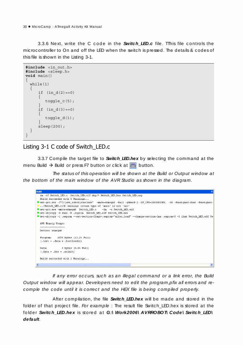
3.3.6 Next, write the C code in the Switch_LED.c file. TThis file controls the
microcontroller to On and off the LED when the switch is pressed. The details & codes of
this file is shown in the Listing 3-1.
3.3.7 Compile the target file to Switch_LED.hex by selecting the command at the
menu Build Build or press F7 button or click at button.
The status of this operation will be shown at the Build or Output window at
the bottom of the main window of the AVR Studio as shown in the diagram.
#include <in_out.h>#include <sleep.h>void main()while(1)
if (in_d(2)==0)
toggle_c(5);if (in_d(3)==0)
toggle_d(1);sleep(200);
If any error occurs, such as an illegal command or a link error, the Build
Output window will appear. Developers need to edit the program,pfix all errors and re-
comple the code until it is correct and the HEX file is being compiled properly.
After compilation, the file Switch_LED.hex will be made and stored in the
folder of that project file. For example : The result file Switch_LED.hex is stored at the
folder Switch_LED.hex is stored at G:\Work2006\AVRROBOT\Code\Switch_LED\default.

MicroCamp : ATmega8 Activity Kit Manual 31
3.4 How to develop the previously project fileDevelopers can open the previously project file for editing or improvement. Enter
to menu Project Open Project and select the path that store the target project file.
The project file is saved as .aps file
Example : If would like to open the Switch_LED project file, select to Project Open Project and access to the path or folder which contains the Switch_LED.aps file.
Open this file for editing. Developers can save with the same name or different.
3.5 Downloading and Testing the programThe next step after compiling the project file is to download the HEX file to
MicroCamp controlelr board. In this example the result file is saved as Switch_LED.hex.
The step of downloading and testing are as follows :
3.5.1 Turn on the POWER switch. The green LED at ON labeled is on.
3.5.2 Connect the download cable (ISP cable) from the PX-400 programmer box
to the In-System Prog. (ISP) connector on MicroCamp controller board.
! " #$ !
%% " % !
Connect to RS-232 serial port directly
Connect to USB port
UCON-232/UCON-232S USB to Serial port converterIf computer has not RS-232 serialport, must use USB to Serial portconverter.
MicroCampcontroller board

32MicroCamp : ATmega8 Activity Kit Manual
3.5.3 Switch to AVR Studio program, select the command at menu Tool AVRProg...
3.5.4 The AVRprog window will not appear.
3.5.5 At the AVRprog window, click on the Browse button to find the path of
Switch_LED.hex file for selection the HEX file require to download.
For novice users, it is adviced NOT to enterthe advance button of this window asthere are many advanced configurationwhich requires more experience foradjusting and changing.
If any setting are incorrect, ATMEGA8 willnot be successfully programmed via ISP.
3.5.6 Click at the Program button in the Flash command. The Switch_LED.hex filewill now be downloaded into the ATmega8 microcontroller in the MicorCamp controller
board.
3.5.7 When the download is finished, the program will run automatic. Press the
button swtich SW1 and SW2 on MicroCamp controller board. Observe the LED operation.
The LED will turn on and off when the switch is pressed and blink if the
switch is released..
MicroCamp : ATmega8 Activity Kit Manual 33
In C, a function is equivalent to a subroutine , or a procedure. A function pro-
vides a convenient way to encapsulate some computation, which can then be used
without worrying about its implementation. With properly designed functions, it is pos-
sible to ignore how a job is done; knowing what is done is sufficient. C makes the sue of
functions easy, convinient and efficient; you will often see a short function defined and
called only once, just because it clarifies some piece of code.
All C programs must have a ‘main’ function that contains the code which will be
run first when the program executes. Other sub C programs functions can be linked to
this main function. Therefore function capability is a vital component in C programming.
4.1 Function declarationIt has general format :
return_type function_name(parameter1, parameter2, ...)
command_list 1;........................................command_list n;
thus ;
function_name is the name of function
return_type is the type of the data resulting from each function. Within
this function, the command return(value) is used for sending the result data. The
target variable that the return value will be applied on must be the same as each other
to avoid any variable mismatch. Any function without a return value, void parameter
at the return_type must be.
parameter is a part of data or variable that relate with function. Some
functions require many parameters, while some functions have none. If no parameters
are required, a void can be declared. Some function need many parameter but some
functrion not. In function that have not any parameter, can ignore or declare to void.
command_list 1...command_list n is a command within this function.
At the end of each command, a semi-colon symbol is required to close and separate
the commands.
Chapter 4Library and Function of
C programming

34MicroCamp : ATmega8 Activity Kit Manual
4.2 How to using the functionAll functions in the C program that are declared can be called in the “main”
function and other functions as well. In the process of calling a function, developers
are required to specify the name of function and put the suitable parameters or data
which the function requires. The data which is passed to all parameters in each func-
tion is called an “Argument”
The calling function has this form :
function_name(agument1, agument2,...)
Thus;
function_name is the specific name of the function which was declared.
agument is the data which is passed from the function parameters. If the
function has no parameters, no arguments are required.
Example 4-1void tone(void)
sound(3000,100); // Sound generator function;// generate 3kHz signal in 0.1 second
sleep(1000); // Delay 1 secondsound(3000,100); // Sound generator function;
// generate 3kHz signal in 0.1 second
void main()
................ // Any instructiontone(); // Call tone function............... // Any instruction
Example 4-2void tone(unsigned int delay)
sound(3000,100); // Sound generator function;sleep(delay); // Delay from parametersound(3000,100); // Sound generator function;
! !"
#$%$

MicroCamp : ATmega8 Activity Kit Manual 35
4.3 LibraryA Library is a file which includes one or many functions that operates similarly.
Normally, the name of library file will according with the function for easy remembrance
and referencing.
To use libraries, programmers need to declare the prototype of the library at the
head of the main C program. The Correct path which contains the library file must be
set when creating the AVR Studio Project File.
4.3.1 How to make libraryThe library file is similar to a C program but without any Main program or main
functions. After write the codes , it must be saved as a .h file For example, create the
library file ; led1.h.
The steps for creating this file are as follows:
(1) Create the new file from File New File to open the new editor window.
(2) Type in the code of the Blink function as follows :
void sleep(unsigned int ms)
unsigned int i,j;for(i=0;i<ms;i++)
for(j=0;j<795;j++);void blink(unsigned int cnt)
unsigned int _cnt=0;DDRC |= _BV(5); // Set PC5 ==> Outputwhile(_cnt < (cnt*2)) // Test Counter
PORTC ^= _BV(5); // Toggle PC5 bitsleep(300); // Delay 0.3 Second_cnt++;
(3) Save the file by selecting File Save As... You need to save it as a .h
file. Now the library file led1.h is created.

36MicroCamp : ATmega8 Activity Kit Manual
4.3.2 How to use libraryAfter creating the library file, developers can call all functions inside the library
files by including them into the head of the C program.
#include <library_filename>
or
#include “library_filename”
Directive #include helps the C program to recognize all functions inside the
library file.
Example 4-6
(1) Create the new project in name ; test_lib
(2) Type the C code below in the test_lib.c window
#include <in_out.h> // Standard Library#include <led1.h> // get blink function from herevoid main()
blink(10); // Blink LED 10 times
!
" blink sleep()blink
#$ % &'( )*+ ),+
sleep() &'( blink-
%
&'" $ "
(
&)'*+
&,' !
&-'. /0
&'(#$ -*,
MicroCamp : ATmega8 Activity Kit Manual 37
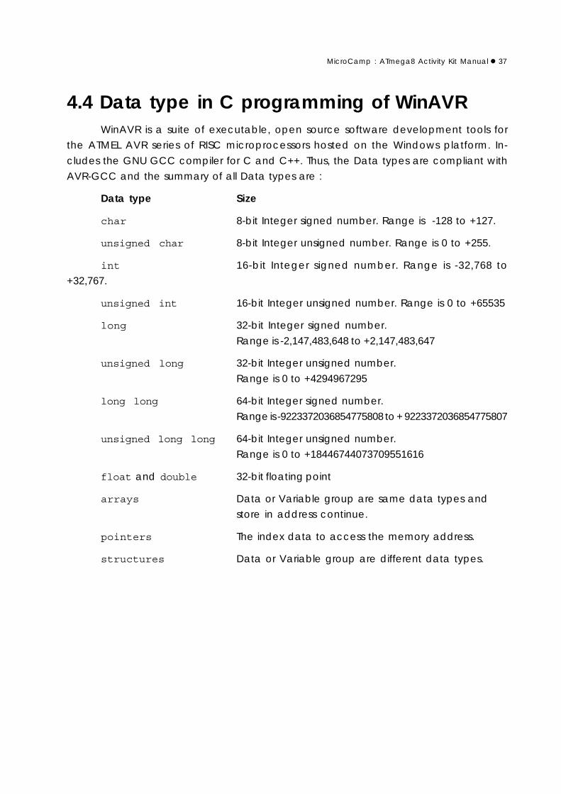
4.4 Data type in C programming of WinAVRWinAVR is a suite of executable, open source software development tools for
the ATMEL AVR series of RISC microprocessors hosted on the Windows platform. In-
cludes the GNU GCC compiler for C and C++. Thus, the Data types are compliant with
AVR-GCC and the summary of all Data types are :
Data type Size
char 8-bit Integer signed number. Range is -128 to +127.
unsigned char 8-bit Integer unsigned number. Range is 0 to +255.
int 16-bit Integer signed number. Range is -32,768 to
+32,767.
unsigned int 16-bit Integer unsigned number. Range is 0 to +65535
long 32-bit Integer signed number.
Range is -2,147,483,648 to +2,147,483,647
unsigned long 32-bit Integer unsigned number.
Range is 0 to +4294967295
long long 64-bit Integer signed number.
Range is -9223372036854775808 to + 9223372036854775807
unsigned long long 64-bit Integer unsigned number.
Range is 0 to +18446744073709551616
float and double 32-bit floating point
arrays Data or Variable group are same data types and
store in address continue.
pointers The index data to access the memory address.
structures Data or Variable group are different data types.

38MicroCamp : ATmega8 Activity Kit Manual
4.5 Numerical system in C program of WinAVRWinAVR compiler has 3 types of numerical system in C program.
1. Decimal number
2. Binary number The format is 0bBBBBBBBB. Thus, B is 0 or 1
3. Hexadecimal number The format is 0xHHHHHHHH. Thus, H is 0 to 9, A to F
Example 4-7
12$34)-
&!56'7&!5-'7&!5,'7&!5)'7&!5'7&!55'7&!5'7&!5'
8)-
Example 4-8
-2$34-56
&!5,'7&!5)'7&!5'7&!55'7&!5'7&!5'7&!59'
7&!51'7&!56'7&!5-'7&!5,'7&!5)'7&!5'7&!55'
7&!5'7&!5'8-56
Example 4-9
!3!::45,,
&,!-'7&,;-'85,,!::$
Example 4-10
!3!4)9
&!-'7&!-'8)9!$
4.6 Variable declarationVariable declaration in C program of WinaVR is similar to ANSI-C programming.
The General form is
type variable_name;
Thus;
type is The result data type
variable_name is variable declared
such as :

MicroCamp : ATmega8 Activity Kit Manual 39
int a; // Declare a variable as int data type
long result; // Declare result variable as long data type
float start; // Declare start vairable as float data type
int x,y; // Declare 2 variables; x and y. Data types are int
float p,q,r; // Declare 3 variables; p, q and r. Data types are float.
In addition, programmers can declare the variables and set the initial value such as
int =100; // Declare x variable.
// Data type is an integer and the initial value is 100.
int x=15,y=78; // Declare x and y variable.
// Data type is an integer and the initial value are
// x=15 and y=78.
long p=47L,q=31L; // Declare p and q variable. Data type is long
// and initial value are p=47 and q=31.
4.7 Data type conversionThe general form of the conversion is
(type)variable
Thus; type is The result data type that is required
variable is the variable that is required to convert the data type
Example 4-11
int x=100; // ( x% % *,,
float y=43.67,z; //( yz% y./012
z = y+(float)x ; // 3 % z yx
// x
// " % !4
// 5.*/012
Example 4-12
int a=50; //( a% %
//$,
long b=23L,c; //( bc% b0
c = b*(long)a; // 3 % ba
// a"6 b c
// " %
// (long)a
// c.**$,

40MicroCamp : ATmega8 Activity Kit Manual
4.8 Type of variable in WinAVR compiler4.8.1 Array
4.8.1.1 One dimension Array
The declaration form of this one dimension array is :
type name[size];
Thus ;
type is Data type of an Array variable
name is the Array variable name
size is the Numberof size of Array (optional)
Accessing the member of each array has the general form as follows :
name[index]
Thus ; index is the Index value for pointing to any member in array. This param-
eter can be a number or a variable, but these must be integer format.
Example 4-13
:
char arr[4];
<$ <)2
arr[0] <! =>
arr[1] <! =>
arr[2] <! =5>
arr[3] <! =>
arr[0]arr[1]arr[2]arr[3] $(
$arr 4)$

MicroCamp : ATmega8 Activity Kit Manual 41
Example 4-14
char dat[8] = 1,3,5,7,9,11,13,15 ;
$3dat<1
dat[0] = 1;
dat[1] = 3;
dat[2] = 5;
dat[3] = 7;
dat[4] = 9;
dat[5] = 11;
dat[6] = 13;
dat[7] = 15;
:
char i , j ;
i = 3;
j = dat[i]; // j = dat[i] ==> j = dat[3] ==> j = 7
/*+86*/
Example 4-15char dat[4] = “ abcd” ;
$3dat<)
dat[0] = ‘a’;
dat[1] = ‘b’;
dat[2] = ‘c’;
dat[3] = ‘d’;
:
char i , j ;
i = 3;
j = dat[i]; // j = dat[i] ==> j = dat[3] ==> j = ‘d’
/*The result isj = ‘d’ */
$ <

42MicroCamp : ATmega8 Activity Kit Manual
4.8.1.2 The 2-Dimension Array
The declaration form of this two dimension array is :
type name[x][y];
This command shows a 2 dimensional array type variable.
type is the Data type of Array variable
name is the Array variable name
x is the Number of row in the array
y is the Number of column in the array
For example :
int a[2][5];
It is declaring that “a” is a 2 dimensional array. It has integer types values
in 10 cells.
a[0][0], a[0][1], a[0][2], a[0][3], a[0][4] ,
a[1][0], a[1][1], a[1][2], a[1][3], a[1][4]
For the setting of the cell values, this can be done as such:
int menu[3][4] =1,3,4,9 , 2,8,0,5;
This would mean that :
menu[0][0] = 1 menu[0][1] = 3 menu[0][2] = 4 menu[0][3] = 9
menu[1][0] = 2 menu[1][1] = 8 menu[1][2] = 0 menu[1][3] = 5
menu[2][0] = 0 menu[2][1] = 0 menu[2][2] = 0 menu[2][3] = 0

MicroCamp : ATmega8 Activity Kit Manual 43
The Operation in C program of Win AVR compiler can be divided into 3 groups,
which are the Arithmetic operator, Relation & logic operator and Bitwise operator.
5.1 Arithmetic operatorThis group can be summarized into the following:
Operator Meaning
+ Addition
- Subtraction
* Multiplication
/ Division
% Modulo
++ Increment
- - Decrement
+= Add with the Right-hand value
- = Subtract with the Right-hand value
*= Multiply by the Right-hand value
/= Divide by the Right-hand value
%= Modulo by the Right-hand value
5.1.1 Addition (+) and Subtraction (-)Example 5-1
int a = 12;
a = a + 3;
Chapter 5Operators of WinAVR compiler

44MicroCamp : ATmega8 Activity Kit Manual
Example 5-2
int a = 12;
a = a - 3;
!
"
5.1.2 / and % divisionThe different of both division is :
1. / is the division of numbers which will return an integer.
2. % is the division of numbers which will return with the remainder. Called
as Modulo.
Example 5-3
int x , y , z;
x = 10;
y = x/3;
z = x%3;
y = x/3;y = 10/3#$%&
z = x%3;z = 10%3' $%#&
5.1.3 ++ and - - operationExample 5-4
int y = 5;
y++;
#()# *#y++;!
+y = y + 1;!
Example 5-5
int y = 5;
y - -;
#()#" ,# y - -;!
+y = y - 1;!

MicroCamp : ATmega8 Activity Kit Manual 45
5.1.4 += and - = operationThe operation of both operations can be summarized as follows:
y +=a; gives the result similar to y = y + a;
y -=a; gives the result similar to y = y - a;
Example 5-6
int x = 100;
x += 10;
5.1.5 *= , /= and %= operationThe operation of all operators can be summarized as follows:
y *=a; gives the result similar to y = y * a;
y /=a; gives the result similar to y = y/a;
y %=a; gives the result similar to y = y%a;
Example 5-7
int x, y, z;
x = y = z = 120;
x *= 4;
y /= 4;
z %= 4;
46MicroCamp : ATmega8 Activity Kit Manual
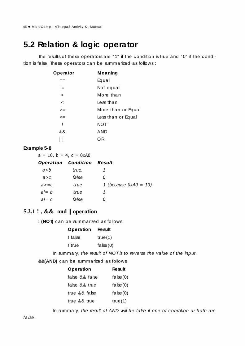
5.2 Relation & logic operatorThe results of these operators are “1” if the condition is true and “0” if the condi-
tion is false. These operators can be summarized as follows :
Operator Meaning
== Equal
!= Not equal
> More than
< Less than
>= More than or Equal
<= Less than or Equal
! NOT
&& AND
|| OR
Example 5-8 - ,!-)-
!
"
"
! (NOT) can be summarized as follows
Operation Result
! false true(1)
! true false(0)
In summary, the result of NOT is to reverse the value of the input.
&&(AND) can be summarized as follows
Operation Result
false && false false(0)
false && true false(0)
true && false false(0)
true && true true(1)
In summary, the result of AND will be false if one of condition or both are
false.

MicroCamp : ATmega8 Activity Kit Manual 47
||(OR) can be summarized as follows
Operation Result
false || false false(0)
false || true true(1)
true || false true(1)
true || true true(1)
In Summary, the result of OR will be true if one of the condition or both
are true.
Example 5-9
. - ,!-)-
!
"
"
#
"!
"!
"!
""!
""!
#
"!$$! !
"!$$! !
"!$$""! !
"! %% ! !
"!%%! !
"!%%""! !
"!%%""! !

48MicroCamp : ATmega8 Activity Kit Manual
5.3 Bitwise OperatorThe operators can be summarized as follows
Operator Meaning
~ Invert bit
& Bit AND
| Bit OR
^ Bit XOR
<< Shift Left
>> Shift Right
<<= Shift left and Store the result to variable
>>= Shift right and Store the result to variable
&= AND operation with Store the result to variable
|= OR operation with Store the result to variable
^ = XOR operation with Store the result to variable
5.3.1 Bit logic Operation~ operation can summary as follows
Operation Result~ 0 1
~ 1 0
& operation can summary as follows
Operation Result0 & 0 0
0 &1 0
1 & 0 0
1 & 1 1
| operation can summary as follows
Operation Result0 | 0 0
0 | 1 1
1 | 0 1
1 | 1 1
^ operation can summary as follows
Operation Result0 ^ 0 0
0 ^1 1
1 ^ 0 1
1 ^ 1 0

MicroCamp : ATmega8 Activity Kit Manual 49
Example 5-10
.
int x,y,result1,result2,result3,result4;
x = 0x9C;
y = 0x46;
/0
result1 = x&y;
result2 = x|y;
result3 = x^y;
result4 = ~x;
/#!++ #
)-)1-------- -- --$ !#2 *" &
#-),*--------- --- -
$ & $-------- -- --&3$--------- --- -&
-------- -- --(.
--------- --- -
$& $-------- -- --& 4 $--------- --- -&
-------- -- --5%
--------- --- -
$& $-------- -- --& 6 $--------- --- -&
-------- -- --75%
--------- --- -
$,& , 8$-------- -- --& &'

50MicroCamp : ATmega8 Activity Kit Manual
5.3.2 Shift bit operationIn the shifting bit operation, you must determine the number of shifting such as :
dat = dat<<4;
It means shifting to the left of the dat variable 4 times and storing the
result into the dat again.
Another example is
dat = dat>>1;
It means shifting to the right of the dat variable 1 bit and storing the result
into the dat again.
Example 5-11
int dat, x1, x2;
dat = 0x93;
/0
x1 = dat<<1;
x2 = dat<<2;
-)-------- -- --
dat 0000000010010011
X1 0000000100100110
X2 0000001001001100
$ &) 00 +
( #( ))
$&)00 +
((* #+ ))
Example 5-12int a , b , c;
a = 0x7A;
b = 0x16;
c = 0xFD;
/0
a &= 0x3C;
b |= 0x51;
c ^= 0xD0;

MicroCamp : ATmega8 Activity Kit Manual 51
$ &/a &= 0x3C;, 9a = a & 0x3C;+0
$-):&(.-)1 !;
9+ $--------- - -&3$---------- --&
--------- - -
(.
---------- --
$&/b |= 0x51;9b = b |= 0x51;+0
$-) *&5% -) !;
9+ $----------- - -&4$--------- - --- &
----------- - -
5%
--------- - ---
$&/c ^= 0xD0; 9c = c ^= 0xD0;+0!
$-)/.&75% -).- !; !
9+ !$-------- - &6$-------- - ----&
-------- -
75%
-------- - ----

52MicroCamp : ATmega8 Activity Kit Manual

MicroCamp : ATmega8 Activity Kit Manual 53
The MicroCamp Activity kit comes with a lot of libraries to support developers
and learners. It includes Input/Output port control library, Analog input reading library,
Delay time library, Sound library and Motor control library.
The summary of all libraries are as follows :
in_out.h Library for Sending digital data to the output port and
Reading the Digital input port.
sleep.h Delay function library
analog.h Analog input reading library. Assist in reading of analog data
from P0 to P4 port
led.h LED control library
motor.h DC motor control library
sound.h Sound generator library
timer.h Timer function library
All libraries must be stored in the same folder for proper linking of paths and to
avoid any errors. Learners can see details of all libraries from the MicroCamp_includefolder in CD-ROM which is bundled with the MicroCamp Activity kit.
Chapter 6Library and Specific command
in MicroCamp kit

54MicroCamp : ATmega8 Activity Kit Manual
6.1 Command in in_out.h library6.1.1 Digital input port reading function
in_b : Port B input reading function
in_c : Port C input reading function
in_d : Port D input reading function
Function format :
char in_a(x)
char in_b(x)
char in_c(x)
char in_d(x)
Parameter :
x - determines the number of the input port that will be used. The value is 0 to 7.
Return value :
“0” or “1”
Example 6-1
char x=0; // x
x = in_b(2); // x
Example 6-2
char x=0; // x
x = in_d(4); // x
Example 6-3
#include <avr/io.h> //
#include <in_out.h> //
#include <sound.h> //
void main()
while(1)
if (in_d(2)==0) // ! "
sound(3000,100); // # !

MicroCamp : ATmega8 Activity Kit Manual 55
6.1.2 Sending data to output port functionThis function determines the port pin, configures it to output and sends the value
to that port. These function does not return any values.
out_b : Port B output sending function
out_c : Port C output sending function
out_d : Port D output sending function
Function format :
out_b(char _bit,char _dat)
out_c(char _bit,char _dat)
out_d(char _bit,char _dat)
Parameter :
_bit - select port’s pin. Range is 0 to 7.
_dat determine the output value “0” or “1” to output pin
Example 6-4
out_c(5,0); // $%& '
out_d(1,1); // $!& !
Example 6-5
#include <avr/io.h> //
#include <in_out.h> //
#include <sound.h> //
void main()
while(1) // (
out_d(1,1); // ) $!& ! * (+
sleep(300); // % ,
out_d(1,0); // )$%&! *(+##
sleep(300); // % ,

56MicroCamp : ATmega8 Activity Kit Manual
6.1.4 Invert logic output port function
toggle_b : Port B output invert logic function
toggle_c : Port C output invert logic function
toggle_d : Port D output invert logic function
Function format :
toggle_b(x)
toggle_c(x)
toggle_d(x)
Parameter :
x Determines the port number. The value is 0 to 7.
Example 6-6
toggle_c(5); // '
toggle_d(1); // !
6.2 Delay function in sleep.h libraryThis library only has one function. It is the sleep function. Developers can use this
function to pause or delay the operation in millisecond unit.
Function format :
void sleep(unsigned int ms)
Parameter :
mstime value in millisecond unit. Range is 0 to 65,535.
Example 6-7
sleep(20); // %-.-
sleep(1000); // !-.-
MicroCamp : ATmega8 Activity Kit Manual 57
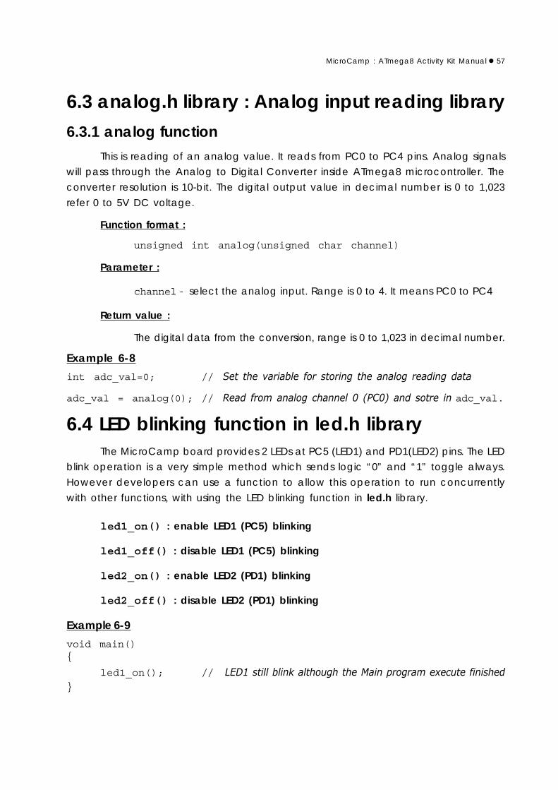
6.3 analog.h library : Analog input reading library6.3.1 analog function
This is reading of an analog value. It reads from PC0 to PC4 pins. Analog signals
will pass through the Analog to Digital Converter inside ATmega8 microcontroller. The
converter resolution is 10-bit. The digital output value in decimal number is 0 to 1,023
refer 0 to 5V DC voltage.
Function format :
unsigned int analog(unsigned char channel)
Parameter :
channelselect the analog input. Range is 0 to 4. It means PC0 to PC4
Return value :
The digital data from the conversion, range is 0 to 1,023 in decimal number.
Example 6-8
int adc_val=0; // #
adc_val = analog(0); // / #- % 0%1 adc_val.
6.4 LED blinking function in led.h libraryThe MicroCamp board provides 2 LEDs at PC5 (LED1) and PD1(LED2) pins. The LED
blink operation is a very simple method which sends logic “0” and “1” toggle always.
However developers can use a function to allow this operation to run concurrently
with other functions, with using the LED blinking function in led.h library.
led1_on() : enable LED1 (PC5) blinking
led1_off() : disable LED1 (PC5) blinking
led2_on() : enable LED2 (PD1) blinking
led2_off() : disable LED2 (PD1) blinking
Example 6-9
void main()
led1_on(); // (+!2-.#

58MicroCamp : ATmega8 Activity Kit Manual
6.5 motor.h : Motor control library6.5.1 motor function
This function is used for controlling the DC motor driver circuit on the MicroCamp
controller board.
Function format :
void motor(char _channel,int _power)
Parameter :
_channel select motor output channel. On MicroCamp control board
has 2 channels; 1 and 2.
_power - determine the power apply for motor output.Range is -100 to 100.If value is positive (1 to 100), the motor will spin in a direction.
If value is negative (-1 to -100), the motor spin the other direction.
If the value is 0, motor will stop but this do not lock the motor’s
shaft.Example 6-10
motor(1,60); // - !34%5# 3 ................motor(1,-60); // -!34%5#3
Example 6-11
motor(2,100); // -3#30!%%51
6.5.2 motor_stop functionIt is the brake motor function. The motor’s shaft will lock after active this function.
Function format :
void motor_stop(char _channel)
Parameter :
_channel - select motor output channel. This parameter has 3 values.
1 for braking motor at OUT1 channel
2 for braking motor at OUT2 channel
ALL for braking all motor channel
Example 6-12
motor_stop(1); //- !
motor_stop(2); //-
motor_stop(ALL); //- 0! 1

MicroCamp : ATmega8 Activity Kit Manual 59
6.5.3 motor_off functionThis function is used for stopping the motor operation and to turn-off the voltage
of all motor outputs. This function is similar to the motor function which sets the power
value to 0.
Function format :
void motor_off()
6.5.4 forward functionThis function is used for driving DC motor to move the robot in forward direction.
Function format :
void forward(int speed)
Parameter :
speed - determine the power applied to motor output. Range is 0 to 100.
6.5.5 backward functionThis function is used for driving DC motor to move the robot in a backward direction.
Function format :
void backward(int speed)
Parameter :
speed - determine the power applied to motor output. Range is 0 to 100.
6.5.6 s_left functionThis function is used for driving the DC motor to spin the robot in a left direction.
Function format :void s_left(int speed)
Parameter :
speed - determine the power applied to motor output. Range is 0 to 100.
6.5.7 s_right functionThis function is used for driving the DC motor to spin the robot in a right direction.
Function format :void s_right(int speed)
Parameter :
speed - determine the power applied to motor output. Range is 0 to 100.

60MicroCamp : ATmega8 Activity Kit Manual
6.6 sound.h : Sound generator libraryThis function is used for setting the sound frequency which drives the piezo speaker
on the MicroCamp controller board to produce sounds.
Function format :void sound(int freq,int time)
Parameter :
freq - determine the frequency output in Hertz (Hz) unit.
time - determine the time value of sound output signal in millisecond unit.
Example 6-13
sound(2000,500); //67#'%%-
6.7 Counting time function in timer.h library6.7.1 timer_start function
Determine the start point of the timer. After this function, the timer value will be
cleared.
Function format :void timer_start(void)
6.7.2 timer_stop functionThis stops the timer and clears the counting value.
Function format :void timer_stop(void)
6.7.3 timer_pause functionPause timer counting. The value still remains.
Function format :void timer_pause(void)
6.7.4 timer_resume functionResume the counting after a pause from timer_pause function.
Function format :void timer_resume(void)

MicroCamp : ATmega8 Activity Kit Manual 61
6.7.5 msec functionRead the timer value in milliseconds.
Function format :unsigned long msec()
Return value :
Time value is in millisecond. The data type is a “long” variable.
6.7.6 sec functionRead the timer value in seconds.
Function format :unsigned long sec()
Return value :
Time value is in second. The data type is a “long” variable.
Example 6-14
#include <in_out.h>
#include <sleep.h>
#include <timer.h>
void main() // 2 -
timer_start(); // #-
while(1) // +
if(msec()>500) // - -'%%"
timer_stop(); // -
toggle_c(5); // * (+ % '
timer_start(); // -

62MicroCamp : ATmega8 Activity Kit Manual

MicroCamp : ATmega8 Activity Kit Manual 63
This chapter focus learning the applications of the MICROCAMP microcontroller.
The building of a robot integrates knowledge and technology which includes electronics,
programming, mechanical movements, and thinking process. The Microcamp Activity kit
supports this concept. This kit includes all parts for building a simple mobile robot. Users
can learn about programming and how to apply the microcontroller aspects via robotic
activities.
The Mobile robot in MICROCAMP has 2 DC Motor gearboxes for moving and 4
sensors for detecting external values. These are 2 touch sensors and 2 Infrared Reflector
Line tracking sensors for use in black and white line following.
48:1 DC motorgearbox x 2
Circle base plateBox holder x 1
Wheel andTire set x 2
Plastic spacer set x 1 Nut and Screw set x 1
Infrared reflector x 22mm. Self-tappingscrew x2
25mm. metalspacer x 2
Ploastic joiners (Straight, Right angleand Obtuse)
Swithc module x 2
MicroCamp board
Part list
Chapter 7Building robot with
MicroCamp kit

64MicroCamp : ATmega8 Activity Kit Manual
Construction1. Fix on the 2 wheels with the rubber tires and attach them to the DC Gearbox with the 2
of the 2mm. self-tapping screws provided in the kit.
2. Install both the DC Gearboxes on the circular base plate at the specific positions shown
in the picture with 4 of 3 x 6mm. machine screws.
3. Insert the 3 x 10mm. machine screws through the hole at the corner of the Box holder
with 25mm. and 2 of 3 mm. spacers.
4. Place the Box holder from step 3 on the top of the Circle base plate and attach them
with 3 x 10mm. screws at the specific positions.

MicroCamp : ATmega8 Activity Kit Manual 65
5. Insert a 3x15mm. machine screw through the Infrared Reflector sensor, followed by 2 of
the 3mm. spacer. Do on both sides for this.
6. Attach both the Infrared Reflector structures from step 5 at the suitable holes at the
bottom and front of the robot base. Tighten with a 3mm. nut.
7. Observe the distance from the floor to the sensors. The suitable distance is 3 to 5 mm.
8. Place MicroCamp board on the box holder. Connect sensor cables and motor cables
following the diagrams shown. (P0 for Right sensor and P1 for Left sensor).
!

66MicroCamp : ATmega8 Activity Kit Manual
9. Attach the Straight joiner with robot base at front-right side by 3 x 10mm. machine screw
and 3mm. nut. Attach 2 pieces.
10. Connect the Obtuse joiner at the end of Straight joiner. Attach the right angle joiner
with Switch module by 3 x 10mm. machine screw and 3mm. nut. Make 2 sets. Bring these
structures to connect at the end of the Obtuse joiner. Connect 2 sides.
11. Connect the Left Switch module cable to the P2 (PC2) connector and the Right Switch
module cable to the P3 (PC3) connector. Put 4 AA batteries into battery holder at the
back of MicroCamp board. The MicroCamp robot is ready for programming now.

MicroCamp : ATmega8 Activity Kit Manual 67
Learning about the Switch circuit
"# $
%
&
&
More information of Infrared Reflector
&
" #
!' # ()
* *+,-"
** # * +
# # ) .
*# * /& "$"000
#01 2
" +013# ,-" +
( ##
!"#
& * #+ #

68MicroCamp : ATmega8 Activity Kit Manual
#include <in_out.h>#include <sleep.h>#include <motor.h> // Motor driver libraryvoid main()
while(1) // Endless loop
forward(100); // Move the robot forward.sleep(1000); // Delays 1 second.backward(100); // Move the robot backward.sleep(1000); // Delays 1 second.
Activity 1Basic movement of MicroCamp robot
Activity 1-1 Forward and Backward movementA1.1 Open the AVR Studio to create the new project and write the C program following
the Listing A1-1. Build this project.
A1.2 Connect the PX-400 programmer to the MicroCamp board on The MicroCamp robot
at the In-System Prog. connector. Turn-on the Robot. Downlaod the HEX code to the robot.
A1.3 Turn-off power and Remove the ISP cable.
A1.4 Make sure the robot is on a flat surface. Turn-on the power and observe the operation.
The MicroCamp robot moves forward. See both LED motor indicators light in green
color. After 1 second, both indicators change color to red and the robot moves backward.
If this is incorrect you will need to re-connect the motor cable to its opposite port /
polarity. Do this until your robot moves correctly. Once its done, Use this motor port
configuration for all your programming activities from now on. The robot will move forward
and backward continually until you turn off its power.

MicroCamp : ATmega8 Activity Kit Manual 69
#include <in_out.h>#include <sleep.h>#include <motor.h>void main()
while(1)
while((in_d(2)==1)); // Loop for checking SW1 pressedmotor(1,100); // Apply full power for Motor 1motor(2,30); // Apply 30% power for Motor 2while((in_d(3)==1)); // Loop for checking if SW2 pressedmotor_off(); // Stop all motors.
Program description
In Listing A1-2, the forward and backward com--mands are not used for driving the robot. The MOTORfunction is used instead. This function can control bothmotor outputs separately. This means that you can controlboth the motor’s speed differently.
When both speeds are not equal, the robot willmove towards the direction where the motor is of a lowerspeed. If the speed difference is great, the MicroCamprobot will move in circles.
The While command is used in this program. If SW1at PD2 port is being pressed, the LOGIC value of “O” isreturned. The first conditional loop is false. It thencontinues with the second conditional loop. If SW2 at PD3port is press, the Program will stop both motors. The Robotwill stop its movement.
Activity 1-2 Circle-shape movement controlA1.5 Create a new project file and write the following C Codes shown in A1-2.
A1.6 Connect the PX-400 programmer to the MicroCamp board on The MicroCamp robot
at the In-System Prog. connector. Turn-on the Robot. Downlaod the HEX code to the robot.
A1.7 Turn-off power and Remove the ISP cable.
A1.8 Make sure the robot is on a flat surface. Turn-on the power and observe the robot.
The robot will be activated when you press SW1 and move in circles continually
until you press the SW2 to stop the robot movement.

70MicroCamp : ATmega8 Activity Kit Manual
#include <in_out.h>#include <sleep.h>#include <motor.h>void main()
while(1) // Looping
if (in_d(2)==0) // Check SW1 pressing
while(1)
forward(100); // Move forward with full speed 0.9 secondsleep(900);s_right(50); // Turn right with 50% speed 0.3 secondsleep(300);
if (in_d(3)==0) // Check SW2 pressing
while(1)
forward(100); // Move forward with full speed 0.9 secondsleep(900);s_left(50); // Turn left with 50% speed 0.3 secondsleep(300);
Activity 1-3 Square-shape movement controlA1.9 Create a new project file and write the following C Codes shown in A1-3. Connect
the PX-400 programmer box to the MicroCamp board on The MicroCamp robot at the In-
System Prog. connector. Turn-on the Robot. Downlaod the HEX code to the robot.
A1.10 Turn-off power and Remove the ISP cable. Make sure the robot is on a flat surface.
Turn-on the power and observe the robot.
The robot will be activated if SW1 or SW2 is being pressed. If you Press SW1, the
robot will move forward and turn left continually, making a square. If you press SW2, the
operation is vice versa.

MicroCamp : ATmega8 Activity Kit Manual 71
Activity 2Object detection with Collision
Activity 2-1 Simple collision detectionThis activity is program the robot to detect the collision of both switches at the front
of the MicroCamp robot. After a collision is encountered, the robot will move backward
and change the its direction of movement.
A2.1 Create a new project file and write the following C Codes shown in A1-4. Build this
project.
A2.2 Connect the PX-400 programmer box to the MicroCamp board on The MicroCamp
robot at the In-System Prog. connector. Turn-on the Robot.
A2.3 Download the HEX code to the robot.
A2.4 Turn-off power and Remove the ISP cable.
A2.6 Prepare the demonstration area by placing and securing boxes or objects on the
surface.
A2.7 Bring the robot into the demonstration area .Turn-on the power and observe the
robot. The MicroCamp robot will read both switch status from PD2 and PC3 port. If any
switch is pressed or touches some object, the result is logic “0”.
In a normal operation, the robot will move forward continually.
If the Left Switch module touches any object, the robot will move backward and
change its moving direction to its right to avoid the object.
If the Right Switch module touches any object, the robot will move backward and
change its moving direction to its left to avoid the object.

72MicroCamp : ATmega8 Activity Kit Manual
!" #
#include <in_out.h>#include <sleep.h>#include <motor.h>void main()
while((in_d(2)==1)); // Loop until SW1 is pressed to start the program.while(1) // Repeat loop
if (in_c(2)==0) // Check status of the right switch.
backward(100); // If ther is a collision, the robot moves backward// for 0.4 second
sleep(400);s_left(50); // and turns left for 0.3 second.sleep(300);
else if (in_c(3)==0) // Check status of the left switch.
backward(100); // If ther is a collision, the robot moves backward// for 0.4 second
sleep(400);s_right(50); // and turns right 0.3 second.sleep(300);
else
forward(100); // No collision is deteced,// the robot moves forward continually.

MicroCamp : ATmega8 Activity Kit Manual 73
#include <in_out.h>#include <sleep.h>#include <motor.h>#include <sound.h> // Sound libraryvoid main()
unsigned char cnt_=0; // Declare variable for counting the number of// collision both left and right.
while((in_d(2)==1)); // Wait for SW1 is pressed to start operationsound(3000,100); // Beep at once
while(1) // Looping
if (in_c(2)==0) // Check the right-side collision
if ((cnt_%2)==0) // Check the counter as even number or not.// If yes, means the previous collision is left-// side collision.
cnt_++; // Increment the counterelse // If not left-side collision,cnt_=0; // clear the counterbackward(100); // Move backward 0.4 secondsleep(400); //s_left(50); // Turn leftif (cnt_>5) // Check the counter over 5 or not.
sleep(700); // If over, turn left more 0.7 second.sound(3000,100); // Drive sound to piezo speaker
cnt_=0; // Clear counter
$
%$ &
Activity 2-2 Trapped in a corner situationWhen the Robot is in a corner, it is caught in between whereby to the left or right is
a wall. This causes continous hitting of the walls and thus trapping the robot in this corner.
The solution is to modify your exiting C Code from A2-1 to that which is shown in A2-2.
A2.8 Create a new project file for making the C program according to Listing A2-2.
A2.9 Connect the PX-400 programmer box to the MicroCamp board on The MicroCamp
robot at the In-System Prog. connector. Turn-on the Robot.
A2.10 Prepare the demonstration area by placing and securing boxes or objects on the
surface.
A2.11 Bring the robot into the demonstration area .Turn-on the power and observe the
robot.
The robot will move forward and check for collision. If this happens over 5 times
consecutively, the robot will spin 180 degrees to change its direction.

74MicroCamp : ATmega8 Activity Kit Manual
else // If counter is less than 5, sleep(300); // Set time value for turning to 0.3 second.
else if (in_c(3)==0) // Check the leftt-side collision
if ((cnt_%2)==1) // Counter is odd number or not.// If yes, the previous collision is right-side.
cnt_++; // Increment counterelsecnt_=0; // If not, clear counterbackward(100); // Robot move backward for 0.4 secondsleep(400); //s_right(50); // Turn right for 0.3 secondsleep(300); //
else // If not collision, move forward.forward(100);
$
%&

MicroCamp : ATmega8 Activity Kit Manual 75
From the 2 first activities, these show how to read the digtal input signal and to get
the data to control robot movement. In this activity, there will be many activities about
reading analog inputs and processing the data to detect black and white areas. It also
detects Black and white line to control the robot to move along the line with conditions.
The MicroCamp robot has 5 analog inputs that directly connects to the PC0 to
PC4 of ATmega8 microcontroller. This microcontroller contains the 10-bit analog to digital
converter (ADC) module. The digital conversion data is 0 to 1023 in decimal number format.
C programming for this activity require a library file. It is the analog.h file. Functions
in this library will define relate the input port to the analog input and reads data from ADC
module to store in its memory. The resulting data range is 0 to 1023 in decimals or 0000H to
03FFH in hexadecimals.
The important devices in this activity is the 2 Infrared Reflector modules. They are
installed at the bottom of the robot base. They are used to detect the surface’s color
(black and white) including the white and black line. The Line tracking robot activity is the
classic activity. It shows the basic robot’s programming performance.
Activity 3-1 Testing black and white areaThe MicroCamp robot is attached with 2 of Infrared Reflector module at bottom of
the robot base ready. Thus, this activity will only dwell on programming.
Before develop the robot to track the line, developers must program the robot to
detect the difference between black and white color surface.
(A) White surface testingThis sub-activity presents how to detect the white surface. The Listing A3-1 is C program
for testing Infrared Reflector operation. After execution, the program will wait for SW1 or
SW2 pressing.
If press SW1 : select to read data from P0 or PC0 analog port
If press SW2 : select to read data from P1 or PC1 analog port
After pressing the switch, the program will read data at the port pin continuously
and will not switch to read another sensor unless the RESET button is pressed. Developers
must press both switches to get the sensor’s data.
Activity 3Line tracking robot
76MicroCamp : ATmega8 Activity Kit Manual
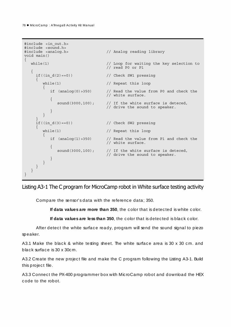
#include <in_out.h>#include <sound.h>#include <analog.h> // Analog reading libraryvoid main()
while(1) // Loop for waiting the key selection to// read P0 or P1
if((in_d(2)==0)) // Check SW1 pressing
while(1) // Repeat this loop
if (analog(0)>350) // Read the value from P0 and check the// white surface.
sound(3000,100); // If the white surface is deteced,
// drive the sound to speaker.
if((in_d(3)==0)) // Check SW2 pressing
while(1) // Repeat this loop
if (analog(1)>350) // Read the value from P1 and check the// white surface.
sound(3000,100); // If the white surface is deteced,
// drive the sound to speaker.
' $
Compare the sensor’s data with the reference data; 350.
If data values are more than 350, the color that is detected is white color.
If data values are less than 350, the color that is detected is black color.
After detect the white surface ready, program will send the sound signal to piezo
speaker.
A3.1 Make the black & white testing sheet. The white surface area is 30 x 30 cm. and
black surface is 30 x 30cm.
A3.2 Create the new project file and make the C program following the Listing A3-1. Build
this project file.
A3.3 Connect the PX-400 programmer box with MicroCamp robot and download the HEX
code to the robot.

MicroCamp : ATmega8 Activity Kit Manual 77
A3.4 Place the robot on the black surface first. Turn on the power and press SW1 switch.
The Robot does not move.
A3.5 Place the robot on the white surface and try to roll the robot.
The robot produces sounds when its on a white surface.
A3.6 Press the RESET switch. Place the robot on the black surface again. Press switch SW2
to test the operation of the Infrared Reflector at P1 port. Observe the robot’s operation.
After press SW2, robot will get data from sensors at P1 port and compare the
reference value ; 350. If the reading value more than 350, means the robot detects the
white area. It send sound signal to drive a piezo speaker. From step A3.6, robot detects
the black surface then do not work anything.
A3.7 Place the robot on the white surface and try to roll the robot.
Robot drives sound always above the white surface.
A3.8 If the robot cannot drive the signal when placed on the white surface in testing. The
solution is
(1) Decrease the reference value from 350 but not lower 100
(2) Adjust the sensor position to decrease the distance from the floor.
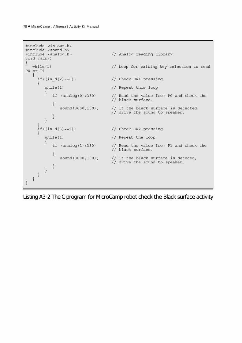
A3.9 The Listing A3-2 is C program for testing the black surface. Developers can test with
this program to check the black surface detection of robot to make sure the robot can
detect white and black surface well. The procedure is same in step A3.4 to A3.8. But the
decision criteria will change from higher 350 to lower 350 instead.
78MicroCamp : ATmega8 Activity Kit Manual
#include <in_out.h>#include <sound.h>#include <analog.h> // Analog reading libraryvoid main()
while(1) // Loop for waiting key selection to readP0 or P1
if((in_d(2)==0)) // Check SW1 pressing
while(1) // Repeat this loop
if (analog(0)<350) // Read the value from P0 and check the// black surface.
sound(3000,100); // If the black surface is detected,
// drive the sound to speaker.
if((in_d(3)==0)) // Check SW2 pressing
while(1) // Repeat the loop
if (analog(1)<350) // Read the value from P1 and check the// black surface.
sound(3000,100); // If the black surface is deteced,
// drive the sound to speaker.
( )($

MicroCamp : ATmega8 Activity Kit Manual 79
! "
#
Activity 3-2 Robot moves along the black line
(1) Both sensors read values that are white : The robot will move forward.
Thus, this program is written so that the robot moves forward normally.
(2) The left sensor reads black while the right sensor reads white : This occurs
when the robot is slightly turned to the right. Thus, the program is written for the robot to
move back left to resume its normal path.
(3) The left sensor read white while the right sensor reads black : This occurs
when the robot is slightly turned to the left. Thus, the program is written for the robot to
move back to the right to resume its normal path.
From all scenarioes, can make the C program in the Listing A3-3.
A3.10 Make the simple black line sheet. It has not the cross line. Most area is white color.
Size of sheet can determine suitable for your robot.
A3.11 Create the new project file and make the C program following the Listing A3-3. Build
this project file.
A3.12 Connect the PX-400 programmer box with MicroCamp robot and download the
HEX code to the robot. Turn off power and unplug ISP cable from the robot.
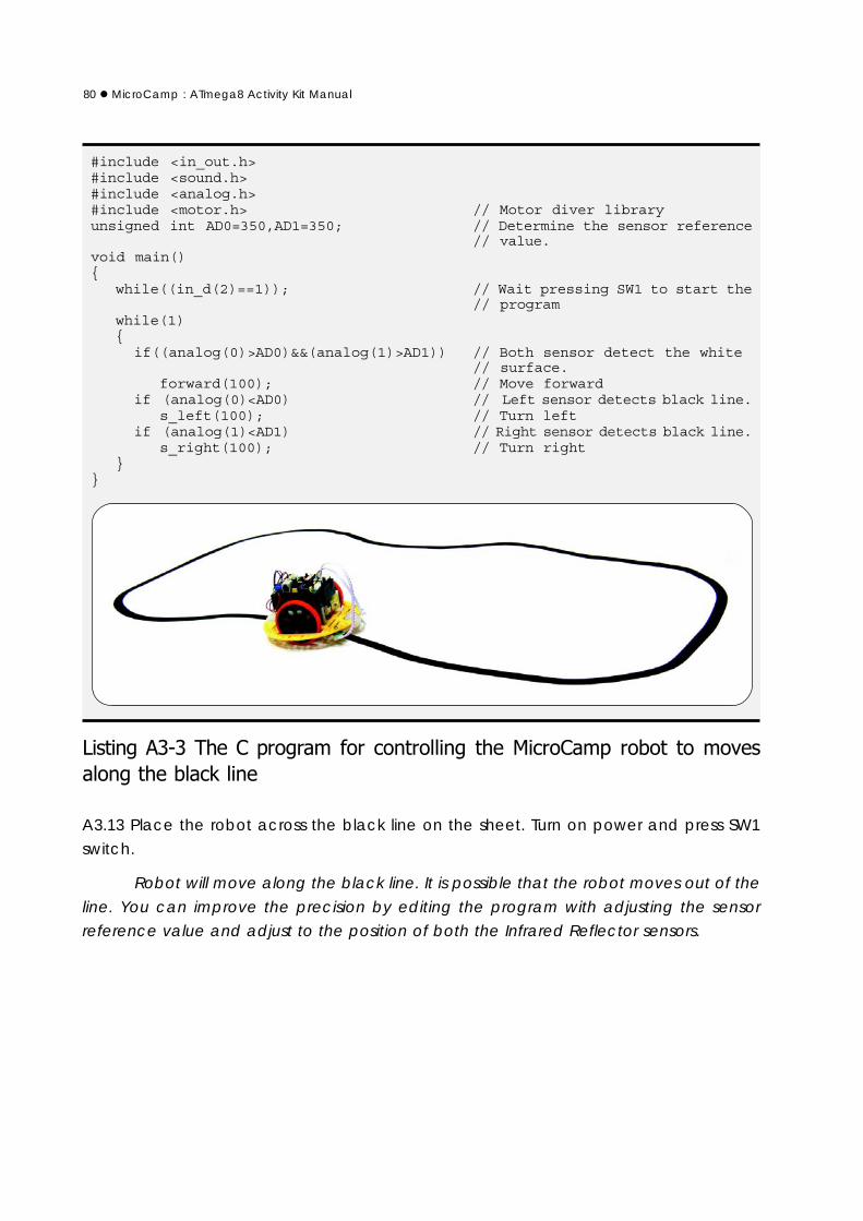
80MicroCamp : ATmega8 Activity Kit Manual
#include <in_out.h>#include <sound.h>#include <analog.h>#include <motor.h> // Motor diver libraryunsigned int AD0=350,AD1=350; // Determine the sensor reference
// value.void main()
while((in_d(2)==1)); // Wait pressing SW1 to start the// program
while(1)
if((analog(0)>AD0)&&(analog(1)>AD1)) // Both sensor detect the white// surface.
forward(100); // Move forwardif (analog(0)<AD0) // Left sensor detects black line.
s_left(100); // Turn leftif (analog(1)<AD1) // Right sensor detects black line.
s_right(100); // Turn right
(
A3.13 Place the robot across the black line on the sheet. Turn on power and press SW1
switch.
Robot will move along the black line. It is possible that the robot moves out of the
line. You can improve the precision by editing the program with adjusting the sensor
reference value and adjust to the position of both the Infrared Reflector sensors.

MicroCamp : ATmega8 Activity Kit Manual 81
Activity 3-3 Line crossing detectionFrom the activity 3-2, you can improve the MicroCamp robot so that it moves along
the black line and detect the junction or line with same 2 sensors. One thing to do is edit
the program.
When the robot moves to line crossing, both sensors will detect black line. You must
add the program for support this scenario. The improved C program is shown in the Listing
A3-4
A3.14 Improve the simple black line sheet from Activity 3-2. Add some cross lines. The number
will depend on your inquiry.
A3.15 Create the new project file and make the C program following the Listing A3-4. Build
this project file.
A3.16 Connect the PX-400 programmer box with MicroCamp robot and download the
HEX code to the robot. Turn off power and unplug ISP cable from the robot.
A3.17 Place the robot across the black line on the sheet. Turn on power and press SW1
switch.
Robot will move along the black line. When the robot detects the crossing, it will
brake and drive sound once. When it finds the second crossing, the robot will drive sound
twice and this will increase for the subsequent crossings.
Note : In the motor brake operation, robot will stop and lock the motor’s shaft immediately.
But sometimes, this is not enough. You must program the robot to move backwards for a
short time. This will cause the robot to stop at its position.

82MicroCamp : ATmega8 Activity Kit Manual
#include <in_out.h>#include <sound.h>#include <analog.h>#include <motor.h> // Motor control libraryunsigned int AD0=350,AD1=350; // Sensor reference valueunsigned char i=0,j=0; // Crossing counter variablevoid main()
while((in_d(2)==1)); // Wait for SW1 to be pressed to// start
while(1)
if((analog(0)<AD0)&&(analog(1)<AD1)) // Detect line-crossing.
j++;backward(30); // Move backward for a short time
to // to brake.sleep(10);motor_stop(ALL); // Motor brake functionfor (i=0;i<j;i++) // Repeat the loop
// line-crossing detection
sound(2500,100);sleep(50);
// Drive soundforward(100); // Move forward to closs oversleep(300); // the line.
if((analog(0)>AD0)&&(analog(1)>AD1)) // Both sensor detect white surface.
forward(100); // Move forwardif (analog(0)<AD0) // Left sensor detects black line.
s_left(100); // Turn leftif (analog(1)<AD1) // Right sensor detects black line.
s_right(100); // Turn right
*
( ##

MicroCamp : ATmega8 Activity Kit Manual 83
in_out.hRead and Write the digital data with any port#ifndef _IN_OUT_
#define _IN_OUT_
#define toggle_b(x) DDRB |= _BV(x); PORTB ^= _BV(x);#define toggle_c(x) DDRC |= _BV(x); PORTC ^= _BV(x);#define toggle_d(x) DDRD |= _BV(x); PORTD ^= _BV(x);char in_b(char _bit)
DDRB &= ~(1<<_bit);return((PINB & _BV(_bit))>>_bit);
char in_c(char _bit)
DDRC &= ~(1<<_bit);return((PINC & _BV(_bit))>>_bit);
char in_d(char _bit)
DDRD &= ~(1<<_bit);return((PIND & _BV(_bit))>>_bit);
void out_b(char _bit,char _dat)
DDRB |= _BV(_bit);if(_dat)
PORTB |= _BV(_bit);else
PORTB &= ~_BV(_bit);void out_c(char _bit,char _dat)
DDRC |= _BV(_bit);if(_dat)
PORTC |= _BV(_bit);else
PORTC &= ~_BV(_bit);void out_d(char _bit,char _dat)
DDRD |= _BV(_bit);if(_dat)
PORTD |= _BV(_bit);else
PORTD &= ~_BV(_bit);
#endif
MicroCamp librariessource program

84MicroCamp : ATmega8 Activity Kit Manual
sleep.hDelay function library#ifndef _sleep_#define _sleep_void sleep(unsigned int ms)
unsigned int i,j;for(i=0;i<ms;i++)
for(j=0;j<795;j++);#endif
analog.hAnalog reading input library
unsigned int analog(unsigned char channel)
unsigned int adc_val;ADMUX = 0x40;ADMUX |= channel; // Sigle end modeADCSRA = 0xC6;while((ADCSRA & (1<<ADSC)));adc_val = ADCL;adc_val += (ADCH*256);return(adc_val);
sound.hSound generator library#include <in_out.h>#include <sleep.h>void delay_sound(unsigned int ms)
unsigned int i,j;for(i=0;i<ms;i++)
for(j=0;j<200;j++);void sound(int freq,int time)
int dt=0,m=0; // Keep value and dt = 5000/freq; // Keep active logic delay
time = (5*time)/dt; // Keep counter for generate soundfor(m=0;m<time;m++) // Loop for generate sound(Toggle logic P0.12)
out_d(4,1);delay_sound(dt); // Delay for sound
out_d(4,0);delay_sound(dt); // Delay for sound
void sound_cnt(unsigned char cnt,int freq,int time)
unsigned char i;for (i=0;i<cnt;i++)
sound(freq,time);sleep(300);

MicroCamp : ATmega8 Activity Kit Manual 85
led.hLED control library// Library for LED indicator by Timer 2 interrupt every 5 ms#include <avr/interrupt.h>#include <avr/signal.h>#include <in_out.h>unsigned char LED=0;unsigned char LED_cnt;
SIGNAL (SIG_OVERFLOW2) // Interval 10 ms
TCNT2 = 178; // Reload interval 10 ms(TCNT2 = 178)LED_cnt++; // Increment Counterif (LED_cnt>30) // Check Counter 10 ms X 30
LED_cnt=0; // Clear Counterif (LED==1) // Check LED1 Enable
toggle_c(5);else if (LED==2) // Check LED2 Enable
toggle_d(1);else if (LED==3) // Check LED1 and LED2 Enable
toggle_c(5);toggle_d(1);
void interval_init() // Config. and Start up timer 0 TCCR2 |= (1<<CS22)|(1<<CS21)|(1<<CS20);
// Prescaler 1024,16 MHz,// 1 MC = 1024/16M = 64us/count
TIFR |= 1<<TOV2; // Clear TOV2 / clearTIMSK |= 1<<TOIE2; // Enable Timer2 Overflow InterruptTCNT2 = 178; // Interval 10 ms
sei(); // Enable all interrupt
void led1_on() // Start Blinking LED1
interval_init();LED |= (1<<0) ;
void led1_off() // Stop Blinking LED1
LED &= ~_BV(0);void led2_on()
interval_init(); // Start Blinking LED2LED |= (1<<1) ;
void led2_off()
LED &= ~_BV(1); // Stop Blinking LED2

86MicroCamp : ATmega8 Activity Kit Manual
motor.hDc motor control library/* Hardware Configuration
MOTOR1- PD7 Connect to 1B port- PD6 Connect to 1A port- PB1 Connect to 1E port
MOTOR2- PB0 Connect to 2A port- PD5 Connect to 2B port- PB2 Connect to 2E port
#include <avr/io.h>#include <avr/signal.h>#include <avr/interrupt.h>#define ALL 3 // Clear all motor#define all 3 // Clear all motorunsigned char _duty1=0,_duty2=0; // duty cycle variablechar pwm_ini =0; // Flag for check initial ?
SIGNAL (SIG_OVERFLOW1) // Interval 1 ms
OCR1AL = _duty1; // Duty Cycle 1 ReadOCR1BL = _duty2; // Duty Cycle 2 Read
void pwm_init()
TCCR1A |= (1<<WGM10);TCCR1B = (1<<CS12)|(1<<CS10)|(1<<WGM12); // Set Prescaler
// TCCR1B = (1<<CS12)|(1<<WGM12); // Set PrescalerTIFR |= 1<<TOV1; //Clear TOV0 / clearTIMSK |= 1<<TOIE1; //Enable Timer0 Overflow Interrupt
//timer_enable_int(_BV(TOIE1));sei();
void pwm(char channel,unsigned int duty)
duty = (duty*255)/100; // Convert 0-100 to 0-255if(pwm_ini==0) // PWM Initial ?
pwm_init(); // If no Intitial itpwm_ini=1; // show now initial
if(channel==2)
TCCR1A |= _BV(COM1A1);DDRB |= _BV(PB1);OCR1AL = duty;_duty1 = duty;
else if(channel==1)
TCCR1A |= _BV(COM1B1);DDRB |= _BV(PB2);OCR1BL = duty;_duty2 = duty;
else if(channel==3)

MicroCamp : ATmega8 Activity Kit Manual 87
TCCR1A |= _BV(COM1A1);DDRB |= _BV(PB1);OCR1AL = duty;_duty1 = duty;TCCR1A |= _BV(COM1B1);DDRB |= _BV(PB2);OCR1BL = duty;_duty2 = duty;
void motor(char _channel,int _power)
if(_power>0)
pwm(_channel,_power);if(_channel==2)
out_d(7,1);out_d(6,0);
else if(_channel==1)
out_d(5,0);out_b(0,1);
else
pwm(_channel,abs(_power));if(_channel==2)
out_d(7,0);out_d(6,1);
else if(_channel==1)
out_d(5,1);out_b(0,0);
void motor_stop(char _channel)
pwm(_channel,100);if(_channel==2 ||_channel==3)
out_d(7,0);out_d(6,0);
if(_channel==1||_channel==3)
out_d(5,0);out_b(0,0);

88MicroCamp : ATmega8 Activity Kit Manual
void motor_off()
pwm(3,0);out_d(7,0);out_d(6,0);out_d(5,0);out_b(0,0);
void forward(int speed)
motor(1,speed);motor(2,speed);
void backward(int speed)
motor(1,speed*-1);motor(2,speed*-1);
void s_left(int speed)
motor(1,speed);motor(2,speed*-1);
void s_right(int speed)
motor(1,speed*-1);motor(2,speed);

MicroCamp : ATmega8 Activity Kit Manual 89
timer.hTimer library#include <C:/WinAVR/avr/include/avr/interrupt.h>#include <C:/WinAVR/avr/include/avr/signal.h>
/********************** Timer 0 Interrupt *********************************//********************* Interval 1 ms ***************************************/
unsigned long _ms=0;
SIGNAL (SIG_OVERFLOW0) // Interval 1 ms
TCNT0 = 6; // Interval 1 ms_ms++;
void timer_start(void) // Config. and Start up timer 0
TCCR0 = (1<<CS01)|(1<<CS00); // Prescaler 64,16MHz,1MC=64/16M=4us/countTIFR |= 1<<TOV0; //Clear TOV0 / clearTIMSK |= 1<<TOIE0; //Enable Timer0 Overflow InterruptTCNT0 = 6; // Interval 1 ms
sei(); // Enable all interrupt_ms = 0;
void timer_stop()
TCCR0 = 0; // Stop timer andTCNT0 = 0;TIMSK &= ~_BV(TOIE0); // Clear bit TOIE0_ms = 0; // Clear time
void timer_pause()
TCCR0 = 0; // Stop timer and not clear time
void timer_resume()
TCCR0 = (1<<CS01)|(1<<CS00); // Prescaler64,16MHz,1MC=64/16M=4us/count
unsigned long msec()
return(_ms);
unsigned long sec()
return(_ms/1000);

90MicroCamp : ATmega8 Activity Kit Manual
$"%&&'(&&)%*+,"$- .# */+0
!%""% $ %
,% */+0" 1%
"$$%" */+0"%.%"
2"%""% 1%" $
$$,"%"%*/+0 3"
"$. - 3"4
*/+0.".
,*/+05"$ 4
,.%" .$%" $$6 $%
"% ""%*/+0
".$% $% "
1, "5"" " $.
$".%"" $
"% %