mine to tunnel scale discontinuum simulation of repeated...
TRANSCRIPT
1
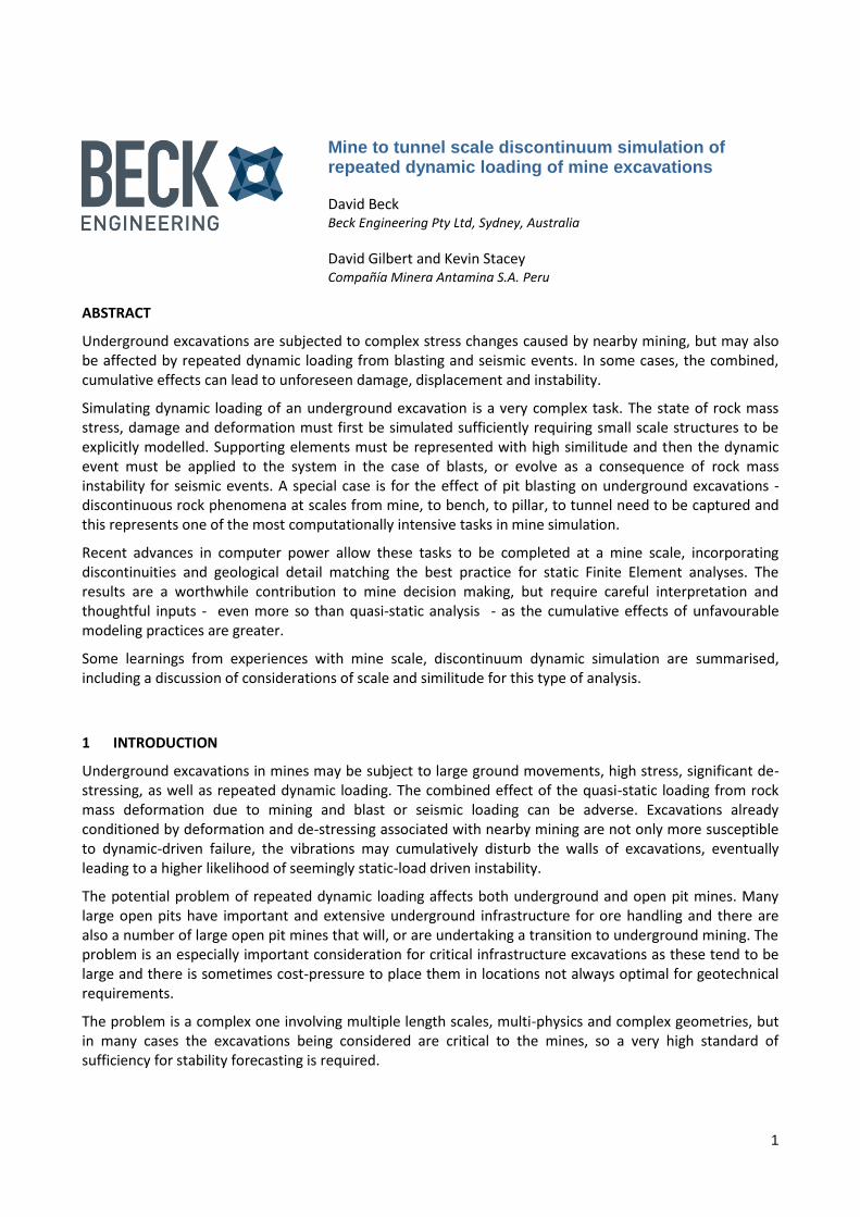
Mine to tunnel scale discontinuum simulation of repeated dynamic loading of mine excavations
David Beck Beck Engineering Pty Ltd, Sydney, Australia
David Gilbert and Kevin Stacey Compañía Minera Antamina S.A. Peru
ABSTRACT
Underground excavations are subjected to complex stress changes caused by nearby mining, but may also be affected by repeated dynamic loading from blasting and seismic events. In some cases, the combined, cumulative effects can lead to unforeseen damage, displacement and instability.
Simulating dynamic loading of an underground excavation is a very complex task. The state of rock mass stress, damage and deformation must first be simulated sufficiently requiring small scale structures to be explicitly modelled. Supporting elements must be represented with high similitude and then the dynamic event must be applied to the system in the case of blasts, or evolve as a consequence of rock mass instability for seismic events. A special case is for the effect of pit blasting on underground excavations - discontinuous rock phenomena at scales from mine, to bench, to pillar, to tunnel need to be captured and this represents one of the most computationally intensive tasks in mine simulation.
Recent advances in computer power allow these tasks to be completed at a mine scale, incorporating discontinuities and geological detail matching the best practice for static Finite Element analyses. The results are a worthwhile contribution to mine decision making, but require careful interpretation and thoughtful inputs - even more so than quasi-static analysis - as the cumulative effects of unfavourable modeling practices are greater.
Some learnings from experiences with mine scale, discontinuum dynamic simulation are summarised, including a discussion of considerations of scale and similitude for this type of analysis.
1 INTRODUCTION
Underground excavations in mines may be subject to large ground movements, high stress, significant de-stressing, as well as repeated dynamic loading. The combined effect of the quasi-static loading from rock mass deformation due to mining and blast or seismic loading can be adverse. Excavations already conditioned by deformation and de-stressing associated with nearby mining are not only more susceptible to dynamic-driven failure, the vibrations may cumulatively disturb the walls of excavations, eventually leading to a higher likelihood of seemingly static-load driven instability.
The potential problem of repeated dynamic loading affects both underground and open pit mines. Many large open pits have important and extensive underground infrastructure for ore handling and there are also a number of large open pit mines that will, or are undertaking a transition to underground mining. The problem is an especially important consideration for critical infrastructure excavations as these tend to be large and there is sometimes cost-pressure to place them in locations not always optimal for geotechnical requirements.
The problem is a complex one involving multiple length scales, multi-physics and complex geometries, but in many cases the excavations being considered are critical to the mines, so a very high standard of sufficiency for stability forecasting is required.

2
Sufficient analysis must consider:
- 3 dimensional geometry
- Appropriate length scale of discontinuities
- Appropriate continuum material models
- Stress path
- Hydro-mechanical interactions, if present
- Blast dynamics, and scale and similitude for dynamic effects
At Antamina Mine, Peru a preliminary study of the effects of future pit induced deformation and blast loading on a conveyor tunnel was undertaken using a detailed series of Explicit, strain softening, dilatant discontinuum Finite Element models. The process made use of multiple parallel computing to incorporate these effects with the greatest fidelity possible given the available field information and other practical limitations. In this paper, a workflow for multi-scale dynamic simulation is described for this pit-tunnel interaction example, but an analogous procedure could be followed for many multi-scale dynamic simulation problems for mines.
2 PROCEDURE
The procedure for the example problem consisted of 2 phases: quasi-static and dynamic. The quasi-static part tests the stability of the slope and rock mass and establishes the cumulative deformation and damage in the slope by considering the equilibrium between stress, strain, strength and structure as the pit is excavated to the pre-blast geometry. The dynamic phase simulates the effects of transient stress waves due to blasting in the deformed slopes. As the pit mining progresses from stage to stage in the quasi-static model, dynamic events are applied at planned blast locations of interest.
2.1 Quasi-static work flow
The purpose of the quasi static workflow is to establish the deformation and damage in the slope and the rock mass surrounding the excavation prior to the blast. These Explicit Finite Element (FE) models are the starting point for any blast simulation and are also used to assess stability of the slope or tunnel. In most cases, existing Explicit FE models sufficient for stability analysis can be re-used for this task.
For the current example, 2 scales of quasi static, hydromechanically coupled, discontinuum, Explicit FE models were used. The largest scale model is global scale, and consists of a global model including all mapped global scale structure and geological domains and necessary excavation steps. In this case quarterly excavation stages were used to properly capture the stress path in the slope. To this global model, a Discrete Fracture Network that matches the tunnel and face mapping was then added to establish the necessary discontinuum response at a sector, or intermediate scale around the area of interest. Properly representing the structural coupling of the area of interest (sector scale) to global scale deformation is essential to simulate realistic slope movements.
The scale of structure needed in the sector scale DFN of the global model depends on the scale of phenomena and mechanisms of expected deformation and damage being investigated. In the example case, structure at a scale intermediate between bench and inter-ramp scale was judged as critical to simulate behaviour of the pit wall and tunnel surrounds.
In the immediate vicinity of the tunnel, the structures are built as mapped so there is good confidence in the geometric representation of these structures. Away from the tunnel, the structures are a statistical representation intended to generate sub-wall scale mechanisms. Thus, the sector-global DFN gives a guide to potential mechanisms and generates more realistic deformation and damage behaviour than a model without these smaller structures, but any explicit local issue at that scale (i.e. an intermediate scale
3
problem at a specific time and particular place due to an individual structure) is representative but not exact.
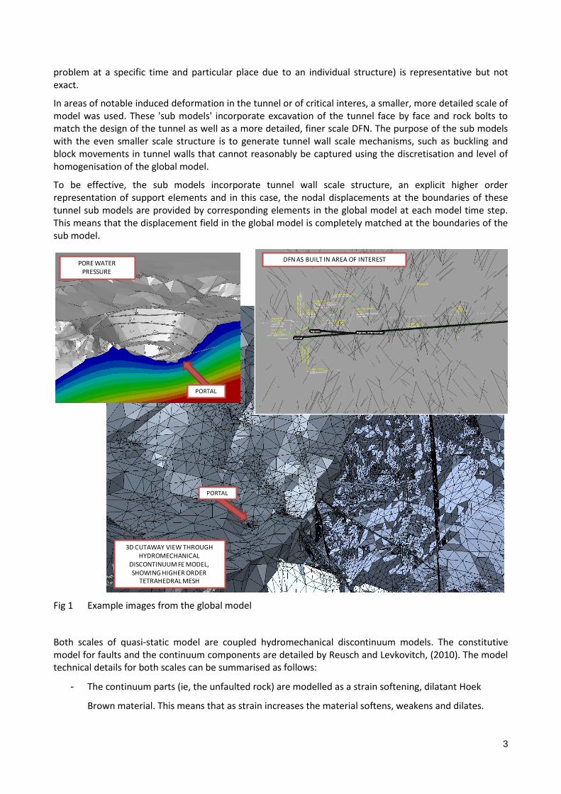
In areas of notable induced deformation in the tunnel or of critical interes, a smaller, more detailed scale of model was used. These 'sub models' incorporate excavation of the tunnel face by face and rock bolts to match the design of the tunnel as well as a more detailed, finer scale DFN. The purpose of the sub models with the even smaller scale structure is to generate tunnel wall scale mechanisms, such as buckling and block movements in tunnel walls that cannot reasonably be captured using the discretisation and level of homogenisation of the global model.
To be effective, the sub models incorporate tunnel wall scale structure, an explicit higher order representation of support elements and in this case, the nodal displacements at the boundaries of these tunnel sub models are provided by corresponding elements in the global model at each model time step. This means that the displacement field in the global model is completely matched at the boundaries of the sub model.
Fig 1 Example images from the global model
Both scales of quasi-static model are coupled hydromechanical discontinuum models. The constitutive model for faults and the continuum components are detailed by Reusch and Levkovitch, (2010). The model technical details for both scales can be summarised as follows:
- The continuum parts (ie, the unfaulted rock) are modelled as a strain softening, dilatant Hoek
Brown material. This means that as strain increases the material softens, weakens and dilates.
PORTAL
PORTAL
3D CUTAWAY VIEW THROUGH HYDROMECHANICAL
DISCONTINUUM FE MODEL, SHOWING HIGHER ORDER
TETRAHEDRAL MESH
PORE WATER PRESSURE
DFN AS BUILT IN AREA OF INTEREST

4
- Discrete structures that are explicitly represented in the models are represented by cohesive
elements, that convert to explicit contact elements after a sufficient amount of strain. This enable
the best features of FE and Discrete element modelling to be utilised.
- In these hydro-mechanical models, conventional equations governing fluid flow and Pore Water
Pressure (PWP) are solved simultaneously (Darcy, 1856) with the equations for deformation and
damage inside 3D, strain softening, dilatant, discontinuum models. The PWP distribution is
calibrated by matching field measurements.
- The pre-mining stress field was established via a series of equilibrium steps, involving erosion and
mountain formation to achieve a sufficient match with measurements.
- The software used was Abaqus Explicit. The key feature is that this is an explicit Finite Element code
able to be run on parallel computers; several other off-the-shelf commercial alternatives are also
viable for this form of analysis.
Example images from the global model are shown in Figure 1, while an example image from a sub model is shown in Figure 2.
Fig 2 Example images from a sub model
Rock mass damage - bolts and fibrecrete not shown. Displacements magnified 10x

5
2.2 Work flow for dynamic simulation
The purpose of the dynamic simulation is to better understand the nature of vibrations induced at the tunnel location by production blasts in the pit and to estimate whether these might be sufficient to result in unacceptable damage. The intent is to understand geometric effects, such as structural channelling of blast wave energy and potential problem areas. Over time, the mine will use the monitoring data to make forecasts, and the purpose of this study is to help frame that longer term effort and start the long term calibration of vibration predictions.
The general outline for execution of the dynamic analysis is as follows:
- A blast is applied to the deformed and displaced global model at a particular point in time, to
capture the global effect of slope deformation, stress, structure and water on the blast waves at
the tunnel location
- The waveforms of displacements at boundary node locations of the tunnel sub models from the
quasi-static calculations are collected from the global model, then applied in their entirety to the
sub models boundary nodes to generate an exact element by element reproduction of the
transient stresses and displacements at the sub model boundaries. The sub model is then run with
these dynamic boundary conditions to generate sub-tunnel scale dynamic effects and to
accumulate the effects of repeated dynamic loading.
Fig 3 Scaled distance and PPV from measured blasts at the mine
y = 2020(d/w1/2)-2.258
0.01
0.1
1
10
100
1000
0.1 1.0 10.0 100.0 1000.0
Vm
ax [m
m/s
ec]
Scaled distance m/kg1/2

6
Fig 4 Example synthetic waveform with PPV of 420mm/sec constructed for application to the envelope around the test blast sites in the global model
- For both scales, the dynamic loads are applied at the correct time in the pit extraction sequence to
ensure that the accumulated damage and deformation in the slope prior to each blast is
represented as well as possible.
A more detailed consideration of the application of the blast wave to the global model is as follows:
- The blast needs to be applied to the global model at the selected pit extraction stage, with the
accumulated levels of deformation and rock mass damage in place throughout the model. This
requires that first, the model be allowed to come to quasi-static hydro-mechanical equilibrium at
the selected extraction stage.
- Next, the blast source needs to be applied to the model at the blast location. For practical reasons
of time and cost for a preliminary exercise, the blast cannot be simulated directly, for instance by
mechanically and explicitly simulating individual holes. Instead, an envelope around a blast location
is constructed and a transient, spherical stress wave approximating that from a multi-delay firing is
applied to the model nodes on this 3d envelope. This large envelope avoids problems of near-field
dynamic effects related to smallness of the source that would complicate the model construction
and physics of wave propagation, for instance that would require extremely small elements at the
blast location or a more complex representation of the blast source. The key compromise is to use
the smallest 'envelope' around the blast location for applying the transient blast induced
displacements that will not cause numerical stability issues or violate requirements of scale and
similitude.

7
Fig 5 Example of particle velocity at an instant in the global model
mm/sec
Higher
Lower
8
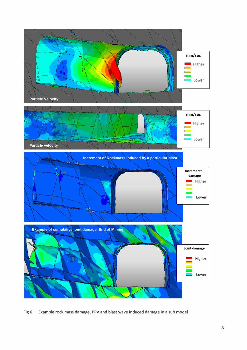
Fig 6 Example rock mass damage, PPV and blast wave induced damage in a sub model
Particle Velocity
Particle velocity
Increment of Rockmass induced by a particular blast
Example of cumulative joint damage, End of Mining
Incremental
damage
Higher
Lower
Joint damage
Higher
Lower
mm/sec
Higher
Lower
mm/sec
Higher
Lower

9
- A discussion of dynamic scale and similitude is beyond the scope of this paper and is very complex
close to a blast source, but briefly, the considerations of scale effects and near-field wave
propagation effects requires that the envelope be much larger than the nodal spacing of the model,
the radius of the envelope is appreciably larger than the blast volume and that the distance
between the 'source' and the area of interest is larger by some factor than the envelope size. For
the current example, the selected envelope radius was 50m, so no blasts closer than 75-100m were
simulated.
- If closer blasts need to be simulated, the wave can be directly applied to the sub model boundaries
but a more detailed description of the source in 3d - probably from direct blast simulation - would
be needed.
- A synthetic blast source for application on this envelope was constructed using measured blast
data as a basis. The intent is to establish the PPV (Peak Particle Velocity) and spectra arising from
the cumulative effects of individual delays that would produce the required PPV at 50m from the
blast centre. For the synthetic blast the following is assumed:
- Max charge weight per delay: 625kg
o The scaled distance relation for the mine was computed from the data of Figure 3. (Vmax =
2020 (d/w1/2)-2.2585 where Vmax is the PPV [m/sec] at a site remote from the blast, d is the
slope distance to the blast [m], w is the total weight of explosives per a minimum delay of
8ms (by convention). With these assumptions, the expected ppv for the envelope at 50m is
420mm/sec. A blast wave with close delays and this ppv was constructed by superimposing
waveforms approximating individual holes/delays as shown in Figure 4. Generally the delay
between individual peaks (corresponding to delays) in the synthetic waveform may be
closer than practised at the mine, but the intent here was to have a reasonable
approximation of the dominant frequency and manipulation of effective delay spacing is
the simplest way to achieve this in a Finite Element model. Future analysis could use close-
measured real blast measurements or direct-explicit simulation of the blast holes to better
match the full spectral characteristic of the blast wave, but this is not a task for a
preliminary scope of work.
- The synthetic waveform was then applied to the global model, and ultimately the sub model as
described above. PPV, PPA and other information was recorded in the global model as a first
reference for review, and the record of transient displacements, cumulative damage and bolt
damage in the sub models was recorded for more detailed consideration.
10
-
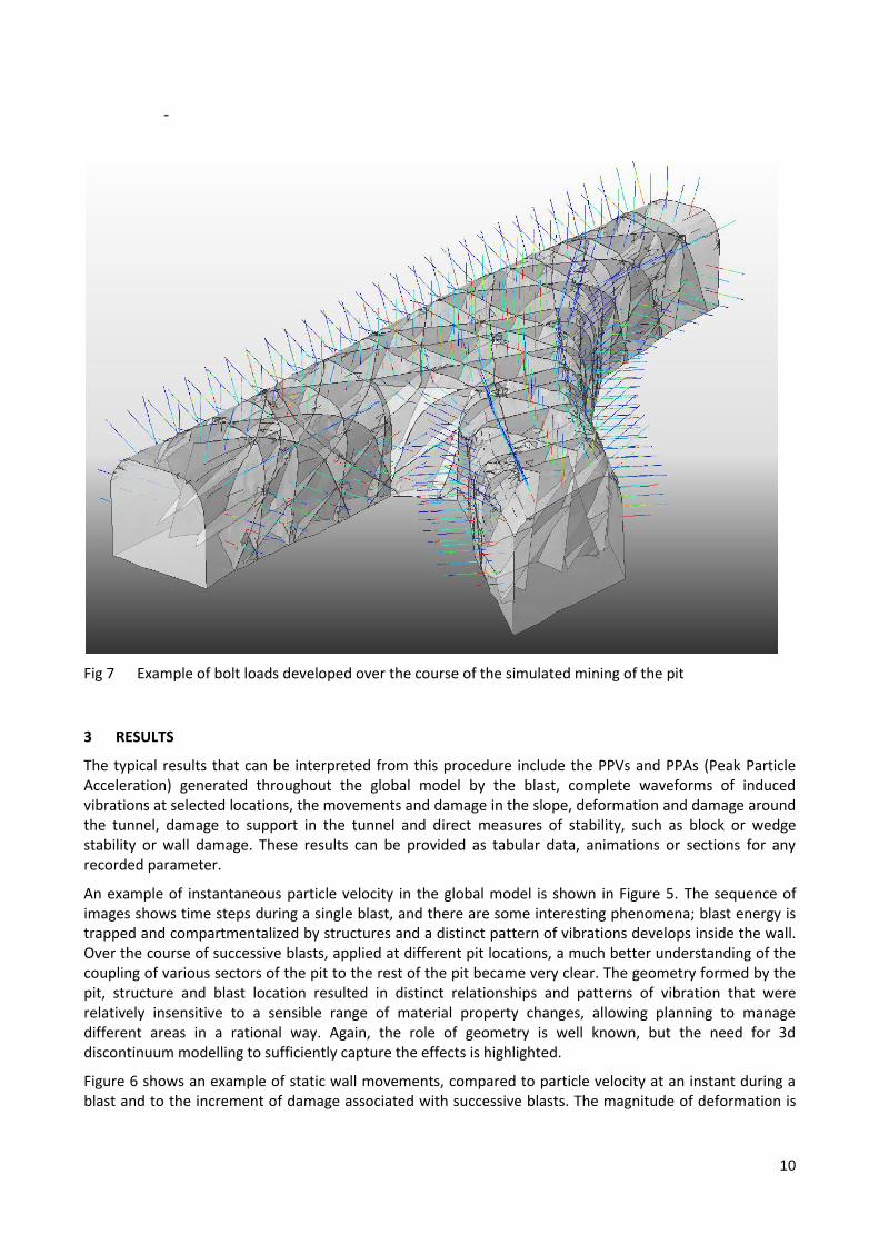
Fig 7 Example of bolt loads developed over the course of the simulated mining of the pit
3 RESULTS
The typical results that can be interpreted from this procedure include the PPVs and PPAs (Peak Particle Acceleration) generated throughout the global model by the blast, complete waveforms of induced vibrations at selected locations, the movements and damage in the slope, deformation and damage around the tunnel, damage to support in the tunnel and direct measures of stability, such as block or wedge stability or wall damage. These results can be provided as tabular data, animations or sections for any recorded parameter.
An example of instantaneous particle velocity in the global model is shown in Figure 5. The sequence of images shows time steps during a single blast, and there are some interesting phenomena; blast energy is trapped and compartmentalized by structures and a distinct pattern of vibrations develops inside the wall. Over the course of successive blasts, applied at different pit locations, a much better understanding of the coupling of various sectors of the pit to the rest of the pit became very clear. The geometry formed by the pit, structure and blast location resulted in distinct relationships and patterns of vibration that were relatively insensitive to a sensible range of material property changes, allowing planning to manage different areas in a rational way. Again, the role of geometry is well known, but the need for 3d discontinuum modelling to sufficiently capture the effects is highlighted.
Figure 6 shows an example of static wall movements, compared to particle velocity at an instant during a blast and to the increment of damage associated with successive blasts. The magnitude of deformation is
11
exaggerated. In this particular location a very minor problem, very easily managed with superficial support is identified, but the mechanism of damage and the mode of the tunnel response is familiar and realistic.
Finally, Figure 7 shows an example of bolt loads developed over the course of the mining in a stable excavation. Transient bolt loads can be plotted for each blast, and the damage is cumulative.
4 CONCLUSIONS
The example simulation shows that realistic, detailed dynamic simulation of mine excavations utilising large quantities of available information is possible. Each part of the procedure is relatively standard and results can be verified at each stage by comparing modelled results to field measurements.
The workflow and technology explained here may prove useful for specifying ground support designs for complex shaped excavations or excavations subjected to dynamic loads in a mining environment, which at the moment is an area of geotechnical engineering of some importance. Empirical guidelines exist but they cannot account well for the geometry of the excavation, effects of structure or repeated loading and are not easily verified using field data.
In the mining context, at present there are no significant technical hurdles preventing adoption of similar analysis practice for analogous problems, with all tools required for the simulation available off-the-shelf and at a cost comparable to traditional analysis. In future, similar simulation should become more commonplace.
The effects of rock bursting or blasting on mine excavations are obvious applications, but a similar procedure could be applied to assess effects of other dynamic sources or explosions on civil infrastructure or for military applications.
5 ACKNOWLEDGEMENTS
The authors wish to acknowledge Compañía Minera Antamina S.A. for permission to publish this paper.
6 REFERENCES
Reusch, F. and Levkovitch, V. 2010. Application of a non-linear confinement sensitive constitutive model to mine scale simulations subject to varying levels of confining stress. Accepted for publication in Eurock 2010. Switzerland.
Darcy, H. 1856. Les Fointaines de la Ville de Dijon. Victor Dalmont, Paris.