mn89 1951383b tracker5100-5500i eng sp po - navman€¦ · operation manual ... changes which could...
TRANSCRIPT

C H A R T P L O T T E R S
NAVMAN
Installation andOperation Manual
www.navman.com
TRACKER 5500, 5500i
5100 and 5100i
TRACKER 5500
TRACKER 5500i
TRACKER 5100i
TRACKER 5100
English ............. 2Español .......... 41Português ......79

2 TRACKER 5100/5100i/5500/5500i Installation and Operation ManualNAVMAN
FCC StatementNote: This equipment has been tested and found to comply with the limits for a ClassB digital device, pursuant to Part 15 of the FCC Rules. These limits are designed toprovide reasonable protection against harmful interference in a normal installation.This equipment generates, uses and can radiate radio frequency energy and, if notinstalled and used in accordance with the instructions, may cause harmful interferenceto radio communications. However, there is no guarantee that interference will notoccur in a particular installation. If this equipment does cause harmful interference toradio or television reception, which can be determined by turning the equipment offand on, the user is encouraged to try to correct the interference by one or more of thefollowing measures:
Reorient or relocate the receiving antenna.Increase the separation between the equipment and receiver.Connect the equipment into an output on a circuit different from that to whichthe receiver is connected.Consult the dealer or an experienced technician for help.A shielded cable must be used when connecting a peripheral to the serial ports.

3TRACKER 5100/5100i/5500/5500i Installation and Operation ManualNAVMAN
Contents1 Introduction ..................................................................................................... 6
1-1 Care ............................................................................................................................ 61-2 Plug-in cards ............................................................................................................... 61-3 Removing and replacing the display unit ...................................................................... 7
2 Basic operation ............................................................................................... 82-1 Turning on and off / auto power ................................................................................... 92-2 The main displays ........................................................................................................ 92-3 Backlight and display contrast ................................................................................... 102-4 Man overboard (MOB) ............................................................................................... 102-5 Alarms ....................................................................................................................... 102-6 Simulate mode ........................................................................................................... 102-7 Navigating ................................................................................................................. 11
3 Chart ............................................................................................................... 123-1 Chart display ............................................................................................................. 12
3-1-1 Chart modes ..................................................................................................... 123-1-2 Latitude and longitude ....................................................................................... 133-1-3 Chart scale ........................................................................................................ 133-1-4 The compass .................................................................................................... 133-1-5 Chart symbols ................................................................................................... 133-1-6 Chart information ............................................................................................... 133-1-7 Find nearby services ......................................................................................... 133-1-8 Change the data display and compass display .................................................. 13
3-2 Distance and bearing calculator ................................................................................. 143-3 Goto .......................................................................................................................... 143-4 Projected course ....................................................................................................... 153-5 Tracks and tracking ................................................................................................... 15
4 Fuel display ................................................................................................... 165 Data display ................................................................................................... 166 Highway display ............................................................................................ 177 Satellites ........................................................................................................ 17
7-1 Satellite display .......................................................................................................... 18
8 Tides display .................................................................................................. 199 Waypoints ...................................................................................................... 20
9-1 Waypoints display ...................................................................................................... 209-2 Managing waypoints .................................................................................................. 20
9-2-1 Creating a new waypoint .................................................................................... 209-2-2 Moving a waypoint ............................................................................................. 219-2-3 Editing a waypoint ............................................................................................. 219-2-4 Displaying a waypoint on the chart ..................................................................... 219-2-5 Deleting a waypoint ........................................................................................... 219-2-6 Deleting all waypoints ........................................................................................ 219-2-7 Changing a waypoint’s data ............................................................................... 21

4 TRACKER 5100/5100i/5500/5500i Installation and Operation ManualNAVMAN
10 Routes .......................................................................................................... 2210-1 Routes display ......................................................................................................... 2210-2 Managing routes ...................................................................................................... 22
10-2-1 Creating a new route ....................................................................................... 2210-2-2 Editing a route ................................................................................................. 2310-2-3 Displaying a route on the chart ........................................................................ 2310-2-4 Deleting a route ............................................................................................... 2310-2-5 Deleting all routes ............................................................................................ 23
10-3 Navigating a route .................................................................................................... 2310-3-1 Starting a route ................................................................................................ 2310-3-2 Skipping a waypoint in a route ......................................................................... 2310-3-3 Cancelling a route ........................................................................................... 23
11 User card display ......................................................................................... 2412 About display ............................................................................................... 2513 Setup menu .................................................................................................. 25
13-1 System setup ........................................................................................................... 2513-2 Chart setup .............................................................................................................. 2713-3 DGPS setup ............................................................................................................ 2813-4 Fuel Setup ............................................................................................................... 2813-5 Track setup ............................................................................................................. 2913-6 Alarms setup ........................................................................................................... 2913-7 Units setup .............................................................................................................. 3013-8 Comms setup .......................................................................................................... 3013-9 Time setup ............................................................................................................... 3013-10 Simulate setup ....................................................................................................... 31
14 Systems of several instruments ................................................................ 3115 Installation ................................................................................................... 32
15-1 What comes with the TRACKER ............................................................................. 3215-2 Options and accessories ......................................................................................... 3215-3 Installation ............................................................................................................... 33
Appendix A - Specifications ............................................................................ 36Appendix B - Troubleshooting ........................................................................ 38Appendix C - Glossary and navigation data .................................................. 39Appendix D - How to contact us ....................................................................119

5TRACKER 5100/5100i/5500/5500i Installation and Operation ManualNAVMAN
It is the owner's sole responsibility to install and use the instrument in a manner that will not causeaccidents, personal injury or property damage. The user of this product is solely responsible for observingsafe boating practices.
Global Positioning System: The Global Positioning System (GPS) is operated by the US governmentwhich is solely responsible for its operation, accuracy and maintenance. The GPS system is subject tochanges which could affect the accuracy and performance of all GPS equipment anywhere in the worldincluding the TRACKER. Whilst the NAVMAN TRACKER is a precision navigation instrument, it can bemisused or misinterpreted, which can result in its use being unsafe. To reduce the risk of misusing ormisinterpreting the TRACKER, the user must read and understand all aspects of this Installation andOperation manual. We also suggest that the user practice all operations using the built in simulatorbefore using the TRACKER at sea.
Electronic Chart: The electronic chart used by the TRACKER is an aid to navigation and is designed tosupplement the use of official government charts not replace them. Only official government chartssupplemented by notices to mariners contain the information required for safe and prudent navigation.Always supplement the information provided by the TRACKER with other plotting sources such asobservations, depth soundings, radar and hand compass bearings. Should the information not agreethen the discrepancy must be resolved before proceeding any further.
Fuel Computer: Fuel economy can alter drastically depending on the boat loading and sea conditions.The fuel computer should not be the sole source of information concerning available fuel onboard andthe electronic information should be supplemented by visual or other checks of the fuel load. This isnecessary due to possible operator induced errors such as forgetting to reset the fuel used when fillingthe tank, running the engine with the fuel computer not switched on or other operator controlled actionsthat may render the device inaccurate. Always ensure that adequate fuel is carried onboard for the intendedtrip plus a reserve to allow for unforeseen circumstances.
NAVMAN NZ LIMITED DISCLAIMS ALL LIABILITY FOR ANY USE OF THIS PRODUCT IN A WAY THATMAY CAUSE ACCIDENTS, DAMAGE OR THAT MAY VIOLATE THE LAW.
Governing Language: This statement, any instruction manuals, user guides and other informationrelating to the product (Documentation) may be translated to, or has been translated from, another language(Translation). In the event of any conflict between any Translation of the Documentation, the Englishlanguage version of the Documentation will be the official version of the Documentation.
This manual represents the TRACKER as at the time of printing. Navman NZ Limited reserves the rightto make changes to specifications without notice.
Copyright © 2002 Navman NZ Limited, New Zealand, all rights reserved. NAVMAN is a registered trademarkof Navman NZ Limited.
Important

6 TRACKER 5100/5100i/5500/5500i Installation and Operation ManualNAVMAN
1-2 Plug-in cards
1 IntroductionTRACKER chartplottersNAVMAN’s TRACKER chartplotters are compact,ruggedly built, highly integrated navigation instruments.They have been designed to be easy to use. Complexnavigation functions can be performed with a few keypresses, taking the hard work out of navigation.
This manual covers these NAVMAN chartplotters:TRACKER 5500
Colour display, external GPS antenna.TRACKER 5500i
Colour display, internal GPS antenna.TRACKER 5100
Greyscale display, external GPS antenna.TRACKER 5100i
Greyscale display, internal GPS antenna.The TRACKER has a built-in chart of the world,suitable for route planning and general interest. Tosee chart details for a region, plug in a C-MAP™ chartcard (an electronic chart).
The TRACKER receives information from the GPSsystem and displays the boat’s position and speed.
The TRACKER can navigate to a point or can navigatealong a route. When the boat is navigating to one ofthese points, the TRACKER displays courseinformation for the helmsman to follow.
The TRACKER can control an autopilot and candisplay depth information from a depth sounder. Withan optional fuel kit, the TRACKER becomes asophisticated yet easy to use fuel computer. Navigationdata can be saved to a plug-in user card so that it canbe easily transferred to another NAVMAN chartplotter.
The TRACKER is part of the NAVMAN family ofinstruments, which includes instruments for speed,depth, wind and repeaters. These instruments can beconnected together to form an integrated data system(see section 14).
For maximum benefit, please read this manualcarefully before installing and using the unit. Specialterms are explained in appendix C.
Cleaning and maintenanceCaution should be used when cleaning the TRACKER,and especially the screen of the TRACKER. Only usea clean sponge or chamois soaked in fresh water andmild detergent. Never use a dry cloth as this may dragdried salt crystals across the screen resulting inscratching. Do not use any form of abrasive cleaner,solvent, petrol or other chemical cleaner.
Push the dust cover over the display when theTRACKER is turned off.
1-1 CarePlug-in cardsHandle plug-in cards carefully. Keep them in theirprotective cases when not plugged into the TRACKER.
If a card gets dirty or wet, clean it with a damp clothor mild detergent.
Keep the card holder in place in the display unit at alltimes to prevent moisture from entering the cardcompartment.
The TRACKER can use two kinds of plug-in cards:
C-MAP™ chart card have chart details requiredfor navigating in a particular region. When a chartcard is plugged in, the extra details automaticallyappear on the TRACKER’s chart display.
C-MAP™ user cards are used to store navigationdata. Each user card expands the TRACKER’smemory and allows the data to be transferred toanother TRACKER easily (see section 11).
When a card is inserted or removed it does not matterif the TRACKER is turned on or off.

7TRACKER 5100/5100i/5500/5500i Installation and Operation ManualNAVMAN
1-3 Removing and replacing the display unitIf the display unit is bracket mounted then the displayunit can easily be removed and replaced for securityor protection.
Removing the display unit:1 Turn the TRACKER off by holding until the
display turns off.2 Push the dust cover over the display unit.3 Hold the display unit with one hand. Loosen
the knob on the mounting bracket and carefullylift the unit off the mounting bracket.
4 The display unit has some cables plugged intothe back.Unplug each black plug by turning the lockingcollar a quarter turn anticlockwise and pullingthe plug out.If there is a gold plug, unscrew the lockingcollar anticlockwise and pull the plug out.
5 Push the attached dust covers over theexposed ends of the plugs to protect them.
6 Store the display unit in a safe place, such asthe optional NAVMAN carry bag.
Replacing the display unit1 Remove the dust covers from the plugs. Plug
the black plugs into their sockets on the backof the display unit:
Match the colour on the end of the plug tothe colour of the nut on the socket.Hold the plug against the socket and rotatethe plug until it slides into the socket.Lock the plug in place by pushing thelocking collar towards the socket andturning it a quarter turn clockwise.
Nothing will be damaged if a cable is pluggedinto the wrong socket by mistake.
2 If the unit has a gold plug:Plug it into its socket on the back of thedisplay unit.Hand tighten the locking collar clockwise -do not overtighten.
3 Hold the display unit in place on the mountingbracket shaft, with the rubber washer clampedbetween the bracket and the display unit.
4 Adjust the tilt and rotation of the display forbest viewing and hand tighten the knob on themounting bracket. Remove the dust cover.
Pull card holder out ofTRACKER.
Pull any card out of holder.Put card in case.
Card
Holder
Gold contacts under here
Push new card into holder.Ensure the gold contactsare on the outer edge andunderneath (see above).Keep the card’s case.
Push card holder fully intoTRACKER.
Changing the plug-in card
431 2
Warning: Keep the holder in place in the TRACKER at all times to preventmoisture from entering card compartment.

8 TRACKER 5100/5100i/5500/5500i Installation and Operation ManualNAVMAN
2 Basic operation
Overview of the keysESC Go back to an earlier menu or display. Any changes
are ignored.
DISP Show a menu of the main TRACKER displays. To goto a display, select it from the menu (see section 2-2).
, , , Cursor keys, to move the cursor or theselection highlight.
MENU Show a menu of the options for the current display.Press MENU again to display the setup menu (seesection 13).
ENT Start an action or accept a change.
Zoom in and display a smaller area of the chart inmore detail.
Zoom out and display a bigger area in less detail.
Create an instant waypoint at the boat position (seesection 9-2-1).
Man overboard (MOB, see section 2-4).
Turn TRACKER on and off (see section 2-1); adjust thedisplay (see section 2-3).
KeysIn this manual:
Press means to push the key for less than a second.
Hold means to hold the key down.
The internal beeper beeps when a key is pressed (to disableor enable the beep, see section 13-1).
To select an item in a menuThe TRACKER is operated by selecting items from menusshown on the display.
1 Press or to move the highlight to the item.
2 Press ENT or to select the item.
Change a number or wordTo change a number or word on the display:
1 Press or to move the highlight to the digit orletter to change.
Press or to change the digit or letter.
2 Repeat the above step to change any other digits orletters.
3 Press ENT to accept the change.

9TRACKER 5100/5100i/5500/5500i Installation and Operation ManualNAVMAN
2-1 Turning on and off / auto powerAuto powerIf the TRACKER is wired for auto power (see section15-3), then the TRACKER automatically turns on andoff with the boat power, and can not be turned on oroff manually.
Turning on manuallyIf the TRACKER is not wired for auto power, turn theunit on by pressing .
StartupAfter the TRACKER has been turned on:
1 The unit displays a title display for a fewseconds, then beeps again and displays anavigation warning.
2 If necessary, adjust the display to be easy toread (see section 2-3).
Read the warning and press ENT.
3 The satellite display is shown.
Either wait for the GPS receiver to start upand the status to change from ‘acquiring’ to‘GPS fix’ (see section 7).
Or press ESC.
4 The TRACKER chart is displayed (see section 3).
Turning off manuallyIf the TRACKER is not wired for auto power, turn theunit off by holding down until the display turns off.
After you have turned the TRACKER on, it showsthe satellite display until the GPS receiver gets a GPSfix, then displays the Chart. The Chart is the displaythat you will normally use for navigation.
2-2 The main displays
Fuel (fuel computer) Section 4
Waypoints Section 9
Tides (tide chart) Section 8
Satellite (GPS data) Section 7
Highway (boat path) Section 6
Data (numeric data) Section 5
User card Section 11
Routes Section 10
About Section 12
The main displays See:Display menu
Chart
Fuel
Data
Highway
Satellite
Tides
Waypoints
Routes
User C-card
About
Press ESC toreturn tochart display
To use one of the other main displays, press DISPfor the display menu and select a display to use.
To return to the chart display, press ESC.
Press DISP fordisplay menu
To select a display:
i press or tohighlight the display
ii press ENT to go tothe display
Chart (navigation) Section 3

10 TRACKER 5100/5100i/5500/5500i Installation and Operation ManualNAVMAN
2-6 Simulate modeSimulate mode allows a user to become familiar withthe TRACKER off the water. In Simulate mode, thedata from the GPS receiver and other sensors isignored and the TRACKER generates this datainternally to simulate the movement of the boat.Otherwise, the TRACKER functions normally.
To see if the TRACKER is in Simulate mode, pressDISP and select Satellite. If it is in Simulate mode,then it shows Simulate at the top left of the display.
To start and stop Simulate mode, (see section 13-10).
Warning: Never have Simulate mode on whenthe TRACKER is navigating on the water.
2-5 AlarmsWhen the TRACKER detects an alarm condition, itdisplays a warning message on the display, theinternal beeper sounds and any external beepers orlights operate.
Press ESC to clear the alarm. The alarm will soundagain if the alarm condition occurs again.
The TRACKER has five user settable alarms: arrivalradius, anchor, XTE, danger and low fuel (see section13-6).
In addition, the TRACKER has a fixed alarm for lossof GPS/DGPS fix.
The MOB feature saves the boat’s position and thennavigates back to this point. To do this:
1 Press .
The TRACKER beeps four times and storesthe boat’s position as a waypoint called MOB.
2 The TRACKER changes to the chart display,with the MOB waypoint at the centre of thechart.
The chart zooms in for accurate navigation. Ifthe chart can not show the required smallscale, the TRACKER changes to plotter mode(a white display with crosshatching, and nochart details, see section 13-2).
3 If the autopilot output is off (see section 13-8)the TRACKER immediately starts navigatingback to the MOB waypoint.
If the autopilot output is on, the TRACKERasks if the autopilot is active. Select:
2-4 Man overboard (MOB)No: The TRACKER immediately starts
navigating back to the MOB waypoint.
Yes: The TRACKER asks if the boat is to go tothe MOB waypoint. Select:
Yes: to immediately start navigating tothe MOB waypoint.
Warning: This might result in asudden and dangerous turn.
No: to allow time to disengage theautopilot; then use Goto to navigateback to the MOB waypoint(see section 3-3) .
To cancel MOB or set another MOB.1 Press again to display a menu.
2 Select an option from the menu.
Tip: The MOB waypoint remains on the chart afterthe MOB has been cancelled. To delete the MOBwaypoint, (see section 9-2-5).
2-3 Backlight and display contrast1 Press briefly to show the display controls.
2 The display and keys are backlit, with sixteenbrightness levels.
To change the backlight, press (dimmer) or (brighter)
3 To change the display contrast (TRACKER5100 or 5100i):
i Press to choose Contrast.
ii Press or to adjust the contrast.
4 Press ENT to accept the new values.

11TRACKER 5100/5100i/5500/5500i Installation and Operation ManualNAVMAN
2-7 NavigatingThe TRACKER has two ways of navigating, goingstraight to a point or following a route.
Enter waypoints at points of interest before startingto navigate (see section 9-2-1).
Tip: create a waypoint at the start of the trip tonavigate back to.
Goto: Going straight to a pointThe TRACKER can navigate straight to a waypointor to any arbitrary point:
1 In the chart display, move the cursor to thedestination point to navigate to (see section 3-1-1).
2 Start navigating using the Goto function fromthe chart menu (see section 3-3).
The chart, data and highway displays shownavigation data. The chart shows:
The boat position .
The destination point marked with a circle.
The boat’s plotted course to thedestination.
Two CDI lines, parallel to the boat’s plottedcourse (see appendix C, CDI).
If the TRACKER is connected to an autopilot,the TRACKER will send data to the autopilot tosteer the boat to the destination.
If the XTE alarm is enabled, an alarm willsound if the boat deviates too much from itsintended course (to set the XTE alarm, seesection 13-6).
3 If the arrival radius alarm is enabled, then,when the boat comes within the arrival radiusof the destination, an alarm will sound to showthat the boat has reached the destination (toset the arrival radius alarm, see section 13-6).
4 To stop the Goto, (see section 3-3).
Following a routeA route is a list of waypoints that the boat can follow(see section 10).
1 To create waypoints before creating the route,use the waypoints display (see section 9-2-1).
2 To create a route, go to the chart or routesdisplay (see section 10-2-1).
3 To start the route, see section (10-3-1).
The chart, data and highway displays shownavigation data. The chart shows:
The boat position .
The waypoint at the end of the current legmarked with a circle.
The boat’s plotted course along the leg.
Two CDI lines, parallel to the boat’s plottedcourse (see appendix C, CDI).
If the TRACKER is connected to an autopilot,the TRACKER will send data to the autopilot tosteer the boat to the destination.
If the XTE alarm is enabled, an alarm willsound if the boat deviates too much from itsintended course (see section 13-6).
If the arrival radius alarm is enabled, then,when the boat comes within the arrival radiusof the waypoint at the end of the current leg, analarm will sound (to set the arrival radiusalarm, see section 13-6).
4 The TRACKER stops navigating to thewaypoint at the end of the current leg andstarts the next leg of the route:
a When the boat comes within 0.025 nm ofthe waypoint.
b Or when the boat passes the waypoint.
c Or if the waypoint is skipped (see section10-3-2).
5 When the boat has reached the final waypoint,or to stop the boat following the route at anytime, cancel the route (see section 10-3-3).

12 TRACKER 5100/5100i/5500/5500i Installation and Operation ManualNAVMAN
3 Chart
3-1-1 Chart modesThe Chart has two modes, centre on boat mode andcursor mode. These are explained below.Centre on boat modeTo switch to centre on boat mode in the chart display,press ESC. The boat is at the centre of the chart.As the boat moves through the water, the chartautomatically scrolls to keep the boat in the centreof the chart. The cursor (see below) is turned off.Cursor mode
The keys , , and are called cursor keys.To switch to cursor mode in the chart display, holddown a cursor key. The cursor appears and movesaway from the boat:
Press the key which points in the direction thatthe cursor will move, for example press tomove the cursor down.
Press midway between two of the cursor keysto make the cursor move diagonally.Hold a cursor key down to make the cursormove continuously across the display.
In Cursor mode:The distance (+RNG) and bearing (+BRG) ofthe cursor from the boat are displayed at thebottom, left corner of the display.The chart does not scroll as the boat moves.If the cursor reaches the edge of the display,the chart will scroll.
For example, hold down to move the cursorto the right side of the display and the chart willscroll to the left.
The chart. To change thetypes of informationdisplayed, (see section13-2).
Compass display(see section 3-1-4).To turn the compass offor on, see section 3-1-8.
Boat course and CDI lines(see appendix C, CDI)
Boat is going to thewaypoint called FISH06.
Data display. To turn thedata off or on or to changewhat data is displayed, seesection 3-1-8.
Boat position(see section 3-1-1)
Boat track(see section 3-5)
Typical waypoint(see section 9).
A typical chart display shows:
Distance and bearing ofcursor from boat.
The cursor(see section 3-1-1).
3-1 Chart display
The chart display is the most important of the TRACKER’s displays, showing the chart, the boat’s positionand course, and navigation data.
Sea
Land
Chart is in cursor mode, press ESC to return tocentre on boat mode (see section 3-1-1)

13TRACKER 5100/5100i/5500/5500i Installation and Operation ManualNAVMAN
3-1-2 Latitude and longitudeLatitude and longitude can be displayed at the top ofthe chart. Normally the position is the boat’s position,and the latitude has a boat symbol to show this:
If the cursor has been moved in the last ten seconds,then the position is the cursor’s position, and thelatitude has a cursor symbol to show this:
Warning: When reading the boat position,make sure the position is not the cursor position.
3-1-3 Chart scalePress to zoom in and display a smaller area ofthe chart in more detail. Press to zoom out anddisplay a bigger area in less detail.
The chart scale can be displayed (e.g. scale = 8 nm,see below). The scale is the vertical distance acrossthe currently visible chart area. For example if thescale is 8 nm then a portion of chart eight nauticalmiles high is currently displayed.
3-1-4 The compassA compass can be displayed at the top of the chart(see section 3-1-8).
When the boat is navigating to a point, the compassshows the bearing to the destination (BRG) in themiddle and the boat’s course over ground (COG),for example here BRG is 4° and COG is 12°:
Otherwise the compass shows the boat’s COG inthe middle, for example here COG is 12°:
3-1-5 Chart symbols
The chart will show symbols, such as waypoints andchart symbols. When the cursor is placed over asymbol for at least two seconds, a data windowappears at the bottom left of the display withinformation about the symbol.
3-1-6 Chart informationTo see stored data about a point on the chart (forexample, a chart symbol):
1 Move the cursor to that point on the chart.2 Press MENU and select Chart info.3 A menu of objects is displayed:
i Select an object to display.ii Press ESC to return to the menu. Select
other objects.iii Finally, press ESC to return to the chart.
3-1-7 Find nearby servicesTo find and display nearby services:
1 To see services near the boat’s position, pressESC to switch to centre on boat mode. To seeservices near a different point, move the cursorto that point on the chart.
2 Press MENU and select Find.3 Select the type of service. There are three
types of service:Ports
A list of ports is displayed. Select the portto display.To search for a port:i Press MENU and select Find.ii Enter some or all of the letters of the
port name. Press ENT.Port services
i Select the type of service to find.ii A list of places with this service are
displayed. Select the place to display.Tide stations
A list of tide stations is displayed. Selectthe station to display. The chart redrawswith the tide station centred. To nowdisplay a tide chart (see section 8) for thestation:i Press MENU and select Chart info.ii Select Tide height.
3-1-8 Change the data display andcompass displayNumeric data and a compass can be displayed atthe top of the chart display. To change these:1 Press MENU and select Data header.2 To turn the data display off or on:
i Select Data.ii Select Off or On.
3 To choose the size of the numbers:i Select Size.ii Select:
Small: displays three fields per line andup to four lines.Large: displays two fields per line andup to four lines.
BRG (red) COG
COG
Minutes, to 3 decimal places(about 2 m (6 ft) resolution)
Degrees
36° 29.637' S 175° 09.165' E
Latitude
Longitude
+ 36° 29.684' S 175° 09.201' E

14 TRACKER 5100/5100i/5500/5500i Installation and Operation ManualNAVMAN
3-2 Distance and bearing calculatorThe distance and bearing calculator can plot a courseof one or several legs and to show the bearing and lengthof each leg, as well as the total distance along the course.The completed course can be converted into a route.
To use the distance and bearing calculator:
1 Press ESC until the chart display is displayed.Press MENU and select Distance.
2 Move the cursor to the start of the first leg. Itdoes not matter if this point is a waypoint ornot. Press ENT.
3 To add a leg to the course, move the cursor tothe end of the leg. It does not matter if thispoint is a waypoint or not. The display shows
4 To change the data display:i Select Data setup.ii Change a data field:
a Press the cursor keys to highlight thefield.
b Press ENT to display a menu of thedata that can be shown in the field.
c Select the data to show in the field;select None to leave the field empty.
iii Repeat the above step to set the other datafields. Press ESC.
Tip: If less than four lines are used, thenumeric data will take up less of the chart area.
5 To turn the compass display off or on:i Select Compass.ii Select Off or On.
6 Finally, press ESC to return to the chart display.
3-3 GotoGoto is a simple way of navigating straight to onepoint.
To start the Goto1 Choose the point to go to:
To go to a waypoint or to any point on thechart:i Press ESC until the chart display is
displayed.ii Move the cursor to the destination.iii Press MENU and select Goto.To go to a waypoint from the waypointsdisplay:i Press DISP and select Waypoints.
ii Press or to highlight thedestination waypoint.
iii Press MENU and select Goto.
Warning: Make sure the course does not passover land or dangerous waters.2 The TRACKER starts navigating to the
destination (see section 2-7). The chart shows:The destination point marked with a circle.The boat’s plotted course to thedestination.Two CDI lines, parallel to the boat’s plottedcourse (see appendix C, CDI).
To cancel a Goto1 Press ESC until the chart display is displayed.
2 Press MENU and select Cancel goto.
the bearing and length of the leg, as well asthe total distance along the course. Press ENT.
4 To remove the last leg from the course, pressMENU and select Remove.
5 Repeat the above two steps to enter the wholecourse.
6 To save the new course as a route, pressMENU and select Save. This also saves anynew points on the course as new waypoints,with default names. If necessary, edit the routelater (see section 10-2-2) and edit any newwaypoints later (see section 9-2-3).
7 Finally, press ESC to return to the chart display.
15TRACKER 5100/5100i/5500/5500i Installation and Operation ManualNAVMAN
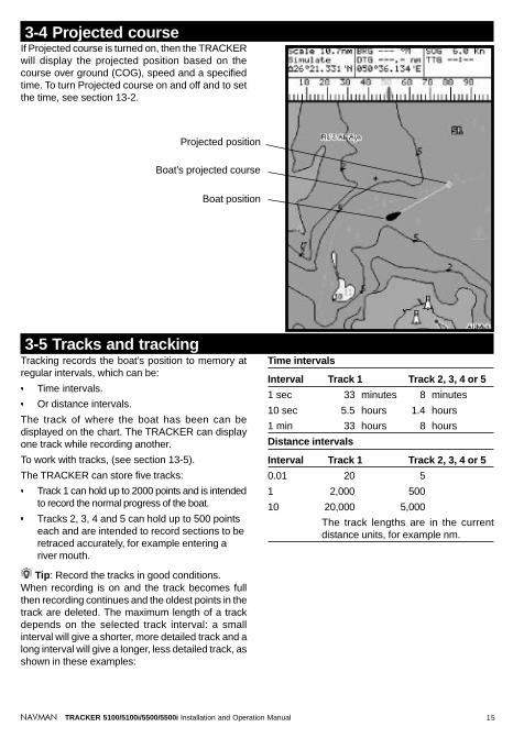
If Projected course is turned on, then the TRACKERwill display the projected position based on thecourse over ground (COG), speed and a specifiedtime. To turn Projected course on and off and to setthe time, see section 13-2.
3-4 Projected course
Tracking records the boat’s position to memory atregular intervals, which can be:
Time intervals.
Or distance intervals.
The track of where the boat has been can bedisplayed on the chart. The TRACKER can displayone track while recording another.
To work with tracks, (see section 13-5).
The TRACKER can store five tracks:
Track 1 can hold up to 2000 points and is intendedto record the normal progress of the boat.
Tracks 2, 3, 4 and 5 can hold up to 500 pointseach and are intended to record sections to beretraced accurately, for example entering ariver mouth.
Tip: Record the tracks in good conditions.When recording is on and the track becomes fullthen recording continues and the oldest points in thetrack are deleted. The maximum length of a trackdepends on the selected track interval: a smallinterval will give a shorter, more detailed track and along interval will give a longer, less detailed track, asshown in these examples:
3-5 Tracks and trackingTime intervals
Interval Track 1 Track 2, 3, 4 or 5
1 sec 33 minutes 8 minutes
10 sec 5.5 hours 1.4 hours
1 min 33 hours 8 hours
Distance intervals
Interval Track 1 Track 2, 3, 4 or 5
0.01 20 5
1 2,000 500
10 20,000 5,000
The track lengths are in the currentdistance units, for example nm.
Boat’s projected course
Boat position
Projected position

16 TRACKER 5100/5100i/5500/5500i Installation and Operation ManualNAVMAN
To use the fuel display, the optional fuel kit must beinstalled and the fuel data set up (see section 13-4).
To go to the fuel display, press DISP and select Fuel.
The fuel display shows:Used: The total fuel used since it was reset to 0 bythe Clear Used command (see section 13-4).
Remaining: The amount of fuel remaining in the fueltank(s).
Flow: The fuel consumption. For twin engineinstallations, the fuel flow for each engine is shownseparately. This is useful for checking that bothengines are under the same load.
Economy: The distance travelled per unit of fuelused. The units are set by the units selected for speedand fuel. Adjust throttle and trim for best economy.The bigger the number the better the economy.
Speed: Boat speed over ground.
Range: The estimated distance that the boat is ableto travel, based on fuel remaining and current fuelconsumption.
4 Fuel display
The data display has eight large numeric data fields,four lines with two fields per line.
To go to the data display, press DISP and select Data.
Change what data is displayed1 Press MENU and select Data setup.
2 Change a data field:
i Press the cursor keys to highlight the field.
ii Press ENT to display a menu of the datathat can be shown in the field.
iii Select the data to show in the field; selectNone to leave the field empty.
3 Repeat the above step to change other fields.
4 Finally, press ESC to return to the datadisplay.
5 Data display
Warnings:Fuel economy can change drastically depending on boat loading and sea conditions. Alwayscarry adequate fuel for the journey plus a sufficient reserve.
Each time fuel is added or removed use the fuel setup menu (see section 13-4) to record thefuel or else fuel remaining and the low fuel alarm will be meaningless!

17TRACKER 5100/5100i/5500/5500i Installation and Operation ManualNAVMAN
6 Highway displayThe highway display has a bird’s eye view of theboat’s course to a destination:
To go to the highway display, press DISP and selectHighway.
Warning: The highway display does not showland, dangerous waters or chart symbols.
CDI lines, parallel to the boat’s plotted course(see appendix C, CDI). The CDI lines are like a highwayover the water where the boat will move.
Six numeric data fields.To change what data is displayed, see below.
Boat position is at the bottom, centre of the display.CDI scale
Boat’s plotted course to destination.
The highway display shows:
Destination waypoint.
Change the numeric data display1 In the highway display, press MENU and select
Data setup.2 Change a data field:
i Press the cursor keys to highlight the field.ii Press ENT to display a menu of the data
that can be shown in the field.
iii Select the data to show in the field; selectNone to leave the field empty.
3 Repeat the above step to change other fields.4 Finally, press ESC to return to the highway
display.
GPS worldwide navigationThe US Government operates the GPS system. Twenty-four satellites orbit the earth and broadcast position andtime signals. The positions of these satellites areconstantly changing. The GPS receiver analyses thesignals from the closest satellites and calculates exactlywhere it is on earth. This is called the GPS position.
The accuracy of the GPS position is typically better than10 m (33 ft) for 95% of the time. A GPS antenna canreceive signals from the GPS satellites when it is almostanywhere on earth.
GPS antennasTRACKERs 5500i and 5100i have built in GPS antennas;TRACKERs 5500 and 5100 are usually connected tothe external GPS antenna supplied. All TRACKERs havea sensitive 12-channel receiver built in. The receivertracks signals from all satellites visible above the horizonand uses measurements from all satellites more than5° above the horizon to calculate the position.
7 SatellitesDGPSA DGPS system uses correction signals to remove someof the errors in the GPS position. The TRACKER canuse one of two types of DGPS system:
WAAS and EGNOS DGPSWAAS and EGNOS are two satellite based DGPSsystems. The correction signals are broadcast bysatellites and are received by the TRACKER’sstandard GPS antenna. The accuracy of thecorrected GPS position is typically better than 5 m(16 ft) for 95% of the time.
WAAS covers all of the USA and most of Canada.EGNOS will cover most of Western Europe whenit becomes operational about the end of 2003. Toenable WAAS and EGNOS DGPS, (seesection 13-3).
Differential beacon DGPSDifferential beacons are land based radiotransmitters that broadcast correction signals

18 TRACKER 5100/5100i/5500/5500i Installation and Operation ManualNAVMAN
that can be received by a special receiver on theboat. Differential beacons are usually onlyinstalled near ports and important waterways,and each beacon has a limited range. Theaccuracy of the corrected GPS position istypically better than 2 to 5 m (6 to 16 ft).
To use differential beacon DGPS, the TRACKERmust be installed with an external DGPS antenna,such as the NAVMAN DGPS 1 (see section 15-3).
StartupEach time a GPS receiver is turned on, it normally takesabout 50 seconds before it outputs the first position.Under some circumstances it will take up to two minutesor longer.
The satellite display has information about the GPSsatellites and GPS position.
To go to the satellite display, press DISP and selectSatellite.
7-1 Satellite display
Time & date from GPSsatellites. Time is local time(UTC (GMT) plus localoffset, see section 13-9).
Boat position.
HDOP: The error in theGPS position caused bysatellite geometry. A lowvalue indicates a moreprecise fix, a high value aless precise fix.
Status of GPS antenna, for example Acquiring, GPS fix, NoGPS. If the unit is in Simulate mode it displays Simulate (seesection 2-6).
Positions of visible GPSsatellites:
Outer circle is horizon
Inner circle is 45°elevation
Centre is directly above
North is at top ofdisplay
If the boat is moving, COGis a line from centre.
Signal strengths of up totwelve visible GPSsatellites. The higher thebar the stronger the signal.
The satellite display shows:
When the TRACKER is turned on, the satellitedisplay is shown automatically while the GPSantenna starts up.

19TRACKER 5100/5100i/5500/5500i Installation and Operation ManualNAVMAN
8 Tides displayThe tides display shows tide information at a tidestation for the selected date.
To go to the tides display for the tide station nearestto the boat, press DISP and select Tides.
To go to the tides display for any tide station:
1 From the chart display, press MENU andselect Find.
2 Select Tide stations.
3 A list of tide stations are displayed. Select thetide station to display. The chart redraws withthe tide station centred.
Moon phase for moon atthe current time on thechosen date.
Height and time of highest high water andlowest low water on tide chart.
Tide station nameDistance from boat
Tide chart
Current timeChosen date for display
Times on selected date.
Tide height cursor. Press
or to move cursorup and down. Height ofcursor.
Time cursor.Press or to move
cursor sideways.Time of cursor
Tide height at that time.
The tides display shows data for the chosen date:
4 Press MENU and select Chart info.
5 Select Tide height.
Choosing the date of the tide chart1 Press MENU.
2 Select Today, Next day or Prev day.
To choose a different date from these, selectSet date, edit the date, press ENT.
Tide height
Time of day, 0 to 24 hrs
Night
Dawn
Day
Night
Dusk
Day

20 TRACKER 5100/5100i/5500/5500i Installation and Operation ManualNAVMAN
To go to the waypoints display, press DISP and selectWaypoints (see right).
The waypoints display is a list of the waypoints thathave been entered, each with waypoint symbol,name, latitude and longitude, distance and bearingfrom the boat, type and display option.
9-2 Managing waypoints Warning: Do not create a navigation waypoint
on land or in dangerous water.
9-2-1 Creating a new waypointCreating a new waypoint from any display
Press . A new waypoint is created at the boatposition with the default name and data. Tochange the default data, (see section 9-2-3).
Creating and editing a new waypoint from thechart display1 To create a waypoint at the boat position, press
ESC to switch the chart to centre on boatmode (or press , see above).Or, to create a waypoint at a different point,move the cursor to that point on the chart.
2 Press MENU and select New waypoint.3 A new waypoint, with the default name and
data is created.
9 Waypoints
9-1 Waypoints display
A waypoint is a position of interest that is saved bythe TRACKER, for example a fishing spot or a pointon a route. The TRACKER can have up to 500waypoints. A waypoint can be created, changed ordeleted. A waypoint has:
A name (up to eight characters).
An icon showing what kind of waypoint it is.The available icons are:
A position.
A colour (TRACKER 5500, 5500i) for thewaypoint symbol and name on the chart.
A type:
Normal: A normal waypoint can benavigated to or included in a route.
Danger: A danger waypoint is a point toavoid. If the boat comes within the dangerradius of a danger waypoint the unit cansound an alarm (see section 13-6).
A display option:
Controls how the waypoint is displayed whenthe Waypoints setup option is set to Selected(see section 13-2):
Off: The waypoint is not displayed.
Icon: The waypoint icon is displayed.
I+N (Icon and Name): The waypoint iconand name are displayed.
If there are many waypoints, use this feature toselect which waypoints are displayed on thechart.
Note: the other choices for the “Waypoints”setup option are “Hide all” (no waypoints aredisplayed on the chart) and “Show all” (all thewaypoints are displayed on the chart) (seesection 13-2).

21TRACKER 5100/5100i/5500/5500i Installation and Operation ManualNAVMAN
4 Change the waypoint data if necessary (seesection 9-2-7). Select Save.
Creating a new waypoint from the waypoints display1 In the waypoints display, press MENU and
select Create.2 A new waypoint, with a default name and data,
is created at the boat position.3 Change the waypoint data if necessary (see
section 9-2-7). Select Save.Note: Waypoints can also be created when a routeis created (see section 10-2-1).
9-2-2 Moving a waypointMoving a waypoint from the chart display1 In the chart display, move the cursor to the
waypoint to move.2 Press MENU and select Move.3 Move the cursor to the new position and
press ENT.
Moving a waypoint from the waypoints displayTo move a waypoint from the waypoints display, editthe waypoint (see section 9-2-3) and change thelatitude and longitude.
9-2-3 Editing a waypointEditing a waypoint from the chart display1 In the chart display, move the cursor to the
waypoint to edit.2 Press MENU and select Edit.3 Change the waypoint data (see section 9-2-7).
Select Save.
Editing a waypoint from the waypoints display
1 In the waypoints display, press or tohighlight the waypoint to edit. Press MENU andselect Edit.
2 Change the waypoint data (see section 9-2-7).Select Save.
9-2-4 Displaying a waypoint on thechartThis goes to the chart display, and shows theselected waypoint at the centre of the display.
1 In the waypoints display, press or tohighlight the waypoint to display. Press MENUand select Display.
2 The TRACKER switches to the chart display, withthe selected waypoint at the centre of the chart.
9-2-5 Deleting a waypointA waypoint can not be deleted if the boat is navigatingto it or if the waypoint is used in more than one route.A waypoint that is used in one route can be deleted.
Warning when a waypoint is deleted from aroute, check that the changed route does notcross land or dangerous waters.
Deleting a waypoint from the chart display1 In the chart display, move the cursor to the
waypoint to delete.2 Press MENU and select Delete.3 Select Yes to confirm.
Deleting a waypoint from the waypoints display
1 In the waypoints display, press or tohighlight the waypoint to delete. Press MENUand select Delete.
2 Select Yes to confirm.
9-2-6 Deleting all waypoints1 In the waypoints display and press MENU and
select Delete all.2 Select Yes to confirm.
9-2-7 Changing a waypoint’s dataTo change the waypoint data when it is displayed ina window:
1 Select the data to change.Press ENT.Use the cursor keys to change the data.Press ENT.
2 If necessary, repeat the above step to changeother data.
3 Select Save.

22 TRACKER 5100/5100i/5500/5500i Installation and Operation ManualNAVMAN
Warning: After creating or changing a route,display the route on the chart and check that itdoes not cross land or dangerous water.
10-2-1 Creating a new routeA. Creating a new route from the chart displayWhile creating the route:
Press or to change the range; scroll thechart by moving the cursor to the edge of thechart.
A data box at the top, left of the display showsthe route name and total distance. If the cursoris near a leg, it shows the length and bearingof the leg as well.
The legs of a route must start and end atwaypoints. If a leg does not start or end at anexisting waypoint then a new waypoint will becreated automatically (to change the newwaypoint data, see section 9-2-7).
1 In the chart display, press MENU and selectNew route.
2 The route is given a default name:i Change the name if necessary.ii Select Ok.
3 To enter the first leg of the route:i Move the cursor to the start of the route
and press ENT.ii Move the cursor to the end of the first leg
and press ENT.4 To add a waypoint at the end of the route:
i Press ENT.
ii Move the cursor to where the new routewaypoint will be.
iii Press ENT.5 To insert a waypoint in the route:
i Move the cursor to the chosen leg to insertthe waypoint.
ii Press MENU and select Insert.iii Move the cursor to where the new route
waypoint will be.iv Press ENT.
6 To move a waypoint in the route:i Move the cursor to the waypoint to move.ii Press MENU and select Move.iii Move the cursor to where the waypoint will be.iv Press ENT.
7 To remove a waypoint from the route:i Move the cursor to the waypoint to remove
from the route.ii Press MENU and select Remove. The
waypoint is removed from the route, but thewaypoint is not deleted.
8 Repeat this process until the route is finished.Review the route and check that the route doesnot cross land or dangerous water.Then press ESC.Or, to delete the route that is being created:i Press MENU and select Delete.ii Select Yes to confirm.
Tip: The distance and bearing calculator can alsobe used to enter a course and save it as a route (seesection 3-2).
10 Routes
10-2 Managing routes
A route is a list of waypoints that the boat can navigatealong. Routes can be created, changed and deleted.
The TRACKER can have up to 25 routes. Each routecan have up to 50 waypoints. A route can:
Start and stop at the same waypoint .
Include waypoints more than once.
The TRACKER can navigate along a route in eitherdirection. Waypoints on the route can be skipped.
Routes are a powerful feature when the TRACKERis connected to an autopilot, allowing the vessel tobe automatically guided along the route.
Warning: Make sure that routes do not crossland or dangerous water.
10-1 Routes displayThe routes display is a list of the routes that havebeen entered, each with route name, start waypoint,end waypoint, number of legs and total distance.
To go to the routes display, press DISP and selectRoutes.

23TRACKER 5100/5100i/5500/5500i Installation and Operation ManualNAVMAN
B. Creating a new route from the routes display1 In the routes display, press MENU and select
Create.2 A new route, with a default name and no
waypoints, is displayed.3 To change the route name:
i Select the route name at the top of thedisplay and press ENT.
ii Change the name if necessary.iii Press ENT.
4 To insert a waypoint in the route:i Select where the waypoint will be:
To insert the first waypoint in a newroute, select Leg 1.To insert a waypoint at the end of theroute, select the unused leg at the endof the list of waypoints.Otherwise, select the waypoint to insertthe new waypoint in front of.
ii Press ENT. A list of waypoints is displayed.Select the waypoint to use.
As waypoints are inserted, the distance andbearing of each leg is shown automatically. Ifthe route has more waypoints than will fit onthe display, press or to see them.
5 To remove a waypoint from the route:i Select the waypoint to remove.ii Press MENU and select Remove.
6 Repeat this process until the route is finished.7 Press ESC.8 Display the route on the chart (see section 10-
2-3) and check that the route does not crossland or dangerous water.
10-2-2 Editing a routeEditing a route from the chart1 In the routes display, select the route to edit.
Press MENU and select Edit on chart.2 The selected route is displayed on the chart,
with a circle around the first waypoint.3 Edit the route as described in section 10-2-1 A,
starting at step 4.
Editing a route from the routes display
1 In the routes display, press or tohighlight the route to edit. Press MENU andselect Edit.
2 The selected route is displayed: the routename and a list of the waypoints.
3 Edit the route as described in section 10-2-1 B,starting at step 3.
10-2-3 Displaying a route on thechartThis goes to the chart display, and shows theselected route at the centre of the display.
1 In the routes display, press or tohighlight the route to display. Press MENU andselect Display.
2 It returns to the chart display, with the selectedroute displayed.
10-2-4 Deleting a route1 In the routes display, press or to
highlight the route to delete. Press MENU andselect Delete.
2 Select Yes to confirm.
10-2-5 Deleting all routes1 In the routes display, press MENU and select
Delete all.2 Select Yes to confirm.
10-3-1 Starting a routeTo start the boat navigating along a route:
1 In the routes display, press or tohighlight the route to use. Press MENU andselect Start.
2 The TRACKER asks for the direction totraverse the route.
Select Forward (the order the route wascreated) or Reverse.
3 It displays a chart with the route marked andstarts navigating from the start of the route.
10-3 Navigating a route10-3-2 Skipping a waypoint in a routeTo skip a waypoint when the boat is navigating alonga route:
In the chart display, press MENU and select Skip.
The TRACKER starts navigating straight towards thenext waypoint on the route.
Warning: Skipping a waypoint with theautopilot on might result in a sudden coursechange.
10-3-3 Cancelling a routeTo stop the boat navigating along a route:
In the chart display, press MENU and selectCancel route.

24 TRACKER 5100/5100i/5500/5500i Installation and Operation ManualNAVMAN
11 User card displayA C-MAP™ user card is an optional plug-in cardthat can store data files (see section 1-2). Thereare three types of files: waypoints, routes or a track.
To go to the user card display, press DISP andselect User card.
The user card display has:
File listA list of the files on any user card in the TRACKER.
Waypts, RoutesThe number of waypoints and routescurrently in the TRACKER.
Track 1 to Track 5The number of points in tracks 1 to 5currently in the TRACKER.
Note:To save TRACKER data onto the user card,use the Save command (see below).Data stored on the user card and shown onthe file list is not available to be used by theTRACKER until loaded into the TRACKERwith the LOAD command (see below).
Saving TRACKER data to the usercardThis saves all the TRACKER’s waypoints, all theTRACKER’s routes or one of the TRACKER’stracks to one file on the user card.
1 Press MENU and select Save.2 Select Waypts, Routes or Tracks.3 For Tracks, select the track number to save.4 The new file is created. Change the name if
required. The new file appears in the file list.
Loading data from the user card tothe TRACKERThis loads one file from the user card to theTRACKER:
A waypoints file: The new waypoints areadded to any existing waypoints in theTRACKER. If a new waypoint has the samename as an existing waypoint but hasdifferent data, the TRACKER displays bothwaypoints. Select:
Skip: Do not load the new waypoint.Replace: Load the new waypoint andreplace the existing one.Skip all: Do not load any new waypointswhich have the same names as existingwaypoints.Rplc. all: Load all new waypoints whichhave the same names as existingwaypoints; the new waypoints replace theexisting waypoints.
A routes file: The new routes are added to anyexisting routes in the TRACKER. If a new routehas the same name as an existing route buthas different data then the TRACKER askswhich route to keep.A track file: The new track will replace theexisting track in the TRACKER.
To load a file to the TRACKER:1 Select the file to load.2 Press MENU and select Load.
Deleting a file from the user card1 Select the file to delete.2 Press MENU and select Delete.3 Select Yes to confirm.
Reading the file informationThis reads the file names from the user card anddisplays them. Reading does not load any file datainto the TRACKER.1 Press MENU and select Card.2 Select Read.
Formatting the user cardFormatting prepares a user card for use. Format thecard if there is an error message saying that the cardis not formatted. Any data files on the card are deleted.1 Press MENU and select Card.2 Select Format.3 Select Yes to confirm.

25TRACKER 5100/5100i/5500/5500i Installation and Operation ManualNAVMAN
12 About displayTo go to the about display, press DISP and selectAbout.
The about display shows:
The software version and date.
The world chart version.
Any card fitted.
The number of waypoints, routes and tracksin the TRACKER.
Wiring information for the TRACKERconnectors.
In the unlikely event of having to contact a NAVMANdealer for service, quote the software versionnumber and date.
Sorting the file namesThis sorts the displayed file names.
1 Press MENU and select Sort.2 Select sort by Name, Type or Time.
The TRACKER has a number of advanced navigationfeatures which are set up through the setup menu.We recommend that you become familiar with theoperation of the unit using the default settings before
13 Setup menu
LanguageSelect the language for the displays. The optionsare English, Italian, French, German, Spanish, Dutch,Swedish, Portuguese and Finnish.
Colours (TRACKER 5500, 5500i)Select the colour scheme for the LCD display. Theoptions are:
Normal
Sunlight: Brighter colours, more visible insunlight.
Night: Reversed colours for night, to preservenight vision.
Paper: Simulates the colours of a paper chart.
13-1 System setupKeybeepEnable or disable the beep when a key is pressed.
Factory resetResets all the TRACKER setup menu data back tothe factory default settings as shown on the setupmenu map. Any waypoints, routes or tracks are notdeleted.
After the reset, the TRACKER displays an installationmenu of setup data:
1 Select the language to use.2 Change the setup data if necessary:
i Select the data item to change.ii Use the cursor keys to change the data.iii Press ENT.
3 When the setup data is correct, press ESC.
making any changes to the data in these menus.
To display the setup menu, press MENU until thesetup menu is displayed.

26 TRACKER 5100/5100i/5500/5500i Installation and Operation ManualNAVMAN
System Language (English)Rotation (North up) Colours (Normal)Projected course (Off) Keybeep (On)CDI scale (0.1 nm) Factory reset
Chart Plotter mode (Off)Map datum (WGS84)Map shift (None)Waypoints (Selected)Lat.Lon Grid (Off)Boundaries (On) Bathymetric Lines (On)Names (On) Spot soundings (On)Attention Areas (On) Depth Area Limit 1: (6 m)Water Features (On) Depth Area Limit 2: (51 m)Water depth Bath & Sndgs Min: (0 m)Lights (On) Bath & Sndgs Max: (15 m)Nav-Aids (Int)Land Features (On)
GPS Internal GPS (On)Tank full DGPS Source (None)Set remaining Restart GPSClear Used Static Navigation (Off)
Fuel Tank size (0) Position Filter (Off)Num Engines (0) Speed Filter: (5)Fuel cal Course Filter: (4)Flow filter (5 seconds)
Track Record (1)Arrival radius (Off) Display (1)Anchor alarm (Off) Plotting Interval (Distance)
Alarms XTE alarm (Off) Distance (0.1 nm)Danger alarm (Off) Time (10 seconds)Low fuel (Off) Memory used
Delete track
Units Distance (nm)Autopilot out (Off) Speed (kn)
Comms Autopilot data Depth (m)NavBus (On) Fuel (litres)NavBus group (0) Compass (°M)
Temperature (°C)Wind (true)
Time Simulate (Off) Local offset (0)Mode (Normal) Time format (24 hour)Speed (1 kn) Date format (dd/MMM/yy)
Simulate HeadingRoute
Setup menu map, with factory default settings in brackets
Setup menu

27TRACKER 5100/5100i/5500/5500i Installation and Operation ManualNAVMAN
13-2 Chart setupRotationThe options for chart rotation are:
North up: North is always at the top of thechart display.Track up: The chart is rotated so that the boatdirection is to the top of the display. This optionis useful for navigating narrow harbours orrivers. The TRACKER asks for a coursedeviation; this is how much the boat directionneeds to change to make the chart redraw.
Tip: If the chart redraws too frequently,increase the course deviation setting.
Course up: This option is only available if theboat is navigating to a destination. The chart isrotated so that the plotted course to thedestination is vertical.
Projected courseThe TRACKER can estimate the course after a giventime, based on the current speed and heading (seesection 3-4). The options are 2 minutes, 10 minutes,30 minutes, 1 hour, 2 hours or Off.
CDI ScaleThe CDI Scale is described in appendix C, CDI. Theoptions are 0.05, 0.1, 0.2, 0.5, 1.0, 2.0, 4.0 and 10.0distance units.
Plotter modeOccasionally it is desirable to use a chart scale whichis not available on a chart card. Examples are:
To zoom in to a small scale to track very smallboat movements.If there is no detailed chart for an area, forexample when crossing an ocean.
If Plotter mode is On, then if the chart zooms to ascale which is not available, the TRACKER will enterplotter mode and will only display the boat positionand track (if enabled). Chart and map informationwill no longer be displayed and the display is whitewith black crosshatch lines.
For normal use, turn Plotter mode to Off.
Map datum and map shiftSatellite derived positions on the TRACKER arebased on a worldwide reference (datum) known asWGS84. Most paper charts are based on WGS84.However, some paper charts are not based onWGS84, which results in an offset between a positionon the TRACKER and the same position plotted onthe paper chart.
To match the TRACKER’s positions with a local chartthat is not based on WGS84:
Either select Map datum and select the datumfor the local chart. See appendix A for a list ofthe available datums. WGS84 is the defaultdatum, and the datum most commonly used onpaper charts.
Or, if the correct datum is not available, retainthe WGS84 datum and apply a map shift (seebelow).
Map shiftMap shift is a correction applied to the TRACKER’spositions so that they match a chart’s positions.
Warning: Map shift is for eliminating minoroffsets. It should not be used if the correct datumis available. Use map shift with caution: incorrectapplication will cause incorrect boat positions.
Set map shift1 Move the boat to a known point on the chart,
for example a marina berth.2 In the Chart setup menu, select Map shift.3 Move the cursor to the position on the chart
where the boat actually is.4 Press ENT to set the new map shift. The boat
will now be displayed at its actual location.
Clear map shiftClearing the map shift removes any map shift fromthe TRACKER’s positions.
1 In the Chart setup menu, select Map shift.2 Press MENU and select Clear.
WaypointsControls how waypoints are displayed on the chart.The options are:
Hide all: No waypoints are displayed.
Show all: All waypoints are displayed.
Selected: Waypoints with their display optionset to Icon or I+N (Icon and Name) aredisplayed (see section 9).
Chart display optionsThe other chart setup options allow an extensiverange of chart card features to be shown. Configurethe most useful display format.
Bathymetric Lines and soundingsChart cards contain a large amount of spot soundingand depth contour data. This can be selectivelydisplayed by turning Bathymetric Lines and SpotSoundings on, then selecting the range to displaywith Bath and Sndgs Min and Max.
Attention AreasAreas of importance, such as restricted anchoragesand shallow areas, are highlighted as Attention Areas.

28 TRACKER 5100/5100i/5500/5500i Installation and Operation ManualNAVMAN
13-3 DGPS setupInternal GPSDisable or enable the TRACKER’s internal GPSreceiver. Disable this if a non-standard GPS antennathat sends NMEA data is installed.
DGPS SourceEnables or disables the satellite based DGPScorrection (see section 7). The options are None orWAAS/EGNOS. Do not enable WAAS/EGNOSoutside their coverage areas or the accuracy of theposition might be degraded.
WAAS covers all of the USA and most of Canada.EGNOS will cover most of Western Europe when itbecomes operational about the end of 2003.
Restart GPSRestarts the internal GPS receiver for servicing ortroubleshooting. The GPS receiver takes up to threeminutes to restart. The satellite display shows thestatus of the GPS receiver (see section 7).
The options are:
On: displays attention area boundaries andinformation icons .Off: does not display attention area boundariesor information icons .
Note: In some early chart cards the information icons are inactive.
Depth area limits (TRACKER 5500, 5500i)The depth area limits control the chart water coloursfor different depths. There are three water colours:
Static NavigationThe displayed speed and course become erraticwhen the boat stops. Turn Static navigation On todisplay speed and course as zero when the boat isstopped.
Position, Speed and Course FilterWaves and wind cause the boat position, speed andcourse to fluctuate slightly. To give stable readings,the TRACKER calculates these values by takingseveral measurements and averaging them.
A lower value averages measurements over ashorter period of time. This gives the mostaccurate value but has the most fluctuations.
A higher value averages measurements over alonger period of time. This gives the moststable value but will ignore some true speedchanges.
Set the Position, Speed and Course filters to thelowest values which give stable readings. The rangeof each filter is 1 to 60 seconds or Off (0).
Surface to Depth area limit 1:Shallow water colour.
Depth area limit 1 to Depth area limit 2:Medium water colour.
Below Depth area limit 2:Deep water colour.
The actual water colours depend on the LCD colourscheme in use (see section 13-1).
13-4 Fuel SetupTo use these fuel features first purchase and installthe optional single or twin engine fuel kit.
Whenever fuel is added or removed from the tank,use this menu:
If the tank is filled, select Tank Full.
If the tank is partly filled or fuel removed:
1 Before adding or removing the fuel, go tothe fuel display and note how much fuel isin the tank.
2 Note how much fuel is added or removed.
3 Calculate how much fuel is now in the tankby adding or subtracting the two figures.
4 Select this menu and enter how much fuelis now in the tank in Set Remaining.
Warning: Do this each time fuel is added orremoved or else fuel remaining and the low fuelalarm will be meaningless!
Tank FullSelect Tank full each time the tank is filled full.When asked for confirmation, Select Yes.
Set RemainingEnter the amount of fuel now in the tank after it hasbeen partly filled or fuel has been removed.
Clear UsedSelect Clear Used to set Used (the amount of fuelused) to zero. Do this to restart measuring the amountof fuel used.When asked for confirmation, Select Yes.
Tank SizeEnter the capacity of the fuel tank.
Num EnginesSet the number of engines to None, One or Two.If None is selected the fuel features are turned off.

29TRACKER 5100/5100i/5500/5500i Installation and Operation ManualNAVMAN
13-5 Track setupTracking records and displays the boat’s course onthe chart (see section 3-5).
RecordOff: The TRACKER stops recording a track.1 to 5 (select a track number): The TRACKERstarts recording the boat’s course into theselected track.
DisplayOff: No track is shown on the chart.1 to 5 (select a track number): The selectedtrack is shown on the chart.
Plotting IntervalThe options are Distance or Time.
DistanceSelect the distance plotting interval: 0.01, 0.05, 0.1,0.5, 1.0, 2.0, 5.0 or 10.0 distance units.
TimeSelect the time plotting interval: 1, 5, 10 or 30 secondsor 1 minute.
Memory usedThe percentage of memory used in the track beingrecorded.
Tip: Use the user card display to check the numberof points recorded in each track (see section 11).
Delete track1 Select the track number to delete (1 to 5).2 Select Yes to confirm.The data in the selected track is deleted.
13-6 Alarms setup
Fuel CalWithout calibration the error in fuel measurementscan be up to ± 10%. Calibration can reduce the errorsubstantially. For twin engine installations calibrationof each transducer is required.
Calibrating the fuel transducer requires accuratemeasurement of the fuel used. This is easiest with asmall portable tank. It should be noted that due to airpockets, it is very difficult to fill underfloor tanks tothe same level twice. At least 15 litres (4 US gallons)should be used to ensure an accurate calibration.(The more fuel used, the more accurate thecalibration will be.) Each transducer in a twin engineinstallation must be calibrated separately. This maybe done at the same time with two portable tanks, orat different times using one tank at a time.
The procedure is:1 Select Clear Used to set Used to zero.2 Connect the measurement tank(s) to the
engine(s) via the fuel transducer(s).3 Run the engine(s) at normal cruising speed until
at least 15 litres (4 US gallons) is indicated(30 litres [8 US gallons] for twin engines).
For alarm operation, see section 2-5. To turn off analarm which is sounding, press ESC.
Arrival radius alarmWhen the arrival radius alarm is enabled, an alarmwill sound:a When the boat is going to a point and the boat
comes within the arrival radius of thedestination.
b Or when the boat is navigating a route and theboat comes within the arrival radius of awaypoint in the route.To enable the alarm, enter an arrival radius (upto 9.99 distance units).To disable the alarm, set the arrival radius to Off (0).
Anchor alarmWhen the anchor alarm is enabled, an alarm willsound when the boat moves by more than the anchoralarm distance.
4 Check the actual amount of fuel used perengine. The easiest way to do this is to refillthe tank(s) to the original level(s) and recordthe value(s) shown on the fuel dispenser.
5 Select Fuel Cal. The amount of fuel that theTRACKER has measured is displayed.Change the number to the actual fuel amountused. (Repeat for the other engine in a twinengine installation).
Flow FilterNormally engines do not draw fuel from the tank at asteady rate. To give a stable fuel flow reading, theTRACKER calculates the flow values by taking severalmeasurements and averaging them. The flow filtersets the period over which the fuel flow is averaged,and can be set from 1 to 180 seconds or Off.
Set the flow filter to the lowest value which give astable flow. Usually a value of 10 to 15 seconds willgive a satisfactory result for carburettor engines. Fuelinjected engines may require a larger value.
This setting affects the Flow rate and Economydisplays. It does not affect the fuel used measurement.

30 TRACKER 5100/5100i/5500/5500i Installation and Operation ManualNAVMAN
13-7 Units setupDistance unitsOptions are nm (nautical miles), mi (statute miles)or km (kilometres).
Speed unitsOptions are kn (knots), mph (miles per hour) or kph(kilometres per hour).
Depth unitsOptions are ft (feet), fm (fathoms) or m (metres).
Local offsetThe difference between local time and UTC (GMT).Change local offset when daylight saving time startsand ends. The range is 0 to ± 13 hours, in 30 minutesteps.
13-9 Time setup
Autopilot outDisable or enable the NMEA output to an autopilotor other instrument.
Autopilot dataDisplays a list of the NMEA sentences that can besent to an autopilot. Turn each Off or On as required.
13-8 Comms setup
Fuel unitsOptions are litres, US gal (US gallons) or Imp gal(Imperial gallons).
CompassThe options are °T (True north) or °M (Magneticnorth).
NavBusOff: NavBus is disabled. One of the NavBusconnector pins becomes a NMEA input line(see sections 14 and 15-3).
On: NavBus is enabled.
NavBus groupEnter the NavBus backlight group number (the rangeis 0 to 4, see section 14).
Time formatThe options are 24 hour or 12 hour.
Date formatThe options are dd/MMM/yy, MMM/dd/yy,dd/MM/yy or MM/dd/yy.
To enable the alarm, enter an anchor alarmdistance (up to 9.99 distance units). TheTRACKER saves the current boat position.To disable the alarm, set the anchor alarm toOff (0).
The minimum usable setting of the alarm isdetermined by the accuracy of the global positioningsystem, typically within 10 m (33 ft).
Warning: Do not rely on the anchor alarm asthe only anchor watch.
XTE alarmWhen the XTE alarm is enabled, an alarm will soundwhen the boat is navigating to a point and the distancefrom the boat to the plotted course (XTE) is morethan CDI (Course Deviation Indicator) scale (seeappendix C, CDI).
To enable the alarm, set the XTE alarm to On.To disable the alarm, set the XTE alarm to Off.
Danger alarmWhen the danger alarm is enabled, an alarm willsound when the boat comes within this distance of adanger waypoint.
To enable the alarm, enter an danger alarmdistance (up to 9.99 distance units).To disable the alarm, set the danger alarm toOff (0).
Low fuel alarmWhen the low fuel alarm is enabled, an alarm willsound when the fuel remaining in the tank is lessthan the low fuel value.
To enable the alarm, enter a low fuel value.To disable the alarm, set the low fuel value to Off.

31TRACKER 5100/5100i/5500/5500i Installation and Operation ManualNAVMAN
Simulate mode is a way of becoming familiar withthe TRACKER (see section 2-6).
Warning: Never have simulate mode on whenthe TRACKER is navigating on the water.
SimulateTurn simulate mode Off or On.
Press MENU and select simulate.
Select On or Off.
ModeThere are two choices for Mode:
NormalSimulates the boat moving from the selectedstart point (see step 1 above) at the givenspeed and heading. The options are:
Speed: The simulated boat speed to use.
Heading: The simulated bearing for theboat to follow.
Tip: To calculate a heading, use the cursor(see section 3-1-1).
Tip: As the boat moves, vary Heading tosimulate the boat moving off course.
13-10 Simulate setupDemo
Simulates the boat moving along a route at agiven speed. When it reaches one end itretraces the route in the other direction. Beforesetting this mode enter at least one route (seesection 10-2-1). The options are:
Speed: The simulated boat speed to use.
Route: The route to follow.
To turn simulate mode on from this menu:1 If turning Normal mode on, go to the chart
display. To start the simulation from the boatposition, press ESC to switch to centre on boatmode. To start the simulation from a differentpoint, move the cursor to that point on thechart.
2 In the Simulate setup menu, select Simulateand turn it on.
3 Select Mode and set it to Normal or Demo.4 Select and enter the other data required for
simulate:Normal requires Speed and Heading.Demo requires Speed and Route.
14 Systems of several instrumentsSeveral NAVMAN instruments can be connectedtogether to share data. There are two ways ofconnecting instruments together, NavBus or NMEA.
NavBusNavBus is a NAVMAN proprietary system that allowssystems of multiple instruments to be built using asingle set of transducers. When instruments areconnected by NavBus:
If the units, alarms or calibration are changedin one instrument, then the values willautomatically change in all other instrumentsof the same type.
Each instrument can be assigned to a group ofinstruments (see section 13-8). If the backlightis changed in an instrument in group 1, 2, 3 or4 then the backlight will automatically changein the other instruments in the same group.
If the backlight is changed in an instrument ingroup 0 then no other instruments are affected.
If an alarm sounds, mute it by clearing thealarm on any instrument which can display thatalarm.
NavBus and the TRACKERThe TRACKER can display depth data if it isconnected to a depth instrument.
NMEANMEA is an industry standard, but is not as flexibleas NavBus as it requires dedicated connectionsbetween instruments. The TRACKER can:
Receive and display depth data.
Receive data from a GPS antenna.
Send GPS position and other navigation datato an autopilot or other instrument.

32 TRACKER 5100/5100i/5500/5500i Installation and Operation ManualNAVMAN
15 Installation
15-1 What comes with the TRACKERStandard configuration
TRACKER display unit, with a holder for plug-in cards and blanking cap for fuel connector.Dust cover for display unit.Mounting bracket.Flush mount kit (TRACKER 5500, 5100).Power/data cable.NAVMAN 1300 GPS antenna (TRACKER5500, 5100 only; TRACKER 5500i, 5100i havea built in GPS antenna).Warranty card.This Installation and Operation manual.Screws.
Correct installation is critical to the performance ofthe unit. There are two components to install, theTRACKER and a GPS antenna. In addition, installthe optional fuel kit to use the TRACKER as a fuelcomputer.
The TRACKER can:Drive external beepers or lights for the alarm.Send and receive data from other NAVMANinstruments connected via NavBus. Thebacklight setting is shared (see section 14).Send NMEA data to an autopilot or otherinstrument.Accept and display NMEA data from a depthsounder.
The TRACKER can be wired for auto power so thatit automatically turns on and off with the boat powerand can not be turned on or off manually. Wire autopower if the fuel option is installed, so that theTRACKER records all the fuel that is used (seesection 15-3).
It is vital to read the entire installation section of thismanual and the documentation that comes with theantenna and any other units before startinginstallation.
15-2 Options and accessoriesC-MAP™ chart cards.
C-MAP™ user cards for storing data.
Fuel kit for single or twin petrol/gasolineengines.
If a fuel kit is installed, wire auto power on sothat the TRACKER is on all the time the engineis on and no fuel consumption is missed (seesection 15-3).
Beepers with built-in drivers or lights. TheTRACKER output is switched to ground,30 V DC and 200 mA maximum. If the beepersand lights require more than 200 mA, fit arelay.
5 m (16 ft) extension cable for NAVMAN 1300GPS antenna.
Second station kit. Allows a bracket mountedTRACKER to be used at another place in theboat (contains second mounting bracket andcables).
REPEAT 3100 repeater.
NAVMAN carry bag.

33TRACKER 5100/5100i/5500/5500i Installation and Operation ManualNAVMAN
15-3 Installation Warning: Ensure that any cut holes will not
weaken the boat. If in doubt, consult a qualifiedboat builder or marine engineer.
Display unit1 Find a suitable location for the display unit:
There are two mounting arrangements:Flush mounting requires a solid panelwith access behind for wiring and mountingscrews. Do not flush mount a TRACKER5500i or 5100i.Bracket mounting requires a panel formounting the bracket. The bracket can berotated and tilted.
Choose a location that is easily seen and notexposed to the direct sun or water. If possible,mount the display unit in front of the navigatoror to the left of the navigator because the LCDdisplay is more readable from these positions.Keep the unit away from any source ofelectrical signals or noise.For the TRACKER 5500i or 5100i, with theinternal GPS antenna:
The display unit must have a good view ofthe sky and horizon. The view should notbe blocked by large parts of thesuperstructure.The unit can be under glass, perspex,fibreglass or fabric, but not under metal orwood.Do not mount the unit within 3 m (10 ft) of aradio transmitter antenna or within 0.5 m(20") of the plane of a radar antenna.
2 For flush mounting:i Cut a hole in the bulkhead for the display
unit using the flush mount template.ii Drill four holes for the mounting studs
using the flush mount template.iii Screw the four studs into the brass inserts
in the back of the display unit.iv Sit the display unit in place and fit the
washers and nuts to the studs.For bracket mounting:i Hold the bracket in place and mark the
screw holes.ii Drill the screw holes and screw the bracket
in place with the screws provided. Do notovertighten the screws or the display unitmight not rotate.Do not fit the display unit yet.
GPS antennaThe TRACKER 5500 and 5100 require the suppliedexternal GPS antenna to be fitted.
Fit the antenna1 Find a suitable location for the antenna:
Mount the antenna with a good view of thesky and horizon. The view should not beblocked by large parts of thesuperstructure.The unit can be under glass, perspex,fibreglass or fabric, but not under metal orwood.Mount the antenna away from any sourceof electrical signals or noise. Do not mountthe antenna within 3 m (10 ft) of a radiotransmitter antenna or within 0.5 m (20") ofthe plane of a radar antenna.Do not fit the antenna too high, such as upa mast, or rocking will cause errors inspeed and bearing.Do not mount the antenna where it can beused as a hand hold, where it will interferewith the operation of the boat or where itmight be submerged.The maximum antenna cable length is15 m (49 ft).
If a location might not be suitable, follow theinstallation instructions below but mount theantenna and antenna cable temporarily,without drilling any fixing holes. If the systemdoes not work properly, change the antennalocation until it works properly. Then install theantenna and cable permanently.
2 Fit antenna in place.3 Run the cable between the antenna and the
display unit:Keep the cable away from sources ofelectrical signals or noise.Do not cut the antenna cable; if necessary,fit one 5 m (16 ft) extension cable.Do not crush or pinch the antenna cable.Secure the cable at regular intervals.
Optional fuel kitFit the fuel kit following the instructions that comewith the kit.
Installation of a DGPS antennaIn areas where satellite differential(WAAS/EGNOS)is not available an optional combined GPS/DGPSantenna may be connected for enhanced accuracywhen in range of conventional land based differentialbeacons. Please contact the nearest NAVMAN dealerfor further information.

34 TRACKER 5100/5100i/5500/5500i Installation and Operation ManualNAVMAN
Power/data cable for display unitWire the cable as shown on the next page.Note:
The unit requires 12 V DC power. This powersupply must be protected with a fuse or circuitbreaker of between 2 and 3 A. If it does nothave this, fit a 2 A fuse in the power supply line.
To enable auto power (see section 2-1),connect the yellow Power/data cable wire tothe positive power supply as shown.
To disable auto power, leave the wiredisconnected; make sure it can not touch anyother conductor.If the external beepers and lights require morethan 200 mA DC total, fit a relay.For information on how to connect NavBus, referto the NavBus Installation and Operation manual.
Setup and test1 Remove the dust covers from the connectors.2 Plug the eight way connectors into their
sockets on the back of the display unit:Match the colour on the end of theconnector to the colour of the nut on thesocket.Hold the plug against the socket and rotatethe plug until it slides into the socket.Lock the plug in place by pushing thelocking collar towards the socket andturning it a quarter turn clockwise.
Nothing will be damaged if a cable is pluggedinto the wrong socket by mistake.
3 If the unit has an external GPS antenna:Plug the gold connector into its socket onthe back of the display unit.Hand tighten the locking collar clockwise -do not overtighten.
4 If the display unit is bracket mounted:i Hold the display unit in place on the
mounting bracket shaft, with the rubberwasher clamped between the bracket andthe display unit.
ii Adjust the tilt and rotation of the display unitfor best viewing and hand tighten the knob.
5 Remove the dust cover. Turn the TRACKER on(see section 2-1).
6 Insert any required C-MAP™ chart card (seesection 1-2).
7 When the TRACKER is turned on for the firsttime, the TRACKER displays an installationmenu of setup data:i Select the language to use.ii Change the setup data if necessary:
Select the data item to change.Use the cursor keys to change the data.Press ENT.
iii When the setup data is correct, pressESC.
These installation options can be changedlater, through the setup menu (see section 13).
8 At the satellite display, check that it picks upGPS satellites. Wait for the GPS receiver tostart up and the fix type to change from‘Acquiring’ to ‘GPS fix’. This should take lessthan two minutes (see section 7).
9 If the TRACKER is to send NMEA data to anautopilot, set this up (see section 13-8).
10 If the TRACKER is part of a NavBus system,set the backlight group. Otherwise turn NavBusoff (see section 13-8).
11 Go on a test run to check that the navigationequipment works correctly, particularly when aradio transmitter or radar is used.

35TRACKER 5100/5100i/5500/5500i Installation and Operation ManualNAVMAN
External GPS antenna(TRACKER 5500, 5100)
Fuel transducer(s)(optional)
Installation
To fuel tank
To engine
Auto Power WiringThis option is possible on both the TRACKER 5100and the TRACKER 5500.
Black Wire: Connect this to the negative batteryterminal.
Red Wire: Connect this to the 12 V positive batteryterminal after the main switch. Fit a 1 Amp fuse asshown.
Yellow Wire: Connect to the ignition switch
Fuse
Fuse
White (NMEA out)
GreenExternal Beeperor Light
Red
Yellow
BlackMainswitch
12 V DC
Ignitionswitch
To ignition system
FuseRed
Yellow
BlackMainswitch
12 V DC
Basic WiringThis option is possible on both the TRACKER 5100and the TRACKER 5500.
Black wire: Connect this to the negative batteryterminal.
Red Wire: Connect this to the 12 V positive batteryterminal after the main switch. Fit a 1 Amp fuse asshown.
Yellow wire: Connect this to the black wire.
Power on the TRACKER manually whenever themain switch is on.
Power/data cable (black locking collar)Pin Wire Signal1 Black Ground (power negative, NMEA)
2 Brown Power out, 9 V DC
3 White NMEA out, to autopilot/radar
4 Blue NavBus - or NMEA2 input
5 Red Positive power in, 11 to 16.6 V DC
6 Orange NavBus +
7 Yellow Auto power in (connect to positivepower in to enable auto power)
8 Green External beeper or light out,switched to ground, 30 V DC,200 mA maximum
Note: Shield is connected to pin 1, black wire

36 TRACKER 5100/5100i/5500/5500i Installation and Operation ManualNAVMAN
PhysicalSize 150 mm H x 164 mm W x 65 mm D(5.9" x 6.5" x 2.6").Weight, display unit 600 g (20 oz).Display: 5" diagonal; TRACKER 5500, 5500i:TFT colour, (234 x 320 pixels); TRACKER5100, 5100i: greyscale, (240 x 320 pixels).
ElectricalPower supply 11 to 18 V DC, 600 mA with fullbacklight.External beeper or light output, switched toground, 30 V DC, 200 mA maximum.
Operating Temperature0°C to 50°C (32°F to 122°F).
Chart and user cardsC-MAP™ NT cards and NT+ cards.3.3 V C-MAP™ user cards.
WaypointsUp to 500, with default or user-definedalphanumeric names up to eight characters.
Routes25 routes, with up to 50 points each.
TracksBy time or distance, one track of 2000 pointsand four of 500 points.
AlarmsArrival radius, anchor, XTE, danger, low fuel(optional); individually controlled.Loss of GPS/DGPS fix (fixed alarms).
Appendix A - SpecificationsChart datums
140 chart datums (see below).One user-defined map shift.
Chart scale0.05 to 4096 nm for chart (chart dependent)down to 0.01 nm in plotter mode.
Fuel Computer (Optional fuel transducer required)Outboard carburetted two stroke petrol/gasolineengines: 30 to 300 hp.Outboard four stroke petrol/gasoline engines:90 to 300 hp.Inboard petrol/gasoline engines: 50 to 300 hp.Minimum flow rate: 5 litres per hour.
Standards complianceEMC compliance
USA (FCC): Part 15 Class BEurope (CE): EN50081-1, EN50082-1New Zealand and Australia (C Tick):
AS-NZS 3548Environment: IP67 / CFR46 with card holder inplace.
NavBusConnection to other NAVMAN instruments.
NMEANMEA 0183 ver 2.Input, from GPS or DGPS receiver: GSA, GSV,GTA, RMC.Input, from a depth sounder: SDDPT (preferred)or SDDBT.Output, for autopilot or other instrument:APA, APB, GGA, GLL, GSA, GSV, RMB, RMC,BWR, VTG, XTE.
150
mm
/ 5.
9"
167.
5 m
m /
6.6"
65 mm / 2.6"
164 mm / 6.5"

37TRACKER 5100/5100i/5500/5500i Installation and Operation ManualNAVMAN
ADINDAN AFGOOYE AIN EL ABD 70 AM.SAMOA 1962 ANNA 1 AS. 65 ANTIGUA AS. 43ARC 1950 ARC 1960 AS.BEACON 'E’ AS.DOS 71/4 AS.STATION 52 AS.TERN ISL.ASCENS.ISL.58 AUS.GEOD. 66 AUS.GEOD. 84 AYABELLE BELLEVUE (IGN) BERMUDA 1967BISSAU BOGOTA OBS. BUKIT RIMPAH C. CANAVERAL CAMP AREA AS. CANTON AS. 66CAPE CARTHAGE CHATHAM 1971 CHUA ASTRO CMP.INCHAUSPE CORR. ALEGREDABOLA DECEPTION IS DJAKARTA DOS 1968 EASTER ISL.67 ESTONIA 1937EUROPEAN 1950 EUROPEAN 1979 F.THOMAS 1955 FINNISH (KKJ) GAN 1970 GEODETIC 1949GRACIOSA BASE GUAM 1963 GUNUNGSEGARA GUX 1 ASTRO HERAT NORTH HERMANSKOGEHJORSEY 1955 HONG KONG 63 HU-TZU-SHAN IGN 1954 IGN47 IGN47-51IGN72 INDIAN INDIAN 1954 INDIAN 1960 INDIAN 1975 INDONES. 1974IRELAND 1965 ISTS 73 AS.69 ISTS AS. 1968 JOHNSTON 1961 KANDEWALA KERGUELEN 1949KERTAU 1948 KUSAIE AS. 51 L.C. 5 ASTRO LEIGON LIBERIA 1964 LISBOALUZON M. MERCURY 68 MAHE 1971 MASSAWA MERCHICH MERCURY 1960MIDWAY AS. 61 MINNA MONTSERRAT 58 M’PORALOKO N. SAHARA 1959 NAD 1927NAD 1983 NAHRWAN NANKING 1960 NAPARIMA, BWI NEW P. SANTO NORWEGIANO.S. IRELAND O.S.G.B. 1936 OBSERVAT.1996 OLD EGYPTIAN OLD HAWAIIAN OMANP.TE NOIRE 48 P.TO SANTO 36 PICO NIEVES PITCAIRN 1967 POINT 58 POLISHPOTSDAM PRV.S.AMER.56 PRV.S.CHIL.63 PUERTO RICO PULKOVO 1942 QATAR NATION.QORNOQ REUNION REV. KERTAU REV. NAHRWAN ROME 1940 RT 90S.LEONE 1960 S. AMERICAN 69 SANTO(DOS) 65 SAO BRAZ SAPPER H. 43 SCHWARZECKSELVAGEM 1938 SGS 85 S-JTSK SOUTH ASIA SWEDISH SWISS CH-1903TANANARIVE 25 TIMBALAI 1948 TOKYO TRISTAN 1968 VITI LEVU 16 VOIROL 1875VOIROL 1960 WAKE ISL.1952 WAKE ISL.1952 WAKE-ENIWETOK WGS 1972 WGS 1984YACARE ZANDERIJ
List of datums
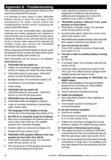
38 TRACKER 5100/5100i/5500/5500i Installation and Operation ManualNAVMAN
Appendix B - TroubleshootingThis troubleshooting guide assumes that you haveread and understood this manual.
It is possible in many cases to solve difficultieswithout having to send the unit back to themanufacturer for repair. Please follow thistroubleshooting section before contacting thenearest NAVMAN dealer.
There are no user serviceable parts. Specialisedmethods and testing equipment are required toensure that the unit is reassembled correctly and iswaterproof. Repairs to the unit must only be carriedout by a service centre approved by Navman NZLimited. Users who service the TRACKERthemselves will void the warranty.
When contacting a NAVMAN dealer for service, quotethe software version number and date which is givenon the about display (see section 12).
More information can be found on our Website:www.navman.com
1 TRACKER will not switch on:a Cables not connected or plugged into wrong
sockets in display unit. Match the plug colours.
b TRACKER wired for auto power. TRACKERwill turn on and off with boat power.
c Backlight too low. Turn on full (see section 2-3).
d Fuse blown or circuit breaker tripped.
e Faulty wiring.
2 TRACKER will not switch off:TRACKER wired for auto power. TRACKERwill turn on and off with boat power.
3 TRACKER turns off unexpectedly:a Power/data cable not plugged in properly.
b Loose or corroded connection in power/datacable. Check cable.
4 The language on the display is wrong:Choose the correct language (see section 13-1).
5 No GPS fix or long time to get fix at startup:a May occur occasionally if the antenna does not
have a clear view of the sky. The satellitepositions are constantly changing.
b Antenna cable not connected to display unit.
c Restart GPS (see section 13-3).
6 TRACKER GPS position different from trueposition by more than 10 m (33 ft):
a TRACKER in simulate mode. Turn simulatemode off (see section 13-10).
b The normal error in GPS position will exceed10 m (33 ft) for about 5% of the time.
c Under special circumstances the USDepartment of Defence may introduce adeliberate and changing error in the GPSpositions of up to 300 m (1000 ft).
7 TRACKER position different from sameposition on local charts:
a TRACKER in simulate mode. Turn simulatemode off (see section 13-10).
b Incorrect chart datum. Select the correct chartdatum (see section 13-2).
c Map shift has been applied wrongly. Clear map shift,then reapply if necessary (see section 13-2).
8 Can not see boat on chart:Press ESC to switch to centre on boat mode(see section 3-1-1).
9 The time or date on satellite display is wrongor off:
a No GPS fix.
b In simulate mode. Turn simulate mode off (seesection 13-10).
c Local time offset is wrong (see section 13-9).The Local Time Offset must be changed whendaylight saving time starts or ends.
10 Autopilot not responding to TRACKER; noNMEA output:
a NMEA output disabled or the required NMEAsentences are not turned on. Check NMEAsettings (see section 13-8).
b Check instrument connected correctly.
11 Depth not displayed:a Set a data field to Depth in chart, highway or
data displays.
b Check depth sounder is working andconnected properly.
12 No fuel functions available:a Fuel kit not installed.
b Fuel functions not enabled. Set Num Enginesto 1 or 2 (see section 13-4).
c Cables not connected or plugged into wrongsockets in display unit. Match the plug colours.
13 Fuel Used or Remaining seem wrong:a The engine has been run while the TRACKER
is turned off and it has not recorded the fuel use.Wire the auto power option (see section 15-3).
b Fuel may be surging back and forward througha transducer in rough seas. Try installing a oneway valve between the fuel transducer and thefuel tank.

39TRACKER 5100/5100i/5500/5500i Installation and Operation ManualNAVMAN
c Tank Full or Set Remaining has not been setevery refuelling.
d When refuelling, air pockets may haveprevented the tank filling completely.
e Fuel transducers wear out over time andshould be replaced every 5000 litres(1316 US gallons) of fuel as a guide.
14 No or low fuel flow reading:a Check the fuel cable connectors are securely
plugged in and the locking ring is locked inplace.
b Clogged fuel transducer. To clean atransducer, remove it from the line and gentlyblow through it in the opposite direction to thefuel flow. Fit a fuel filter before the transducer.
c Inspect the fuel cable(s) for damage.
d Dirty fuel filter.
e Fuel transducer has been exposed toexcessive heat or vibration.
Appendix C - Glossary and navigation dataGlossaryAttention Area - An important area on a chart, suchas a restricted anchorage or a shallow area (seesection 13-2).
Bathymetric line - A depth contour line on the chart.
Chart card - A plug-in card that stores chart data fora region (see section 1-2).
C-MAP™ chart card - See Chart card.
C-MAP™ user card - See User card.
Cursor - A symbol on the display (see section 3-1-1).
DGPS - Differential Global Positioning System. Anavigation tool based on GPS with some errorscorrected (see section 7).
Goto - A simple way of navigating straight to awaypoint or to the cursor position (see section 3-3).
GPS - Global Positioning System. A satellite-basednavigation tool (see section 7).
Leg - The straight segments of a route betweenwaypoints. A route with four waypoints has three legs.
MOB - Man overboard.
MOB function - Starts navigating back to the placewhere someone fell overboard (see section 2-4).
NavBus - A way of connecting NAVMAN instrumentstogether to share data (see section 14).
NMEA - National Marine Electronics Association.
NMEA 0183 - A standard for interfacing marineelectronic devices (see section 14).
Route: Two or more waypoints linked in sequenceto form a course for the boat (see section 10).
User card - A plug-in card that stores waypoints,routes and tracks (see section 1-2).
UTC - Universal Time Coordinated or CoordinatedUniversal Time, which is a standard world time,formerly called Greenwich Mean Time (GMT).
Waypoint - A user-definable chart position (seesection 9).
15 Only one flow rate value shown for a twinengine installation:
Set Num Engines to 2 (see section 13-4).
16 Erratic fuel flow readings:a The fuel transducer must not be mounted too
close to the fuel pump(s) and not subject toexcess vibration.
b Check for air leaks in the fuel hose(s) or fuelpick-up(s) in the tank(s).
c The Flow Filter has not been set to suit theengine(s) (see section 13-4). Increase theFlow Filter value until a steady flow rate isindicated.
17 TRACKER operates erratically orunexpectedly:Setup data incorrect. Reset to factory defaults(see section 13-1).

40 TRACKER 5100/5100i/5500/5500i Installation and Operation ManualNAVMAN
Navigation dataThe boat is sailing from the start to the destination and has moved off the plotted course from the start to thedestination.
BRG Bearing to Destination Bearing to the destination from the boat.
+BRG Bearing to cursor Bearing to cursor from boat (cursor mode, see section 3-1-1).
CDI Course Deviation Indicator When the boat is navigating to a point, the chart and highway displaysshow a parallel line on either side of the plotted course. These twolines are called the Course Deviation Indicator (CDI) lines. The distancefrom the plotted course to a CDI line is the CDI scale.
Set the CDI scale (see section 13-2) to the maximum distance that theboat should deviate from the plotted course. The chart and highwaydisplays show the CDI lines, which are like a highway over the waterwhere the boat will move. The displays show how far the boat hasdeviated from the plotted course and if the boat is approaching a CDIline. If the XTE alarm is enabled (see section 13-6) an alarm will soundif the boat reaches a CDI line.
COG Course Over Ground Direction in which the boat is moving over the ground.
CTS Course To Steer Optimum course to steer to return to the plotted course.
DTG Distance To Go Distance from the boat to the destination.
ETA Expected Time of Arrival At the destination, assuming that SOG and COG remain constant.
+RNG Range to cursor Distance from boat to cursor (cursor mode, see section 3-1-1).
SOG Speed Over Ground Current boat speed over the ground. This is not necessarily the sameas the boat speed through the water nor the speed at which it isapproaching the destination.
STR Steering The difference between COG and CTS.
TTG Time To Go The estimated time to reach the destination.
XTE Cross Track Error The distance from the boat to the nearest point of the plotted course.XTE may have a letter: R means steer to the right to return to the plottedcourse, L means steer to the left.
VMG Velocity Made Good The speed at which the boat is approaching the destination.
CTS
SOG (speed) VMG (speed)
BRGCOG
Destination
Boat positionStart
STR
DTG (distance)
CDI scale(distance)
Plottedcourse
Start
Destination
XTE(distance)
Boatposition
CDI scale(distance)
CD
I lin
e
Plottedcourse
CD
I lin
e

119TRACKER 5100/5100i/5500/5500i Manual de Instalação e FuncionamentoNAVMAN
NORTH AMERICA
NAVMAN USA INC.
18 Pine St. Ext.
Nashua, NH 03060.
Ph: +1 603 577 9600
Fax: +1 603 577 4577
e-mail: [email protected]
OCEANIA
New Zealand
Absolute Marine Ltd.
Unit B, 138 Harris Road,
East Tamaki, Auckland.
Ph: +64 9 273 9273
Fax: +64 9 273 9099
e-mail:
Australia
NAVMAN AUSTRALIA PTY
Limited
Unit 6 / 5-13 Parsons St,
Rozelle, NSW 2039, Australia.
Ph: +61 2 9818 8382
Fax: +61 2 9818 8386
e-mail: [email protected]
SOUTH AMERICA
Argentina
HERBY Marina S.A.
Costanera UNO,
Av Pte Castillo Calle 13
1425 Buenos Aires, Argentina.
Ph: +54 11 4312 4545
Fax: +54 11 4312 5258
e-mail:
Brazil
REALMARINE
Estrada do Joa 3862,
CEP2611-020,
Barra da Tijuca, Rio de Janeiro,
Brasil.
Ph: +55 21 2483 9700
Fax: +55 21 2495 6823
e-mail:
Equinautic Com Imp Exp de
Equip Nauticos Ltda.
Av. Diario de Noticias 1997 CEP
90810-080, Bairro Cristal, Porto
Alegre - RS, Brasil.
Ph: +55 51 3242 9972
Fax: +55 51 3241 1134
e-mail:
ASIA
China
Peaceful Marine Electronics Co. Ltd.
Hong Kong, Guangzhou,
Shanghai, Qindao, Dalian.
E210, Huang Hua Gang Ke Mao
Street, 81 Xian Lie Zhong Road,
510070 Guangzhou, China.
Ph: +86 20 3869 8784
Fax: +86 20 3869 8780
e-mail:
Website:
www.peaceful-marine.com
Korea
Kumho Marine Technology Co. Ltd.
# 604-816, 3F, 1117-34,
Koejung4-Dong, Saha-ku
Pusan, Korea
Ph: +82 51 293 8589
Fax: +82 51 294 0341
e-mail: [email protected]
Website:
www.kumhomarine.com
Malaysia
Advanced Equipment Co.
43A, Jalan Jejaka 2, Taman
Maluri, Cheras 55100, Kuala Lumpur.
Ph: +60 3 9285 8062
Fax: +60 3 9285 0162
e-mail: [email protected]
Singapore
RIQ PTE Ltd.
Blk 3007, Ubi Road 1,
#02-440, Singapore 408701
Ph: +65 6741 3723
Fax: +65 6741 3746
HP: +65 9679 5903
e-mail: [email protected]
Thailand
Thong Electronics (Thailand)
Company Ltd.
923/588 Sethakit 1 Road,
Mahachai,
Muang, Samutsakhon 74000,
Thailand.
Ph: +66 34 411 919
Fax: +66 34 422 919
e-mail: [email protected]
Vietnam
Haidang Co. Ltd.
16A/A1E, Ba thang hai St.
District 10, Hochiminh City.
Ph: +84 8 86321 59
Fax: +84 8 86321 59
e-mail:
Website: www.haidangvn.com
MIDDLE EAST
Lebanon and Syria
Letro, Balco Stores,
Moutran Street, Tripoli
VIA Beirut.
Ph: +961 6 624512
Fax: +961 6 628211
e-mail: [email protected]
United Arab Emirates
Kuwait, Oman & Saudi Arabia
AMIT, opp Creak Rd.
Baniyas Road, Dubai.
Ph: +971 4 229 1195
Fax: +971 4 229 1198
e-mail: [email protected]
AFRICA
South Africa
Pertec (Pty) Ltd Coastal,
Division No.16 Paarden Eiland Rd.
Paarden Eiland, 7405
Postal Address: PO Box 527,
Paarden Eiland 7420
Cape Town, South Africa.
Ph: +27 21 511 5055
Fax: +27 21 511 5022
e-mail: [email protected]
EUROPE
France, Belgium and
Switzerland
PLASTIMO INTERNATIONAL
15, rue Ingénieur Verrière,
BP435,
56325 Lorient Cedex.
Ph: +33 2 97 87 36 36
Fax: +33 2 97 87 36 49
e-mail: [email protected]
Website: www.plastimo.fr
Germany
PLASTIMO DEUTSCHLAND
15, rue Ingénieur Verrière
BP435
56325 Lorient Cedex.
Ph: +49 6105 92 10 09
+49 6105 92 10 10
+49 6105 92 10 12
Fax: +49 6105 92 10 11
e-mail:
Website: www.plastimo.de
Italy
PLASTIMO ITALIA
Nuova Rade spa, Via del Pontasso 5
I-16015 CASELLA SCRIVIA (GE).
Ph: +39 1096 8011
Fax: +39 1096 8015
e-mail: [email protected]
Website: www.plastimo.it
Holland
PLASTIMO HOLLAND BV.
Industrieweg 4,
2871 JE SCHOONHOVEN.
Ph: +31 182 320 522
Fax: +31 182 320 519
e-mail: [email protected]
Website: www.plastimo.nl
United Kingdom
PLASTIMO Mfg. UK Ltd.
School Lane - Chandlers Ford
Industrial Estate,
EASTLEIGH - HANTS S053 ADG.
Ph: +44 23 8026 3311
Fax: +44 23 8026 6328
e-mail: [email protected]
Website: www.plastimo.co.uk
Sweden, Denmark or Finland
PLASTIMO NORDIC AB.
Box 28 - Lundenvägen 2,
47321 HENAN.
Ph: +46 304 360 60
Fax: +46 304 307 43
e-mail: [email protected]
Website: www.plastimo.se
Spain
PLASTIMO ESPAÑA, S.A.
Avenida Narcís Monturiol, 17
08339 VILASSAR DE DALT,
(Barcelona).
Ph: +34 93 750 75 04
Fax: +34 93 750 75 34
e-mail: [email protected]
Website: www.plastimo.es
Other countries in Europe
PLASTIMO INTERNATIONAL
15, rue Ingénieur Verrière
BP435
56325 Lorient Cedex, France.
Ph: +33 2 97 87 36 59
Fax: +33 2 97 87 36 29
e-mail:
Website: www.plastimo.com
REST OF WORLD /
MANUFACTURERS
NAVMAN NZ Limited
13-17 Kawana St. Northcote.
P.O. Box 68 155 Newton,
Auckland, New Zealand.
Ph: +64 9 481 0500
Fax: +64 9 480 3176
e-mail:
Website:
www.navman.com
Appendix D - How to contact us www.navman.com.

80 NAVMAN MULTI 3100 Installation and Operation Manual
Lon
174°
44.
535`
E
Lat 36° 48.404`S
Made in New ZealandMN000089B
NAVMAN
TR
AC
KE
R 5
100/
5100
i550
0/55
00i