modelling of masonry infill walls participation in the ... · pdf filemodelling of masonry...
TRANSCRIPT

ORIGINAL RESEARCH
Modelling of masonry infill walls participation in the seismicbehaviour of RC buildings using OpenSees
Andre Furtado1 • Hugo Rodrigues2 • Antonio Arede1
Received: 18 July 2014 / Accepted: 30 March 2015 / Published online: 15 April 2015
� The Author(s) 2015. This article is published with open access at Springerlink.com
Abstract Recent earthquakes show that masonry infill
walls should be taken into account during the design and
assessment process of structures, since this type of non-
structural elements increase the in-plane stiffness of the
structure and consequently the natural period. An overview
of the past researches conducted on the modelling of ma-
sonry infilled frame issues has been done, with discussion
of past analytical investigations and different modelling
approaches that many authors have proposed, including
micro- and macro-modelling strategies. After this, the
present work presents an improved numerical model, based
on the Rodrigues et al. (J Earthq Eng 14:390–416, 2010)
approach, for simulating the masonry infill walls behaviour
in the computer program OpenSees. The main results of the
in-plane calibration analyses obtained with one ex-
perimental test are presented and discussed. For last, two
reinforced concrete regular buildings were studied and
subjected to several ground motions, with and without in-
fills’ walls.
Keywords Masonry infill walls � In-plane behaviour �Regular RC buildings � Vulnerability
Introduction
The presence of masonry infill walls in reinforced concrete
(RC) buildings is very common; however, and even today,
during the design process of new buildings and in the
assessment of existing ones, infills are usually considered
to be non-structural elements, and their influence on the
structural response is ignored. Their influence is recognized
in the global behaviour of RC frames subjected to earth-
quake loadings (Asteris and Cotsovos 2012; Crisafulli
1997b; Davis et al. 2004; Kakaletsis and Karayannis 2008;
Manfredi et al. 2012; Mosalam et al. 1997).
Over the last years, many authors have studied the ef-
fects of the infill panels on the response of RC structures
and the need of inclusion of these non-structural elements
on the structural seismic assessment and design process is
recognized. Observations made by technicians and experts
to damaged buildings caused by seismic actions (Fig. 1a)
proved that the presence of masonry infill walls can have
beneficial or negative effects to the structure. The negative
effects are associated with plan or vertical irregularities
introduced by the infill panels (Varum 2003a), potentially
causing different types of mechanisms such as the soft-
storey mechanism (Fig. 1b) (Furtado et al. 2014) or short-
column mechanism (Dolsek and Fajfar 2001; Furtado
2013). The presence of the infills is commonly associated
with the significant increase in the overall structural stiff-
ness implied by the infills, and then, a higher natural fre-
quency of vibration, which depends on the relevant seismic
spectrum, can lead to an increase in seismic forces.
The large in-plane shear demands that masonry infill
walls are subjected to are likely to increase their out-of-
plane vulnerability. The associated collapse can result in
serious human and material consequences as observed in
recent earthquakes (Fig. 1c). The full knowledge of all the
& Hugo Rodrigues
1 Faculdade de Engenharia da Universidade do Porto, Porto,
Portugal
2 ESTG, Instituto Politecnico de Leiria, Leiria, Portugal
123
Int J Adv Struct Eng (2015) 7:117–127
DOI 10.1007/s40091-015-0086-5

components (structural and non-structural elements) is
fundamental to help and guide the designers during the
assessment and strengthening process of existing buildings
with the main goal of reducing their seismic vulnerability.
The main objective of this work is to present a nu-
merical tool to represent the masonry infills’ in-plane be-
haviour in the computer program OpenSees (Mckenna
et al. 2000), based on the model developed by Rodrigues
et al. (2010). The in-plane calibration was performed based
on the experimental test performed by Pires (1990) in
LNEC (Civil Engineering National Laboratory, in Por-
tuguese). After this, two RC buildings with infill panels
with equal bay-size dimension but different number of
storeys and different disposition of the infill panels were
studied, in order to evaluate the effect of the infills’ pres-
ence in their structural response when subjected to seismic
actions.
Background on masonry infill wall modellingapproaches
In the literature, different modelling proposal techniques
that simulate the behaviour of the infills’ panels can be
found and are divided in two different groups, namely
micro-models and simplified macro-models. The first of
them involves models in which the panel is divided into
numerous elements taking into account the local effects in
detail, and the second includes simplified models based on
the physical understanding of the behaviour of the infills’
panels submitted to earthquakes loadings and past ex-
perimental tests. In the case of the last group, a few number
of struts are used to represent the effect of this non-struc-
tural element on the structural response.
Micro-modelling
The micro-modelling approach considers the effect of the
mortar joints as discrete element in the model. Considering
the fact of mortar joints are the weakest plane in a masonry
infill wall, this approach can be considered the most exact.
According to Lourenco (2002) and Asteris and Tzamtzis
(2003), the micro-modelling procedures can be summa-
rized in two different refinements for masonry walls:
simplified micro-modelling where the expanded units are
represent by continuum elements and the properties of the
mortar and the brick–mortar interface are lumped into a
common element (Fig. 2a) and detailed micro-modelling
(Fig. 2b) where brick units and the mortar are represented
by continuum elements and the brick units–mortar inter-
action are represent by different continuum elements,
which leads to accurate results and intensive computational
requirement (Asteris et al. 2013).
Mallick and Severn (1968) started in 1967 to apply the
finite-element method for modelling infilled frame struc-
tures. Depending on the composite characteristics of the
infilled frames, different elements are required in the model
as for example beam or continuum elements for the sur-
rounding frame, continuous elements for the infill panels
and interface elements for representing the interaction be-
tween the frame and the panel. The main advantage of the
micro-modelling is that the infilled frames’ in-plane be-
haviour takes into account with the local effects related to
cracking, crushing and contact interaction.
Dhanasekar and Page (1986) proposed 1D joint element
to model the separation and shear failure of the joint, and
the wall was modelled homogenously. They used the re-
sults of 186 half-scale square panels to define the infill
Fig. 1 a Infill walls collapse (Romao et al. 2013), b soft-storey mechanism (Costa et al. 2010) and c out-of-plane and in-plane damage
mechanisms in exterior masonry walls (Romao et al. 2013)
(a) (b)
mortarBrickunit
Brickelement
Mortarelement
Interfaceelement
Fig. 2 a Masonry infill wall sample, b detailed micro-modelling
strategy
118 Int J Adv Struct Eng (2015) 7:117–127
123
panel nonlinear material properties. Lofti and Shing studied
in 1991 the efficiency of homogenous smeared-crack
models to capture the response of reinforced masonry wall,
and they showed that the smeared-crack model can accu-
rately capture the flexural failure of the reinforced masonry
wall (Lofti and Shing 1991). Mehrabi and Shing (1997)
proposed a simplified micro-modelling model that
simulated the cracking, crushing and sliding of masonry
panel for cyclic and monotonic response. Lourenco and
Rots (1997) developed in 1997 an elasto-plastic constitu-
tive model for interface element which shows the ability to
capture the peak load and post-peak behaviour of the infill
panel when compared to experimental results.
Oliveira and Lourenco (2004) developed a constitutive
model based on the earlier interface element to simulate the
cyclic behaviour of the interface element recurring to
8-node continuum plane stress element to model the ma-
sonry units. Most recently, Stavridis and Shing (2010) and
Koutromanos et al. (2011) proposed different micro-mod-
elling approaches, and another couple of micro-modelling
approaches can be found at Asteris et al. (2013).
Macro-modelling
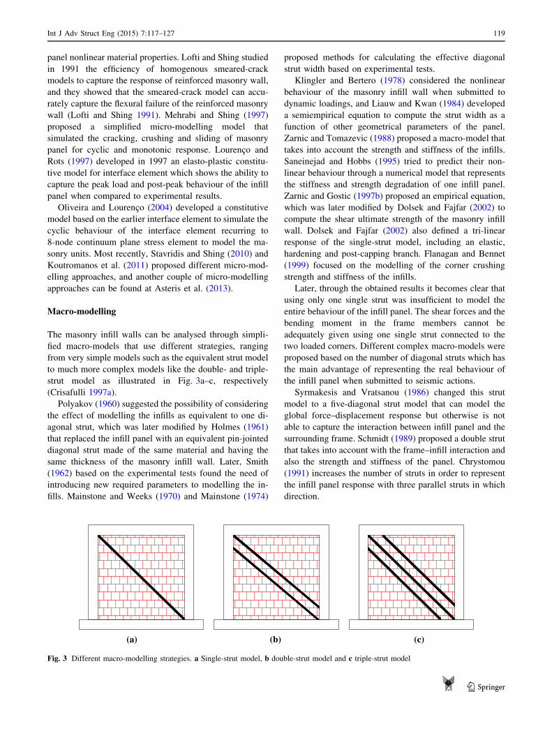
The masonry infill walls can be analysed through simpli-
fied macro-models that use different strategies, ranging
from very simple models such as the equivalent strut model
to much more complex models like the double- and triple-
strut model as illustrated in Fig. 3a–c, respectively
(Crisafulli 1997a).
Polyakov (1960) suggested the possibility of considering
the effect of modelling the infills as equivalent to one di-
agonal strut, which was later modified by Holmes (1961)
that replaced the infill panel with an equivalent pin-jointed
diagonal strut made of the same material and having the
same thickness of the masonry infill wall. Later, Smith
(1962) based on the experimental tests found the need of
introducing new required parameters to modelling the in-
fills. Mainstone and Weeks (1970) and Mainstone (1974)
proposed methods for calculating the effective diagonal
strut width based on experimental tests.
Klingler and Bertero (1978) considered the nonlinear
behaviour of the masonry infill wall when submitted to
dynamic loadings, and Liauw and Kwan (1984) developed
a semiempirical equation to compute the strut width as a
function of other geometrical parameters of the panel.
Zarnic and Tomazevic (1988) proposed a macro-model that
takes into account the strength and stiffness of the infills.
Saneinejad and Hobbs (1995) tried to predict their non-
linear behaviour through a numerical model that represents
the stiffness and strength degradation of one infill panel.
Zarnic and Gostic (1997b) proposed an empirical equation,
which was later modified by Dolsek and Fajfar (2002) to
compute the shear ultimate strength of the masonry infill
wall. Dolsek and Fajfar (2002) also defined a tri-linear
response of the single-strut model, including an elastic,
hardening and post-capping branch. Flanagan and Bennet
(1999) focused on the modelling of the corner crushing
strength and stiffness of the infills.
Later, through the obtained results it becomes clear that
using only one single strut was insufficient to model the
entire behaviour of the infill panel. The shear forces and the
bending moment in the frame members cannot be
adequately given using one single strut connected to the
two loaded corners. Different complex macro-models were
proposed based on the number of diagonal struts which has
the main advantage of representing the real behaviour of
the infill panel when submitted to seismic actions.
Syrmakesis and Vratsanou (1986) changed this strut
model to a five-diagonal strut model that can model the
global force–displacement response but otherwise is not
able to capture the interaction between infill panel and the
surrounding frame. Schmidt (1989) proposed a double strut
that takes into account with the frame–infill interaction and
also the strength and stiffness of the panel. Chrystomou
(1991) increases the number of struts in order to represent
the infill panel response with three parallel struts in which
direction.
(a) (b) (c)
Fig. 3 Different macro-modelling strategies. a Single-strut model, b double-strut model and c triple-strut model
Int J Adv Struct Eng (2015) 7:117–127 119
123

Crisafully (1997a) investigated the influence of different
multi-strut models on the structural response of masonry
infill walls, focusing in particular on the interaction with
surrounding frames and the stiffness of the structure.
Crisafulli (Smyrou et al. 2011) adopted a double-strut
model approach that is accurate enough and less compli-
cated than other models.
El-Dakhakhni et al. (2003) developed a model with
three non-parallel struts to reproduce the proper moment
diagram of the columns in an infilled due to the interaction
between infill and the surrounding frame and also to
adequately capture the corner crushing failure mechanism.
Crisafulli and Carr (2007) proposed a new macro-model
as a four-node panel, which is connected to the frame at the
beam–column joints and is composed of two parallel struts
and a shear spring in each direction, takes into account the
compressive and shear behaviour of the infill panel.
Recently, Rodrigues et al. (Rodrigues 2005) proposed a
simplified macro-model which is an upgrading of the
equivalent bi-diagonal compression strut model (as shown
in Fig. 4), commonly used to simulate the nonlinear be-
haviour of infill masonry panels subjected to cyclic loads
and validate with experimental results obtained. Each
masonry panel is structurally defined by four support strut
elements with rigid behaviour and one central strut ele-
ment, where the nonlinear hysteretic behaviour is concen-
trated (Fig. 4). This particular macro-model considers how
the in-plane damage in one direction affects the infills’
behaviour in the other direction. Therefore, the proposed
model represents more accurately the global response and
energy dissipation during structural response.
Proposed procedure for masonry infill wallmodelling in OpenSees
The macro-model proposed here to be used in the computer
program OpenSees (Mckenna et al. 2000) is based on the
Rodrigues et al. (2010) proposal model which is an im-
provement of the commonly used equivalent bi-diagonal
strut model, as said before. This simplified macro-model
does not take into account the short-column effects. For
infilled frames where the short-column effect can be in-
duced, multiple-strut model strategy should be adopted.
In this model (Rodrigues et al. 2010), each infill panel is
defined by considering four support strut elements, with
rigid in-plane behaviour, and a central element, where the
in-plane nonlinear hysteretic behaviour is concentrated, as
illustrated in Fig. 5a, b. The forces developed in the central
element are purely of tensile or compressive nature when
submitted to in-plane solicitations. The idealization of the
central element nonlinear monotonic behaviour was char-
acterized by a multi-linear curve, defined by eight pa-
rameters (Fig. 5c), representing: (a) cracking (cracking
force Fc and cracking dc); (b) yielding (yielding force Fy
and yielding displacement dy); (c) maximum strength,
corresponding to the beginning of crushing (Fmax and
corresponding displacement dmax); (d) residual strength
(Fu) and corresponding displacement (du). The hysteretic
rules calibrated for infills’ models are controlled by three
additional parameters such: stiffness degradation—a,pinching effect—b and strength degradation—c.
The proposed macro-model for masonry infill walls was
implemented in OpenSees (Mckenna et al. 2000) with the
association of the available OpenSees materials, sections
and elements commands. The infill model is composed of
four elastic beam columns for the diagonal elements and
one nonlinear beam column for the central element. The
Pinching 4 uniaxial material model (Fig. 6) was used toFig. 4 Rodrigues et al.’s simplified macro-model (Rodrigues 2005)
(a) (b) (c)
Diagonal strut
non-linearelement Fc
FyFmax
Fu
dudFmaxdydc Inter-Storey drift (%)
Force (kN)
Fig. 5 a Macro-model, b hysteretic material behaviour for the simulation of a masonry infill panel (adapted by Rodrigues et al. 2010)
120 Int J Adv Struct Eng (2015) 7:117–127
123
represent the hysteretic rule and was calibrated with ex-
perimental characteristics of the infills.
This uniaxial material is adopted to represents a ‘‘pin-
ched’’ load-deformation response which exhibits degrada-
tion under cyclic loading. The strength and stiffness cyclic
degradation occur in three ways: unloading stiffness
degradation, reloading stiffness degradation and strength
degradation.
The parameters required to define this uniaxial material
hysteric behaviour can be obtained following different
authors and international codes recommendations. Previous
tests performed by different authors showed that the first
crack appears to drift values between 0.05 and 0.15 % of
drift (dc), and the respective cracking force (Fc) can be
determined through the relationship between dc and Em,
which is the elasticity modulus of the infill panel.
Manzouri (1995) and Shing et al. (2009) found that the
maximum strength (Fcr) occurs at approximately 0.25 % of
drift (dcr). The maximum strength can be calculated
through Eq. (1) proposed by Zarnic and Gornic (1997a) and
later modified by Dolsek and Fajfar (2008) where ftp is the
masonry crack stress obtained based on experimental tests;
the t, Lin and h0 are the thickness, length and height of the
panel, respectively.
Fmax ¼ 0:818Lin � t � ftp
CI
1þffiffiffiffiffiffiffiffiffiffiffiffiffiffi
C2I þ 1
q
� �
ð1Þ
CI ¼ 1:925Lin
h0ð2Þ
The ratio of cracking and maximum strength (Fy/Fcr) is
adopted as 0.55 following Dolsek and Fajfar (2008) rec-
ommendations and the experimental tests performed by
Manzouri (1995).
The post-peak strength degradation is based on Dolsek
and Fajfar (2008) that estimate the displacement at residual
strength (du) is five times of the displacement of maximum
stress. The value of the residual strength is about 20 % of
the maximum strength (Fu).
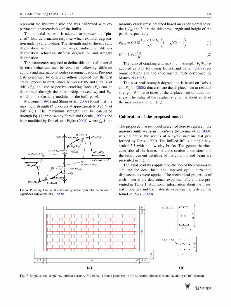
Calibration of the proposed model
The proposed macro-model presented here to represent the
masonry infill walls in OpenSees (Mckenna et al. 2000)
was calibrated the results of a cyclic in-plane test per-
formed by Pires (1990). The infilled RC is a single bay,
scaled 2:3 with hollow clay bricks. The geometric char-
acteristics of the frame, the cross section dimensions and
the reinforcement detailing of the columns and beam are
presented in Fig. 7.
The axial load was applied on the top of the columns to
simulate the dead load, and imposed cyclic horizontal
displacements were applied. The mechanical properties of
each material are determined experimentally and are pre-
sented in Table 1. Additional information about the mate-
rial properties and the materials experimental tests can be
found in Pires (1990)Fig. 6 Pinching 4 uniaxial material—generic hysteretic behaviour in
OpenSees (Mckenna et al. 2000)
(a) (b)
Fig. 7 Single-storey single-bay infilled masonry RC frame: a frame geometry. b Cross section dimensions and detailing of RC elements
Int J Adv Struct Eng (2015) 7:117–127 121
123
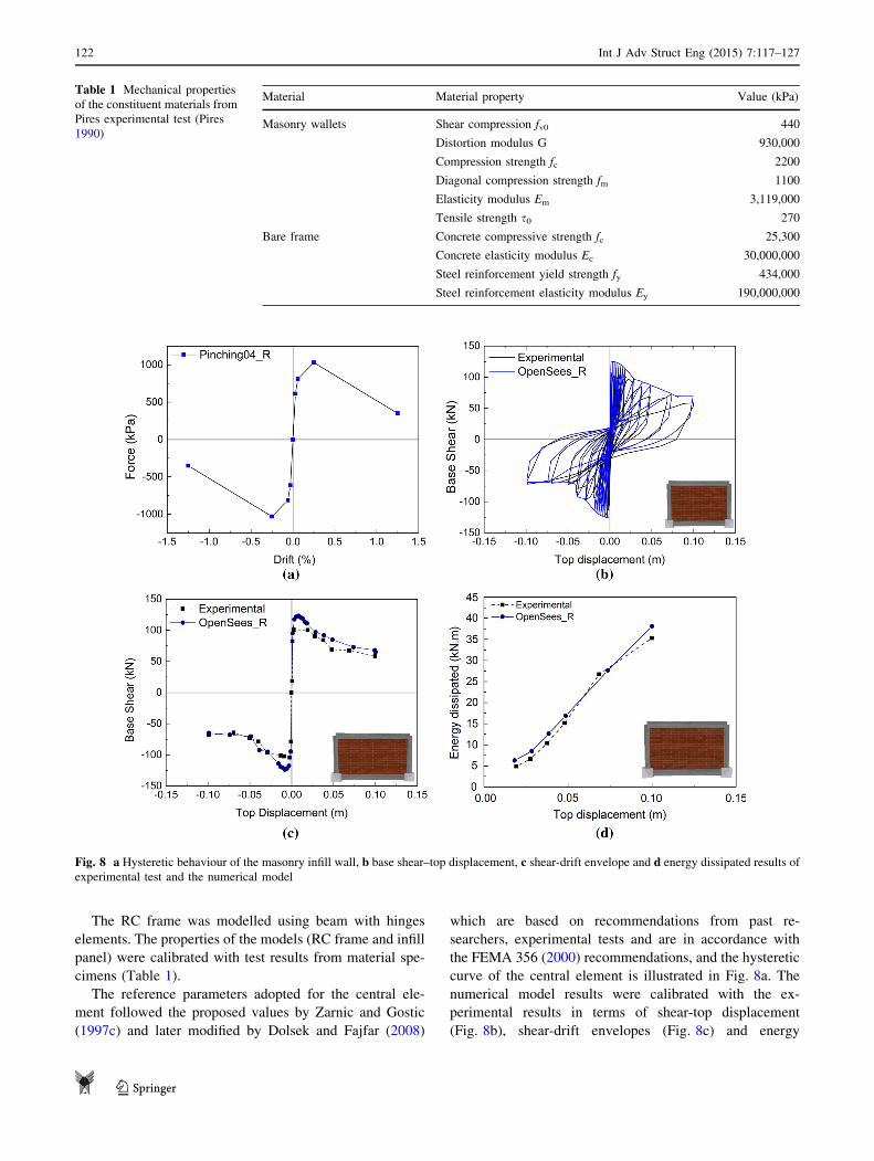
The RC frame was modelled using beam with hinges
elements. The properties of the models (RC frame and infill
panel) were calibrated with test results from material spe-
cimens (Table 1).
The reference parameters adopted for the central ele-
ment followed the proposed values by Zarnic and Gostic
(1997c) and later modified by Dolsek and Fajfar (2008)
which are based on recommendations from past re-
searchers, experimental tests and are in accordance with
the FEMA 356 (2000) recommendations, and the hysteretic
curve of the central element is illustrated in Fig. 8a. The
numerical model results were calibrated with the ex-
perimental results in terms of shear-top displacement
(Fig. 8b), shear-drift envelopes (Fig. 8c) and energy
Fig. 8 a Hysteretic behaviour of the masonry infill wall, b base shear–top displacement, c shear-drift envelope and d energy dissipated results of
experimental test and the numerical model
Table 1 Mechanical properties
of the constituent materials from
Pires experimental test (Pires
1990)
Material Material property Value (kPa)
Masonry wallets Shear compression fv0 440
Distortion modulus G 930,000
Compression strength fc 2200
Diagonal compression strength fm 1100
Elasticity modulus Em 3,119,000
Tensile strength s0 270
Bare frame Concrete compressive strength fc 25,300
Concrete elasticity modulus Ec 30,000,000
Steel reinforcement yield strength fy 434,000
Steel reinforcement elasticity modulus Ey 190,000,000
122 Int J Adv Struct Eng (2015) 7:117–127
123
dissipated (Fig. 8d). The obtained results with the nu-
merical model (OpenSees_R) are in good agreement with
the experimental response in terms of shear-top displace-
ment response (Fig. 8b, c) and energy dissipation (Fig. 8d)
demonstrating the ability of the proposed model to simulate
the global hysteretic response of infilled frames.
The base shear-top displacement envelope of the nu-
merical model is\5 % higher in terms of base shear for the
same top displacement values. The dissipated energy was
determined (Fig. 8d), and the numerical model shows a
good agreement with the experimental response, with
\5 % of difference which is acceptable because it is a
simplified model that is used to model the entire infill panel
and its surrounding frame elements. In general, the Open-
Sees_R results are in good agreement with experimental
results.
Case studies
With the aim of evaluating the influence of the masonry
infill walls in the structural response of existing buildings
when subjected to seismic loadings, two case studies will
be studied. The buildings were designed in a project carried
out by LNEC about structural design of structures sub-
mitted to seismic actions (Carvalho and Coelho 1984). The
columns are spaced by 4 m in longitudinal direction and
5 m in transversal direction with a storey height of 3 m and
illustrated in Fig. 9.
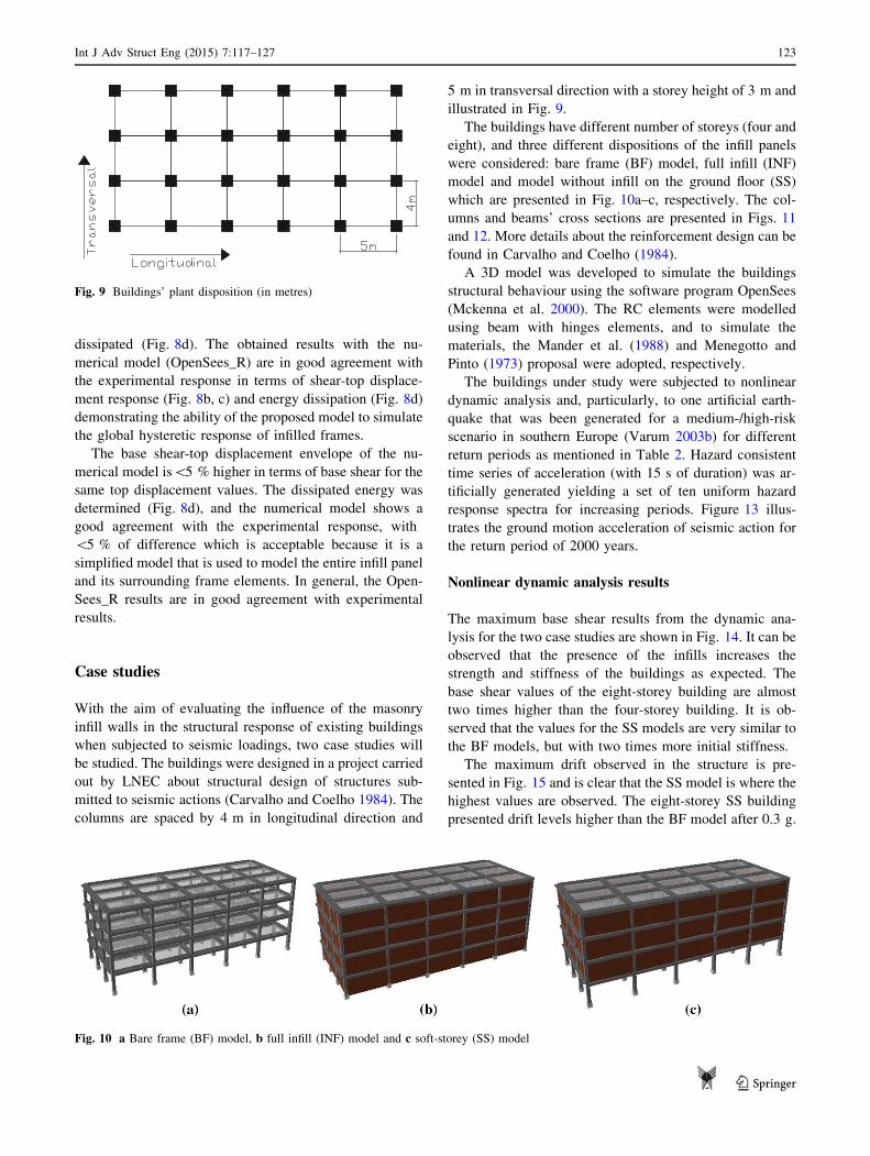
The buildings have different number of storeys (four and
eight), and three different dispositions of the infill panels
were considered: bare frame (BF) model, full infill (INF)
model and model without infill on the ground floor (SS)
which are presented in Fig. 10a–c, respectively. The col-
umns and beams’ cross sections are presented in Figs. 11
and 12. More details about the reinforcement design can be
found in Carvalho and Coelho (1984).
A 3D model was developed to simulate the buildings
structural behaviour using the software program OpenSees
(Mckenna et al. 2000). The RC elements were modelled
using beam with hinges elements, and to simulate the
materials, the Mander et al. (1988) and Menegotto and
Pinto (1973) proposal were adopted, respectively.
The buildings under study were subjected to nonlinear
dynamic analysis and, particularly, to one artificial earth-
quake that was been generated for a medium-/high-risk
scenario in southern Europe (Varum 2003b) for different
return periods as mentioned in Table 2. Hazard consistent
time series of acceleration (with 15 s of duration) was ar-
tificially generated yielding a set of ten uniform hazard
response spectra for increasing periods. Figure 13 illus-
trates the ground motion acceleration of seismic action for
the return period of 2000 years.
Nonlinear dynamic analysis results
The maximum base shear results from the dynamic ana-
lysis for the two case studies are shown in Fig. 14. It can be
observed that the presence of the infills increases the
strength and stiffness of the buildings as expected. The
base shear values of the eight-storey building are almost
two times higher than the four-storey building. It is ob-
served that the values for the SS models are very similar to
the BF models, but with two times more initial stiffness.
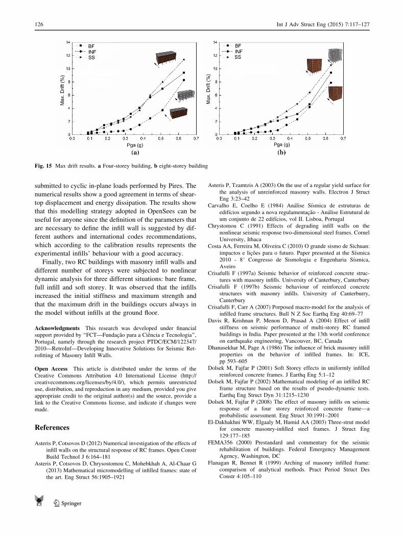
The maximum drift observed in the structure is pre-
sented in Fig. 15 and is clear that the SS model is where the
highest values are observed. The eight-storey SS building
presented drift levels higher than the BF model after 0.3 g.
Fig. 9 Buildings’ plant disposition (in metres)
Fig. 10 a Bare frame (BF) model, b full infill (INF) model and c soft-storey (SS) model
Int J Adv Struct Eng (2015) 7:117–127 123
123
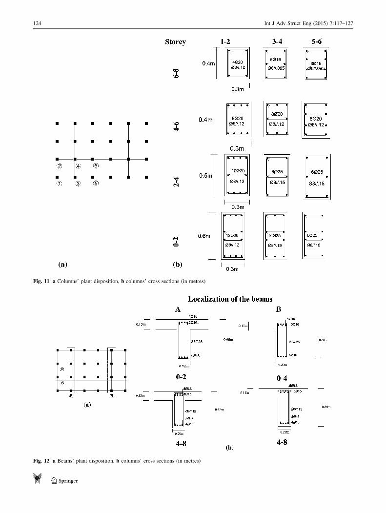
Fig. 11 a Columns’ plant disposition, b columns’ cross sections (in metres)
Fig. 12 a Beams’ plant disposition, b columns’ cross sections (in metres)
124 Int J Adv Struct Eng (2015) 7:117–127
123

This fact highlights the vulnerability of this type of
buildings, and the need to consider the infill walls par-
ticipation since a significant number of buildings do not
have masonry infill walls at the ground floor for architec-
tural options.
It is observed that for both of the buildings, the max-
imum drift of INF model has lower values until ap-
proximately 0.3 g and after that the values increase until
close to the BF model. For last, the maximum drift values
of the eight-storey building with four-storey building are
higher besides the BF model, where the values are lower
for the eight-storey building.
Conclusions
The masonry infill walls’ in-plane behaviour was investi-
gated in order to have a deep knowledge about the inter-
action with the surrounding frames and their nonlinear
behaviour during an earthquake. A brief state of art of
existing macro-modellings and micro-modellings was
performed. It was observed that the micro-models allow us
to obtain more accurate results, but otherwise they need
more computational requirements. The macro-models can
reproduce, with a good agreement, the real behaviour of
these non-structural elements with less computational re-
quirement and time. One of the difficulties of the macro-
models is the difficulty to represent infill panels with
openings.
This study presents a simplified macro-model that
simulates the nonlinear behaviour of the infill panels when
subjected to in-plane actions and the respective application
in the computer program OpenSees. This model, based on
the Rodrigues et al. proposal, is adopted from the typical
strut model considering the infill–surrounding frame in-
teraction in both directions and is composed by four di-
agonal struts and a nonlinear central element that represent
the nonlinear behaviour of the infills. A simplified proce-
dure to determine the required parameters to define the
model was presented followed by the validation of the
proposed method with available experimental data.
This proposed model was calibrated with the results of
one infilled single-storey experimental test that was
-4-3-2-10123
0 15
Acce
lera
�on
(m/s
2)
Fig. 13 Ground motion
acceleration time history for the
2000-year RP
Table 2 Peak ground acceleration and corresponding return period
(RP)
RP (years) Peak acceleration (m/s2)
73 0.889 (0.09 g)
100 1.060 (0.11 g)
170 1.402 (0.14 g)
300 1.796 (0.18 g)
475 2.180 (0.22 g)
700 2.543 (0.26 g)
975 2.884 (0.29 g)
1370 3.265 (0.33 g)
2000 3.728 (0.38 g)
3000 4.273 (0.44 g)
5000 5.036 (0.51 g)
9980 6.212 (0.63 g)
Fig. 14 Max base shear results. a Four-storey building, b eight-storey building
Int J Adv Struct Eng (2015) 7:117–127 125
123
submitted to cyclic in-plane loads performed by Pires. The
numerical results show a good agreement in terms of shear-
top displacement and energy dissipation. The results show
that this modelling strategy adopted in OpenSees can be
useful for anyone since the definition of the parameters that
are necessary to define the infill wall is suggested by dif-
ferent authors and international codes recommendations,
which according to the calibration results represents the
experimental infills’ behaviour with a good accuracy.
Finally, two RC buildings with masonry infill walls and
different number of storeys were subjected to nonlinear
dynamic analysis for three different situations: bare frame,
full infill and soft storey. It was observed that the infills
increased the initial stiffness and maximum strength and
that the maximum drift in the buildings occurs always in
the model without infills at the ground floor.
Acknowledgments This research was developed under financial
support provided by ‘‘FCT—Fundacao para a Ciencia e Tecnologia’’,
Portugal, namely through the research project PTDC/ECM/122347/
2010—RetroInf—Developing Innovative Solutions for Seismic Ret-
rofitting of Masonry Infill Walls.
Open Access This article is distributed under the terms of the
Creative Commons Attribution 4.0 International License (http://
creativecommons.org/licenses/by/4.0/), which permits unrestricted
use, distribution, and reproduction in any medium, provided you give
appropriate credit to the original author(s) and the source, provide a
link to the Creative Commons license, and indicate if changes were
made.
References
Asteris P, Cotsovos D (2012) Numerical investigation of the effects of
infill walls on the structural response of RC frames. Open Constr
Build Technol J 6:164–181
Asteris P, Cotsovos D, Chrysostomou C, Mohebkhah A, Al-Chaar G
(2013) Mathematical micromodelling of infilled frames: state of
the art. Eng Struct 56:1905–1921
Asteris P, Tzamtzis A (2003) On the use of a regular yield surface for
the analysis of unreinforced masonry walls. Electron J Struct
Eng 3:23–42
Carvalho E, Coelho E (1984) Analise Sısmica de estruturas de
edifıcios segundo a nova regulamentacao - Analise Estrutural de
um conjunto de 22 edifıcios, vol II. Lisboa, Portugal
Chrystomou C (1991) Effects of degrading infill walls on the
nonlinear seismic response two-dimensional steel frames. Cornel
University, Ithaca
Costa AA, Ferreira M, Oliveira C (2010) O grande sismo de Sichuan:
impactos e licoes para o futuro. Paper presented at the Sısmica
2010 - 88 Congresso de Sismologia e Engenharia Sısmica,
Aveiro
Crisafulli F (1997a) Seismic behavior of reinforced concrete struc-
tures with masonry infills. University of Canterbury, Canterbury
Crisafulli F (1997b) Seismic behaviour of reinforced concrete
structures with masonry infills. University of Canterburry,
Canterbury
Crisafulli F, Carr A (2007) Porposed macro-model for the analysis of
infilled frame structures. Bull N Z Soc Earthq Eng 40:69–77
Davis R, Krishnan P, Menon D, Prasad A (2004) Effect of infill
stiffness on seismic performance of multi-storey RC framed
buildings in India. Paper presented at the 13th world conference
on earthquake engineering, Vancouver, BC, Canada
Dhanasekhar M, Page A (1986) The influence of brick masonry infill
properties on the behavior of infilled frames. In: ICE,
pp 593–605
Dolsek M, Fajfar P (2001) Soft Storey effects in uniformly infilled
reinforced concrete frames. J Earthq Eng 5:1–12
Dolsek M, Fajfar P (2002) Mathematical modeling of an infilled RC
frame structure based on the results of pseudo-dynamic tests.
Earthq Eng Struct Dyn 31:1215–1230
Dolsek M, Fajfar P (2008) The effect of masonry infills on seismic
response of a four storey reinforced concrete frame—a
probabilistic assessment. Eng Struct 30:1991–2001
El-Dakhakhni WW, Elgaaly M, Hamid AA (2003) Three-strut model
for concrete masonry-infilled steel frames. J Struct Eng
129:177–185
FEMA356 (2000) Prestandard and commentary for the seismic
rehabilitation of buildings. Federal Emergency Management
Agency, Washington, DC
Flanagan R, Bennet R (1999) Arching of masonry infilled frame:
comparison of analytical methods. Pract Period Struct Des
Constr 4:105–110
Fig. 15 Max drift results. a Four-storey building, b eight-storey building
126 Int J Adv Struct Eng (2015) 7:117–127
123
Furtado A (2013) Avaliacao de solucoes de reforco para edificios com
r/c vazado. Universidade de Aveiro
Furtado A, Rodrigues H, Varum H, Costa A (2014) Assessment and
strengthening strategies of existing RC buildings with potential
soft-storey response. In: 9th international masonry conference
(IMC), Portugal
Holmes M (1961) Steel frames with brickwork and concrete filling.
Proc Inst Civ Eng 2 Res Theory 19:473–478
Kakaletsis D, Karayannis C (2008) Influence of masonry strenght and
openings on infilled R/C frames under cycling loading. J Earthq
Eng 12:197–221
Klingler R, Bertero V (1978) Earthquake resistance of infilled frames.
J Struct Div 104:973–989
Koutromanos I, Stravidris A, Shing P, Quenneville J (2011)
Numerical modelling of masonry-infilled RC frames subjected
to seismic loads. Comput Struct 89:1026–1037
Liauw T, Kwan K (1984) Nonlinear behavior of non-integral infilled
frames. Comput Struct 18:551–560
Lofti H, Shing P (1991) An appraisal of smeared crack models for
masonry shear wall analysis. Comput Struct 41:413–425
Lourenco P (2002) Computations on historic masonry structures. Prog
Struct Eng Mater 4:301–319
Lourenco P, Rots J (1997) Multisurface interface model for analysis
of masonry structures. J Eng Mech 123:660–668
Mainstone RJ (1974) Supplementary note on the stiffness and strength
of infilled frames. Building Research Station, UK, CP 13/74
Mainstone J, Weeks G (1970) The influence of bounding frame on the
racking stiffness and strength of brick walls. In: 2nd international
brick masonry conference, Watford
Mallick D, Seven R (1968) Dynamic characteristics of infilled frames.
ICE Proc 39(2):261–287
Mander J, Priestleyand M, Parks R (1988) Theoretical stress–strain
model for confined concrete. J Struct Eng 114:1804–1826
Manfredi G, Ricci P, Verderame G (2012) Influence of infill panels
and their distribution on seismic behavior of existing reinforced
concrete buildings. Open Constr Build Technol J 6:236–253
Manzouri T (1995) Nonlinear finite element analysis and experimen-
tal evaluation of retrofitting techniques for unreinforced masonry
structures. University of Colorado-Boulder, Boulder
Mckenna F, Fenves G, Scott M, Jeremic B (2000) Open system for
earthquake engineering simulation (OpenSees). Berkley, CA
Mehrabi A, Shing P (1997) Finite-element modelling of masonry-
infilled RC frames. J Struct Eng 123:604–613
Menegotto M, Pinto P (1973) Method of analysis for cyclically loaded
reinforced concrete plane frames including changes in geometry
and non-elastic behaviour of elements under combined normal
force and bending. Lisbon, Portugal
Mosalam K, Ayala G, White R, Roth C (1997) Seismic fragility of
LRC frames with and without masonry infill walls. J Earthq Eng
1:693–720
Oliveira D, Lourenco P (2004) Implementation and validation of a
constitutive model for the cyclic behaviour of interface elements.
Comput Struct 82:1451–1461
Pires F (1990) Influencia das paredes de alvenaria no comportamento
de estruturas de betao armado sujeitas a acoes horizontais. LNEC
Polyakov S (1960) On the interaction between masonry filler walls
and enclosing frame when loading in the plane of the wall.
Transl Earthq Eng E2:36–42
Rodrigues H (2005) Desenvolvimento e calibracao de modelos
numericos para a analise sısmica de edifıcios. Universidade do
Porto
Rodrigues H, Varum H, Costa A (2010) Simplified macro-model for
infill masonry panels. J Earthq Eng 14:390–416
Romao X, Costa AA, Pauperio E, Rodrigues H, Vicente R, Varum H,
Costa A (2013) Field observations and interpretation of the
structural performance of constructions after the 11 May 2011
Lorca earthquake. Eng Fail Anal 34:670–692
Saneinejad A, Hobbs B (1995) Inelastic design of infilled frames.
J Struct Eng 121:634–650
Schmidt T (1989) An approach of modelling masonry infilled frames
by the f.e. method and a modified equivalent strut model. Annu J
Concr Concr Struct 4:171–180
Shing P et al. (2009) Seismic performance of non-ductile RC frames
with brick infill. Paper presented at the improving the seismic
performance of existing buildings and other structures, ATC/S
EI
Smith S (1962) Lateral stiffness of infilled frames. J Struct Div
88:183–199
Smyrou E, Blandon C, Antoniou S, Pinho R, Crisafulli F (2011)
Implementation and verification of a masonry panel model for
nonlinear dynamic analysis of infilled RC frames. Bull Earthq
Eng 9:1519–1534
Stravidris A, Shing P (2010) Finite-element modelling of nonlinear
behavior of masonry infilled RC frames. J Struct Eng
136:285–296
Syrmakesis C, Vratsanou V (1986) Influence of infill walls to RC
frames response. In: 8th European conference on earthquake
engineering, Istanbul, Turkey, pp 47–53
Varum H (2003a) Seismic assessment, strengthening and repair of
existing buildings. Universidade de Aveiro
Varum H (2003b) Seismic assessment, strengthening and repair of
existing buildings. Universidade de Aveiro
Zarnic R, Gostic S (1997a) Masonry infilled frames as an effective
structural sub-assemblage. In: Fajfar P, Krawinkler H (eds)
Seismic design methodologies for the next generation of codes.
pp 335–346
Zarnic R, Gostic S (1997b) Masonry infilled frames as an effective
structural sub-assemblage. In: International workshop, Bled,
Slovenia
Zarnic R, Gostıc S (1997c) Masonry infilled frames as an effective
structural sub-assemblage. Paper presented at the seismic design
methodologies for the next generation of codes, Rotterdam,
Balkema
Zarnic R, Tomazevic M (1988) An experimentally obtained method
for evaluation of the behavior of masonry infilled RC frames. In:
9th world conference on earthquake engineering, pp 163–168
Int J Adv Struct Eng (2015) 7:117–127 127
123