motherboard user’s manual revision 1 1/tsunami … · displayed error messages ... •intel...
TRANSCRIPT

Tyan S1830
Tsunami AT
Motherboard User’s ManualRevision 1.30
Copyright © Tyan Computer Corporation, 1999. All rights reserved. No part of thismanual may be reproduced or translated without prior written consent from TyanComputer Corp.
All registered and unregistered trademarks and company names contained in thismanual are propery of their respective companies including, but not limited to thefollowing.AMIBIOS is a trademark of American Megatrends Incorporated.Windows is a trademark of Microsoft Corporation.IBM, PC, AT, PS/2 are trademarks of IBM Corporation.INTEL, Pentium II, Celeron are trademarks of Intel Corporation.S1830S/SL Tsunami AT is a trademark of TYAN Computer Corporation.
Information contained in this publication has been carefully checked for accuracy andreliability. In no event will Tyan Computer be held liable for any direct or indirect,incidental or consequential damage, loss of use, loss of data, or other malady resultingfrom errors or inaccuracies of information contained in this manual. The informationcontained in this document is subject to change without notice.
PRINTED IN USA
Table of Contents1. Introduction.................................................................................................... 4
Overview.............................................................................................. 4Icons.................................................................................................... 5Hardware Specifications/Features................................................... 5Software Specifications..................................................................... 7Technical Support.............................................................................. 8Returning Merchandise for Service................................................ 8
2. Board Installation......................................................................................... 10Unpacking........................................................................................... 10Installation.......................................................................................... 10Setting Jumpers.................................................................................. 23
3. Onboard Resource Settings........................................................................ 24Quick Reference for Jumpers............................................................ 24Map of Motherboard Jumpers......................................................... 25Hardware CMOS & Password Reset............................................... 28Soft Power Connector........................................................................ 29Speaker Connector Installation........................................................ 29Hardware Reset Switch Connector Installation............................. 29External SMI........................................................................................ 30CMOS RTC.......................................................................................... 30Flash EEPROM................................................................................... 30RAM Installation............................................................................... 31Cache Memory.................................................................................... 32Frequently Asked Questions........................................................... 32
4. BIOS Configuration..................................................................................... 34Main Setup......................................................................................... 35Advanced CMOS Setup................................................................... 40Chipset Setup..................................................................................... 45Power Management Setup................................................................ 51Plug and Play Setup........................................................................... 55Peripheral Setup................................................................................. 60
5. System Resources........................................................................................ 62Beep Codes......................................................................................... 62Troubleshooting System Problems................................................. 63Displayed Error Messages............................................................... 64Glossary............................................................................................... 66
http://www.tyan.com
4
Chapter 1Introduction
Overview
The S1830S and S1830SL (S1830) Tsunami AT is a quality, high performancemainboard designed for Intel Pentium II and Celeron microprocessors. Thismainboard utilizes the Intel 440BX AGPset and can support CPU speeds of233MHz through 450MHz, and host bus speeds of 66MHz or 100MHz. TheTsunami AT also has 100MHz Front Side Bus support, which allows you totake full advantage of 100MHz SDRAM memory modules.
The S1830 mainboard, with built-in AGP slot, provides high performancecapabilities that are ideal for a wide range of demanding applications such asCAD, CAM, CAE, desktop publishing, 3D animation, and video production.
This integrated system board achieves high reliability with numerous featuresand yet is small enough to be supported in a Baby AT form factor. Some of thefeatures included are onboard dual channel PCI PIO, Bus Master IDE andUltraDMA/33, onboard floppy controller, and onboard high speed I/O.
Flexibility and expandability have been designed into the Tsunami AT. With I/O and drive controller support built onboard, the one AGP slot, four PCI andfour ISA slots (one shared, eight usable) are free for numerous add-onepansion cards.
chap
ter 1
Introduction
S1830 Tsunami AT
5
INT
RO
Remember to take a look at TYAN Computer’s web site located athttp://www.tyan.com. There you can find information on all of TYAN’sproducts along with FAQs, distributors list, drivers, and BIOS setting explana-tions.
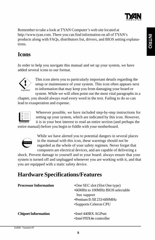
Icons
In order to help you navigate this manual and set up your system, we haveadded several icons to our format.
This icon alerts you to particularly important details regarding thesetup or maintenance of your system. This icon often appears nextto information that may keep you from damaging your board orsystem. While we will often point out the most vital paragraphs in a
chapter, you should always read every word in the text. Failing to do so canlead to exasperation and expense.
Wherever possible, we have included step-by-step instructions forsetting up your system, which are indicated by this icon. However,it is in your best interest to read an entire section (and perhaps the
entire manual) before you begin to fiddle with your motherboard.
While we have alerted you to potential dangers in several placesin the manual with this icon, these warnings should not beregarded as the whole of your safety regimen. Never forget thatcomputers are electrical devices, and are capable of delivering a
shock. Prevent damage to yourself and to your board: always ensure that yoursystem is turned off and unplugged whenever you are working with it, and thatyou are equipped with a static safety device.
Hardware Specifications/Features
Processor Information •One SEC slot (Slot One type)•66MHz to 100MHz BIOS selectable bus support•Pentium II /III 233-600MHz•Supports Celeron CPU
Chipset Information •Intel 440BX AGPset•Intel PIIX4e controller
!important!
procedure
1.2.3.
warning
http://www.tyan.com
6
Chapter 1Introduction
•National 309 Super I/O chipset
Voltage and Power •AT/ATX power supply connectorsInformation •+12V power source for DC fan
onboard•3.3V DRAM support•Utilizes GTL+ bus to reduce power consumption and EMI•Power recovery after interrupt•Wake-on LAN 3-pin header (requires ATX 2.01 compliant power supply)•VRM component installed onboard•Onboard CPU/chassis fan headers
Main Memory •Up to 1024MB onboard•Four 168-pin DIMM sockets•Supports 66 or 100MHz SDRAM (100 MHz SDRAM required for 100MHz bus speeds)•Supports SDRAM w/SPD, SDRAM+ECC
System Management •National LM79 and LM75(1830SL only) ASICs with onboard alarm for
monitoring temperature,supply voltages, and fan speed. Reports to the OS for system monitoring•Intel LANDesk® Client Manager software
Expansion Slots •One 32-bit AGP slot•Four 32-bit PCI Bus Master slots•Four 16-bit ISA slots•One shared, eight usable
Physical Dimensions •Baby AT design.•13 inches x 8.6 inches
BIOS Information •AMI Plug and Play flash BIOS•Deep Green, Energy Star, Year 2000
S1830 Tsunami AT
7
INT
RO
compliant•Yellow LED for sleep, PC98 ready
Disk Drive & System I/O •UltraDMA/33 (UIDE) built-in (up to 33MB/s DTR)•Two PCI bus mastering EIDE channels•Supports EIDE CD-ROMs•PIO Mode 3&4 (up to 17MB/s DTR)•Bus mastering mode (up to 22MB/s DTR)•Support for two floppy drives (supports Mode 3 and up to 2.88MB)•Two serial ports (16550 UARTs)•One ECP/EPP parallel port•One IR (InfraRed) I/O interface port header•Two USB rev 1.2 port headers.•One PS/2 mouse port.•One AT keyboard connector.
Warranty •3 year manufacturer’s warranty.
Software Specifications
OS •Operates with MS-DOS, Windows3.x, Windows for WorkGroups 3.x,Windows 95, Windows 98, WindowsNT, OS/2, Novell Netware, Solaris,and SCO Unix.
Information presented in this publication has been carefully checked forreliability. However, no responsibility is assumed for inaccuracies. Theinformation contained in this document is subject to change without notice.

http://www.tyan.com
8
Chapter 1Introduction
Technical Support
If a problem arises with your system, you should turn to your dealer for helpfirst. Your system has most likely been configured by them, and they shouldhave the best idea of what hardware and software your system contains.Hence, they should be of the most assistance. Further, if you purchased yoursystem from a dealer near to you, you can actually bring your system in tothem to have it serviced, instead of attempting to do so yourself (which canhave expensive consequences).
Help resources:1. See FAQ and beep codes sections of this manual.2. See Tyan web site for FAQ, bulletins, driver updates, etc.
http://www.tyan.com3. Contact your dealer or distributor for help BEFORE calling Tyan.4. Check the Tyan user group: alt.comp.periphs.mainboard.tyan5. Email Tyan tech support: [email protected]. Call Tyan tech support: 510-440-8808
Returning Merchandise for Service
During the warranty period, contact your distributor or system vendor FIRSTfor any product problems. This warranty only covers normal customer use anddoes not cover damages incurred during shipping or failure due to thealteration, misuse, abuse, or improper maintenance of products.
For Resellers Only:A receipt or copy of your invoice marked with the date of purchase is requiredbefore any warranty service can be rendered. You can obtain service by callingthe manufacturer for a Return Merchandise Authorization (RMA) number. TheRMA number should be prominently displayed on the outside of the shippingcarton and the package should be mailed prepaid, or hand-carried to themanufacturer. TYAN will pay to have the board shipped back to you.

S1830 Tsunami AT
9
This page has been intentionally left blank.
http://www.tyan.com
10
procedure
1.2.3.
Chapter 2Board Installation
chap
ter 2
Board Installation
Unpacking
The mainboard package should contain the following:(1) S1830S/SL mainboard(1) 40-pin IDE and 34-pin floppy cable pack(1) One PS/2 Mouse cable(1) User’s manual(1) CPU retention module(1) System Managment & Driver CD (Intel LANDesk - 1830SL only)(1) One BX Driver Diskette (1830S only)
Installation
You are now ready to install your mainboard. The mounting hole pattern of theS1830 matches the Baby AT system board specifications. Your chassis shouldbe that of a standard AT mainboard form factor with AT or ATX power supply.
How to install our products right...the first time.
What’s the first thing I should do?The first thing you should do is read this user’s manual. It contains important
S1830 Tsunami AT
11
information which will make configuration and setup much easier.
The next step is to properly ground yourself. First, unplug the power from yourcomputer case and then touch the metal casing of the power supply or anymetal part on the computer case. This will discharge any electricity from yourbody. Take the motherboard out of the cardboard box and static bag, holding itby its edges, and place it on a grounded anti-static surface, component sideup. Inspect the board for damage.
DO NOT APPLY POWER TO THE BOARD IF IT HAS BEEN DAMAGED!
Press down on any of the socket ICs if it appears that they are not properlyseated (the board should still be on an anti-static mat). Do not touch thebottom of the board. Remember, don’t take any electronic device out of itsprotective bag until you are ready to actually install it into the computer case.If you don’t ground yourself, you risk zapping the motherboard or adaptercard. Subsequent problems may not arise immediately because electrostaticdischarge damage, unlike physical damage, causes the device to fail over time.
Install the motherboard into your case.Follow the instructions provided by the case manufacturer for proper installa-tion guidelines. TYAN recommends that you use only one screw to hold downthe motherboard. The rest of the mounting holes should be used for the plasticstandoffs. If your case does not have a hole for a standoff, simply cut off thebottom of the plastic standoff so that the flat portion rests on the metal. Theadapter cards and the screws holding them down will keep your board flat. Thefastening screw should not short any of the traces on the motherboard. Makecertain that you do not overtighten the screw, as it will damage themotherboard and possibly break internal traces in the surrounding area. Thehole you should use is located at the top-center of the board where the adaptercards are fastened to the case.
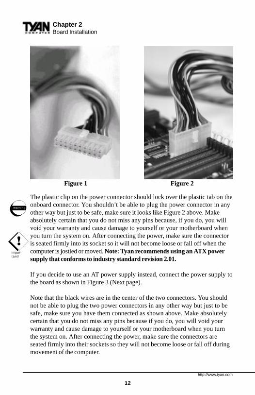
Plug in the power connector as shown.The Tsunami AT has both AT and ATX power supply connectors. The softpower on/off functions of Windows 9x and Wake on LAN are only supportedwith ATX power supplies. The photos on the next page show the ATX powerconnector before (Figure 1) and after (Figure 2) it has been plugged in.
!important!
INS
TALL
http://www.tyan.com
12
Chapter 2Board Installation
The plastic clip on the power connector should lock over the plastic tab on theonboard connector. You shouldn’t be able to plug the power connector in anyother way but just to be safe, make sure it looks like Figure 2 above. Makeabsolutely certain that you do not miss any pins because, if you do, you willvoid your warranty and cause damage to yourself or your motherboard whenyou turn the system on. After connecting the power, make sure the connectoris seated firmly into its socket so it will not become loose or fall off when thecomputer is jostled or moved. Note: Tyan recommends using an ATX powersupply that conforms to industry standard revision 2.01.
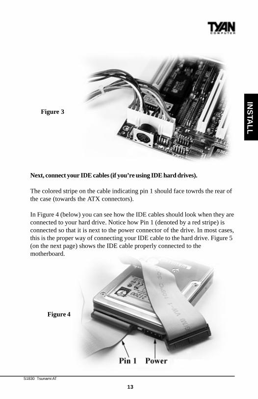
If you decide to use an AT power supply instead, connect the power supply tothe board as shown in Figure 3 (Next page).
Note that the black wires are in the center of the two connectors. You shouldnot be able to plug the two power connectors in any other way but just to besafe, make sure you have them connected as shown above. Make absolutelycertain that you do not miss any pins because if you do, you will void yourwarranty and cause damage to yourself or your motherboard when you turnthe system on. After connecting the power, make sure the connectors areseated firmly into their sockets so they will not become loose or fall off duringmovement of the computer.
Figure 1 Figure 2
!impor-tant!
warning
S1830 Tsunami AT
13
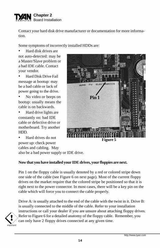
Next, connect your IDE cables (if you’re using IDE hard drives).
The colored stripe on the cable indicating pin 1 should face towrds the rear ofthe case (towards the ATX connectors).
In Figure 4 (below) you can see how the IDE cables should look when they areconnected to your hard drive. Notice how Pin 1 (denoted by a red stripe) isconnected so that it is next to the power connector of the drive. In most cases,this is the proper way of connecting your IDE cable to the hard drive. Figure 5(on the next page) shows the IDE cable properly connected to themotherboard.
INS
TALL
Figure 3
Figure 4
http://www.tyan.com
14
!important!
Contact your hard disk drive manufacturer or documentation for more informa-tion.
Some symptoms of incorrectly installed HDDs are:• Hard disk drives arenot auto-detected: may bea Master/Slave problem ora bad IDE cable. Contactyour vendor.• Hard Disk Drive Failmessage at bootup: maybe a bad cable or lack ofpower going to the drive.• No video or beeps onbootup: usually means thecable is on backwards.• Hard drive lights areconstantly on: bad IDEcable or defective drive ormotherboard. Try anotherHDD.• Hard drives do notpower up: check powercables and cabling. Mayalso be a bad power supply or IDE drive.
Now that you have installed your IDE drives, your floppies are next.
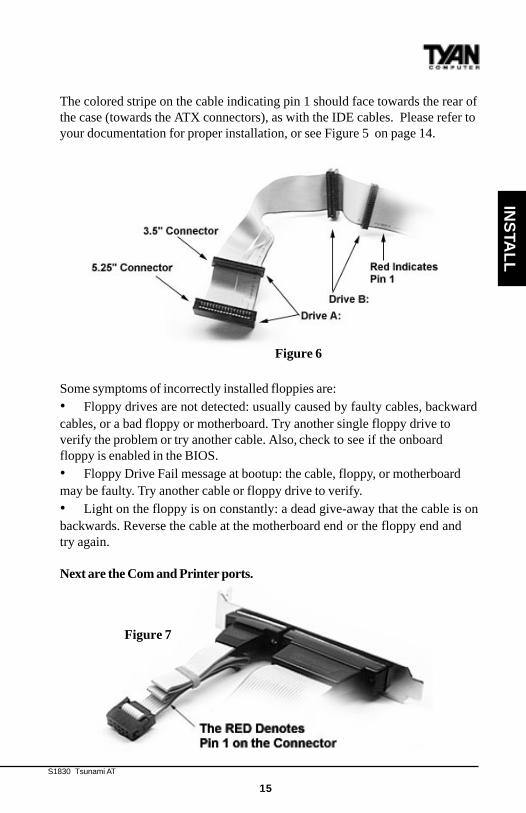
Pin 1 on the floppy cable is usually denoted by a red or colored stripe downone side of the cable (see Figure 6 on next page). Most of the current floppydrives on the market require that the colored stripe be positioned so that it isright next to the power connector. In most cases, there will be a key pin on thecable which will force you to connect the cable properly.
Drive A: is usually attached to the end of the cable with the twist in it. Drive B:is usually connected to the middle of the cable. Refer to your installationinstructions or call your dealer if you are unsure about attaching floppy drives.Refer to Figure 6 for a detailed anatomy of the floppy cable. Remember, youcan only have 2 floppy drives connected at any given time.
Chapter 2Board Installation
Figure 5
Pin 1
S1830 Tsunami AT
15
The colored stripe on the cable indicating pin 1 should face towards the rear ofthe case (towards the ATX connectors), as with the IDE cables. Please refer toyour documentation for proper installation, or see Figure 5 on page 14.
Some symptoms of incorrectly installed floppies are:• Floppy drives are not detected: usually caused by faulty cables, backwardcables, or a bad floppy or motherboard. Try another single floppy drive toverify the problem or try another cable. Also, check to see if the onboardfloppy is enabled in the BIOS.• Floppy Drive Fail message at bootup: the cable, floppy, or motherboardmay be faulty. Try another cable or floppy drive to verify.• Light on the floppy is on constantly: a dead give-away that the cable is onbackwards. Reverse the cable at the motherboard end or the floppy end andtry again.
Next are the Com and Printer ports.
INS
TALL
Figure 6
Figure 7
http://www.tyan.com
16
!important!
Chapter 2Board Installation
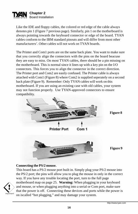
Like the IDE and floppy cables, the colored or red edge of the cable alwaysdenotes pin 1 (Figure 7 previous page). Similarly, pin 1 on the motherboard isalways pointing towards the keyboard connector or edge of the board. TYANcables conform to the IBM standard pinouts and will differ from most othermanufacturers’. Other cables will not work on TYAN boards.
The Printer and Com1 ports are on the same back plate. You want to make surethat you correctly align the connectors with the pins on the board beacusethey are easy to miss. On most TYAN cables, there should be a pin missing onthe motherboard. This is normal since it lines up with a key pin on the I/Oconnectors. This forces you to align the connector in the correct direction.The Printer port and Com2 are easily confused. The Printer cable is alwaysattached with Com1 (Figure 8) where Com2 is supplied seperately on a secondback plate (Figure 9). Remember: Only TYAN cables will work on thismotherboard. If you are using an existing case with old cables, your systemmay not function properly. Use TYAN-approved connectors to ensurecompatibility.
Connecting the PS/2 mouse.This board has a PS/2 mouse port built in. Simply plug your PS/2 mouse intothe PS/2 port; the pins will allow you to plug the mouse in only in the correctway. If you have any trouble locating the port, turn to the full pagemotherboard map on page 25. Warning: When plugging in your keyboardand mouse, or when plugging anything into a serial or Com port, make surethat the power is off. Connecting these devices and ports while the power ison iscalled “hot plugging,” and may damage your system.
Figure 8
Figure 9
S1830 Tsunami AT
17
INS
TALL
Installing your add-in cards is relatively simple but...there are a few rules you need to follow when plugging in a card. In order toassure proper operation and a quick installation, adhere to these guidelines:• If you are going to install a PCI-Bus interface card on your system,
be aware that any one of the two PCI slots can support a Master or Slavedevice.
• NEVER force a card into a slot. If it doesn’t fit, look at the socket on thecomputer to make sure there are no wires or other obstructions to the slot.
• NEVER plug an ISA card into a PCI slot or a PCI card in an ISA slot. Youwill void your warranty and damage your system board if you do this.
• When plugging the card in, especially when installing long cards, try topush the entire card in at one time. Don’t force one end of the card into thesocket first and then the other. This will create a rocking motion betweenthe card and the slot and it will damage the pins within the socket.
• Make sure that the cards are seated securely into the slots.
• Before turning on the system, make sure no cards are touchingeach other to prevent shorting.
If you follow these basic guidelines, there shouldn’t be any problems withinstallation. However, if you do encounter any problems, have a qualifiedprofessional install your cards for you or contact your card manufacturer.
Remember, always read the manuals and installation notes that come with theadapter cards. They contain important information which will help you installthe components right, the first time.
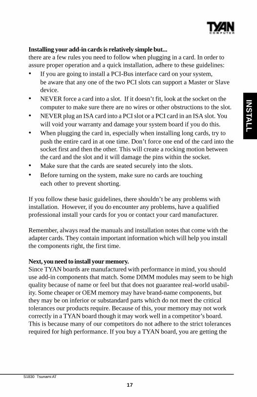
Next, you need to install your memory.Since TYAN boards are manufactured with performance in mind, you shoulduse add-in components that match. Some DIMM modules may seem to be highquality because of name or feel but that does not guarantee real-world usabil-ity. Some cheaper or OEM memory may have brand-name components, butthey may be on inferior or substandard parts which do not meet the criticaltolerances our products require. Because of this, your memory may not workcorrectly in a TYAN board though it may work well in a competitor’s board.This is because many of our competitors do not adhere to the strict tolerancesrequired for high performance. If you buy a TYAN board, you are getting the
http://www.tyan.com
18
!important!
Chapter 2Board Installation
best system available. To make installation easy and trouble free, get highquality parts. Some brands we recommend are Advantage Memory, CorsairMicrosystems, Millenium, Kingston Memory, QesTec Incorporated, Unigen,Micron Technology, and Crucial Technology. These DIMMs have proven tobe very stable on our boards and perform extremely well.
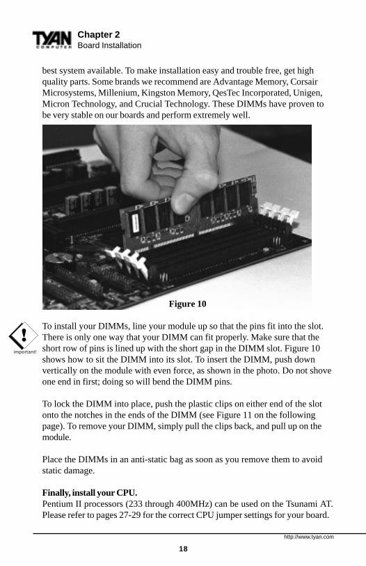
Figure 10
To install your DIMMs, line your module up so that the pins fit into the slot.There is only one way that your DIMM can fit properly. Make sure that theshort row of pins is lined up with the short gap in the DIMM slot. Figure 10shows how to sit the DIMM into its slot. To insert the DIMM, push downvertically on the module with even force, as shown in the photo. Do not shoveone end in first; doing so will bend the DIMM pins.
To lock the DIMM into place, push the plastic clips on either end of the slotonto the notches in the ends of the DIMM (see Figure 11 on the followingpage). To remove your DIMM, simply pull the clips back, and pull up on themodule.
Place the DIMMs in an anti-static bag as soon as you remove them to avoidstatic damage.
Finally, install your CPU.Pentium II processors (233 through 400MHz) can be used on the Tsunami AT.Please refer to pages 27-29 for the correct CPU jumper settings for your board.
S1830 Tsunami AT
19
INS
TALL
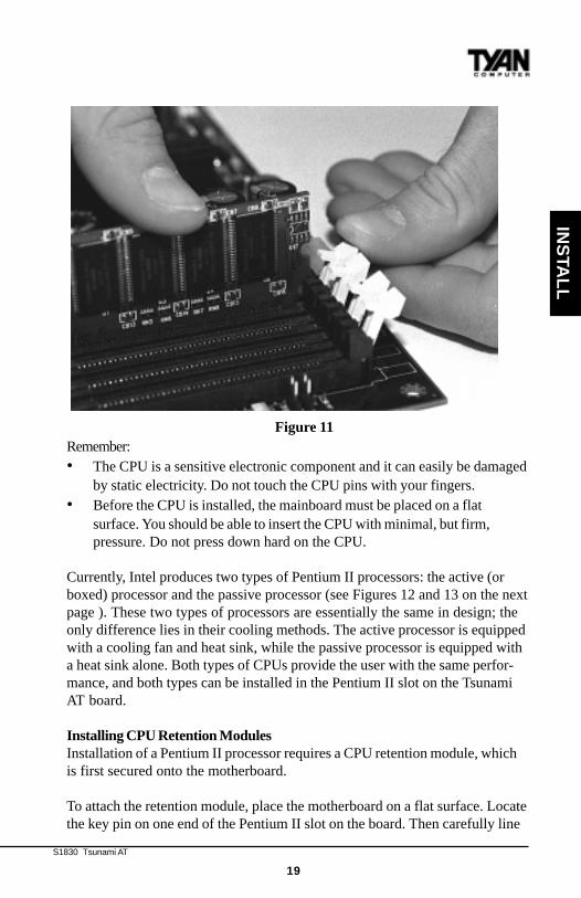
Remember:• The CPU is a sensitive electronic component and it can easily be damaged
by static electricity. Do not touch the CPU pins with your fingers.• Before the CPU is installed, the mainboard must be placed on a flat
surface. You should be able to insert the CPU with minimal, but firm,pressure. Do not press down hard on the CPU.
Currently, Intel produces two types of Pentium II processors: the active (orboxed) processor and the passive processor (see Figures 12 and 13 on the nextpage ). These two types of processors are essentially the same in design; theonly difference lies in their cooling methods. The active processor is equippedwith a cooling fan and heat sink, while the passive processor is equipped witha heat sink alone. Both types of CPUs provide the user with the same perfor-mance, and both types can be installed in the Pentium II slot on the TsunamiAT board.
Installing CPU Retention ModulesInstallation of a Pentium II processor requires a CPU retention module, whichis first secured onto the motherboard.
To attach the retention module, place the motherboard on a flat surface. Locatethe key pin on one end of the Pentium II slot on the board. Then carefully line
Figure 11
http://www.tyan.com
20
Pentium II Slot Connector and Key Pin
Figure 14
Chapter 2Board Installation
!impor-tant!
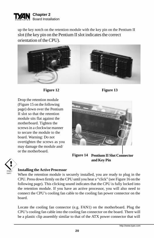
up the key notch on the retention module with the key pin on the Pentium IIslot (the key pin on the Pentium II slot indicates the correctorientation of the CPU).
Figure 12 Figure 13
Drop the retention module(Figure 15 on the followingpage) down over the PentiumII slot so that the retentionmodule sits flat against themotherboard. Tighten thescrews in a clockwise mannerto secure the module to theboard. Warning: Do notovertighten the screws as youmay damage the module and/or the motherboard.
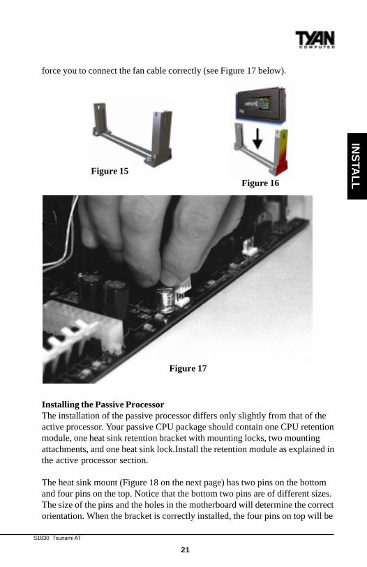
Installing the Active ProcessorWhen the retention module is securely installed, you are ready to plug in theCPU. Press down firmly on the CPU until you hear a “click” (see Figure 16 on thefollowing page). This clicking sound indicates that the CPU is fully locked intothe retention module. If you have an active processor, you will also need toconnect the CPU’s cooling fan cable to the cooling fan power connector on theboard.
Locate the cooling fan connector (e.g. FAN1) on the motherboard. Plug theCPU’s cooling fan cable into the cooling fan connector on the board. There willbe a plastic clip assembly similar to that of the ATX power connector that will
S1830 Tsunami AT
21
INS
TALL
force you to connect the fan cable correctly (see Figure 17 below).
I
Installing the Passive ProcessorThe installation of the passive processor differs only slightly from that of theactive processor. Your passive CPU package should contain one CPU retentionmodule, one heat sink retention bracket with mounting locks, two mountingattachments, and one heat sink lock.Install the retention module as explained inthe active processor section.
The heat sink mount (Figure 18 on the next page) has two pins on the bottomand four pins on the top. Notice that the bottom two pins are of different sizes.The size of the pins and the holes in the motherboard will determine the correctorientation. When the bracket is correctly installed, the four pins on top will be
Figure 15Figure 16
Figure 17

http://www.tyan.com
22
Chapter 2Board Installation
right next to the Pentium II CPU slot.
Insert the heat sink mount into the holes on the motherboard. When thebracket is properly inserted into the holes on the motherboard, you will hear aclicking noise.
Align the CPU with the CPU retention module. Make sure the heat sink is linedup with the heat sink mount bracket. If you put the CPU in the wrong way, youmay damage the CPU, the motherboard, and/or the CPU socket. Slowly pressdown on the CPU module until the CPU locks into place. You will hear aclicking noise when the CPU is locked securely into the module.
The heat sink lock (Figure 19)has four notches which willcorrespond to the four pins onthe heat sink mounting bracket.Gently slide the lock betweenthe heat sink and the heat sinkmounting bracket until bothsides of the lock are firmly secured. A clicking sound will be heard when thelock is securely fastened to the heat sink mounting bracket. To remove the lockfrom the heat sink mounting bracket, gently press the ends of the locks inwardand pull.
Lock the heat sink mount to the board byinserting the two mounting locks (Figure 20) intothe pins of the heat sink mounting bracket whichare now below the mainboard. There will be aclick when the locks are securely fastened.
Figure 18
Figure 19
Figure 20
S1830 Tsunami AT
23
INS
TALL
Removing the CPU.To remove the CPU, move the locks to the center of the CPU. A click will beheard when the CPU has been unlocked. Gently pull up on the CPU, takingcare not to bend the motherboard or the CPU retention module.
To remove the lock from the retention module, gently press the ends of thelocks inward and pull.
You are done.Other than checking the jumper settings and cable connections and puttingthe case back on, you are done. Installing a new motherboard may sounddifficult, but by following these directions, you should have a fairly uneventfultime installing our products. If you do encounter problems, your dealer will beable to help you, or you can consult one of our many technical supportresources (see page 8).
Setting Jumpers
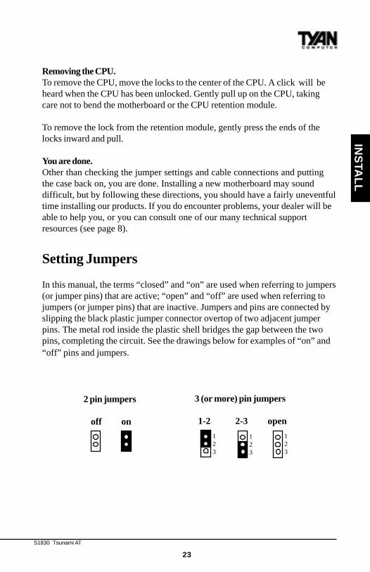
In this manual, the terms “closed” and “on” are used when referring to jumpers(or jumper pins) that are active; “open” and “off” are used when referring tojumpers (or jumper pins) that are inactive. Jumpers and pins are connected byslipping the black plastic jumper connector overtop of two adjacent jumperpins. The metal rod inside the plastic shell bridges the gap between the twopins, completing the circuit. See the drawings below for examples of “on” and“off” pins and jumpers.
2 pin jumpers
off on
3 (or more) pin jumpers
1-2 2-3 open
123
123
123
http://www.tyan.com
24
Quick References for Jumpers
The tables on the following pages will help you set the jumpers for CPU speed,InfraRed, and external connector pin assignments, among others. The miniaturemotherboard maps will help you locate the jumpers on your board. A full-pagemap of the motherboard can be found on the facing page.
Chapter 3Onboard Resource Settings
chap
ter 3
Onboard Resource Settings
S1830 Tsunami AT
25
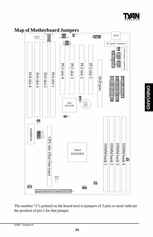
The number “1”s printed on the board next to jumpers of 3 pins or more indicatethe position of pin 1 for that jumper.
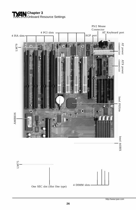
Map of Motherboard Jumpers
ON
BO
AR
D
PC
I slot 2
PC
I slot 3 AG
P port
PC
I slot 4
PC
I slot 1
DIM
M bank 3
DIM
M bank 4
DIM
M bank 2
DIM
M bank 1
CP
U slot (S
lot One type)
Intel82371EB
Intel82443BX
Sec
onda
ry I
DE
con
nect
or
Prim
ary
IDE
con
nect
or
Flo
ppy
driv
e co
nnec
tor
Kbrd
NationalLM75
NationalLM79
AT
X p
ow
er co
nn
ecto
r
AT power connector
ISA
slot 4
ISA
slot 3
ISA
slot 2
ISA
slot 1
AM
IBIO
S
J8
JP15
JP14
JP1
JP8JP9JP10JP11
1
FA
N1
1FAN21
FAN3
JP13
JP6
J9J10
JP3JP4
JP2
CO
N3
CO
N2
CO
M1
CO
M2
LPT
1 1 1
11
55
J6
1
11
3 voltlithiumbattery
http://www.tyan.com
26
Chapter 3Onboard Resource Settings
4 DIMM slots
AM
IBIO
S
AGP port
Inte
l PIIX
4e
4 ISA slots4 PCI slots
Inte
l 44
3B
XL
M7
5L
M7
9
One SEC slot (Slot One type)
AT Keyboard port
AT
X p
ow
er
con
ne
ctor
AT
po
we
rco
nn
ecto
r
PS/2 MouseConnector
S1830 Tsunami AT
27
ON
BO
AR
D
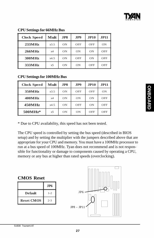
CPU Settings for 66MHz Bus
CPU Settings for 100MHz Bus
* Due to CPU availability, this speed has not been tested.
The CPU speed is controlled by setting the bus speed (described in BIOSsetup) and by setting the multiplier with the jumpers described above that areappropriate for your CPU and memory. You must have a 100MHz processor torun at a bus speed of 100MHz. Tyan does not recommend and is not respon-sible for functionality or damage to components caused by operating a CPU,memory or any bus at higher than rated speeds (overclocking).
CMOS Reset
deepSkcolC tluM 8PJ 9PJ 01PJ 11PJ
zHM332 5.3x NO FFO FFO NO
zHM662 4x NO NO NO FFO
zHM003 5.4x NO FFO NO FFO
zHM333 5x NO NO FFO FFO
deepSkcolC tluM 8PJ 9PJ 01PJ 11PJ
zHM053 5.3x NO FFO FFO NO
zHM004 4x NO NO NO FFO
zHM054 5.4x NO FFO NO FFO
*zHM005 5x NO NO FFO FFO
6PJ
tluafeD 2-1
SOMCteseR 3-2
JP8 - JP11
JP6
http://www.tyan.com
28
Hardware CMOS & Password Reset
If you have been locked out of your system because you forgot your pass-word or set the CMOS incorrectly, follow the instructions below.
1. Power off the system2. Set jumper JP6 to pins 2 and 3 (see previous page for location of JP6).3. Wait for 2 seconds, then return jumper JP6 to pins 1 and 2.4. Power on the system again.
By following this procedure, you will erase your password and reset theCMOS to the BIOS defaults.InfraRed/Floppy Drive Settings
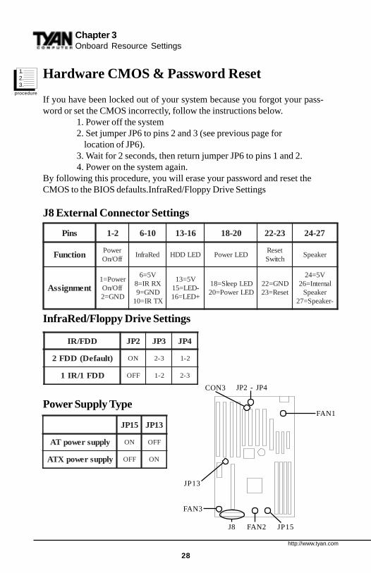
J8 External Connector Settings
InfraRed/Floppy Drive Settings
Power Supply Type
sniP 2-1 01-6 61-31 02-81 32-22 72-42
noitcnuF rewoPffO/nO
deRarfnI DELDDH DELrewoPteseRhctiwS
rekaepS
tnemngissArewoP=1
ffO/nODNG=2
V5=6XRRI=8DNG=9XTRI=01
V5=31-DEL=51+DEL=61
DELpeelS=81DELrewoP=02
DNG=22teseR=32
V5=42lanretnI=62
rekaepS-rekaepS=72
Chapter 3Onboard Resource Settings
DDF/RI 2PJ 3PJ 4PJ
)tluafeD(DDF2 NO 3-2 2-1
DDF1/RI1 FFO 2-1 3-2
FAN3
FAN1
FAN2J8 JP15
JP2 - JP4
51PJ 31PJ
ylppusrewopTA NO FFO
ylppusrewopXTA FFO NO
CON3
procedure
1.2.3.
JP13
S1830 Tsunami AT
29
ON
BO
AR
D
Other Pin Assignments
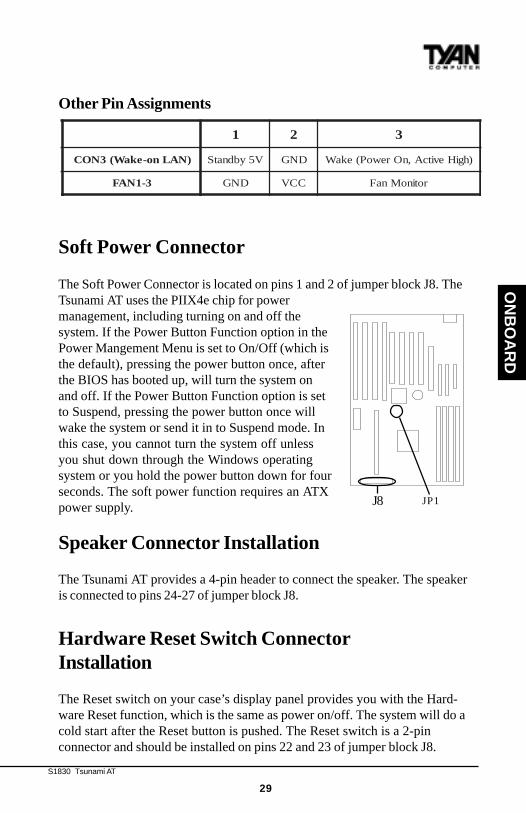
Soft Power Connector
The Soft Power Connector is located on pins 1 and 2 of jumper block J8. TheTsunami AT uses the PIIX4e chip for powermanagement, including turning on and off thesystem. If the Power Button Function option in thePower Mangement Menu is set to On/Off (which isthe default), pressing the power button once, afterthe BIOS has booted up, will turn the system onand off. If the Power Button Function option is setto Suspend, pressing the power button once willwake the system or send it in to Suspend mode. Inthis case, you cannot turn the system off unlessyou shut down through the Windows operatingsystem or you hold the power button down for fourseconds. The soft power function requires an ATXpower supply.
Speaker Connector Installation
The Tsunami AT provides a 4-pin header to connect the speaker. The speakeris connected to pins 24-27 of jumper block J8.
Hardware Reset Switch ConnectorInstallation
The Reset switch on your case’s display panel provides you with the Hard-ware Reset function, which is the same as power on/off. The system will do acold start after the Reset button is pushed. The Reset switch is a 2-pinconnector and should be installed on pins 22 and 23 of jumper block J8.
J8
1 2 3
)NALno-ekaW(3NOC V5ybdnatS DNG )hgiHevitcA,nOrewoP(ekaW
3-1NAF DNG CCV rotinoMnaF
JP1
http://www.tyan.com
30
Chapter 3Onboard Resource Settings
!impor-tant!
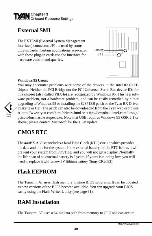
External SMI
The EXTSMI (External System ManagementInterface) connector, JP1, is used by someplug-in cards. Certain applications associatedwith these plug-in cards use the interface forhardware control and queries.
Windows 95 Users:You may encounter problems with some of the devices in the Intel 82371EBchipset. Neither the PCI Bridge nor the PCI Universal Serial Bus device IDs forthis chipset (also called PIIX4e) are recognized by Windows 95. This is a soft-ware problem, not a hardware problem, and can be easily remedied by eitherupgrading to Windows 98 or installing the 82371EB patch on the Tyan BX DriverDiskette or CD. The patch can also be downloaded from the Tyan web or ftp siteat http://www.tyan.com/html/drivers.html or at ftp://download.intel.com/design/pcisets/busmastr/setupex.exe. Note that USB requires Windows 95 OSR 2.1 orabove; please contact Microsoft for the USB update.
CMOS RTC
The 440BX AGPset includes a Real Time Clock (RTC) circuit, which providesthe date and time for the system. If the external battery for the RTC is low, it willprevent your system from POSTing, and you will not get a display. Normallythe life span of an external battery is 2 years. If yours is running low, you willneed to replace it with a new 3V lithium battery (Sony CR2032).
Flash EEPROM
The Tsunami AT uses flash memory to store BIOS programs. It can be updatedas new versions of the BIOS become available. You can upgrade your BIOSeasily using the Flash Writer Utility (see page 61).
RAM Installation
The Tsunami AT uses a 64-bit data path from memory to CPU and can accom-
JP1
Battery
S1830 Tsunami AT
31
ON
BO
AR
D
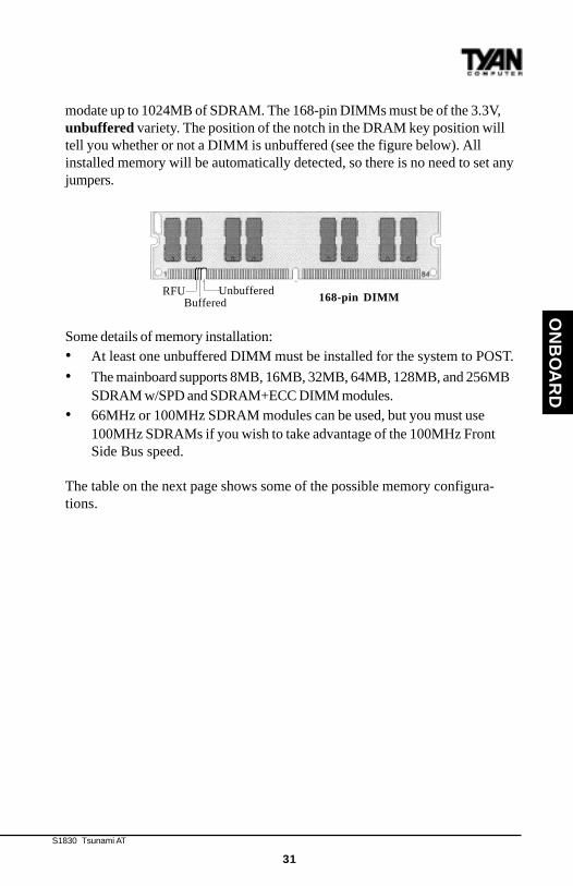
modate up to 1024MB of SDRAM. The 168-pin DIMMs must be of the 3.3V,unbuffered variety. The position of the notch in the DRAM key position willtell you whether or not a DIMM is unbuffered (see the figure below). Allinstalled memory will be automatically detected, so there is no need to set anyjumpers.
Some details of memory installation:• At least one unbuffered DIMM must be installed for the system to POST.
• The mainboard supports 8MB, 16MB, 32MB, 64MB, 128MB, and 256MBSDRAM w/SPD and SDRAM+ECC DIMM modules.
• 66MHz or 100MHz SDRAM modules can be used, but you must use100MHz SDRAMs if you wish to take advantage of the 100MHz FrontSide Bus speed.
The table on the next page shows some of the possible memory configura-tions.
RFUBuffered
Unbuffered168-pin DIMM

http://www.tyan.com
32
Cache Memory
Penitum II processors have the L2 (Level 2) cache built into their architecture,so there is no need for an L2 cache on the motherboard. The Pentium IIprocessor has a phsyical L2 cache size of 512KB and a cacheable memory areaof 512MB.
Frequently Asked Questions
Q: Why don’t I get a display after I put in my old DIMM module?
Chapter 3Onboard Resource Settings
MMID1knaB
MMID2knaB
MMID3knaB
MMID4knaB
latoT
1xBM8 0 0 0 BM8
1xBM8 1xBM8 0 0 BM61
1xBM8 1xBM8 1xBM8 0 BM42
1xBM61 1xBM8 1xBM8 0 BM23
1xBM61 1xBM61 1xBM8 1xBM8 BM84
1xBM61 1xBM61 1xBM61 0 BM84
1xBM23 1xBM61 1xBM61 0 BM46
1xBM23 1xBM23 1xBM61 BM61 BM69
1xBM23 1xBM23 1xBM23 BM23 BM821
1xBM46 1xBM23 1xBM23 0 BM821
1xBM46 1xBM46 1xBM23 0 BM061
1xBM46 1xBM46 1xBM46 0 BM291
1xBM821 1xBM46 1xBM46 0 BM652
1xBM821 1xBM821 1xBM46 0 BM023
1xBM821 1xBM821 1xBM821 0 BM483
1xBM821 1xBM821 1xBM652 0 BM215
1xBM821 1xBM652 1xBM652 0 BM046
1xBM652 1xBM652 1xBM652 0 BM867
1xBM652 1xBM652 1xBM652 1xBM652 BM4201
S1830 Tsunami AT
33
ON
BO
AR
D
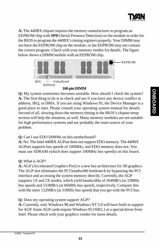
A: The 440BX chipset requires the memory manufacturer to program anEEPROM chip with SPD (Serial Presence Detection) on the module in order forthe BIOS to program the 440BX’s timing registers properly. Your DIMM maynot have the EEPROM chip on the module, or the EEPROM may not containthe correct program. Check with your memory vendor for details. The figurebelow shows a DIMM module with an EEPROM chip.
Q: My system sometimes becomes unstable. How should I check the system?A: The first thing to do is to check and see if you have any device conflict inaddress, IRQ, or DMA. If you are using Windows 95, the Device Manager is agood place to start. Please consult your operating system manual for details.Second of all, slowing down the memory timing in the BIOS’s chipset setupsection will help the situation, as well. Many memory modules are not suitablefor high performance systems and are probably the main source of yourproblem.
Q: Can I use EDO DIMMs on this motherboard?A: No. The Intel 440BX AGPset does not support EDO memory. The 440BXAGPset supports bus speeds of 100MHz, and EDO memory does not. Youmust use SDRAM (which does support 100MHz bus speeds) on this board.
Q: What is AGP?A: AGP (Accelerated Graphics Port) is a new bus architecture for 3D graphics.The AGP slot eliminates the PCI bandwidth bottleneck by bypassing the PCIinterface and accessing the system memory directly. Currently, the AGPsupports 1X and 2X modes, which yield bandwidths of 264MB/s (at 33MHzbus speed) and 533MB/s (at 66MHz bus speed), respectively. Compare thiswith the mere 132MB/s (at 33MHz bus speed) that you get with the PCI bus.
Q: Does my operating system support AGP?A: Currently, only Windows 98 and Windows NT 5.0 will have built-in supportfor AGP. Some AGP cards require Windows 95 OSR2.1 or a special driver fromIntel. Please check with your graphics vendor for more details.
RFUBuffered
Unbuffered
168-pin DIMM
EEPROM
http://www.tyan.com
34
Chapter 4BIOS Configuration
chap
ter 4
BIOS Configuration
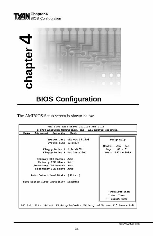
The AMIBIOS Setup screen is shown below.
AMI BIOS EASY SETUP UTILITY Ver.1.16 (c)1998 American Megatrends, Inc. All Rights Reserved Main Advanced Security Exit
System Date Thu Oct 15 1998 Setup Help System Time 12:55:37
Month: Jan - Dec Floppy Drive A 1.44 MB 3½ Day: 01 - 31 Floppy Drive B Not Installed Year: 1901 - 2099
Primary IDE Master Auto Primary IDE Slave Auto Secondary IDE Master Auto Secondary IDE Slave Auto
Auto-Detect Hard Disks [ Enter ]
Boot Sector Virus Protection Disabled
- Previous Item
¯ Next ItemSelect Menu
ESC:Exit Enter:Select F5:Setup Defaults F6:Original Values F10:Save & Exit
®¬
S1830 Tsunami AT
35
BIO
S
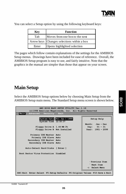
You can select a Setup option by using the following keyboard keys:
The pages which follow contain explanations of the settings for the AMIBIOSSetup menus. Drawings have been included for ease of reference. Overall, theAMIBIOS Setup program is easy to use, and fairly intuitive. Note that thegraphics in the manual are simpler than those that appear on your screen.
Main Setup
Select the AMIBIOS Setup options below by choosing Main Setup from theAMIBIOS Setup main menu. The Standard Setup menu screen is shown below.
AMI BIOS EASY SETUP UTILITY Ver.1.16 (c)1998 American Megatrends, Inc. All Rights Reserved Main Advanced Security Exit
System Date Fri Jan 1 1999 Setup Help System Time 12:55:37
Month: Jan - Dec Floppy Drive A 1.44 MB 3½ Day: 01 - 31 Floppy Drive B Not Installed Year: 1901 - 2099
Primary IDE Master Auto Primary IDE Slave Auto Secondary IDE Master Auto Secondary IDE Slave Auto
Auto-Detect Hard Disks [ Enter ]
Boot Sector Virus Protection Disabled
- Previous Item
¯ Next ItemSelect Menu
ESC:Exit Enter:Select F5:Setup Defaults F6:Original Values F10:Save & Exit
®¬
Key Function
Tab Moves from one box to the next
Arrow keys Changes selections within a box
Enter Opens highlighted selection
http://www.tyan.com
36
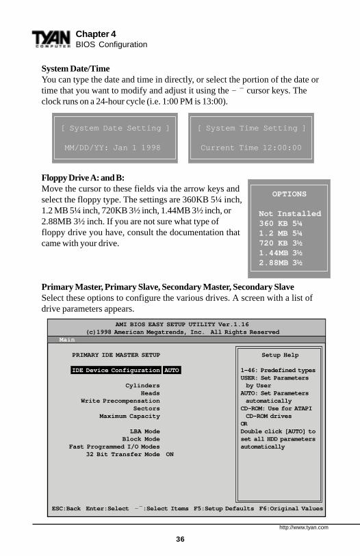
System Date/TimeYou can type the date and time in directly, or select the portion of the date ortime that you want to modify and adjust it using the - ̄ cursor keys. Theclock runs on a 24-hour cycle (i.e. 1:00 PM is 13:00).
Floppy Drive A: and B:Move the cursor to these fields via the arrow keys andselect the floppy type. The settings are 360KB 5¼ inch,1.2 MB 5¼ inch, 720KB 3½ inch, 1.44MB 3½ inch, or2.88MB 3½ inch. If you are not sure what type offloppy drive you have, consult the documentation thatcame with your drive.
Primary Master, Primary Slave, Secondary Master, Secondary SlaveSelect these options to configure the various drives. A screen with a list ofdrive parameters appears.
[ System Date Setting ]
MM/DD/YY: Jan 1 1998
[ System Time Setting ]
Current Time 12:00:00
OPTIONS
Not Installed360 KB 5¼1.2 MB 5¼720 KB 3½1.44MB 3½2.88MB 3½
AMI BIOS EASY SETUP UTILITY Ver.1.16 (c)1998 American Megatrends, Inc. All Rights Reserved Main
PRIMARY IDE MASTER SETUP Setup Help
IDE Device Configuration AUTO 1-46: Predefined typesUSER: Set Parameters
Cylinders by User Heads AUTO: Set Parameters Write Precompensation automatically Sectors CD-ROM: Use for ATAPI Maximum Capacity CD-ROM drives
OR LBA Mode Double click [AUTO] to Block Mode set all HDD parameters Fast Programmed I/O Modes automatically 32 Bit Transfer Mode ON
ESC:Back Enter:Select -¯ :Select Items F5:Setup Defaults F6:Original Values
Chapter 4BIOS Configuration
S1830 Tsunami AT
37
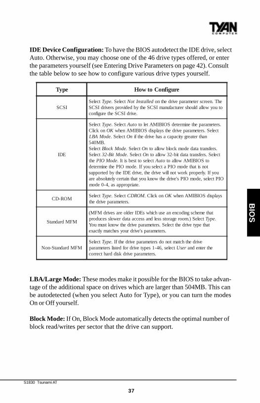
IDE Device Configuration: To have the BIOS autodetect the IDE drive, selectAuto. Otherwise, you may choose one of the 46 drive types offered, or enterthe parameters yourself (see Entering Drive Parameters on page 42). Consultthe table below to see how to configure various drive types yourself.
LBA/Large Mode: These modes make it possible for the BIOS to take advan-tage of the additional space on drives which are larger than 504MB. This canbe autodetected (when you select Auto for Type), or you can turn the modesOn or Off yourself.
Block Mode: If On, Block Mode automatically detects the optimal number ofblock read/writes per sector that the drive can support.
epyT erugifnoCotwoH
ISCStceleS epyT tceleS. dellatsnItoN ehT.neercsretemarapevirdehtno
otuoywolladluohsrerutcafunamISCSehtybdedivorpsrevirdISCS.evirdISCSehterugifnoc
EDI
tceleS epyT tceleS. otuA .sretemarapehtenimretedSOIBIMAtelotnokcilC KO tceleS.sretemarapevirdehtsyalpsidSOIBIMAnehw
edoMABL tceleS. nO nahtretaergyticapacasahevirdehtfi.BM045
tceleS edoMkcolB tceleS. nO .srefsnartatadedomkcolbwollaottceleS edoMtiB-23 tceleS. nO tceleS.srefsnartatadtib-23wollaot
eht edoMOIP tcelesottsebsitI. otuA otSOIBIMAwollaottonsitahtedomOIPatcelesuoyfI.edomOIPehtenimreted
uoyfI.ylreporpkrowtonlliwevirdeht,evirdEDIehtybdetroppusOIPtceles,edomOIPs'evirdehtwonkuoytahtniatrecyletulosbaera
.etairporppasa,4-0edom
MOR-DCtceleS epyT tceleS. MORDC nokcilC. KO syalpsidSOIBIMAnehw
.sretemarapevirdeht
MFMdradnatS
tahtemehcsgnidocnenaesuhcihwsEDIredloerasevirdMFM(tceleS).mooregarotssseldnasseccaatadrewolssecudorp epyT .
tahtepytevirdehttceleS.sretemarapevirdehtwonktsumuoY.sretemaraps'evirdruoysehctamyltcaxe
MFMdradnatS-noNtceleS epyT evirdehthctamtonodsretemarapevirdehtfI.
tceles,64-1sepytevirdrofdetsilsretemarap resU ehtretnedna.sretemarapevirdksiddrahtcerroc
BIO
S
http://www.tyan.com
38
Chapter 4BIOS Configuration
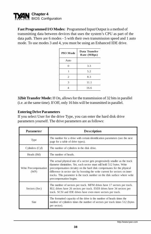
Fast Programmed I/O Modes: Programmed Input/Output is a method oftransmitting data between devices that uses the system’s CPU as part of thedata path. There are 6 modes - 5 with their own transmission speed and 1 automode. To use modes 3 and 4, you must be using an Enhanced IDE drive.
32bit Transfer Mode: If On, allows for the transmission of 32 bits in parallel(i.e. at the same time). If Off, only 16 bits will be transmitted in parallel.
Entering Drive ParametersIf you select User for the drive Type, you can enter the hard disk driveparameters yourself. The drive parameters are as follows:
edoMOIPrefsnarTataD)spBM(etaR
otuA
0 3.3
1 2.5
2 3.8
3 1.11
4 6.61
retemaraP noitpircseD
epyTtxenehtees(sretemarapnoitacifitnediniatrechtiwevirdarofrebmunehT
.)sepytevirdfoelbatarofegap
)lyC(srednilyC .evirdksidehtnisrednilycforebmunehT
)dH(sdaeH .sdaehforebmunehT
noitasnepmocerPetirW)PW(
kcartehtsarellamsylevissergorpstegrotcesafoezislacisyhplautcaehTetirW.setyb215dlohllitstsumrotceshcae,teY.sehsinimidretemaid
lacisyhpehtrofsetasnepmocksiddrahehtnoyrtiucricnoitasnepmocerprenninosrotcesroftnerrucetirwehtgnitsoobybezisrotcesniecnereffid
etirwerehwecafrusksidehtnorebmunkcartehtsiretemarapsihT.skcart.snigebnoitasnepmocerp
)ceS(srotceS.kcartrepsrotces71evahsevirdMFM.kcartrepsrotcesforebmunehT
repsrotces43evahsevirdIDSE.kcartrepsrotces62evahsevirdLLR.kcartrepsrotceseromneveevahsevirdEDIdnaISCS.kcart
eziSehtsemitsdaehforebmunehtsievirdehtfoyticapacdettamrofehT
setyb(215semitkcartrepsrotcesforebmunehtsemitsrednilycforebmun.)rotcesrep
S1830 Tsunami AT
39
BIO
S
Auto-Detect Hard DisksThis option lets the system detect your hard disk(s) automatically for yourconvenience.
Boot Sector Virus ProtectionThe available settings for this option are ‘Enable’ and ‘Disable’.
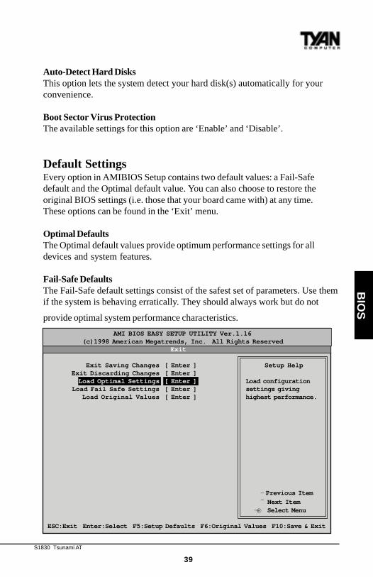
Default SettingsEvery option in AMIBIOS Setup contains two default values: a Fail-Safedefault and the Optimal default value. You can also choose to restore theoriginal BIOS settings (i.e. those that your board came with) at any time.These options can be found in the ‘Exit’ menu.
Optimal DefaultsThe Optimal default values provide optimum performance settings for alldevices and system features.
Fail-Safe DefaultsThe Fail-Safe default settings consist of the safest set of parameters. Use themif the system is behaving erratically. They should always work but do not
provide optimal system performance characteristics.
®¬
AMI BIOS EASY SETUP UTILITY Ver.1.16 (c)1998 American Megatrends, Inc. All Rights Reserved
Exit
Exit Saving Changes [ Enter ] Setup Help Exit Discarding Changes [ Enter ] Load Optimal Settings [ Enter ] Load configuration Load Fail Safe Settings [ Enter ] settings giving Load Original Values [ Enter ] highest performance.
- Previous Item
¯ Next ItemSelect Menu
ESC:Exit Enter:Select F5:Setup Defaults F6:Original Values F10:Save & Exit

http://www.tyan.com
40
Chapter 4BIOS Configuration
Advanced CMOS Setup
The Advanced Setup options included in the AMIBIOS Setup for the TsunamiAT are described in this chapter. Select Advanced Setup from the AMIBIOSSetup main menu to display the Advanced Setup options.
Advanced CMOS Setup Default Settings Chart
Setting Option Optimal Default Fail-Safe Default
Quick B oot Dis abled Dis abled
P rimary Mas ter AR MD Emulated as Auto Auto
P rimary S lave AR MD Emulated as Auto Auto
S econdary Mas ter AR MD Emulated as Auto Auto
S econdary S lave AR MD Emulated as Auto Auto
1s t B oot Device F loppy F loppy
2nd B oot Device 1s t IDE-HDD 1s t IDE-HDD
3rd B oot Device AT AP I CDR OM AT AP I CDR OM
T ry Other B oot Devices Yes Yes
F loppy Acces s Control R ead-Write R ead-Write
Hard Dis k Acces s Control R ead-Write R ead-Write
®¬
AMI BIOS EASY SETUP UTILITY Ver.1.16 (c)1998 American Megatrends, Inc. All Rights Reserved Advanced
Advanced CMOS Setup [ Enter ] Setup Help Advanced Chipset Setup [ Enter ] Power Management Setup [ Enter ] Advanced CMOS setup Plug and Play Setup [ Enter ] for configuring system Peripheral Setup [ Enter ] options Change Language Setting English
- Previous Item
¯ Next ItemSelect Menu
ESC:Exit Enter:Select F5:Setup Defaults F6:Original Values F10:Save & Exit
S1830 Tsunami AT
41
BIO
S
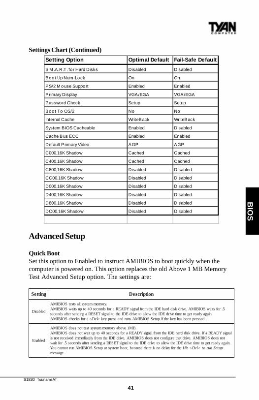
Settings Chart (Continued)
Advanced Setup
Quick BootSet this option to Enabled to instruct AMIBIOS to boot quickly when thecomputer is powered on. This option replaces the old Above 1 MB MemoryTest Advanced Setup option. The settings are:
gnitteS noitpircseD
delbasiD
.yromemmetsysllastsetSOIBIMA5.rofstiawSOIBIMA.evirdksiddrahEDIehtmorflangisYDAERarofsdnoces04otpustiawSOIBIMA
.niagaydaertegotemitevirdEDIehtwollaotevirdEDIehtotlangisTESERagnidnesretfasdnoces.desserpneebsahyekehtfiputeSSOIBIMAsnurdnasserpyek>leD<arofskcehcSOIBIMA
delbanE
.BM1evobayromemmetsystsettonseodSOIBIMAlangisYDAERafI.evirdksiddrahEDIehtmorflangisYDAERarofsdnoces04otputiawtonseodSOIBIMA
tonseodSOIBIMA.evirdtahterugifnoctonseodSOIBIMA,evirdEDIehtmorfyletaidemmideviecertonsi.niagaydaertegotemitevirdEDIehtwollaotevirdEDIehtotlangisTESERagnidnesretfasdnoces5.roftiaw
ehtrofyaledonsierehtesuaceb,toobmetsystaputeSSOIBIMAnurtonnacuoY puteSnurot>leD<tiH.egassem
Setting Option Optimal Default Fail-Safe Default
S .M.A.R .T . for Hard Dis ks Dis abled Dis abled
B oot Up Num-Lock On On
P S /2 Mous e S upport E nabled E nabled
P rimary Dis play VGA/EGA VGA/EGA
P as s word Check S etup S etup
B oot T o OS /2 No No
Internal Cache WriteB ack WriteB ack
S ys tem B IOS Cacheable E nabled Dis abled
Cache B us E CC E nabled E nabled
Default P rimary Video AGP AGP
C000,16K S hadow Cached Cached
C400,16K S hadow Cached Cached
C800,16K S hadow Dis abled Dis abled
CC00,16K S hadow Dis abled Dis abled
D000,16K S hadow Dis abled Dis abled
D400,16K S hadow Dis abled Dis abled
D800,16K S hadow Dis abled Dis abled
DC00,16K S hadow Dis abled Dis abled
http://www.tyan.com
42
Chapter 4BIOS Configuration
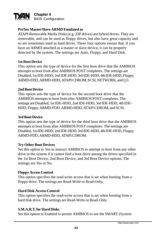
Pri/Sec Master/Slave ARMD Emulated asATAPI Removable Media Disks (e.g. ZIP drives) are hybrid drives. They areremovable, and can be used as floppy drives, but also have great capacity andso are sometimes used as hard drives. These four options ensure that, if youhave an ARMD attached as a master or slave device, it can be properlydetected by the system. The settings are Auto, Floppy, and Hard Disk.
1st Boot DeviceThis option sets the type of device for the first boot drive that the AMIBIOSattempts to boot from after AMIBIOS POST completes. The settings areDisabled, 1st IDE-HDD, 2nd IDE-HDD, 3rd IDE-HDD, 4th IDE-HDD, Floppy,ARMD-FDD, ARMD-HDD, ATAPI CDROM, SCSI, NETWORK, and I
2O.
2nd Boot DeviceThis option sets the type of device for the second boot drive that theAMIBIOS attempts to boot from after AMIBIOS POST completes. Thesettings are Disabled, 1st IDE-HDD, 2nd IDE-HDD, 3rd IDE-HDD, 4th IDE-HDD, Floppy, ARMD-FDD, ARMD-HDD, ATAPI CDROM, and SCSI.
3rd Boot DeviceThis option sets the type of device for the third boot drive that the AMIBIOSattempts to boot from after AMIBIOS POST completes. The settings areDisabled, 1st IDE-HDD, 2nd IDE-HDD, 3rd IDE-HDD, 4th IDE-HDD, Floppy,ARMD-FDD, ARMD-HDD, ATAPI CDROM.
Try Other Boot DevicesSet this option to Yes to instruct AMIBIOS to attempt to boot from any otherdrive in the system if it cannot find a boot drive among the drives specified inthe 1st Boot Device, 2nd Boot Device, and 3rd Boot Device options. Thesettings are Yes or No.
Floppy Access ControlThis option specifies the read-write access that is set when booting from afloppy drive. The settings are Read-Write or Read-Only.
Hard Disk Access ControlThis option specifies the read-write access that is set when booting from ahard disk drive. The settings are Read-Write or Read-Only.
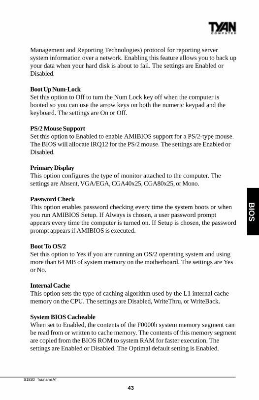
S.M.A.R.T. for Hard DisksSet this option to Enabled to permit AMIBIOS to use the SMART (System
S1830 Tsunami AT
43
BIO
S
Management and Reporting Technologies) protocol for reporting serversystem information over a network. Enabling this feature allows you to back upyour data when your hard disk is about to fail. The settings are Enabled orDisabled.
Boot Up Num-LockSet this option to Off to turn the Num Lock key off when the computer isbooted so you can use the arrow keys on both the numeric keypad and thekeyboard. The settings are On or Off.
PS/2 Mouse SupportSet this option to Enabled to enable AMIBIOS support for a PS/2-type mouse.The BIOS will allocate IRQ12 for the PS/2 mouse. The settings are Enabled orDisabled.
Primary DisplayThis option configures the type of monitor attached to the computer. Thesettings are Absent, VGA/EGA, CGA40x25, CGA80x25, or Mono.
Password CheckThis option enables password checking every time the system boots or whenyou run AMIBIOS Setup. If Always is chosen, a user password promptappears every time the computer is turned on. If Setup is chosen, the passwordprompt appears if AMIBIOS is executed.
Boot To OS/2Set this option to Yes if you are running an OS/2 operating system and usingmore than 64 MB of system memory on the motherboard. The settings are Yesor No.
Internal CacheThis option sets the type of caching algorithm used by the L1 internal cachememory on the CPU. The settings are Disabled, WriteThru, or WriteBack.
System BIOS CacheableWhen set to Enabled, the contents of the F0000h system memory segment canbe read from or written to cache memory. The contents of this memory segmentare copied from the BIOS ROM to system RAM for faster execution. Thesettings are Enabled or Disabled. The Optimal default setting is Enabled.
http://www.tyan.com
44
Chapter 4BIOS Configuration
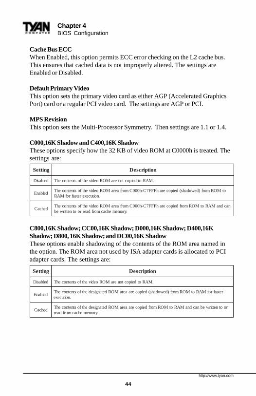
Cache Bus ECCWhen Enabled, this option permits ECC error checking on the L2 cache bus.This ensures that cached data is not improperly altered. The settings areEnabled or Disabled.
Default Primary VideoThis option sets the primary video card as either AGP (Accelerated GraphicsPort) card or a regular PCI video card. The settings are AGP or PCI.
MPS RevisionThis option sets the Multi-Processor Symmetry. Then settings are 1.1 or 1.4.
C000,16K Shadow and C400,16K ShadowThese options specify how the 32 KB of video ROM at C0000h is treated. Thesettings are:
C800,16K Shadow; CC00,16K Shadow; D000,16K Shadow; D400,16KShadow; D800, 16K Shadow; and DC00,16K ShadowThese options enable shadowing of the contents of the ROM area named inthe option. The ROM area not used by ISA adapter cards is allocated to PCIadapter cards. The settings are:
gnitteS noitpircseD
delbasiD .MARotdeipoctoneraMORoedivehtfostnetnocehT
delbanEotMORmorf)dewodahs(deipocerahFFF7C-h000CmorfaeraMORoedivehtfostnetnocehT
.noitucexeretsafrofMAR
dehcaCnacdnaMARotMORmorfdeipocerahFFF7C-h000CmorfaeraMORoedivehtfostnetnocehT
.yromemehcacmorfdaerrootnettirweb
gnitteS noitpircseD
delbasiD .MARotdeipoctoneraMORoedivehtfostnetnocehT
delbanEretsafrofMARotMORmorf)dewodahs(deipoceraaeraMORdetangisedehtfostnetnocehT
.noitucexe
dehcaCrootnettirwebnacdnaMARotMORmorfdeipoceraaeraMORdetangisedehtfostnetnocehT
.yromemehcacmorfdaer
S1830 Tsunami AT
45
BIO
S
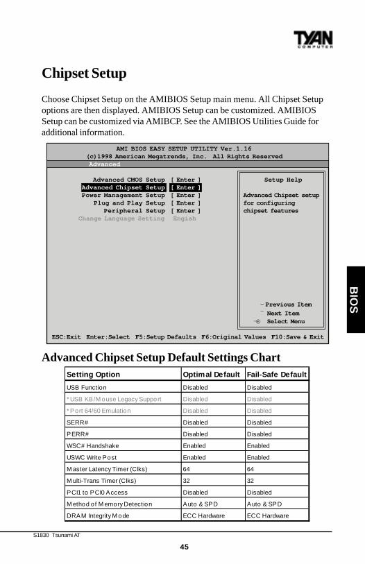
Chipset Setup
Choose Chipset Setup on the AMIBIOS Setup main menu. All Chipset Setupoptions are then displayed. AMIBIOS Setup can be customized. AMIBIOSSetup can be customized via AMIBCP. See the AMIBIOS Utilities Guide foradditional information.
Advanced Chipset Setup Default Settings Chart
®¬
AMI BIOS EASY SETUP UTILITY Ver.1.16 (c)1998 American Megatrends, Inc. All Rights Reserved Advanced
Advanced CMOS Setup [ Enter ] Setup Help Advanced Chipset Setup [ Enter ] Power Management Setup [ Enter ] Advanced Chipset setup Plug and Play Setup [ Enter ] for configuring Peripheral Setup [ Enter ] chipset features Change Language Setting Engish
- Previous Item
¯ Next ItemSelect Menu
ESC:Exit Enter:Select F5:Setup Defaults F6:Original Values F10:Save & Exit
Setting Option Optimal Default Fail-Safe Default
US B F unction Dis abled Dis abled
* US B KB /Mous e Legacy S upport Dis abled Dis abled
* P ort 64/60 Emulation Dis abled Dis abled
S E R R # Dis abled Dis abled
P ER R # Dis abled Dis abled
WS C# Hands hake Enabled Enabled
US WC Write P os t Enabled Enabled
Mas ter Latency T imer (Clks ) 64 64
Multi-T rans T imer (Clks ) 32 32
P CI1 to P CI0 Acces s Dis abled Dis abled
Method of Memory Detection Auto & S P D Auto & S P D
DR AM Integrity Mode ECC Hardware ECC Hardware
http://www.tyan.com
46
Chapter 4BIOS Configuration
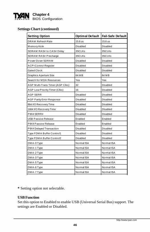
Settings Chart (continued)
* Setting option not selectable.
USB FunctionSet this option to Enabled to enable USB (Universal Serial Bus) support. Thesettings are Enabled or Disabled.
Setting Option Optimal Default Fail-Safe Default
DR AM R efres h R ate 15.6 us 15.6 us
Memory Hole Dis abled Dis abled
S DR AM R AS # to CAS # Delay 3S CLKs 3S CLKs
S DR AM R AS # P recharge 3S CLKs 3S CLKs
P ower Down S DR AM Dis abled Dis abled
ACP I Control R egis ter Dis abled Dis abled
Gated Clock Dis abled Dis abled
Graphics Aperture S ize 64 MB 64 MB
S earch for MDA R es ources Yes Yes
AGP Multi-T rans T imer (AGP Clks ) 32 Dis abled
AGP Low-P riority T imer (Clks ) 16 Dis abled
AGP S ER R Dis abled Dis abled
AGP P arity E rror R es pons e Dis abled Dis abled
8bit I/O R ecovery T ime Dis abled Dis abled
16bit I/O R ecovery T ime Dis abled Dis abled
P IIX4 S E R R # Dis abled Dis abled
US B P as s ive R eleas e Enabled Enabled
P IIX4 P as s ive R eleas e Enabled Enabled
P IIX4 Delayed T rans action Dis abled Dis abled
T ype F DMA B uffer Control1 Dis abled Dis abled
T ype F DMA B uffer Control2 Dis abled Dis abled
DMA-0 T ype Normal IS A Normal IS A
DMA-1 T ype Normal IS A Normal IS A
DMA-2 T ype Normal IS A Normal IS A
DMA-3 T ype Normal IS A Normal IS A
DMA-5 T ype Normal IS A Normal IS A
DMA-6 T ype Normal IS A Normal IS A
DMA-7 T ype Normal IS A Normal IS A
S1830 Tsunami AT
47
BIO
S
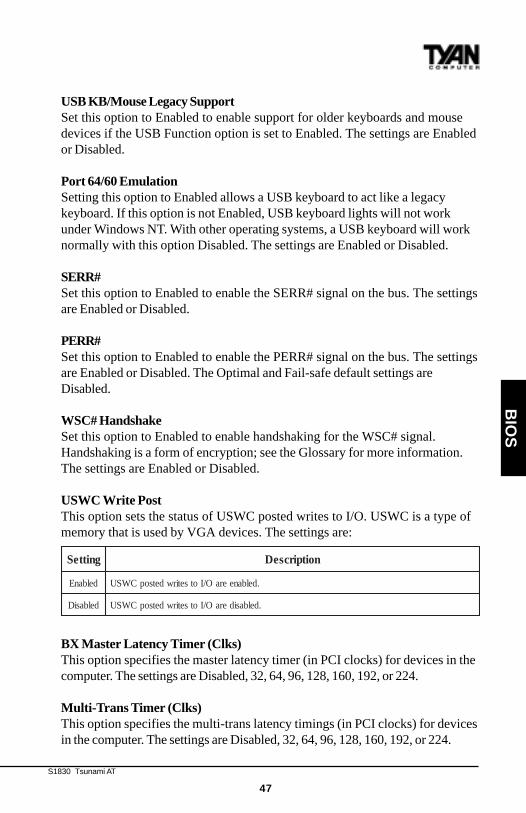
USB KB/Mouse Legacy SupportSet this option to Enabled to enable support for older keyboards and mousedevices if the USB Function option is set to Enabled. The settings are Enabledor Disabled.
Port 64/60 EmulationSetting this option to Enabled allows a USB keyboard to act like a legacykeyboard. If this option is not Enabled, USB keyboard lights will not workunder Windows NT. With other operating systems, a USB keyboard will worknormally with this option Disabled. The settings are Enabled or Disabled.
SERR#Set this option to Enabled to enable the SERR# signal on the bus. The settingsare Enabled or Disabled.
PERR#Set this option to Enabled to enable the PERR# signal on the bus. The settingsare Enabled or Disabled. The Optimal and Fail-safe default settings areDisabled.
WSC# HandshakeSet this option to Enabled to enable handshaking for the WSC# signal.Handshaking is a form of encryption; see the Glossary for more information.The settings are Enabled or Disabled.
USWC Write PostThis option sets the status of USWC posted writes to I/O. USWC is a type ofmemory that is used by VGA devices. The settings are:
BX Master Latency Timer (Clks)This option specifies the master latency timer (in PCI clocks) for devices in thecomputer. The settings are Disabled, 32, 64, 96, 128, 160, 192, or 224.
Multi-Trans Timer (Clks)This option specifies the multi-trans latency timings (in PCI clocks) for devicesin the computer. The settings are Disabled, 32, 64, 96, 128, 160, 192, or 224.
gnitteS noitpircseD
delbanE .delbaneeraO/IotsetirwdetsopCWSU
delbasiD .delbasideraO/IotsetirwdetsopCWSU
http://www.tyan.com
48
Chapter 4BIOS Configuration
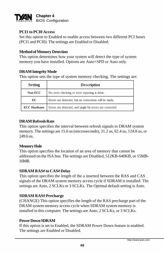
PCI1 to PCI0 AccessSet this option to Enabled to enable access between two different PCI buses(PCI1 and PCI0). The settings are Enabled or Disabled.
Method of Memory DetectionThis option determines how your system will detect the type of systemmemory you have installed. Options are Auto+SPD or Auto only.
DRAM Integrity ModeThis option sets the type of system memory checking. The settings are:
DRAM Refresh RateThis option specifies the interval between refresh signals to DRAM systemmemory. The settings are 15.6 us (microseconds), 31.2 us, 62.4 us, 124.8 us, or249.6 us.
Memory HoleThis option specifies the location of an area of memory that cannot beaddressed on the ISA bus. The settings are Disabled, 512KB-640KB, or 15MB-16MB.
SDRAM RAS# to CAS# DelayThis option specifies the length of the a inserted between the RAS and CASsignals of the DRAM system memory access cycle if SDRAM is installed. Thesettings are Auto, 2 SCLKs or 3 SCLKs. The Optimal default setting is Auto.
SDRAM RAS# Precharge(CHANGE) This option specifies the length of the RAS precharge part of theDRAM system memory access cycle when SDRAM system memory isinstalled in this computer. The settings are Auto, 2 SCLKs, or 3 SCLKs.
Power Down SDRAMIf this option is set to Enabled, the SDRAM Power Down feature is enabled.The settings are Enabled or Disabled.
gnitteS noitpircseD
CCEnoN .enodsignitroperrorrerognikcehcrorreoN
CE .edameblliwsnoitcerrocontub,detcetederasrorrE
erawdraHCCE .detcerrocerasrorretibelgnisdna,detcetederasrorrE
S1830 Tsunami AT
49
BIO
S
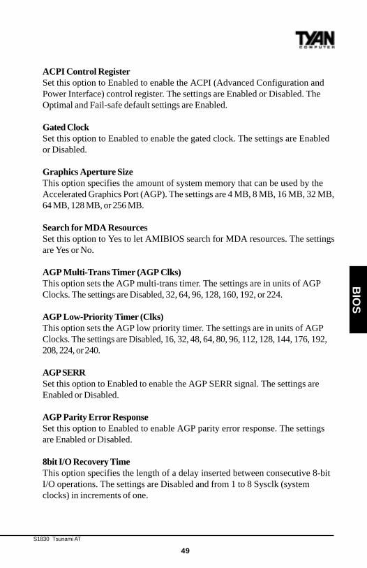
ACPI Control RegisterSet this option to Enabled to enable the ACPI (Advanced Configuration andPower Interface) control register. The settings are Enabled or Disabled. TheOptimal and Fail-safe default settings are Enabled.
Gated ClockSet this option to Enabled to enable the gated clock. The settings are Enabledor Disabled.
Graphics Aperture SizeThis option specifies the amount of system memory that can be used by theAccelerated Graphics Port (AGP). The settings are 4 MB, 8 MB, 16 MB, 32 MB,64 MB, 128 MB, or 256 MB.
Search for MDA ResourcesSet this option to Yes to let AMIBIOS search for MDA resources. The settingsare Yes or No.
AGP Multi-Trans Timer (AGP Clks)This option sets the AGP multi-trans timer. The settings are in units of AGPClocks. The settings are Disabled, 32, 64, 96, 128, 160, 192, or 224.
AGP Low-Priority Timer (Clks)This option sets the AGP low priority timer. The settings are in units of AGPClocks. The settings are Disabled, 16, 32, 48, 64, 80, 96, 112, 128, 144, 176, 192,208, 224, or 240.
AGP SERRSet this option to Enabled to enable the AGP SERR signal. The settings areEnabled or Disabled.
AGP Parity Error ResponseSet this option to Enabled to enable AGP parity error response. The settingsare Enabled or Disabled.
8bit I/O Recovery TimeThis option specifies the length of a delay inserted between consecutive 8-bitI/O operations. The settings are Disabled and from 1 to 8 Sysclk (systemclocks) in increments of one.
http://www.tyan.com
50
Chapter 4BIOS Configuration
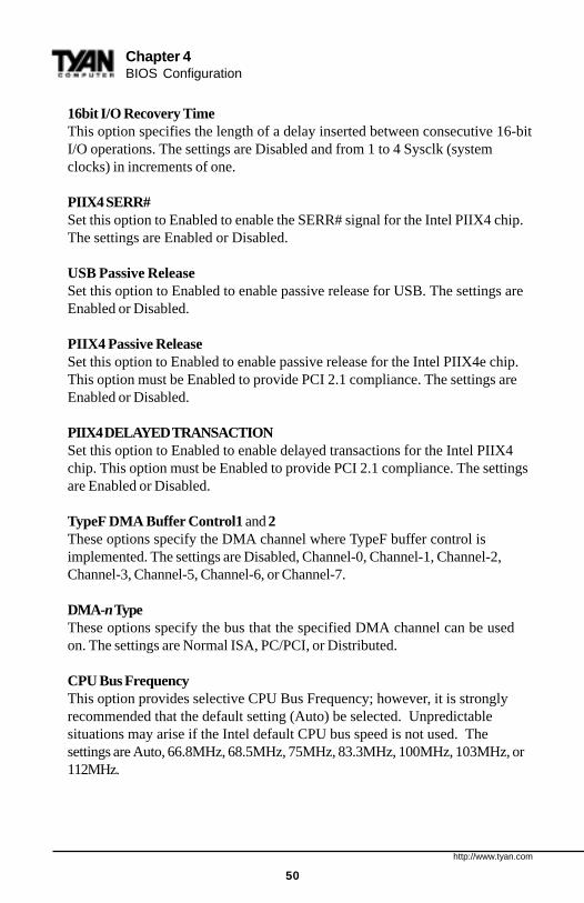
16bit I/O Recovery TimeThis option specifies the length of a delay inserted between consecutive 16-bitI/O operations. The settings are Disabled and from 1 to 4 Sysclk (systemclocks) in increments of one.
PIIX4 SERR#Set this option to Enabled to enable the SERR# signal for the Intel PIIX4 chip.The settings are Enabled or Disabled.
USB Passive ReleaseSet this option to Enabled to enable passive release for USB. The settings areEnabled or Disabled.
PIIX4 Passive ReleaseSet this option to Enabled to enable passive release for the Intel PIIX4e chip.This option must be Enabled to provide PCI 2.1 compliance. The settings areEnabled or Disabled.
PIIX4 DELAYED TRANSACTIONSet this option to Enabled to enable delayed transactions for the Intel PIIX4chip. This option must be Enabled to provide PCI 2.1 compliance. The settingsare Enabled or Disabled.
TypeF DMA Buffer Control1 and 2These options specify the DMA channel where TypeF buffer control isimplemented. The settings are Disabled, Channel-0, Channel-1, Channel-2,Channel-3, Channel-5, Channel-6, or Channel-7.
DMA-n TypeThese options specify the bus that the specified DMA channel can be usedon. The settings are Normal ISA, PC/PCI, or Distributed.
CPU Bus FrequencyThis option provides selective CPU Bus Frequency; however, it is stronglyrecommended that the default setting (Auto) be selected. Unpredictablesituations may arise if the Intel default CPU bus speed is not used. Thesettings are Auto, 66.8MHz, 68.5MHz, 75MHz, 83.3MHz, 100MHz, 103MHz, or112MHz.
S1830 Tsunami AT
51
BIO
S
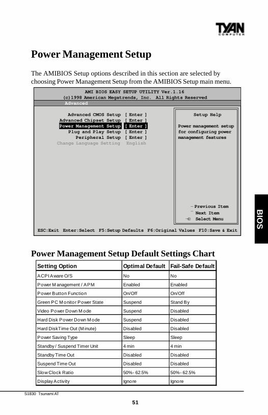
Power Management Setup
The AMIBIOS Setup options described in this section are selected bychoosing Power Management Setup from the AMIBIOS Setup main menu.
Power Management Setup Default Settings Chart
®¬
AMI BIOS EASY SETUP UTILITY Ver.1.16 (c)1998 American Megatrends, Inc. All Rights Reserved Advanced
Advanced CMOS Setup [ Enter ] Setup Help Advanced Chipset Setup [ Enter ] Power Management Setup [ Enter ] Power management setup Plug and Play Setup [ Enter ] for configuring power Peripheral Setup [ Enter ] management features Change Language Setting English
- Previous Item
¯ Next ItemSelect Menu
ESC:Exit Enter:Select F5:Setup Defaults F6:Original Values F10:Save & Exit
Setting Option Optimal Default Fail-Safe Default
ACP I Aware O/S No No
P ower Management / AP M Enabled Enabled
P ower B utton F unction On/Off On/Off
Green P C Monitor P ower S tate S us pend S tand B y
Video P ower Down Mode S us pend Dis abled
Hard Dis k P ower Down Mode S us pend Dis abled
Hard Dis kT ime Out (Minute) Dis abled Dis abled
P ower S aving T ype S leep S leep
S tandby / S us pend T imer Unit 4 min 4 min
S tandby T ime Out Dis abled Dis abled
S us pend T ime Out Dis abled Dis abled
S low Clock R atio 50% - 62.5% 50% - 62.5%
Dis play Activity Ignore Ignore
http://www.tyan.com
52
Chapter 4BIOS Configuration
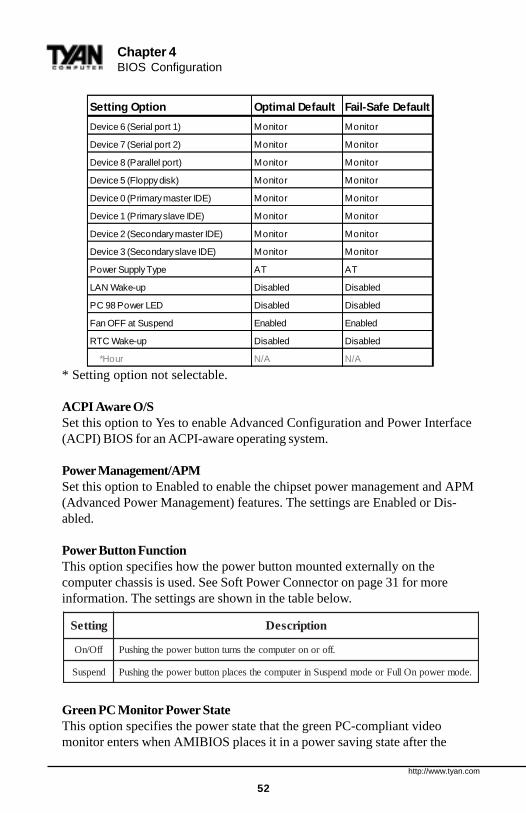
* Setting option not selectable.
ACPI Aware O/SSet this option to Yes to enable Advanced Configuration and Power Interface(ACPI) BIOS for an ACPI-aware operating system.
Power Management/APMSet this option to Enabled to enable the chipset power management and APM(Advanced Power Management) features. The settings are Enabled or Dis-abled.
Power Button FunctionThis option specifies how the power button mounted externally on thecomputer chassis is used. See Soft Power Connector on page 31 for moreinformation. The settings are shown in the table below.
Green PC Monitor Power StateThis option specifies the power state that the green PC-compliant videomonitor enters when AMIBIOS places it in a power saving state after the
gnitteS noitpircseD
ffO/nO .fforonoretupmocehtsnrutnottubrewopehtgnihsuP
dnepsuS .edomrewopnOlluFroedomdnepsuSniretupmocehtsecalpnottubrewopehtgnihsuP
Setting Option Optimal Default Fail-Safe Default
Device 6 (Serial port 1) Monitor Monitor
Device 7 (Serial port 2) Monitor Monitor
Device 8 (Parallel port) Monitor Monitor
Device 5 (F loppy dis k) Monitor Monitor
Device 0 (P rimary master IDE) Monitor Monitor
Device 1 (P rimary s lave IDE) Monitor Monitor
Device 2 (Secondary mas ter IDE) Monitor Monitor
Device 3 (Secondary s lave IDE) Monitor Monitor
Power Supply T ype AT AT
LAN Wake-up Disabled Disabled
PC 98 Power LED Disabled Disabled
F an OF F at Sus pend Enabled Enabled
RT C Wake-up Disabled Disabled
*Hour N/A N/A
S1830 Tsunami AT
53
BIO
S
specified period of display inactivity has expired. The settings are Off, StandBy, or Suspend.
Video Power Down ModeThis option specifies the power state that the video subsystem enters whenAMIBIOS places it in a power saving state after the specified period of displayinactivity has expired. The settings are Stand By, Suspend, or Disabled.
Hard Disk Power Down ModeThis option specifies the power conserving state that the hard disk driveenters after the specified period of hard drive inactivity has expired. Thesettings are Disabled, Stand By, or Suspend.
Hard Disk Time Out (Minute)This option specifies the length of a period of hard disk drive inactivity. Whenthis length of time expires, the computer enters power-conserving statespecified in the Hard Disk Power Down Mode option (see above). The settingsare Disabled, and from 1 to 15 minutes, in one minute intervals.
Power Saving TypeThere are several types of sleeping states within the general sleep state. Thisoption allows you to choose how “asleep” you want your system to be. Indeeper sleep modes, more energy is saved. However, upon waking up, thesystem must “reorient” itself, and reestablish control over the system’ssleeping components. The settings are POS, Sleep, Stop Clock, and DeepSleep. POS is the lightest sleep mode; Deep Sleep is the heaviest.
Standby/Suspend Timer UnitThis option specifies the unit of time used for the Standby and Suspend timeout periods. The settings are 4 msec, 4 sec, 32 sec, or 4 min.
Standby Time OutThis option defines the length of time that the system, while in Full On state,must be inactive before it enters Standby mode. The settings are Disabled andfrom 4 minutes to 508 minutes, in increments of 4 minutes.
Suspend Time OutThis option defines the length of time that the system, while in Standby mode,must be inactive before it enters Suspend mode. The settings are Disabled andfrom 4 minutes to 508 minutes, in increments of 4 minutes.
http://www.tyan.com
54
Chapter 4BIOS Configuration
Slow Clock RatioThis option specifies the speed at which the system clock runs in the StandbyMode power saving state. The settings are expressed as a percentage of thenormal CPU clock speed. The settings are 0-12.5%, 12.5%-25%, 25%-37.5%,37.5%-50%, 50%-62.5%, 62.5%-75%, or 75-87.5%.
Display ActivityWhen set to Monitor, this option enables event monitoring on the videodisplay. If set to Monitor and the computer is in a power saving state, displayactivity will cause the system to enter the Full On state. AMIBIOS reloads theStandby and Suspend time-out timers if display activity occurs. The settingsare Monitor or Ignore.
Device n (Device identity)When set to Monitor, these options enable event monitoring on the specifiedhardware interrupt request line. If set to Monitor and the computer is in apower saving state, any activity on the IRQ line will cause the system to enterthe Full On state. AMIBIOS reloads the Standby and Suspend time-out timersif activity occurs on the specified IRQ line. The settings for each of theseoptions are Monitor or Ignore.
LAN Wake-upWhen this option is Enabled, the system will wake up when a signal isreceived on the Wake-on LAN header. In order for this wake up function towork, the system must have been brought up at least past the POST before itwas last shut down (i.e. if you turn the system off before the POST, theregistry will not be set, and the system will not be able to wake up using thisfunction). This function requires an ATX 2.01 compliant power supply with 5Vstandby (STB5V) current of at least 800mA. The settings are Enabled orDisabled.
PC98 Power LEDWhen this option is Enabled, your power LED will turn to yellow when yoursystem is in Suspend mode. Note that if you do not have a two-color LED,your LED will turn off when the system is in Suspend mode if this option is setto Enabled. The settings are Enabled or Disabled.
FAN OFF at SuspendIf this option is Enabled, the CPU fan will turn off when the system is inSuspend mode. If Disabled, the CPU fan will remain on while the system is inSuspend mode. The settings are Enabled or Disabled.
S1830 Tsunami AT
55
BIO
S
RTC Wake-upIf Enabled, this option allows you to set an hour and minute for the system towake up. The next two fields allow you to choose the wake up time. Note thatthe time fields will not be available if this option is set to Disabled. In order forthis wake up function to work, the system must have been brought up at leastpast the POST before it was last shut down (i.e. if you turn the system offbefore the POST, the registry will not be set, and the system will not be able towake up using this function). The settings are Enabled or Disabled.
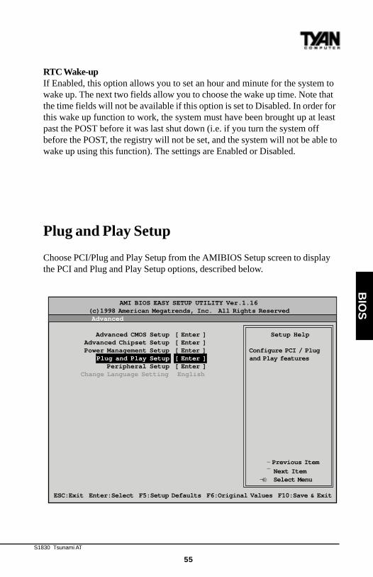
Plug and Play Setup
Choose PCI/Plug and Play Setup from the AMIBIOS Setup screen to displaythe PCI and Plug and Play Setup options, described below.
®¬
AMI BIOS EASY SETUP UTILITY Ver.1.16 (c)1998 American Megatrends, Inc. All Rights Reserved Advanced
Advanced CMOS Setup [ Enter ] Setup Help Advanced Chipset Setup [ Enter ] Power Management Setup [ Enter ] Configure PCI / Plug Plug and Play Setup [ Enter ] and Play features Peripheral Setup [ Enter ] Change Language Setting English
- Previous Item
¯ Next ItemSelect Menu
ESC:Exit Enter:Select F5:Setup Defaults F6:Original Values F10:Save & Exit

http://www.tyan.com
56
Chapter 4BIOS Configuration
Plug and Play Setup Default Settings Chart
* Setting option is not selectable
Setting Option Optimal Default Fail-Safe Default
P lug and P lay Aware O/S Yes Yes
P CI Latency T imer (P CI Clocks ) 64 64
P CI VGA P alette S noop Dis abled Dis abled
Allocate IR Q to P CI VGA Yes Yes
P CI IDE B us Mas ter Dis abled Dis abled
OffB oard P CI IDE Card Auto Auto
*OffB oard P CI IDE P rimary IR Q Dis abled Dis abled
*OffB oard P CI IDE S econdary IR Q Dis abled Dis abled
P CI S lot1 IR Q P riority Auto Auto
P CI S lot2 IR Q P riority Auto Auto
P CI S lot3 IR Q P riority Auto Auto
P CI S lot4 IR Q P riority Auto Auto
DMA Channel 0 P nP P nP
DMA Channel 1 P nP P nP
DMA Channel 3 P nP P nP
DMA Channel 5 P nP P nP
DMA Channel 6 P nP P nP
DMA Channel 7 P nP P nP
IR Q3 P CI/P nP P CI/P nP
IR Q4 P CI/P nP P CI/P nP
IR Q5 P CI/P nP P CI/P nP
IR Q7 P CI/P nP P CI/P nP
IR Q9 P CI/P nP P CI/P nP
IR Q10 P CI/P nP P CI/P nP
IR Q11 P CI/P nP P CI/P nP
IR Q12 P CI/P nP P CI/P nP
IR Q14 P CI/P nP P CI/P nP
IR Q15 P CI/P nP P CI/P nP
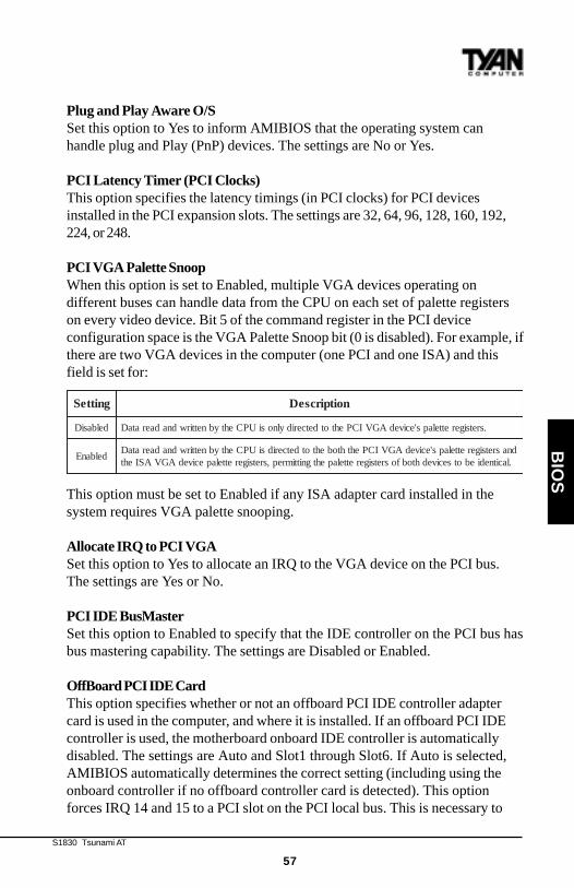
S1830 Tsunami AT
57
BIO
S
Plug and Play Aware O/SSet this option to Yes to inform AMIBIOS that the operating system canhandle plug and Play (PnP) devices. The settings are No or Yes.
PCI Latency Timer (PCI Clocks)This option specifies the latency timings (in PCI clocks) for PCI devicesinstalled in the PCI expansion slots. The settings are 32, 64, 96, 128, 160, 192,224, or 248.
PCI VGA Palette SnoopWhen this option is set to Enabled, multiple VGA devices operating ondifferent buses can handle data from the CPU on each set of palette registerson every video device. Bit 5 of the command register in the PCI deviceconfiguration space is the VGA Palette Snoop bit (0 is disabled). For example, ifthere are two VGA devices in the computer (one PCI and one ISA) and thisfield is set for:
This option must be set to Enabled if any ISA adapter card installed in thesystem requires VGA palette snooping.
Allocate IRQ to PCI VGASet this option to Yes to allocate an IRQ to the VGA device on the PCI bus.The settings are Yes or No.
PCI IDE BusMasterSet this option to Enabled to specify that the IDE controller on the PCI bus hasbus mastering capability. The settings are Disabled or Enabled.
OffBoard PCI IDE CardThis option specifies whether or not an offboard PCI IDE controller adaptercard is used in the computer, and where it is installed. If an offboard PCI IDEcontroller is used, the motherboard onboard IDE controller is automaticallydisabled. The settings are Auto and Slot1 through Slot6. If Auto is selected,AMIBIOS automatically determines the correct setting (including using theonboard controller if no offboard controller card is detected). This optionforces IRQ 14 and 15 to a PCI slot on the PCI local bus. This is necessary to
gnitteS noitpircseD
delbasiD .sretsigerettelaps'ecivedAGVICPehtotdetceridylnosiUPCehtybnettirwdnadaerataD
delbanEdnasretsigerettelaps'ecivedAGVICPehthtobehtotdetceridsiUPCehtybnettirwdnadaerataD.lacitnediebotsecivedhtobfosretsigerettelapehtgnittimrep,sretsigerettelapecivedAGVASIeht
http://www.tyan.com
58
Chapter 4BIOS Configuration
support non-compliant PCI IDE adapter cards.
OffBoard PCI IDE Primary IRQThis option specifies the PCI interrupt used by the primary IDE channel on theoffboard PCI IDE controller. The settings are Disabled, Hardwired, INTA,INTB, INTC, or INTD.
Offboard PCI IDE Secondary IRQThis option specifies the PCI interrupt used by the secondary IDE channel onthe offboard PCI IDE controller. The settings are Disabled, Hardwired, INTA,INTB, INTC, or INTD.
PCI Slot n IRQ PriorityThese options specify the IRQ priority for PCI devices installed in the PCIdevices installed in the PCI expansion slots. The settings are Auto, IRQ 3, 4, 5,7, 9, 10, and 11, in priority order.
DMA Channel nThese options allow you to specify the bus type used by each DMA channel.The settings are PnP or ISA/EISA .
IRQnThese options specify the bus that the specified IRQ line is used on. Theseoptions allow you to reserve IRQs for legacy ISA adapter cards. Theseoptions determine if AMIBIOS should remove an IRQ from the pool ofavailable IRQs passed to devices that are configurable by the system BIOS.The available IRQ pool is determined by reading the ESCD NVRAM. If moreIRQs must be removed from the pool, you can use these options to reserve theIRQ by assigning an ISA/EISA setting to it. Onboard I/O is configured byAMIBIOS. All IRQs used by onboard I/O are configured as PCI/PnP. IRQ12only appears if the Mouse Support option in Advanced Setup is set toDisabled. IRQ14 and 15 will not be available if the onboard PCI IDE is enabled.If all IRQs are set to ISA/EISA and IRQ14 and 15 are allocated to the onboardPCI IDE, IRQ9 will still be available for PCI and PnP devices, because at leastone IRQ must be available for PCI and PnP devices. The settings are ISA/EISAor PCI/PnP.
Reserved Memory Size This option specifies the size of the memory area reserved for legacy ISAadapter cards. The settings are Disabled, 16K, 32K, or 64K.
S1830 Tsunami AT
59
BIO
S
Reserved Memory AddressThis option specifies the beginning address (in hex) of the reserved memoryarea. The specified ROM memory area is reserved for use by legacy ISAadapter cards. This option does not appear if the Reserved Memory Sizeoption is set to Disabled. The settings are C0000, C4000, C8000, CC000, D0000,D4000, D8000, or DC000.
PCI Device Search OrderThis option changes the BIOS scan order of the PCI slot - from first to last orlast to first. The settings are First-Last or Last-First.
BIOS Devnode for Shadow RAMThis option is used for some add-on card ROMs which do not claim the correctmemory range that they occupy. The settings are Disabled or Enabled.
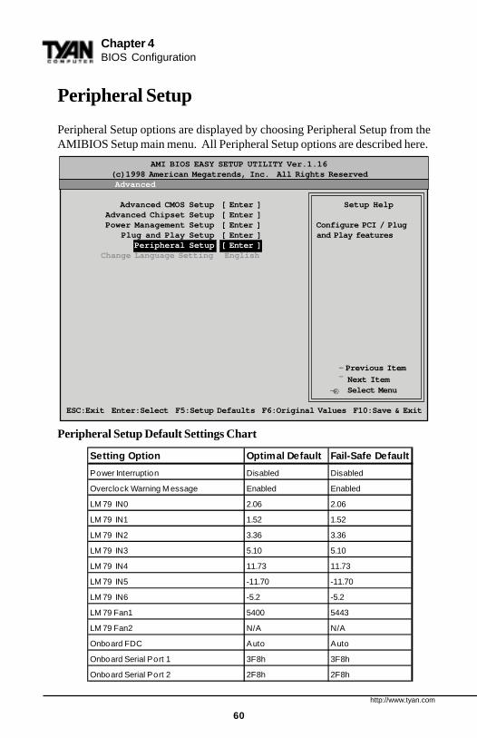
http://www.tyan.com
60
Chapter 4BIOS Configuration
Peripheral Setup
Peripheral Setup options are displayed by choosing Peripheral Setup from theAMIBIOS Setup main menu. All Peripheral Setup options are described here.
Peripheral Setup Default Settings Chart
®¬
AMI BIOS EASY SETUP UTILITY Ver.1.16 (c)1998 American Megatrends, Inc. All Rights Reserved Advanced
Advanced CMOS Setup [ Enter ] Setup Help Advanced Chipset Setup [ Enter ] Power Management Setup [ Enter ] Configure PCI / Plug Plug and Play Setup [ Enter ] and Play features Peripheral Setup [ Enter ] Change Language Setting English
- Previous Item
¯ Next ItemSelect Menu
ESC:Exit Enter:Select F5:Setup Defaults F6:Original Values F10:Save & Exit
Setting Option Optimal Default Fail-Safe Default
P ower Interruption Dis abled Dis abled
Overclock Warning Mes s age Enabled Enabled
LM79 IN0 2.06 2.06
LM79 IN1 1.52 1.52
LM79 IN2 3.36 3.36
LM79 IN3 5.10 5.10
LM79 IN4 11.73 11.73
LM79 IN5 -11.70 -11.70
LM79 IN6 -5.2 -5.2
LM79 F an1 5400 5443
LM79 F an2 N/A N/A
Onboard F DC Auto Auto
Onboard S erial P ort 1 3F 8h 3F 8h
Onboard S erial P ort 2 2F 8h 2F 8h
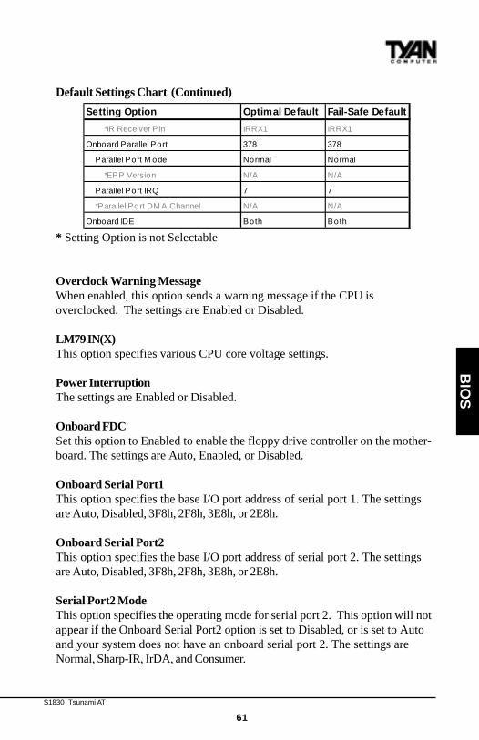
S1830 Tsunami AT
61
BIO
S
Default Settings Chart (Continued)
* Setting Option is not Selectable
Overclock Warning MessageWhen enabled, this option sends a warning message if the CPU isoverclocked. The settings are Enabled or Disabled.
LM79 IN(X)This option specifies various CPU core voltage settings.
Power InterruptionThe settings are Enabled or Disabled.
Onboard FDC Set this option to Enabled to enable the floppy drive controller on the mother-board. The settings are Auto, Enabled, or Disabled.
Onboard Serial Port1 This option specifies the base I/O port address of serial port 1. The settingsare Auto, Disabled, 3F8h, 2F8h, 3E8h, or 2E8h.
Onboard Serial Port2 This option specifies the base I/O port address of serial port 2. The settingsare Auto, Disabled, 3F8h, 2F8h, 3E8h, or 2E8h.
Serial Port2 ModeThis option specifies the operating mode for serial port 2. This option will notappear if the Onboard Serial Port2 option is set to Disabled, or is set to Autoand your system does not have an onboard serial port 2. The settings areNormal, Sharp-IR, IrDA, and Consumer.
Setting Option Optimal Default Fail-Safe Default
*IR R eceiver P in IR R X1 IR R X1
Onboard P arallel P ort 378 378
P arallel P ort Mode Normal Normal
*EP P Vers ion N/A N/A
P arallel P ort IR Q 7 7
*P arallel P ort DMA Channel N/A N/A
Onboard IDE B oth B oth
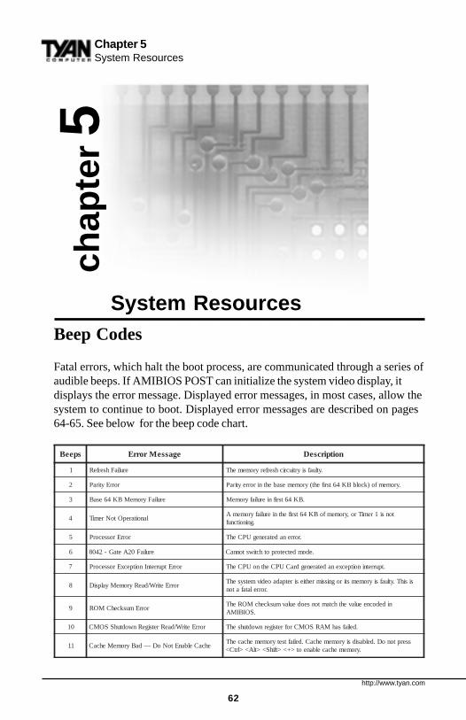
http://www.tyan.com
62
Chapter 5System Resources
chap
ter 5
System ResourcesBeep Codes
Fatal errors, which halt the boot process, are communicated through a series ofaudible beeps. If AMIBIOS POST can initialize the system video display, itdisplays the error message. Displayed error messages, in most cases, allow thesystem to continue to boot. Displayed error messages are described on pages64-65. See below for the beep code chart.
speeB egasseMrorrE noitpircseD
1 eruliaFhserfeR .ytluafsiyrtiucrichserferyromemehT
2 rorrEytiraP .yromemfo)kcolbBK46tsrifeht(yromemesabehtnirorreytiraP
3 eruliaFyromeMBK46esaB .BK46tsrifnieruliafyromeM
4 lanoitarepOtoNremiTtonsi1remiTro,yromemfoBK46tsrifehtnieruliafyromemA
.gninoitcnuf
5 rorrErossecorP .rorrenadetarenegUPCehT
6 eruliaF02AetaG-2408 .edomdetcetorpothctiwstonnaC
7 rorrEtpurretnInoitpecxErossecorP .tpurretninoitpecxenadetarenegdraCUPCehtnoUPCehT
8 rorrEetirW/daeRyromeMyalpsiDsisihT.ytluafsiyromemstirognissimrehtiesiretpadaoedivmetsysehT
.rorrelatafaton
9 rorrEmuskcehCMORnidedocneeulavehthctamtonseodeulavmuskcehcMORehT
.SOIBIMA
01 rorrEetirW/daeRretsigeRnwodtuhSSOMC .deliafsahMARSOMCrofretsigernwodtuhsehT
11 ehcaCelbanEtoNoD—daByromeMehcaCsserptonoD.delbasidsiyromemehcaC.deliaftsetyromemehcacehT
.yromemehcacelbaneot>+<>tfihS<>tlA<>lrtC<
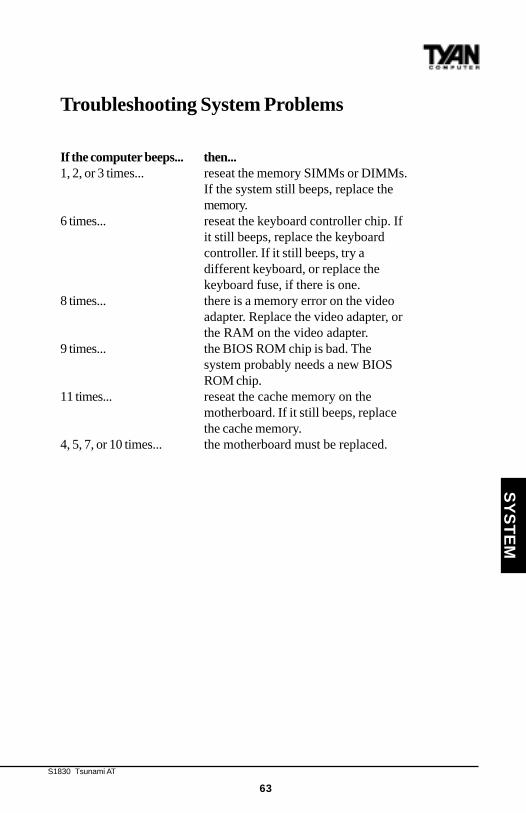
S1830 Tsunami AT
63
SY
ST
EM
Troubleshooting System Problems
If the computer beeps... then...1, 2, or 3 times... reseat the memory SIMMs or DIMMs.
If the system still beeps, replace thememory.
6 times... reseat the keyboard controller chip. Ifit still beeps, replace the keyboardcontroller. If it still beeps, try adifferent keyboard, or replace thekeyboard fuse, if there is one.
8 times... there is a memory error on the videoadapter. Replace the video adapter, orthe RAM on the video adapter.
9 times... the BIOS ROM chip is bad. Thesystem probably needs a new BIOSROM chip.
11 times... reseat the cache memory on themotherboard. If it still beeps, replacethe cache memory.
4, 5, 7, or 10 times... the motherboard must be replaced.

http://www.tyan.com
64
egasseMrorrE noitanalpxE
rorrE02A-etaG2408 .2408ehtecalpeR.gnikrowtonsi)2408(rellortnocdraobyekehtno02AetaG
!trohSeniLsserddA .yrtiucricgnidocedsserddaehtnirorrE
rorrEevirD:Cdrah:CehtkcehC.ytilitUksiDdraHgaiDIMAehtnuR.:CevirdmorfesnopseroN
.puteSdradnatSniepytksid
eruliaFevirD:C .evirdehtecalpeR.:CevirdksiddrahmorfesnopseroN
,daByromeMehcaC!ehcaCelbanEtoNoD
.gaiDIMAnuR.evitcefedsiyromemehcaC
rorrEremiT2-HC .2remitnirorrenasierehT.sremitowtsahmetsysTAnA
etatSyrettaBSOMCwoL
ehtecalpeR.wolsirewopyrettabehT.yrettabaybderewopsiMARSOMC.yrettab
muskcehCSOMCeruliaF
.puteSSOIBNIWnuR.eulavsuoiverpehtnahttnereffidsimuskcehcMARSOMC
metsySSOMCteStoNsnoitpO
.puteSSOIBNIWnuR.deyortsedneebevahMARSOMCniderotsseulavehT
epyTyalpsiDSOMChctamsiM
SOIBNIWnuR.detcetedepytehthctamtonseodMARSOMCniepytoedivehT.puteS
eziSyromeMSOMChctamsiM
SOMCnitnuomaehtnahttnereffidsiSOIBIMAybdnuofyromemfotnuomaehT.puteSSOIBNIWnuR.MAR
etaDdnaemiTSOMCteStoN
.emitdnaetadehttesotputeSdradnatSnuR
rorrEevirD:DdrahehtkcehC.ytilitUksiDdraHgaiDIMAehtnuR.:DevirdmorfesnopseroN
.puteSdradnatSniepytksid
Displayed Error Messages
If an error occurs after the system display has been initialized, the errormessage will be displayed as follows:
ERROR Message Line 1ERROR Message Line 2Press <F1> to continue
and the system will halt. The system will not halt if the Wait for <F1> If AnyError option in Advanced Setup is Disabled.
RUN SETUP UTILITY
may also appear. Press <F1> to run WINBIOS Setup if this message appears.
Chapter 5System Resources
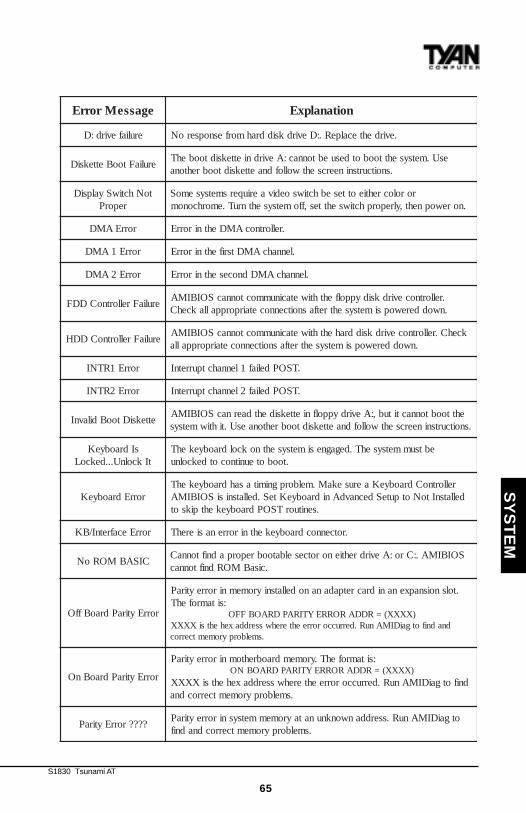
S1830 Tsunami AT
65
egasseMrorrE noitanalpxE
eruliafevird:D .evirdehtecalpeR.:DevirdksiddrahmorfesnopseroN
eruliaFtooBetteksiDesU.metsysehttoobotdesuebtonnac:AevirdnietteksidtoobehT
.snoitcurtsnineercsehtwollofdnaetteksidtoobrehtona
toNhctiwSyalpsiDreporP
rorolocrehtieottesebhctiwsoedivaeriuqersmetsysemoS.norewopneht,ylreporphctiwsehttes,ffometsysehtnruT.emorhconom
rorrEAMD .rellortnocAMDehtnirorrE
rorrE1AMD .lennahcAMDtsrifehtnirorrE
rorrE2AMD .lennahcAMDdnocesehtnirorrE
eruliaFrellortnoCDDF.rellortnocevirdksidyppolfehthtiwetacinummoctonnacSOIBIMA.nwodderewopsimetsysehtretfasnoitcennocetairporppallakcehC
eruliaFrellortnoCDDHkcehC.rellortnocevirdksiddrahehthtiwetacinummoctonnacSOIBIMA
.nwodderewopsimetsysehtretfasnoitcennocetairporppalla
rorrE1RTNI .TSOPdeliaf1lennahctpurretnI
rorrE2RTNI .TSOPdeliaf2lennahctpurretnI
etteksiDtooBdilavnIehttoobtonnactitub,:AevirdyppolfnietteksidehtdaernacSOIBIMA
.snoitcurtsnineercsehtwollofdnaetteksidtoobrehtonaesU.tihtiwmetsys
sIdraobyeKtIkcolnU...dekcoL
ebtsummetsysehT.degagnesimetsysehtnokcoldraobyekehT.tooboteunitnocotdekcolnu
rorrEdraobyeKrellortnoCdraobyeKaerusekaM.melborpgnimitasahdraobyekehT
dellatsnItoNotputeSdecnavdAnidraobyeKteS.dellatsnisiSOIBIMA.senituorTSOPdraobyekehtpiksot
rorrEecafretnI/BK .rotcennocdraobyekehtnirorrenasierehT
CISABMORoNSOIBIMA.:Cro:AevirdrehtienorotceselbatoobreporpadniftonnaC
.cisaBMORdniftonnac
rorrEytiraPdraoBffO
.tolsnoisnapxenanidracretpadananodellatsniyromemnirorreytiraP:sitamrofehT
)XXXX(=RDDARORREYTIRAPDRAOBFFOdnadnifotgaiDIMAnuR.derruccororreehterehwsserddaxehehtsiXXXX
.smelborpyromemtcerroc
rorrEytiraPdraoBnO
:sitamrofehT.yromemdraobrehtomnirorreytiraP)XXXX(=RDDARORREYTIRAPDRAOBNO
dnifotgaiDIMAnuR.derruccororreehterehwsserddaxehehtsiXXXX.smelborpyromemtcerrocdna
????rorrEytiraPotgaiDIMAnuR.sserddanwonknunatayromemmetsysnirorreytiraP
.smelborpyromemtcerrocdnadnif
SY
ST
EM
http://www.tyan.com
66
Chapter 5System Resources
Glossary
ACPI (Advanced Configuration and Power Interface) is a power manage-ment specification that allows the operating system to control the amount ofpower distributed to the computer’s devices. Devices not in use can be turnedoff, reducing unnecessary power expenditure.
AGP (Accelerated Graphics Port) is a PCI-based interface which wasdesigned specifically for demands of 3D graphics applications. The 32-bitAGP channel directly links the graphics controller to the main memory.While the channel runs at only 66MHz, it supports data transmission duringboth the rising and falling ends of the clock cycle, yielding an effective speedof 133MHz.
The AT was the original form factor of IBM’s PC.
ATAPI (AT A ttachment Packet Interface), also known as IDE or ATA, is adrive implementation that includes the disk controller on the device itself. Itallows CD-ROMs and tape drives to be configured as master or slave devices,just like hard drives.
The ATX form factor was designed to replace the AT form factor. It improveson the AT design by rotating the board ninety degrees, so that the IDEconnectors are closer to the drive bays, and the CPU is closer to the powersupply and cooling fan. The keyboard, mouse, serial, USB, and parallel portsare built in.
Bandwidth refers to carrying capacity. The greater the bandwidth, themore data the bus, phone line, or other electrical path, can carry. Greaterbandwidth, then, also results in greater speed.
A BBS (Bulletin Board System) is a computer system with a number ofmodems hooked up to it which acts as a center for users to post messages andaccess information.
The BIOS (Basic Input/Output System) program resides in the ROM chip,and provides the basic instructions for controlling your computer’s hardware.Both the operating system and application software use BIOS routines toensure compatibility.
S1830 Tsunami AT
67
A buffer is a portion of RAM which is used to temporarily store data, usuallyfrom an application, though it is also used when printing, and in most key-board drivers. The CPU can manipulate data in a buffer before copying it, all atonce, to a disk drive. While this improves system performance--reading to orwriting from a disk drive a single time is much faster than doing so repeatedly--there is the possibility of losing your data should the system crash. Informa-tion stored in a buffer is temporarily stored, not permanently saved.
A bus is a data pathway. The term is used especially to refer to the connec-tion between the processor and system memory, and between the processorand PCI or ISA local buses.
Bus mastering allows peripheral devices and IDEs to access the systemmemory without going through the CPU (similar to DMA channels).
A cache is a temporary storage area for data that will be needed often by anapplication. Using a cache lowers data access times, since the neededinformation is stored in the SRAM instead of in the slower DRAM. Note thatthe cache is also much smaller than your regular memory: a typical cachesize is 512KB, while you may have as much as 1GB of regular memory.
Cache size refers to the physical size of the cache onboard. This should notbe confused with the cacheable area, which is the total amount of memorywhich can be scanned by the system in search of data to put into the cache. Atypical setup would be a cache size of 512KB, and a cacheable area of512MB. In this case, up to 512MB of the main memory onboard is capable ofbeing cached. However, only 512KB of this memory will be in the cache atany given moment. Any main memory above 512MB could never be cached.
Closed and open jumpers Jumpers and jumper pins are active whenthey are On or Closed, and inactive when they are Off or Open.
CMOS Complementary Metal-Oxide Semiconductors are chips that holdthe basic start-up information for the BIOS.
The COM port is another name for the serial port, which is so-calledbecause it transmits the eight bits of a byte of data along one wire, andreceives data on another single wire (that is, the data is transmitted in serialform, one bit after another). Parallel ports transmit the bits of a byte on eight
SY
ST
EM
http://www.tyan.com
68
different wires at the same time (that is, in parallel form, eight bits at the sametime).
DIMM Dual In-line Memory Modules are a faster and more capaciousform of RAM than SIMMs, and do not need to be installed in pairs.
DIMM bank DIMM banks are sometimes called DIMM sockets, becausethe physical slot and the logical unit are the same. That is, one DIMMmodule fits into one DIMM socket, which is capable of acting as a memorybank.
DMA Direct Memory Access channels are similar to IRQs. DMA channelsallow hardware devices (like sound cards or keyboards) to access the mainmemory without involving the CPU. This frees up CPU resources for othertasks. As with IRQs, it is vital that you do not double up devices on a singleline. Plug and Play devices will take care of this for you.
In Doze mode, only the CPU’s speed is slowed.
DRAM Dynamic RAM is a widely available, very affordable form of RAMwhich has the unfortunate tendency to lose data if it is not recharged regu-larly (every few milliseconds). This refresh requirement makes DRAMslower three to ten times slower than non-recharged RAM such as SRAM.
EDO RAM (Extended Data-Out RAM ) speeds access to memory loca-tions by assuming that memory addresses are static: the next time it looks fora bit of data, it will be at the same spot, or one nearby.
EEPROM Electrically Erasable Programmable ROM, also called FlashBIOS, is a ROM chip which can, unlike normal ROM, be updated. Thisallows you to keep up with changes in the BIOS programs without having tobuy a new chip. TYAN’s BIOS updates can be found at http://www.tyan.com/html/drivers.html
ESCD (Extended System Configuration Data) is a format for storing informa-tion about Plug and Play devices in the system BIOS. This information helpsproperly configure the system each time it boots.
Firmware is low level software that controls the system hardware.
Chapter 5System Resources
S1830 Tsunami AT
69
Form factor is an industry term for the size, shape, power supply type, andexternal connector type of the PCB (personal computer board) or motherboard.The standard form factors are the AT and ATX, although TYAN also makessome Baby-AT boards.
A Global timer is an onboard hardware timer, such as the Real TimeClock.
Handshaking is a form of encryption. One system, typically the server,sends an encryption scheme to another agent, typically a client. Thus, theclient’s data is protected during transmittal to the server.
HDD stands for Hard Disk Drive.
H-SYNC controls the horizontal properties of the monitor.
IC (Integrated Circuit) is the formal name for the computer chip.
IDE Integrated Device (or Drive) Electronics is a simple, self-containedhard drive interface. It can handle drives up to 8.4GB in size. Almost allIDEs sold now are in fact Enhanced IDEs (EIDEs).
IDE INT (IDE Int errupt) is a hardware interrupt signal that goes to theIDE.
I/O Input/Output is the connection between your computer and anotherpiece of hardware (mouse, keyboard, etc.).
IRQ An Interrupt Request is an electronic request that runs from a hard-ware device to the CPU. The interrupt controller assigns priorities to incom-ing requests and delivers them to the CPU. It is important that there is onlyone device hooked up to each IRQ line; doubling up devices on IRQ lines canlock up your system. Happily, Plug and Play operating systems take care ofthese details for you.
ISA stands for Industry Standard Architecture. ISA is a slower 8- or 16-bitBUS (data pathway).
SY
ST
EM
http://www.tyan.com
70
Latency is the amount of time that one part of a system spends waiting foranother part to catch up. This is most common when the system sends dataout to a peripheral device, and is waiting for the peripheral to send some databack (peripherals tend to be slower than onboard system components).
NVRAM ROM and EEPROM are both examples of Non-Volatile RAM ,memory that holds its data without power. DRAM, in contrast, is volatile.
OEMs (Original Equipment Manufacturers) like Compaq or IBM packageother companies’ motherboards and hardware inside their case and sell them.
The parallel port transmits the bits of a byte on eight different wires at the
same time (that is, in parallel form, eight bits at the same time).
PCI stands for Peripheral Component Interconnect. PCI is a 32-bit local bus(data pathway) which is faster than the ISA bus. Local buses are those whichoperate within a single system (as opposed to a network bus, which connectsmultiple systems).
The PCI PIO (PCI Programmable Input/Output) modes are the datatransfer modes used by IDE drives. These modes use the CPU for datatransfer (DMA channels do not). PCI refers to the type of bus used by thesemodes to communicate with the CPU.
PCI-to-PCI bridge allows you to connect multiple PCI devices onto one
PCI slot.
Pipeline burst SRAM is a fast secondary cache. It is used as a secondarycache because SRAM is slower than SDRAM, but usually larger. Data iscached first to the faster primary cache, and then, when the primary cache isfull, to the slower secondary cache.
Pipelining improves system performance by allowing the CPU to beginexecuting a second instruction before the first is completed. A pipeline can belikened to an assembly line, with a given part of the pipeline repeatedlyexecuting a set part of an operation on a series of instructions.
PM timers (Power Management timers) are software timers that count
Chapter 5System Resources
S1830 Tsunami AT
71
down the number of seconds or minutes until the system times out and enterssleep, suspend, or doze mode.
PnP is an acronym for Plug and Play, a design standard that has becomeascendant in the industry. Plug and Play devices require little set-up to use.Novice end users can simply plug them into a computer that is running on aPlug and Play-aware operating system (such as Windows 95), and go towork. Devices and operating systems that are not Plug and Play require youto reconfigure your system each time you add or change any part of yourhardware.
The term RAM (Random Access Memory), while technically referring to atype of memory where any byte can be accessed without touching theadjacent data, is often used to refer to the system’s main memory. Thismemory is available to any program running on the computer.
ROM (Read-Only Memory) is a storage chip which contains the BIOS(Basic Input/Output System), the basic instructions required to boot thecomputer and start up the operating system.
SDRAM (Synchronous Dynamic RAM ) is so-called because it can keeptwo sets of memory addresses open simultaneously. By transferring dataalternately from one set of addresses, and then the other, SDRAM cuts downon the delays associated with non-synchronous RAM, which must close oneaddress bank before opening the next.
The serial port is so called because it transmits the eight bits of a byte ofdata along one wire, and receives data on another single wire (that is, thedata is transmitted in serial form, one bit after another).
SIMM Single In-line Memory Modules are the most common form of RAM.They must be installed in pairs, and do not have the carrying capacity or thespeed of DIMMs.SIMM bank/socket SIMM sockets are the physical slots into which youstick SIMM modules. A pair of SIMM sockets form a SIMM bank, and act as aunit. If only one socket is filled, the bank will not operate.
In Sleep/Suspend mode, all devices except the CPU shut down.
SY
ST
EM
http://www.tyan.com
72
SRAM Static RAM , unlike DRAM, does not need to be refreshed in order toprevent data loss. Thus, it is faster, and more expensive.
In Standby mode, the video and fixed disk drive shut down; all otherdevices operate normally.
UltraDMA/33 is a fast version of the old DMA channel. UltraDMA isalso called UltraATA. Without UltraDMA your system cannot take advantageof the higher data transmission rates of the new UltraATA hard drives.
Universal Serial Bus or USB, is a versatile port. This one port type canfunction as a serial, parallel, mouse, keyboard, or joystick port. It is fastenough to support video transfer, and is capable of supporting up to 127daisy-chained peripheral devices.
VGA (Video Graphics Array) is the PC video display standard.
V-SYNC controls the vertical properties of the monitor.
ZIF socket Zero Insertion Force sockets make it possible to insert CPUswithout damaging the sensitive pins. The CPU is lightly placed in an openZIF socket, and the metal lever pulled down. This shifts the processor overand down, guiding it into place on the board.
Chapter 5System Resources

S1830 Tsunami AT
73
Notice for the USACompliance Information Statement (Declaration of Conformity Procedure) DoCFCC Part 15: This Device complies with Part 15 of the FCC Rules.Operation is subject to the following conditions:1) this device may not cause harmful interference, and2) this device must accept any interference received including interference thatmay cause undesired operation. If this equipment does cause harmful interfer-ence to radio or television reception, which can be determined by turning theequipment off and on, the user is encouraged to try one or more of thefollowing measures:
· Reorient or relocate the receiving antenna.· Increase the separation between the equipment and receiver.· Plug the equipment into an outlet on a circuit different fromthat of the receiver.· Consult the dealer or an experienced radio/television
technician for help.
Notice for CanadaThis apparatus complies with the Class B limits for radio interference asspecified in the Canadian Department of Communications Radio InterferenceRegulations. (Cet appareil est conforme aux normes de Classe B d’ interferenceradio tel que spécifié par le Ministére Canadien des Communications dans lesréglements d’interférence radio.)
Notice for Europe (CE Mark)This product is in conformity with the Council Directive 89/336/EEC, 92/31/EEC(EMC).
CAUTION: LITHIUM BATTERIES included with this board. Danger ofexplosion if battery is incorrectly replaced. Replace only with the same orequivalent type recommended by manufacturer. Dispose of used batteriesaccording to manufacturer instructions.
Document # D1319-130
SY
ST
EM