motor solution brochure - renesas.com
TRANSCRIPT

2021.12
User-Friendly Motor Control Development Environment to Shorten Time to Market
MOTOR SOLUTIONS

CONTENT
Motor Control Development Support Tool _______________________ 14
RAA227063 3-Phase Smart Gate Drivers _______________________ 16
Related Devices _________________________________________ 17
MCUs and MPUs ______________________________________ 17
Motor Sensor Processing IC, Motor Control IC __________________ 18
Power Management ____________________________________ 19
Power Device, Others____________________________________ 20
As the scope of motor applications has broadened in recent years, Renesas semiconductor devices for motors have come to be used in a wide
variety of fields. Renesas provides customers with optimal motor solutions to help realize a greener society.
RENESAS MOTOR SOLUTIONS FOR A GREENER SOCIETYRenesas offers semiconductor products with low environmental impact throughout their life
cycle in the interest of coexistence with the planet and harmony between humankind and the
environment.
Motor Solution of Renesas _________________________________ 03
Motor Type, Sensor Features ________________________________ 04
Motor Control Methods, Sensors _____________________________ 05
Motor Solution Lineup ____________________________________ 06
Solutions of Each Motor ___________________________________ 07
Solutions for Permanent Magnet Synchronous Motor ____________ 07
Solutions for Stepping Motor ______________________________ 10
Solutions for AC Induction Motor ___________________________ 12
Solution for Magnetic Sensor ______________________________ 12
Solution for Inductive Position Sensor ________________________ 13

02-03
Renesas motor solutions are comprised of devices, hardware, software, and tools.
Inverter board
Power devicesMotors
MOSFETs IGBTs Diodes
BLDC motors Induction motors Stepper motors
Position sensorsHall
elements Encoders Resolvers Inductiveposition sensor
Current sensors
Resistors Hall elements Transformers
AFEs*
Comparators Op-ampsTools
Control software
Waveform displayAutomatic adjustment
Microcontroller Gate devices
*AFE : Analog Front End
IN OUT+
−+ H(s)
G(s)
Basic Motor Control Confi guration
Motor Solution Classifi cation
High Availability and Easy Operation
Devices• Microcontrollers• Position sensor• MOSFETs• Op-amps, etc.
Hardware• Solution kit• Starter kit• Evaluation kit
Software• Vector control - Speed control, position control• 120-degree continuity control
Tools• Integrated development environments• Motor control development support tools
CS+e² studio
Tools and software can be downloaded free of charge from the web, and
anyone can feel free to use them.
The solution kit can be purchased from an online shop, and you can
easily control the motor by using the support tool downloaded from the
web.
https://www.renesas.com/solutions/proposal/motor-control.html
Powerful Support for Customers’ Development EffortsMotor Solutions
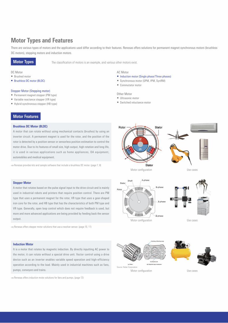
Motor Types and Features
⇒ Renesas provides kits and sample software that include a brushless DC motor. (page 7, 8)
⇒ Renesas offers stepper motor solutions that use a resolver sensor. (page 10, 11)
⇒ Renesas offers induction motor solutions for fans and pumps. (page 12)
Motor Features
There are various types of motors and the applications used differ according to their features. Renesas offers solutions for permanent magnet synchronous motors (brushless
DC motors), stepping motors and induction motors.
Motor Types The classifi cation of motors is an example, and various other motors exist.
AC Motor Induction motor (Single phase/Three phases) Synchronous motor (SPM, IPM, SynRM) Commutator motor
Stepper Motor (Stepping motor) Permanent magnet stepper (PM type) Variable reactance stepper (VR type) Hybrid synchronous stepper (HB type)
DC Motor Brushed motor Brushless DC motor (BLDC)
Other Motor Ultrasonic motor Switched reluctance motor
Brushless DC Motor (BLDC)
A motor that can rotate without using mechanical contacts (brushes) by using an
inverter circuit. A permanent magnet is used for the rotor, and the position of the
rotor is detected by a position sensor or sensorless position estimation to control the
motor drive. Due to its features of small size, high output, high rotation and long life,
it is used in various applications such as home appliances, OA equipment,
automobiles and medical equipment.
Stepper Motor
A motor that rotates based on the pulse signal input to the drive circuit and is mainly
used in industrial robots and printers that require position control. There are PM
type that uses a permanent magnet for the rotor, VR type that uses a gear-shaped
iron core for the rotor, and HB type that has the characteristics of both PM type and
VR type. Generally, open loop control which does not require feedback is used, but
more and more advanced applications are being provided by feeding back the sensor
output.
Induction Motor
It is a motor that rotates by magnetic induction. By directly inputting AC power to
the motor, it can rotate without a special drive unit. Vector control using a drive
device such as an inverter enables variable speed operation and high-efficiency
operation according to the load. Mainly used in industrial machines such as fans,
pumps, conveyors and trains.
Motor confi guration
Motor confi gurationSource: Nidec Corporation
Use cases
Motor confi guration Use cases
A-phase
B-phase
A-phase
B-phase
Rotor
StatorShaft
Use cases

04-05
Motor Control MethodIntroduces the method for driving the motor. Renesas has released 120-degree conducting control (Trapezoidal control) and vector control as sample software. Each has a
feature and is selected according to the purpose. It can be downloaded from the WEB and can be used as a reference for your program.
Position Sensor of MotorThe required sensor is different between when controlling the "motor speed" like a fan and when controlling the "motor position" like a robot. Each sensor has its own
characteristics, and the appropriate sensor is used according to the application. Renesas offers sample software that uses Hall sensor, Encoder, Resolver, and Inductive
position sensor, which are typical motor control position sensors. We also provide sample software for "position sensorless" control that does not use these position sensors.
Image of energization pattern for 120-degree conducting control
120-Degree Conducting Control (Square Wave Control)
Features Simple control method with low software load It is vulnerable to load fluctuation due to the control method that does not
detect current Precision and efficiency are inferior to vector control
In this control, two of the three coils of the BLDC motor are energized, and six energizing patterns are switched.
Vector Control
Features Advanced control method that detects current and performs fine control Highly accurate and efficient control can be realized Complex processing is required, and software load is high
In this control, by energizing all three coils and fi nely controlling the rotating magnetic fi eld, smoother driving is possible compared to 120-degree control. A feature of vector control is that the three-phase AC values are coordinate-converted into two-phase DC values to facilitate control. Image of coordinate conversion by vector control (3-phase motor)
q-axis
d-axisU-axis
W-axis V-axis
Hall Sensor
It is mainly used as an output corresponding to the switching of energization of 120-degree conducting control using three Hall sensors.
It is also possible to control the speed from the output of the hall sensor. Because of its low cost, the output may be used for purposes such as functional safety. Motor with hall sensor
Rotor
Hall IC
Hall IC
Hall IC
Coil
Stator
Encoder
There are optical encoders using light emitting/training elements and slits, and magnetic encoders using magnetic sensors.
Wide lineup from inexpensive low resolution to expensive high resolution. High resolution encoders are used in robots and AC servos. There is also an absolute type that can detect the absolute position.
Encoder
Resolver
A sensor that detects the position from the magnetic fluctuation between the rotor and stator. It is highly resistant to external factors such as dust, heat, and vibration, and is mainly used in the automotive
and industrial fields. A resolver digital converter is used to obtain the analog signal at the output of the resolver and use it for control. High accuracy is possible by correcting/removing resolver winding error and output signal noise.⇒See page 10 for resolver digital converter
Motor with resolver
Inductive Position Sensors
A position sensor that uses electromagnetic induction detects the position using a coil. Strong against external factors such as dust, heat and vibration. There are products that do not use magnets for detection, and products that are made smaller by supplementing
the coil with a board pattern.⇒ See page 13 for Renesas inductive sensor
Induction sensor image

Renesas Solutions for Motor Types and Control MethodsRenesas provides kits and motor control software according to the motor type and control microcomputer. Since the sample software prepared for each kit differs, refer to
the appropriate solution from the correspondence table below.
Provided as a Kit by Renesas
It is necessary for the customer to prepare a motor with an optical encoder.
Motor Type Name of Kit UsedReference
Page
Vector Control 120-Degree Conducting Control
Sensorless Optical Encoder Resolver Sensorless Hall Sensor
Speed ControlSpeed / Position
ControlSpeed / Position
ControlSpeed Control Speed Control
BLDC
Evaluation System for BLDC Motor + CPU card
RTK0EMX270S00020BJ7 – – – –
24V Motor Control Evaluation System for RX23T
RTK0EM0006S01212BJ7 – *1 – – –
Motor Control Evaluation System for RAJ306010
RTK0EML2C0S01020BJ8 – – – –
Motor Type Name of Kit UsedReference
Page
Vector Control 120-Degree Conducting Control
Sensorless Optical Encoder Resolver Sensorless Hall Sensor
Speed ControlSpeed / Position
ControlSpeed / Position
ControlSpeed Control Speed Control
Induction motor Evaluation System for ACIM 12 *2 – – – –
BLDC24V Motor Control Evaluation system for RX24T +
Magnetic sensor12 – *3 – – –
Renesas Kit + Motor with Encoder
Sample Software/Application Note Provided by Renesas
Motor Type Name of Kit UsedReference
Page
Vector Control 120-Degree Conducting Control
Sensorless Optical Encoder Resolver Sensorless Hall Sensor
Speed ControlSpeed / Position
ControlSpeed / Position
ControlSpeed Control Speed Control
BLDC
Evaluation System for BLDC Motor + CPU card RTK0EMX270S00020BJ
7 – –
24V Motor Control Evaluation System for RX23T RTK0EM0006S01212BJ
7 – –
Motor Control Evaluation System for RAJ306010 RTK0EML2C0S01020BJ
8 – – –
RZ/T1 motion control solution kit RTK7910018D00000BU
8 – – – –
Stepping motorEvaluation System for Stepping Motor with Resolver RTK0EMX270S01020BJ
10, 11 – – – –
*1: Magnetic encoder is also available. (It is necessary to prepare a motor with a magnetic encoder.)
*2: It is necessary to prepare an induction motor and an inverter board.*3: It is necessary to prepare a BLDC motor and a magnetic sensor. Motor control using a magnetic encoder is possible.

06-07
Item Specification
Kit name Evaluation System for BLDC Motor
Kit model No. RTK0EMX270S00020BJ
Structure48V 5A Inverter board for BLDC motor
BLDC motor (TG-55L-KA)
Inverter specification
Rated voltage: 48V Rated current: 5A (RMS) Protect function: Overcurrent detection, others
Sample Software Supported MCUs
120-degree conducting control + Speed control(Hall, Sensorless)
RX23T, RX24T
Vector control + Speed control(Encoder, Sensorless)
RX13T*1,RX23T, RX24T, RX24U, RX66T, RX72T, RA6T1
Vector control + Position control(Encoder)
RX23T, RX24T, RX24U, RX66T, RX72T, RA6T1
Solutions for Permanent Magnet Synchronous Motor (BLDC Motor)Renesas offers permanent magnet synchronous motor solutions to support customers' evaluation and development. Supported devices differ, so please select a solution that
uses the product you are considering.
Evaluation System for BLDC Motor
CPU card, sample software, and development support tool are provided to enable motor control immediately after purchase.
Features Motor control kit that supports up to DC48V input. Compatible with Renesas Motor Workbench for easy debugging. Equipped with overcurrent protection function. Various motor control MCUs can be evaluated in combination with an optional CPU card.
Kit specifi cations
*1: Sensorless only.
Supported DevicesMCU: RX13T, RX23T, RX24T, RX24U, RX66T, RX72T, RA6T1Gate Driver: HIP4086ABZTMOSFET: RJK1054DPB, RJK0854DPBRegulator: ISL9001AIRNZ
* A kit that includes the RA6T1 CPU card in this inverter board is also available. “Motor Control Evaluation System for RA Family - RA6T1 Group”
Overall Structure
Motor
CPU card(Sold separately)
Emulator(Sold separately)
Inverter board
Renesas Motor Workbench
Sample Software Supported MCUs
120-degree conducting control + Speed control(Hall, Sensorless)
RL78/G1M, RL78/G1G, RL78/G14, RL78/G1F, RX23T, RX24T
Vector control + Speed control(Encoder, Sensorless)
RL78/G1F*1, RX13T*1, RX23T, RX24T*2, RX24U, RX66T, RX72T, RA6T1
Vector control + Position control(Encoder)
RX23T, RX24T*2, RX24U, RX66T, RX72T, RA6T1
Item Specification
Kit name 24V Motor Control Evaluation System for RX23T
Kit model No. RTK0EM0006S01212BJ
Structure
24V 2A Inverter board for BLDC motor
RX23T CPU card
BLDC motor (TG-55L-KA)
Inverter specification
Rated voltage: 24V Rated current: 2A (RMS) Protect function: Overcurrent detection, others
24V Motor Control Evaluation System for RX23T
Motor solution that includes CPU card. A learning kit which is the basis of the Evaluation System for BLDC Motor allows you to try various control methods.
Features Many CPU cards are made available, enabling motor control in various MCUs. Compatible with Renesas Motor Workbench for easy debugging. Various
sample software are available. Compatible with sample software for RL78/G1F 1-shunt vector control and
sensorless 120-degree conducting control with initial position detection function.
Supports vector control sample software and application note using RX24T magnetic sensor.
Supported DevicesMCU: RL78/G1G, RL78/G1F, RL78/G14, RL78/G1M, RX13T, RX23T, RX24T,
RX24U, RX66T, RX72TMOSFET: N0602N-S19-AY
Kit specifi cations
*1: Sensorless only.*2: Compatible with magnetic encoders.
24V Motor Control Evaluation System for RX23T
Evaluation System for BLDC Motor + CPU card

Solutions for Permanent Magnet Synchronous Motor (BLDC Motor)
Motor Control Evaluation System for RAJ306010
Easy to start motor evaluation with Renesas evaluation motor and sample software.
Features System miniaturization [Board size reduction by 50%] Motor control evaluation kit supports DC: 24V Easy development environment for BLDC motor
RZ/T1 Motion Control Solution Kit
Features Package includes all parts needed for motor control evaluation. Supports safe design and can be used for reference. Includes motion utility tool. The tool includes motor parameter setting and tuning functions. Supports
multiple motor control methods, including trapezoidal control and S-curve acceleration and deceleration control.
Sample code for servo control via the industrial Ethernet (EtherCAT, CiA402).
Support rich safety functions1. Over Voltage for 5V regulator2. Over/Under Voltage for charge pump voltage3. Over Current detection/protection by current sense4. TSD function
Configurable Gate current for slew rate controlOptimize for Power Loss and EMI
Self-align dead time generatorDecrease of the heat radiation value by the MOSFET.Improvement Power Loss.
Sensor-less driveCapable of very low speed control with high load
Double boostAllows to maintain Gate Drive Voltage (Example 12V)even if the supply voltage drops to low
Gate drive current up to 500 mACapable of high-speed switching control for MOSFETwith large CISS
28ch GP I/O
Safety & protect function
Monitor & Settingfunction
Firmware(Users)
RL78 MCU High-performance AFE
Generate pulse forMotor control
Power supplyvoltage monitor
function
ChargePump
Regulator
Position DetectionHall sensor orSensor-less
Pre-Driver
Supported Devices
Sample Software Supported Products
120-degree conducting control (Hall) RAJ306010
120-degree conducting control + Speed control (Hall) RAJ306010
120-degree conducting control + Speed control (Sensorless) RAJ306010
180-degree conducting control + Speed/position control (Encoder)*1 RAJ306010
Item Specification
Kit name Motor Control Evaluation System for RAJ306010
Kit model No. RTK0EML2C0S01020BJ
Structure24V Inverter board for BLDC motor
BLDC motor (TG-55L-KA)
Inverter specification Rated voltage: 24V Rated current: 420mA (RMS)Use included motor
Kit specifi cations
Sample Software Supported MPUs
Vector control + Speed control (Encoder) RZ/T1
Vector control + Position control (Encoder) RZ/T1
Item Specification
Kit name RZ/T1 Motion Control Solution Kit
Kit model No. RTK7910018D00000BU
Structure24V 15A Inverter board for BLDC motor
BLDC motor with encoder (MB057GA140)
Inverter specification
Rated voltage: 24V Rated current: 15A (RMS) Protect function: Overcurrent detection, others
Kit specifi cations
*1: Please prepare a motor with an encoder separately.
Please contact us via the web for kits that can be used with RAJ306001.
Part No. Package Operating Voltage (V) Applications
RAJ306010GNP *2 P-HTQFN64 (8mm × 8mm)[terminal compatible]
6 to 42V (LiB: 2 to 10 Cell) Power tool (36V), Gardening tool, Cord-less vacuum cleaner (8 to 10 cell), Cooling-fan (36V), etc.
*2: Ta: –40 to +85°C RAJ306001GNP, RAJ306010GNP Ta: –40 to +105°C RAJ306001ZGNP, RAJ306010ZGNP
Motion Utility Tool
Overall Structure RZ/T1 CPU board, low voltage 2-axis drive inverter board Motion Utility Tool AC servo motor Simple probe for debugging (IAR Systems I-jet Lite)
Supported DevicesMPU: RZ/T1MOSFET: RJK1003DPNReceiver: ISL32173ETransmitter: ISL32179ETransceiver: ISL41387
RZ/T1 Motion Control Solution Kit
Motor Control Evaluation System for RAJ306010

08-09
Solutions for Permanent Magnet Synchronous Motor (BLDC Motor)
Recommended Products
MCUs and MPUs
Motor control IC (Integrated product of MCU and gate driver)
Analog, Power devices
Part No. Operating Frequency Key Features
RL78/G1M 20MHz 8-bit MCU, 5V Operation, Less pin package, Specialized for 120-degree conduction control
RL78/G1G 24MHz 16-bit MCU, 5V operation, Less pin package
RL78/G14 32MHz 16-bit MCU, 5V operation, Less pin package, Various line up
RL78/G1F 32MHz 16-bit MCU, 5V operation, Less pin package, Built-in comparator and PGA*2
RX13T 32MHz 32-bit MCU, FPU*1, 5V operation, Built-in PGA*2
RX23T 40MHz 32-bit MCU, FPU*1, 5V operation
RX24T 80MHz 32-bit MCU, FPU*1, 5V operation, Built-in PGA*2, 2 motor control
RX24U 80MHz 32-bit MCU, FPU*1, 5V operation, Built-in PGA*2, 2 motor control
RX66T 160MHz 32-bit MCU, FPU*1, 5V operation, Built-in PGA*2,3, 4 motor control, Security module
RX72T 200MHz 32-bit MCU, FPU*1, 5V operation, Built-in PGA*2,3, Built-in TFU*4, 4 motor control, Security module
RA6T1 120MHz 32-bit MCU, Arm Cortex-M4 Processor, Built-in PGA*2, 3, 2 motor control, Security module
RZ/T1 300/450/600MHz 32-bit MPU, Arm Cortex-R4 Processor, FPU*1, Absolute encoder I/F, R-IN engine
Category Part No. Key Features
MOSFET
N0602N-S19-AY Nch Power MOSFET, 60V/100A, RDS(on) = 4.6 m
RJK0854DPB Nch Power MOSFET, 80V/25A, RDS(on) = 13 mΩ max.
RJK1054DPB Nch Power MOSFET, 100V/20A, RDS(on) = 22 mΩ max.
RJK1003DPN-A0 Nch Power MOSFET, 100V/50A, RDS(on) = 11 mΩ max.
Gate Driver HIP4086ABZT 3 phase MOSFET driver, 80V, 500mA
RegulatorISL9001AIRNZ 2.3 to 6.5V operation, PSRR: 90dB@1kHz, Low power
ISL9005AIRNZ 2.3 to 6.5V operation, PSRR: 75dB@1kHz, Low power
RS-485/RS-422
ISL32173EFVZ RS-485/RS-422 receiver, 3.0 to 5.5V operation
ISL3159E RS-485/RS-422 transceiver, 3.0 to 5.5V operation, fail-safety function
ISL8485E RS-485/RS-422 transceiver, 3.0 to 5.5V operation
RS-422 ISL32179EFRZ RS-422 transmitter, 3.0 to 5.5V operation, Low power
RS-485/RS-232 ISL41387IRZ RS-485/RS-232 transceiver, ±15kV ESD
Part No. Operating Frequency Key Features
RAJ306010 32MHz Built-in Rl78/G1F, gate driver (6 to 42V)
*1: Floating Point Unit*2: Programmable Gain Amplifier*3: Pseudo-Differential PGA*4: Arithmetic Unit for Trigonometric Functions

Solutions for Stepping MotorResolver motor control solutions featuring superlative cost performance
Resolver Motor Control Solutions
These resolver-based motor control solutions are motor control systems for industrial and consumer applications realized by combining resolver-to-digital converter (RDC) ICs and RX Family microcontrollers (MCUs).It is possible to easily control a resolver-based stepping motor or brushless DC motor using the driver software of the microcontroller. Solution kits, sample code, development support tools, and application notes for motors with resolvers are provided, so motor control using resolvers can be started immediately.
Features High-precision motor control is possible even in the harsh environments with heat, dust, or vibration. Realize high-precision control at low cost using a new type of resolver control with superlative cost performance. Resolver signal gain, phase, and angle error are automatically corrected through the driver API that can be used in combination with an RX MCU to achieve high precision.
System configuration
Motor Control Solutions for Stepping Motors with Resolvers
In resolver-based motor control solutions, the RDC IC and RX MCU process signals from the resolver as angle information, and the RX MCU controls the motor. A dedicated driver for the RDC IC is provided on the RX MCU, and resolver processing can be easily performed using the API.
Using a portion of the MCU functions makes it possible to simplify the RDC IC and thereby lower its cost.
Solution ContentsStepping motor with resolver: New motor manufactured by MinebeaMitsumi Inc.RX24T: MCU for motor controlResolver-to-digital converter: IC that converts resolver output into digital signalSolution kit: All items necessary for controlling a stepping motor with resolver are providedSupport tool: Development support tool essential for motor control debugging
Stepping motors with resolvers and resolver motor control solutions developed by collaboration between MinebeaMitsumi Inc. and Renesas make it possible to servo control the stepping motor which is normally controlled by the open loop.
This solution realizes many advantages such as low noise, low vibration, low power consumption and maximization of motor torque.
Ics, software, development kits, and development support tools for resolver control and motor control are available.

10-11
Solutions for Stepping Motor
Evaluation System for Stepping Motor with Resolver
Item Specification
Kit name Evaluation System for Stepping Motor with Resolver
Kit model No. RTK0EMX270S01020BJ
Structure
48V 5A Inverter board for stepping motor
RX24T with RDC IC CPU card
Stepping motor with Resolver (Minebea Mitsumi)
Inverter specification
Rated voltage: 48V Rated current: 2A (RMS) Detect function: Phase current, Bus voltage Protect function: Overcurrent protection
Kit specifications
Recommended Products
MCUs
Analog, Power devices
Part No. Operating Frequency Key Features
RX23T 40MHz 32-bit MCU, FPU*1, 5V operation
RX24T 80MHz 32-bit MCU, FPU*1, 5V operation, PGA*2, 2 motor control
RX66T 160MHz 32-bit MCU, FPU*1, 5V operation, PGA*2,3, 4 motor control, Security module
RX72M 240MHz 32-bit MCU, Double precision FPU*1, Built-in TFU*4, Security module, EtherCAT® compatible
Category Part No. Key Features
RDC-ICRAA3064002GFP (85°C)
RAA3064003GFP (105°C)
Single-phase induced/Two phase output
Rectangle waveform 5/10/20kHz, 2.5Vp-p
Motor Driver HIP4082 80V, 1.25A Peak Driver
MOSFETRJK0854DPB N-Channel 80V, 25A, 10mΩ typ.
RJK1054DPB N-Channel 100V, 20A, 17mΩ typ.
AC/DC ISL6840
1A MOSFET gate driver
60µA start-up current, 100µA maximum
25ns propagation delay current sense to output
DC/DC ISL85033 Wide VIN Dual Standard Buck Regulator With 3A/3A Continuous Output Current
LDO ISL80505 500mA LDO
RS-485/RS-422ISL8485E ESD Protected to ±15kV, 5V, Low Power, High Speed Rate Limited, RS-485/RS-422 Transceivers
ISL3159E 40Mbps, 5V, fail safety, RS-485/RS-422 Transceivers
*1: Floating Point Unit*2: Programmable Gain Amplifier*3: Pseudo-Differential PGA*4: Arithmetic Unit for Trigonometric Functions
Sample Software Supported MCUs
Vector control + Speed control (Resolver) RX23T, RX24T, RX66T, RX72M
Vector control + Position control (Resolver) RX23T, RX24T, RX66T, RX72M
Supports RS485, CAN, pulse train command, general-purpose input/output for external device communication as the I/F specification of the kit.
Equipped with on-board emulator circuit (flash programming circuit).
Evaluation System for Stepping Motor with Resolver

Solutions for AC Induction MotorThree-phase induction motor solution provides inverter control software to be embedded in a motor control MCU. By providing an inverter control software with a high level of development diffi culty, you can easily and reasonably develop a customer-specifi c inverter.* This solution uses an inverter board made by a partner and does not provide a kit from Renesas.
Evaluation System for ACIM
Renesas can provide CPU cards, sample software, application notes, development support tools, and can control induction motors in combination with partner-made inverter boads.
Features Equipped with speed sensorless vector control function can remove speed sensor to reduce BOM cost and improve reliability. Compatible with Renesas Motor Workbench (motor control development support tool), for easy debugging. Built-in over current/over voltage/over temperature protection function, enables safe evaluation. Various motor control MCUs can be evaluated in combination with an optional CPU card. High voltage inverter board is compatible with AC85 to 265Vrms input(Need to be purchased separately from Desk Top Lab Co.,Ltd).
Evaluation Environment Specifi cations
Solutions Using Magnetic Sensors
Motor Control with Magnetic Sensor
Solution to control motor by combining with motor with magnetic sensorRenesas have released sample software and application notes that can correct the sensor output, which can be used as a reference for motor control using magnetic sensors.The motor with magnetic sensor used in this solution is not provided as a kit from Renesas.
Sample Software Supported MCUs
Vector control + Speed control (Sensorless) RX13T, RX66T
Supported DevicesMCU: RX13T, RX66T
Item Specification
StructureT1102 inverter board
RX13T CPU card, RX66T CPU card
Inverter specification
Rated voltage: AC 85 to 265V Rated current: 15A (RMS) Protect function: Overcurrent protection, others
Overall Structure
ACIM
CPU card
Emulator(Sold separately)
T1102 inverter board
Renesas Motor Workbench
Features Provide sample software and application notes for magnetic sensors with
analog output and digital output. The analog output magnetic sensor also has an output error correction function. Compatible with Renesas Motor Workbench, a motor control development
support tool, for easy debugging. Equipped with protection functions such as overcurrent and overvoltage
detection for safe evaluation.* Magnetic sensor manufactured by TDK Corporation is used to check the operation of this
sample software.
Overall Structure
Sample Software Supported MCUs
Vector control + Speed control (Magnetic sensor) RX24T
Vector control + Position control (Magnetic sensor) RX24T
Supported DevicesMCU: RX24TMOSFET: N0602N-S19-AY
Item Specification
Structure
24V 2A Inverter board for BLDC motor
RX24T CPU card
BLDC motor with magnetic sensor
Inverter specification
Rated voltage: 24V Rated current: 2A (RMS) Protect function: Overcurrent detection, others
Evaluation Environment Specifi cations
BLDC motor withmagnet sensor Inverter board
(24V Motor Control Evaluation system for RX23T)
Emulator(Sold separately)
Renesas Motor Workbench
CPU card

12-13
Solutions Using Inductive Position Sensors IPS2200 (Inductive Position Sensor)
This is thin, lightweight and cost effective with stray magnetic fi eld immunity and contributes to the design for industrial motor. This is ideal for industrial and medical motor commutation and robot application.
Features For control of electrical motor (especially BLDC motor) Power-supply voltage: 3.3V or 5V Support up to 250,000 rpm, low latency (<10µs) Magnet-free, thin, lightweight and low-cost solution High stray magnetic field immunity Sine/cosine (analog) output Support multiple pole pairs Operating temperature: –40°C to +125°C TSSOP-16
IPS2200STKIT
This is the kit for IPS2200, which includes the detection part of the position sensor and the interface board with PC. By combining with the dedicated GUI, you can easily visualize the angle.* This kit does not include a motor.
This kit is not designed to perform motor control but to check the output information from the position sensor.
This is a sensor detecting the position of the target metal based on the electromagnetic induction of the coil. The sensing element of IPS2200 enables to match the number of target sectors to pole pairs of the motor to
maximize accuracy. Sectors can be mounted both to shaft axis (on-axis) and shaft side (off-axis) of the motor, which increases the degree of freedom of the design.
This is thin and lightweight with one-tenth thickness and one-hundredth weight of the existing resolvers at maximum.
Degree of freedom for mounting method and design ofpole number
Dedicated GUI
Motor axis side
1-pole Multi-pole
Motor axis over
USB
Inductive Sensor Processing IC (IPS2200 Series)
Part No. Operation Voltage Operation Temperature Rated Speed Output Type Safety Function Package Provide
IPS2200BI1R3.0V to 3.6V or
4.5V to 5.5VTa = –40°C to +125°C
Max. 250.000 rpm (Electric
angle)
sin/cos (Differential or
single ended)
Overvoltage detection,
reverse polarity detection
output, short circuit
protection
TSSOP-16 Pin
(5.1mm × 6.4mm)
13" reel - 4000 IC/reel
IPS2200BI1W 7" reel - 500 IC/reel
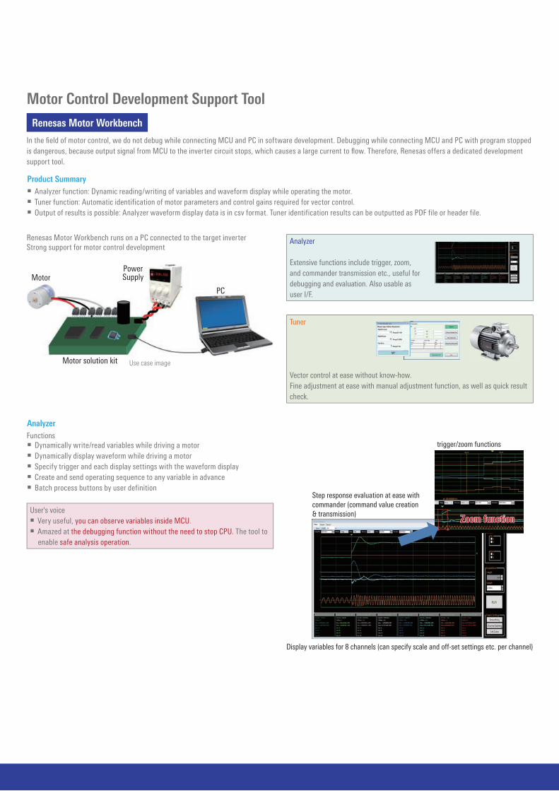
Motor Control Development Support Tool
Renesas Motor Workbench
In the fi eld of motor control, we do not debug while connecting MCU and PC in software development. Debugging while connecting MCU and PC with program stopped is dangerous, because output signal from MCU to the inverter circuit stops, which causes a large current to fl ow. Therefore, Renesas offers a dedicated development support tool.
Product Summary Analyzer function: Dynamic reading/writing of variables and waveform display while operating the motor. Tuner function: Automatic identification of motor parameters and control gains required for vector control. Output of results is possible: Analyzer waveform display data is in csv format. Tuner identification results can be outputted as PDF file or header file.
AnalyzerFunctions Dynamically write/read variables while driving a motor Dynamically display waveform while driving a motor Specify trigger and each display settings with the waveform display Create and send operating sequence to any variable in advance Batch process buttons by user definition
Renesas Motor Workbench runs on a PC connected to the target inverterStrong support for motor control development
Use case image
Motor
Motor solution kit
PowerSupply
PC
Analyzer
Extensive functions include trigger, zoom, and commander transmission etc., useful fordebugging and evaluation. Also usable asuser I/F.
Tuner
Vector control at ease without know-how. Fine adjustment at ease with manual adjustment function, as well as quick result check.
User's voice Very useful, you can observe variables inside MCU. Amazed at the debugging function without the need to stop CPU. The tool to
enable safe analysis operation.
Step response evaluation at ease withcommander (command value creation& transmission)
Display variables for 8 channels (can specify scale and off-set settings etc. per channel)
Easy analysis withtrigger/zoom functions
Zoom function
14-15
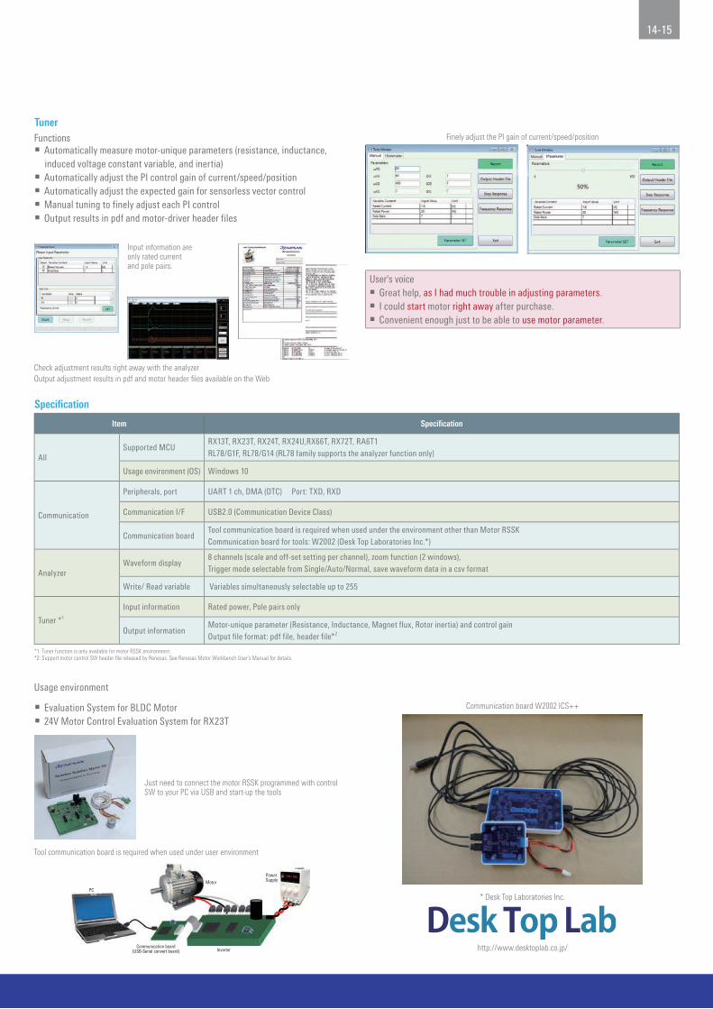
TunerFunctions Automatically measure motor-unique parameters (resistance, inductance,
induced voltage constant variable, and inertia) Automatically adjust the PI control gain of current/speed/position Automatically adjust the expected gain for sensorless vector control Manual tuning to finely adjust each PI control Output results in pdf and motor-driver header files
User's voice Great help, as I had much trouble in adjusting parameters. I could start motor right away after purchase. Convenient enough just to be able to use motor parameter.
Finely adjust the PI gain of current/speed/position
Communication board W2002 ICS++
* Desk Top Laboratories Inc.
http://www.desktoplab.co.jp/
Input information are only rated current and pole pairs.
Check adjustment results right away with the analyzerOutput adjustment results in pdf and motor header fi les available on the Web
Just need to connect the motor RSSK programmed with control SW to your PC via USB and start-up the tools
Specification
Item Specification
AllSupported MCU
RX13T, RX23T, RX24T, RX24U,RX66T, RX72T, RA6T1RL78/G1F, RL78/G14 (RL78 family supports the analyzer function only)
Usage environment (OS) Windows 10
Communication
Peripherals, port UART 1 ch, DMA (DTC) Port: TXD, RXD
Communication I/F USB2.0 (Communication Device Class)
Communication boardTool communication board is required when used under the environment other than Motor RSSKCommunication board for tools: W2002 (Desk Top Laboratories Inc.*)
AnalyzerWaveform display
8 channels (scale and off-set setting per channel), zoom function (2 windows),Trigger mode selectable from Single/Auto/Normal, save waveform data in a csv format
Write/ Read variable Variables simultaneously selectable up to 255
Tuner *1
Input information Rated power, Pole pairs only
Output informationMotor-unique parameter (Resistance, Inductance, Magnet flux, Rotor inertia) and control gainOutput file format: pdf file, header file*2
*1: Tuner function is only available for motor RSSK environment.*2: Support motor control SW header file released by Renesas. See Renesas Motor Workbench User’s Manual for details.
Usage environment
Evaluation System for BLDC Motor 24V Motor Control Evaluation System for RX23T
Tool communication board is required when used under user environment
PC
Motor
InverterCommunication board
(USB-Serial convert board)
PowerSupply

RAA227063 3-Phase Smart Gate Drivers
RAA227063 Smart 3-Phase
System Integration (Smart Gate Driver with Built-in Power Supply for System and High Accuracy Amp for 3-Shunt)
Support rich safety functions1. UV protection by VM2. OV/UV/OC protection by buck-boost regulator 3. UV protection by charge pump4. OC protection by current sense5. OC protection by MOSFET VDS6. Thermal Warning / Thermal Shut Down7. Reverse battery polarity protection (Additional external circuit)
Equip with high efficiency amplifier useful multipurpose • Differential amplifiers: 3ch (3-Shunt, Hall sensor, Sensor-less)• Gain amplifier for Back-EMF sense
Self-Align Dead Time (Adaptive Dead Time)Decrease heat radiation by the MOSFET. Reduce power loss
Adjustment function of Source /Sink currentOptimize for power loss and EMI
Sensor-less driveCapable of very low speed control with high load
Gate drive current up to 1A/2ACapable of high-speed switching control for MOSFET with large CISS
Safety Protection Function
Monitor & Setting Function
Firmware(User’s)
MCU RAA227063
Generate Pulse for Motor control
Power Supply Voltage Monitor
Function
ChargePump
SWRegulator(Buck-Boost)
LDO
Position DetectionHall Sensor or
Sensor-less
Gate-Driver(3ch Half Bridge)
Development Tool
Easy to Connect with Renesas CPU Card, Start to Evaluate by Sample Firmware of Renesas MCU PCB size: 14.1cm x 16.0cm Power input: 4.5V to 60V, motor driving MOSFETs are rated at 80V 132A. MCU connectors are compatible to Renesas RL78/G1F, RX23T,
and RA6T1 CPU card interface. (Has interface to MCU for motor current & voltage sensing, PWM signals, fault condition, enable IC, SPI connection, etc.)
EVB for RAA227063 (RTK227063DE000BU)CPU Card
(RL78/G1F, RX23T, RA6T1)
Product PKG Operating Voltage (V) Applications
RAA227063*1 48 Ld QFN
(7mm × 7mm)4.5 to 60V
Power tool, Gardening tool, Cord-less vacuum cleaner,
Cooling-fan, Water pump, Air pump, AGV, Robotics, etc.*1: RAA2270634GNP#MA0: Reel 250pcs Ta= -40 to 125 °C RAA2270634GNP#HA0: Reel 4k pcs Ta= -40 to 125 °C
Inquiry windowPlease contact customer support via the website for further information. https://www.renesas.com/us/en/

16-17
Recommended Products: MCUs and MPUs
RL78 Family
Part No. Pin Number ROM (KB) RAM (KB) Operating Frequency Power-supply Voltage
RL78/G1430 to 64
16 to 64 2.5 to 5.5
32MHz 1.6 to 5.5V96 to 512 12 to 48
80 to 100
RL78/G1F 24 to 64 32/64 5.5 32MHz 1.6 to 5.5V
RL78/G1G 30 to 44 8/16 1.5 24MHz 2.7 to 5.5V
RL78/G1M 20 4/8 0.512/1 20MHz 2.0 to 5.5V
RX Family
Part No. Pin Number ROM (KB) RAM (KB) Operating Frequency Power-supply Voltage
RX13T 32 to 48 64 to 128 12 32MHz 2.7 to 5.5V
RX23T 48 to 64 64 to 128 12 40MHz 2.7 to 5.5V
RX24T 64 to 100 128 to 512 16 to 32 80MHz 2.7 to 5.5V
RX24U 100 to 144 256 to 512 32 80MHz 2.7 to 5.5V
RX66T 64 to 144 256 to 1024 64 to 128 160MHz 2.7 to 5.5V
RX72T 100 to 144 512 to 1024 128 200MHz 2.7 to 5.5V
RZ Family
Part No. Pin Number ROM (KB) RAM (KB) Operating Frequency Power-supply Voltage
RZ/T1 176/320 0 544 to 1568 600MHz 3.0 to 3.6V
RZ/T1-M 112 0 544 to 1568 450MHz 3.0 to 3.6V
RA Family
Part No. Pin Number ROM (KB) RAM (KB) Operating Frequency Power-supply Voltage
RA6T1 64/100 256/512 64 120MHz 3.0 to 3.6V
RA6T2 48/64/100 512 64 240MHz 3.0 to 3.6V

Recommended Products: Motor Sensor Processing IC, Motor Control IC
RDC IC (Resolver to Digital Converter)
Part No.
Resolver Driving Block Converter BlockAmplifier
Circuit BlockControl Block
Conversion
Error
Power-supply
Voltage
Power-supply
Current
Operating
Ambient
Temperature
Package
InputExcitation
Signal Output
Over
Temperature
Detection
Circuit
Differential
Amplifier
Circuit
Signal
Conversion
Circuit
Disconnection
Detection
Circuit
Differential
Amplifier
Circuit
Communication
Function
Operating
Frequency
RAA3064002GFP
Square wave:
5/10/20 kHz
Alternating
current:
35mAp-p
(Max.)
Built-in
Gain Variable:
2, 4, 8, 16.5
times
Angle error
correction
function,
Internal circuit
error
correction
function
Detect
disconnection
from signal
amplitude
2 ch (Support
differential
input), Gain
variable: 10, 25
times
SPI interface
(Max. 1MHz)4MHz ±0.2°
VDD =
4.5-5.5V,
IOVDD = AVDD
Maximum
operating
current: 20 mA
(Typ.)
–40°C to
+85°C
LQFP-48pin
(7mm × 7mm)
RAA3064003GFP–40°C to
+105°C
3 Phase BLDC Motor Control (RAJ306000 Series)
Part No.Motor Drive
VoltageMCU
Communication
I/FTimer
Guaranteed
Operating
Temperature Range
5V Regulator
AccuracyA/D Converter
Pre-Driver Block
Safety Function PackageGate Drive Peak
Current
Boosting
Function
RAJ306010GNP/ZGNP VM = 6V to 42V
RL78G1F (Flash
ROM: 64KB, RAM:
5.5KB)
3 units (SPI: 2ch,
IIC: 2ch, UART:
1ch)
16-bit timer: 8ch
GNP: Ta = –40°C to
+85°C,
ZGNP: Ta = –40°C to
+105°C
5V ± 1%
(Ta = 25°C)
9ch (Resolution:
10-bit)
500mA
Drive peak current
supporting up to
500mA, Dead time
adjustment
function, Gate
current adjustment
function
Double boost /
Single boost
switch
Over temperature
protection,
Overvoltage
detection,
Overcurrent
detection/
protection,
Output phase
overcurrent
detection/
protection, Low
voltage
detection/
protection
P-HTQFN-64 Pin
(8mm × 8mm)
Inductive Sensor Processing IC (IPS2200 Series)
Part No. Operation Voltage Operation Temperature Rated Speed Output Type Safety Function Package Provide
IPS2200BI1R3.0V to 3.6V or
4.5V to 5.5VTa = –40°C to +125°C
Max. 250.000 rpm (Electric
angle)
sin/cos (Differential or
single ended)
Overvoltage detection,
reverse polarity detection
output, short circuit
protection
TSSOP-16 Pin
(5.1mm × 6.4mm)
13" reel - 4000 IC/reel
IPS2200BI1W 7" reel - 500 IC/reel
18-19
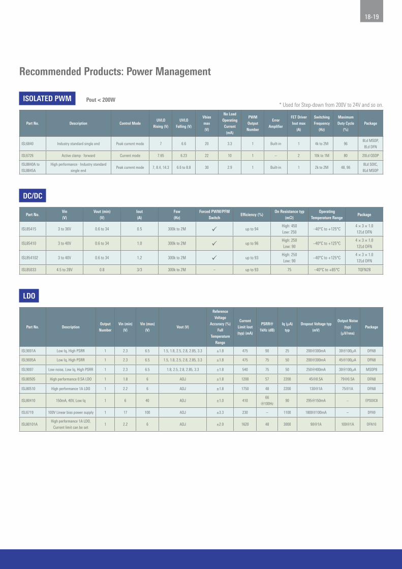
Recommended Products: Power Management
ISOLATED PWM
Part No. Description Control ModeUVLO
Rising (V)
UVLO
Falling (V)
Vbias
max
(V)
No Load
Operating
Current
(mA)
PWM
Output
Number
Error
Amplifier
FET Driver
Iout max
(A)
Switching
Frequency
(Hz)
Maximum
Duty Cycle
(%)
Package
ISL6840 Industry standard single end Peak current mode 7 6.6 20 3.3 1 Built-in 1 4k to 2M 968Ld MSOP,
8Ld DFN
ISL6726 Active clamp · forward Current mode 7.65 6.23 22 10 1 – 2 10k to 1M 80 20Ld QSOP
ISL8840A to
ISL8845A
High performance · Industry standard
single endPeak current mode 7, 8.4, 14.3 6.6 to 8.8 30 2.9 1 Built-in 1 2k to 2M 48, 96
8Ld SOIC,
8Ld MSOP
LDO
Part No. DescriptionOutput
Number
Vin (min)
(V)
Vin (max)
(V)Vout (V)
Reference
Voltage
Accuracy (%)
Full
Temperature
Range
Current
Limit Iout
(typ) (mA)
PSRR@
1kHz (dB)
Iq (µA)
typ
Dropout Voltage typ
(mV)
Output Noise
(typ)
(µV/rms)
Package
ISL9001A Low Iq, High PSRR 1 2.3 6.5 1.5, 1.8, 2.5, 2.8, 2.85, 3.3 ±1.8 475 90 25 200@300mA 30@100µA DFN8
ISL9005A Low Iq, High PSRR 1 2.3 6.5 1.5, 1.8, 2.5, 2.8, 2.85, 3.3 ±1.8 475 75 50 200@300mA 45@100µA DFN8
ISL9007 Low noise, Low Iq, High PSRR 1 2.3 6.5 1.8, 2.5, 2.8, 2.85, 3.3 ±1.8 540 75 50 250@400mA 30@100µA MSOP8
ISL80505 High performance 0.5A LDO 1 1.8 6 ADJ ±1.8 1200 57 2200 [email protected] [email protected] DFN8
ISL80510 High performance 1A LDO 1 2.2 6 ADJ ±1.8 1750 48 2200 130@1A 75@1A DFN8
ISL80410 150mA, 40V, Low Iq 1 6 40 ADJ ±1.0 41066
@100Hz90 295@150mA – EPSOIC8
ISL6719 100V Linear bias power supply 1 17 100 ADJ ±3.3 230 – 1100 1800@100mA – DFN9
ISL80101AHigh performance 1A LDO,
Current limit can be set1 2.2 6 ADJ ±2.0 1620 48 3000 90@1A 100@1A DFN10
DC/DC
Part No.Vin (V)
Vout (min) (V)
Iout (A)
Fsw (Hz)
Forced PWM/PFM Switch
Efficiency (%)On Resistance typ
(mΩ)Operating
Temperature RangePackage
ISL85415 3 to 36V 0.6 to 34 0.5 300k to 2M up to 94High: 450
Low: 250–40°C to +125°C
4 × 3 × 1.0
12Ld DFN
ISL85410 3 to 40V 0.6 to 34 1.0 300k to 2M up to 96High: 250
Low: 90–40°C to +125°C
4 × 3 × 1.0
12Ld DFN
ISL854102 3 to 40V 0.6 to 34 1.2 300k to 2M up to 93High: 250
Low: 90–40°C to +125°C
4 × 3 × 1.0
12Ld DFN
ISL85033 4.5 to 28V 0.8 3/3 300k to 2M – up to 93 75 –40°C to +85°C TQFN28
Pout < 200W* Used for Step-down from 200V to 24V and so on.

Recommended Products: Gate Driver, MOSFET, Peripheral IC
Gate Driver: For MOSFET Driver Bridge
Part No.Maximum Boot
Strap Voltage (V)Maximum Bias
Voltage (V)Input System/Output System
Peak Pull-up/down Current (A)
Turn on/off Propagation Delay (nS)
Rising/Falling Time (nS)
Package Remarks
HIP2211 115 18 2/2 3/4 30/30 6/6 8 Ld SOIC, 8/10 Ld 4 × 4 DFN
HIP4082 95 15 4/4 1.4/1.3 75/55 9/9 16Ld PDIP, 16Ld SOIC
HIP4086A 95 15 6/6 1/1 20/10 10/10 20Ld PDIP, 20Ld SOIC 80V, 500mA, 3-Phase MOSFET Driver
Inverter Circuit: Power MOSFET
Part No. Nch/Pch Resisting Pressure Current ON Resistance (max) Package
RJK1054DPB Nch Single 100V 20A 22mΩ LFPAK
RJK0854DPB Nch Single 80V 25A 13mΩ LFPAK
RJK0454DPB Nch Single 40V 40A 4.9mΩ LFPAK
RJK0455DPB Nch Single 40V 45A 3.8mΩ LFPAK
RJK0456DPB Nch Single 40V 50A 3.2mΩ LFPAK
NP75N04YUK Nch Single 40V 75A 3.3mΩ HSON-8
NP50N04YUK Nch Single 40V 50A 4.8mΩ HSON-8
NP30N04QUK Nch Dual 40V 30A 8mΩ HSON-8
NP29N04QUK Nch Dual 40V 30A 10.1mΩ HSON-8
MOSFET Driver IGBT Gate Driver Coupler
ISL89411 PS9031ISL89410
Vs = 18V (max)Ipk = 2A (max)8Ld PDIP, SOIC
Vcc = 30V (max)Ioh/Iol = 2.2A/2.4A5Ld LSO5
5
3
1
2
4
SHIELD
Peripheral IC: RS-485 Transceiver
Type Duplex Part No. Data Rate Supply Voltage Temp Range Fail Safe Hot Plug Remarks
Low cost Transceiver Half ISL8485E 10Mbps 5V –40°C to +85°C / +125°C Open N
IEC61000 ESD
protection
Full function
TransceiverHalf ISL3152E / 55E / 58E
115k / 1M / 20Mbps 5V –40°C to +85°C Full Y Min. 2.4V High output voltageFull ISL3150E / 53E / 56E
High speed, Full
function
IEC61000 ESD
protection
Transceiver Half/Full
ISL3159E / 60E
40Mbps
5V
–40°C to +85°C / +125°C Full Y
Min. 2.1V High output voltage
ISL3179E / 80E 3.3V
±60V Overvoltage
protectionTransceiver
Half ISL32492E / 95E / 98E250k / 1M / 15Mbps 5V –40°C to +85°C Full Y
±25V Common mode voltage
Min. 2.0V High output voltage
@5VFull ISL32490E / 93E / 96E

20-21
MEMO
www.renesas.com
Notice1. Descriptions of circuits, software and other related information in this document are provided only to illustrate the operation of semiconductor products and application examples. You are fully responsible for the incorporation or any other use of the circuits, software, and information in the
design of your product or system. Renesas Electronics disclaims any and all liability for any losses and damages incurred by you or third parties arising from the use of these circuits, software, or information.2. Renesas Electronics hereby expressly disclaims any warranties against and liability for infringement or any other claims involving patents, copyrights, or other intellectual property rights of third parties, by or arising from the use of Renesas Electronics products or technical information described
in this document, including but not limited to, the product data, drawings, charts, programs, algorithms, and application examples.3. No license, express, implied or otherwise, is granted hereby under any patents, copyrights or other intellectual property rights of Renesas Electronics or others.4. You shall be responsible for determining what licenses are required from any third parties, and obtaining such licenses for the lawful import, export, manufacture, sales, utilization, distribution or other disposal of any products incorporating Renesas Electronics products, if required.5. You shall not alter, modify, copy, or reverse engineer any Renesas Electronics product, whether in whole or in part. Renesas Electronics disclaims any and all liability for any losses or damages incurred by you or third parties arising from such alteration, modification, copying or reverse
engineering.6. Renesas Electronics products are classified according to the following two quality grades: “Standard” and “High Quality”. The intended applications for each Renesas Electronics product depends on the product’s quality grade, as indicated below. "Standard": Computers; office equipment; communications equipment; test and measurement equipment; audio and visual equipment; home electronic appliances; machine tools; personal electronic equipment; industrial robots; etc. "High Quality": Transportation equipment (automobiles, trains, ships, etc.); traffic control (traffic lights); large-scale communication equipment; key financial terminal systems; safety control equipment; etc. Unless expressly designated as a high reliability product or a product for harsh environments in a Renesas Electronics data sheet or other Renesas Electronics document, Renesas Electronics products are not intended or authorized for use in products or systems that may pose a direct threat to
human life or bodily injury (artificial life support devices or systems; surgical implantations; etc.), or may cause serious property damage (space system; undersea repeaters; nuclear power control systems; aircraft control systems; key plant systems; military equipment; etc.). Renesas Electronics disclaims any and all liability for any damages or losses incurred by you or any third parties arising from the use of any Renesas Electronics product that is inconsistent with any Renesas Electronics data sheet, user’s manual or other Renesas Electronics document.
7. No semiconductor product is absolutely secure. Notwithstanding any security measures or features that may be implemented in Renesas Electronics hardware or software products, Renesas Electronics shall have absolutely no liability arising out of any vulnerability or security breach, including but not limited to any unauthorized access to or use of a Renesas Electronics product or a system that uses a Renesas Electronics product. RENESAS ELECTRONICS DOES NOT WARRANT OR GUARANTEE THAT RENESAS ELECTRONICS PRODUCTS, OR ANY SYSTEMS CREATED USING RENESAS ELECTRONICS PRODUCTS WILL BE INVULNERABLE OR FREE FROM CORRUPTION, ATTACK, VIRUSES, INTERFERENCE, HACKING, DATA LOSS OR THEFT, OR OTHER SECURITY INTRUSION (“Vulnerability Issues”). RENESAS ELECTRONICS DISCLAIMS ANY AND ALL RESPONSIBILITY OR LIABILITY ARISING FROM OR RELATED TO ANY VULNERABILITY ISSUES. FURTHERMORE, TO THE EXTENT PERMITTED BY APPLICABLE LAW, RENESAS ELECTRONICS DISCLAIMS ANY AND ALL WARRANTIES, EXPRESS OR IMPLIED, WITH RESPECT TO THIS DOCUMENT AND ANY RELATED OR ACCOMPANYING SOFTWARE OR HARDWARE, INCLUDING BUT NOT LIMITED TO THE IMPLIED WARRANTIES OF MERCHANTABILITY, OR FITNESS FOR A PARTICULAR PURPOSE.
8. When using Renesas Electronics products, refer to the latest product information (data sheets, user’s manuals, application notes, “General Notes for Handling and Using Semiconductor Devices” in the reliability handbook, etc.), and ensure that usage conditions are within the ranges specified by Renesas Electronics with respect to maximum ratings, operating power supply voltage range, heat dissipation characteristics, installation, etc. Renesas Electronics disclaims any and all liability for any malfunctions, failure or accident arising out of the use of Renesas Electronics products outside of such specified ranges.
9. Although Renesas Electronics endeavors to improve the quality and reliability of Renesas Electronics products, semiconductor products have specific characteristics, such as the occurrence of failure at a certain rate and malfunctions under certain use conditions. Unless designated as a high reliability product or a product for harsh environments in a Renesas Electronics data sheet or other Renesas Electronics document, Renesas Electronics products are not subject to radiation resistance design. You are responsible for implementing safety measures to guard against the possibility of bodily injury, injury or damage caused by fire, and/or danger to the public in the event of a failure or malfunction of Renesas Electronics products, such as safety design for hardware and software, including but not limited to redundancy, fire control and malfunction prevention, appropriate treatment for aging degradation or any other appropriate measures. Because the evaluation of microcomputer software alone is very difficult and impractical, you are responsible for evaluating the safety of the final products or systems manufactured by you.
10. Please contact a Renesas Electronics sales office for details as to environmental matters such as the environmental compatibility of each Renesas Electronics product. You are responsible for carefully and sufficiently investigating applicable laws and regulations that regulate the inclusion or use of controlled substances, including without limitation, the EU RoHS Directive, and using Renesas Electronics products in compliance with all these applicable laws and regulations. Renesas Electronics disclaims any and all liability for damages or losses occurring as a result of your noncompliance with applicable laws and regulations.
11. Renesas Electronics products and technologies shall not be used for or incorporated into any products or systems whose manufacture, use, or sale is prohibited under any applicable domestic or foreign laws or regulations. You shall comply with any applicable export control laws and regulations promulgated and administered by the governments of any countries asserting jurisdiction over the parties or transactions.
12. It is the responsibility of the buyer or distributor of Renesas Electronics products, or any other party who distributes, disposes of, or otherwise sells or transfers the product to a third party, to notify such third party in advance of the contents and conditions set forth in this document.13. This document shall not be reprinted, reproduced or duplicated in any form, in whole or in part, without prior written consent of Renesas Electronics.14. Please contact a Renesas Electronics sales office if you have any questions regarding the information contained in this document or Renesas Electronics products.(Note 1) “Renesas Electronics” as used in this document means Renesas Electronics Corporation and also includes its directly or indirectly controlled subsidiaries.(Note 2) “Renesas Electronics product(s)” means any product developed or manufactured by or for Renesas Electronics.
SALES OFFICESRefer to "http://www.renesas.com/" for the latest and detailed information.
Renesas Electronics CorporationTOYOSU FORESIA, 3-2-24 Toyosu, Koto-ku, Tokyo 135-0061, Japan
Renesas Electronics America Inc. Milpitas Campus1001 Murphy Ranch Road, Milpitas, CA 95035, U.S.A.Tel: +1-408-432-8888, Fax: +1-408-434-5351
Renesas Electronics America Inc. San Jose Campus6024 Silver Creek Valley Road, San Jose, CA 95138, USATel: +1-408-284-8200, Fax: +1-408-284-2775
Renesas Electronics Canada Limited9251 Yonge Street, Suite 8309 Richmond Hill, Ontario Canada L4C 9T3Tel: +1-905-237-2004
Renesas Electronics Europe GmbHArcadiastrasse 10, 40472 Düsseldorf, GermanyTel: +49-211-6503-0, Fax: +49-211-6503-1327
Renesas Electronics (China) Co., Ltd.Room 101-T01, Floor 1, Building 7, Yard No. 7, 8th Street, Shangdi, Haidian District, Beijing 100085, ChinaTel: +86-10-8235-1155, Fax: +86-10-8235-7679
Renesas Electronics (Shanghai) Co., Ltd.Unit 301, Tower A, Central Towers, 555 Langao Road, Putuo District, Shanghai 200333, ChinaTel: +86-21-2226-0888, Fax: +86-21-2226-0999
Renesas Electronics Hong Kong LimitedUnit 1601-1611, 16/F., Tower 2, Grand Century Place, 193 Prince Edward Road West, Mongkok, Kowloon, Hong KongTel: +852-2265-6688, Fax: +852 2886-9022
Renesas Electronics Taiwan Co., Ltd.13F, No. 363, Fu Shing North Road, Taipei 10543, TaiwanTel: +886-2-8175-9600, Fax: +886 2-8175-9670
Renesas Electronics Singapore Pte. Ltd.80 Bendemeer Road, #06-02 Singapore 339949Tel: +65-6213-0200, Fax: +65-6213-0300
Renesas Electronics Malaysia Sdn.Bhd.Unit No 3A-1 Level 3A Tower 8 UOA Business Park, No 1 Jalan Pengaturcara U1/51A, Seksyen U1, 40150 Shah Alam, Selangor, MalaysiaTel: +60-3-5022-1288, Fax: +60-3-5022-1290
Renesas Electronics India Pvt. Ltd.No.777C, 100 Feet Road, HAL 2nd Stage, Indiranagar, Bangalore 560 038, IndiaTel: +91-80-67208700
Renesas Electronics Korea Co., Ltd.17F, KAMCO Yangjae Tower, 262, Gangnam-daero, Gangnam-gu, Seoul, 06265 KoreaTel: +82-2-558-3737, Fax: +82-2-558-5338
(Rev.5.0-1 October 2020)
© 2021 Renesas Electronics Corporation.All rights reserved.
Document No. R30CA0165EJ0400