msc adams modelling of mechanical system in a400m crew
TRANSCRIPT
MSC Adams modelling of mechanical system in A400M Crew Entrance Door
David Lindberg
Division of Mechanics
Master Thesis Department of Management and Engineering
Linköping Institute of Technology, Sweden
LIU-IEI-TEK-A--12/01304—SE Linköping 2012


Dokumentslag Type of document Reg-nr Reg. No
REPORT-MSC. Thesis AIF288-2-RE-0496
Ägare Owner Datum Date Utgåva Issue Sida Page
David Lindberg 2012-06-06 A 1 (56) Fastställd av Confirmed by Infoklass Info. class Arkiveringsdata File
Anna Carlsson, Sven-Gunnar Eriksson Öppen Giltigt för Valid for
IN 5000356-289 Utg 5 10.05 Word Allmänblankett
Th
is d
ocum
en
t an
d t
he
in
form
atio
n c
on
tain
ed
he
rein
is
the
pro
pe
rty o
f S
aa
b A
B a
nd
mu
st
no
t b
e u
sed
, d
isclo
se
d
or
alte
red
with
ou
t S
aa
b A
B p
rior
wri
tte
n c
on
sen
t.
Ärende Subject Fördelning To
MSC Adams modelling of mechanical system
in A400M Crew Entrance Door
Anna Carlsson & Sven-Gunnar Eriksson
LIU – Peter Schmidt & Anders Klarbring
Abstract This report is an official version of the master thesis report, where some
pictures have been removed for Intellectual Property reasons.
Saab Aerostructures has developed the Crew Entrance Door (CED) for Airbus
A400M. Airbus has decided some different load cases for which the Crew
Entrance Door must be built to withstand without something breaking down.
The door is maneuvered by a mechanical system and the load cases are
essential for the sizing of the components in the mechanical system. Saab has
previously used MS Excel to analytically calculate resulting forces in the
mechanical system due to external and/or internal loads in the different load
cases. This report describes how the mechanical system for A400M Crew
Entrance Door instead can be modeled and solved numerically with the
computer program MSC Adams/View.
Creating a model of a mechanical system in MSC Adams/View proved to be
easy and fairly quick. The benefit of working with MSC Adams instead of MS
Excel is that it is quicker and more user friendly.
The major differences when comparing results were believed to be an effect of
comparing results from a kinematic model with results from a dynamic model.
Therefore it is in the Authors opinion that the analytical method to calculate
resulting forces with MS Excel can be replaced by numerical calculations with
MSC Adams/View. However, apart from calculating reaction forces there are
additional post-simulation calculations for which it is perhaps more beneficial
to use MS Excel. To do these post-simulation calculations in MS Excel it is
easy to use exported results from MSC Adams.
If Saab Aerostructures decide to start working with MSC Adams/View and if
Saab wants geometry to be imported to the model, then an advise from the
Author is to have a software installed which can convert step-files (*.stp or
*.step) to the MSC Adams preferred file format Parasolid (*.xmt_txt or *.x_t).
The software should also be able to repair geometry which will greatly increase
mass accuracy.

Dokumentslag Type of document Reg-nr Reg. No
REPORT-MSc. Thesis AIF288-2-RE-0496
Infoklass Info. class Utgåva Issue Sida Page
Öppen A 2 (56)
IN 5000356-289 Utg 5 10.05 Word Allmänblankett
Th
is d
ocum
en
t an
d t
he
in
form
atio
n c
on
tain
ed
he
rein
is
the
pro
pe
rty o
f S
aa
b A
B a
nd
mu
st
no
t b
e u
sed
, d
isclo
se
d
or
alte
red
with
ou
t S
aa
b A
B p
rior
wri
tte
n c
on
sen
t.
Preface I especially want to thank Sven-Gunnar Eriksson, Bengt Lundqvist and Anna
Carlsson at Saab Aerostructures for helping me understand the mechanical
system for A400M Crew Entrance Door. I am also greatly thankful to my other
colleagues at Saab Aerostructures for helping me with various problems that
arose during this work.
I am thankful to my supervisor Peter Schmidt and my examiner Anders
Klarbring at Linköping University for helping me structure my work.
I am also thankful to Magnus Bergelin and Per Hedlund at Saab for helping me
converting files and to Per Persson at Saab for helping me learn how MSC
Adams/View works.
I would also like to say thanks to my wife Annika, for her love and care.
Dokumentslag Type of document Reg-nr Reg. No
REPORT-MSc. Thesis AIF288-2-RE-0496
Infoklass Info. class Utgåva Issue Sida Page
Öppen A 3 (56)
IN 5000356-289 Utg 5 10.05 Word Allmänblankett
Th
is d
ocum
en
t an
d t
he
in
form
atio
n c
on
tain
ed
he
rein
is
the
pro
pe
rty o
f S
aa
b A
B a
nd
mu
st
no
t b
e u
sed
, d
isclo
se
d
or
alte
red
with
ou
t S
aa
b A
B p
rior
wri
tte
n c
on
sen
t.
Table of Content
1 INTRODUCTION ................................................................................... 5 1.1 Background .............................................................................................. 5
1.2 Purpose .................................................................................................... 5 1.3 Limitations ............................................................................................... 5 1.4 Airbus A400M ......................................................................................... 6 1.5 Load Cases ............................................................................................... 9 2 THEORY - MULTIBODY SYSTEMS ................................................. 10
2.1 Practical use of MBS-programs ............................................................. 10 2.2 Build a model ......................................................................................... 11
2.3 Simulation .............................................................................................. 15 3 METHOD .............................................................................................. 22 3.1 Building the model ................................................................................ 22 3.2 Applying loads on the model ................................................................. 31 4 RESULTS .............................................................................................. 37
4.1 Lifting the door ...................................................................................... 37
4.2 Jamming during lifting manoeuvre ........................................................ 43 4.3 Opening the door ................................................................................... 44 4.4 Opened door ........................................................................................... 46
4.5 Jettison manoeuvre ................................................................................ 48 5 DISCUSSION ........................................................................................ 51
5.1 Results .................................................................................................... 51 5.2 Use of the Contact function ................................................................... 52
5.3 Accurate mass ........................................................................................ 53 5.4 Importing CAD geometry ...................................................................... 54
5.5 Replacing MS Excel with MSC Adams ................................................ 54 6 CONCLUSION AND FUTURE WORK .............................................. 55 7 REFERENCES ...................................................................................... 56
APPENDIX A ................................................................................................. A-1

Dokumentslag Type of document Reg-nr Reg. No
REPORT-MSc. Thesis AIF288-2-RE-0496
Infoklass Info. class Utgåva Issue Sida Page
Öppen A 4 (56)
IN 5000356-289 Utg 5 10.05 Word Allmänblankett
Th
is d
ocum
en
t an
d t
he
in
form
atio
n c
on
tain
ed
he
rein
is
the
pro
pe
rty o
f S
aa
b A
B a
nd
mu
st
no
t b
e u
sed
, d
isclo
se
d
or
alte
red
with
ou
t S
aa
b A
B p
rior
wri
tte
n c
on
sen
t.
Dokumentslag Type of document Reg-nr Reg. No
REPORT-MSc. Thesis AIF288-2-RE-0496
Infoklass Info. class Utgåva Issue Sida Page
Öppen A 5 (56)
IN 5000356-289 Utg 5 10.05 Word Allmänblankett
Th
is d
ocum
en
t an
d t
he
in
form
atio
n c
on
tain
ed
he
rein
is
the
pro
pe
rty o
f S
aa
b A
B a
nd
mu
st
no
t b
e u
sed
, d
isclo
se
d
or
alte
red
with
ou
t S
aa
b A
B p
rior
wri
tte
n c
on
sen
t.
1 INTRODUCTION
1.1 Background
Saab has developed the Crew Entrance Door (CED) for Airbus A400M, a
military transport aircraft. The door is maneuvered by a mechanical system for
opening/closing and locking/unlocking. In addition the mechanical system can,
in case of emergency evacuation in flight, release the door from the aircraft
(jettison).
Airbus has decided some different load cases which the CED must be able to
withstand without something breaking down in the mechanical system. Saab
has previously used MS Excel to analytically calculate resulting forces in the
mechanical system due to external and/or internal loads in the different load
cases. The approach led to large and complex MS Excel sheets. This report
describes how the mechanical system for A400M Crew Entrance Door instead
can be modeled and solved numerically with the computer program MSC
Adams/View. The previous calculations using MS Excel are called analytical in
this report and the MSC Adams calculations are named numerical.
1.2 Purpose
The purpose with creating an MSC Adams model of the mechanical system for
A400M Crew Entrance Door is to see if this program can calculate resulting
forces in an easier and more comprehensive way than what is the case when
working analytically with MS Excel.
1.3 Limitations
All details on the door have not been modelled. Only the parts included in the
mechanical system and a few additional items such as door blade and doorway
has been modelled. The mass for the parts on the CED not belonging to the
mechanical system have all been added to a common mass applied on the door
blade.
In reality some additional steps called foldable steps are included in the
mechanical system, however due to project time limitations these have not been
modelled.
When jettisoning the door, it will be released from the aircraft after the hinges
have rotated more than during normal manoeuvring. The door is released
through a mechanism that is forcing apart a connection at the hinge line. In the
model this mechanism was simplified to just releasing the door at a certain
rotation of the hinges.
1.3.1 Assumptions
The mechanical system was modelled with rigid bodies and joints.
Consequently, an assumption has been made that the deformation of the bodies
can be neglected.
Dokumentslag Type of document Reg-nr Reg. No
REPORT-MSc. Thesis AIF288-2-RE-0496
Infoklass Info. class Utgåva Issue Sida Page
Öppen A 6 (56)
IN 5000356-289 Utg 5 10.05 Word Allmänblankett
Th
is d
ocum
en
t an
d t
he
in
form
atio
n c
on
tain
ed
he
rein
is
the
pro
pe
rty o
f S
aa
b A
B a
nd
mu
st
no
t b
e u
sed
, d
isclo
se
d
or
alte
red
with
ou
t S
aa
b A
B p
rior
wri
tte
n c
on
sen
t.
Friction has been modelled for the contact between rubber sealing and door
blade. On the lower side of the door the displacement was assumed to be
perpendicular to the surface of the rubber sealing (i.e. no shear displacement)
and therefore was friction in that region neglected.
Both of the two assumptions for rigid bodies and friction were also made in the
previous analytical method.
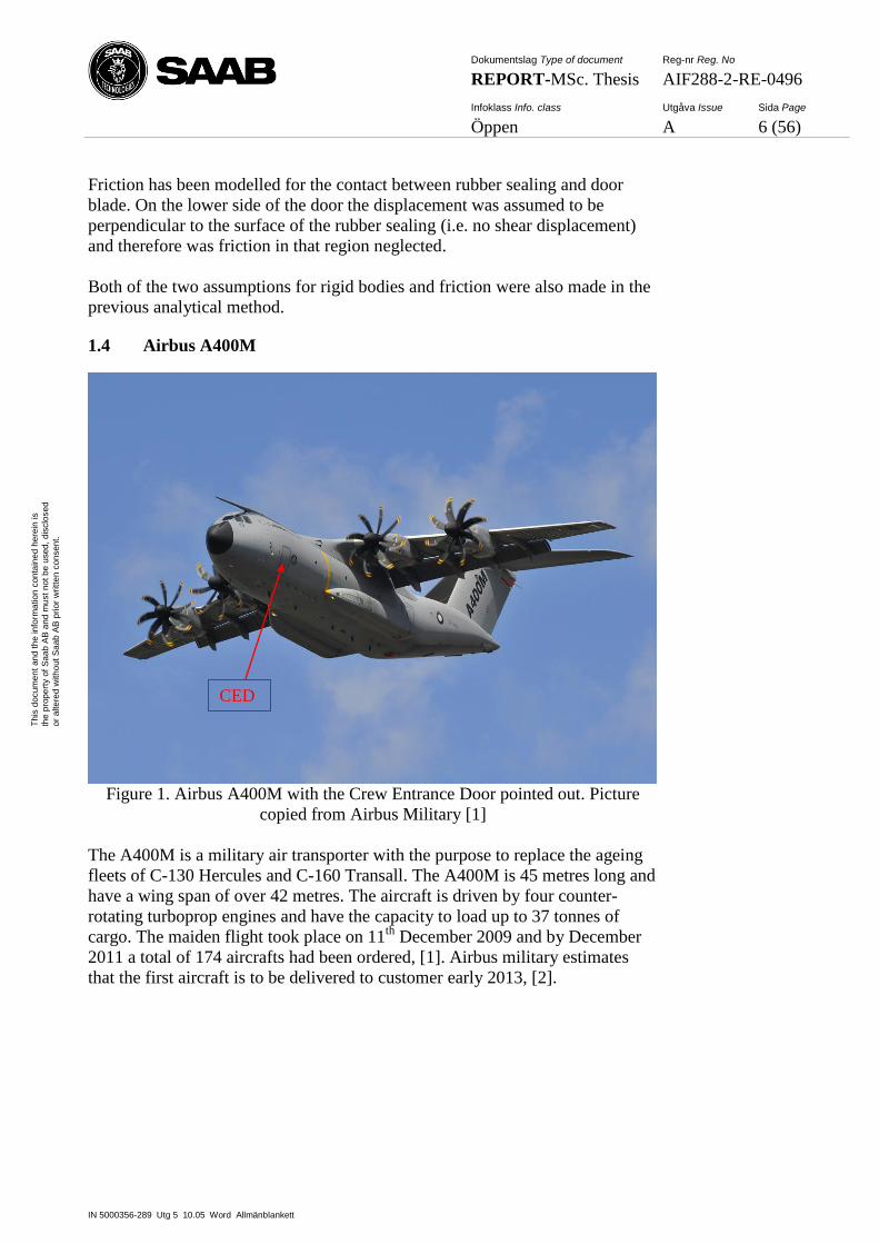
1.4 Airbus A400M
Figure 1. Airbus A400M with the Crew Entrance Door pointed out. Picture
copied from Airbus Military [1]
The A400M is a military air transporter with the purpose to replace the ageing
fleets of C-130 Hercules and C-160 Transall. The A400M is 45 metres long and
have a wing span of over 42 metres. The aircraft is driven by four counter-
rotating turboprop engines and have the capacity to load up to 37 tonnes of
cargo. The maiden flight took place on 11th
December 2009 and by December
2011 a total of 174 aircrafts had been ordered, [1]. Airbus military estimates
that the first aircraft is to be delivered to customer early 2013, [2].
CED
Dokumentslag Type of document Reg-nr Reg. No
REPORT-MSc. Thesis AIF288-2-RE-0496
Infoklass Info. class Utgåva Issue Sida Page
Öppen A 7 (56)
IN 5000356-289 Utg 5 10.05 Word Allmänblankett
Th
is d
ocum
en
t an
d t
he
in
form
atio
n c
on
tain
ed
he
rein
is
the
pro
pe
rty o
f S
aa
b A
B a
nd
mu
st
no
t b
e u
sed
, d
isclo
se
d
or
alte
red
with
ou
t S
aa
b A
B p
rior
wri
tte
n c
on
sen
t.
1.4.1 Crew Entrance Door – CED
In this subchapter the Crew Entrance Door will be presented shortly.
Figure 2. Complete CED to the left and the mechanical systems in the door to
the right
For the CED there are three positions of the door that distinguish the
manoeuvre from closed to opened door. The CED can be closed and locked,
lifted (unlocked) or opened.
Starting from closed and locked the CED should first be unlocked by lifting the
door with either the inner or outer handle, see Figure 2. These two handles lift
the door to a position where it is possible for the door to rotate outwards, called
lifted position. The door is open when it has fully rotated out to a position
where it also works as a staircase for the crew. A wire is then the only thing
keeping the door from rotating more than to opened position, see Figure 3.
Rod P2P6
Latch axis
Outer handle (hidden)
Jettison handle
Rod P7P10
Lifting rod (P11P10)
Gearbox
Picture removed in published report due to
Intellectual Property reasons
Dokumentslag Type of document Reg-nr Reg. No
REPORT-MSc. Thesis AIF288-2-RE-0496
Infoklass Info. class Utgåva Issue Sida Page
Öppen A 8 (56)
IN 5000356-289 Utg 5 10.05 Word Allmänblankett
Th
is d
ocum
en
t an
d t
he
in
form
atio
n c
on
tain
ed
he
rein
is
the
pro
pe
rty o
f S
aa
b A
B a
nd
mu
st
no
t b
e u
sed
, d
isclo
se
d
or
alte
red
with
ou
t S
aa
b A
B p
rior
wri
tte
n c
on
sen
t.
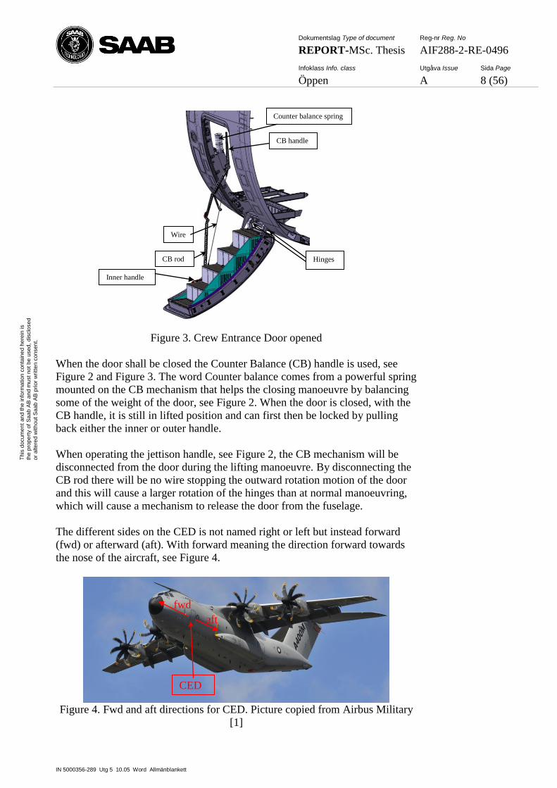
Figure 3. Crew Entrance Door opened
When the door shall be closed the Counter Balance (CB) handle is used, see
Figure 2 and Figure 3. The word Counter balance comes from a powerful spring
mounted on the CB mechanism that helps the closing manoeuvre by balancing
some of the weight of the door, see Figure 2. When the door is closed, with the
CB handle, it is still in lifted position and can first then be locked by pulling
back either the inner or outer handle.
When operating the jettison handle, see Figure 2, the CB mechanism will be
disconnected from the door during the lifting manoeuvre. By disconnecting the
CB rod there will be no wire stopping the outward rotation motion of the door
and this will cause a larger rotation of the hinges than at normal manoeuvring,
which will cause a mechanism to release the door from the fuselage.
The different sides on the CED is not named right or left but instead forward
(fwd) or afterward (aft). With forward meaning the direction forward towards
the nose of the aircraft, see Figure 4.
Figure 4. Fwd and aft directions for CED. Picture copied from Airbus Military
[1]
CED
fwd
aft
Wire
CB rod
CB handle
Hinges
Counter balance spring
Inner handle
Dokumentslag Type of document Reg-nr Reg. No
REPORT-MSc. Thesis AIF288-2-RE-0496
Infoklass Info. class Utgåva Issue Sida Page
Öppen A 9 (56)
IN 5000356-289 Utg 5 10.05 Word Allmänblankett
Th
is d
ocum
en
t an
d t
he
in
form
atio
n c
on
tain
ed
he
rein
is
the
pro
pe
rty o
f S
aa
b A
B a
nd
mu
st
no
t b
e u
sed
, d
isclo
se
d
or
alte
red
with
ou
t S
aa
b A
B p
rior
wri
tte
n c
on
sen
t.
1.5 Load Cases
Airbus decided some different load cases which the CED must be able to
withstand without the door breaking. The different load cases create reaction
forces through out the door. Time limitations has made it impossible to
compare numerical calculations (MSC Adams) with analytical calculations (MS
Excel) for all reaction forces at all locations and therefore only some reaction
forces from the different load cases will be presented and compared. The load
cases to be compared with analytical (MS Excel) calculations are the following:
1.5.1 Lifting the door
The lifting manoeuvres with either inner, outer or jettison handle were
simulated with and without an internal overpressure. The numerically
calculated forces that are compared to analytical results are handle loads and
reaction forces at Stop1 and Upper Guide, see 3.1.5.1 for more information on
Stop1 and Upper Guide.
1.5.2 Jamming during lifting manoeuvre
The lifting manoeuvres were simulated with either the inner or outer handle but
with jamming in the mechanical system, at either the gearbox, see Figure 2, or
at the outer handle, see Figure 2. A maximum allowed load was applied on the
handles and the reaction forces in two rods were calculated. In the result chapter
the reaction forces in rod P2P6 and rod P7P10, see Figure 2, are compared with
analytical calculations.
1.5.3 Opening the door
The opening manoeuvre was simulated without wind loads but also with wind
loads in both closing and opening directions. Reaction forces in hinges and CB
rod connection to the door are compared to analytical calculations.
1.5.4 Opened door
In the simulations with the CED in opened position, the external loads were
from:
One man running
Three men standing
60 knots wind load
Side load on CB arm fwd/aft direction + one man standing on step 1
Side load on CB handle fwd/aft direction
Numerically calculated reaction forces in hinges, in CB rod and reaction forces
in the wire are compared to analytical calculations.
1.5.5 Jettison manoeuvre
The jettison manoeuvre (CED falling outward) was simulated with
aerodynamic loads on the door from high speed, low altitude and high angle of
attack. Reaction forces at hinges, angular velocity and angular acceleration for
the door during jettison are compared with analytical calculations.
Dokumentslag Type of document Reg-nr Reg. No
REPORT-MSc. Thesis AIF288-2-RE-0496
Infoklass Info. class Utgåva Issue Sida Page
Öppen A 10 (56)
IN 5000356-289 Utg 5 10.05 Word Allmänblankett
Th
is d
ocum
en
t an
d t
he
in
form
atio
n c
on
tain
ed
he
rein
is
the
pro
pe
rty o
f S
aa
b A
B a
nd
mu
st
no
t b
e u
sed
, d
isclo
se
d
or
alte
red
with
ou
t S
aa
b A
B p
rior
wri
tte
n c
on
sen
t.
2 THEORY - MULTIBODY SYSTEMS
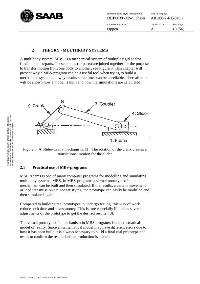
A multibody system, MBS, is a mechanical system of multiple rigid and/or
flexible bodies/parts. These bodies (or parts) are joined together for the purpose
to transfer motion from one body to another, see Figure 5. This chapter will
present why a MBS-program can be a useful tool when trying to build a
mechanical system and why results sometimes can be unreliable. Thereafter, it
will be shown how a model is built and how the simulations are calculated.
Figure 5. A Slider-Crank mechanism, [3]. The rotation of the crank creates a
translational motion for the slider
2.1 Practical use of MBS-programs
MSC Adams is one of many computer programs for modelling and simulating
multibody systems, MBS. In MBS-programs a virtual prototype of a
mechanism can be built and then simulated. If the results, a certain movement
or load transmission are not satisfying, the prototype can easily be modified and
then simulated again.
Compared to building real prototypes to undergo testing, this way of work
reduce both time and saves money. This is true especially if it takes several
adjustments of the prototype to get the desired results, [3].
The virtual prototype of a mechanism in MBS programs is a mathematical
model of reality. Since a mathematical model may have different errors due to
how it has been built, it is always necessary to build a final real prototype and
test it to confirm the results before production is started.
Dokumentslag Type of document Reg-nr Reg. No
REPORT-MSc. Thesis AIF288-2-RE-0496
Infoklass Info. class Utgåva Issue Sida Page
Öppen A 11 (56)
IN 5000356-289 Utg 5 10.05 Word Allmänblankett
Th
is d
ocum
en
t an
d t
he
in
form
atio
n c
on
tain
ed
he
rein
is
the
pro
pe
rty o
f S
aa
b A
B a
nd
mu
st
no
t b
e u
sed
, d
isclo
se
d
or
alte
red
with
ou
t S
aa
b A
B p
rior
wri
tte
n c
on
sen
t.
Errors that can occur in MBS models:
In a model built with rigid bodies the loads in the system are
assumed to be so small that it will not introduce neither elastic nor
plastic deformation. If the forces applied in the system would in reality
give large deformation, the calculated result would differ substantially
compared to physical testing, [3].
A model should not be modelled more complex than necessary for
a correct presentation of the system. However if a model is built too
simple it may mean that some things that has influence on the motion of
the system is not modelled and therefore differs the result compared to
physical testing, [3].
Bad input makes the model a bad approximation of reality. Such
inputs could be friction coefficients or stiffness and damping values for
springs, [3]. In addition, incorrect geometry may produce big
differences in mass and inertia compared to reality.
A rigid body system should not be modelled with redundant
constraints, even if the real mechanical system is such. Redundant
constraints can cause high reaction forces that have nothing to do with
reality, see 3.1.4.
When solving differential equations, numerical errors could lead
to a solution greatly different from the real solution, [3].
2.2 Build a model
In this subchapter it is described how a model is built by joining parts.
In a mechanical system parts can be connected with something called joints.
These joints determine how one part is allowed to move relative to another part.
Every joints function is to decrease the mobility for a set of parts and this is
done by locking so called degrees of freedom, DOF.
A part has initially 6 DOF, three axis directions or any combined direction to
translate in and also rotation around those three axes or any combined direction.
When parts are joined together, some of the DOF’s are locked.
Joints can be divided into two groups; lower and higher pairs. A lower pair is a
joint with an area contact between the two bodies. A higher pair is instead a
joint with only a point or a line contact, [3].
Dokumentslag Type of document Reg-nr Reg. No
REPORT-MSc. Thesis AIF288-2-RE-0496
Infoklass Info. class Utgåva Issue Sida Page
Öppen A 12 (56)
IN 5000356-289 Utg 5 10.05 Word Allmänblankett
Th
is d
ocum
en
t an
d t
he
in
form
atio
n c
on
tain
ed
he
rein
is
the
pro
pe
rty o
f S
aa
b A
B a
nd
mu
st
no
t b
e u
sed
, d
isclo
se
d
or
alte
red
with
ou
t S
aa
b A
B p
rior
wri
tte
n c
on
sen
t.
2.2.1 Lower pairs
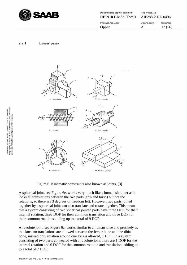
Figure 6. Kinematic constraints also known as joints, [3]
A spherical joint, see Figure 6e, works very much like a human shoulder as it
locks all translations between the two parts (arm and torso) but not the
rotations, so there are 3 degrees of freedom left. However, two parts joined
together by a spherical joint can also translate and rotate together. This means
that a system consisting of two spherical jointed parts have three DOF for their
internal rotation, three DOF for their common translation and three DOF for
their common rotations adding up to a total of 9 DOF.
A revolute joint, see Figure 6a, works similar to a human knee and precisely as
in a knee no translations are allowed between the femur bone and the tibia
bone, instead only rotation around one axis is allowed, 1 DOF. In a system
consisting of two parts connected with a revolute joint there are 1 DOF for the
internal rotation and 6 DOF for the common rotation and translation, adding up
to a total of 7 DOF.
Dokumentslag Type of document Reg-nr Reg. No
REPORT-MSc. Thesis AIF288-2-RE-0496
Infoklass Info. class Utgåva Issue Sida Page
Öppen A 13 (56)
IN 5000356-289 Utg 5 10.05 Word Allmänblankett
Th
is d
ocum
en
t an
d t
he
in
form
atio
n c
on
tain
ed
he
rein
is
the
pro
pe
rty o
f S
aa
b A
B a
nd
mu
st
no
t b
e u
sed
, d
isclo
se
d
or
alte
red
with
ou
t S
aa
b A
B p
rior
wri
tte
n c
on
sen
t.
A cylindrical joint, see Figure 6d, is similar to a revolute joint but with the
difference that a cylindrical joint also allows translation in direction of the
rotational axis. Consequently 1 DOF is released between two bodies connected
with a cylindrical joint compared to two bodies connected with a revolute joint.
A translational/prismatic joint, see Figure 6b, only allows translation in one
direction and allows no rotations at all. A planar joint, see Figure 6f, restrict the
two parts so that they must always lie in the same plane. A planar joint can be
described as the limitations for a computer mouse to the mouse pad. The
computer mouse can be rotated around an axis normal to the desktop and it can
also be moved forward/backward and to the sides but are not allowed to lift
from the mouse pad.
The sixth joint is the screw joint, see Figure 6c, it works like a cylindrical joint
but with the rotation as a function of translation and has therefore one less
degree of freedom.
Finally there is an additional joint called a fix joint which locks all 6 degrees of
freedom between two bodies.
2.2.2 Higher pairs
In addition to the lower pairs there are a few more joints called higher pairs.
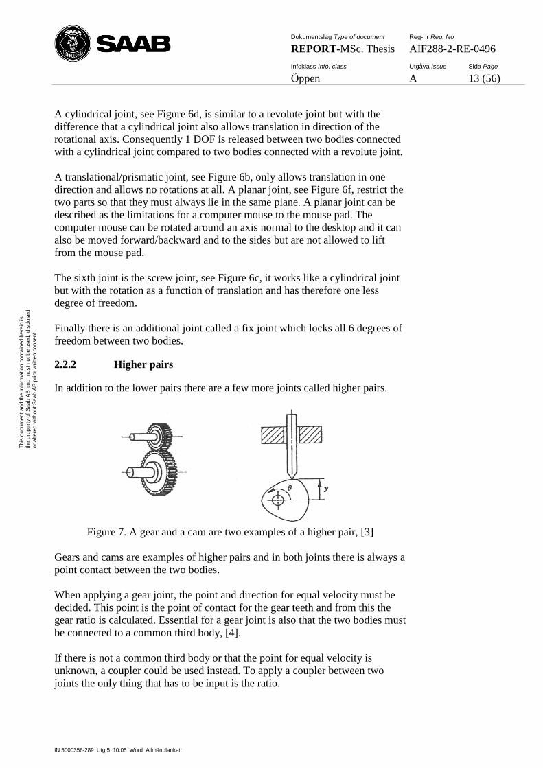
Figure 7. A gear and a cam are two examples of a higher pair, [3]
Gears and cams are examples of higher pairs and in both joints there is always a
point contact between the two bodies.
When applying a gear joint, the point and direction for equal velocity must be
decided. This point is the point of contact for the gear teeth and from this the
gear ratio is calculated. Essential for a gear joint is also that the two bodies must
be connected to a common third body, [4].
If there is not a common third body or that the point for equal velocity is
unknown, a coupler could be used instead. To apply a coupler between two
joints the only thing that has to be input is the ratio.
Dokumentslag Type of document Reg-nr Reg. No
REPORT-MSc. Thesis AIF288-2-RE-0496
Infoklass Info. class Utgåva Issue Sida Page
Öppen A 14 (56)
IN 5000356-289 Utg 5 10.05 Word Allmänblankett
Th
is d
ocum
en
t an
d t
he
in
form
atio
n c
on
tain
ed
he
rein
is
the
pro
pe
rty o
f S
aa
b A
B a
nd
mu
st
no
t b
e u
sed
, d
isclo
se
d
or
alte
red
with
ou
t S
aa
b A
B p
rior
wri
tte
n c
on
sen
t.
2.2.3 Driving constraints
If a joint allows rotation or translation then it is possible to apply a motion to
that joint. This motion is called a driving constraint and it can be a function of
an independent parameter, for example time. When applying a motion the DOF
corresponding to that motion are locked.
2.2.4 Forces
In addition to joints and motions also forces can be applied between parts. A
force can be constant or a function of an independent parameter (such as time)
and it can also for example be programmed so it will act as a spring with or
without damping between two parts.
2.2.5 The Contact Function
Bodies in MSC Adams do not by default notice a collision during simulation.
One body will move into another as if there were made out of thin air. If it is
desired to simulate a collision, then a Contact function could be applied on the
specific parts.
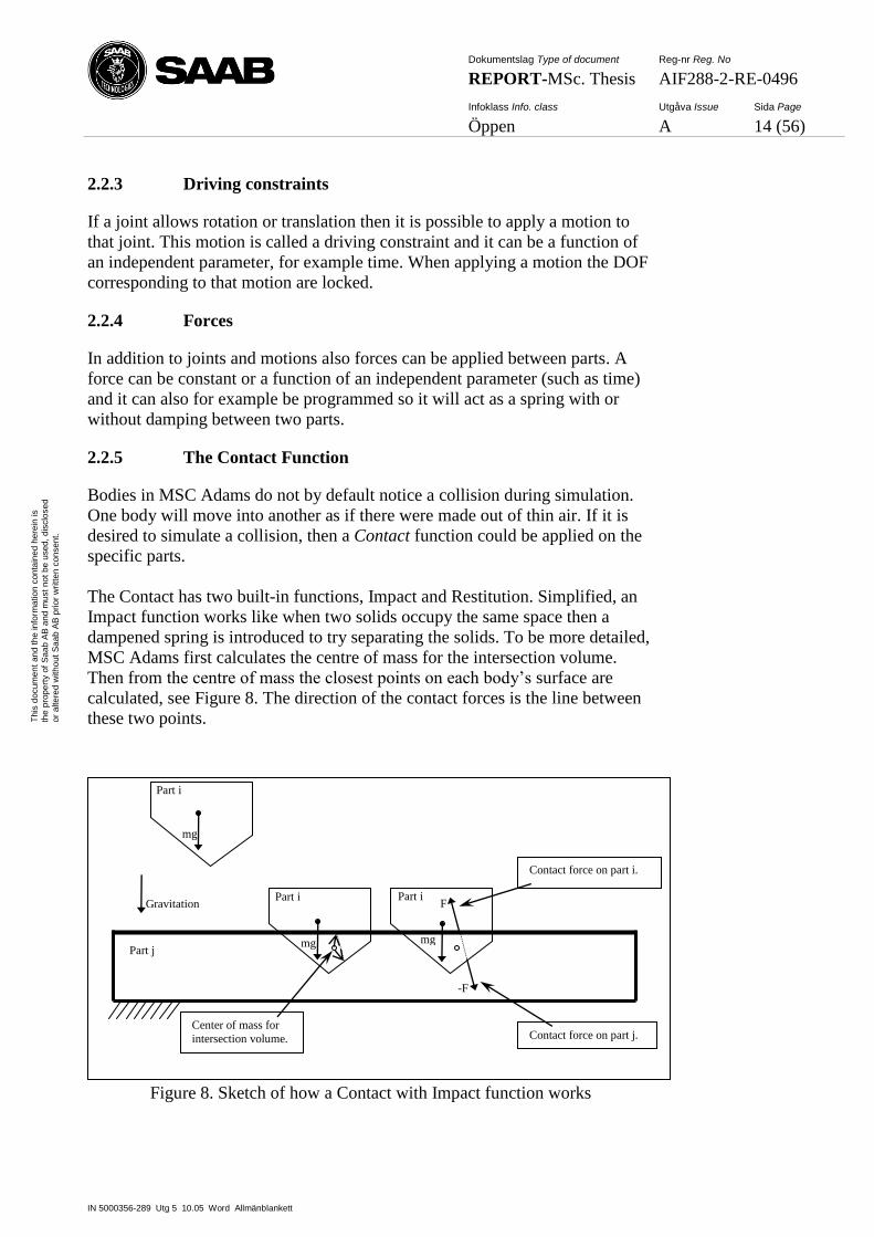
The Contact has two built-in functions, Impact and Restitution. Simplified, an
Impact function works like when two solids occupy the same space then a
dampened spring is introduced to try separating the solids. To be more detailed,
MSC Adams first calculates the centre of mass for the intersection volume.
Then from the centre of mass the closest points on each body’s surface are
calculated, see Figure 8. The direction of the contact forces is the line between
these two points.
Figure 8. Sketch of how a Contact with Impact function works
Gravitation
Contact force on part i.
Contact force on part j.
mg
Center of mass for
intersection volume.
Part i
mg
Part i
mg
Part i
Part j
F
-F
Dokumentslag Type of document Reg-nr Reg. No
REPORT-MSc. Thesis AIF288-2-RE-0496
Infoklass Info. class Utgåva Issue Sida Page
Öppen A 15 (56)
IN 5000356-289 Utg 5 10.05 Word Allmänblankett
Th
is d
ocum
en
t an
d t
he
in
form
atio
n c
on
tain
ed
he
rein
is
the
pro
pe
rty o
f S
aa
b A
B a
nd
mu
st
no
t b
e u
sed
, d
isclo
se
d
or
alte
red
with
ou
t S
aa
b A
B p
rior
wri
tte
n c
on
sen
t.
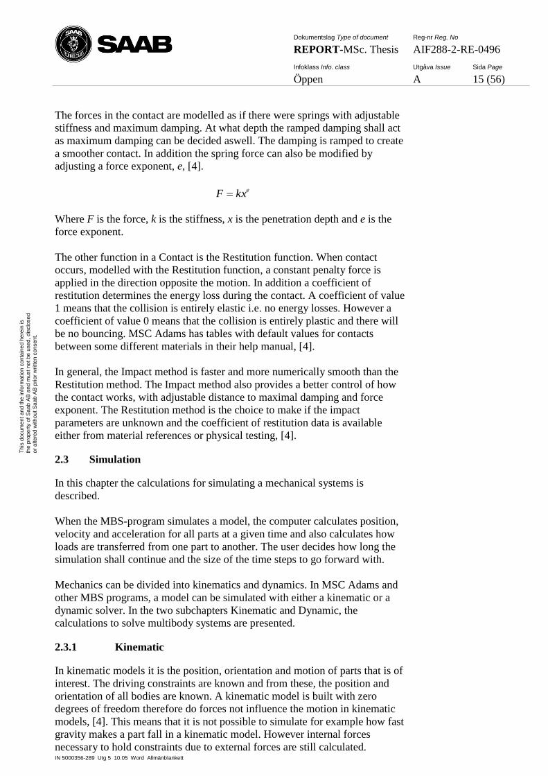
The forces in the contact are modelled as if there were springs with adjustable
stiffness and maximum damping. At what depth the ramped damping shall act
as maximum damping can be decided aswell. The damping is ramped to create
a smoother contact. In addition the spring force can also be modified by
adjusting a force exponent, e, [4].
ekxF
Where F is the force, k is the stiffness, x is the penetration depth and e is the
force exponent.
The other function in a Contact is the Restitution function. When contact
occurs, modelled with the Restitution function, a constant penalty force is
applied in the direction opposite the motion. In addition a coefficient of
restitution determines the energy loss during the contact. A coefficient of value
1 means that the collision is entirely elastic i.e. no energy losses. However a
coefficient of value 0 means that the collision is entirely plastic and there will
be no bouncing. MSC Adams has tables with default values for contacts
between some different materials in their help manual, [4].
In general, the Impact method is faster and more numerically smooth than the
Restitution method. The Impact method also provides a better control of how
the contact works, with adjustable distance to maximal damping and force
exponent. The Restitution method is the choice to make if the impact
parameters are unknown and the coefficient of restitution data is available
either from material references or physical testing, [4].
2.3 Simulation
In this chapter the calculations for simulating a mechanical systems is
described.
When the MBS-program simulates a model, the computer calculates position,
velocity and acceleration for all parts at a given time and also calculates how
loads are transferred from one part to another. The user decides how long the
simulation shall continue and the size of the time steps to go forward with.
Mechanics can be divided into kinematics and dynamics. In MSC Adams and
other MBS programs, a model can be simulated with either a kinematic or a
dynamic solver. In the two subchapters Kinematic and Dynamic, the
calculations to solve multibody systems are presented.
2.3.1 Kinematic
In kinematic models it is the position, orientation and motion of parts that is of
interest. The driving constraints are known and from these, the position and
orientation of all bodies are known. A kinematic model is built with zero
degrees of freedom therefore do forces not influence the motion in kinematic
models, [4]. This means that it is not possible to simulate for example how fast
gravity makes a part fall in a kinematic model. However internal forces
necessary to hold constraints due to external forces are still calculated.
Dokumentslag Type of document Reg-nr Reg. No
REPORT-MSc. Thesis AIF288-2-RE-0496
Infoklass Info. class Utgåva Issue Sida Page
Öppen A 16 (56)
IN 5000356-289 Utg 5 10.05 Word Allmänblankett
Th
is d
ocum
en
t an
d t
he
in
form
atio
n c
on
tain
ed
he
rein
is
the
pro
pe
rty o
f S
aa
b A
B a
nd
mu
st
no
t b
e u
sed
, d
isclo
se
d
or
alte
red
with
ou
t S
aa
b A
B p
rior
wri
tte
n c
on
sen
t.
All equations in this chapter are referred to an unpublished course material for
University of Linkoping written by Christensen, Peter [3] unless otherwise
explicitly stated.
Let q be a matrix containing positions for all parts in the system, i.e. x, y and z
coordinates and the angle of rotation around those axes. Hk(q) is a matrix
consisting of all kinematic constraints due to the joints connecting parts, for
example a revolute joint.
T
nbnbnbnbnbnb111111 ,,z,y,x,,,,z,y,[x q
0qHqHqHqHqH T
nk321 )(,),(),(),()( kkkkk
In a multibody system it is possible to apply a motion to a joint, a driving
constraint Hd(q,t). H
d can aside from position also be a function of time, [3].
0qHqHqHqHqH T
nk321 ),(,),,(),,(),,(),( ttttt ddddd
Together, the kinematic constraints, Hk, and the driving constraints, H
d, creates
the matrix H.
0qH
qHqH
),(
)(),(
tt
d
k
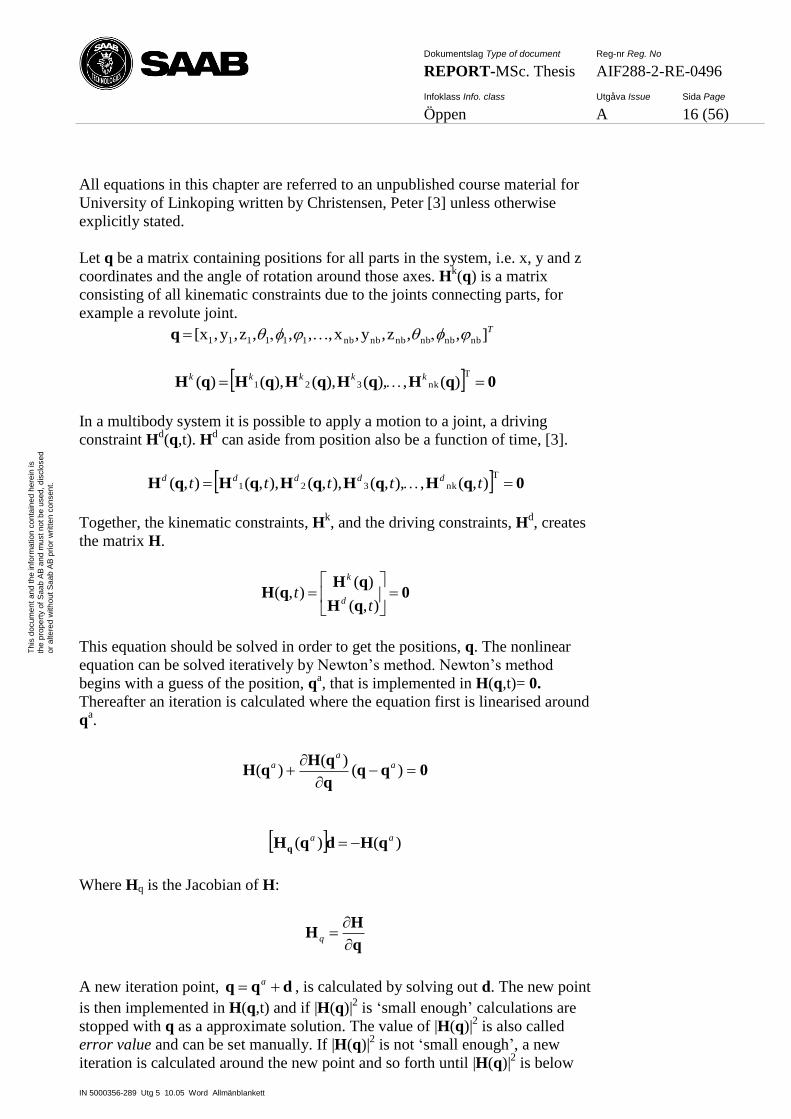
This equation should be solved in order to get the positions, q. The nonlinear
equation can be solved iteratively by Newton’s method. Newton’s method
begins with a guess of the position, qa, that is implemented in H(q,t)= 0.
Thereafter an iteration is calculated where the equation first is linearised around
qa.
0qqq
qHqH
)(
)()( a
aa
)()( aaqHdqHq
Where Hq is the Jacobian of H:
q
HH
q
A new iteration point, dqq a , is calculated by solving out d. The new point
is then implemented in H(q,t) and if |H(q)|2 is ‘small enough’ calculations are
stopped with q as a approximate solution. The value of |H(q)|2 is also called
error value and can be set manually. If |H(q)|2 is not ‘small enough’, a new
iteration is calculated around the new point and so forth until |H(q)|2 is below
Dokumentslag Type of document Reg-nr Reg. No
REPORT-MSc. Thesis AIF288-2-RE-0496
Infoklass Info. class Utgåva Issue Sida Page
Öppen A 17 (56)
IN 5000356-289 Utg 5 10.05 Word Allmänblankett
Th
is d
ocum
en
t an
d t
he
in
form
atio
n c
on
tain
ed
he
rein
is
the
pro
pe
rty o
f S
aa
b A
B a
nd
mu
st
no
t b
e u
sed
, d
isclo
se
d
or
alte
red
with
ou
t S
aa
b A
B p
rior
wri
tte
n c
on
sen
t.
the error value. Thereafter the procedure is done again for every time step in
the simulation.
The size or number of time steps is decided by the user. The appropriate size of
the time steps is depending on how much the parts are moving in the system. If
the parts have high acceleration and moves rapidly then shorter time steps
might be necessary to get a satisfying value of |H(q)|2. However if the size of
the time steps are too small it can also give a long simulation time.
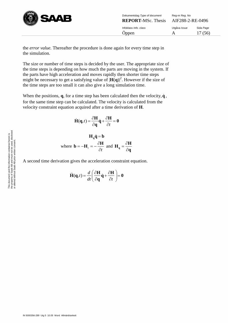
When the positions, q, for a time step has been calculated then the velocity, q ,
for the same time step can be calculated. The velocity is calculated from the
velocity constraint equation acquired after a time derivation of H.
0H
HqH
tt ),(
bqHq
where t
t
HHb and
q
HHq
A second time derivation gives the acceleration constraint equation.
0H
HqH
tdt
dt ),(
Dokumentslag Type of document Reg-nr Reg. No
REPORT-MSc. Thesis AIF288-2-RE-0496
Infoklass Info. class Utgåva Issue Sida Page
Öppen A 18 (56)
IN 5000356-289 Utg 5 10.05 Word Allmänblankett
Th
is d
ocum
en
t an
d t
he
in
form
atio
n c
on
tain
ed
he
rein
is
the
pro
pe
rty o
f S
aa
b A
B a
nd
mu
st
no
t b
e u
sed
, d
isclo
se
d
or
alte
red
with
ou
t S
aa
b A
B p
rior
wri
tte
n c
on
sen
t.
Which gives:
cqHq
where ttt HqHqqHc qqq 2)( and 2
2
ttt
HH ;
tt
q
HHq
2
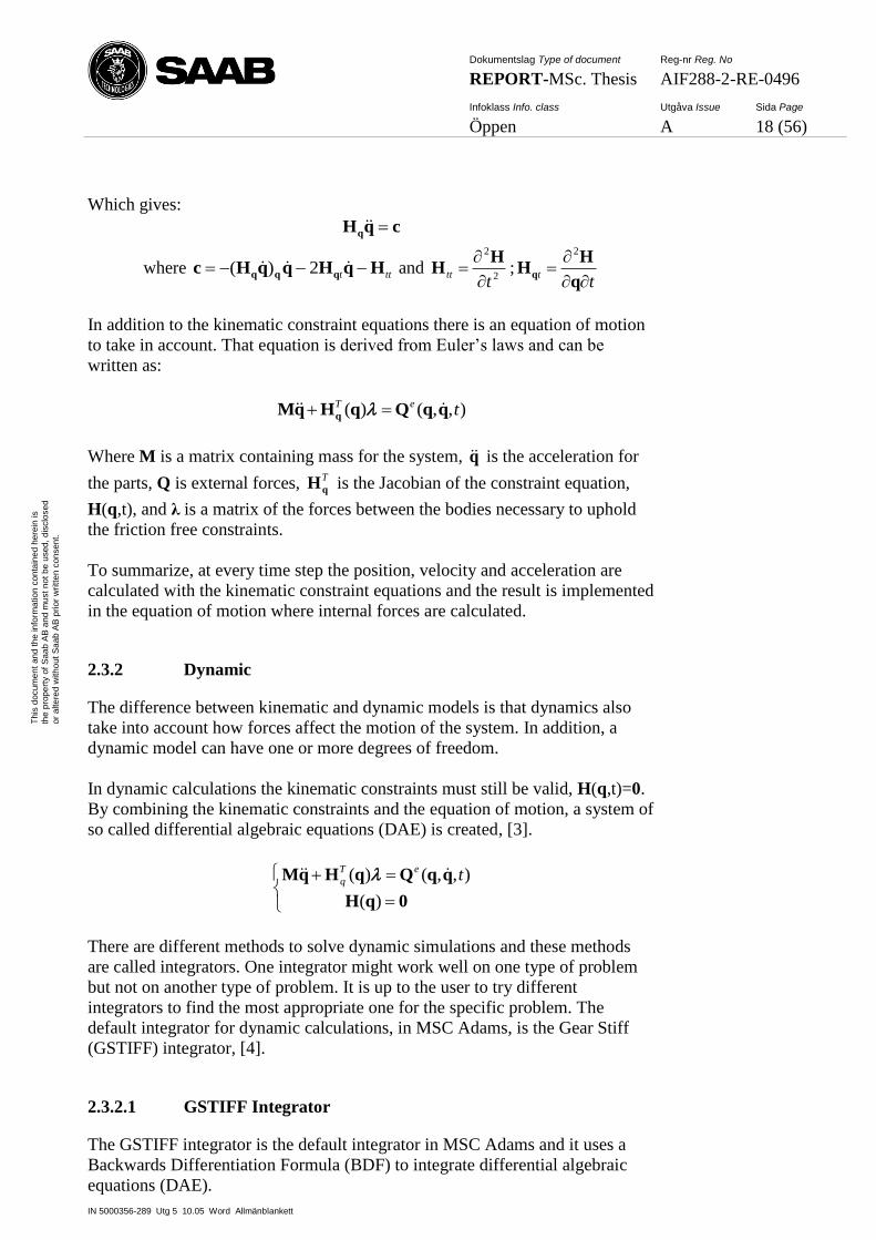
In addition to the kinematic constraint equations there is an equation of motion
to take in account. That equation is derived from Euler’s laws and can be
written as:
),,()( teTqqQqHqM q
Where M is a matrix containing mass for the system, q is the acceleration for
the parts, Q is external forces, T
qH is the Jacobian of the constraint equation,
H(q,t), and λ is a matrix of the forces between the bodies necessary to uphold
the friction free constraints.
To summarize, at every time step the position, velocity and acceleration are
calculated with the kinematic constraint equations and the result is implemented
in the equation of motion where internal forces are calculated.
2.3.2 Dynamic
The difference between kinematic and dynamic models is that dynamics also
take into account how forces affect the motion of the system. In addition, a
dynamic model can have one or more degrees of freedom.
In dynamic calculations the kinematic constraints must still be valid, H(q,t)=0.
By combining the kinematic constraints and the equation of motion, a system of
so called differential algebraic equations (DAE) is created, [3].
0qH
qqQqHqM
)(
),,()( teT
q
There are different methods to solve dynamic simulations and these methods
are called integrators. One integrator might work well on one type of problem
but not on another type of problem. It is up to the user to try different
integrators to find the most appropriate one for the specific problem. The
default integrator for dynamic calculations, in MSC Adams, is the Gear Stiff
(GSTIFF) integrator, [4].
2.3.2.1 GSTIFF Integrator
The GSTIFF integrator is the default integrator in MSC Adams and it uses a
Backwards Differentiation Formula (BDF) to integrate differential algebraic
equations (DAE).
Dokumentslag Type of document Reg-nr Reg. No
REPORT-MSc. Thesis AIF288-2-RE-0496
Infoklass Info. class Utgåva Issue Sida Page
Öppen A 19 (56)
IN 5000356-289 Utg 5 10.05 Word Allmänblankett
Th
is d
ocum
en
t an
d t
he
in
form
atio
n c
on
tain
ed
he
rein
is
the
pro
pe
rty o
f S
aa
b A
B a
nd
mu
st
no
t b
e u
sed
, d
isclo
se
d
or
alte
red
with
ou
t S
aa
b A
B p
rior
wri
tte
n c
on
sen
t.
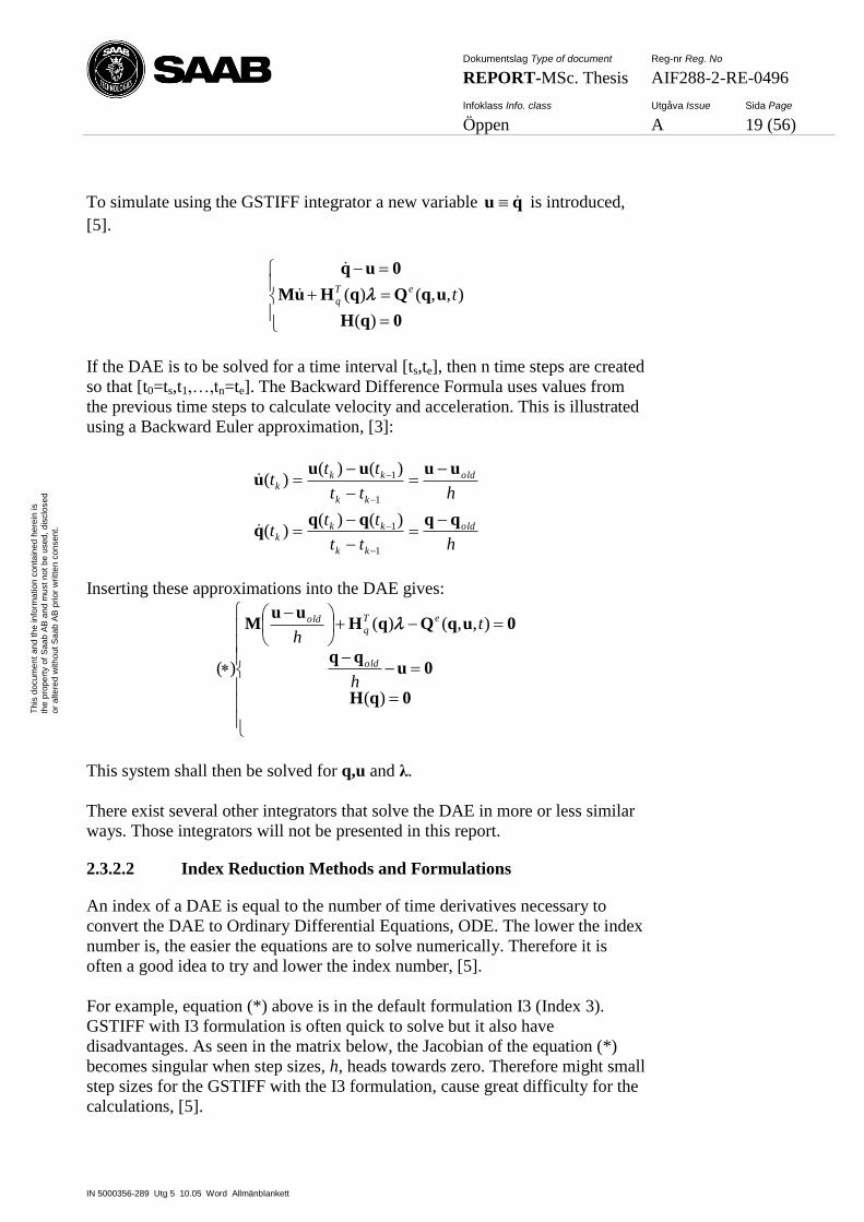
To simulate using the GSTIFF integrator a new variable qu is introduced,
[5].
0qH
uqQqHuM
0uq
)(
),,()( teT
q
If the DAE is to be solved for a time interval [ts,te], then n time steps are created
so that [t0=ts,t1,…,tn=te]. The Backward Difference Formula uses values from
the previous time steps to calculate velocity and acceleration. This is illustrated
using a Backward Euler approximation, [3]:
htt
ttt
htt
ttt
old
kk
kkk
old
kk
kkk
qqqqq
uuuuu
1
1
1
1
)()()(
)()()(
Inserting these approximations into the DAE gives:
0qH
0uqq
0uqQqHuu
M
)(
),,()(
)(h
th
old
eT
qold
This system shall then be solved for q,u and λ.
There exist several other integrators that solve the DAE in more or less similar
ways. Those integrators will not be presented in this report.
2.3.2.2 Index Reduction Methods and Formulations
An index of a DAE is equal to the number of time derivatives necessary to
convert the DAE to Ordinary Differential Equations, ODE. The lower the index
number is, the easier the equations are to solve numerically. Therefore it is
often a good idea to try and lower the index number, [5].
For example, equation (*) above is in the default formulation I3 (Index 3).
GSTIFF with I3 formulation is often quick to solve but it also have
disadvantages. As seen in the matrix below, the Jacobian of the equation (*)
becomes singular when step sizes, h, heads towards zero. Therefore might small
step sizes for the GSTIFF with the I3 formulation, cause great difficulty for the
calculations, [5].

Dokumentslag Type of document Reg-nr Reg. No
REPORT-MSc. Thesis AIF288-2-RE-0496
Infoklass Info. class Utgåva Issue Sida Page
Öppen A 20 (56)
IN 5000356-289 Utg 5 10.05 Word Allmänblankett
Th
is d
ocum
en
t an
d t
he
in
form
atio
n c
on
tain
ed
he
rein
is
the
pro
pe
rty o
f S
aa
b A
B a
nd
mu
st
no
t b
e u
sed
, d
isclo
se
d
or
alte
red
with
ou
t S
aa
b A
B p
rior
wri
tte
n c
on
sen
t.
q
u
x0xG ;)(
0H0
0II
HQHQM
x
G
q
qqqqu
h
h
TeTe
1
1
To lower the risk of a singular Jacobian an index reduction method (IRM) can
be used. The IRM is based on exchanging some of the equations in the DAE
with time derivatives of the same equations. For example, the kinematic
constraint equation can be replaced with the time derivative of the same
kinematic constraint equation.
0qH
0uqq
0uqQqHuu
M
)(
)()(
),,()()()(
(**)1
1
1
1
kk
kk
eT
q
kk
kk
tt
tt
ttt
tt
By using equation (**) above instead of equation (*), the Jacobian does not
become singular with small step sizes, [5].
However this also means that the original kinematic constraint does not need to
be fulfilled. So instead of having a kinematic equation saying that the distance
between parts in a joint must be zero now instead an equation is used where the
velocity between parts in a joint shall be zero. A complication due to this
modification can be that parts in the model might slowly drift away after some
simulation time, a so called drift-off, [5].
In MCS Adams there are a few different formulations to choose of when
simulating a model. If there is drift-off issues then the default I3 formulation
can be replaced by the SI2 (stabilized index 2) formulation.
In SI2, some modifications are introduced:
0qH
0uqH
0qHqu
0uqQqHuM
),(
),,(
)(
),,()(
t
t
tT
q
eT
q
Using the SI2 formulation, both the velocity and position equations are fulfilled
giving a non-singular Jacobian and preventing drift-off.

Dokumentslag Type of document Reg-nr Reg. No
REPORT-MSc. Thesis AIF288-2-RE-0496
Infoklass Info. class Utgåva Issue Sida Page
Öppen A 21 (56)
IN 5000356-289 Utg 5 10.05 Word Allmänblankett
Th
is d
ocum
en
t an
d t
he
in
form
atio
n c
on
tain
ed
he
rein
is
the
pro
pe
rty o
f S
aa
b A
B a
nd
mu
st
no
t b
e u
sed
, d
isclo
se
d
or
alte
red
with
ou
t S
aa
b A
B p
rior
wri
tte
n c
on
sen
t.
Running GSTIFF with SI2 is 25%-100% slower than GSTIFF with I3
formulation at the same error value. However the SI2 formulation usually
allows a 10 to a 100 times larger error value than I3 to produce result with the
same accuracy and can therefore be simulated with larger time steps, [5].
There exist several other formulations for DAE and those will not be presented
in this report.
Dokumentslag Type of document Reg-nr Reg. No
REPORT-MSc. Thesis AIF288-2-RE-0496
Infoklass Info. class Utgåva Issue Sida Page
Öppen A 22 (56)
IN 5000356-289 Utg 5 10.05 Word Allmänblankett
Th
is d
ocum
en
t an
d t
he
in
form
atio
n c
on
tain
ed
he
rein
is
the
pro
pe
rty o
f S
aa
b A
B a
nd
mu
st
no
t b
e u
sed
, d
isclo
se
d
or
alte
red
with
ou
t S
aa
b A
B p
rior
wri
tte
n c
on
sen
t.
3 METHOD
This chapter with subchapters describes the method in how the MSC Adams
model was built.
3.1 Building the model
The numerical model of the CED was built in MSC Adams as a dynamic model
with forces affecting the motions of the bodies. However the analytical
calculations done in MS Excel were on a kinematic model of the CED. The
reason why modelling the CED as a dynamic model, was to easily be able to
calculate the velocity and acceleration of rotation for the hinges during jettison.
By simulating the other cases with a slow and constant motion of the bodies,
the dynamic calculations were assumed to be similar to the kinematic
calculations.
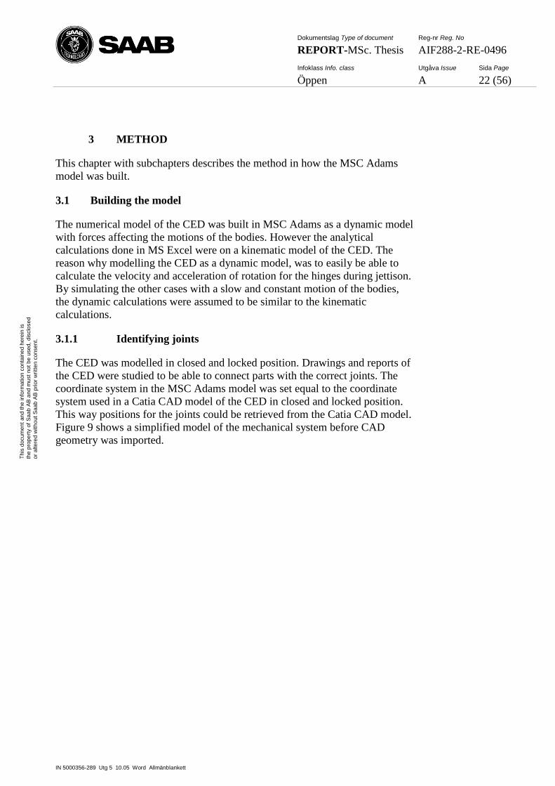
3.1.1 Identifying joints
The CED was modelled in closed and locked position. Drawings and reports of
the CED were studied to be able to connect parts with the correct joints. The
coordinate system in the MSC Adams model was set equal to the coordinate
system used in a Catia CAD model of the CED in closed and locked position.
This way positions for the joints could be retrieved from the Catia CAD model.
Figure 9 shows a simplified model of the mechanical system before CAD
geometry was imported.
Dokumentslag Type of document Reg-nr Reg. No
REPORT-MSc. Thesis AIF288-2-RE-0496
Infoklass Info. class Utgåva Issue Sida Page
Öppen A 23 (56)
IN 5000356-289 Utg 5 10.05 Word Allmänblankett
Th
is d
ocum
en
t an
d t
he
in
form
atio
n c
on
tain
ed
he
rein
is
the
pro
pe
rty o
f S
aa
b A
B a
nd
mu
st
no
t b
e u
sed
, d
isclo
se
d
or
alte
red
with
ou
t S
aa
b A
B p
rior
wri
tte
n c
on
sen
t.
Figure 9. Simplified model of the mechanical system before CAD geometry
was imported. The red cylinder is the shaft on which the inner handle is
mounted on and the yellow cylinder is the shaft on which the outer handle is
mounted on
3.1.2 Importing CAD geometry
In order to get more accurate mass properties of the parts in the model and to
make the model look as the Saab engineers are used to see it, CAD geometry
was imported to the model.
For the CED there already existed parts modeled in Catia. Assemblies of these
parts could be saved as Step-files (*.stp/*.step) that could be import directly
into MSC Adams. However, directly importing Step-files was not
recommended by MSC since the result often were some parts not being
imported as massive solids but as mass-less sheet-bodies instead. The reason
why geometry turns into sheet-bodies instead of solids was that MSC Adams
finds a hole or holes in the geometry and could therefore not make it a solid.
If the geometry was imported with the only purpose to be visual then some
parts being sheet-bodies would not have made a difference. However, importing
geometry as solids has advantages. If density was applied to an imported solid
part then MSC Adams could automatically calculate mass, centre of mass and
inertia for that part.
Dokumentslag Type of document Reg-nr Reg. No
REPORT-MSc. Thesis AIF288-2-RE-0496
Infoklass Info. class Utgåva Issue Sida Page
Öppen A 24 (56)
IN 5000356-289 Utg 5 10.05 Word Allmänblankett
Th
is d
ocum
en
t an
d t
he
in
form
atio
n c
on
tain
ed
he
rein
is
the
pro
pe
rty o
f S
aa
b A
B a
nd
mu
st
no
t b
e u
sed
, d
isclo
se
d
or
alte
red
with
ou
t S
aa
b A
B p
rior
wri
tte
n c
on
sen
t.
To increase the chances of receiving solids when importing geometry, the Step
files from Catia were converted into MSC Adams preferred file format
Parasolid (*.xmt_txt). With the CAD geometry in the file format Parasolid then
the majority of the parts could be imported as solids. However the conversion
from Step to Parasolid file format was done by third-party computer software.
In this work the computer software Rhinoceros Inc [6] was used to convert Step
files into Parasolid files. The mass for the parts still being imported as sheet-
bodies were added to a nearby solid. In Figure 10 the entire mechanical system
are shown with geometry from Catia.
Figure 10. The mechanical system with CAD parts from Catia. In this figure the
parts not belonging to the mechanical system has been made partly transparent
3.1.3 Accurate mass
In order to get the MSC Adams model to have accurate mass, one important
thing was to import CAD parts for which MSC Adams calculated centre of
mass and inertia. Mass for the parts in the mechanical system and the total mass
for the door were set manually according to a CED mass data report, [10]. For
the mechanical system attached to the fuselage (CB and jettison mechanisms)
their mass was set to what MSC Adams automatically calculated when the parts
were given a density.
The mass for the parts on the CED that did not belong to the mechanical system
were added together to the door blade. The mass and the centre of mass were
adjusted so the total mass and combined centre of mass for the door
corresponded with CED mass data report, [10].
Picture removed in
published report due to
Intellectual Property
reasons
Dokumentslag Type of document Reg-nr Reg. No
REPORT-MSc. Thesis AIF288-2-RE-0496
Infoklass Info. class Utgåva Issue Sida Page
Öppen A 25 (56)
IN 5000356-289 Utg 5 10.05 Word Allmänblankett
Th
is d
ocum
en
t an
d t
he
in
form
atio
n c
on
tain
ed
he
rein
is
the
pro
pe
rty o
f S
aa
b A
B a
nd
mu
st
no
t b
e u
sed
, d
isclo
se
d
or
alte
red
with
ou
t S
aa
b A
B p
rior
wri
tte
n c
on
sen
t.
3.1.4 Redundant constraints
It is important to be careful when building a mechanical model. It is very easy
by accident to lock a degree of freedom that is already locked by another joint.
When this has happened the system is said to be over-constrained and the
constraints causing it is called redundant constraints. An example of this could
be a normal kitchen cabinet door. The door has two hinges and both constrain
the door so it can not translate in any direction and only rotate around hinge
line. This door is over-constrained since it basically would only require one
hinge to restrain the door in that way.
However this is not a problem for the kitchen cabinet door since if there were a
small misalignment in the hinges there would just be a small deformation at one
or both of the hinges that would correct the misalignment. In rigid body
mechanics however there exists no deformation so in the model of the same
kitchen cabinet door there would instead be large forces between the hinges due
to the misalignment. These loads have nothing to do with reality and therefore
should over-constrained systems not be accepted in a rigid body model.
Fortunately there is a function in MSC Adams that, if the system is over-
constrained, can calculate which joints are unnecessarily locking degrees of
freedom. However it does not have to be that particular joint that is wrong. The
function only states which joints are redundant.
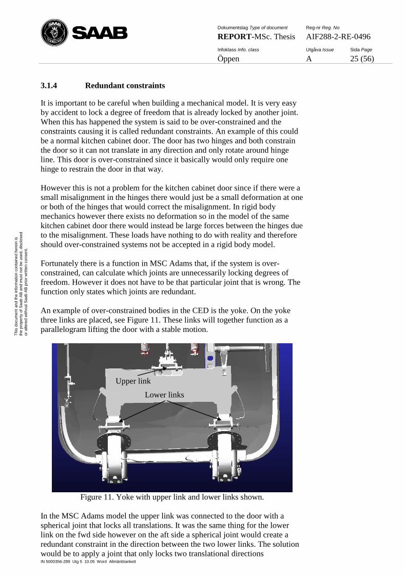
An example of over-constrained bodies in the CED is the yoke. On the yoke
three links are placed, see Figure 11. These links will together function as a
parallelogram lifting the door with a stable motion.
Figure 11. Yoke with upper link and lower links shown.
In the MSC Adams model the upper link was connected to the door with a
spherical joint that locks all translations. It was the same thing for the lower
link on the fwd side however on the aft side a spherical joint would create a
redundant constraint in the direction between the two lower links. The solution
would be to apply a joint that only locks two translational directions
Lower links
Upper link
Dokumentslag Type of document Reg-nr Reg. No
REPORT-MSc. Thesis AIF288-2-RE-0496
Infoklass Info. class Utgåva Issue Sida Page
Öppen A 26 (56)
IN 5000356-289 Utg 5 10.05 Word Allmänblankett
Th
is d
ocum
en
t an
d t
he
in
form
atio
n c
on
tain
ed
he
rein
is
the
pro
pe
rty o
f S
aa
b A
B a
nd
mu
st
no
t b
e u
sed
, d
isclo
se
d
or
alte
red
with
ou
t S
aa
b A
B p
rior
wri
tte
n c
on
sen
t.
perpendicular to a line between the lower links. Unfortunately no such joint
exist, however by combining a spherical joint with a cylindrical joint than
exactly that kind of a joint is created.
So therefore a dummy part was created and connected to the door with a
cylindrical joint at the location for the lower link on aft side. At the same
location a spherical joint connected the dummy part with the lower link.
Consequently there were no redundant constraints.
3.1.5 Modelling contact between bodies
In this subchapter it will be presented how the contacts were modelled, see
2.2.5 for more information on Contact functions.
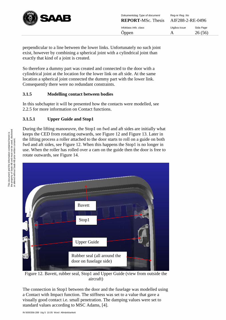
3.1.5.1 Upper Guide and Stop1
During the lifting manoeuvre, the Stop1 on fwd and aft sides are initially what
keeps the CED from rotating outwards, see Figure 12 and Figure 13. Later in
the lifting process a roller attached to the door starts to roll on a guide on both
fwd and aft sides, see Figure 12. When this happens the Stop1 is no longer in
use. When the roller has rolled over a cam on the guide then the door is free to
rotate outwards, see Figure 14.
Figure 12. Bavett, rubber seal, Stop1 and Upper Guide (view from outside the
aircraft)
The connection in Stop1 between the door and the fuselage was modelled using
a Contact with Impact function. The stiffness was set to a value that gave a
visually good contact i.e. small penetration. The damping values were set to
standard values according to MSC Adams, [4].
Upper Guide
Stop1
Bavett
Rubber seal (all around the
door on fuselage side)
Dokumentslag Type of document Reg-nr Reg. No
REPORT-MSc. Thesis AIF288-2-RE-0496
Infoklass Info. class Utgåva Issue Sida Page
Öppen A 27 (56)
IN 5000356-289 Utg 5 10.05 Word Allmänblankett
Th
is d
ocum
en
t an
d t
he
in
form
atio
n c
on
tain
ed
he
rein
is
the
pro
pe
rty o
f S
aa
b A
B a
nd
mu
st
no
t b
e u
sed
, d
isclo
se
d
or
alte
red
with
ou
t S
aa
b A
B p
rior
wri
tte
n c
on
sen
t.
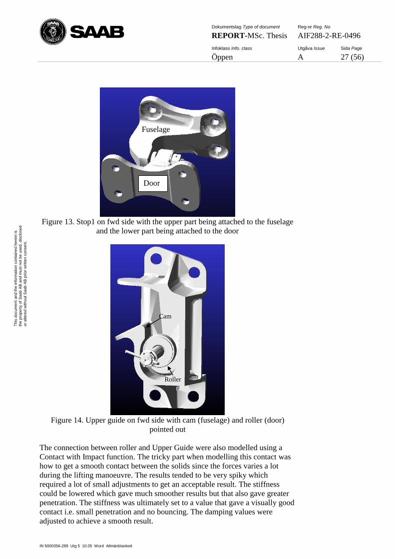
Figure 13. Stop1 on fwd side with the upper part being attached to the fuselage
and the lower part being attached to the door
Figure 14. Upper guide on fwd side with cam (fuselage) and roller (door)
pointed out
The connection between roller and Upper Guide were also modelled using a
Contact with Impact function. The tricky part when modelling this contact was
how to get a smooth contact between the solids since the forces varies a lot
during the lifting manoeuvre. The results tended to be very spiky which
required a lot of small adjustments to get an acceptable result. The stiffness
could be lowered which gave much smoother results but that also gave greater
penetration. The stiffness was ultimately set to a value that gave a visually good
contact i.e. small penetration and no bouncing. The damping values were
adjusted to achieve a smooth result.
Cam
Roller
Fuselage
Door

Dokumentslag Type of document Reg-nr Reg. No
REPORT-MSc. Thesis AIF288-2-RE-0496
Infoklass Info. class Utgåva Issue Sida Page
Öppen A 28 (56)
IN 5000356-289 Utg 5 10.05 Word Allmänblankett
Th
is d
ocum
en
t an
d t
he
in
form
atio
n c
on
tain
ed
he
rein
is
the
pro
pe
rty o
f S
aa
b A
B a
nd
mu
st
no
t b
e u
sed
, d
isclo
se
d
or
alte
red
with
ou
t S
aa
b A
B p
rior
wri
tte
n c
on
sen
t.
Another method to model the contact was also tried where a spline (tubular data
see 3.2.3) was created from the positions of a marker in centre of the roller. A
curve attached to the fuselage (ground) could then be created from that spline.
A dummy part could then be connected to the curve with a point-to-curve
constraint and finally the roller was connected to the dummy part through a
spring with variable stiffness.
Figure 15. Upper Guide on fwd side with curve (red) from spline
The complexity of this method made the modelling of the connection very time-
consuming. Before the connection was entirely finished, some simulations
could already be done. These simulations showed results that were not any
smoother than simulations with the Contact method. Risking more time-
consuming modelling, a decision was made to use the Contact method for the
Upper Guide connection.
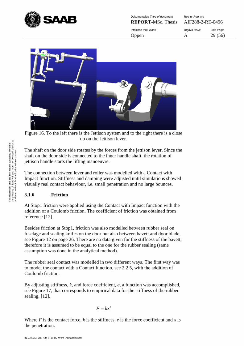
3.1.5.2 Jettison lever
When pulling at the jettison handle, a little lever on shaft attached to the
fuselage is pushing on a roller attached to a shaft on the door, see Figure 16.
Dokumentslag Type of document Reg-nr Reg. No
REPORT-MSc. Thesis AIF288-2-RE-0496
Infoklass Info. class Utgåva Issue Sida Page
Öppen A 29 (56)
IN 5000356-289 Utg 5 10.05 Word Allmänblankett
Th
is d
ocum
en
t an
d t
he
in
form
atio
n c
on
tain
ed
he
rein
is
the
pro
pe
rty o
f S
aa
b A
B a
nd
mu
st
no
t b
e u
sed
, d
isclo
se
d
or
alte
red
with
ou
t S
aa
b A
B p
rior
wri
tte
n c
on
sen
t.
Figure 16. To the left there is the Jettison system and to the right there is a close
up on the Jettison lever.
The shaft on the door side rotates by the forces from the jettison lever. Since the
shaft on the door side is connected to the inner handle shaft, the rotation of
jettison handle starts the lifting manoeuvre.
The connection between lever and roller was modelled with a Contact with
Impact function. Stiffness and damping were adjusted until simulations showed
visually real contact behaviour, i.e. small penetration and no large bounces.
3.1.6 Friction
At Stop1 friction were applied using the Contact with Impact function with the
addition of a Coulomb friction. The coefficient of friction was obtained from
reference [12].
Besides friction at Stop1, friction was also modelled between rubber seal on
fuselage and sealing knifes on the door but also between bavett and door blade,
see Figure 12 on page 26. There are no data given for the stiffness of the bavett,
therefore it is assumed to be equal to the one for the rubber sealing (same
assumption was done in the analytical method).
The rubber seal contact was modelled in two different ways. The first way was
to model the contact with a Contact function, see 2.2.5, with the addition of
Coulomb friction.
By adjusting stiffness, k, and force coefficient, e, a function was accomplished,
see Figure 17, that corresponds to empirical data for the stiffness of the rubber
sealing, [12].
ekxF
Where F is the contact force, k is the stiffness, e is the force coefficient and x is
the penetration.
Dokumentslag Type of document Reg-nr Reg. No
REPORT-MSc. Thesis AIF288-2-RE-0496
Infoklass Info. class Utgåva Issue Sida Page
Öppen A 30 (56)
IN 5000356-289 Utg 5 10.05 Word Allmänblankett
Th
is d
ocum
en
t an
d t
he
in
form
atio
n c
on
tain
ed
he
rein
is
the
pro
pe
rty o
f S
aa
b A
B a
nd
mu
st
no
t b
e u
sed
, d
isclo
se
d
or
alte
red
with
ou
t S
aa
b A
B p
rior
wri
tte
n c
on
sen
t.
Load vs. Penetration
0
50
100
150
200
250
0 2 4 6 8 10 12 14
Penetration [mm]
Lin
ea
r lo
ad
[N
/m]
Adams approximation
Measured stiffness
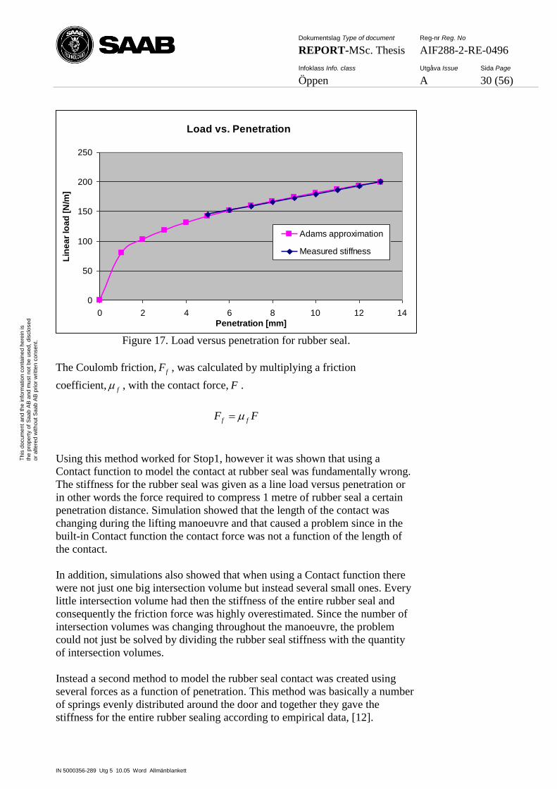
Figure 17. Load versus penetration for rubber seal.
The Coulomb friction, fF , was calculated by multiplying a friction
coefficient, f , with the contact force, F .
FF ff
Using this method worked for Stop1, however it was shown that using a
Contact function to model the contact at rubber seal was fundamentally wrong.
The stiffness for the rubber seal was given as a line load versus penetration or
in other words the force required to compress 1 metre of rubber seal a certain
penetration distance. Simulation showed that the length of the contact was
changing during the lifting manoeuvre and that caused a problem since in the
built-in Contact function the contact force was not a function of the length of
the contact.
In addition, simulations also showed that when using a Contact function there
were not just one big intersection volume but instead several small ones. Every
little intersection volume had then the stiffness of the entire rubber seal and
consequently the friction force was highly overestimated. Since the number of
intersection volumes was changing throughout the manoeuvre, the problem
could not just be solved by dividing the rubber seal stiffness with the quantity
of intersection volumes.
Instead a second method to model the rubber seal contact was created using
several forces as a function of penetration. This method was basically a number
of springs evenly distributed around the door and together they gave the
stiffness for the entire rubber sealing according to empirical data, [12].
Dokumentslag Type of document Reg-nr Reg. No
REPORT-MSc. Thesis AIF288-2-RE-0496
Infoklass Info. class Utgåva Issue Sida Page
Öppen A 31 (56)
IN 5000356-289 Utg 5 10.05 Word Allmänblankett
Th
is d
ocum
en
t an
d t
he
in
form
atio
n c
on
tain
ed
he
rein
is
the
pro
pe
rty o
f S
aa
b A
B a
nd
mu
st
no
t b
e u
sed
, d
isclo
se
d
or
alte
red
with
ou
t S
aa
b A
B p
rior
wri
tte
n c
on
sen
t.
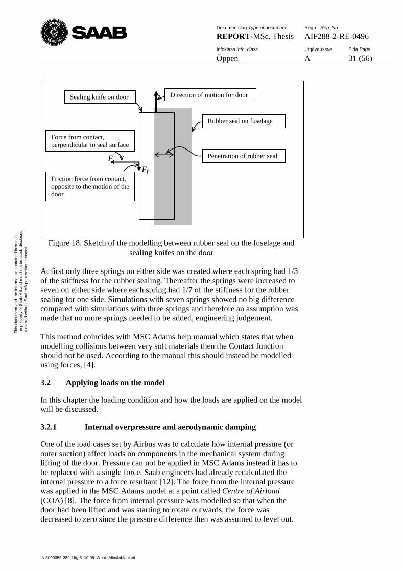
Figure 18. Sketch of the modelling between rubber seal on the fuselage and
sealing knifes on the door
At first only three springs on either side was created where each spring had 1/3
of the stiffness for the rubber sealing. Thereafter the springs were increased to
seven on either side where each spring had 1/7 of the stiffness for the rubber
sealing for one side. Simulations with seven springs showed no big difference
compared with simulations with three springs and therefore an assumption was
made that no more springs needed to be added, engineering judgement.
This method coincides with MSC Adams help manual which states that when
modelling collisions between very soft materials then the Contact function
should not be used. According to the manual this should instead be modelled
using forces, [4].
3.2 Applying loads on the model
In this chapter the loading condition and how the loads are applied on the model
will be discussed.
3.2.1 Internal overpressure and aerodynamic damping
One of the load cases set by Airbus was to calculate how internal pressure (or
outer suction) affect loads on components in the mechanical system during
lifting of the door. Pressure can not be applied in MSC Adams instead it has to
be replaced with a single force. Saab engineers had already recalculated the
internal pressure to a force resultant [12]. The force from the internal pressure
was applied in the MSC Adams model at a point called Centre of Airload
(COA) [8]. The force from internal pressure was modelled so that when the
door had been lifted and was starting to rotate outwards, the force was
decreased to zero since the pressure difference then was assumed to level out.
Rubber seal on fuselage
Sealing knife on door Direction of motion for door
Penetration of rubber seal F
Ff
Force from contact,
perpendicular to seal surface
Friction force from contact,
opposite to the motion of the
door
Dokumentslag Type of document Reg-nr Reg. No
REPORT-MSc. Thesis AIF288-2-RE-0496
Infoklass Info. class Utgåva Issue Sida Page
Öppen A 32 (56)
IN 5000356-289 Utg 5 10.05 Word Allmänblankett
Th
is d
ocum
en
t an
d t
he
in
form
atio
n c
on
tain
ed
he
rein
is
the
pro
pe
rty o
f S
aa
b A
B a
nd
mu
st
no
t b
e u
sed
, d
isclo
se
d
or
alte
red
with
ou
t S
aa
b A
B p
rior
wri
tte
n c
on
sen
t.
An aerodynamic damping force was applied to simulate the air drag during
opening of the door. The damping was assumed to be a function of the angular
velocity of the hinges, see Figure 2, [9].
coacoa
damping
dampingl
c
l
MF
Where M is the moment around the hinges, dampingF is the load with the lever
coal that creates the moment M, c is the damping coefficient and is the
angular velocity.
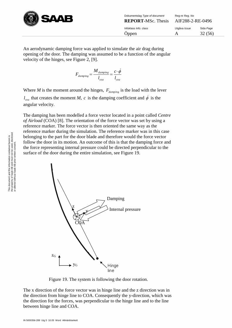
The damping has been modelled a force vector located in a point called Centre
of Airload (COA) [8]. The orientation of the force vector was set by using a
reference marker. The force vector is then oriented the same way as the
reference marker during the simulation. The reference marker was in this case
belonging to the part for the door blade and therefore would the force vector
follow the door in its motion. An outcome of this is that the damping force and
the force representing internal pressure could be directed perpendicular to the
surface of the door during the entire simulation, see Figure 19.
Figure 19. The system is following the door rotation.
The x direction of the force vector was in hinge line and the z direction was in
the direction from hinge line to COA. Consequently the y-direction, which was
the direction for the forces, was perpendicular to the hinge line and to the line
between hinge line and COA.
z
COA
Internal pressure
Damping
zG
yG
y
Dokumentslag Type of document Reg-nr Reg. No
REPORT-MSc. Thesis AIF288-2-RE-0496
Infoklass Info. class Utgåva Issue Sida Page
Öppen A 33 (56)
IN 5000356-289 Utg 5 10.05 Word Allmänblankett
Th
is d
ocum
en
t an
d t
he
in
form
atio
n c
on
tain
ed
he
rein
is
the
pro
pe
rty o
f S
aa
b A
B a
nd
mu
st
no
t b
e u
sed
, d
isclo
se
d
or
alte
red
with
ou
t S
aa
b A
B p
rior
wri
tte
n c
on
sen
t.
3.2.2 Aerodynamic forces during Jettison
Airbus has decided that the CED should be able to jettison during high velocity
flight with low altitude and with a high angle of attack. Saab has, with CFD
software, calculated aerodynamic forces on the CED during these conditions for
different opening angles. The aerodynamic forces were presented in a fix hinge
line system, [9], see Figure 20.
Figure 20. The fixed hinge line system was not following the door in its rotation
To apply the force vector for aerodynamic loads in the correct orientation, a
reference marker added to ground was used. The reference marker was oriented
such as the x-direction was in hinge line, z-direction was in global z-direction
and y-direction was then perpendicular to both x- and z-direction.
In the result from the CFD analysis, the loads had been recalculated to be
applied at hinge line instead of at COA with an effect of correcting moments. In
the model the loads were placed in the COA resulting with that the correcting
moments could be discarded.
3.2.3 Wind loads
Airbus has decided that the Crew Entrance Door for A400M should be able to
be opened when subjected to wind loads in both opening and closing wind
directions. Wind loads on the CED during opening have been calculated by
Saab using FORTRAN software, [11]. The wind loads consist of forces in three
directions and moments around those three axes for different opening angles of
the CED. To simplify the managing of large amount of input data, the data was
imported as splines.
COA
z
y
zG
yG
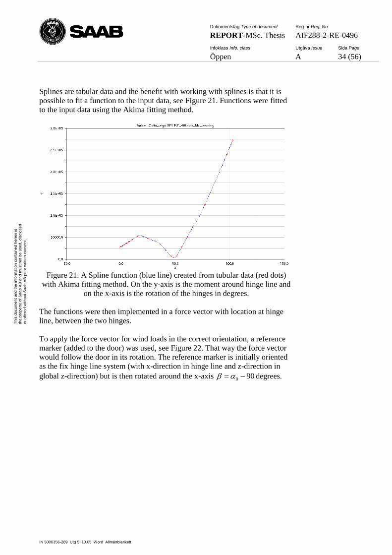
Dokumentslag Type of document Reg-nr Reg. No
REPORT-MSc. Thesis AIF288-2-RE-0496
Infoklass Info. class Utgåva Issue Sida Page
Öppen A 34 (56)
IN 5000356-289 Utg 5 10.05 Word Allmänblankett
Th
is d
ocum
en
t an
d t
he
in
form
atio
n c
on
tain
ed
he
rein
is
the
pro
pe
rty o
f S
aa
b A
B a
nd
mu
st
no
t b
e u
sed
, d
isclo
se
d
or
alte
red
with
ou
t S
aa
b A
B p
rior
wri
tte
n c
on
sen
t.
Splines are tabular data and the benefit with working with splines is that it is
possible to fit a function to the input data, see Figure 21. Functions were fitted
to the input data using the Akima fitting method.
Figure 21. A Spline function (blue line) created from tubular data (red dots)
with Akima fitting method. On the y-axis is the moment around hinge line and
on the x-axis is the rotation of the hinges in degrees.
The functions were then implemented in a force vector with location at hinge
line, between the two hinges.
To apply the force vector for wind loads in the correct orientation, a reference
marker (added to the door) was used, see Figure 22. That way the force vector
would follow the door in its rotation. The reference marker is initially oriented
as the fix hinge line system (with x-direction in hinge line and z-direction in
global z-direction) but is then rotated around the x-axis 900 degrees.
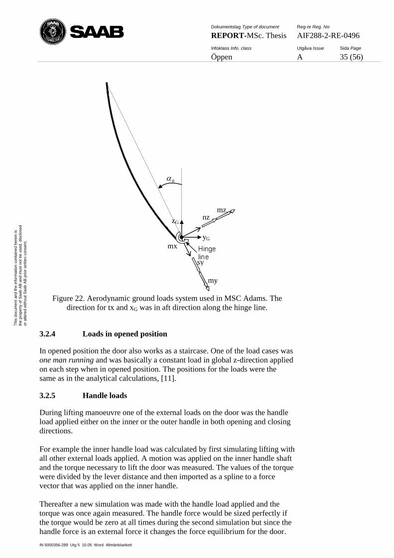
Dokumentslag Type of document Reg-nr Reg. No
REPORT-MSc. Thesis AIF288-2-RE-0496
Infoklass Info. class Utgåva Issue Sida Page
Öppen A 35 (56)
IN 5000356-289 Utg 5 10.05 Word Allmänblankett
Th
is d
ocum
en
t an
d t
he
in
form
atio
n c
on
tain
ed
he
rein
is
the
pro
pe
rty o
f S
aa
b A
B a
nd
mu
st
no
t b
e u
sed
, d
isclo
se
d
or
alte
red
with
ou
t S
aa
b A
B p
rior
wri
tte
n c
on
sen
t.
Figure 22. Aerodynamic ground loads system used in MSC Adams. The
direction for tx and xG was in aft direction along the hinge line.
3.2.4 Loads in opened position
In opened position the door also works as a staircase. One of the load cases was
one man running and was basically a constant load in global z-direction applied
on each step when in opened position. The positions for the loads were the
same as in the analytical calculations, [11].
3.2.5 Handle loads
During lifting manoeuvre one of the external loads on the door was the handle
load applied either on the inner or the outer handle in both opening and closing
directions.
For example the inner handle load was calculated by first simulating lifting with
all other external loads applied. A motion was applied on the inner handle shaft
and the torque necessary to lift the door was measured. The values of the torque
were divided by the lever distance and then imported as a spline to a force
vector that was applied on the inner handle.
Thereafter a new simulation was made with the handle load applied and the
torque was once again measured. The handle force would be sized perfectly if
the torque would be zero at all times during the second simulation but since the
handle force is an external force it changes the force equilibrium for the door.
zG
yG
sy
my
nz mz
0
mx

Dokumentslag Type of document Reg-nr Reg. No
REPORT-MSc. Thesis AIF288-2-RE-0496
Infoklass Info. class Utgåva Issue Sida Page
Öppen A 36 (56)
IN 5000356-289 Utg 5 10.05 Word Allmänblankett
Th
is d
ocum
en
t an
d t
he
in
form
atio
n c
on
tain
ed
he
rein
is
the
pro
pe
rty o
f S
aa
b A
B a
nd
mu
st
no
t b
e u
sed
, d
isclo
se
d
or
alte
red
with
ou
t S
aa
b A
B p
rior
wri
tte
n c
on
sen
t.
To minimize the torque values, the handle force were adjusted a few percent up
or down.
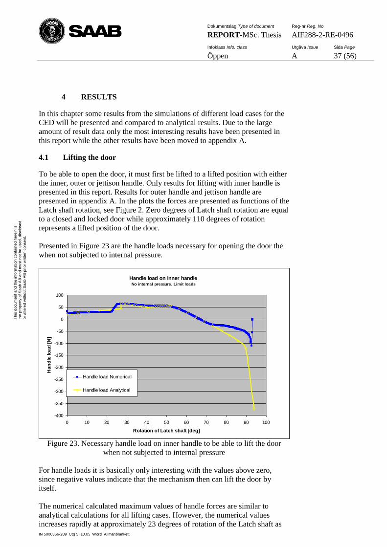
Dokumentslag Type of document Reg-nr Reg. No
REPORT-MSc. Thesis AIF288-2-RE-0496
Infoklass Info. class Utgåva Issue Sida Page
Öppen A 37 (56)
IN 5000356-289 Utg 5 10.05 Word Allmänblankett
Th
is d
ocum
en
t an
d t
he
in
form
atio
n c
on
tain
ed
he
rein
is
the
pro
pe
rty o
f S
aa
b A
B a
nd
mu
st
no
t b
e u
sed
, d
isclo
se
d
or
alte
red
with
ou
t S
aa
b A
B p
rior
wri
tte
n c
on
sen
t.
4 RESULTS
In this chapter some results from the simulations of different load cases for the
CED will be presented and compared to analytical results. Due to the large
amount of result data only the most interesting results have been presented in
this report while the other results have been moved to appendix A.
4.1 Lifting the door
To be able to open the door, it must first be lifted to a lifted position with either
the inner, outer or jettison handle. Only results for lifting with inner handle is
presented in this report. Results for outer handle and jettison handle are
presented in appendix A. In the plots the forces are presented as functions of the
Latch shaft rotation, see Figure 2. Zero degrees of Latch shaft rotation are equal
to a closed and locked door while approximately 110 degrees of rotation
represents a lifted position of the door.
Presented in Figure 23 are the handle loads necessary for opening the door the
when not subjected to internal pressure.
Handle load on inner handleNo internal pressure. Limit loads
-400
-350
-300
-250
-200
-150
-100
-50
0
50
100
0 10 20 30 40 50 60 70 80 90 100
Rotation of Latch shaft [deg]
Ha
nd
le lo
ad
[N
]
Handle load Numerical
Handle load Analytical
Figure 23. Necessary handle load on inner handle to be able to lift the door
when not subjected to internal pressure
For handle loads it is basically only interesting with the values above zero,
since negative values indicate that the mechanism then can lift the door by
itself.
The numerical calculated maximum values of handle forces are similar to
analytical calculations for all lifting cases. However, the numerical values
increases rapidly at approximately 23 degrees of rotation of the Latch shaft as
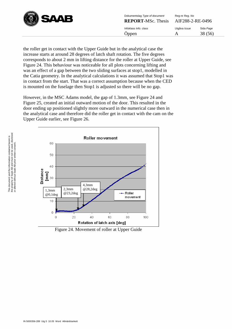
Dokumentslag Type of document Reg-nr Reg. No
REPORT-MSc. Thesis AIF288-2-RE-0496
Infoklass Info. class Utgåva Issue Sida Page
Öppen A 38 (56)
IN 5000356-289 Utg 5 10.05 Word Allmänblankett
Th
is d
ocum
en
t an
d t
he
in
form
atio
n c
on
tain
ed
he
rein
is
the
pro
pe
rty o
f S
aa
b A
B a
nd
mu
st
no
t b
e u
sed
, d
isclo
se
d
or
alte
red
with
ou
t S
aa
b A
B p
rior
wri
tte
n c
on
sen
t.
the roller get in contact with the Upper Guide but in the analytical case the
increase starts at around 28 degrees of latch shaft rotation. The five degrees
corresponds to about 2 mm in lifting distance for the roller at Upper Guide, see
Figure 24. This behaviour was noticeable for all plots concerning lifting and
was an effect of a gap between the two sliding surfaces at stop1, modelled in
the Catia geometry. In the analytical calculations it was assumed that Stop1 was
in contact from the start. That was a correct assumption because when the CED
is mounted on the fuselage then Stop1 is adjusted so there will be no gap.
However, in the MSC Adams model, the gap of 1.3mm, see Figure 24 and
Figure 25, created an initial outward motion of the door. This resulted in the
door ending up positioned slightly more outward in the numerical case then in
the analytical case and therefore did the roller get in contact with the cam on the
Upper Guide earlier, see Figure 26.
Figure 24. Movement of roller at Upper Guide
2,3mm
@23,2deg
4,3mm
@28,2deg 1,3mm
@0,1deg
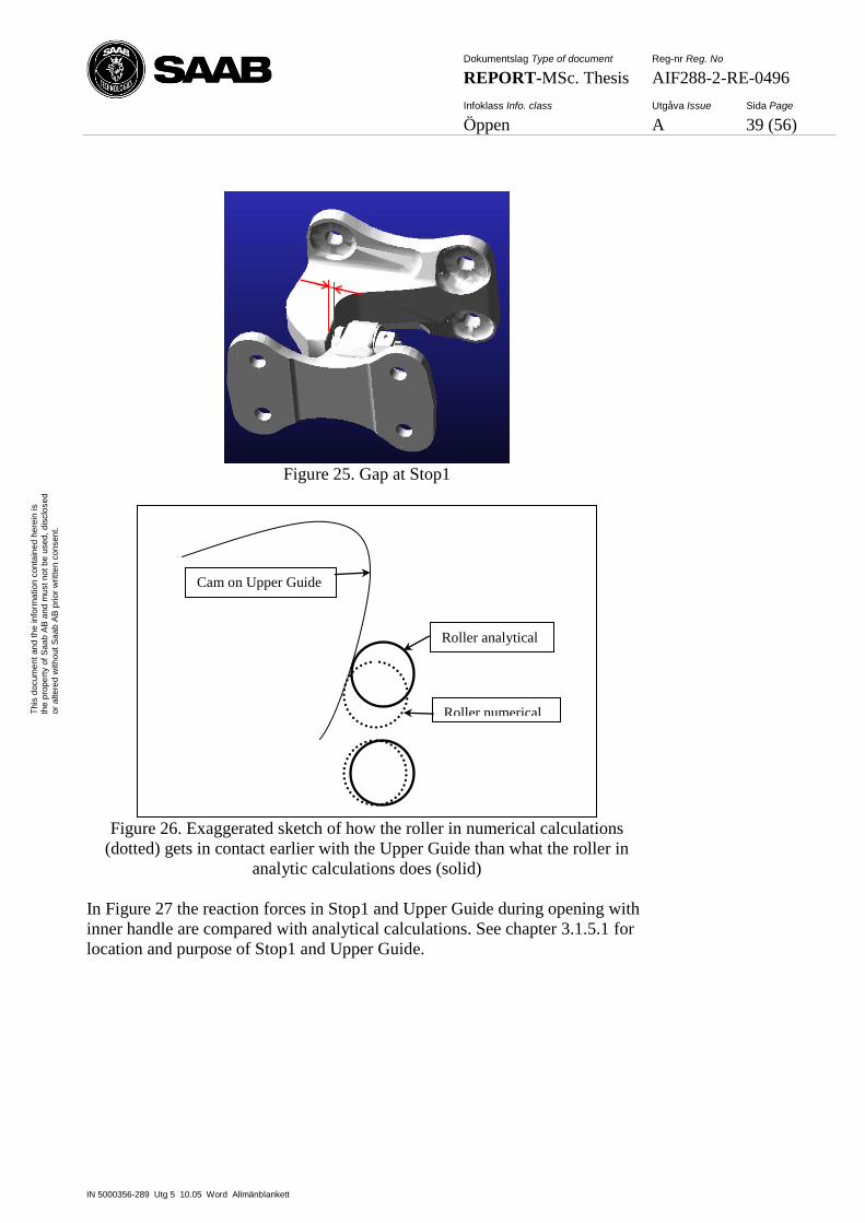
Dokumentslag Type of document Reg-nr Reg. No
REPORT-MSc. Thesis AIF288-2-RE-0496
Infoklass Info. class Utgåva Issue Sida Page
Öppen A 39 (56)
IN 5000356-289 Utg 5 10.05 Word Allmänblankett
Th
is d
ocum
en
t an
d t
he
in
form
atio
n c
on
tain
ed
he
rein
is
the
pro
pe
rty o
f S
aa
b A
B a
nd
mu
st
no
t b
e u
sed
, d
isclo
se
d
or
alte
red
with
ou
t S
aa
b A
B p
rior
wri
tte
n c
on
sen
t.
Figure 25. Gap at Stop1
Figure 26. Exaggerated sketch of how the roller in numerical calculations
(dotted) gets in contact earlier with the Upper Guide than what the roller in
analytic calculations does (solid)
In Figure 27 the reaction forces in Stop1 and Upper Guide during opening with
inner handle are compared with analytical calculations. See chapter 3.1.5.1 for
location and purpose of Stop1 and Upper Guide.
Roller analytical
Roller numerical
Cam on Upper Guide
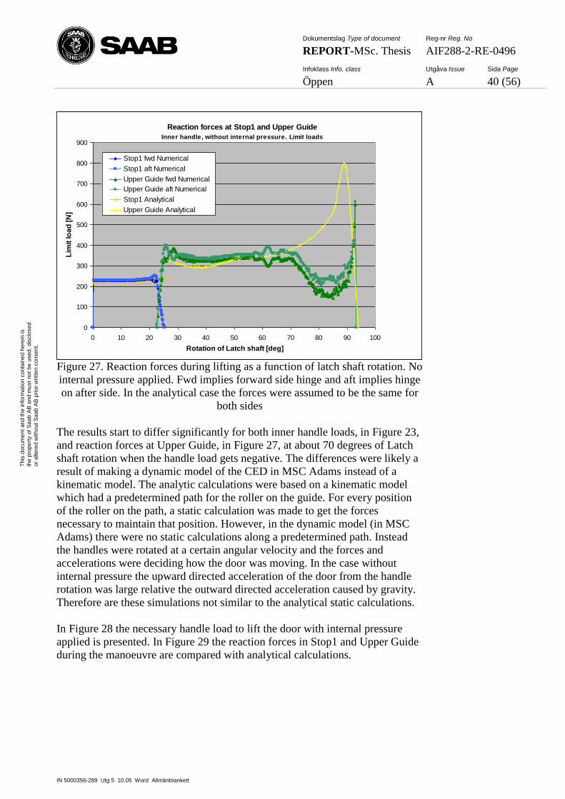
Dokumentslag Type of document Reg-nr Reg. No
REPORT-MSc. Thesis AIF288-2-RE-0496
Infoklass Info. class Utgåva Issue Sida Page
Öppen A 40 (56)
IN 5000356-289 Utg 5 10.05 Word Allmänblankett
Th
is d
ocum
en
t an
d t
he
in
form
atio
n c
on
tain
ed
he
rein
is
the
pro
pe
rty o
f S
aa
b A
B a
nd
mu
st
no
t b
e u
sed
, d
isclo
se
d
or
alte
red
with
ou
t S
aa
b A
B p
rior
wri
tte
n c
on
sen
t.
Reaction forces at Stop1 and Upper Guide
Inner handle, without internal pressure. Limit loads
0
100
200
300
400
500
600
700
800
900
0 10 20 30 40 50 60 70 80 90 100
Rotation of Latch shaft [deg]
Lim
it lo
ad
[N
]
Stop1 fwd Numerical
Stop1 aft Numerical
Upper Guide fwd Numerical
Upper Guide aft Numerical
Stop1 Analytical
Upper Guide Analytical
Figure 27. Reaction forces during lifting as a function of latch shaft rotation. No
internal pressure applied. Fwd implies forward side hinge and aft implies hinge
on after side. In the analytical case the forces were assumed to be the same for
both sides
The results start to differ significantly for both inner handle loads, in Figure 23,
and reaction forces at Upper Guide, in Figure 27, at about 70 degrees of Latch
shaft rotation when the handle load gets negative. The differences were likely a
result of making a dynamic model of the CED in MSC Adams instead of a
kinematic model. The analytic calculations were based on a kinematic model
which had a predetermined path for the roller on the guide. For every position
of the roller on the path, a static calculation was made to get the forces
necessary to maintain that position. However, in the dynamic model (in MSC
Adams) there were no static calculations along a predetermined path. Instead
the handles were rotated at a certain angular velocity and the forces and
accelerations were deciding how the door was moving. In the case without
internal pressure the upward directed acceleration of the door from the handle
rotation was large relative the outward directed acceleration caused by gravity.
Therefore are these simulations not similar to the analytical static calculations.
In Figure 28 the necessary handle load to lift the door with internal pressure
applied is presented. In Figure 29 the reaction forces in Stop1 and Upper Guide
during the manoeuvre are compared with analytical calculations.
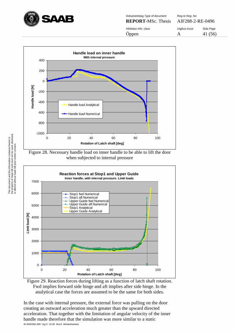
Dokumentslag Type of document Reg-nr Reg. No
REPORT-MSc. Thesis AIF288-2-RE-0496
Infoklass Info. class Utgåva Issue Sida Page
Öppen A 41 (56)
IN 5000356-289 Utg 5 10.05 Word Allmänblankett
Th
is d
ocum
en
t an
d t
he
in
form
atio
n c
on
tain
ed
he
rein
is
the
pro
pe
rty o
f S
aa
b A
B a
nd
mu
st
no
t b
e u
sed
, d
isclo
se
d
or
alte
red
with
ou
t S
aa
b A
B p
rior
wri
tte
n c
on
sen
t.
Handle load on inner handleWith internal pressure
-1000
-800
-600
-400
-200
0
200
400
0 20 40 60 80 100
Rotation of Latch shaft [deg]
Ha
nd
le lo
ad
[N
]
Handle load Analytical
Handle load Numerical
Figure 28. Necessary handle load on inner handle to be able to lift the door
when subjected to internal pressure
Reaction forces at Stop1 and Upper GuideInner handle, with internal pressure. Limit loads
0
1000
2000
3000
4000
5000
6000
7000
0 20 40 60 80 100
Rotation of Latch shaft [deg]
Lim
it lo
ad
[N
]
Stop1 fwd NumericalStop1 aft NumericalUpper Guide fwd NumericalUpper Guide aft NumericalStop1 AnalyticalUpper Guide Analytical
Figure 29. Reaction forces during lifting as a function of latch shaft rotation.
Fwd implies forward side hinge and aft implies after side hinge. In the
analytical case the forces are assumed to be the same for both sides.
In the case with internal pressure, the external force was pulling on the door
creating an outward acceleration much greater than the upward directed
acceleration. That together with the limitation of angular velocity of the inner
handle made therefore that the simulation was more similar to a static
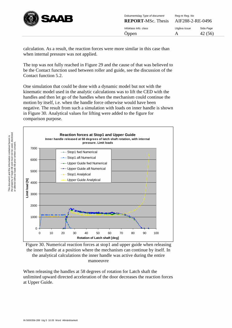
Dokumentslag Type of document Reg-nr Reg. No
REPORT-MSc. Thesis AIF288-2-RE-0496
Infoklass Info. class Utgåva Issue Sida Page
Öppen A 42 (56)
IN 5000356-289 Utg 5 10.05 Word Allmänblankett
Th
is d
ocum
en
t an
d t
he
in
form
atio
n c
on
tain
ed
he
rein
is
the
pro
pe
rty o
f S
aa
b A
B a
nd
mu
st
no
t b
e u
sed
, d
isclo
se
d
or
alte
red
with
ou
t S
aa
b A
B p
rior
wri
tte
n c
on
sen
t.
calculation. As a result, the reaction forces were more similar in this case than
when internal pressure was not applied.
The top was not fully reached in Figure 29 and the cause of that was believed to
be the Contact function used between roller and guide, see the discussion of the
Contact function 5.2.
One simulation that could be done with a dynamic model but not with the
kinematic model used in the analytic calculations was to lift the CED with the
handles and then let go of the handles when the mechanism could continue the
motion by itself, i.e. when the handle force otherwise would have been
negative. The result from such a simulation with loads on inner handle is shown
in Figure 30. Analytical values for lifting were added to the figure for
comparison purpose.
Reaction forces at Stop1 and Upper GuideInner handle released at 58 degrees of latch shaft rotation, with internal
pressure. Limit loads
0
1000
2000
3000
4000
5000
6000
7000
0 10 20 30 40 50 60 70 80 90 100
Rotation of Latch shaft [deg]
Lim
it lo
ad
[N
]
Stop1 fwd Numerical
Stop1 aft Numerical
Upper Guide fwd Numerical
Upper Guide aft Numerical
Stop1 Analytical
Upper Guide Analytical
Figure 30. Numerical reaction forces at stop1 and upper guide when releasing
the inner handle at a position where the mechanism can continue by itself. In
the analytical calculations the inner handle was active during the entire
manoeuvre
When releasing the handles at 58 degrees of rotation for Latch shaft the
unlimited upward directed acceleration of the door decreases the reaction forces
at Upper Guide.
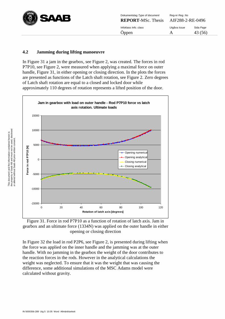
Dokumentslag Type of document Reg-nr Reg. No
REPORT-MSc. Thesis AIF288-2-RE-0496
Infoklass Info. class Utgåva Issue Sida Page
Öppen A 43 (56)
IN 5000356-289 Utg 5 10.05 Word Allmänblankett
Th
is d
ocum
en
t an
d t
he
in
form
atio
n c
on
tain
ed
he
rein
is
the
pro
pe
rty o
f S
aa
b A
B a
nd
mu
st
no
t b
e u
sed
, d
isclo
se
d
or
alte
red
with
ou
t S
aa
b A
B p
rior
wri
tte
n c
on
sen
t.
4.2 Jamming during lifting manoeuvre
In Figure 31 a jam in the gearbox, see Figure 2, was created. The forces in rod
P7P10, see Figure 2, were measured when applying a maximal force on outer
handle, Figure 31, in either opening or closing direction. In the plots the forces
are presented as functions of the Latch shaft rotation, see Figure 2. Zero degrees
of Latch shaft rotation are equal to a closed and locked door while
approximately 110 degrees of rotation represents a lifted position of the door.
Jam in gearbox with load on outer handle - Rod P7P10 force vs latch
axis rotation. Ultimate loads
-15000
-10000
-5000
0
5000
10000
15000
0 20 40 60 80 100 120
Rotation of latch axis [degrees]
Fo
rce i
n r
od
P7P
10 [
N]
Opening numerical
Opening analytical
Closing numerical
Closing analytical
Figure 31. Force in rod P7P10 as a function of rotation of latch axis. Jam in
gearbox and an ultimate force (1334N) was applied on the outer handle in either
opening or closing direction
In Figure 32 the load in rod P2P6, see Figure 2, is presented during lifting when
the force was applied on the inner handle and the jamming was at the outer
handle. With no jamming in the gearbox the weight of the door contributes to
the reaction forces in the rods. However in the analytical calculations the
weight was neglected. To ensure that it was the weight that was causing the
difference, some additional simulations of the MSC Adams model were
calculated without gravity.
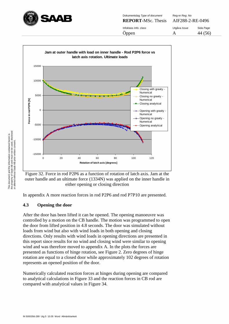
Dokumentslag Type of document Reg-nr Reg. No
REPORT-MSc. Thesis AIF288-2-RE-0496
Infoklass Info. class Utgåva Issue Sida Page
Öppen A 44 (56)
IN 5000356-289 Utg 5 10.05 Word Allmänblankett
Th
is d
ocum
en
t an
d t
he
in
form
atio
n c
on
tain
ed
he
rein
is
the
pro
pe
rty o
f S
aa
b A
B a
nd
mu
st
no
t b
e u
sed
, d
isclo
se
d
or
alte
red
with
ou
t S
aa
b A
B p
rior
wri
tte
n c
on
sen
t.
Jam at outer handle with load on inner handle - Rod P2P6 force vs
latch axis rotation. Ultimate loads
-15000
-10000
-5000
0
5000
10000
15000
0 20 40 60 80 100 120
Rotation of latch axis [degrees]
Fo
rce
in
ro
d P
2P
6 [
N]
Closing with gravity -
Numerical
Closing no gravity -
Numerical
Closing analytical
Opening with gravity -
Numerical
Opening no gravity -
Numerical
Opening analytical
Figure 32. Force in rod P2P6 as a function of rotation of latch axis. Jam at the
outer handle and an ultimate force (1334N) was applied on the inner handle in
either opening or closing direction
In appendix A more reaction forces in rod P2P6 and rod P7P10 are presented.
4.3 Opening the door
After the door has been lifted it can be opened. The opening manoeuvre was
controlled by a motion on the CB handle. The motion was programmed to open
the door from lifted position in 4.8 seconds. The door was simulated without
loads from wind but also with wind loads in both opening and closing
directions. Only results with wind loads in opening directions are presented in
this report since results for no wind and closing wind were similar to opening
wind and was therefore moved to appendix A. In the plots the forces are
presented as functions of hinge rotation, see Figure 2. Zero degrees of hinge
rotation are equal to a closed door while approximately 102 degrees of rotation
represents an opened position of the door.
Numerically calculated reaction forces at hinges during opening are compared
to analytical calculations in Figure 33 and the reaction forces in CB rod are
compared with analytical values in Figure 34.
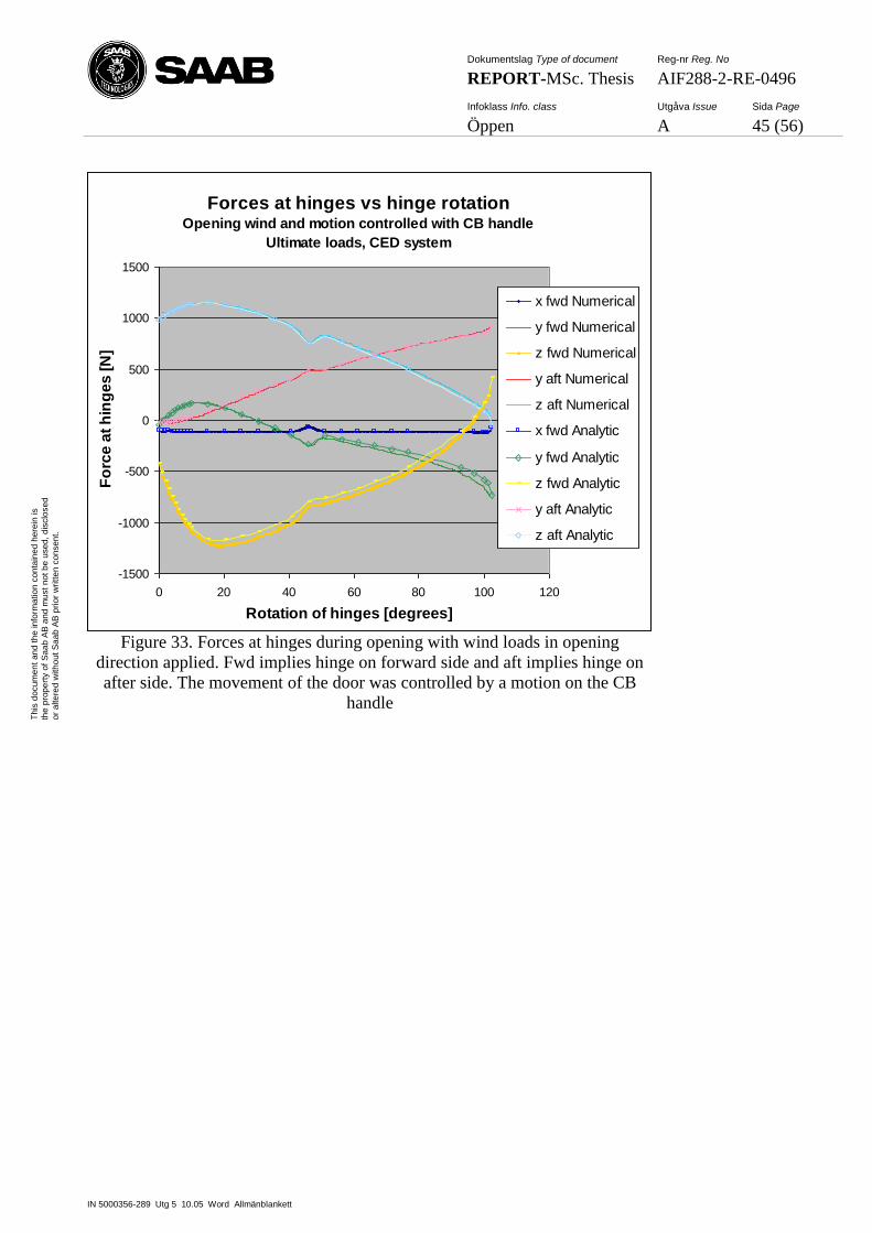
Dokumentslag Type of document Reg-nr Reg. No
REPORT-MSc. Thesis AIF288-2-RE-0496
Infoklass Info. class Utgåva Issue Sida Page
Öppen A 45 (56)
IN 5000356-289 Utg 5 10.05 Word Allmänblankett
Th
is d
ocum
en
t an
d t
he
in
form
atio
n c
on
tain
ed
he
rein
is
the
pro
pe
rty o
f S
aa
b A
B a
nd
mu
st
no
t b
e u
sed
, d
isclo
se
d
or
alte
red
with
ou
t S
aa
b A
B p
rior
wri
tte
n c
on
sen
t.
Forces at hinges vs hinge rotationOpening wind and motion controlled with CB handle
Ultimate loads, CED system
-1500
-1000
-500
0
500
1000
1500
0 20 40 60 80 100 120
Rotation of hinges [degrees]
Fo
rce
at
hin
ge
s [
N]
x fwd Numerical
y fwd Numerical
z fwd Numerical
y aft Numerical
z aft Numerical
x fwd Analytic
y fwd Analytic
z fwd Analytic
y aft Analytic
z aft Analytic
Figure 33. Forces at hinges during opening with wind loads in opening
direction applied. Fwd implies hinge on forward side and aft implies hinge on
after side. The movement of the door was controlled by a motion on the CB
handle
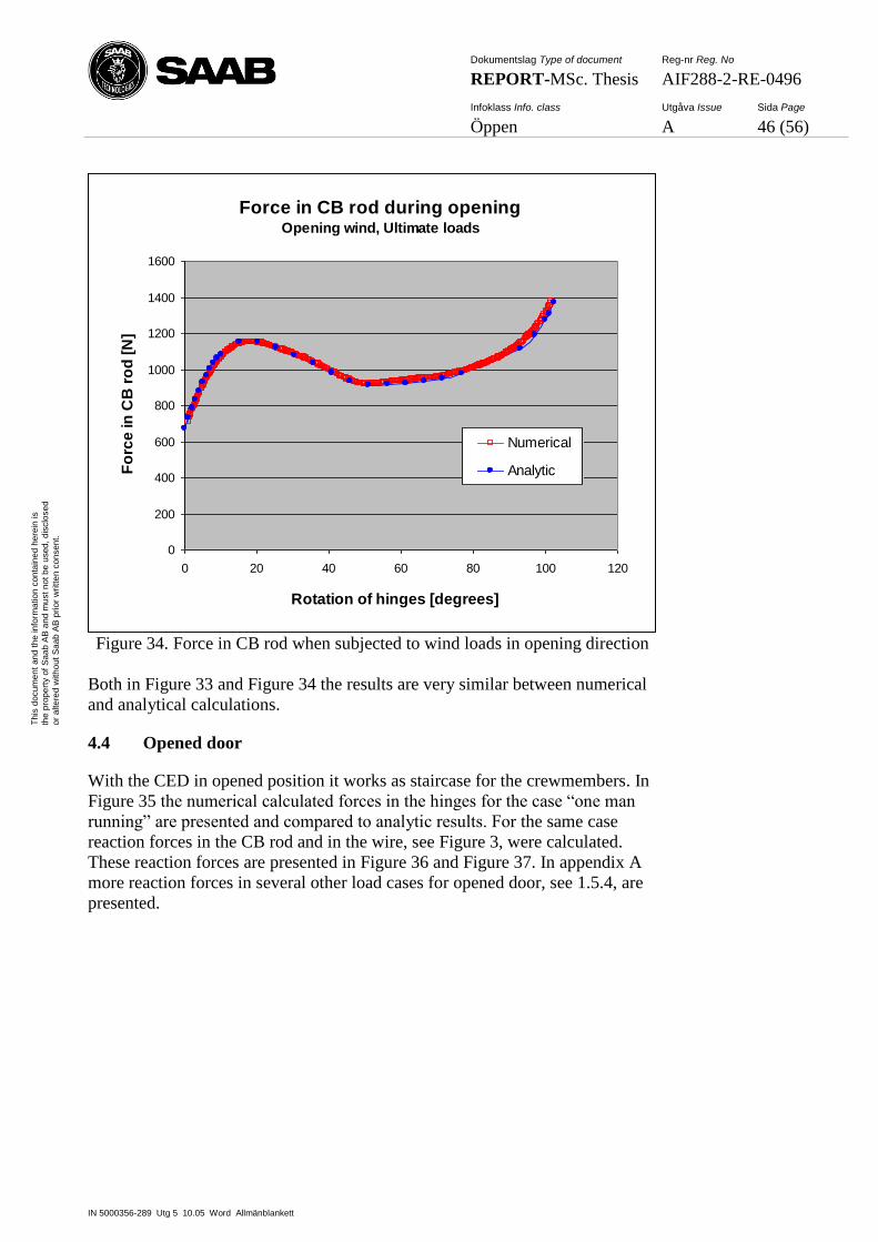
Dokumentslag Type of document Reg-nr Reg. No
REPORT-MSc. Thesis AIF288-2-RE-0496
Infoklass Info. class Utgåva Issue Sida Page
Öppen A 46 (56)
IN 5000356-289 Utg 5 10.05 Word Allmänblankett
Th
is d
ocum
en
t an
d t
he
in
form
atio
n c
on
tain
ed
he
rein
is
the
pro
pe
rty o
f S
aa
b A
B a
nd
mu
st
no
t b
e u
sed
, d
isclo
se
d
or
alte
red
with
ou
t S
aa
b A
B p
rior
wri
tte
n c
on
sen
t.
Force in CB rod during openingOpening wind, Ultimate loads
0
200
400
600
800
1000
1200
1400
1600
0 20 40 60 80 100 120
Rotation of hinges [degrees]
Fo
rce
in
CB
ro
d [
N]
Numerical
Analytic
Figure 34. Force in CB rod when subjected to wind loads in opening direction
Both in Figure 33 and Figure 34 the results are very similar between numerical
and analytical calculations.
4.4 Opened door
With the CED in opened position it works as staircase for the crewmembers. In
Figure 35 the numerical calculated forces in the hinges for the case “one man
running” are presented and compared to analytic results. For the same case
reaction forces in the CB rod and in the wire, see Figure 3, were calculated.
These reaction forces are presented in Figure 36 and Figure 37. In appendix A
more reaction forces in several other load cases for opened door, see 1.5.4, are
presented.
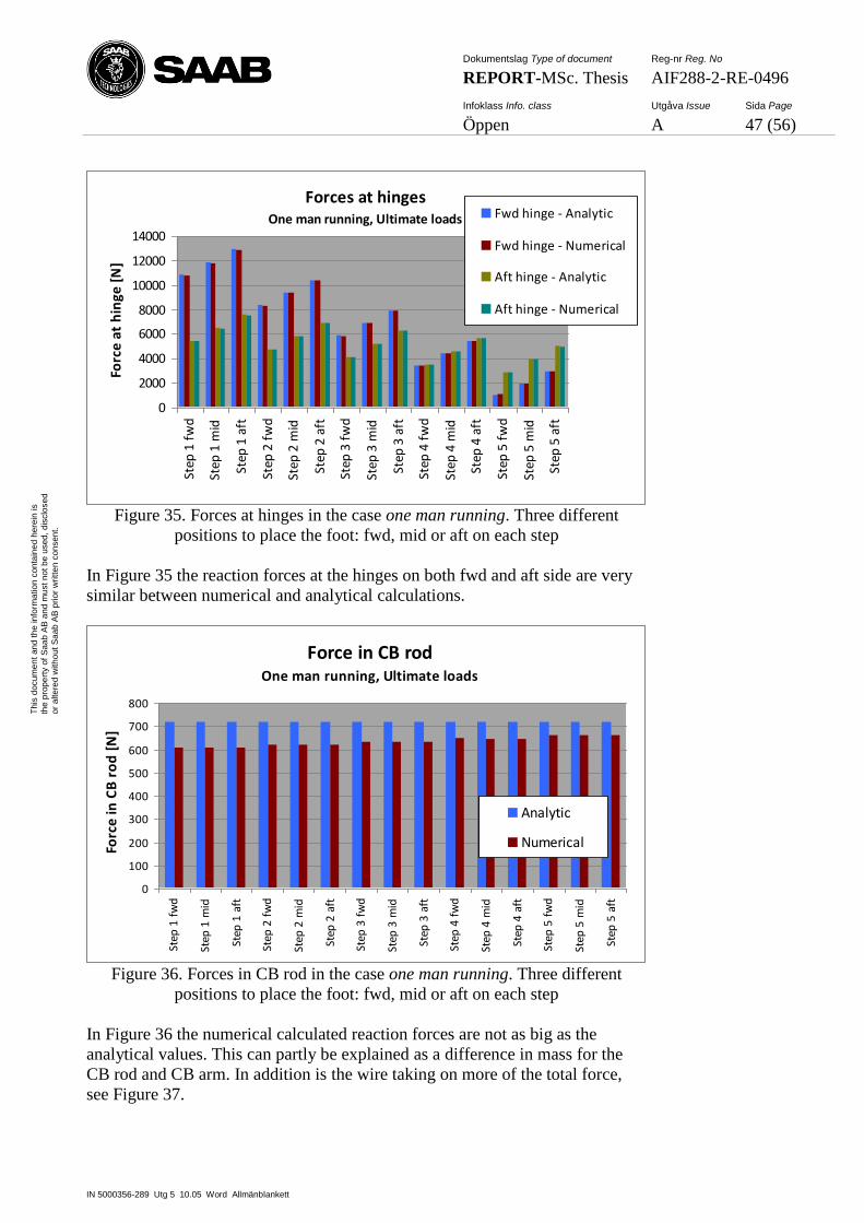
Dokumentslag Type of document Reg-nr Reg. No
REPORT-MSc. Thesis AIF288-2-RE-0496
Infoklass Info. class Utgåva Issue Sida Page
Öppen A 47 (56)
IN 5000356-289 Utg 5 10.05 Word Allmänblankett
Th
is d
ocum
en
t an
d t
he
in
form
atio
n c
on
tain
ed
he
rein
is
the
pro
pe
rty o
f S
aa
b A
B a
nd
mu
st
no
t b
e u
sed
, d
isclo
se
d
or
alte
red
with
ou
t S
aa
b A
B p
rior
wri
tte
n c
on
sen
t.
Forces at hingesOne man running, Ultimate loads
0
2000
4000
6000
8000
10000
12000
14000
Step
1 f
wd
Step
1 m
id
Step
1 a
ft
Step
2 f
wd
Step
2 m
id
Step
2 a
ft
Step
3 f
wd
Step
3 m
id
Step
3 a
ft
Step
4 f
wd
Step
4 m
id
Step
4 a
ft
Step
5 f
wd
Step
5 m
id
Step
5 a
ft
Forc
e at
hin
ge [
N]
Fwd hinge - Analytic
Fwd hinge - Numerical
Aft hinge - Analytic
Aft hinge - Numerical
Figure 35. Forces at hinges in the case one man running. Three different
positions to place the foot: fwd, mid or aft on each step
In Figure 35 the reaction forces at the hinges on both fwd and aft side are very
similar between numerical and analytical calculations.
Force in CB rodOne man running, Ultimate loads
0
100
200
300
400
500
600
700
800
Step
1 f
wd
Step
1 m
id
Step
1 a
ft
Step
2 f
wd
Step
2 m
id
Step
2 a
ft
Step
3 f
wd
Step
3 m
id
Step
3 a
ft
Step
4 f
wd
Step
4 m
id
Step
4 a
ft
Step
5 f
wd
Step
5 m
id
Step
5 a
ft
Forc
e in
CB
ro
d [
N]
Analytic
Numerical
Figure 36. Forces in CB rod in the case one man running. Three different
positions to place the foot: fwd, mid or aft on each step
In Figure 36 the numerical calculated reaction forces are not as big as the
analytical values. This can partly be explained as a difference in mass for the
CB rod and CB arm. In addition is the wire taking on more of the total force,
see Figure 37.
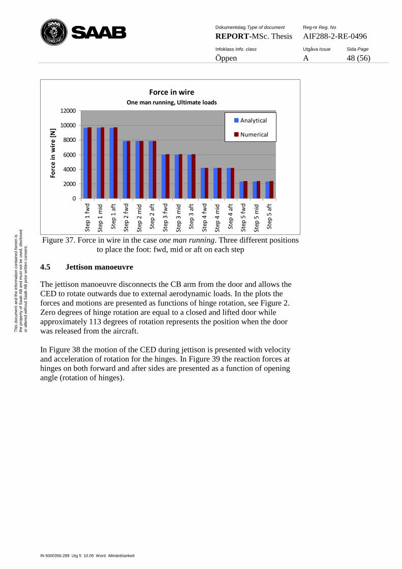
Dokumentslag Type of document Reg-nr Reg. No
REPORT-MSc. Thesis AIF288-2-RE-0496
Infoklass Info. class Utgåva Issue Sida Page
Öppen A 48 (56)
IN 5000356-289 Utg 5 10.05 Word Allmänblankett
Th
is d
ocum
en
t an
d t
he
in
form
atio
n c
on
tain
ed
he
rein
is
the
pro
pe
rty o
f S
aa
b A
B a
nd
mu
st
no
t b
e u
sed
, d
isclo
se
d
or
alte
red
with
ou
t S
aa
b A
B p
rior
wri
tte
n c
on
sen
t.
Force in wireOne man running, Ultimate loads
0
2000
4000
6000
8000
10000
12000
Step
1 f
wd
Step
1 m
id
Step
1 a
ft
Step
2 f
wd
Step
2 m
id
Step
2 a
ft
Step
3 f
wd
Step
3 m
id
Step
3 a
ft
Step
4 f
wd
Step
4 m
id
Step
4 a
ft
Step
5 f
wd
Step
5 m
id
Step
5 a
ft
Forc
e in
wir
e [N
]
Analytical
Numerical
Figure 37. Force in wire in the case one man running. Three different positions
to place the foot: fwd, mid or aft on each step
4.5 Jettison manoeuvre
The jettison manoeuvre disconnects the CB arm from the door and allows the
CED to rotate outwards due to external aerodynamic loads. In the plots the
forces and motions are presented as functions of hinge rotation, see Figure 2.
Zero degrees of hinge rotation are equal to a closed and lifted door while
approximately 113 degrees of rotation represents the position when the door
was released from the aircraft.
In Figure 38 the motion of the CED during jettison is presented with velocity
and acceleration of rotation for the hinges. In Figure 39 the reaction forces at
hinges on both forward and after sides are presented as a function of opening
angle (rotation of hinges).
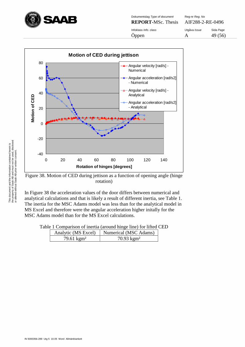
Dokumentslag Type of document Reg-nr Reg. No
REPORT-MSc. Thesis AIF288-2-RE-0496
Infoklass Info. class Utgåva Issue Sida Page
Öppen A 49 (56)
IN 5000356-289 Utg 5 10.05 Word Allmänblankett
Th
is d
ocum
en
t an
d t
he
in
form
atio
n c
on
tain
ed
he
rein
is
the
pro
pe
rty o
f S
aa
b A
B a
nd
mu
st
no
t b
e u
sed
, d
isclo
se
d
or
alte
red
with
ou
t S
aa
b A
B p
rior
wri
tte
n c
on
sen
t.
Motion of CED during jettison
-40
-20
0
20
40
60
80
0 20 40 60 80 100 120 140
Rotation of hinges [degrees]
Mo
tio
n o
f C
ED
Angular velocity [rad/s] -
Numerical
Angular acceleration [rad/s2]
- Numerical
Angular velocity [rad/s] -
Analytical
Angular acceleration [rad/s2]
- Analytical
Figure 38. Motion of CED during jettison as a function of opening angle (hinge
rotation)
In Figure 38 the acceleration values of the door differs between numerical and
analytical calculations and that is likely a result of different inertia, see Table 1.
The inertia for the MSC Adams model was less than for the analytical model in
MS Excel and therefore were the angular acceleration higher initally for the
MSC Adams model than for the MS Excel calculations.
Table 1 Comparison of inertia (around hinge line) for lifted CED
Analytic (MS Excel) Numerical (MSC Adams)
79.61 kgm² 70.93 kgm²
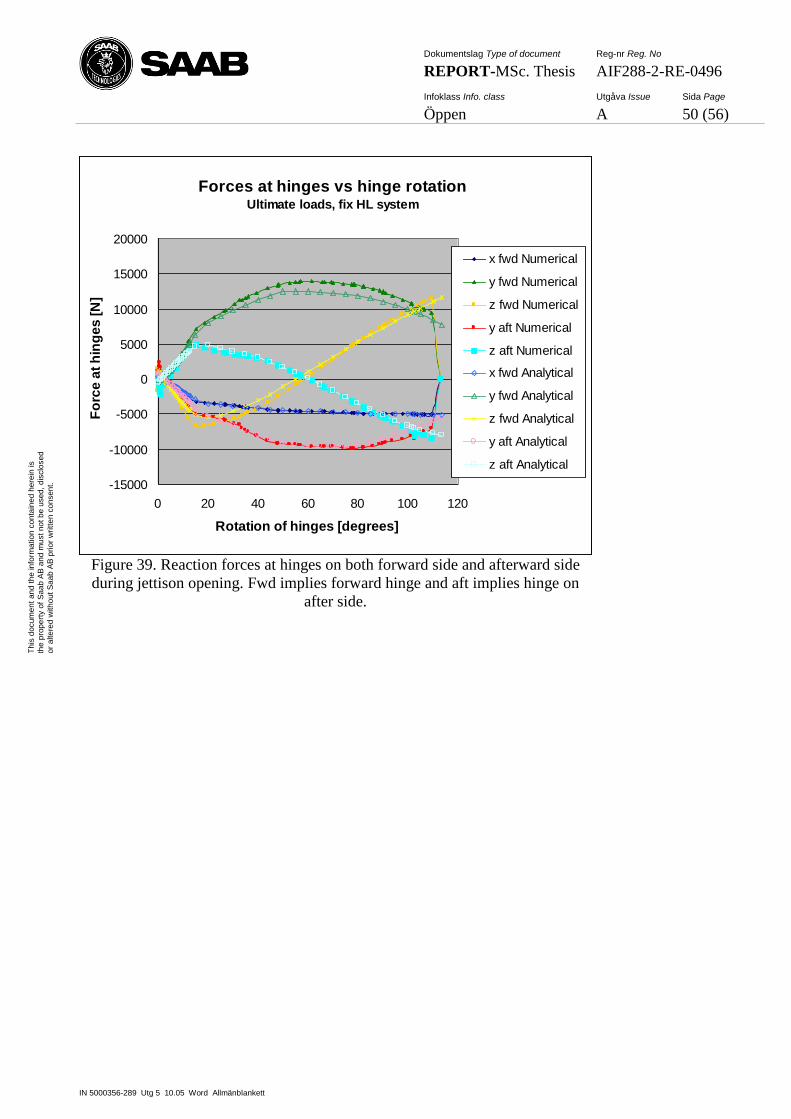
Dokumentslag Type of document Reg-nr Reg. No
REPORT-MSc. Thesis AIF288-2-RE-0496
Infoklass Info. class Utgåva Issue Sida Page
Öppen A 50 (56)
IN 5000356-289 Utg 5 10.05 Word Allmänblankett
Th
is d
ocum
en
t an
d t
he
in
form
atio
n c
on
tain
ed
he
rein
is
the
pro
pe
rty o
f S
aa
b A
B a
nd
mu
st
no
t b
e u
sed
, d
isclo
se
d
or
alte
red
with
ou
t S
aa
b A
B p
rior
wri
tte
n c
on
sen
t.
Forces at hinges vs hinge rotationUltimate loads, fix HL system
-15000
-10000
-5000
0
5000
10000
15000
20000
0 20 40 60 80 100 120
Rotation of hinges [degrees]
Fo
rce
at
hin
ge
s [
N]
x fwd Numerical
y fwd Numerical
z fwd Numerical
y aft Numerical
z aft Numerical
x fwd Analytical
y fwd Analytical
z fwd Analytical
y aft Analytical
z aft Analytical
Figure 39. Reaction forces at hinges on both forward side and afterward side
during jettison opening. Fwd implies forward hinge and aft implies hinge on
after side.
Dokumentslag Type of document Reg-nr Reg. No
REPORT-MSc. Thesis AIF288-2-RE-0496
Infoklass Info. class Utgåva Issue Sida Page
Öppen A 51 (56)
IN 5000356-289 Utg 5 10.05 Word Allmänblankett
Th
is d
ocum
en
t an
d t
he
in
form
atio
n c
on
tain
ed
he
rein
is
the
pro
pe
rty o
f S
aa
b A
B a
nd
mu
st
no
t b
e u
sed
, d
isclo
se
d
or
alte
red
with
ou
t S
aa
b A
B p
rior
wri
tte
n c
on
sen
t.
5 DISCUSSION
In this chapter the results from the different load cases are discussed but also
the use of the Contact function along with mass accuracy and geometry import
are discussed. In addition the question of replacing future MS Excel calculation
with MSC Adams calculations is also discussed.
5.1 Results
In this subchapter the results from different load cases are discussed.
5.1.1 Lifting the door
The difference between dynamic and kinematic models was shown when lifting
without internal pressure. The CED was modelled as a dynamic model to
simplify calculation of motion of the door during jettison. The idea was to get
the dynamic model to be comparable with the analytical calculations by
simulating the manoeuvres with a slow and constant angular velocity for the
bodies in the system. However at lifting without internal pressure the small
radius of the Upper Guide caused a difference between dynamic and kinematic
calculations even though the angular velocity was less than 6 degrees per
second for the rotation of the inner handle. When building these kinds of
models it is therefore important to understand how the choice of model affects
the results.
One advantage with the dynamic model was that it was possible to simulate
what happens with the reaction forces when the handles are let go as soon as the
mechanism could continue the motion by itself. Calculations for lifting with no
negative loads were not possible to do with the kinematic model used in the
analytical calculations. However this kind of simulation was probably more
similar to reality than the other cases. In service it is not likely that the operator
of the door would suddenly change its mind during lifting and start pulling in
the handle with several hundred Newton. In the same way the dynamic model
enables calculations of reaction forces during jettison after that the jettison
mechanism is no longer in contact with the door.
5.1.2 Jamming during lifting manoeuvre
In Figure 31, with the jam in the gearbox, the results from the numerical
calculations were very much alike those from the analytic calculations.
However in Figure 32, with the jam at the outer handle, they differ in two ways.
First of all a sign error in the analytical calculations had caused the numbers for
opening and closing to switch place. Fortunately the numbers were very similar
so it barely affected the results.
The other difference was that in the analytical case the weight of the door was
neglected so therefore would the results differ. However in the same figure,
Figure 32, a simulation with no gravity showed that it was gravity that created
the difference.
Dokumentslag Type of document Reg-nr Reg. No
REPORT-MSc. Thesis AIF288-2-RE-0496
Infoklass Info. class Utgåva Issue Sida Page
Öppen A 52 (56)
IN 5000356-289 Utg 5 10.05 Word Allmänblankett
Th
is d
ocum
en
t an
d t
he
in
form
atio
n c
on
tain
ed
he
rein
is
the
pro
pe
rty o
f S
aa
b A
B a
nd
mu
st
no
t b
e u
sed
, d
isclo
se
d
or
alte
red
with
ou
t S
aa
b A
B p
rior
wri
tte
n c
on
sen
t.
5.1.3 Opened door
For the case with one man running up the stairs, the numerically calculated
values for forces at hinges, see Figure 35, was very similar to the analytical
ones. This description is also accurate for hinge forces for the other cases with
opened door, see appendix A.
However, the forces in CB rod differ between numerical and analytical values.
The same type of results was found for the other load cases, see appendix A.
In the load cases with opened door it is the wire that is taking the external load
while the CB rod is only taking internal load from the CB spring. The
difference is therefore not in how the loads were applied but instead how the
CB mechanism was built and especially mass of the CB arm and rod. In the
opening case it is the CB rod that is taking the external load and in those load
cases the reaction forces were very similar. The reaction forces during opening
are much higher than the forces in the opened cases and therefore can the
difference in the opened case be neglected.
5.1.4 Jettison manoeuvre
In the jettison manoeuvre the difference in inertia, see 5.4, were shown as
differences in angular acceleration, Figure 38. This might also be the reason to
why the reaction forces at hinges differ slightly in Figure 39.
5.2 Use of the Contact function
The Contact function, see chapter 2.2.5, have been used to model a roller
rolling on a cam at Upper Guide, see chapter 3.1.5, but also a contact at Stop1
and the jettison lever contact, see chapter 3.1.5.2.
The Contact with Impact function basically works as when two solids intersect
each other, a spring is created trying to force them apart again. Equilibrium is
reached when the force from the contact spring is equally large and opposite the
force that is trying to push the solids together. However this means that
equilibrium can only be reached when the two solid already has crossed each
other surfaces. In the case with the roller and the cam at Upper Guide this
means that the roller will get a slightly easier way over the top of the cam than
in reality. In Figure 40 this effect is shown with a sketch.
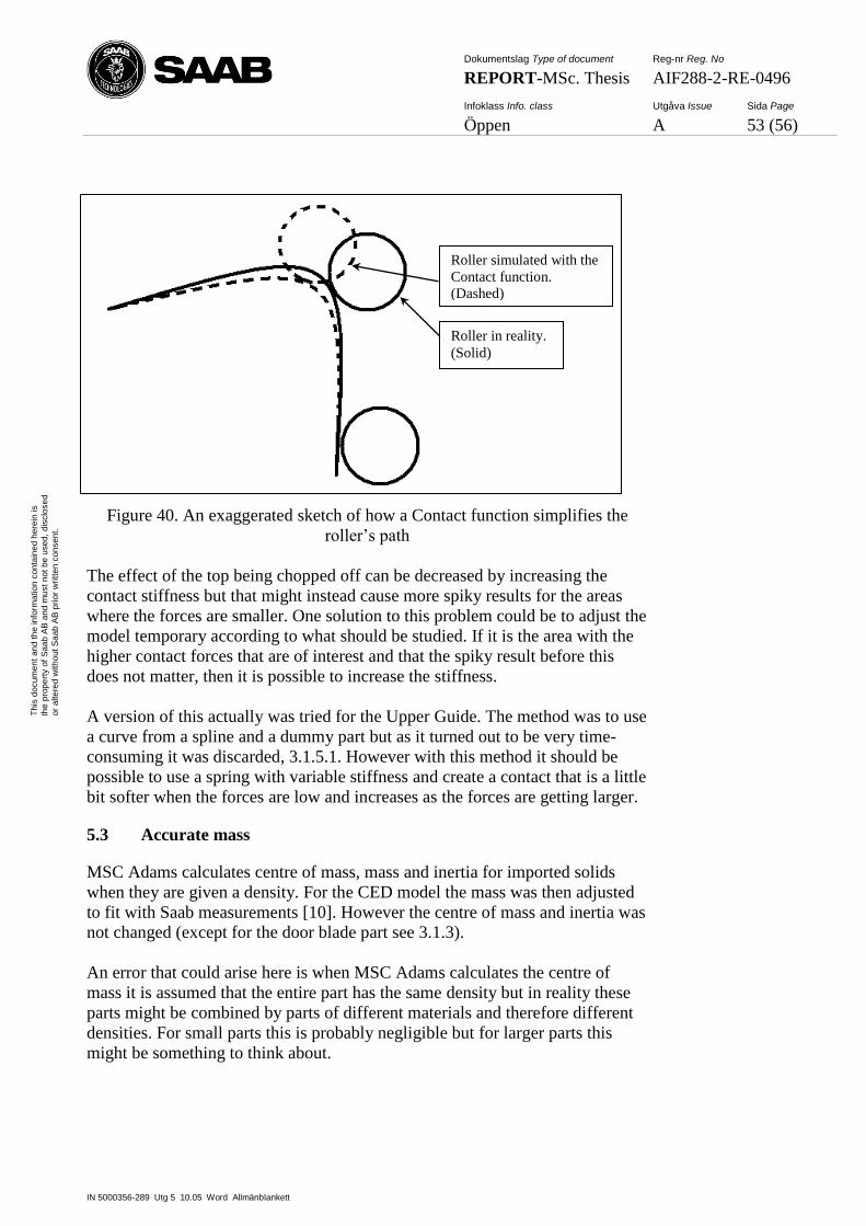
Dokumentslag Type of document Reg-nr Reg. No
REPORT-MSc. Thesis AIF288-2-RE-0496
Infoklass Info. class Utgåva Issue Sida Page
Öppen A 53 (56)
IN 5000356-289 Utg 5 10.05 Word Allmänblankett
Th
is d
ocum
en
t an
d t
he
in
form
atio
n c
on
tain
ed
he
rein
is
the
pro
pe
rty o
f S
aa
b A
B a
nd
mu
st
no
t b
e u
sed
, d
isclo
se
d
or
alte
red
with
ou
t S
aa
b A
B p
rior
wri
tte
n c
on
sen
t.
Figure 40. An exaggerated sketch of how a Contact function simplifies the
roller’s path
The effect of the top being chopped off can be decreased by increasing the
contact stiffness but that might instead cause more spiky results for the areas
where the forces are smaller. One solution to this problem could be to adjust the
model temporary according to what should be studied. If it is the area with the
higher contact forces that are of interest and that the spiky result before this
does not matter, then it is possible to increase the stiffness.
A version of this actually was tried for the Upper Guide. The method was to use
a curve from a spline and a dummy part but as it turned out to be very time-
consuming it was discarded, 3.1.5.1. However with this method it should be
possible to use a spring with variable stiffness and create a contact that is a little
bit softer when the forces are low and increases as the forces are getting larger.
5.3 Accurate mass
MSC Adams calculates centre of mass, mass and inertia for imported solids
when they are given a density. For the CED model the mass was then adjusted
to fit with Saab measurements [10]. However the centre of mass and inertia was
not changed (except for the door blade part see 3.1.3).
An error that could arise here is when MSC Adams calculates the centre of
mass it is assumed that the entire part has the same density but in reality these
parts might be combined by parts of different materials and therefore different
densities. For small parts this is probably negligible but for larger parts this
might be something to think about.
Roller in reality.
(Solid)
Roller simulated with the
Contact function.
(Dashed)

Dokumentslag Type of document Reg-nr Reg. No
REPORT-MSc. Thesis AIF288-2-RE-0496
Infoklass Info. class Utgåva Issue Sida Page
Öppen A 54 (56)
IN 5000356-289 Utg 5 10.05 Word Allmänblankett
Th
is d
ocum
en
t an
d t
he
in
form
atio
n c
on
tain
ed
he
rein
is
the
pro
pe
rty o
f S
aa
b A
B a
nd
mu
st
no
t b
e u
sed
, d
isclo
se
d
or
alte
red
with
ou
t S
aa
b A
B p
rior
wri
tte
n c
on
sen
t.
5.4 Importing CAD geometry
Some geometry got imported as sheet-bodies instead of solids, see 3.1.2. One
difference between sheet-bodies and solids is that sheet bodies are not given
any mass, centre of mass or inertia when given a density. The effect of some
parts not having correct inertia was shown in simulations such as jettison
manoeuvre.
The reason why some geometry is imported as sheet-bodies is that they contain
a hole somewhere on the surface. There exist software that can repair damaged
parts and turn sheet-bodies into solids, for example Rhinoceros [6] and Ansa
[7].
5.5 Replacing MS Excel with MSC Adams
The benefit of working with MSC Adams instead of MS Excel is that it is
quicker and more user friendly. In addition, MSC Adams provides an extra
immediate checking feature by animating the movement of the parts. Many of
the built-in errors in the model configuration are therefore easily found and
corrected.
Apart from calculating reaction forces and motions, MS Excel has been used to
select critical values from the calculations and creating critical envelopes to use
when sizing parts in the mechanical system. These post-simulation calculations
seem not to be suitable to conduct in MSC Adams. They and other post
calculations are in the Authors opinion probably best to keep doing in MS
Excel. Results can be exported from MSC Adams in several ways, for example
as tables that can be copy into MS Excel.
Another calculation that was made analytically in MS Excel was to calculate
the bending moment of shafts at particular locations, for example if a there was
a hole for a bolt. These bending moments can be calculated with the MSC
Adams model by splitting the shaft in two (at the location of the hole) and
placing out a fix joint that connects both sides of the shaft. Then the bending
moment could be measured during simulation and presented in a coordinate
system that follows the shaft in its rotation.
In addition, when starting a new project it must be able to bring the computer
with software to another location, perhaps even to another country for a few
months. This set demands on software licenses that can be mobile. According to
a software specialist1 at Saab the MCS Adams licenses will not be a problem.
1 Krus, Jonatan, [email protected], OOIDCA
Dokumentslag Type of document Reg-nr Reg. No
REPORT-MSc. Thesis AIF288-2-RE-0496
Infoklass Info. class Utgåva Issue Sida Page
Öppen A 55 (56)
IN 5000356-289 Utg 5 10.05 Word Allmänblankett
Th
is d
ocum
en
t an
d t
he
in
form
atio
n c
on
tain
ed
he
rein
is
the
pro
pe
rty o
f S
aa
b A
B a
nd
mu
st
no
t b
e u
sed
, d
isclo
se
d
or
alte
red
with
ou
t S
aa
b A
B p
rior
wri
tte
n c
on
sen
t.
6 CONCLUSION AND FUTURE WORK
Creating a model of a mechanical system in MSC Adams/View is easy and
fairly quick. The benefit of working with MSC Adams instead of MS Excel is
that it is quicker and more user friendly.
It is in the Authors opinion that for future projects, the analytical method with
MS Excel to calculate reaction forces and motions of the CED can and should
be replaced by numerical calculations with MSC Adams/View. The major
differences in results between the two methods are believed to be an effect by
comparing results from a kinematic model with results from a dynamic model
and therefore not an effect of comparing analytical and numerical calculated
values.
However, apart from calculating reaction forces there are additional post-
simulation calculations for which it is perhaps more beneficial to use MS Excel.
This is not a problem since MSC Adams can export results efficiently.
If Saab Aerostructures decides to start working with MSC Adams/View and if
Saab wants geometry to be imported to the model, then a strong advise from the
Author is to have a software installed that can convert step-files (*.stp or *.step)
to the MSC Adams preferred file format Parasolid (*.xmt_txt or *.x_t). The
software should also be able to repair geometry which will greatly increase
mass accuracy.
A few things that can be continued to work with on this model are the contact
on the Upper Guide and the releasing mechanism of the hinges during jettison.
In addition, repairs of parts that have been imported as sheet-bodies can be
conducted and thereby giving a more correct inertia to the model.
Dokumentslag Type of document Reg-nr Reg. No
REPORT-MSc. Thesis AIF288-2-RE-0496
Infoklass Info. class Utgåva Issue Sida Page
Öppen A 56 (56)
IN 5000356-289 Utg 5 10.05 Word Allmänblankett
Th
is d
ocum
en
t an
d t
he
in
form
atio
n c
on
tain
ed
he
rein
is
the
pro
pe
rty o
f S
aa
b A
B a
nd
mu
st
no
t b
e u
sed
, d
isclo
se
d
or
alte
red
with
ou
t S
aa
b A
B p
rior
wri
tte
n c
on
sen
t.
7 REFERENCES
[1] Airbus Military, http://www.airbusmilitary.com, [cited: 120426]
[2] Hoyle, Craig (2011). A400m on track for early 2013 delivery says airbus.
Flight global, http://www.flightglobal.com/news/articles/a400m-on-track-
for-early-2013-delivery-says-airbus-356937/, [cited: 120426]
[3] Christensen, Peter ( ). Computational Rigid Body Mechanics, Division of
Mechanics - University of Linkoping, Unpublished course material for the
course Robotics and Multibody Dynamics
[4] MSC Adams, MSC Adams/View help – 2012
[5] MSC Adams, MSC Adams Solver help – 2012
[6] McNeel, Rhinoceros Inc –,
Webpage: http://www.rhino3d.com/, [cited: 120503]
[7] BETA CAE Systems S.A, Ansa –
Webpage: http://www.beta-cae.gr/ansa.htm, [cited: 120503]
Saab internal reports:
[8] Saab AB, A400M Crew Entrance Door – Load analysis for jettison –
AIF288-2-RE-0017 issue: F, Internal report
[9] Saab AB, A400M Crew Entrance Door – External airloads and movement
during jettison – AIF288-2-RE-0122 issue: B, Internal report
[10] Saab AB, A400M CED. Mass data for MSC Adams model – AIF288-2-
PM-0064 issue: B, Company restricted
[11] Saab AB, Door CounterBalance Mechanism, Static Justification report–
112502-M021BRP101291, Company restricted
[12] Saab AB, A400M Crew Entrance Door – Calculation of handle and
interface loads for door opening – AIF288-2-RE-0099 issue: D, internal
report
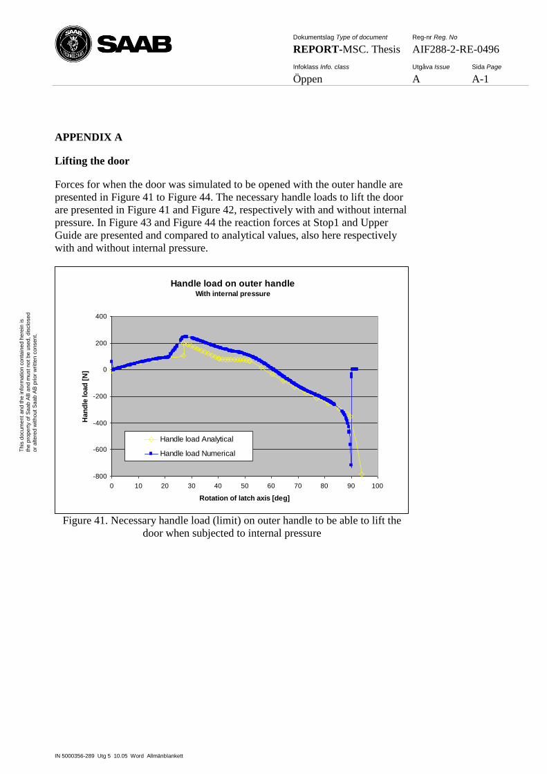
Dokumentslag Type of document Reg-nr Reg. No
REPORT-MSC. Thesis AIF288-2-RE-0496
Infoklass Info. class Utgåva Issue Sida Page
Öppen A A-1
IN 5000356-289 Utg 5 10.05 Word Allmänblankett
Th
is d
ocum
en
t an
d t
he
in
form
atio
n c
on
tain
ed
he
rein
is
the
pro
pe
rty o
f S
aa
b A
B a
nd
mu
st
no
t b
e u
sed
, d
isclo
se
d
or
alte
red
with
ou
t S
aa
b A
B p
rior
wri
tte
n c
on
sen
t.
APPENDIX A
Lifting the door
Forces for when the door was simulated to be opened with the outer handle are
presented in Figure 41 to Figure 44. The necessary handle loads to lift the door
are presented in Figure 41 and Figure 42, respectively with and without internal
pressure. In Figure 43 and Figure 44 the reaction forces at Stop1 and Upper
Guide are presented and compared to analytical values, also here respectively
with and without internal pressure.
Handle load on outer handleWith internal pressure
-800
-600
-400
-200
0
200
400
0 10 20 30 40 50 60 70 80 90 100
Rotation of latch axis [deg]
Han
dle
lo
ad
[N
]
Handle load Analytical
Handle load Numerical
Figure 41. Necessary handle load (limit) on outer handle to be able to lift the
door when subjected to internal pressure
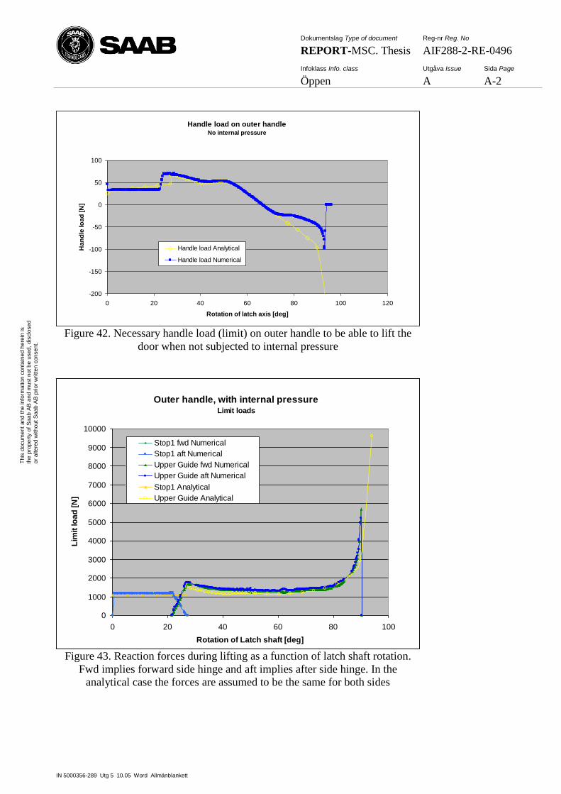
Dokumentslag Type of document Reg-nr Reg. No
REPORT-MSC. Thesis AIF288-2-RE-0496
Infoklass Info. class Utgåva Issue Sida Page
Öppen A A-2
IN 5000356-289 Utg 5 10.05 Word Allmänblankett
Th
is d
ocum
en
t an
d t
he
in
form
atio
n c
on
tain
ed
he
rein
is
the
pro
pe
rty o
f S
aa
b A
B a
nd
mu
st
no
t b
e u
sed
, d
isclo
se
d
or
alte
red
with
ou
t S
aa
b A
B p
rior
wri
tte
n c
on
sen
t.
Handle load on outer handleNo internal pressure
-200
-150
-100
-50
0
50
100
0 20 40 60 80 100 120
Rotation of latch axis [deg]
Ha
nd
le lo
ad
[N
]
Handle load Analytical
Handle load Numerical
Figure 42. Necessary handle load (limit) on outer handle to be able to lift the
door when not subjected to internal pressure
Outer handle, with internal pressureLimit loads
0
1000
2000
3000
4000
5000
6000
7000
8000
9000
10000
0 20 40 60 80 100
Rotation of Latch shaft [deg]
Lim
it lo
ad
[N
]
Stop1 fwd Numerical
Stop1 aft Numerical
Upper Guide fwd Numerical
Upper Guide aft Numerical
Stop1 Analytical
Upper Guide Analytical
Figure 43. Reaction forces during lifting as a function of latch shaft rotation.
Fwd implies forward side hinge and aft implies after side hinge. In the
analytical case the forces are assumed to be the same for both sides
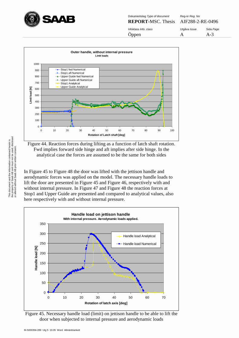
Dokumentslag Type of document Reg-nr Reg. No
REPORT-MSC. Thesis AIF288-2-RE-0496
Infoklass Info. class Utgåva Issue Sida Page
Öppen A A-3
IN 5000356-289 Utg 5 10.05 Word Allmänblankett
Th
is d
ocum
en
t an
d t
he
in
form
atio
n c
on
tain
ed
he
rein
is
the
pro
pe
rty o
f S
aa
b A
B a
nd
mu
st
no
t b
e u
sed
, d
isclo
se
d
or
alte
red
with
ou
t S
aa
b A
B p
rior
wri
tte
n c
on
sen
t.
Outer handle, without internal pressureLimit loads
0
100
200
300
400
500
600
700
800
900
1000
0 10 20 30 40 50 60 70 80 90 100
Rotation of Latch shaft [deg]
Lim
it lo
ad
[N
]
Stop1 fwd Numerical
Stop1 aft Numerical
Upper Guide fwd Numerical
Upper Guide aft Numerical
Stop1 Analytical
Upper Guide Analytical
Figure 44. Reaction forces during lifting as a function of latch shaft rotation.
Fwd implies forward side hinge and aft implies after side hinge. In the
analytical case the forces are assumed to be the same for both sides
In Figure 45 to Figure 48 the door was lifted with the jettison handle and
aerodynamic forces was applied on the model. The necessary handle loads to
lift the door are presented in Figure 45 and Figure 46, respectively with and
without internal pressure. In Figure 47 and Figure 48 the reaction forces at
Stop1 and Upper Guide are presented and compared to analytical values, also
here respectively with and without internal pressure.
Handle load on jettison handleWith internal pressure. Aerodynamic loads applied.
0
50
100
150
200
250
300
350
0 10 20 30 40 50 60 70
Rotation of latch axis [deg]
Ha
nd
le lo
ad
[N
]
Handle load Analytical
Handle load Numerical
Figure 45. Necessary handle load (limit) on jettison handle to be able to lift the
door when subjected to internal pressure and aerodynamic loads
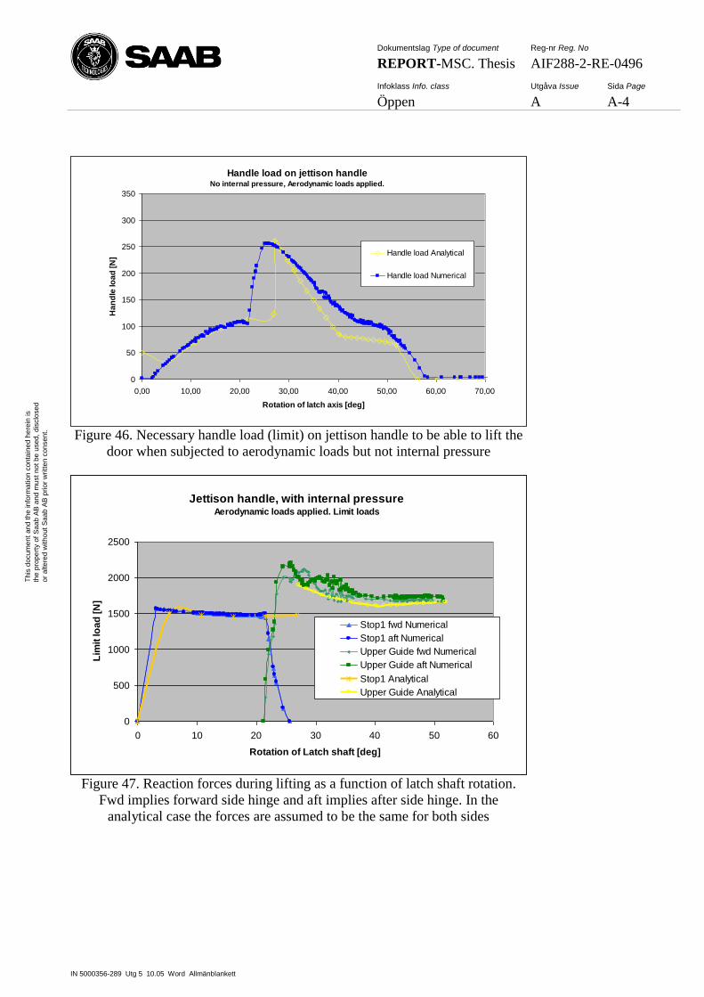
Dokumentslag Type of document Reg-nr Reg. No
REPORT-MSC. Thesis AIF288-2-RE-0496
Infoklass Info. class Utgåva Issue Sida Page
Öppen A A-4
IN 5000356-289 Utg 5 10.05 Word Allmänblankett
Th
is d
ocum
en
t an
d t
he
in
form
atio
n c
on
tain
ed
he
rein
is
the
pro
pe
rty o
f S
aa
b A
B a
nd
mu
st
no
t b
e u
sed
, d
isclo
se
d
or
alte
red
with
ou
t S
aa
b A
B p
rior
wri
tte
n c
on
sen
t.
Handle load on jettison handleNo internal pressure, Aerodynamic loads applied.
0
50
100
150
200
250
300
350
0,00 10,00 20,00 30,00 40,00 50,00 60,00 70,00
Rotation of latch axis [deg]
Ha
nd
le lo
ad
[N
]
Handle load Analytical
Handle load Numerical
Figure 46. Necessary handle load (limit) on jettison handle to be able to lift the
door when subjected to aerodynamic loads but not internal pressure
Jettison handle, with internal pressureAerodynamic loads applied. Limit loads
0
500
1000
1500
2000
2500
0 10 20 30 40 50 60
Rotation of Latch shaft [deg]
Lim
it lo
ad
[N
]
Stop1 fwd Numerical
Stop1 aft Numerical
Upper Guide fwd Numerical
Upper Guide aft Numerical
Stop1 Analytical
Upper Guide Analytical
Figure 47. Reaction forces during lifting as a function of latch shaft rotation.
Fwd implies forward side hinge and aft implies after side hinge. In the
analytical case the forces are assumed to be the same for both sides
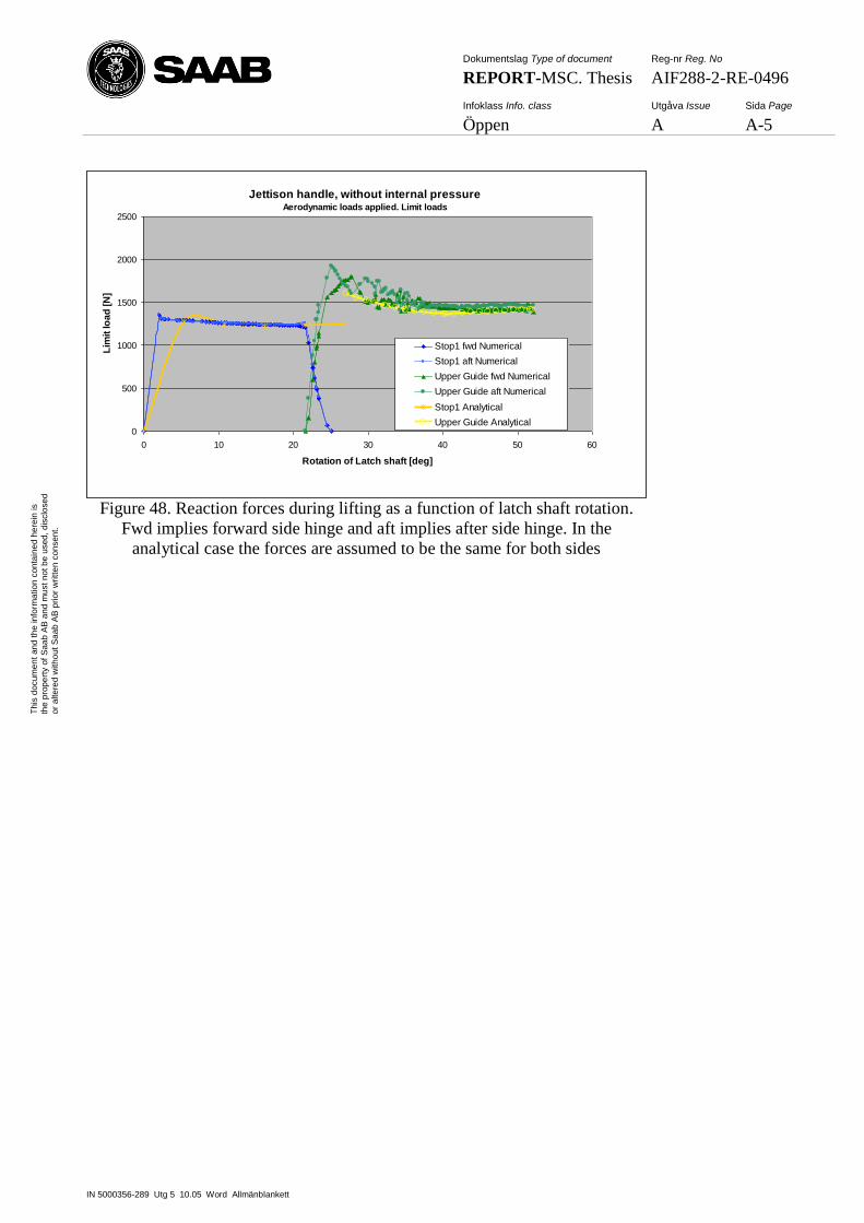
Dokumentslag Type of document Reg-nr Reg. No
REPORT-MSC. Thesis AIF288-2-RE-0496
Infoklass Info. class Utgåva Issue Sida Page
Öppen A A-5
IN 5000356-289 Utg 5 10.05 Word Allmänblankett
Th
is d
ocum
en
t an
d t
he
in
form
atio
n c
on
tain
ed
he
rein
is
the
pro
pe
rty o
f S
aa
b A
B a
nd
mu
st
no
t b
e u
sed
, d
isclo
se
d
or
alte
red
with
ou
t S
aa
b A
B p
rior
wri
tte
n c
on
sen
t.
Jettison handle, without internal pressureAerodynamic loads applied. Limit loads
0
500
1000
1500
2000
2500
0 10 20 30 40 50 60
Rotation of Latch shaft [deg]
Lim
it lo
ad
[N
]
Stop1 fwd Numerical
Stop1 aft Numerical
Upper Guide fwd Numerical
Upper Guide aft Numerical
Stop1 Analytical
Upper Guide Analytical
Figure 48. Reaction forces during lifting as a function of latch shaft rotation.
Fwd implies forward side hinge and aft implies after side hinge. In the
analytical case the forces are assumed to be the same for both sides
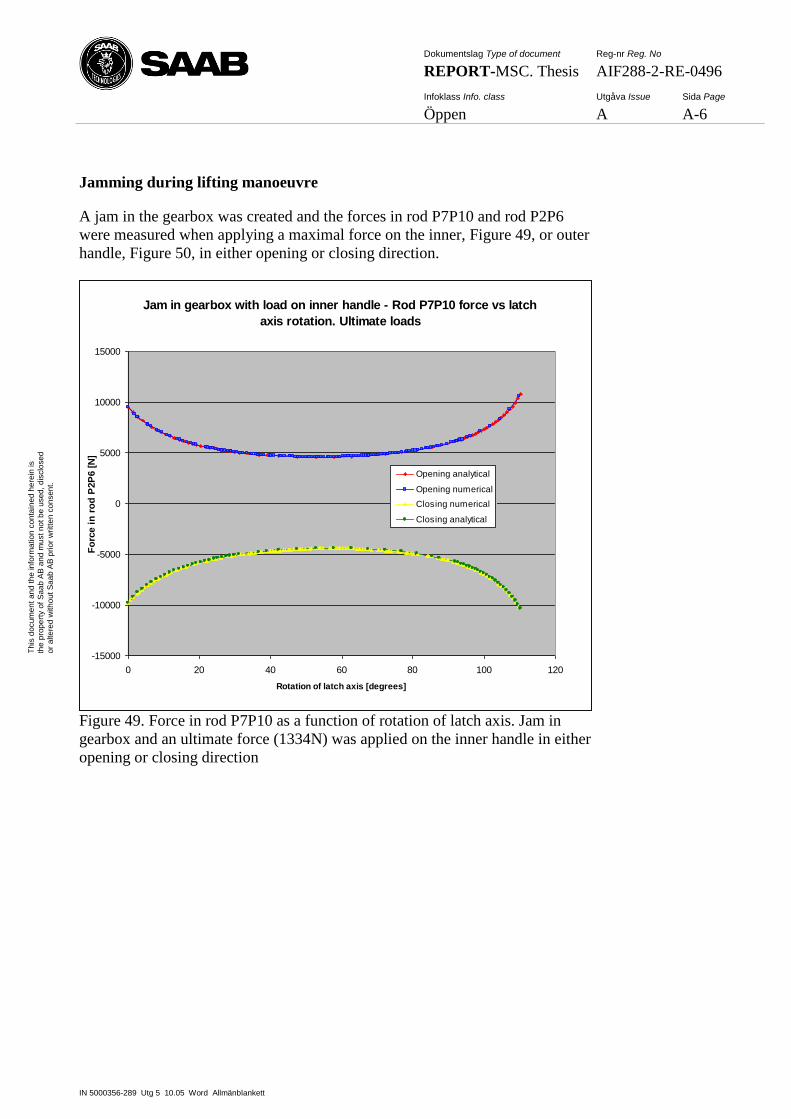
Dokumentslag Type of document Reg-nr Reg. No
REPORT-MSC. Thesis AIF288-2-RE-0496
Infoklass Info. class Utgåva Issue Sida Page
Öppen A A-6
IN 5000356-289 Utg 5 10.05 Word Allmänblankett
Th
is d
ocum
en
t an
d t
he
in
form
atio
n c
on
tain
ed
he
rein
is
the
pro
pe
rty o
f S
aa
b A
B a
nd
mu
st
no
t b
e u
sed
, d
isclo
se
d
or
alte
red
with
ou
t S
aa
b A
B p
rior
wri
tte
n c
on
sen
t.
Jamming during lifting manoeuvre
A jam in the gearbox was created and the forces in rod P7P10 and rod P2P6
were measured when applying a maximal force on the inner, Figure 49, or outer
handle, Figure 50, in either opening or closing direction.
Jam in gearbox with load on inner handle - Rod P7P10 force vs latch
axis rotation. Ultimate loads
-15000
-10000
-5000
0
5000
10000
15000
0 20 40 60 80 100 120
Rotation of latch axis [degrees]
Fo
rce i
n r
od
P2P
6 [
N]
Opening analytical
Opening numerical
Closing numerical
Closing analytical
Figure 49. Force in rod P7P10 as a function of rotation of latch axis. Jam in
gearbox and an ultimate force (1334N) was applied on the inner handle in either
opening or closing direction
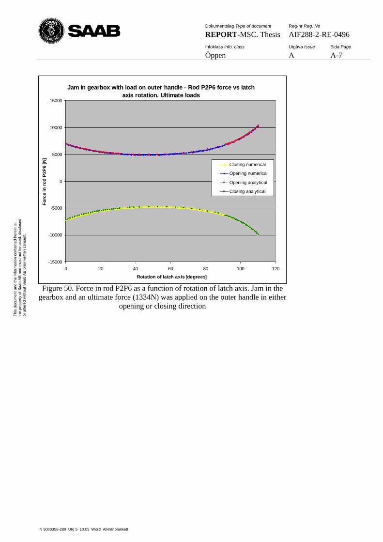
Dokumentslag Type of document Reg-nr Reg. No
REPORT-MSC. Thesis AIF288-2-RE-0496
Infoklass Info. class Utgåva Issue Sida Page
Öppen A A-7
IN 5000356-289 Utg 5 10.05 Word Allmänblankett
Th
is d
ocum
en
t an
d t
he
in
form
atio
n c
on
tain
ed
he
rein
is
the
pro
pe
rty o
f S
aa
b A
B a
nd
mu
st
no
t b
e u
sed
, d
isclo
se
d
or
alte
red
with
ou
t S
aa
b A
B p
rior
wri
tte
n c
on
sen
t.
Jam in gearbox with load on outer handle - Rod P2P6 force vs latch
axis rotation. Ultimate loads
-15000
-10000
-5000
0
5000
10000
15000
0 20 40 60 80 100 120
Rotation of latch axis [degrees]
Fo
rce i
n r
od
P2P
6 [
N]
Closing numerical
Opening numerical
Opening analytical
Closing analytical
Figure 50. Force in rod P2P6 as a function of rotation of latch axis. Jam in the
gearbox and an ultimate force (1334N) was applied on the outer handle in either
opening or closing direction
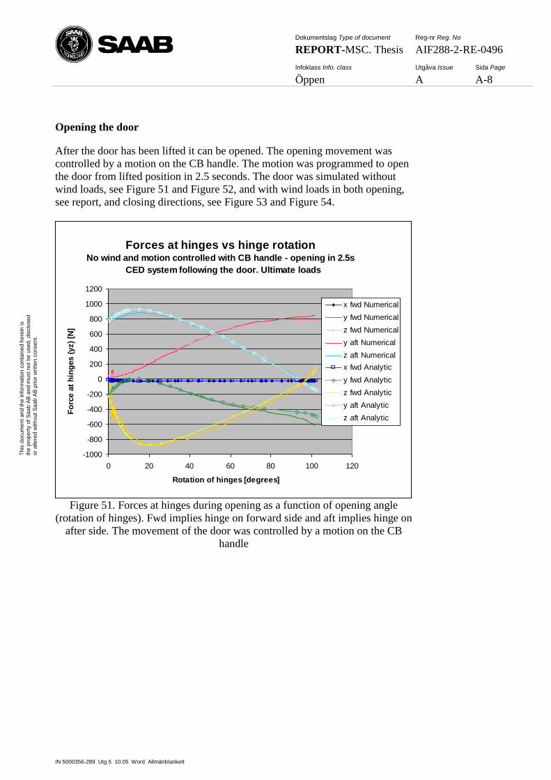
Dokumentslag Type of document Reg-nr Reg. No
REPORT-MSC. Thesis AIF288-2-RE-0496
Infoklass Info. class Utgåva Issue Sida Page
Öppen A A-8
IN 5000356-289 Utg 5 10.05 Word Allmänblankett
Th
is d
ocum
en
t an
d t
he
in
form
atio
n c
on
tain
ed
he
rein
is
the
pro
pe
rty o
f S
aa
b A
B a
nd
mu
st
no
t b
e u
sed
, d
isclo
se
d
or
alte
red
with
ou
t S
aa
b A
B p
rior
wri
tte
n c
on
sen
t.
Opening the door
After the door has been lifted it can be opened. The opening movement was
controlled by a motion on the CB handle. The motion was programmed to open
the door from lifted position in 2.5 seconds. The door was simulated without
wind loads, see Figure 51 and Figure 52, and with wind loads in both opening,
see report, and closing directions, see Figure 53 and Figure 54.
Forces at hinges vs hinge rotationNo wind and motion controlled with CB handle - opening in 2.5s
CED system following the door. Ultimate loads
-1000
-800
-600
-400
-200
0
200
400
600
800
1000
1200
0 20 40 60 80 100 120
Rotation of hinges [degrees]
Fo
rce a
t h
ing
es (
yz)
[N]
x fwd Numerical
y fwd Numerical
z fwd Numerical
y aft Numerical
z aft Numerical
x fwd Analytic
y fwd Analytic
z fwd Analytic
y aft Analytic
z aft Analytic
Figure 51. Forces at hinges during opening as a function of opening angle
(rotation of hinges). Fwd implies hinge on forward side and aft implies hinge on
after side. The movement of the door was controlled by a motion on the CB
handle
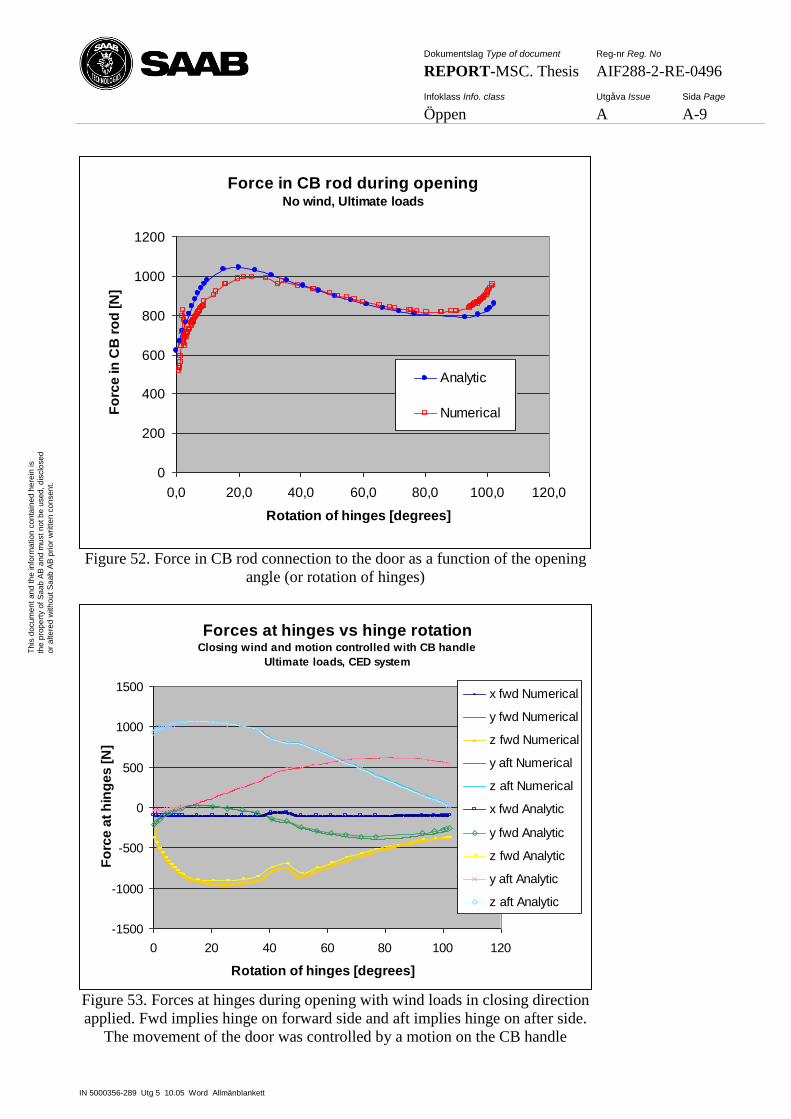
Dokumentslag Type of document Reg-nr Reg. No
REPORT-MSC. Thesis AIF288-2-RE-0496
Infoklass Info. class Utgåva Issue Sida Page
Öppen A A-9
IN 5000356-289 Utg 5 10.05 Word Allmänblankett
Th
is d
ocum
en
t an
d t
he
in
form
atio
n c
on
tain
ed
he
rein
is
the
pro
pe
rty o
f S
aa
b A
B a
nd
mu
st
no
t b
e u
sed
, d
isclo
se
d
or
alte
red
with
ou
t S
aa
b A
B p
rior
wri
tte
n c
on
sen
t.
Force in CB rod during openingNo wind, Ultimate loads
0
200
400
600
800
1000
1200
0,0 20,0 40,0 60,0 80,0 100,0 120,0
Rotation of hinges [degrees]
Fo
rce
in
CB
ro
d [
N]
Analytic
Numerical
Figure 52. Force in CB rod connection to the door as a function of the opening
angle (or rotation of hinges)
Forces at hinges vs hinge rotationClosing wind and motion controlled with CB handle
Ultimate loads, CED system
-1500
-1000
-500
0
500
1000
1500
0 20 40 60 80 100 120
Rotation of hinges [degrees]
Fo
rce
at
hin
ge
s [
N]
x fwd Numerical
y fwd Numerical
z fwd Numerical
y aft Numerical
z aft Numerical
x fwd Analytic
y fwd Analytic
z fwd Analytic
y aft Analytic
z aft Analytic
Figure 53. Forces at hinges during opening with wind loads in closing direction
applied. Fwd implies hinge on forward side and aft implies hinge on after side.
The movement of the door was controlled by a motion on the CB handle
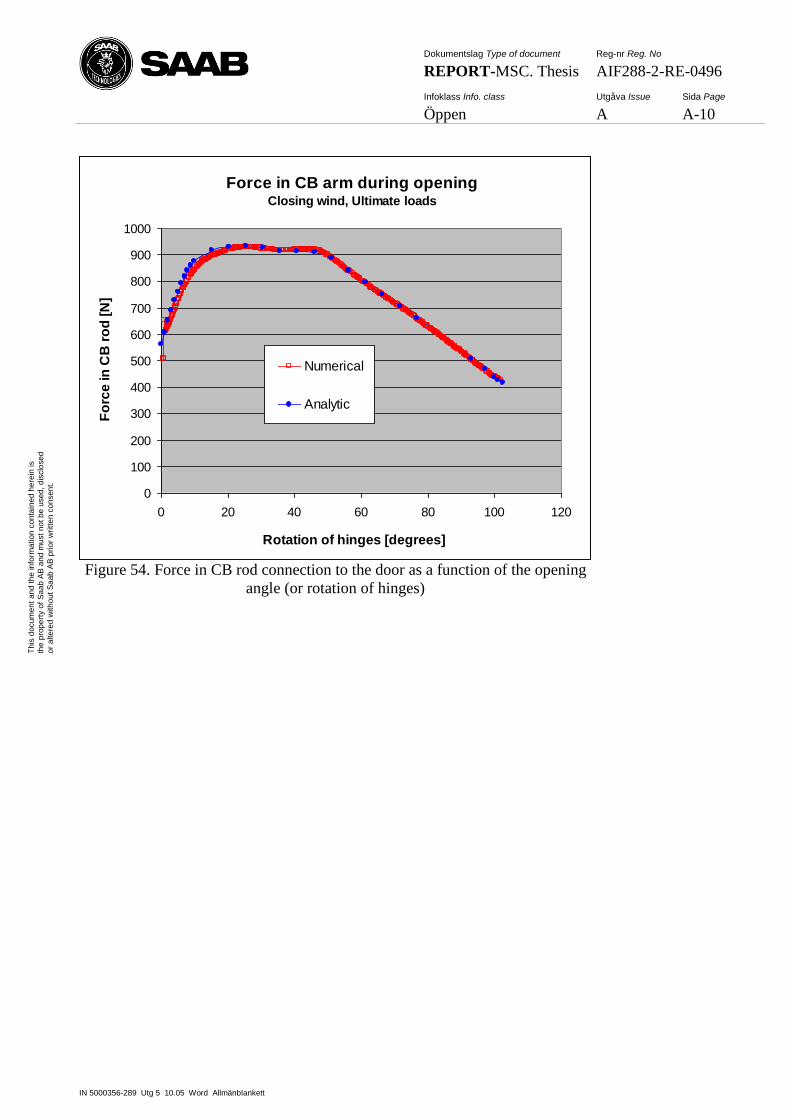
Dokumentslag Type of document Reg-nr Reg. No
REPORT-MSC. Thesis AIF288-2-RE-0496
Infoklass Info. class Utgåva Issue Sida Page
Öppen A A-10
IN 5000356-289 Utg 5 10.05 Word Allmänblankett
Th
is d
ocum
en
t an
d t
he
in
form
atio
n c
on
tain
ed
he
rein
is
the
pro
pe
rty o
f S
aa
b A
B a
nd
mu
st
no
t b
e u
sed
, d
isclo
se
d
or
alte
red
with
ou
t S
aa
b A
B p
rior
wri
tte
n c
on
sen
t.
Force in CB arm during openingClosing wind, Ultimate loads
0
100
200
300
400
500
600
700
800
900
1000
0 20 40 60 80 100 120
Rotation of hinges [degrees]
Fo
rce
in
CB
ro
d [
N]
Numerical
Analytic
Figure 54. Force in CB rod connection to the door as a function of the opening
angle (or rotation of hinges)
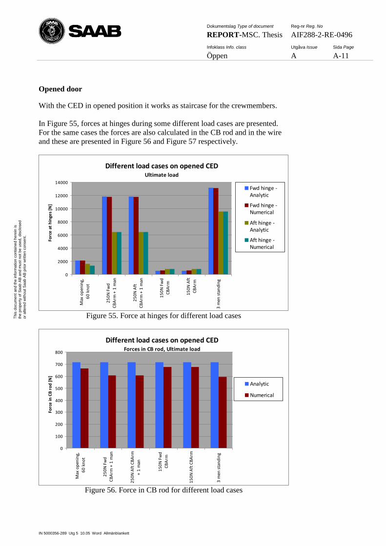
Dokumentslag Type of document Reg-nr Reg. No
REPORT-MSC. Thesis AIF288-2-RE-0496
Infoklass Info. class Utgåva Issue Sida Page
Öppen A A-11
IN 5000356-289 Utg 5 10.05 Word Allmänblankett
Th
is d
ocum
en
t an
d t
he
in
form
atio
n c
on
tain
ed
he
rein
is
the
pro
pe
rty o
f S
aa
b A
B a
nd
mu
st
no
t b
e u
sed
, d
isclo
se
d
or
alte
red
with
ou
t S
aa
b A
B p
rior
wri
tte
n c
on
sen
t.
Opened door
With the CED in opened position it works as staircase for the crewmembers.
In Figure 55, forces at hinges during some different load cases are presented.
For the same cases the forces are also calculated in the CB rod and in the wire
and these are presented in Figure 56 and Figure 57 respectively.
Different load cases on opened CEDUltimate load
0
2000
4000
6000
8000
10000
12000
14000
Max
op
enin
g,
60
kn
ot
25
0N
Fw
d
CB
Arm
+ 1
man
25
0N
Aft
CB
Arm
+ 1
man
15
0N
Fw
d
CB
Arm
15
0N
Aft
CB
Arm
3 m
en s
tan
din
g
Forc
e a
t h
inge
s [N
]
Fwd hinge -Analytic
Fwd hinge -Numerical
Aft hinge -Analytic
Aft hinge -Numerical
Figure 55. Force at hinges for different load cases
Different load cases on opened CEDForces in CB rod, Ultimate load
0
100
200
300
400
500
600
700
800
Max
op
enin
g,
60
kn
ot
25
0N
Fw
d
CB
Arm
+ 1
man
25
0N
Aft
CB
Arm
+ 1
man
15
0N
Fw
d
CB
Arm
15
0N
Aft
CB
Arm
3 m
en s
tan
din
g
Forc
e in
CB
ro
d [
N]
Analytic
Numerical
Figure 56. Force in CB rod for different load cases
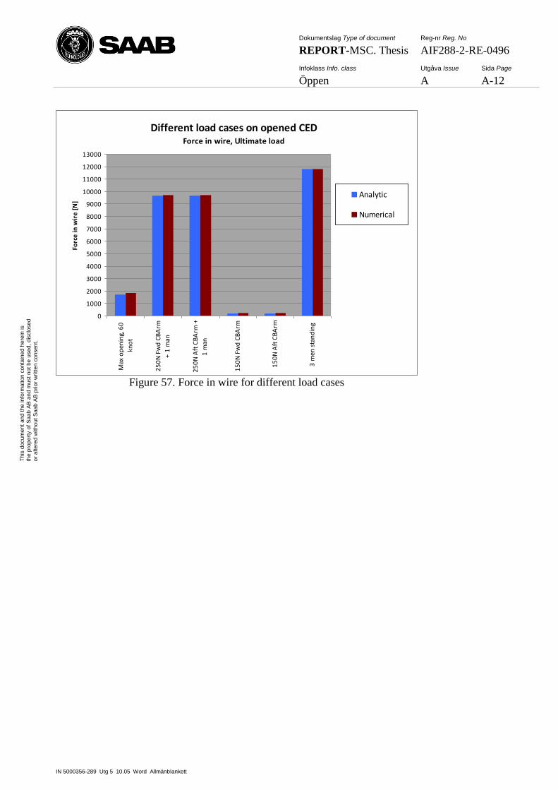
Dokumentslag Type of document Reg-nr Reg. No
REPORT-MSC. Thesis AIF288-2-RE-0496
Infoklass Info. class Utgåva Issue Sida Page
Öppen A A-12
IN 5000356-289 Utg 5 10.05 Word Allmänblankett
Th
is d
ocum
en
t an
d t
he
in
form
atio
n c
on
tain
ed
he
rein
is
the
pro
pe
rty o
f S
aa
b A
B a
nd
mu
st
no
t b
e u
sed
, d
isclo
se
d
or
alte
red
with
ou
t S
aa
b A
B p
rior
wri
tte
n c
on
sen
t.
Different load cases on opened CEDForce in wire, Ultimate load
0
1000
2000
3000
4000
5000
6000
7000
8000
9000
10000
11000
12000
13000
Max
op
enin
g, 6
0
kno
t
25
0N
Fw
d C
BA
rm
+ 1
man
25
0N
Aft
CB
Arm
+
1 m
an
15
0N
Fw
d C
BA
rm
15
0N
Aft
CB
Arm
3 m
en s
tan
din
g
Forc
e in
wir
e [
N]
Analytic
Numerical
Figure 57. Force in wire for different load cases