multiband processor 2m - symetrix · electric shock do not expose this equipment to rain or...
TRANSCRIPT
Multiband Processor 2mQuick Start Guide

6408 216th Street SW | Mountlake Terrace, WA 98043 USA
T +1.425.778.7728 F +1.425.778.7727 | www.SymetrixAudio.com 2
Quick Start Guide
3
Multiband Processor 2m
G The lightning flash with arrowhead symbol within an equilateral triangle is intended to alert the user of the presence of uninsulated “dangerous voltage” within the product’s enclosure that may be of sufficient magnitude to constitute a risk of electric shock to persons. The exclamation point within an equilateral triangle is intended to alert the user of the presence of important operating and maintenance (servicing) instructions in the literature accompanying the product (i.e. this Quick Start Guide).
G CAUTION: To prevent electric shock, do not use the polarized plug supplied with the unit with any extension cord, receptacle, or other outlet unless the prongs can be fully inserted.
G Power Source: This Symetrix hardware uses a switching power supply that automatically adjusts to the applied voltage. Ensure that your AC mains voltage is somewhere between 100-240 VAC, 50-60 Hz. Use only the power cord and connector specified for the product and your operating locale. A protective ground connection, by way of the grounding conductor in the power cord, is essential for safe operation. The appliance inlet and coupler shall remain readily operable once the apparatus has been installed.
G User Serviceable Parts: There are no user serviceable parts inside this Symetrix product. In case of failure, customers inside the U.S. should refer all servicing to the Symetrix factory. Customers outside the U.S. should refer all servicing to an authorized Symetrix distributor. Distributor contact information is available online at: http://www.SymetrixAudio.com.
AVIS: NE PAS OUVRIR
Il ne se trouve a l’interieur aucune piece pourvant entre reparée l’usager.
SEE OWNERS MANUAL. VOIR CAHIER D’INSTRUCTIONS.
S’adresser a un reparateur compétent.
RISQUE DE CHOC ELECTRIQUE
No user serviceable parts inside. Refer servicing to qualified service personnel.
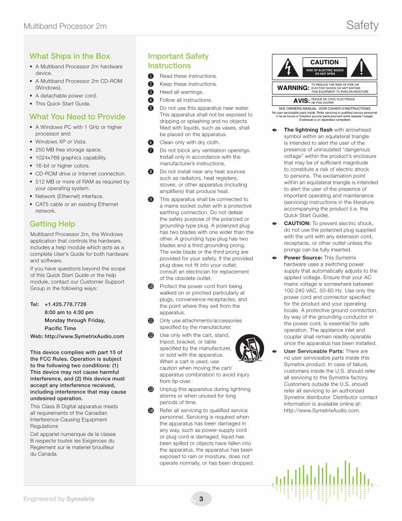
CAUTION
WARNING:TO REDUCE THE RISK OF FIRE ORELECTRIC SHOCK DO NOT EXPOSETHIS EQUIPMENT TO RAIN OR MOISTURE
DO NOT OPENRISK OF ELECTRIC SHOCK
Important Safety Instructions! Read these instructions.
@ Keep these instructions.
# Heed all warnings.
$ Follow all instructions.
% Do not use this apparatus near water. This apparatus shall not be exposed to dripping or splashing and no objects filled with liquids, such as vases, shall be placed on the apparatus.
^ Clean only with dry cloth.
& Do not block any ventilation openings. Install only in accordance with the manufacturer’s instructions.
* Do not install near any heat sources such as radiators, heat registers, stoves, or other apparatus (including amplifiers) that produce heat.
( This apparatus shall be connected to a mains socket outlet with a protective earthing connection. Do not defeat the safety purpose of the polarized or grounding-type plug. A polarized plug has two blades with one wider than the other. A grounding type plug has two blades and a third grounding prong. The wide blade or the third prong are provided for your safety. If the provided plug does not fit into your outlet, consult an electrician for replacement of the obsolete outlet.
BL Protect the power cord from being walked on or pinched particularly at plugs, convenience receptacles, and the point where they exit from the apparatus.
BM Only use attachments/accessories specified by the manufacturer.
BN Use only with the cart, stand, tripod, bracket, or table specified by the manufacturer, or sold with the apparatus. When a cart is used, use caution when moving the cart/apparatus combination to avoid injury from tip-over.
BO Unplug this apparatus during lightning storms or when unused for long periods of time.
BP Refer all servicing to qualified service personnel. Servicing is required when the apparatus has been damaged in any way, such as power-supply cord or plug cord is damaged, liquid has been spilled or objects have fallen into the apparatus, the apparatus has been exposed to rain or moisture, does not operate normally, or has been dropped.
Safety
What Ships in the Box• AMultibandProcessor2mhardware
device.
• AMultibandProcessor2mCD-ROM(Windows).
• Adetachablepowercord.
• ThisQuickStartGuide.
What You Need to Provide• AWindowsPCwith1GHzorhigher
processor and:
• WindowsXPorVista.
• 250MBfreestoragespace.
• 1024x768graphicscapability.
• 16-bitorhighercolors.
• CD-ROMdriveorInternetconnection.
• 512MBormoreofRAMasrequiredbyyour operating system.
• Network(Ethernet)interface.
• CAT5cableoranexistingEthernetnetwork.
Getting HelpMultiband Processor 2m, the Windows application that controls the hardware, includes a help module which acts as a complete User’s Guide for both hardware and software.
If you have questions beyond the scope of this Quick Start Guide or the help module, contact our Customer Support Group in the following ways:
Tel: +1.425.778.7728
8:00 am to 4:30 pm
Monday through Friday,
Pacific Time
Web: http://www.SymetrixAudio.com
This device complies with part 15 of the FCC Rules. Operation is subject to the following two conditions: (1) This device may not cause harmful interference, and (2) this device must accept any interference received, including interference that may cause undesired operation.
ThisClassBDigitalapparatusmeetsall requirements of the Canadian Interference-Causing Equipment Regulations
Cet appariel numerique de la classe BrespectetouteslesExigencesduReglement sur le materiel brouilleur du Canada.

6408 216th Street SW | Mountlake Terrace, WA 98043 USA
T +1.425.778.7728 F +1.425.778.7727 | www.SymetrixAudio.com 4
Quick Start GuideRemote Warning
The RJ45 connectors labeled “REMOTE” are only for use with AirTools Multiband Processor 2m remotes.
DO NOT plug the REMOTE connectors on this product into any RJ45 connector labeled “ETHERNET”, “SYMLINK” or “COBRANET”. The “REMOTE”
RJ45 connectors on this product contain 24 VDC which can damage Ethernet, SymLink, CobraNet or
other circuitry utilizing an RJ45 connector.

5
Multiband Processor 2m Introduction
IntroductionThe AirTools Multiband Processor 2m has been created to provide comprehensive broadcast audio level and quality optimization. The deployment of multiple floating point DSP modules (see Features reverse side) results in listener perceived improvements in tone, intelligibility and intensity regardless of the type of audio program or its source.
Our hardware component selection and design methodologies have produced a minimum latency digital processor with wide dynamic range and extremely low distortion (see Performance Data reverse side).
The 2m is set up from a wizard driven Windows application. Presets are recalled manually from the front panel, network computer or optional controller hardware. Automatic recall by time of day is done using the onboard event scheduler.
There’s a lot more to learn about the 2m. Visit our website at www.SymetrixAudio.com for a free, unregistered download of the 2m Windows application and Quick Start Guide.
AirTools products are Engineered by Symetrix to help you Control Your Airspace.
ApplicationsAudio level and sound quality optimization for:
• AM/FM/TVprogramaudio• Satelliteuplink• Satelliteingest• Headphoneairchainsimulation• Internetstreaming• Alternatelanguageprogramming• Instudioliveperformance“mastering”• Microwavelinks• Telco/VoIPfeeds/returns
Features• Two(2)analoglineinputs,one(1)AES3input,two(2)line
outputs,one(1)AES3output,wordclockinputplususerconfigurable audio input failover and stereo/mono/MS encode/MS decode operating modes.
• Processingmodulesincludeprogrammablefilters,phaserotator, de-esser, downward expander, broadband automaticgaincontrol(AGC),8-bandparametricequalizer,4-way programmable crossover, 4-band multiband compressor and limiter, stereo image enhancer, acoustic environment simulator, clipper, and alignment delay.
• Configurenamedpresetstoaccommodateanyformat– up to 50, including factory presets – configured via the included Windows® software.
• Presetsarerecalledmanuallyfromthefrontpanel,networkcomputer or optional controller hardware. Automatic recall by time of day is done using the onboard event scheduler.

6408 216th Street SW | Mountlake Terrace, WA 98043 USA
T +1.425.778.7728 F +1.425.778.7727 | www.SymetrixAudio.com 6
Quick Start GuideMechanical and Performance Data
Mechanical DataITEM DESCRIPTION DETAILS
Space Required 1U(WDH:48.02cmx23.11cmx4.37cm/18.91inx9.1inx1.72in),depthisspecifiedfromfrontpaneltoback of connectors.
Allowatleast3inchesadditionalclearanceforrearpanelcon-nections. Additional depth may be required depending upon your specific wiring and connections.
Electrical 100-240 VAC, 50/60 Hz, 25 Watts maximum. Nolinevoltageswitchingrequired.
VentilationMaximum recommended ambient operating temperature is30C/86F.
Ensure that the left and right equipment sides are unobstructed (5.08cm,2inminimumclearance).Theventilationshouldnotbeimpeded by covering the ventilation openings with items such as newspapers, tablecloths, curtains, etc.
Shipping Weight 12 lbs. (5.44 kg)
Performance DataITEM DESCRIPTION DETAILS
ANALOG INPUTS
Nominal Input Level Analog:+4dBuor-10dBVlinelevel(software selectable)with20dBofheadroom
Digital:-20dBFS
NOTE: For unbalanced analog input, either reference the minus input terminal to the signal source ground (preferred) or ground the minus input to the adjacent ground terminal (tie low to ground). Using the second method deprives you of the common mode rejection inherent in a balanced input, even when coming from an unbalanced source.
Maximum Input Level Analog:+23dBu
Digital:0dBFS
Input Impedance Analog:6.67Ωbalanced,3.3Ωunbalanced
Digital:110Ω
CMRR >55dB@1kHz,unitygain
A/D Conversion 24-bit delta/sigma
A/D Dynamic Range 116dB(A-Weighted)
A/D THD+Noise -102dB(un-weighted);1kHz@-2dBFSwith0dBgain
A/D Latency 0.25 mS
ANALOG OUTPUTS
Nominal Output Level Analog:+4dBulinelevelwith20dBofheadroom
Digital:-20dBFS
NOTE: For unbalanced analog output, float (do not connect) the minusoutputterminal.Unbalancedusageresultsin6dBloweroutput level.
Maximum Output Level Analog:+24dBu
Digital:0dBFS
Output Impedance Analog:200Ωbalanced,100Ωunbalanced
Digital:110Ω
D/A Conversion 24-bit delta/sigma
D/A Dynamic Range 114dB(A-Weighted)
D/A THD+N -98dB(un-weighted);1kHz@-2dBFS
D/A Latency 0.2 mS
SYSTEM
Nominal Sampling Rate 48kHz
Output Sample Rate 44.1or48kHzinternal,orequaltoAES/Wordinput
Sync Input Range (Word or AES) 22-192KHz
A/D/A Frequency Response 20Hz-20kHz,+/-0.25dB
A/D/A Dynamic Range 113dB(A-Weighted)
D/D Dynamic Range >140dB
A/D/A Latency <0.7mS;withallDSPactive
D/D Latency <1.0mS;withallDSPactive

7
Multiband Processor 2m Front and Rear Panel
Front PanelITEM DESCRIPTION DETAILS
MENU / UP / DOWN Momentary push buttons Preset Recall
1. Press MENU while on the home screen to select a preset recall. Use the UP and DOWN buttons to choose the desired preset recall.
2. Press the MENU button to recall the selected preset.
3.PressMENU again to confirm recall, or use the UP/DOWNbuttonstochoose“No”thenpress MENU to cancel the recall.
System Information
• PressandHoldMENU to enter or exit the System Information Menus.
Input / Output Meters Eight(8)segmentLEDladderme-ters, one meter of eight segments for each input and output
Illuminatesgreenuptoandincluding0dBu,amberbetween>0andupto+23dBu,andredtoindicateclipping(>+23dBu)oneachinputandoutput.
Power GreenLED Illuminatestoindicatethedeviceispoweredon.Note:ThepowerLEDwillflashwhilethedevice is booting.
Network Bi-colorLED Illuminates green to indicate network (Ethernet) activity, amber to indicate acquisition of a network address in DHCP mode.
REMOTE (LED) GreenLED Illuminates to indicate REMOTE port connection (front or rear REMOTE port).
REMOTE (Connector) RJ45 connector Distributes power and control data to a 2m Remote Control. Uses standard straight-through UTP CAT5 cabling.
1! Warning! Refer to the Remote Warning for compatibility information.
Rear PanelITEM DESCRIPTION DETAILS
Power Input IEC3prongjack Accepts power from detachable IEC power cable (100-240 VAC, 50-60 Hz, 25 Watts max). Connect only to a grounded power outlet.
Remote RJ45 connector Distributes power and control data to a 2m Remote Control. Uses standard straight-through UTP CAT5 cabling. 1! Warning! Refer to the Remote Warning for compatibility information.
RS-485 One(1)3-pinEuroblockconnector Reserved for factory use only.
Ethernet RJ45 connector Communicationsinterfaceforthe2mapplicationrunningonthehostPCaswellas3rdpartycontrol automation or scheduling systems. Uses standard straight-through UTP CAT5 cabling. Features auto-crossover sensing for direct device-to-device connections.
AES3 Output Two(2)MaleXLRconnector Sampleratesoftwareselectablebetween44.1or48kHz,orrateofAES/WordClockInput.
AES3 Input One(1)FemaleXLRconnector Acceptssampleratesfrom22-192kHz,samplerateconvertsto48kHz.Maybesyncsourcefor AES Output.
Lock GreenLED Lightssolidtoindicateavalidwordclockconnectionbetween22and192kHz.
Term GreenLED Lightssolidtoindicatesoftware-selectablewordclockinputtermination.
Word Clock Input FemaleBNCconnector AcceptsTTLorCMOS-levelwordclocksignalsfrom22to192kHz.
Analog Outputs Two(2)MaleXLRconnectors Two (2) balanced analog line level audio outputs, individually software-selectable levels of -10 dBVor+4dBu.
Analog Inputs Two(2)FemaleXLRconnectors Two(2)balancedanalogaudioinputswithindividuallysoftware-selectablelevelof-10dBVor+4dBu.

6408 216th Street SW | Mountlake Terrace, WA 98043 USA
T +1.425.778.7728 F +1.425.778.7727 | www.SymetrixAudio.com 8
Quick Start GuideHardware Connections
POWERConnect the IEC connector end of the supplied AC cord to the receptacle on the rear of the 2m. Connect the AC connector end of the supplied AC cord to an AC power source that is of the correct voltage and frequency (100-240 VAC, 50-60 Hz). Use only the power cord and connector specified for the product and your operating locale.
When the 2m is powered up correctly, the POWER LED on the front of the unit will be lit solid green.
REMOTEUsing a standard straight-through CAT5 cable terminated with RJ45 connectors, connect your 2m remote control to either the front panel or rear panel REMOTE port according to the guidelines in your remote’s documentation.
When a remote is connected to the 2m, the REMOTE LED on the front of the unit will be lit solid green.
CAUTION: DO NOT plug the REMOTE connectors on this product into any RJ45 connector labeled “ETHERNET”, “COBRALINK” or “SYMLINK”. Refer to the Remote Warning for compatibility information.
RS-485Reserved for factory use only.
EthernetUsing a standard straight-through CAT5 cable terminated with RJ45 connectors, connect the2m’sETHERNETporttoeitheryourcomputer’sEthernetportortoanexistingEthernetnetwork.YoumaywishtoreviewtheNetworkConfigurationsectionformoreinformation.
Whenthe2mhasaphysicalnetworkconnection,theamber“link”LEDontheETHERNET connector will be lit solid.
Whenthereisnetworkcommunication,thegreen“activity”LEDontheETHERNET connector and the NETWORK LED on the front of the unit will flash accordingly.
NOTE: The 2m’s Ethernet port will automatically sense a device-to-device connection so that a standard straight-through Ethernet cable may always be used. A cross-over cable is not required.
WORD CLOCK INPUTIfavailableanddesired,connectahouseWordClockfeedhereusing75ΩRG59orbettercoaxialcableterminatedwithBNCconnectors.
Remember to set the Sync Source to Word in the System area of the application.

9
Multiband Processor 2m Hardware Connections
AES3 OUTPUTConnect the AES OUTjacktoyourdownstreamequipment’sAESINjackusingastandard110ΩAEScableterminatedwiththeappropriateXLRconnectors.
AES3 INPUTConnect the AES IN jack to your upstream equipment’s AES OUT jack using a standard 110ΩAEScableterminatedwiththeappropriateXLRconnectors.
TheAESinputcanacceptasamplefrequencyrangeof22-192kHzandwillsamplerateconvertthesignaltothesystemnominalrateof48kHz.ThisinputmayalsobeusedasthesampleratesourcefortheAESoutput rate.
ANALOG OUTPUTSUsingstandardmic/linecablesterminatedononeendwithfemaleXLRconnectorsandappropriate connectors for your line destination devices on the other end, connect the femaleXLRendsintotheANALOG OUTPUTS of the 2m and the opposite ends into yourdestinationdevice’sinputs.Theseoutputsare+4dBubalancedlineleveloutputsby default. If you need an unbalanced output, see the analog audio wiring diagrams in the Audio Wiring Reference.
NOTE: Wiring the outputs to an unbalanced cable will typically result in an output level thatis6dBlowerthantheoutputlevelachievedusingabalancedcable.Ifwiringtoanunbalanceddestination,youmayneedtochangethe2m’soutputlevel.RefertotheAnalogLevelsettingwithintheOutputmodule of the 2m software.
ANALOG INPUTSUsingstandardmic/linecablesterminatedononeendwithmaleXLRconnectorsandappropriateconnectorsforyourlinesourcesontheotherend,connectthemaleXLRends into the ANALOG INPUTS of the 2m and the opposite ends into your source devices’ outputs. Refer to the Audio Wiring Reference for more information.
NOTE: Wiring the inputs to an unbalanced cable will typically result in an input level thatis6dBlowerthantheinputlevelachievedusingabalancedcable.Ifwiringtoanunbalanced source, you may need to adjust the 2m’s input level – refer to the Input module of the 2m software.
INPUTS TIP:The 2m features an input “failover” mode so that both analog and AES inputs may be hooked up simultaneously. In the event that the designated input source drops below a user-determined threshold for a user-determined period of time, the 2m will automatically switch to the other input source. Refer to the 2m software to setup the input failover parameters.

6408 216th Street SW | Mountlake Terrace, WA 98043 USA
T +1.425.778.7728 F +1.425.778.7727 | www.SymetrixAudio.com 10
Quick Start GuideSignal Flow
HO
ST PRO
CESSO
R
EthernetW
ord Clock
Rem
ote
(Rear Panel)
Left Channel
Right C
hannel
Rem
ote
(Front Panel)
DSP PR
OC
ESSOR
Left ChannelA
nalog In
Right C
hannel
Left Channel
Mute
Right ChannelA
nalog InM
ute
L-Channel
DSP Bypass
Inv.
R-C
hannelD
SP Bypass
Left ChannelO
utput Level
Right Channel O
utput Level
Left ChannelA
nalog Out
AES
Output
R-C
h.
L-Ch.
AES
Analog
AES
Analog
Inv.
AES In
Failover
Failover
Input Mode
Stereo
Encode
Decode
Mono
MS
MS
Digi
Trim
Digi
Trim
Master
Stereo Output
Balance
Output M
ode
Stereo
Encode
Decode
Mono
MS
MS
R-Delay
L-Delay
Right ChannelA
nalog Out
+4
-10
Analog Level
+4
-10
Analog Level
-10 dBV
+4 dBu
Gain Set
-10 dBV
+4 dBu
Gain Set
Pre-Crossover D
SP
StereoH
PF/LPFBypass
Active
Bypass
Active
StereoD
eEsser/Expander
Bypass
Active
Bypass
Active
StereoA
GC
Bypass
Active
Bypass
Active
StereoEqualizer
Bypass
Active
Bypass
Active
Post-Crossover D
SP
Bypass
Active
Bypass
Active
StereoEnhancer
Bypass
Active
Bypass
Active
StereoClipper
Bypass
Active
Bypass
Active
Noise/Tone
Generator
LRBalance
Bypass
Active
LR
LR
Bypass
Active
4-Way C
rossover / DSP / M
ixer
Right
Channel
LeftC
hannel
Bypass
Active
High Band
Compressor
Bypass
Active
High BandLim
iter
Bypass
Active
Mid-H
ighBand
Compressor
Bypass
Active
Mid-H
ighBand
Limiter
Bypass
Active
Low-M
id Band
Compressor
Bypass
Active
Low-M
idBand
Limiter
Bypass
Active
Low Band
Compressor
Bypass
Active
Low Band
Limiter
Mixer
High Band
Mid-H
ighBand
Low-M
idBand
Low Band
Left
Right
High Band
Mid-H
ighBand
Low-M
idBand
Low Band
Left
Right 4-W
ayCrossover
Bypass
Active
Bypass
Active
11
Multiband Processor 2m Wiring Reference
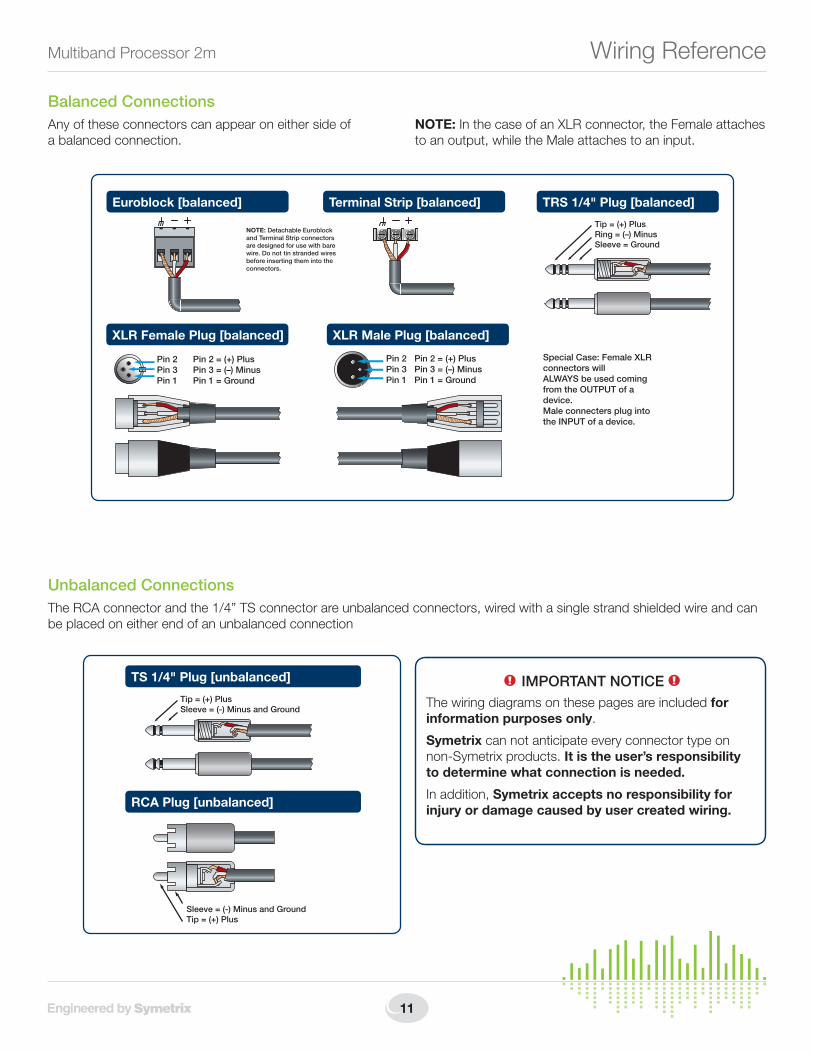
XLR Male Plug [balanced]
Pin 2Pin 3Pin 1
Pin 2 = (+) PlusPin 3 = (–) MinusPin 1 = Ground
XLR Female Plug [balanced]
Pin 2 = (+) PlusPin 3 = (–) MinusPin 1 = Ground
Pin 2Pin 3Pin 1
Terminal Strip [balanced] TRS 1/4" Plug [balanced]
Tip = (+) PlusRing = (–) MinusSleeve = Ground
Euroblock [balanced]
NOTE: Detachable Euroblock and Terminal Strip connectors are designed for use with bare wire. Do not tin stranded wires before inserting them into the connectors.
Special Case: Female XLR connectors willALWAYS be used coming from the OUTPUT of a device.Male connecters plug into the INPUT of a device.
Balanced ConnectionsAny of these connectors can appear on either side of a balanced connection.
NOTE:InthecaseofanXLRconnector,theFemaleattachesto an output, while the Male attaches to an input.
Unbalanced ConnectionsThe RCA connector and the 1/4” TS connector are unbalanced connectors, wired with a single strand shielded wire and can be placed on either end of an unbalanced connection
TS 1/4" Plug [unbalanced]
Tip = (+) PlusSleeve = (-) Minus and Ground
RCA Plug [unbalanced]
Sleeve = (-) Minus and GroundTip = (+) Plus
1! IMPORTANT NOTICE 1!
The wiring diagrams on these pages are included for information purposes only.
Symetrix can not anticipate every connector type on non-Symetrix products. It is the user’s responsibility to determine what connection is needed.
In addition, Symetrix accepts no responsibility for injury or damage caused by user created wiring.

6408 216th Street SW | Mountlake Terrace, WA 98043 USA
T +1.425.778.7728 F +1.425.778.7727 | www.SymetrixAudio.com 12
Quick Start GuideWiring Reference
Unbalanced Connections:Unbalanced out to balanced inThe RCA connector and the 1/4” TS connector are unbalanced connectors. However, the wiring differs depending on if they are sending to, or receiving from a balanced connector.
In this example, the unbalanced connector is sending signal to a balanced connector. When wiring this connection, use a shielded twisted pair cable. The balanced side wires the same as a standard, balanced connection. On the unbalanced side, you wire the white (minus) wire together with the ground. This provides some common mode rejection at the balanced input.
Unbalanced Connections:Balanced out to unbalanced inWhen your output requires a balanced connector, but you
are sending signal to an unbalanced input, the rules change. Use a single strand shielded wire. Wire only to the plus and ground terminals of what would the typically be the balanced connector.
XLR Male Plug [balanced]
TS 1/4" Plug [unbalanced out to balanced in]
TRS 1/4" Plug [balanced]
Euroblock [balanced]
Tip = (+) PlusSleeve = (-) Minus and Ground
RCA Plug [unbalanced out to balanced in]
Sleeve = (-) Minus and GroundTip = (+) Plus
Terminal Strip [balanced]
TS 1/4" Plug [balanced out to unbalanced in]
Tip = (+) PlusSleeve = Ground
RCA Plug [balanced out to unbalanced in]
Sleeve = GroundTip = (+) Plus
Euroblock [unbalanced] Terminal Strip [unbalanced]
XLR Female Plug [unbalanced]
Pin 2 = (+) PlusPin 3 = UnusedPin 1 = Ground
Pin 2Pin 3Pin 1
TRS 1/4" Plug [balanced]Tip = (+) PlusRing = UnusedSleeve = Ground

13
Multiband Processor 2m 2mNetworking
Network Configuration
The 2m is setup and controlled by a host computer via Ethernet. This requires the host computer to be connected to the 2m directly via a standard CAT5 Ethernet cable, indirectly via an Ethernet switch, or via an existing Ethernet network.
The primary difference between the three methods of connection is that in the first two, the 2m software application assumes there is no DHCP server or other network infrastructure in place. It assumes the 2m is using a self-generated IP address and adjusts its connection steps appropriately. In the third method, it is assumed that a DHCP server and/or router with DHCP server are already present on the existing network so the 2m may already have obtained an IP address. Consult your network administrator if in doubt.
General Notes1. The 2m boots up with DHCP enabled by default. This
means that as soon as you connect it to a network, it will look for a DHCP server in order to obtain an IP address. If a DHCP server is present, the 2m will get its IP address from it. This process may take several minutes. With your PC attached to the same network and thus getting its IP address from the same DHCP server, all will be ready to go.
2. If your network does not have a DHCP server, the 2m will not be able to obtain an IP address. While waiting, the 2m will default to a private IP address in the range of169.254.x.xwherex.xisthelastfouralphanumericcharacters of the 2m’s MAC address (MAC address hex value is converted to decimal for IP address). The 2m’s MAC address can be found on a sticker on the bottom of the 2m or within the front panel System menu. When there is no DHCP server present to assign IP addresses to either the 2m or your PC, you may need to configure yourPCwithastaticIPintherangeof169.254.x.xwitha Subnet Mask of 255.255.0.0 in order to communicate
with the 2m in a direct connect mode. However, if your PC is using the default network settings, it should also have automatically self-assigned a similar private IP addressintherangeof169.254.x.x,andifthisisthecase, you should be able to connect to the 2m directly. Even if the PC’s default settings have been changed, the 2m will try to establish communications by setting up appropriate routing table entries to reach devices with 169.254.x.xaddresses.
3. Inthecaseofthefirsttwomethods(directconnectionand indirect connection), the 2m software will attempt to set-up appropriate routing table entries for a seamless connection regardless of the IP addresses of your PC and 2m. However, under Windows® Vista, administrative privileges are required to allow the 2m software to modify the routing table. For best results, launch the 2m software while logged in as an administrator, or choose to run the software as an administrator. Note: To run a program as the Administrator under Vista, right click on the program’s icon or shortcut and choose “Run as administrator”.
4. The 2m will display its current IP address, subnet mask, and gateway as well as other useful information on the front panel display when in System Mode. To enter System Mode, hold down the Menu button for 5 seconds. Then the up and down arrow keys can be used to move between various displays. This information may be useful for troubleshooting.
Network configuration of the 2m:Connecting to the 2m from a host computer on the same LANBoththe2mandthehostcomputerrequirethefollowing 3items:
1. IP Address - The unique address of a node on a network.
2. Subnet Mask - Configuration that defines which IP Addresses are included in a particular subnet.
3.DefaultGateway(optional)-TheIPaddressofadevicethat routes traffic from one subnet to another. (This is only needed when the PC and 2m are on different subnets).
If you are putting the 2m on an existing network, a network administrator will be able to provide the above information or it may have been provided automatically by a DHCP server. For security reasons, it is not recommended to put the 2m directly on the Internet. If you do, a network administrator or your Internet Service Provider can provide the above information.
6408 216th Street SW | Mountlake Terrace, WA 98043 USA
T +1.425.778.7728 F +1.425.778.7727 | www.SymetrixAudio.com 14
Quick Start Guide2mNetworking
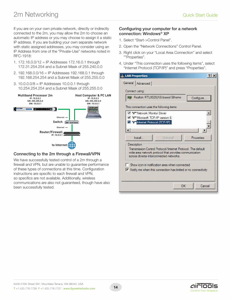
If you are on your own private network, directly or indirectly connected to the 2m, you may allow the 2m to choose an automatic IP address or you may choose to assign it a static IP address. If you are building your own separate network with static assigned addresses, you may consider using an IP Address from one of the ”Private-Use” networks noted in RFC-1918:
1.172.16.0.0/12=IPAddresses172.16.0.1through172.31.254.254andaSubnetMaskof255.240.0.0
2.192.168.0.0/16=IPAddresses192.168.0.1through192.168.254.254andaSubnetMaskof255.255.0.0
3.10.0.0.0/8=IPAddresses10.0.0.1through10.254.254.254 and a Subnet Mask of 255.255.0.0
Connecting to the 2m through a Firewall/VPNWe have successfully tested control of a 2m through a firewallandVPN,butareunabletoguaranteeperformanceof these types of connections at this time. Configuration instructionsarespecifictoeachfirewallandVPN,so specifics are not available. Additionally, wireless communications are also not guaranteed, though have also been successfully tested.
Configuring your computer for a network connection: Windows® XP
1. Select “Start->Control Panel”.
2.Openthe“NetworkConnections”ControlPanel.
3.Rightclickonyour“LocalAreaConnection”andselect””Properties”.
4. Under “This connection uses the following items”, select “Internet Protocol (TCP/IP)” and press “Properties”.
Router/FirewallIP: 10.0.0.1
Switch
Host Computer & PC LANIP: 10.0.0.3
SM: 255.255.0.0GW: 10.0.0.1
Multiband Processor 2mIP: 10.0.0.2
SM: 255.255.0.0GW: 10.0.0.1
Ethernet
Ethernet
to Internet

15
Multiband Processor 2m 2mNetworking
5. On the “General” tab, you may select “Use the following IP address” to enter in the appropriate information if using staticassignedaddresses.(DNSserverisnotrequiredforconnection to a 2m). Otherwise, leave set to “Obtain an IP address automatically” if using DHCP.
6.PressOKtosaveand“Close”toexitoutofthe“LocalArea Connection Properties”.
Configuring your computer for a network connection: Windows® Vista
1. Select “Start->Control Panel”.
2.Select“NetworkandInternet”.
3.Openthe“NetworkandSharingCenter”.
4. Choose “Manage network connections” on the left.
5. Right-click the desired connection and choose “Properties”.
6408 216th Street SW | Mountlake Terrace, WA 98043 USA
T +1.425.778.7728 F +1.425.778.7727 | www.SymetrixAudio.com 16
Quick Start Guide
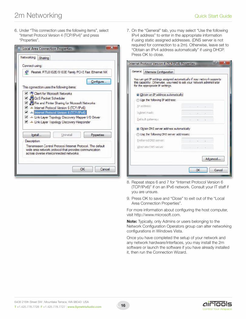
6. Under “This connection uses the following items”, select “Internet Protocol Version 4 (TCP/IPv4)” and press “Properties”.
7.Onthe“General”tab,youmayselect“UsethefollowingIPv4 address” to enter in the appropriate information ifusingstaticassignedaddresses.(DNSserverisnotrequired for connection to a 2m). Otherwise, leave set to “Obtain an IPv4 address automatically” if using DHCP. Press OK to close.
8.Repeatsteps6and7for“InternetProtocolVersion6(TCP/IPv6)” if on an IPv6 network. Consult your IT staff if you are unsure.
9.PressOKtosaveand“Close”toexitoutofthe“LocalArea Connection Properties”.
For more information about configuring the host computer, visit http://www.microsoft.com.
Note: Typically, only Admins or users belonging to the NetworkConfigurationOperatorsgroupcanalternetworkingconfigurations in Windows Vista.
Once you have completed the setup of your network and any network hardware/interfaces, you may install the 2m software or launch the software if you have already installed it, then run the Connection Wizard.
2mNetworking

17
Multiband Processor 2m SoftwareInstallation•ConnectionWizard
Multiband Processor 2m SoftwareInstallationThe Multiband Processor 2m software provides real-time set-up and control from a Win dows PC environment.
Use one of the following procedures to install the Multiband Processor 2m software on your computer.
From the CD-ROM:
1. Insert the CD into your computer’s CD-ROM drive.
2. Open “My Computer”. The “My Computer” icon is typically on your desktop or in the “Start” menu.
3.DoubleclickonyourCD-ROMdrive.Thisistypicallydrive“D:\”. If your CD-ROM drive isn’t “D:\”, then substitute its drive letter.
4. Double-click “Setup.exe”.From the Symetrix web site (http://www.SymetrixAudio.com):
1. Download the Multiband Processor 2m software installer from the Symetrix web site.
2. Double-click on the file you just downloaded and follow the on screen directions to install.
The software always starts up in offline mode. Regardless, you can explore the software, experiment to your heart’s content, and perhaps even get useful work done. You can save any device files that you create to your hard drive and transfer them to hardware later.
After installing the software, browse the rest of the Help File, or move on to the Connection Wizard to get connected to your 2m.
Launch the softwareYou can launch the Multiband Processor 2m software via either the Start Menu or the Desktop icon. Once launched, the Multiband Processor 2m software presents the following options:
YoumaychoosetocreateaNewFileusingthefactorydefault settings.
If you choose to open an Existing File on Computer, a list ofrecentlyusedfilesispresented.ABrowsebuttonisalsoavailable to manually locate the file of your choosing from a local drive or network share.
If you choose to open an Existing File on Device, a list of recently connected-to devices is presented. An “Open Connection Wizard” choice is also available in the event that you are unsure of which device to connect to or your device is not listed among the recently connected to devices.
After installing and launching the software and choosing your operating mode above, you may browse the rest of the Help File, or move on to the Connection Wizard to get connected to your 2m.
Connection WizardOnce you have completed the Hardware Connections and connectedyournetwork(refertoNetworkConfiguration),you may open the 2m Application and run the Connection Wizard.
The Connection Wizard can be run by clicking on its icon in the toolbar...
...or from the Tools menu:

6408 216th Street SW | Mountlake Terrace, WA 98043 USA
T +1.425.778.7728 F +1.425.778.7727 | www.SymetrixAudio.com 18
Quick Start Guide
The Connection Wizard opens with the following screen:
Select the option that best represents your network topologyandthenclicktheNextbutton.(RefertoNetworkConfiguration for further help.)
IntheeventthatyourcomputerhasmultipleNetworkInterfacesCards(NICs),thefollowingscreenwillallowyoutoselectthenetworkyouwishtosearchfor2mdevices.NotethatonlyvalidNICswillbeselectable(thosewithanetworkconnection and valid IP address).
SelecttheNICyouwishtouseandthenclicktheNextbutton.
The following screen displays a list of 2m devices found on your network. At the very least, you can select the device youwishtoconnecttoandclicktheNextbutton.However,there are a few more functions on this screen worth mentioning...
Properties:
The (device) Properties dialog allows you to give a device a unique name to help identify it. It also allows you to switch the unit between dynamic (DHCP) IP addressing and static IP addressing.
Flash Device:
ClickingtheFlashDevicebuttonwillcauseallLEDsonthefront of the device to flash for a short time. This can be helpful to distinguish units which have the same or similar names.
Upgrade Firmware:
The 2m Firmware must be matched with the version of the Room Combine Application you are using. The correct firmware for the Application is always distributed with the Application and installed on your hard drive by the Application’s installer. If there is ever any doubt, follow the instructions in the Upgrade Firmware topic to check your firmware version or to upgrade the firmware.
Connection Wizard
19
Multiband Processor 2m Connection Wizard
Refresh List:
ClickingtheRefreshListbuttonwillre-scanthenetworkfordevices and refresh the list of devices. If at first your device is not located, double-check network connections and that thedevice(s)is/arepoweredon.ThenclicktheRefreshListbutton.
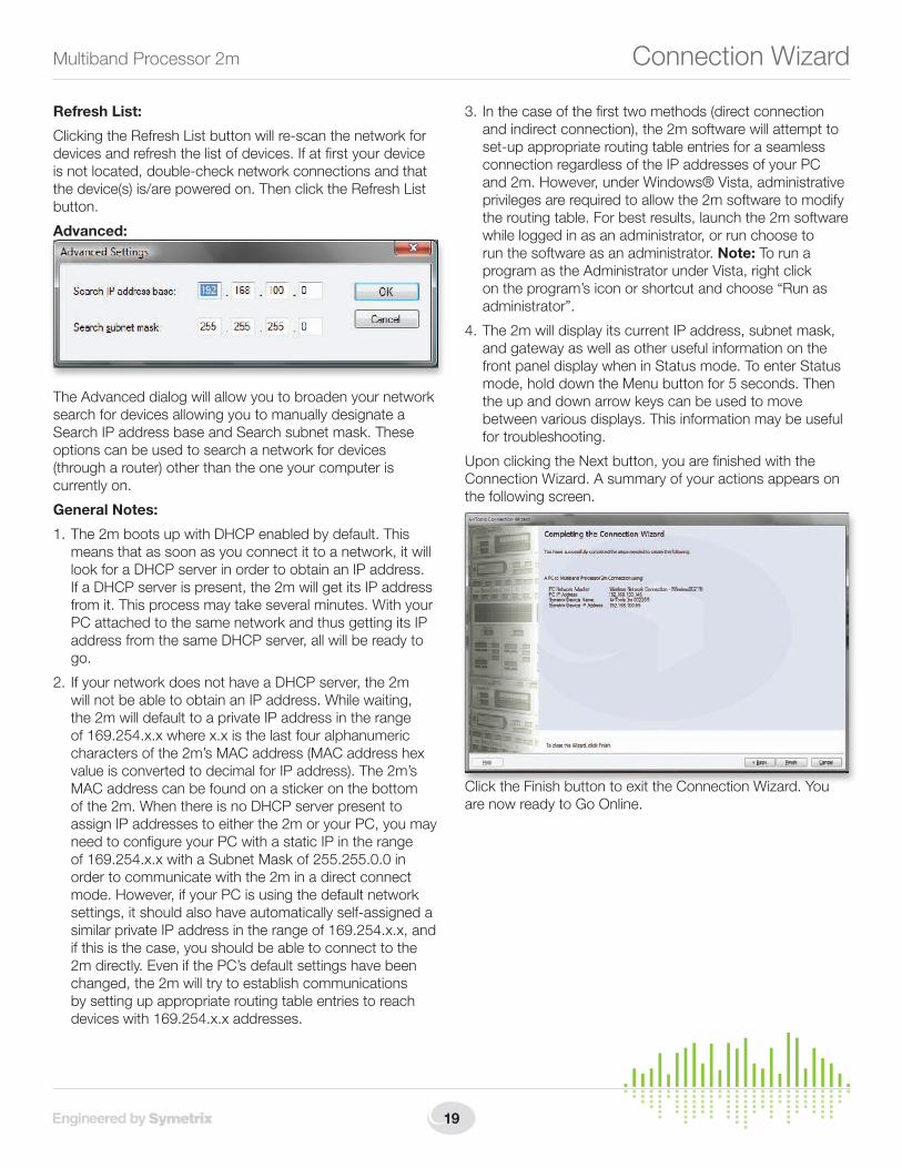
Advanced:
The Advanced dialog will allow you to broaden your network search for devices allowing you to manually designate a Search IP address base and Search subnet mask. These options can be used to search a network for devices (through a router) other than the one your computer is currently on.
General Notes:
1. The 2m boots up with DHCP enabled by default. This means that as soon as you connect it to a network, it will look for a DHCP server in order to obtain an IP address. If a DHCP server is present, the 2m will get its IP address from it. This process may take several minutes. With your PC attached to the same network and thus getting its IP address from the same DHCP server, all will be ready to go.
2. If your network does not have a DHCP server, the 2m will not be able to obtain an IP address. While waiting, the 2m will default to a private IP address in the range of169.254.x.xwherex.xisthelastfouralphanumericcharacters of the 2m’s MAC address (MAC address hex value is converted to decimal for IP address). The 2m’s MAC address can be found on a sticker on the bottom of the 2m. When there is no DHCP server present to assign IP addresses to either the 2m or your PC, you may need to configure your PC with a static IP in the range of169.254.x.xwithaSubnetMaskof255.255.0.0inorder to communicate with the 2m in a direct connect mode. However, if your PC is using the default network settings, it should also have automatically self-assigned a similarprivateIPaddressintherangeof169.254.x.x,andif this is the case, you should be able to connect to the 2m directly. Even if the PC’s default settings have been changed, the 2m will try to establish communications by setting up appropriate routing table entries to reach deviceswith169.254.x.xaddresses.
3. Inthecaseofthefirsttwomethods(directconnectionand indirect connection), the 2m software will attempt to set-up appropriate routing table entries for a seamless connection regardless of the IP addresses of your PC and 2m. However, under Windows® Vista, administrative privileges are required to allow the 2m software to modify the routing table. For best results, launch the 2m software while logged in as an administrator, or run choose to run the software as an administrator. Note: To run a program as the Administrator under Vista, right click on the program’s icon or shortcut and choose “Run as administrator”.
4. The 2m will display its current IP address, subnet mask, and gateway as well as other useful information on the front panel display when in Status mode. To enter Status mode, hold down the Menu button for 5 seconds. Then the up and down arrow keys can be used to move between various displays. This information may be useful for troubleshooting.
UponclickingtheNextbutton,youarefinishedwiththeConnection Wizard. A summary of your actions appears on the following screen.
Click the Finish button to exit the Connection Wizard. You are now ready to Go Online.

6408 216th Street SW | Mountlake Terrace, WA 98043 USA
T +1.425.778.7728 F +1.425.778.7727 | www.SymetrixAudio.com 20
Quick Start GuideGoingOnline•UpgradingFirmware
Going OnlineOnce you have completed the Hardware Connections, connectedyournetwork(refertoNetworkConfiguration),launched the 2m software and run the Connection Wizard, you should be ready to Go Online with your device.
The process of Going Online with a device can go one of two ways: either you are transferring a file currently open on your computer to the device, or you are transferring a file on the device to your computer. Either way, the 2m software must “know” about the device first, which is what the Connection Wizard accomplishes.
After you have successfully run the Connection Wizard and determined the unit you will be going online with, you can click the “Offline” button in the toolbar to toggle it to “Online”. The following dialog will appear offering you the two choices detailed in the previous paragraph:
Make your choice and click OK. You are now online and the “Online/Offline” button in the toolbar will display “Online” as well as the device’s name and IP address with which you are online:
Additionally, the 2m software keeps a list of recently connected devices which you can use to quickly get online with a specific unit - if you already know the name and/or IP address of the unit you wish to connect to and that unit is currently available on the network:
If the specified unit can not be found on the network, you will be prompted to run the Connection Wizard to discover a unit to go online with:
Upgrade Firmware.IMPORTANT: The 2m Firmware must be matched with the version of the Room Combine Application you are using. The correct firmware for the Application is always distributed with the Application and installed on your hard drive by the Application’s installer. If there is every any doubt, follow the instructions below to check your firmware version or to upgrade the firmware.
You must be online with a unit to upgrade the firmware. To upgrade the firmware, launch the Multiband Processor 2m Application and go online to access the Upgrade Firmware dialog found in the Tools pull down menu.
FromtheFirmwareUpdatedialog,clickBrowse...tolocatethe upgrade .cab file.

21
Multiband Processor 2m UpgradingFirmware•A&ESpecs
Select the firmware upgrade .cab file and click Open.
Click the Start button to begin the process and a status bar will show progress of the upgrade.
When finished a confirmation window will appear. Click OK to complete the Firmware Upgrade process.
Architects and Engineers SpecificationsThe device shall provide four inputs (two line level analog andtwoAES3digital)andfouroutputs(twolinelevelanalogandtwoAES3digital).Allsignalprocessing(includinginputgains) shall be controllable via software. Audio inputs and outputsshallbeaccessedviarearpanelXLRconnectors.Aninput failover mode may be enabled to automatically switch the active inputs should a user-determined length of audio loss occur.
The Graphical User Interface (GUI) software shall be installer programmableusingtheWindows®XPorVistaoperatingsystem. Computer connection and control shall be via the device’s rear panel Ethernet connector. The GUI shall provide display and control of all signal processing and configuration functions including, but not limited to: Input and Output Gain, M/S Encoding and Decoding, Highpass Filtering,LowpassFiltering,PhaseRotation,De-essing,Downward Expansion, Automatic Gain Control, Parametric Equalization,MultibandCompression,MultibandLimiting,Stereo Enhancement and Clipping.
The front panel shall include input and output level indication aswellasindicatorsforPOWER,NETWORK,andREMOTE.Additionally,afrontpanelLCDshalldisplaycertainsystemparameters and may be used for preset recall via the front panelUP,DOWNandMENUbuttons.
External control shall include preset selection and/or comprehensive parameter adjustment, depending upon the particular remote in use, and shall be via industry-standard CAT5 cable with RJ45 connectors to the front or rear panel REMOTE ports. All program memory shall be non-volatile andprovideprogramsecurityshouldpowerfail.3rdpartycontrol systems may interface via Ethernet using a published Control Protocol.
Audioconversionshallbe24-bit,48kHzwithconfigurableoutput sample rate. The dynamic range of the processor shallnotbelowerthan113dBA-weighted.
The device shall have an IEC power input socket. The device shallmeetUL/CSAandCEsafetyrequirementsandcomplywith CE and FCC Part 15 emissions limits. The device shall be RoHS compliant. The chassis shall be constructed of cold rolled steel and moulded plastic, and mount into astandard19”1UEIArack.The device shall be an AirTools model Multiband Processor 2m, Engineered by Symetrix.

6408 216th Street SW | Mountlake Terrace, WA 98043 USA
T +1.425.778.7728 F +1.425.778.7727 | www.SymetrixAudio.com 22
Quick Start GuideDeclaration of Conformity
Declaration of ConformityWe, Symetrix Incorporated,6408216thSt.SW,
Mountlake Terrace, Washington, USA, declare under our sole responsibility that the product:
Multiband Processor 2m
to which this declaration relates, is in conformity with the following standards:
UL 60065, cUL 60065, IEC 60065, EN 55103-1, EN 55103-2, FCC Part 15, RoHS
The technical construction file is maintained at:
Symetrix, Inc.
6408216thSt.SW
MountlakeTerrace,WA,98043USA
The authorized representative located within the European Community is:
World Marketing Associates
P.O.Box100
St.Austell,Cornwall,PL266YU,U.K.
Dateofissue:October1,2009
Place of issue: Mountlake Terrace, Washington, USA
Authorized signature:
DaneButcher,President,Symetrix Incorporated.
23
Multiband Processor 2m Warranty and Service
The Symetrix Limited WarrantySymetrix, Inc. expressly warrants that the product will be free from defects in material and workmanship for two (2) years from the date the product is shipped from the factory. Symetrix’s obligations under this warranty will be limited to repairing or replacing, at Symetrix’s option, the part or parts of the product which prove defective in material or workmanship within two (2) years from the date the product is shipped fromthefactory,providedthattheBuyergivesSymetrixpromptnoticeof any defect or failure and satisfactory proof thereof. Products may be returnedbyBuyeronlyafteraReturnAuthorizationnumber(RA)hasbeenobtainedfromSymetrix.Buyerwillprepayallfreightchargestoreturn the product to the Symetrix factory. Symetrix reserves the right to inspect any products which may be the subject of any warranty claim before repair or replacement is carried out. Symetrix may, at its option, require proof of the original date of purchase (dated copy of original retail dealer’s invoice). Final determination of warranty coverage lies solely with Symetrix. Products repaired under warranty will be returned freight prepaid via United Parcel Service by Symetrix, to any location within the Continental United States. Outside the Continental United States, products will be returned freight collect.
The foregoing warranties are in lieu of all other warranties, whether oral, written, express, implied or statutory. Symetrix, Inc. expressly disclaims any IMPLIED warranties, including fitness for a particular purpose or merchantability. Symetrix’s warranty obligation and buyer’s remedies hereunder are SOLELY and exclusively as stated herein.
This Symetrix product is designed and manufactured for use in professional and studio audio systems and is not intended for other usage. With respect to products purchased by consumers for personal, family, or household use, Symetrix expressly disclaims all implied warranties, including but not limited to warranties of merchantability and fitness for a particular purpose.
This limited warranty, with all terms, conditions and disclaimers set forth herein, shall extend to the original purchaser and anyone who purchases the product within the specified warranty period.
Symetrix does not authorize any third party, including any dealer or sales representative, to assume any liability or make any additional warranties or representation regarding this product information on behalf of Symetrix.
This limited warranty gives the buyer certain rights. You may have additional rights provided by applicable law.
Note: Some Symetrix products contain embedded software and may also be accompanied by control software intended to be run on a personal computer. Said software is specifically excluded from this warranty.
Limitation of LiabilityThe total liability of Symetrix on any claim, whether in contract, tort (including negligence) or otherwise arising out of, connected with, or resulting from the manufacture, sale, delivery, resale, repair, replacement or use of any product will not exceed the price allocatable to the product or any part thereof which gives rise to the claim. In no event will Symetrix be liable for any incidental or consequential damages including but not limited to damage for loss of revenue, cost of capital, claims of customers for service interruptions or failure to supply, and costs and expenses incurred in connection with labor, overhead, transportation, installation or removal of products, substitute facilities or supply houses.
Servicing Your Symetrix ProductIf you have determined that your Symetrix product requires repair services and you live outside of the United States please contact your local Symetrix dealer or distributor for instructions on how to obtain service. If you reside in the U.S. then proceed as follows:
Return AuthorizationAt the Symetrix factory, Symetrix will perform in-warranty or out-of-warranty service on any product it has manufactured for a period of three(3)yearsfromdateofdiscontinuedmanufacture.
BeforesendinganythingtoSymetrix,pleasecontactourCustomerService Department for a Return Authorization (RA) number. The telephonenumberis+1.425.778.7728.Additionally,supportisavailablevia the web site: http://support.SymetrixAudio.com.
In-warranty RepairsTo get your Symetrix product repaired under the terms of the warranty:
1. Call us for an RA number (have the serial number, shipping and contact information and description of the problem ready).
2. Pack the unit in its original packaging materials.
3. Includeyourname,address,daytimetelephonenumber,andabriefstatement of the problem.
4. Write the RA number on the outside of the box.
5. Ship the unit to Symetrix, freight prepaid. We do not accept freight collect shipments.
Just do these five things, and repairs made in-warranty will cost you only one way freight charges. We’ll pay the return freight.
If you don’t have the factory packaging materials, we recommend using an oversize box. Wrap the unit in a plastic bag, surround it with bubble-wrap,andplaceitintheboxsurroundedbyStyrofoampeanuts.Besurethere is enough clearance in the box to protect the rack ears. We won’t return the unit in anything but Symetrix packaging for which we will have to charge you. If the problem is due to operator misuse or error, you will have to pay for both parts and labor. In any event, if there are charges for the repair, you will pay for the return freight. All charges will be COD unless you have made other arrangements (prepaid, Visa or Mastercard).
Out-of-warranty RepairsIf the warranty period has passed, you’ll be billed for all necessary parts, labor, packaging materials, and freight charges. Please remember, you must call for an RA number before sending the unit to Symetrix.

6408 216th Street SW | Mountlake Terrace, WA 98043 USA
T +1.425.778.7728 F +1.425.778.7727 | www.SymetrixAudio.com
ItemNo.53-0046-A
Multiband Processor 2m Quick Start Guide
©2009Symetrix,Inc.Allrightsreserved.PrintedintheUnitedStatesofAmerica.Theinformationinthisdocumentissubjecttochangewithoutnotice.Symetrix,Inc.shallnotbeliablefortechnicaloreditorialerrorsoromissionscontainedherein;norisitliableforincidentalorconsequentialdamagesresulting from the furnishing, performance, or use of this material. Mention of third-party products is for informational purposes only and constitutes neither an endorsement nor a recommendation. Symetrix assumes no responsibility with regard to the performance or use of these products. Under copyright laws, no part of this brochure may be reproduced or transmitted in any form or by any means, electronic or mechanical, without permission in writing from Symetrix, Inc. If, however, your only means of access is electronic, permission to print one copy is hereby granted. The following are eitherTrademarksorRegisteredTrademarksofSymetrix,Inc.:Symetrix,SymNet,SymNetDesigner,SymLinkandCobraLink.WindowsisaRegisteredTrademark of Microsoft, Inc. Other product names mentioned herein may be trademarks and/or registered trademarks of other companies and are property of their respective owners.