nazar 45) date of patent: oct. 21, 1997 · the stripping duty of the deethanizer column and the...
TRANSCRIPT

USOO5678424A
United States Patent (19) 11 Patent Number: 5,678,424 Nazar 45) Date of Patent: Oct. 21, 1997
54 RECTIFED REFLUX DEETHANZER 5,035,732 7/1991 McCue, Jr. . 5,235,479 8/1993 DiCintio et al. .
75 Inventor: Behzad Nazar. Los Angeles, Calif. OTHER PUBLICATIONS
73) Assignee: Brown & Root, Inc., Alhambra, Calif. “Ethylene from NGL Feedstocks-Part 3", K. Ng et al. Hydrocarbon Processing, Dec. 1983, pp. 99-103.
(21) Appl. No.: 589,167 "Ethylene From NGL Feedstocks-Part 4", H. Kister et al 1a- Hydrocarbon Processing. Jan. 1984.
22 Filed: Jan. 22, 1996 "Temperature-Heat Diagrams For Complex cols. 2. Under wood's Method For Side Strippers and Enrichers”, N.A.
Related U.S. Application Data Carlberg, Ind. Eng. Res, vol. 28, pp. 1379-1386, 1989. 60 Provisional application No. 60/005,825, Oct. 24, 1995, Primary Examiner-Ronald C. Capossela (51) Int. Cl. F2s 100 Attorney Agent, or Firm-Lyon & Lyon LLP 52 U.S. Cl. ...................... 62/630; 62/935 57 ABSTRACT 58) Field of Search ....................................... 62/630,935
The present invention is an improvement in the combined 56 References Cited fractionation steps of deethanization and C2 splitting for
ethylene and ethane separation. Theoretical stages are added U.S. PATENT DOCUMENTS to the rectification section of a deethanizer above a liquid or
1,735,558 11/1929 Youker. vapor sidedraw. Polymer grade ethylene product up com 1954,839 4/1934 Youker . prising to 30 percent of the ethylene in the deethanizer feed 1957,818 5/1934 Carney. is obtained in an overhead stream according to the present 2,327,134 8/1943 Schuftan ................................... 62/935 invention. Lesser recovery at the same ethylene purity or 2,327,643 8/1943 Houghland. higher recovery at lower ethylene purity are obtained vary
St al. ...................... '' ing recovery or numbers of additional stages in the rectifi y e s -
4,430,102 2/1984 Tedder ...................................... cation. An overall reduction in total cold utilities for the overhead condensers for the deethanizer and downstream C2 4,436,540 3/1984 Dowd et al. . o 4,720,293 1/1988 Rowles et al. . splitter are obtained in practicing the present invention. 4,726,826 2/1988 Crawford et al. . 4,900,347 2/1990 McCue, Jr. et al. . 12 Claims, 5 Drawing Sheets
S2OO S20 E20g E2C1 2) CA EthOne
M (S Recycle (S E2O7 210
E208
S /
211 w \
200 n N 209 Ethylene
E2OC E205 Product
O E204 (2)
To C3 CY Splitter 204

5,678,424 Sheet 1 of 5 Oct. 21, 1997 U.S. Patent

5,678,424 U.S. Patent
U.S. Patent Oct. 21, 1997 Sheet 3 of 5 5,678,424
d C
2. DNP. G 5 LU -
SS NQ SS
O) OO OD O. O.) 3.
n r
O) CN
(f) DN O a H
CN &
N O 2
S ?)
O
N
O O O O O O O CO L?) r- N CN vm
JeZu DuleeO uOJJ pej9A009.) eue Kun 24

U.S. Patent Oct. 21, 1997 Sheet 5 of 5 5,678,424
Azz.6 COLUMN COMPOSITION PROFILE - WAPOR CUS
1.0 +111111111111111111111111111111111 ----- ----------- ----2222222+ 11 222
1 2 O.9 it 1. 2 --
1
2 0.8 - --------- ----------- ----------- ------------ -1 --- - - - a -a - - - - --
V h
A 0.7 + -- P dP
O 12 R 0.6 - --------- ---------------------- ------------ ----------- ------------
C O 0.5 - k -- M
g 0.4 + --------- + -------- - - --------- ------------ ----------- ------------
2 : 0.5 + -- O P
N 2 0.2 + --------- ----------- ----------- ------------ 2-- ------------
0.1 2 I + o u --
2 1
22' 0.0 2222222222222222222222222222222222+--------------- --- 11111111+
10 2O 30 40 50 6. Condenser TRAY NUMBER Reboiler
KEY. 1 - C2's 2 - C3's--

5,678.424 1
RECTED REFLUX DEETHANZER
This is a continuation-in-part of provisional patent appli cation Ser. No. 60/005,825 filed Oct. 24, 1995.
The present invention relates to the fractionation of light hydrocarbons. The present invention especially relates to deethanization.
BACKGROUND
The present invention relates to deethanization and ethylene/ethane splitting fractionation steps of cracked gases for olefin recovery. In order to properly appreciate the technological field of the fractionation trains used for sepa ration of olefins from other components in cracked gas, the article "Ethylene from NGL feedstocks-Part 3 Flow Scheme Comparison" (K. Nget al. Hydrocarbon Processing, Dec. 1983, pp. 99-103) is referred to herein to describe the three most typical choices for the first fractionation step in the fractionation train. A front-end demethanizer, deetha nizer and depropanizer are evaluated for their advantages in fractionating cracked gas from NGL feeds. The front-end deethanizer was found, under the assumptions made at the time of the article, to be the most preferable of the fraction ation trains.
The article "Ethylene from NGL feedstocks-Part 4 Low Pressure C2 Splitter" (H. Z. Kister et al, Hydrocarbon Processing, Jan. 1984) describes an optimized fractionation step required in olefins separation of cracked gas. The low pressure ethylene/ethane splitter ("C2 splitter") is preferred for the potential for heat pumping the column and therein provide an open ethylene refrigeration loop for other refrig eration needs in the fractionation train. The C2 splitter has been the focus of much study to reduce the relatively expensive utilities required for separation of ethylene and ethane, which have relatively close boiling components.
Other concepts in the prior art that relate to the present invention are described below.
U.S. Pat. No. 1,735,558 describes a multiple sidedraw column crude oil fractionation column. The vapor from three sidedraws from a first column is partly condensed and is condensed and rectified in a second column. The liquid of the second column is returned to the first column for stripping.
U.S. Pat. No. 1954,839 describes a distillate rectification in which a the feed is partly vaporized and the vapor and liquid phases separated three times to provide for multi-level feeds to a fractionation column. The liquid separated from the last of partial fractionation stages is recovered as the distillate product.
U.S. Pat. No. 1957,818 describes rectification of light hydrocarbons and mentions ethylene and ethane as among those. In a series of refluxed and stripped columns, the patent describes using a condensed, rectified overhead stream as feed to a next column. A stripped bottoms stream of the next column is fed to the rectification section of the first column.
U.S. Pat. No. 2,327,643 describes a two column, dual pressure fractionation method wherein the column pressures are chosen to accommodate vaporization of the condensed overhead stream of a second column acting to indirectly supply part of the condensing duty for the overhead stream of a first column. The vaporized second column vapor is recompressed and is fed to the bottom of the first column to supply reboiling duty for the first column.
U.S. Pat, No. 4285,708 describes a two column method for a single deethanization using a split feed concept. The
O
15
25
30
35
45
SO
55
65
2 gaseous feed stream to the deethanization is split and a portion is condensed and stripped in a stripping column. The overhead vapor from the stripping column is partially con densed and fed to the rectification section of the deethanizer column. The stripping duty of the deethanizer column and the rectification section diameter are substantially reduced by use of an upstream stripping column.
U.S. Pat. No. 4436,540 describes a full fractionation train for olefin recovery from cracked gas using only low pressure rectification columns for gaseous portions of the pyrolysis furnace effluent. Liquid portions of the rectification columns are further fractionated in high pressure refluxed and stripped columns to complete the separation. Partial inter condensation by pumparounds and liquid streams from the high pressure columns provide rectification duty to the rectification columns.
U.S. Pat. No. 4,720,293 describes a method of feed conditioning to a demethanizer for an olefins fractionation train. The fractionation train's first separation column is the demethanizer, and the feed to it is treated in a dephlegmator to recover ethylene. Column 100 describes a pasteurizing section accommodating removal of residual hydrogen from an overhead ethylene product.
U.S. Pat. No. 4,900,347 describes a system of multiple dephlegmations integrated into a demethanization of an olefins recovery stream. The multiple rectifications in three dephlegmators produce three liquid bottoms streams that are fed to two refluxed demethanization columns. A dephleg mated portion of the feed gas is fed to a second demethanizer column. The overhead product of a first demethanizer is also fed to the second demethanizer. The bottom product of the second demethanizer is a relatively pure stream of ethylene.
U.S. Pat No. 5,035,732 describes a system similar to that of U.S. Pat. No. 4,900,347, although the second demetha nizer is operated at low pressure.
U.S. Pat. No. 5.253,479 describes forming a product specification liquid stream of ethylene as a bottom product of a demethanator column, wherein a portion of the ethylene stream is used as an absorbing, lean liquid in an absorber column. The gas feed to the bottom of the absorber column is the gaseous portion of a partially condensed cracked gas stream comprising at least hydrogen, methane, ethylene and ethane. The absorbing-liquid ethylene and its captured com ponents are fed to a deethylenization column, from which the overhead vapor stream is fed entirely to the demetha nator column. It is an apparent disadvantage of the patent process wherein the ethylene condensed at considerable cost in utility must be vaporized in the deethylenizer and re-condensed in the demethanator,
In the article "Temperature-Heat Diagrams for Complex Columns, 2. Underwood's Method for Side Strippers and Enrichers" (N. A. Carlberg et al, Ind. Eng. Chem. Res., vol. 28, pp. 1379-1386, 1989), complex columns are described as having benefits and disadvantages. On page 1385, the authors state, "The question to ask is how do complex columns compare against simple column sequences in terms of utility consumption. The answer is that complex columns are more energy efficient but have larger temperature ranges than simple column sequences. Basically, complex columns are more favorable with respect to first-law effects and less favorable with respect to second-law effects. Thus, if there is an adequate temperature driving force, complex columns will be favored; if not, simple columns are more favorable from a utility point of view." A method is presented in the article for evaluating minimum reflux for complex column, i.e. those with one or more side strippers or enrichers. In the

5,678.424 3
article, the operational definition of a side stripper or enricher is a device that withdraws from a column a side stream vapor or liquid and returns to the same stage a stream comprising liquid or vapor generated in a second column. Side stripping or enriching necessarily returns to the frac tionation column a portion of the withdrawn stream which has been enriched or stripped of its original components.
It will be apparent from the above that a simplified and relatively inexpensive method for reducing the combined condensation duties of a demethanizer-deethanizer-C2 splitter combination has not been previously developed. It is an object of the present invention to make such an improve ment.
SUMMARY OF THE INVENTION The present invention is directed to at least a portion of
fractionation train wherein ethylene is separated from cracked gas or from a combination with light hydrocarbons from other sources, such as from the gaseous products of fluid catalytic cracking of hydrocarbons. More specifically, the present invention is directed to processing a demetha nized stream of cracked gas in a deethanizer, wherein a deethanizer overhead product stream is obtained comprising an ethylene purity of at least product specification, although a lesser degree of ethylene purity may be obtained in that overhead stream depending on the desired processing requirements. It is a requirement of the present invention to add theoretical stages to the rectification section of a prior art deethanizer wherein stages were originally designed to effect only a minimum separation of ethane and ethylene from heavier components. Conceptually, the present inven tion is applicable to a combination of a deethanizer and an ethylene/ethane fractionation column, where an overhead product stream is "split" or fractionated downstream of a first column to obtain the desired product. The art of fractionation train design has developed in a similar sense for obtaining propylene and propane from heavier components, as well as for butylene and butane from a stream with heavier products. The present invention is thus applicable in concept to separations made wherein (1) an overhead product stream comprising at least two product components is separated as an overhead product in a first column and (2) at least two product components of the overhead product stream are separated in a second column to form two product streams.
It has been found, quite surprisingly, (1) that a deethanizer separating ethylene and ethane from heavier components produces an overhead product stream such that ethylene purity and/or recovery may be varied over a broad range for that stream and (2) that the cold utilities of the deethanizer overhead condenser are substantially the same regardless of the ethylene purity or degree of recovery of ethylene in the overhead product stream. To accomplish this surprising result, a sidedraw must be withdrawn from the rectification section of the deethanizer comprising a significant part of the column feed components in the rectification section. No portion of the sidedraw streamis returned to the deethanizer, although processes with such partial return of sidedraw streams are well established and defined in the prior art. Such partial or total return of sidedraw streams are shown and described for side enrichers in the Carlberg etal article above or are well known in the art of partial or total intercondensing for rectification sections. Although for the specific example below, it is preferable to withdraw with the sidedraw of the present invention substantially all the ethane in the deethanizer feed and about 70 percent of the ethylene to obtain a polymer grade ethylene product from the deetha
10
15
20
25
30
35
45
50
55
65
4 nizer overhead product stream, such a description is not a limitation of the present invention regarding recovery of polymer grade ethylene from the overhead product stream of a deethanizer. Subsequent fractionation in the C2 splitter of a sidedraw stream from the deethanizer of the present invention requires a column of smaller diameter and sig nificantly less condensing duty in the overhead condenser. Thus, the overall condensation duty for the overhead con densers for the deethanizer and C2 splitter is also signifi cantly reduced. The rectification stages added to the deethanizer to
accomplish the objects of the present invention will control the purity of the ethylene in the overhead product of the deethanizer. It will be shown below graphically that any desired purity of ethylene (99.9 mole percent or less) may be obtained in the overhead product stream of the deethanizer, while varying the number of stages in the deethanizer or the amount of ethylene recovered in the overhead product to achieve optimum cost savings depending on equipment and utilities costs. Although a specific example of the present invention is presented in the description below, other very advantageous modes of the present invention will become apparent to the skilled person with that description when cost savings are optimized from comparison of costs of equipment and utilities in certain circumstances. The sidedraw is subjected to additional fractionation,
preferably in a low pressure, heat-pumped C2 splitter to separate the ethylene from the ethane in the sidedraw stream, although any prior art ethylene/ethane fractionation system is advantageously improved through lower capital and cold utilities costs with incorporation of the present invention. It is further preferable to process cracked gases derived from feeds such as propane, butane or naphthas. When the with drawal rate of ethylene in the sidedraw is as high as 70 mole percent of the ethylene in the column feed, it has been found that about 43 actual trays or about 30 theoretical stages should be added to the rectification section above the withdrawal stage of the sidedraw to generate from the column overhead a stream of polymer grade ethylene, about 99.9 mole percent ethylene. The stages between the with drawal stage for the sidedraw of the present invention in the deethanizer rectification section and the deethanizer over head condenser shall hereafter be referred to as the "addi tional rectification section" of the deethanizer. As described above, the additional rectification section
preferably produces an overhead stream comprising poly mer grade (or lesser quality as required) ethylene product equal to or less than about one third of the ethylene in the feed to the deethanizer, although any portion of said feed ethylene may be recovered thereby. The deethanizer reflux condenser duty in the present invention is relatively constant over the range of operation described below. For a specific example described below, an overhead product stream may be obtained containing less than about 60 percent of the ethylene in the deethanizer feed at a purity of about 98 mole percent ethylene. For the purpose of fractionation analysis herein, the efficiency of rectification section trays described herein is about 70 percent, such that reference to stages will mean theoretical stages and reference to trays will mean actual sieve trays.
It will be clear to the skilled person with disclosure of the present invention that the total refrigeration utilities for deethanization with an additional rectification section in combination with an ethylene/ethane fractionation (C2 splitting) are reduced over prior art combinations of deetha nization and C2 splitting. Combined condenser duties for deethanization and C2 splitting can be reduced by up to

5,678.424 5
about 24 percent for the preferred embodiment described below wherein polymer grade ethylene is produced as an overhead stream from the deethanizer. Greater savings in equipment cost and cold utilities will be obtained depending on further optimization of the present invention.
In summary, the method of withdrawing a sidedraw from a deethanizer without return of any portion of the sidedraw stream to the deethanizer creates, for components in the sidedraw stream, a refluxing stream comprising the liquid stream from the stage above the withdrawal stage. The refluxing is accomplished by rectifying the vapor stream leaving the withdrawal stage and returning it to the with drawal stage having removed some substantial portion of the ethylene from the vapor leaving the withdrawal stage. Thus, the method of the present invention is also hereafter referred to as a "rectified reflux deethanizer". The "rectified reflux" of the present invention is that reflux needed to achieve a desired ethylene purity in the deethanizer overhead product (the separation of ethylene and ethane) as well as to obtain the desired ethylene/ethane recovery desired from the deethanizer feed (the separation of ethylene/ethane from propylene and heavier components. It will be appreciated that this combined refluxing. the rectified refluxing, achieves a surprising result with no further increase in cold utilities in the overhead condenser in the deethanizer over the prior art operation wherein no relatively pure ethylene stream is obtained.
In a further embodiment of the present invention, a prior art, existing deethanizer is converted ("revamped" or "retrofitted") to a rectified reflux deethanizer according to the present invention. The conversion or initial design of a deethanizer according to the present invention includes adding rectification section stages (the additional rectifica tion section) to a column or providing a separate column in which the rectified reflux method is performed to obtain a high purity ethylene product or an ethylene product of lesser purity as desired.
BRIEF DESCRIPTION OF THE DRAWINGS FIG. 1 is a prior art deethanizer combined with a heat
pumped C2 splitter. FIG. 2 is the present invention showing the additional
rectification section added to the deethanizer of FIG. 1 combined with the heat pumped C2 splitter shown in FIG. 1.
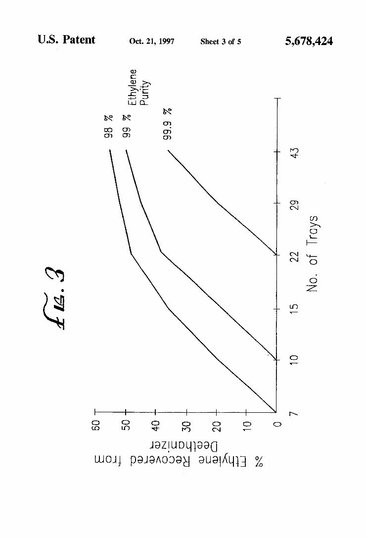
FIG. 3 is a graph of deethanizer-recovered ethylene compared with the number of actual trays required for three levels of ethylene purity desired in the overhead product of the rectified reflux deethanizer of the present invention.
FIG. 4 is a plot of the components ethylene and ethane (Key number 1 on the plot or "C2's") and propylene, propane and butane (Key number 2 of the plot or "C3's--"). The relative vapor compositions of the two keys are plotted against actual tray number for operation of a deethanizer according to the prior art deethanizer described in FIG. 1. A "Condenser" notation indicates the top of the column on the x-axis of the plot. A "Reboiler" notation indicates the bottom of the column on the x-axis of the plot. FIG. 5 is a plot of the components ethylene and ethane
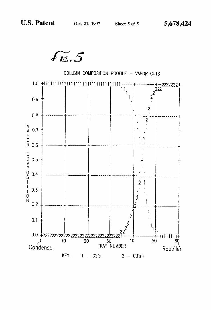
(Key number 1 on the plot or "C2's") and propylene, propane and butane (Key number 2 of the plot or "C3's--"). The relative vapor compositions of the two keys are plotted against actual tray number for operation of a deethanizer according to the prior art deethanizer described in FIG. 2. A "Condenser" notation indicates the top of the column on the x-axis of the plot. A "Reboiler" notation indicates the bottom of the column on the x-axis of the plot.
10
15
20
25
30
35
45
50
55
65
6 DETALED DESCRIPTION OF THE
NVENTION
For the section of the deethanizer from the feed stage to a sidedraw withdrawal stage, the present invention operates similarly to a prior art deethanizer, wherein a sidedraw stream is withdrawn and further fractionated in a C2 splitter to recover ethylene from ethane and a reflux stream is provided to the sidedraw withdrawal stage from the stage above it. The present invention creates above the sidedraw withdrawal stage an additional rectification section at sub stantially the same pressure as the rest of the deethanizer wherein rectification of ethylene from ethane occurs without significant increase in cold utilities in the overhead con denser compared to a deethanizer without the additional rectification section. A comparison of a prior art deethanizer with a low pressure, heat-pumped C2 splitter is compared below with a deethanizer according to the present invention with a low pressure, heat-pumped C2 splitter.
PROR ART DEETHANZER
FIG. 1 is the prior art process comprising columns C100 (a deethanizer with a rectification and stripping section) and C101 (a low pressure, heat pumped C2 splitter). Other equipment noted in FIG. 1 are exchangers E100 (deethanizer reboiler, preferably heated with quench water), E101 (deethanizer overhead condenser, preferably cooled with propylene refrigerant). E102 (deethanizer overhead product partial vaporizer, preferably recovered to demethanizer feed chilling), E103 (C2 splitter heat pump reboiler), E104 (C2 splitter heat recovery reboiler, preferably chilling demetha nizer feed), E105 (coldbox exchanger, preferably recovering process stream chilling), E106 (ethylene refrigeration load, preferably demethanizer feed chilling), E107 (ethane recycle vaporizer), E108 (ethylene refrigerant condenser, propylene refrigerant) and E109 (ethylene refrigerant cooler, propylene refrigerant), and stages S100/S101 (open ethylene refriger ant loop compressor stages, wherein S101 represents two compression stages). Stage S102 (not shown in FIG. 1) is described herein for the purpose of describing a comparative savings in compressor horsepower in the propylene refrig erant compressor, which supplies chilling in exchangers E108 and E109 to the ethylene refrigeration loop. The process streams of FIG. 1 are streams 100 (upper and
lower, i.e. vapor and liquid, streams of demethanized cracked gas), 101 (deethanizer bottoms stream), 102 (deethanizer overhead product), 103 (C2 splitter bottoms product). 104 (top stage vapor stream from the C2 splitter), 105 (lowest pressure stage drum vapor from the open ethylene refrigeration loop), 106 (heat-pumped C2 splitter reflux condensed in C2 splitter reboiler), 107 (highest pres sure stage drum vapor from the open ethylene refrigeration loop), 108 (subcooled ethylene refrigerant loop condensate for C2 splitter reflux), 109 (ethane recycle, i.e. net bottoms product of the C2 splitter) and 110 (net ethylene product from the C2 splitter). Table 1 indicates the stream compositions, rates and conditions for this example. The upper, vapor and lower, liquid streams, streams 100,
from the demethanizer feed a feed stage section in column C100, defined by the upper and lower stages to which they are fed. Herein, the feed section will be referred to as a feed stage. Column C100 comprises 28 actual trays wherein streams 100 enter on trays 11 and 12 (the top tray of column C100 is tray 1). For purposes of column analysis for the detailed examples herein, tray efficiency in the rectification sections about 70 percent and in the stripping sections the tray efficiency is about 60 percent.

5,678.424 7
The condenser exchanger E101 and reboiler exchanger E100 provide cold, refluxing and hot, reboiling utilities to column C100 respectively. The relative amounts of C3's in the overhead product stream, stream 102, and the relative amounts of C2's in the bottom product stream, stream 101, indicate a commercially desirable level of separation of those components. This degree of separation will generally be repeated for the example with the present invention for purposes of comparison and is not a specific limitation of the present invention. The relative amounts of light hydrocar bons as stream components can vary widely depending on the source of the feed generating cracked gas. The duty of exchanger E101 is about 50.9 MMBtu/hr for
column C100 operating at about 240 psia. Stream 101, as indicated on FIG. 1, is preferably further fractionated in a C3 splitter (not shown).
Stream 102 is partially vaporized in exchanger E102 and fed to column C101 operating at about 60 psia, whose overhead stream, stream 104, enters the open refrigeration loop low pressure drum, combines with vaporized ethylene refrigerant to form stream 105, and wherein stream 105 feeds the first stage of the open refrigerant loop, stage S100. The compressed vapor from stage S100 is split, and one portion flows to the second stage of the compressor, stage 101, and the rest, stream 106, is condensed in the C2 splitter reboiler, exchanger E103, and the condensed stream is fed to the top stage of the C2 splitter as reflux. The compressed vapor from stage S102 is condensed in exchangers E107, E108 and E109. A portion of the condensed vapor from stage S102 is withdrawn as a net ethylene product, stream 110, while another portion is subcooled in exchanger E105 for use as column C101 reflux and the last portion of the stream is used as ethylene refrigerant, ultimately flowing to exchanger E106. The net bottoms product of column C101, stream 109, is
relatively pure ethane. Stream 103 contains stream 109, wherein a portion of stream 103 is used for demethanizer feed chilling. The refrigeration resulting from vaporizing the net ethane bottoms product of the C2 splitter is recovered to the ethylene refrigeration loop in exchanger E107. The conceptual operation of this low pressure, heat-pumped C2 splitter is substantially the same for this example and the next describing the present invention. Thus, the operation of the C2 splitter and the open ethylene refrigeration loop will not be discussed for the example of the present invention other than to point out significant differences between the prior art operation and that of the present invention shown in FG, 2.
PRESENT INVENTON DEETHANZER
FIG. 2 is the present invention comprising columns C200 (a deethanizer with a stripping section and a rectification section, wherein the rectification section comprises stages between a feed section and a sidedraw withdrawal stage and an additional rectification section. C200A, comprising stages between the sidedraw withdrawal stage and an over head condenser) and C201 (a low pressure, heat pumped C2 splitter). Other equipment noted in FIG. 2 are exchangers E200 (deethanizer reboiler, preferably heated with quench water), E201 (deethanizer overhead condenser, preferably cooled with propylene refrigerant), E202 (deethanizer sid edraw stream partial vaporize, preferably recovered to demethanizer feed chilling), E203 (C2 splitter heat pump reboiler), E204 (C2 splitter heat recovery reboiler, prefer ably chilling demethanizer feed), E205 (coldbox exchanger, preferably recovering process stream chilling), E206
5
10
15
20
25
35
45
50
55
65
8 (ethylene refrigeration load, preferably demethanizer feed chilling), E207 (ethane recycle vaporizer), E208 (ethylene refrigerant condenser) and E209 (ethylene refrigerant cooler), and stages S200 and S201 (open ethylene refriger ant loop compressor stages, wherein S201 represents two compression stages). Stage S.202 (not shown in FIG. 2) is described hereinfor the purpose of describing a comparative savings in compressor horsepower in the propylene refrig erant compressor, which supplies chilling in exchangers E208 and E209 to the ethylene refrigeration loop. The process streams of FIG. 2 are streams 200 (upper and
lower, i.e. vapor and liquid, streams of demethanized cracked gas), 201 (deethanizer bottoms stream). 202 (sidedraw stream), 203 (deethanizer overhead ethylene product stream). 203A (relatively impure deethanizer over head ethylene product streamfed to the C2 splitter), 204(C2 splitter bottoms product), 205 (top stage vapor stream from the C2 splitter). 206 (lowest pressure stage drum vapor from the open ethylene refrigeration loop), 207 (heat-pumped C2 splitter reflux condensed in C2 splitter reboiler). 208 (highest pressure stage drum vapor from the open ethylene refrigeration loop), 209 (subcooled ethylene refrigerant loop condensate for C2 splitter reflux), 210 (ethane recycle, i.e. net bottoms product of the C2 splitter) and 211 (net ethylene product from the C2 splitter). Table 2 indicates the stream compositions, rates and conditions for this example.
Table 3 is a comparative listing of the duties of the important heat exchangers for the processes shown in FIGS. 1 and 2. Table 4 is a comparative listing of the horsepower of the compression stages described for the embodiments of the prior art example shown in FIG. 1 and the present invention shown in FIG. 2. The horsepower for the propy lene refrigeration compressor is shown as stage S102 for the process of FIG. 1 and as stage S202 for the process of FIG. 2. Stage S102 horsepower is represented as the word “BASE", as the total horsepower for the propylene com pressor comprises many refrigeration loads other than those for C2 splitting. Stage S202 horsepower is represented as the word "BASE-996", indicating a savings of 996 horsepower over the BASE amount for the prior art embodiment of FIG.
The deethanizer, column C200, comprises an additional rectification section, column C200A, wherein the vapor from the sidedraw withdrawal stage enters from the bottom and is rectified to form stream 203 or 203A. Column C200, operating at about 240 psia, comprises about 57 actual trays, wherein feed streams 100 enter on trays 41 and 42 (the top tray of column C200 is the number 1 tray). The sidedraw withdrawal stage is at tray number 30. Stream 203 is the sidedraw stream in FIG. 2 and is directed to a number "1", indicating its continuance on the other side of the figure at the other number "1" and inclusion of the overhead product stream of the deethanizer in the ethylene product drum. The duty required in the deethanizer overhead condenser. exchanger E201 for the degree of separation between streams 201, 202 and 203, as shown in Table 2 for all streams in this example, is about 50.7 MMBtu/hr. The inclusion of stream 203A in FIG. 2 indicates a mode
of operation wherein product specification ethylene in the overhead product stream of column C200 is not desired or cannot be achieved with the deethanizer. All or part of the overhead product stream is then directed as stream 203A to a stage higher in column C201 than stream 202, and the remaining portion of the overhead product stream, stream 203, if any, is directed to the ethylene product drum and recovered as stream 211, as indicated in FIG. 2. Alternatively, stream 203 may simply be used as a lower

5,678.424
grade ethylene product than that obtained from the operation of the C2 splitting. For the present example, stream 203 achieves the avery high ethylene purity at the cost of about 29 additional actual trays to the deethanizer, column C200.
10 "reflux" to the sidedraw withdrawal stage in column C200 from the stage above it is approximately equal to the liquid flow rate of the reflux to the top stage of column C100 in F.G. 1.
In another embodiment of the present invention, significant 5 b equipment cost savings will be made wherein the function of FIG. 3 is a graphical representation of the extent of range
of effective operation of the present invention for the type of exchanger E201 and its associated drum are incorporated o feed described in Table 2 for the upper and lower streams into exchanger E208 and its associated product drum. For 100. As an explanation of the features of FIG. 3, the actual such an embodiment, the vapor stream from the top stage of - trays in the additional rectification section, section C200A. column C200A is mixed with the process stream of the C2 10 y are shown as the axis labeled "No. of Trays". The axis splitter between exchangers E207 and E208, thereby elimi- 66 --- labeled “% Ethylene Recovered from Deethanizer nating an exchanger and a drum. Deethanizer reflux is describes th tage of the ethylene i r and lower
obtained by pumping liquid ethylene from the drum asso- N E. 2. s E.i. ciated with E208 to the top stage of column C200A. 2. The lines labeled "98%", "99%” and '99.95%” indicate Epiti Air ce t t E. the purity of the ethylene obtained in stream 203 by opera E. E. E. E. de een st E. tion of section C200A according to the present invention
t a a th e R CO E. t Othe from fractionation of a cracked gas stream derived from dee E. an Fi SE compare di propane. It will be apparent to the skilled person that a t Ext : GS. the e savings in cola u s further extension of the plot shown in FIG. 3 will permit quals about 2 Pet for the Present investion of the 20 accurate evaluation of the stages necessary for higher recov
prior art design. Table 3 permits comparison of the duties for ery of ethylene to the overhead product stream of the those duties. This utilities reduction is a benefit in addition deethanizer to a substantial reduction in vapor and liquid traffic in the . . rectification section of the C2 splitter, indicating that reduc- The present invention may be advantageously used with tion in column diameter would be recommended. The asso- 25 C2 Spitters of any configuration. The rectification of a ciated reduction in condensing duty in the C2 splitter vapor from the sidedraw withdrawal stage in an additional indicates that a simple overhead condenser or the associated rectification section is critical to the practice of the present equipment for the open refrigeration loop also be reduced in invention. As demonstrated by the comprehensive results size and cost. shown in FIG. 3, the present invention has wide ranging
In addition, it is known by the present invention that the 30 application for fractionation of cracked gases with substan purity of stream 203 or 203A can be such that it's purity is tial savings in equipment and refrigeration utilities costs. about the same specification obtained in the overhead prod- In addition, FIGS. 4 and 5 are included to indicate the uct of the downstream fractionator. Alternatively, the purity change in composition of the vapor streams in columns 100 of stream 203 or 203A can be obtained at any other desired and 200. The pattern of separation of keys 1 and 2 are similar purity and can be recovered either as product or sent to a 35 in FIGS. 4 and 5, although it is evident that the same degree downstream fractionation column for further fractionation. of separation takes place with fewer actual trays for the If a liquid product is obtained from the overhead stream of deethanizer of the present invention, whose operation is the deethanizer, column C200, the balance of condensed shown in FIG. 5, when compared to the number of actual liquid from the overhead condenser is sent back as reflux to trays required for the same separation in the prior art section C200A. It has been found that the liquid flow rate of deethanizer, whose operation is shown in FIG. 4.
TABLE 1.
Stream No. 100 (upri) 100 (lwr) 101 O2 104 109 110
Temp. F. -11 61 108 -32 -05 90 -30 Press. psia 240 240 242 232 59 102 241 Vapor frac 100 0.00 0.00 000 100 100 000 Components Lb-mol/hr
Methane 0.3 0.3 0.6 17 0.6 Ethylene 3.425.9 2938.3 6364.2 17796.1 3.5 6360.7 Ethane 320.6 496.9 0.3 817.2 10.9 809.4 7.8 MAPD 0.7 17.3 18.0 Propylene 143.7 1365.7 1503.1 6.3 6.3 Propane 66.1 847.2 92.6 O.7 0.7 C4's 0. 9.4 9.5
TABLE 2
Stream No. 200 (upr) 200 (lwry 201 202 2O3 205 2O 211
Temp. °F. -11 61 112 -26 -33 -105 90 -30 Press. psia 240 240 253 232 240 59 102 241 Vapor frac 1.OO 0.00 000 000 0.00 OO 100 000 Components
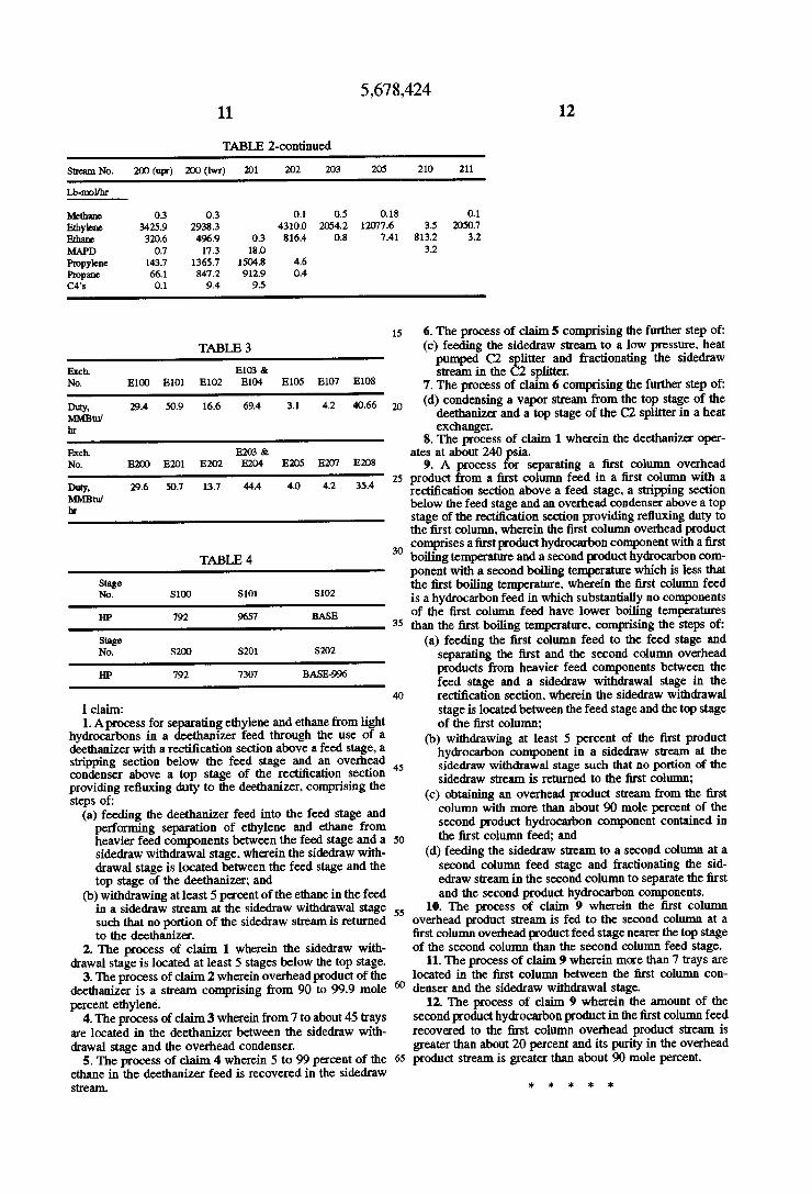
5,678.424 11 12
TABLE 2-continued
Stream No. 200 (upri) 200 (lwr) 201 202 203 205 210 21
Lb-mol/hr
Methane 0.3 0.3 O. 0.5 0.18 0. Ethylene 3425.9 2938.3 4300 2054.2 12077.6 3.5 2050.7 Ethane 320.6 496.9 0.3 816.4 0.8 7.41 813.2 3.2 MAP) 0.7 17.3 18.0 3.2 Propylene 43.7 1365.7 1504.8 4.6 Propane 66.1 847.2 92.9 0.4 C4's 0.1 9.4 9.5
15 6. The process of claim 5 comprising the further step of: TABLE 3 (c) feeding the sidedraw stream to a low pressure, heat
pumped C2 splitter and fractionating the sidedraw Exch. E103 & stream in the C2 splitter. No. E100 E10 E102 E104 E105 E107 E108 7. The process of claim 6 comprising the further step of:
29.4 50.9 16.6 69.4 3.1 42 A0.66 (d) condensing a vapor stream from the top stage of the ity 20 deethanizer and a top stage of the C2 splitter in a heat hr exchanger.
8. The process of claim 1 wherein the deethanizer oper Exch. E2O3 & ates at about 240 psia. No. E2OO E201 E202 E204 E205 E207 E208 9. A process for separating a first column overhead
25 product from a first column feed in a first column with a ity 29.6 50. 13.7 444 40 4.2 35.4 rectification section above a feed stage, a stripping section ht below the feed stage and an overhead condenser above a top
stage of the rectification section providing refluxing duty to the first column, wherein the first column overhead product
30 comprises a first product hydrocarbon component with a first TABLE 4 boiling temperature and a second product hydrocarbon com
ponent with a second boiling temperature which is less that Stage O1 S02 the first boiling temperature, wherein the first column feed No, S100 S1 is a hydrocarbon feed in which substantially no components HP 792 96.57 BASE of the first column feed have lower boiling temperatures
3 than the first boiling temperature, comprising the steps of: Stage (a) feeding the first column feed to the feed stage and No. S200 S20 S2O2 separating the first and the second column overhead HP 792 7307 BASE-996 products from heavier feed components between the
feed stage and a sidedraw withdrawal stage in the o 40 rectification section, wherein the sidedraw withdrawal
I claim: stage is located between the feed stage and the top stage h i. E. for E. yA. from g of the first column; yarocarbons in a deernanizer reed through the use of a (b) withdrawing at least 5 percent of the first product in Sicilitic Yg hydrocarbon component in a sidedraw stream at the SE, above a top stage of Esrectification section EW withdrawal GEFA SA of the
fluxing duty t deethanizer, ising th Sidectaw steam is return e Column; pipe refluxing duty to the deethanizer, comprising the (c) obtaining an overhead product stream from the first (a) feeding the deethanizer feed into the feed stage and column with more than about 90 mole percent of the
performing separation of ethylene and ethane from second product hydrocarbon component contained in heavier feed components between the feed stage and a 50 the first column feed; and sidedraw withdrawal stage, wherein the sidedraw with- (d) feeding the sidedraw stream to a second column at a drawal stage is located between the feed stage and the second column feed stage and fractionating the sid top stage of the deethanizer; and edraw stream in the second column to separate the first
(b) withdrawing at least 5 percent of the ethane in the feed and the second product hydrocarbon components. in a sidedraw stream at the sidedraw withdrawal stage is 10. The process of claim 9 wherein the first column such that no portion of the sidedraw stream is returned to the deethanizer.
2. The process of claim 1 wherein the sidedraw with drawal stage is located at least 5 stages below the top stage.
3. The process of claim 2 wherein overhead product of the deethanizer is a stream comprising from 90 to 99.9 mole percent ethylene.
4. The process of claim3 wherein from 7 to about 45 trays are located in the deethanizer between the sidedraw with drawal stage and the overhead condenser.
5. The process of claim 4 wherein 5 to 99 percent of the ethane in the deethanizer feed is recovered in the sidedraw stream.
65
overhead product stream is fed to the second column at a first column overhead productfeed stage nearer the top stage of the second column than the second column feed stage.
11. The process of claim 9 wherein more than 7 trays are located in the first column between the first column con denser and the sidedraw withdrawal stage.
12. The process of claim 9 wherein the amount of the second product hydrocarbon productin the first column feed recovered to the first column overhead product stream is greater than about 20 percent and its purity in the overhead product stream is greater than about 90 mole percent.
2 : se k sk