new modular f.r.l. units rohs€¦ · · 2015-06-29drain cock with barb fitting (for ø6 x ø4...
TRANSCRIPT

AF40-A
40 mm
Reduced required maintenance space
Better visibility & saferThe bowl is covered with a transparent bowl guard!¡The inside is visible from 360°.¡The bowl is completely protected from
the environment. Safety improved
Max. 46% reduction∗ For AF40-A
Bowl guard
Bowl
New
∗ Body size: 30 or more
AF40
75 mm
35 mm reduction
Adding Bowl Variation !Adding Bowl Variation !
Metal bowlNylon bowl Metal bowl with level gauge
Existing model
Easy replacement of the element
Pressure drop: Max. 50% improvementThe element and the bowl are in one piece. Replacement can be done in hand.
Replacementin hand!
50Energy saving regulator
∗ AF, AW only
Lubricator
LubricatorRegulatorAir Filter Mist Separator
Mist Separator
Regulator
Air Filter
Filter Regulator
FilterRegulator
Doublelayer
design
Metal bow
CAT.EUS40-56C-UK
NewNewRoHSModular F.R.L. Units
Series AC

500 Flow rate L/min [ANR]
AR20-02AR20-02-AAR20-02-ANewNew
AR20-02-ANewNew
AR20-02
0.3
Cond
itions
Outlet pressure[MPa]
� Condensate can be monitored from anywhere.
Series AC
Resin body does not rust.
∗ Except AW
Weight360 g Weight
450 g
Existing model: AW�0
AF40-A AF40
�Light weight: Max. 90 g reduction
�Better visibility: 360°
�Metal related corrosion does not occur.
�Metal related corrosion does not occur.
Air FilterAF
Mist SeparatorAFM
LubricatorAL
Micro Mist SeparatorAFD
Filter RegulatorAW
AW�0-A
AF40-AAF40
Transparent bowl guard
Ap
plic
able
mo
del
∗ Body size: 30 or more
AR AW
Pressure drop: Modular connection
� Inlet pressure: 0.5 MPa �Outlet pressure: 0.3 MPa�Flow rate: 500 L/min (ANR)
� Mount the product by lining up
the mating surface of the new
spacer with bracket.� Insert the retainer into the
spacer bolt and tighten the
nut. (temporary assembling)
� Tighten the nut with the hexagon wrench.
Step q
Step w
Regulator: ARFilter Regulator: AW New Spacer
Tentative tightening
by fingers is possible.
Nut
Spacer with bracket Retainer
Max. 50% improvement
� New spacer can be connected to existing AF, AR, AL, AW series.
� Existing spacer cannot be used for new AR�-A, AW�-A series.
Interchangeable with existing model
Features 1

Series ACModular F.R.L. Units
Series Configuration
Product ModelPort size
INDEX1/8 1/4 3/8 1/2 3/4
Air
Co
mb
inat
ion
P.1
P.7
P.11
P.15
P.19
AC20D-A
AC30D-A
AC40D-A
AC40D-06-A
Filter Regulator + Mist SeparatorAW AFM
AC20C-A
AC25C-A
AC30C-A
AC40C-A
AC40C-06-A
Air Filter + Mist Separator + RegulatorAF AFM AR
AC20B-A
AC25B-A
AC30B-A
AC40B-A
AC40B-06-A
Air Filter + RegulatorAF AR
AC20A-A
AC30A-A
AC40A-A
AC40A-06-A
Filter Regulator + LubricatorAW AL
AC20-A
AC25-A
AC30-A
AC40-A
AC40-06-A
Air Filter + Regulator + LubricatorAF AR AL
AC
AFAR
ALAW
ALAF
ARAF
AFM
ARAW
AFM
AF
AFM
/ AF
DA
RA
LA
WA
ttac
hm
ent
Front matter 1

Series AC
ProductPort size
INDEX1/8 1/4 3/8 1/2 3/4
Air
Filt
er
P.28
AF
Mis
t S
epar
ato
r P.28
AFM
Mic
ro M
ist
Sep
arat
or
P.28
AFD
Reg
ula
tor
P.48
Model
AF20-A
AF30-A
AF40-A
AF40-06-A
AFM20-A
AFM30-A
AFM40-A
AFM40-06-A
AFD20-A
AFD30-A
AFD40-A
AFD40-06-A
AR20-A
AR25-A
AR30-A
AR40-A
AR40-06-A
AR
Series Configuration
Front matter 2

Series ACModular F.R.L. Units
ProductPort size
INDEX1/8 1/4 3/8 1/2 3/4
Lu
bri
cato
r
AL
Filt
er R
egu
lato
r
P.62
AW
Model
AL20-A
AL30-A
AL40-A
AL40-06-A
AW20-A
AW30-A
AW40-A
AW40-06-A
P.56
A system designed to respond quickly and easily to your special ordering needs
Repeat ordersOnce we receive a Simple Special part number from your previous order, we will process the order, manufacture the product, and deliver it to you.
Short lead timesThis system enables us to respond to your special needs, such as additional machining, accessory assembly, or modular unit, and deliver such special products as quickly as standard products.
Simple Specials System
Series Configuration
AC
AFAR
ALAW
ALAF
ARAF
AFM
ARAW
AFM
AF
AFM
/ AF
DA
RA
LA
WA
ttac
hm
ent
Front matter 3
Series AC
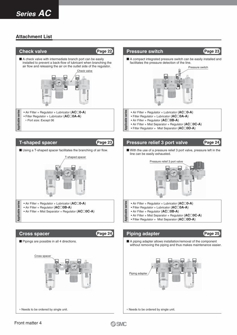
Check valve
T-shaped spacer
Pressure switch
Pressure relief 3 port valve
Cross spacer
Piping adapter
� A check valve with intermediate branch port can be easily installed to prevent a back-flow of lubricant when branching the air flow and releasing the air on the outlet side of the regulator.
Page 22Check valve
(AC�0-A)(AC�0A-A)
∗ Port size: Except 06
App
licab
le s
erie
s
� Using a T-shaped spacer facilitates the branching of air flow.
Page 23T-shaped spacer
(AC�0-A)(AC�0B-A)
(AC�0C-A)
� A compact integrated pressure switch can be easily installed and facilitates the pressure detection of the line.
Page 23Pressure switch
(AC�0-A)(AC�0A-A)
(AC�0B-A)(AC�0C-A)
(AC�0D-A)
� With the use of a pressure relief 3 port valve, pressure left in the line can be easily exhausted.
Page 24
� A piping adapter allows installation/removal of the component without removing the piping and thus makes maintenance easier.
� Pipings are possible in all 4 directions.
Page 25Piping adapterPage 24Cross spacer
∗ Needs to be ordered by single unit. ∗ Needs to be ordered by single unit.
Pressure relief 3 port valve
(AC�0-A)(AC�0A-A)
(AC�0B-A)(AC�0C-A)
(AC�0D-A)
Attachment List
App
licab
le s
erie
s
App
licab
le s
erie
s
App
licab
le s
erie
s
Front matter 4

2 port valve
Modular adapter (E310-U02)
Spacer with bracket (Y300T-A)
Air filter (AF30-A)
Pressure switch with piping adapter
Spacer
Hexagon socket
Uni 1/8 to 1/2
Page 25Pressure switch with piping adapter
∗ Needs to be ordered separately.
Modular adapter
Page 26Accessories (Spacer/Bracket)
∗ Needs to be ordered separately.
Easy modular connections for all equipment!
Related Products
Example) Air filter + 2 port valve
Attachment List
Modular F.R.L. Units Series AC
AC
AFAR
ALAW
ALAF
ARAF
AFM
ARAW
AFM
AF
AFM
/ AF
DA
RA
LA
WA
ttac
hm
ent
Front matter 5
Symbol
+
+
+
+
+
+
+
+
+
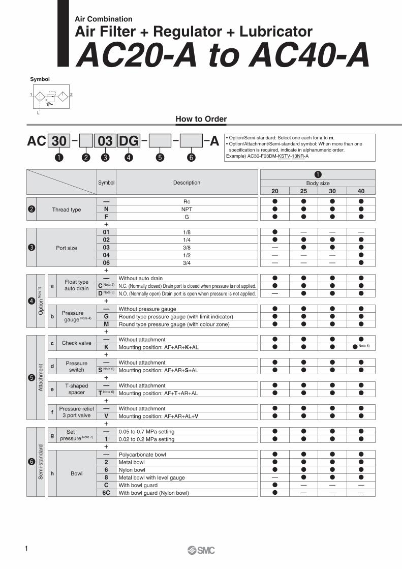
How to Order
Air Combination
Air Filter + Regulator + Lubricator
AC20-A to AC40-A
AC A30q
03e
DGr t yw
q
20
���
25
���
30
���
40
���
Body sizeDescription
RcNPT
G
Symbol
—NF
Thread typew
��———
—��——
—��——
—����
1/81/43/81/23/4
0102030406
Port sizee
r
Atta
chm
ent
Sem
i-sta
ndar
d
��—
���
���
���
—C Note 2)
D Note 3)
Float typeauto draina
Without auto drainN.C. (Normally closed) Drain port is closed when pressure is not applied.N.O. (Normally open) Drain port is open when pressure is not applied.
���
���
���
���
—GM
bWithout pressure gaugeRound type pressure gauge (with limit indicator)Round type pressure gauge (with colour zone)
��
��
��
�� Note 5)
—K
Check valve
Pressureswitch
Setpressure Note 7)
t
cWithout attachmentMounting position: AF+AR+K+AL
��
��
��
��
—S Note 6)d
Without attachmentMounting position: AF+AR+S+AL
��
��
��
��
—T Note 6)
T-shapedspacere
Without attachmentMounting position: AF+T+AR+AL
��
��
��
��
—V
Pressure relief3 port valvef
Without attachmentMounting position: AF+AR+AL+V
��
��
��
��
—1
y
g0.05 to 0.7 MPa setting0.02 to 0.2 MPa setting
���—��
����——
����——
����——
—268C6C
Bowlh
Polycarbonate bowlMetal bowlNylon bowlMetal bowl with level gaugeWith bowl guardWith bowl guard (Nylon bowl)
L
21
Pressuregauge Note 4)
Option/Semi-standard: Select one each for a to m.
specification is required, indicate in alphanumeric order.Example) AC30-F03DM-KSTV-13NR-A
Opt
ion N
ote
1)
1

Air− 5 to 60°C (with no freezing)
1.5 MPa1.0 MPa
0.05 to 0.7 MPa5 μm
Class 1 turbine oil (ISO VG32)Polycarbonate
Relieving type
AC20-A AC25-A AC30-A AC40-A AC40-06-A
1/8, 1/4 1/4, 3/81/8
1/4, 3/8 1/4, 3/8, 1/2
Semi-standard (Steel)
0.39 0.67 1.26 1.43
Standard (Polycarbonate)
AF20-AAR20-AAL20-A
AF30-AAR25-AAL30-A
AF30-AAR30-AAL30-A
AF40-AAR40-AAL40-A
AF40-06-AAR40-06-AAL40-06-A
Model
Component
Port sizePressure gauge port sizeFluidAmbient and fluid temperatureProof pressureMax. operating pressureSet pressure rangeNominal filtration ratingRecommended lubricantBowl materialBowl guardRegulator constructionWeight [kg]
Standard Specifications
+
+
+
+
q
y
��
��
��
��
—3 Note 9)
Lubricatorlubricant
exhaust portj
Without drain cockLubricator with drain cock
��
��
��
��
—N
Exhaustmechanism
kRelieving typeNon-relieving type
��
��
��
��
—R
Flow directionlFlow direction: Left to rightFlow direction: Right to left
�� Note 11)
�� Note 11)
�� Note 11)
�� Note 11)
—Z Note 10)
Pressure unitmName plate and pressure gauge in imperial units: MPaName plate, caution plate for bowl, and pressure gauge in imperial units: psi, °F
��——
�—��
�—��
�—��
—
J Note 8)
W Note 12)
Filterdrain port
i
With drain cockDrain guide 1/8Drain guide 1/4Drain cock with barb fitting (for ø6 x ø4 nylon tube)
Sem
i-sta
ndar
d
20 25 30 40Body size DescriptionSymbol
AC40-AAC20-A
3/4
Note 1) Option G, M are not assembled and supplied loose at the time of shipment.
Note 2) When pressure is not applied, condensate which does not start the auto drain mechanism will be left in the bowl. Releasing the residual condensate before ending operations for the day is recommended.
Note 3) If the compressor is small (0.75 kW, discharge flow is less than 100 L/min[ANR]), air leakage from the drain cock may occur during start of operations. N.C. type is recommended.
Note 4) When the pressure gauge is attached, a 1.0 MPa pressure gauge will be fitted for standard (0.7 MPa) type. 0.4 MPa pressure gauge for 0.2 MPa type.
Note 5) Not available with piping port size: 06Note 6) The bracket position varies depending on the
T-shaped spacer or pressure switch mounting.Note 7) Pressure can be set higher than the
specification pressure in some cases, but use pressure within the specification range.
Note 8) Without a valve functionNote 9) When choosing with W: Filter drain port, the
drain cock of a lubricator will be with barb fittings.
Note 10) For thread type: NPT. MPa and psi are shown together on the
pressure unit. Cannot be used with M: Round pressure
gauge (with colour zone). Available by request for special.
Note 11) �: For thread type: NPT onlyNote 12) The combination of metal bowl: 2 and 8 is
not available.
Air FilterRegulatorLubricator
0.82
AC40 A
Air Combination Series AC20-A to AC40-A
AC
AFAR
ALAW
ALAF
ARAF
AFM
ARAW
AFM
AF
AFM
/ AF
DA
RA
LA
WA
ttac
hm
ent
2

Pressure Characteristics (Representative values) Conditions: Inlet pressure 0.7 MPa, Outlet pressure 0.2 MPa, Flow rate 20 L/min (ANR)
Flow-rate Characteristics (Representative values) Condition: Inlet pressure 0.7 MPa
0.1
0.15
0.2
0.25
0.3
0 0.1 0.2 0.3 0.4 0.5 0.6 0.7 0.8 0.9 1 1.1
Out
let p
ress
ure
[MP
a]
Inlet pressure [MPa]
AC20-A
0.1
0.15
0.2
0.25
0.3
0 0.1 0.2 0.3 0.4 0.5 0.6 0.7 0.8 0.9 1 1.1
Out
let p
ress
ure
[MP
a]
Inlet pressure [MPa]
AC25-A
0.1
0.15
0.2
0.25
0.3
0 0.1 0.2 0.3 0.4 0.5 0.6 0.7 0.8 0.9 1 1.1
Out
let p
ress
ure
[MP
a]
Inlet pressure [MPa]
AC30-A
0.1
0.15
0.2
0.25
0.3
0 0.1 0.2 0.3 0.4 0.5 0.6 0.7 0.8 0.9 1 1.1
Out
let p
ress
ure
[MP
a]
Inlet pressure [MPa]
AC40-A/AC40-06-A
0
0.1
0.2
0.3
0.4
0.5
0.6
0 200 400 600 800
Out
let p
ress
ure
[MP
a]
Flow rate L/min [ANR]
AC20-A Rc1/4
0
0.1
0.2
0.3
0.4
0.5
0.6
0 500 1000 1500O
utle
t pre
ssur
e [M
Pa]
Flow rate L/min [ANR]
AC25-A Rc3/8
0
0.1
0.2
0.3
0.4
0.5
0.6
0 500 1000 1500
Out
let p
ress
ure
[MP
a]
Flow rate L/min [ANR]
AC30-A Rc3/8
0
0.1
0.2
0.3
0.4
0.5
0.6
0 1000 2000 3000
Out
let p
ress
ure
[MP
a]
Flow rate L/min [ANR]
AC40-A Rc1/2
0
0.1
0.2
0.3
0.4
0.5
0.6
0 1000 2000 3000 4000
Out
let p
ress
ure
[MP
a]
Flow rate L/min [ANR]
AC40-06-A Rc3/4
Set pointSet pointSet point
Set point
Series AC20-A to AC40-A
3

Specific Product Precautions
Selection
1. When releasing air at the intermediate position using a T-shaped spacer on the inlet side of the lubricator, lubricant may back flow. Therefore, releasing air that does not contain traces of lubricant is not possible.To release air that does not contain traces of lubricant, use a check valve (Series AKM) on the inlet side of the lubricator to prevent a backflow of the lubricant.
2. If a pressure relief 3 port valve is mounted on the inlet side of the lubricator, causing a backflow of air, it can result in a back-flow of oil or damage to internal parts. Please do not use it in this fashion. Please, locate it on the outlet side of the lu-bricator.
3. An F.R.L. unit shipped from the plant has its model number la-beled. However, components that are combined together dur-ing the distribution process do not have a label on them.
CautionPiping
1. When mounting a check valve, make sure the arrow (IN side) points in the correct direction of air flow.
Warning
Air Supply
1. Use an air filter with 5 μm or less filtration rating on the inlet side of the valve to avoid any damage to the seat caused by dust when mounting a pressure relief 3 port valve on the inlet side.
Caution
Mounting/Adjustment
1. When the bowl is installed on the air filter, filter regulator, lubri-cator, mist separator, or micro mist separator, install them so that the lock button lines up to the groove of the front (or the back) of the body to avoid drop or damage of the bowl.
Caution
Be sure to read before handling. Refer to back cover for Safety Instructions, “Handling Precautions for SMC Products” (M-E03-3) and the Operation Manual for F.R.L. Precautions.
Lock button
Air Combination Series AC20-A to AC40-A
AC
AFAR
ALAW
ALAF
ARAF
AFM
ARAW
AFM
AF
AFM
/ AF
DA
RA
LA
WA
ttac
hm
ent
4

M5 x 0.8
B
1/8
B
1/8
B
B B B
1/4
B
1/4
Barb fitting Applicable tubing: T06041/4
B B
Thread type/Rc, G: ø10 One-touch fittingThread type/NPT: ø3/8" One-touch fitting
B
B
U
S
R
OUTIN
U
SR
ANF
BC
IN OUT
P2
(Pressure gauge port size)
Pressure gauge(Option)
J
J M
VQ
2
Q1
Q1
2 x P1(Port size)
Cle
aran
ce fo
r m
aint
enan
ceG
ANF
BC
P2
(Pressure gauge port size)
E
VQ1
Q1
MJ
J
Pressure gauge(Option)
Cle
aran
ce fo
r m
aint
enan
ceG
2 x P1(Port size)
H H
Drain
Drain
Width across flats 14 Width across
flats 14
N.C.: GrayN.O.: Black
Width across flats 17
Width across flats 17
Width across flats 17
Metal bowl with drain guide Drain cock with barb fittingWith drain guideMetal bowl with
level gaugeMetal bowl with level gauge,
with drain guideMetal bowlOptional/Semi-standard specifications
Dimensions
Applicable model AC25-A to AC40-06-A
With drain guide Metal bowl with drain guideMetal bowlWith auto drain (N.C.)Optional/Semi-standard specifications
Dimensions
Applicable model AC20-A AC25-A to AC40-06-A
With auto drain (N.O./N.C.)
Dimensions
AC20-A AC25-A to AC40-06-A
Model
Semi-standard specificationsOptional specifications
Round type pressure gauge
Hø37.5
ø37.5
ø37.5
ø42.5
ø42.5
J58.5
58.5
65
72
72
Hø37.5
ø37.5
ø37.5
ø42.5
ø42.5
J59.5
59.5
66
72
72
B104.9
156.8
156.8
186.9
188.9
B—
123.6
123.6
155.6
157.6
B 91.4
121.9
121.9
153.9
155.9
Round type pressuregauge (with colour zone)
Withauto drain
Withbarb fitting
Withdrain guide
B 87.4
117.6
117.6
149.6
151.6
Metal bowl
B 93.9
122.1
122.1
154.1
156.1
Metal bowl with drain guide
B—
137.6
137.6
169.6
171.6
Metal bowl with level gauge
B—
142.1
142.1
174.1
176.1
Metal bowl with level gauge, with drain guide
AC20-AAC25-AAC30-AAC40-AAC40-06-A
Model
Standard specifications
Bracket mountP1 P2
1/8, 1/4
1/4, 3/8
1/4, 3/8
1/4, 3/8, 1/2
3/4
1/8
1/8
1/8
1/8
1/8
A
126.4
167.4
167.4
220.4
235.4
B
87.6
115.1
115.1
147.1
149.1
C
35.9
38.1
38.1
39.8
37.8
E
—
30
30
38.4
38.4
F
41.6
55.1
55.1
72.6
77.6
G
60
80
80
110
110
J
23.4
30.5
30.5
36.1
39.6
M30
41
41
50
50
N43.2
57.2
57.2
75.2
80.2
Q1
24
35
35
40
40
Q2
33
—
—
—
—
R5.5
7
7
9
9
S12
14
14
18
18
U3.5
4
4
5
5
V29
41
41
48
48
AC20-AAC25-AAC30-AAC40-AAC40-06-A
Series AC20-A to AC40-A
5

AC
AFAR
ALAW
ALAF
ARAF
AFM
ARAW
AFM
AF
AFM
/ AF
DA
RA
LA
WA
ttac
hm
ent
6

Symbol
+
+
+
+
+
+
+
+
+
AC A A30q
03e
DGr t yw
���
���
���
��—
���
���
��
��
�� Note 5)
��
��
��
��
��
��
���
���
���
��———
—��——
—����
20 30 40Body sizeDescription
RcNPT
G
Symbol
—NF
—C Note 2)
D Note 3)
Thread type�w
1/81/43/81/23/4
0102030406
Port size�e
aWithout auto drainN.C. (Normally closed) Drain port is closed when pressure is not applied.N.O. (Normally open) Drain port is open when pressure is not applied.
—GM
bWithout pressure gaugeRound type pressure gauge (with limit indicator)Round type pressure gauge (with colour zone)
—K
�
�
t
�
cWithout attachmentMounting position: AW+K+AL
—S Note 6)d
Without attachmentMounting position: AW+S+AL
—V
eWithout attachmentMounting position: AW+AL+V
q
—1
y
f0.05 to 0.7 MPa setting0.02 to 0.2 MPa setting
—
J Note 8)
W Note 12)
Filterregulatordrain port
h
With drain cockDrain guide 1/8Drain guide 1/4Drain cock with barb fitting (for ø6 x ø4 nylon tube)
—268C6C
Bowlg
Polycarbonate bowlMetal bowlNylon bowlMetal bowl with level gaugeWith bowl guardWith bowl guard (Nylon bowl)
��
��
��
���—��
����——
����——
��——
�—��
�—��
L
21
How to Order
Atta
chm
ent
Sem
i-sta
ndar
d
r
Float typeauto drain
Check valve
Pressureswitch
Pressure relief3 port valve
Pressuregauge Note 4)
Setpressure Note 7)
a to l.ption/Attachment/Semi-standard symbol: When more than one
specification is required, indicate in alphanumeric order.Example) AC30A-F03DM-KSV-13NR-A
Air Combination
Filter Regulator + Lubricator
AC20A-A to AC40A-AO
ptio
n Not
e 1)
7

Standard Specifications
+
+
+
Air
– 5 to 60°C (with no freezing)
1.5 MPa
1.0 MPa
5 μm
Class 1 turbine oil (ISO VG32)
Polycarbonate
Relieving type
Semi-standard (Steel)
0.33
Standard (Polycarbonate)
0.05 to 0.7 MPa
0.66 1.22 1.34
Model
Component
Port size
Pressure gauge port size
Fluid
Ambient and fluid temperature
Proof pressure
Maximum operating pressure
Set pressure range
Nominal filtration rating
Recommended lubricant
Bowl material
Bowl guard
Regulator construction
Weight [kg]
Filter Regulator
Lubricator
1/8
AC40A-06-A
AW40-06-A
AL40-06-A
3/4
AC40A-A
AW40-A
AL40-A
1/4, 3/8, 1/2
AC30A-A
AW30-A
AL30-A
1/4, 3/8
AC20A-A
AW20-A
AL20-A
1/8, 1/4
AC40A-A
AC20A-A
y
—3 Note 9)i
Without drain cockLubricator with drain cock
—N
jRelieving typeNon-relieving type
—R
kFlow direction: Left to rightFlow direction: Right to left
—Z Note 10)l
Name plate and pressure gauge in imperial units: MPaName plate, caution plate for bowl, and pressure gauge in imperial units: psi, °F
DescriptionSymbol
��
��
��
��
��
��
��
��
��
�� Note 11)
�� Note 11)
�� Note 11)
20 30 40Body size
�q
Note 1) Option G, M are not assembled and supplied loose at the time of shipment.
Note 2) When pressure is not applied, condensate which does not start the auto drain mechanism will be left in the bowl. Releasing the residual condensate before ending operations for the day is recommended.
Note 3) If the compressor is small (0.75 kW, discharge flow is less than 100 L/min[ANR]), air leakage from the drain cock may occur during start of operations. N.C. type is recommended.
Note 4) When the pressure gauge is attached, a 1.0 MPa pressure gauge will be fitted for standard (0.7 MPa) type. 0.4 MPa pressure gauge for 0.2 MPa type.
Note 5) Not available with piping port size: 06Note 6) The bracket position varies depending on
the pressure switch mounting.Note 7) Pressure can be set higher than the
specification pressure in some cases, but use pressure within the specification range.
Note 8) Without a valve function
Note 9) When choosing with W: Filter regulator drain port, the drain cock of a lubricator will be with barb fitting.
Note 10) For thread type: NPT. MPa and psi are shown together on the
pressure unit. Cannot be used with M: Round pressure
gauge (with colour zone). Available by request for special.
Note 11) �: For thread type: NPT onlyNote 12) The combination of metal bowl: 2 and 8 is
not available.
Sem
i-sta
ndar
d
Lubricatorlubricant
exhaust port
Exhaustmechanism
Flow direction
Pressure unit
Air Combination Series AC20A-A to AC40A-A
AC
AFAR
ALAW
ALAF
ARAF
AFM
ARAW
AFM
AF
AFM
/ AF
DA
RA
LA
WA
ttac
hm
ent
8

1/8
B
B B B
1/4
B
1/4
M5 x 0.8
B
1/8
B
B
1/4
B
Barb fitting Applicable tubing: T0604
B
B
UR
S
U
Cle
aran
ce fo
r m
aint
enan
ceG
S
R
OUTIN
AF
P2
(Pressure gauge port size)
BC
IN OUT
Pressure gauge(Option)
JMJ
2 x P1
(Port size)
VQ
2Q1
Q1
Cle
aran
ce fo
r m
aint
enan
ceG
H
BC
FA
P2
(Pressure gauge port size)
Pressure gauge(Option)
JJ M
VQ1
Q1
2 x P1
(Port size)
EH
Drain
Drain
Width across flats 14 Width across
flats 14
N.C.: GrayN.O.: Black
Thread type/Rc, G: ø10 One-touch fittingThread type/NPT: ø3/8" One-touch fitting
Width across flats 17
Width across flats 17
Width across flats 17
Note) The total length of C dimension is the length when the filter regulator knob is unlocked.
Model
Semi-standard specificationsOptional specifications
Round type pressure gauge
Hø37.5
ø37.5
ø42.5
ø42.5
J58.5
65
72
72
Hø37.5
ø37.5
ø42.5
ø42.5
J59.5
66
72
72
B104.9
156.8
186.9
188.9
B—
123.6
155.6
157.6
B 91.4
121.9
153.9
155.9
B 87.4
117.6
149.6
151.6
B 93.9
122.1
154.1
156.1
B—
137.6
169.6
171.6
B—
142.1
174.1
176.1
Round type pressure gauge (with colour zone)
With auto drain
With barb fitting
With drain guide
Metal bowl Metal bowlwith drain guide
Metal bowl with level gauge
Metal bowl with level gauge, with drain guide
AC20A-AAC30A-AAC40A-AAC40A-06-A
Metal bowl with drain guide Drain cock with barb fittingWith drain guideMetal bowl
with level gaugeMetal bowl with level gauge,
with drain guideMetal bowlOptional/Semi-standard specifications
Dimensions
Applicable model AC30A-A to AC40A-06-A
With drain guide Metal bowl with drain guideMetal bowlWith auto drain (N.C.)Optional/Semi-standard specifications
Dimensions
Applicable model AC20A-A AC30A-A to AC40A-06-A
With auto drain (N.O./N.C.)
Dimensions
AC20A-A AC30A-A to AC40A-06-A
Model
Standard specifications
Bracket mountP1 P2
1/8, 1/4
1/4, 3/8
1/4, 3/8, 1/2
3/4
1/8
1/8
1/8
1/8
A
83.2
110.2
145.2
155.2
B
87.6
115.1
147.1
149.1
C Note)
67.4
83.5
100
101.5
E
—
30
38.4
38.4
F
41.6
55.1
72.6
77.6
G
60
80
110
110
J
23.4
30.5
36.1
39.6
M30
41
50
50
Q1
24
35
40
40
Q2
33
—
—
—
R 5.5
7
9
9
S12
14
18
18
U3.5
4
5
5
V29
41
48
48
AC20A-AAC30A-AAC40A-AAC40A-06-A
Series AC20A-A to AC40A-A
9

AC
AFAR
ALAW
ALAF
ARAF
AFM
ARAW
AFM
AF
AFM
/ AF
DA
RA
LA
WA
ttac
hm
ent
10

+
+
+
Air Combination
Air Filter + Regulator
AC20B-A to AC40B-A
�qDescription
RcNPT
G
Symbol
—NF
—C Note 2)
D Note 3)
Thread type
Float typeauto drain
�w
1/81/43/81/23/4
0102030406
Port size�e
�r
aWithout auto drainN.C. (Normally closed) Drain port is closed when pressure is not applied.N.O. (Normally open) Drain port is open when pressure is not applied.
—GM
bWithout pressure gaugeRound type pressure gauge (with limit indicator)Round type pressure gauge (with colour zone)
20
���
25
���
30
���
40
���
��———
—��——
—��——
—����
��—
���
���
���
���
���
���
���
Body size
Symbol
+
+
+
+
+
—S Note 5)
T Note 5)T-shaped spacer
Pressureswitch
�t
cWithout attachmentMounting position: AF+S+ARMounting position: AF+T+AR
���
���
���
���
—V
V1 Note 6)
dWithout attachmentMounting position: AF+AR+VMounting position: V+AF+AR
���
���
���
���
��
��
��
��
—1
�y
e0.05 to 0.7 MPa setting0.02 to 0.2 MPa setting
��——
�—��
�—��
�—��
—
J Note 8)
W Note 11)
Filterdrain port
g
With drain cockDrain guide 1/8Drain guide 1/4Drain cock with barb fitting (for ø6 x ø4 nylon tube)
���—��
����——
����——
����——
—268C6C
Bowlf
Polycarbonate bowlMetal bowlNylon bowlMetal bowl with level gaugeWith bowl guardWith bowl guard (Nylon bowl)
AC B A30q
03e
DGr t yw
L
21
How to Order
Sem
i-sta
ndar
dA
ttach
men
t
Pressuregauge Note 4)
Pressure relief3 port valve
Setpressure Note 7)
a to j.Option/Attachment/Semi-standard symbol: When more than one specification is required, indicate in alphanumeric order.
Example) AC30B-F03DM-SV-1NR-A
Opt
ion N
ote
1)
11

+
+
Standard Specifications
1/8
Air
– 5 to 60°C (with no freezing)
1.5 MPa
1.0 MPa
5 μm
Polycarbonate
Relieving type
Semi-standard (Steel)
0.27
Standard (Polycarbonate)
0.42 0.57 0.79 0.90
Model
Component
Port size
Pressure gauge port size
Fluid
Ambient and fluid temperature
Proof pressure
Maximum operating pressure
Set pressure range
Nominal filtration rating
Bowl material
Bowl guard
Regulator construction
Weight [kg]
Air Filter
Regulator
AC25B-A
AF30-A
AR25-A
1/4, 3/8
AC30B-A
AF30-A
AR30-A
1/4, 3/8
AC40B-A
AF40-A
AR40-A
1/4, 3/8, 1/2
AC40B-06-A
AF40-06-A
AR40-06-A
3/4
AC20B-A
AF20-A
AR20-A
1/8, 1/4
0.05 to 0.7 MPa
�y
��
��
��
��
—N
hRelieving typeNon-relieving type
��
��
��
��
—R
Flow directioniFlow direction: Left to rightFlow direction: Right to left
�� Note 10)
�� Note 10)
�� Note 10)
�� Note 10)
—Z Note 9)
Pressure unitjName plate and pressure gauge in imperial units: MPaName plate, caution plate for bowl, and pressure gauge in imperial units: psi, °F
20 25 30 40Body sizeDescriptionSymbol
�q
Note 1) Option G, M are not assembled and supplied loose at the time of shipment.
Note 2) When pressure is not applied, condensate which does not start the auto drain mechanism will be left in the bowl. Releasing the residual condensate before ending operations for the day is recommended.
Note 3) If the compressor is small (0.75 kW, discharge flow is less than 100 L/min[ANR]), air leakage from the drain cock may occur during start of operations. N.C. type is recommended.
Note 4) When the pressure gauge is attached, a 1.0 MPa pressure gauge will be fitted for standard (0.7 MPa) type. 0.4 MPa pressure gauge for 0.2 MPa type.
Note 5) The bracket position varies depending on the T-shaped spacer or pressure switch mounting.
Note 6) Make sure that the outlet pressure is released to atmospheric pressure using a pressure gauge.For V1 specification, use the regulator with a set pressure of 0.15 MPa or more to ensure the pressure release.
Note 7) Pressure can be set higher than the specification pressure in some cases, but use pressure within the specification range.
Note 8) Without a valve functionNote 9) For thread type: NPT. MPa and psi are shown together on the
pressure unit. Cannot be used with M: Round pressure
gauge (with colour zone). Available by request for special.
Note 10) �: For thread type: NPT onlyNote 11) The combination of metal bowl: 2 and 8 is
not available.
Sem
i-sta
ndar
d
Exhaustmechanism
AC40B-AAC20B-A
Air Combination Series AC20B-A to AC40B-A
AC
AFAR
ALAW
ALAF
ARAF
AFM
ARAW
AFM
AF
AFM
/ AF
DA
RA
LA
WA
ttac
hm
ent
12

1/8
B
B B B
1/4
B
1/4
M5 x 0.8
B
1/8
B
Thread type/Rc, G: ø10 One-touch fittingThread type/NPT: ø3/8" One-touch fitting
B
1/4
B
Barb fitting Applicable tubing: T0604
B
B
U
R
S
OUTINH
U
R
S
OUT
AF
BC
P2
(Pressure gauge port size)
Q2
VQ1
Q1
MJ
J
Pressure gauge(Option)
2 x P1
(Port size)
Cle
aran
ce fo
r m
aint
enan
ceG
AF
BC
P2
(Pressure gauge port size)
VQ1
Q1
MJ
JPressure gauge(Option)
2 x P1
(Port size)
Cle
aran
ce fo
r m
aint
enan
ceG
E
H
IN
Drain
Drain
Width across flats 14 Width across
flats 14
Width across flats 17
Width across flats 17
Width across flats 17
N.C.: GrayN.O.: Black
Drain cock with barb fittingWith drain guideOptional/Semi-standard specifications
Dimensions
Applicable model AC25B-A to AC40B-06-A
With drain guide Metal bowl with drain guideMetal bowlWith auto drain (N.C.)Optional/Semi-standard specifications
Dimensions
Applicable model AC20B-A AC25B-A to AC40B-06-A
With auto drain (N.O./N.C.)
Model
Semi-standard specificationsOptional specifications
Round type pressure gauge
Hø37.5
ø37.5
ø37.5
ø42.5
ø42.5
J58.5
58.5
65
72
72
Hø37.5
ø37.5
ø37.5
ø42.5
ø42.5
J59.5
59.5
66
72
72
B104.9
156.8
156.8
186.9
188.9
B—
123.6
123.6
155.6
157.6
B 91.4
121.9
121.9
153.9
155.9
B 87.4
117.6
117.6
149.6
151.6
B 93.9
122.1
122.1
154.1
156.1
B—
137.6
137.6
169.6
171.6
B—
142.1
142.1
174.1
176.1
Round type pressuregauge (with colour zone)
Withauto drain
Withbarb fitting
Withdrain guide
Metal bowl Metal bowl with drain guide
Metal bowl with level gauge
Metal bowl with level gauge, with drain guide
AC20B-AAC25B-AAC30B-AAC40B-AAC40B-06-A
Dimensions
AC20B-A AC25B-A to AC40B-06-A
Model
Standard specifications
Bracket mountP1 P2
1/8, 1/4
1/4, 3/8
1/4, 3/8
1/4, 3/8, 1/2
3/4
1/8
1/8
1/8
1/8
1/8
A
83.2
110.2
110.2
145.2
155.2
B
87.6
115.1
115.1
147.1
149.1
C
23.5
23.5
27
33.5
33.5
E
—
30
30
38.4
38.4
F
41.6
55.1
55.1
72.6
77.6
G
25
35
35
40
40
J
23.4
30.5
30.5
36.1
39.6
M30
41
41
50
50
Q1
24
35
35
40
40
Q2
33
—
—
—
—
R5.5
7
7
9
9
S12
14
14
18
18
U3.5
4
4
5
5
V29
41
41
48
48
AC20B-AAC25B-AAC30B-AAC40B-AAC40B-06-A
Metal bowl with drain guideMetal bowl
with level gaugeMetal bowl with level gauge,
with drain guideMetal bowl
Series AC20B-A to AC40B-A
13

AC
AFAR
ALAW
ALAF
ARAF
AFM
ARAW
AFM
AF
AFM
/ AF
DA
RA
LA
WA
ttac
hm
ent
14

�w
�e
�r
�t
Air Combination
Air Filter + Mist Separator + Regulator
AC20C-A to AC40C-A
+
+
+
+
+
+
+
+
+
Description
RcNPT
G
Symbol
—NF
—GM
—CNote 2)
DNote 3)
0102030406
Thread type
Port size
—S Note 5)
T Note 5)T-shaped spacer
Float typeauto drain
1/81/43/81/23/4
Without auto drainN.C. (Normally closed) Drain port is closed when pressure is not applied.N.O. (Normally open) Drain port is open when pressure is not applied.
Without pressure gaugeRound type pressure gauge (with limit indicator)Round type pressure gauge (with colour zone)
Atta
chm
ent
b
a
c
—V
V1 Note 6)
d
25
���
—��——
���
���
���
30
���
—��——
���
���
���
40
���
—����
���
���
���
20
���
��———
���
���
���
���
��—
���
���
Body size
�q
Without attachmentMounting position: AF+AFM+S+ARMounting position: AF+AFM+T+AR
Without attachmentMounting position: AF+AFM+AR+VMounting position: V+AF+AFM+AR
Symbol
�y
—268C6C
FilterMist separator
drain port
Bowl
—1
—N
Exhaustmechanism
—
J Note 8)
W Note 11)
With drain cockDrain guide 1/8Drain guide 1/4Drain cock with barb fitting (for ø6 x ø4 nylon tube)
Sem
i-sta
ndar
d f
e
h
�—��
����——
��
��
�—��
����——
��
��
�—��
����——
��
��
��——
���—��
��
��
Polycarbonate bowlMetal bowlNylon bowlMetal bowl with level gaugeWith bowl guardWith bowl guard (Nylon bowl)
0.05 to 0.7 MPa setting0.02 to 0.2 MPa setting
Relieving typeNon-relieving type
g
AC C A30q
03e
DGr t yw
LL
21
How to Order
Pressuregauge Note 4)
Pressureswitch
Pressure relief3 port valve
Setpressure Note 7)
a to j.Option/Attachment/Semi-standard symbol: When more than one specification is required, indicate in alphanumeric order.
Example) AC30C-F03DM-SV-1NR-A
Opt
ion N
ote
1)
15

AC40C-AAC20C-A
DescriptionSymbol
25 30 4020Body size
�q
1/8
Air
– 5 to 60°C (with no freezing)
1.5 MPa
1.0 MPa
0.05 MPa
0.05 to 0.7 MPa
AF: 5 μm, AFM: 0.3 μm (99.9% filtered particle size)
MAX 1.0 mg/m3 (ANR) (≈ 0.8 ppm) Note 2) Note 3)
Polycarbonate
Relieving type
450
0.67
200
Semi-standard (Steel)
0.38
Standard (Polycarbonate)
450
0.82
1100
1.26
1100
1.42
Model
Component
Port size
Pressure gauge port size
Fluid
Ambient and fluid temperature
Proof pressure
Maximum operating pressure
Minimum operating pressure
Set pressure range
Nominal filtration rating
Outlet side oil mist concentration
Rated flow [L/min (ANR)] Note 1)
Bowl material
Bowl guard
Regulator construction
Weight [kg]
Air Filter
Mist Separator
Regulator
AC40C-06-A
AF40-06-A
AFM40-06-A
AR40-06-A
3/4
AC40C-A
AF40-A
AFM40-A
AR40-A
1/4, 3/8, 1/2
AC30C-A
AF30-A
AFM30-A
AR30-A
1/4, 3/8
AC25C-A
AF30-A
AFM30-A
AR25-A
1/4, 3/8
AC20C-A
AF20-A
AFM20-A
AR20-A
1/8, 1/4
Note 1) Conditions: Mist separator inlet pressure: 0.7 MPa; The rated flow varies depending on the inlet pressure. Keep the air flow within the rated flow to prevent an outflow of lubricant to the outlet side.
Note 2) When the compressor oil mist discharge concentration is 30 mg/m3 (ANR).Note 3) Bowl O-ring and other O-rings are slightly lubricated.
Standard Specifications
y—
Z Note 9)Pressure unit
Sem
i-sta
ndar
d
j�
� Note 10)
�� Note 10)
�� Note 10)
�� Note 10)
Name plate and pressure gauge in imperial units: MPaName plate, caution plate for bowl, and pressure gauge in imperial units: psi, °F
—R
Flow directioni��
��
��
��
Flow direction: Left to rightFlow direction: Right to left
+
Note 1) Option G, M are not assembled and supplied loose at the time of shipment.
Note 2) When pressure is not applied, condensate which does not start the auto drain mechanism will be left in the bowl. Releasing the residual condensate before ending operations for the day is recommended.
Note 3) If the compressor is small (0.75 kW, discharge flow is less than 100 L/min[ANR]), air leakage from the drain cock may occur during start of operations. N.C. type is recommended.
Note 4) When the pressure gauge is attached, a 1.0 MPa pressure gauge will be fitted for standard (0.7 MPa) type. 0.4 MPa pressure gauge for 0.2 MPa type.
Note 5) The bracket position varies depending on the T-shaped spacer or pressure switch mounting.
Note 6) Make sure that the outlet pressure is released to atmospheric pressure using a pressure gauge.For V1 specification, use the regulator with a set pressure of 0.15 MPa or more to ensure the pressure release.
Note 7) Pressure can be set higher than the specification pressure in some cases, but use pressure within the specification range.
Note 8) Without a valve functionNote 9) For thread type: NPT. MPa and psi are shown together on the
pressure unit. Cannot be used with M: Round pressure
gauge (with colour zone). Available by request for special.
Note 10) �: For thread type: NPT onlyNote 11) The combination of metal bowl: 2 and 8 is
not available.
Air Combination Series AC20C-A to AC40C-A
AC
AFAR
ALAW
ALAF
ARAF
AFM
ARAW
AFM
AF
AFM
/ AF
DA
RA
LA
WA
ttac
hm
ent
16

1/8
B
B B B
1/4
B
1/4
B
M5 x 0.8
B
1/8
B
Thread type/Rc, G: ø10 One-touch fittingThread type/NPT: ø3/8" One-touch fitting
B
1/4
B
Barb fitting Applicable tubing: T0604
B
U
R
S
Drain Drain
OUT
U
S
R
Drain Drain
OUTIN
ANF
IN
BCV
Q2Q1
Q1
MJJ
2 x P1
(Port size)
P2
(Pressure gauge port size)
Cle
aran
ce fo
r m
aint
enan
ceG
Pressure gauge(Option)
ANF
B
P2
(Pressure gauge port size)
J
J M
VQ1
Q1
HE
Cle
aran
ce fo
r m
aint
enan
ceG
2 x P1
(Port size)
C
Pressure gauge(Option)
H
Width across flats 14 Width across
flats 14
Width across flats 17
Width across flats 17
Width across flats 17
N.C.: GrayN.O.: Black
Drain cock with barb fittingWith drain guideOptional/Semi-standard specifications
Dimensions
Applicable model AC25C-A to AC40C-06-A
With drain guide Metal bowl with drain guideMetal bowlWith auto drain (N.C.)Optional/Semi-standard specifications
Dimensions
Applicable model AC20C-A AC25C-A to AC40C-06-A
With auto drain (N.O./N.C.)
Dimensions
AC20C-A AC25C-A to AC40C-06-A
Model
Standard specifications
Bracket mountP1 P2
1/8, 1/4
1/4, 3/8
1/4, 3/8
1/4, 3/8, 1/2
3/4
1/8
1/8
1/8
1/8
1/8
A
126.4
167.4
167.4
220.4
235.4
B
87.6
115.1
115.1
147.1
149.1
C
23.5
23.5
27
33.5
33.5
E
—
30
30
38.4
38.4
F
41.6
55.1
55.1
72.6
77.6
G
40
50
50
75
75
J
23.4
30.5
30.5
36.1
39.6
M30
41
41
50
50
N43.2
57.2
57.2
75.2
80.2
Q1
24
35
35
40
40
Q2
33
—
—
—
—
R5.5
7
7
9
9
S12
14
14
18
18
U3.5
4
4
5
5
V29
41
41
48
48
AC20C-AAC25C-AAC30C-AAC40C-AAC40C-06-A
Model
Semi-standard specificationsOptional specifications
Round type pressure gauge
Hø37.5
ø37.5
ø37.5
ø42.5
ø42.5
J58.5
58.5
65
72
72
Hø37.5
ø37.5
ø37.5
ø42.5
ø42.5
J59.5
59.5
66
72
72
B104.9
156.8
156.8
186.9
188.9
B—
123.6
123.6
155.6
157.6
B 91.4
121.9
121.9
153.9
155.9
B 87.4
117.6
117.6
149.6
151.6
B 93.9
122.1
122.1
154.1
156.1
B—
137.6
137.6
169.6
171.6
B—
142.1
142.1
174.1
176.1
Round type pressure gauge (with colour zone)
With auto drain
With barb fitting
With drain guide
AC20C-AAC25C-AAC30C-AAC40C-AAC40C-06-A
Metal bowl with drain guide Metal bowl with level gauge
Metal bowl with level gauge,with drain guideMetal bowl
Metal bowl Metal bowl with drain guide
Metal bowl with level gauge
Metal bowl with level gauge, with drain guide
Series AC20C-A to AC40C-A
17

AC
AFAR
ALAW
ALAF
ARAF
AFM
ARAW
AFM
AF
AFM
/ AF
DA
RA
LA
WA
ttac
hm
ent
18

Air Combination
Filter Regulator + Mist Separator
AC20D-A to AC40D-A
+
+
+
+
+
Description
RcNPT
G
Symbol
—NF
0102030406
Thread type
Port size
1/81/43/81/23/4
30
���
—��——
40
���
—����
20
���
��———
—GM
Without pressure gaugeRound type pressure gauge (with limit indicator)Round type pressure gauge (with colour zone)
b���
���
���
—C Note 2)
D Note 3)
Float typeauto drain
Without auto drainN.C. (Normally closed) Drain port is closed when pressure is not applied.N.O. (Normally open) Drain port is open when pressure is not applied.
a���
���
��—
Body size
�q
�w
�e
�r
—V
V1 Note 6)
Without attachmentMounting position: AW+AFM+VMounting position: V+AW+AFM
d���
���
���
—S Note 5)
Without attachmentMounting position: AW+S+AFM
c��
��
��
Atta
chm
ent
�t
+
+
+
+
+
Sem
i-sta
ndar
d
—
J Note 8)
W Note 11)
Filter regulatorMist separator
drain port
With drain cockDrain guide 1/8Drain guide 1/4Drain cock with barb fitting (for ø6 x ø4 nylon tube)
g
�—��
�—��
��——
—1
0.05 to 0.7 MPa setting0.02 to 0.2 MPa setting
e��
��
��
—N
Relieving typeNon-relieving type
h��
��
��
—R
Flow directionFlow direction: Left to rightFlow direction: Right to left
i��
��
��
�y
—268C6C
Bowl
Polycarbonate bowlMetal bowlNylon bowlMetal bowl with level gaugeWith bowl guardWith bowl guard (Nylon bowl)
����——
����——
���—��
f
Symbol
AC D A30q
03e
DGr t yw
LL
21
How to Order
Pressuregauge Note 4)
Pressureswitch
Pressure relief3 port valve
Setpressure Note 7)
Exhaustmechanism
Option/Semi-standard: Select one each for a to j.Option/Attachment/Semi-standard symbol: When more than one
specification is required, indicate in alphanumeric order.Example) AC30D-F03DM-SV-1NR-A
Opt
ion N
ote
1)
19

AC20D-A AC40D-AAC20D-A AC40D-A
Semi
-stan
dard —
Z Note 9)Pressure unit
Name plate and pressure gauge in imperial units: MPaName plate, caution plate for bowl, and pressure gauge in imperial units: psi, °F
j�
� Note 10)
�� Note 10)
�� Note 10)�y
DescriptionSymbol
30 4020Body size
�q
1/8
Air
– 5 to 60°C (with no freezing)
1.5 MPa
1.0 MPa
0.05 MPa
0.05 to 0.7 MPa
AW: 5 μm, AFM: 0.3 μm (99.9% filtered particle size)
MAX 1.0 mg/m3 (ANR) (≈ 0.8 ppm) Note 2) Note 3)
Polycarbonate
Relieving type
330
0.65
150
Semi-standard (Steel)
0.32
800
Standard (Polycarbonate)
1.22
800
1.34
Model
Filter Regulator
Mist SeparatorComponent
Port size
Pressure gauge port size
Fluid
Ambient and fluid temperature
Proof pressure
Maximum operating pressure
Minimum operating pressure
Set pressure range
Nominal filtration rating
Rated flow [L/min (ANR)] Note 1)
Outlet side oil mist concentration
Bowl material
Bowl guard
Regulator construction
Weight [kg]
AC40D-06-A
AW40-06-A
AFM40-06-A
3/4
AC40D-A
AW40-A
AFM40-A
1/4, 3/8, 1/2
AC30D-A
AW30-A
AFM30-A
1/4, 3/8
AC20D-A
AW20-A
AFM20-A
1/8, 1/4
Standard Specifications
Note 1) Conditions: Mist separator inlet pressure: 0.5 MPa; The rated flow varies depending on the inlet pressure. Keep the air flow within the rated flow to prevent an outflow of lubricant to the outlet side.
Note 2) When the compressor oil mist discharge concentration is 30 mg/m3 (ANR).Note 3) Bowl O-ring and other O-rings are slightly lubricated.
Note 1) Option G, M are not assembled and supplied loose at the time of shipment.
Note 2) When pressure is not applied, condensate which does not start the auto drain mechanism will be left in the bowl. Releasing the residual condensate before ending operations for the day is recommended.
Note 3) If the compressor is small (0.75 kW, discharge flow is less than 100 L/min[ANR]), air leakage from the drain cock may occur during start of operations. N.C. type is recommended.
Note 4) When the pressure gauge is attached, a 1.0 MPa pressure gauge will be fitted for standard (0.7 MPa) type. 0.4 MPa pressure gauge for 0.2 MPa type.
Note 5) The bracket position varies depending on the pressure switch mounting.
Note 6) Make sure that the outlet pressure is released to atmospheric pressure using a pressure gauge.For V1 specification, use the regulator with a set pressure of 0.15 MPa or more to ensure the pressure release.
Note 7) Pressure can be set higher than the specification pressure in some cases, but use pressure within the specification range.
Note 8) Without a valve functionNote 9) For thread type: NPT. MPa and psi are shown together on the
pressure unit. Cannot be used with M: Round pressure
gauge (with colour zone). Available by request for special.
Note 10) �: For thread type: NPT onlyNote 11) The combination of metal bowl: 2 and 8 is
not available.
Air Combination Series AC20D-A to AC40D-A
AC
AFAR
ALAW
ALAF
ARAF
AFM
ARAW
AFM
AF
AFM
/ AF
DA
RA
LA
WA
ttac
hm
ent
20

1/8
B
B B B
1/4
B
1/4
B
M5 x 0.8
B
1/8
B
Thread type/Rc, G: ø10 One-touch fittingThread type/NPT: ø3/8" One-touch fitting
B
1/4
B
Barb fitting Applicable tubing: T0604
B
U
S
R
DrainDrain
OUT
U
S
R
DrainDrain
OUTIN
AF
CB
IN
P2
(Pressure gauge port size)
Pressure gauge(Option)
JJ M
2 x P1
(Port size)
VQ
2
Q1
Q1
H
Cle
aran
ce fo
r m
aint
enan
ceG
AF
CB
JJ M
VQ
1Q
1
Pressure gauge(Option)
P2
(Pressure gaugeport size)
H
2 x P1
(Port size)
E
Cle
aran
ce fo
r m
aint
enan
ceG
N.C.: GrayN.O.: Black
Width across flats 14 Width across
flats 14
Width across flats 17
Width across flats 17
Width across flats 14
Note) The total length of C dimension is the length when the filter regulator knob is unlocked.
Model
Semi-standard specificationsOptional specifications
Round typepressure gauge
Hø37.5
ø37.5
ø42.5
ø42.5
J58.5
65
72
72
Hø37.5
ø37.5
ø42.5
ø42.5
J59.5
66
72
72
B104.9
156.8
186.9
188.9
B—
123.6
155.6
157.6
B 91.4
121.9
153.9
155.9
B 87.4
117.6
149.6
151.6
B 93.9
122.1
154.1
156.1
B—
137.6
169.6
171.6
B—
142.1
174.1
176.1
Round type pressuregauge(with colour zone)
Withauto drain
With barb fitting
With drain guide
AC20D-AAC30D-AAC40D-AAC40D-06-A
Drain cock with barb fittingWith drain guideOptional/Semi-standard
specifications
Dimensions
Applicable model AC30D-A to AC40D-06-A
With drain guideWith auto drain (N.C.)Optional/Semi-standard specifications
Dimensions
Applicable model AC20D-A AC30D-A to AC40D-06-A
With auto drain (N.O./N.C.)
Dimensions
AC20D-A AC30D-A to AC40D-06-A
Metal bowl with drain guideMetal bowl
Metal bowl with drain guideMetal bowl
with level gaugeMetal bowl with level gauge,
with drain guideMetal bowl
Model
Standard specifications
Bracket mountP1 P2
1/8, 1/4
1/4, 3/8
1/4, 3/8, 1/2
3/4
1/8
1/8
1/8
1/8
A
83.2
110.2
145.2
155.2
B
87.6
115.1
147.1
149.1
C Note)
67.4
83.5
100
101.5
E
—
30
38.4
38.4
F
41.6
55.1
72.6
77.6
G
40
50
75
75
J
23.4
30.5
36.1
39.6
M30
41
50
50
Q1
24
35
40
40
Q2
33
—
—
—
R 5.5
7
9
9
S12
14
18
18
U3.5
4
5
5
V29
41
48
48
AC20D-AAC30D-AAC40D-AAC40D-06-A
Metal bowl Metal bowl with drain guide
Metal bowl with level gauge
Metal bowl with level gauge, with drain guide
Series AC20D-A to AC40D-A
21

Part no.
G36-10-�01G36-4-�01
G36-10-�01-LG36-4-�01-L
G46-10-�01G46-4-�01
G46-10-�01-LG46-4-�01-L
Y300-AY300T-A
AKM3000-(�01)-A �02-A
IS10M-30-AY310-(�01)-A �02-A
VHS30-�02A �03A
�02-AE300-�03-A �04-A
�02-AIS10E-30�03-A �04-A
Y34-�01-A �02-A
For AC20-AFor AC20A-AFor AC20B-AFor AC20C-AFor AC20D-A
Y200-AY200T-A
AKM2000-�01-A
(�02)-A
IS10M-20-AY210-�01-A
(�02)-A
VHS20-�01A �02A
�01-AE200-�02-A �03-A
�01-AIS10E-20�02-A �03-A
Y24-�01-A �02-A
Y400-AY400T-A
AKM4000-(�02)-A �03-A
IS10M-40-AY410-(�02)-A �03-A �02AVHS40-�03A �04A �02-AE400-�03-A �04-A �06-A
�02-AIS10E-40�03-A �04-A �06-A
Y44-�02-A �03-A
Y500-AY500T-A
—
IS10M-50-AY510-(�02)-A �03-A
VHS40-�06A
E500-�06-A
—
Y54-�03-A �04-A
For AC25-A—
For AC25B-AFor AC25C-A
—
For AC30-AFor AC30A-AFor AC30B-AFor AC30C-AFor AC30D-A
For AC40-AFor AC40A-AFor AC40B-AFor AC40C-AFor AC40D-A
For AC40-06-AFor AC40A-06-AFor AC40B-06-AFor AC40C-06-AFor AC40D-06-A
Model
Type
Round type
Standard0.02 to 0.2 MPa setting
Standard0.02 to 0.2 MPa setting
Round type(with colour zone)
SpacerSpacer with bracket
Check valve Note 2) Note 3)
Pressure switch Note 3)
T-shaped spacer Note 2) Note 3)
Pressure relief 3 port valve Note 3)
Piping adapter Note 3)
Pressure switch with piping adapter Note 3)
Cross spacer Note 3)
AKM2000-A
AKM3000-A
AKM4000-A
By-pass port size
1/8, 1/4
1/8, 1/4
1/4, 3/8
AC20-A, AC20A-A
AC25-AAC30-A, AC30A-A
AC40-A, AC40A-ANote)
A
40
53
70
28
34
42
11
14
18
40
48
54
11
13
15
B C D E
Note) Cannot be mounted on the AC40�-06-A.∗ Refer to the attachment table above for standard by-pass port
sizes applicable to the AC.
A
D
Check valve
A check valve with intermediate air release port can be easily installed to prevent a backflow of lubricant when redirecting the air flow and releasing the air on the outlet side of the regulator.
Check Valve: (K) 1/8, 1/4, 3/8
Note 1) � in part numbers for a round pressure gauge indicates a type of connection thread. No indication is necessary for R; however, indicate N for NPT. Please contact SMC regarding the connection thread NPT and pressure gauge supply for psi unit specifications.
Note 2) For F.R.L. units, port sizes without ( ) are standard specifications.Note 3) Separate interfaces are required for modular unit.
AKM2000-AAKM3000-AAKM4000-A
Model
SpecificationsEffective area (mm2)
28
55
111
Be sure to use above check valves when redirecting the air flow on the inlet side of the lubricator. Threads for IN and OUT ports are not machined.
Symbol
BC
E
OUT
By-pass port size for redirecting air flow
IN
Applicable model
Options/Attachments Part No.
AKM A0030 01q ew
+
Description
RcNPT
G
Symbol
—NF
010203
Thread type
By-pass port size
1/81/43/8
�
�
�
30 4020
�
�
�
�
�
�
�
�
—
�
�
—
—�
�
Body size�q
�w
�e
Sec
tion
Op
tio
nPre
ssure g
auge No
te 1)
Att
ach
men
t
Model
Air CombinationSeries ACOptions/Attachments
AC
AFAR
ALAW
ALAF
ARAF
AFM
ARAW
AFM
AF
AFM
/ AF
DA
RA
LA
WA
ttac
hm
ent
22

SpecificationsFluidAmbient and fluid temperatureProof pressureMaximum operating pressureSet pressure range (when OFF)Hysteresis
Air−5 to 60°C (with no freezing)
1.0 MPa0.7 MPa
0.1 to 0.4 MPa0.08 MPa or less
Switch CharacteristicsContact point configurationMaximum contact point capacityOperating voltage: AC, DC
Maximum operating current
1a2 VA (AC), 2 W (DC)
100 V or less
Note) For detailed specifications on the IS10 series, please refer to the section of our website IS10 series, http://www.smc.eu
A compact integrated pressure switch can be easily installed and facilitates the pressure detection of the line.
Using a T-shaped spacer facilitates the branching of air flow.
30IS10M Aq w
Pressure Switch: (S)
T-shaped Spacer: (T) 1/8, 1/4, 3/8
Caution on Mounting
AC20-A, AC20B-AAC20C-AAC25-A, AC25B-AAC25C-A, AC30-AAC30B-A, AC30C-A
AC40-A, AC40B-AAC40C-A
AC40-06-A, AC40B-06-AAC40C-06-A
Applicable model
Y210-�01-AY210-�02-AY310-�01-AY310-�02-AY410-�02-AY410-�03-AY510-�02-AY510-�03-A
Port size
1/8
1/4
1/8
1/4
1/4
3/8
1/4
3/8
Model Note)
Note) � in model numbers indicates a thread type. No indication is necessary for Rc; however, indicate N for NPT, and F for G.
∗ Separate interfaces are required for modular unit.∗ Refer to the attachment table on page 22 for standard port sizes when using
with the AC.
C
32
38.7
44
46
D
28
30
36
44
E
19
19
24
24
B
41.8
52.7
62
66
A
14.6
14.6
18.6
18.6
If a T-shaped spacer is used on the IN side of the lubricator, lubricant may be mixed. Use the AKM series check valve to avoid such possibility.
T-shaped spacer
BC
E
D A
OctagonPort size
Center of F.R.L. body
Pressure switch
Symbol
DescriptionSymbol
a to c.
Example) IS10M-30-6LP
Note 1) Set pressure range of 6P (L, Z) is 0.2 to 0.6 MPa (30 to 90 psi).
a
c
b
+
+
0.1 to 0.4 MPa0.1 to 0.6 MPa
MPaMPa/psi dual scale
—6 Note 1)
—P Note 2)
—LZ
Set pressure range
Lead wirelength
Pressure unit ofthe scale plate
0.5 m3 m5 m
IS10M-20-AIS10M-30-AIS10M-40-AIS10M-50-A
ModelAC20�-AAC25�-A, AC30�-AAC40�-AAC40�-06-A
Applicable modelA10.612.614.616.6
B74.284.593.397.3
C64.470.575.377.3
D28303644
∗ Separate spacers are required for modular unit.
Sem
i-sta
ndar
d
�w
�Body size
20
��
30
��
40
��
50
��
���
���
���
���
��
��
��
��
q
0.20.4
0.10.3
MPa
23 15
AD
C
B
(13)
(23)
(500
0)(3
000)
(500
)
Centre of F.R.L. body
12 V to 24 VAC, DC: 50 mA48 VAC, DC: 40 mA100 VAC, DC: 20 mA
Series AC
23

2
øI
ø10
EXH
SUP
3
FGH
CDE
AB
IN OUT
P2
(Port size)
2×P1
(Port size)
EXH.
SUP.
312
Key can be mounted when residual pressure is released.
Pressure Relief 3 Port Valve: (V)
Cross Spacer: 1/8, 1/4, 3/8, 1/2
a to b.
indicate in alphanumeric order.
3 port valve
Specifications
Model
VHS20
VHS30
VHS40
VHS40-06
1/81/41/43/81/43/81/23/4
1/8
1/4
3/8
1/2
EXH� � EXH
Port size
C(dm3/s·bar) 2.4 3.3 6.4 8.3 7.310.914.218.3
b0.430.400.450.410.490.450.390.31
Cv0.650.881.7 2.3 2.0 3.0 3.8 5.0
C(dm3/s·bar) 2.5 3.1 6.2 7.0 8.511.613.317.7
b0.390.510.380.410.350.400.430.37
Cv0.690.841.7 1.9 2.3 3.1 3.6 4.8
Symbol
q e rw
30 03VHS A
Cross spacer
Model Note)
Y24-�01-AY24-�02-AY34-�01-AY34-�02-AY44-�02-AY44-�03-AY54-�03-AY54-�04-A
Port size1/81/41/81/41/43/83/81/2
AC20�-A
AC25�-A, AC30�-A
AC40�-A
AC40�-06-A
A
40
49
60
72
B
40
43
48
62
C
22
28
36
40
D
40
48
54
62
Note) � in model numbers indicates a thread type. No indication is necessary
∗ Please contact SMC.
∗
spacer.
special order.
ED
E
E
E
Port size
B C
A
F F
Caution on Mounting
+
+
+
Body sizeDescriptionSymbol
—N Note)
F Note)
—R
Flow direction
—Z Note)
Pressure unit
0102030406
Port size
1/81/43/81/23/4
standard
a
b
���
��———
20
��
��
���
—��——
30
��
��
���
—����
40
��
��
�q
�w
�e
�r
Note) For thread type: NPT only.
line can be easily exhausted.
ModelP1 P2 A B C D E F G H I
3/4
1/81/43/81/2
66.4 80.3104.9110.4
22.329.438.542
40537075
37.549 63 63
14192222
46.652 58 58
33.638 44 44
28303644
37.549 63 63
VHS20VHS30VHS40
VHS40-06
3 1
2
Attachments Series AC
AC
AFAR
ALAW
ALAF
ARAF
AFM
ARAW
AFM
AF
AFM
/ AF
DA
RA
LA
WA
ttac
hm
ent
24

Applicable modelPort size1/81/43/81/43/81/21/43/81/23/43/4
A piping adapter allows installation/removal of the component without removing the piping and thus makes maintenance easier.
Note) � in model numbers indicates a thread type. No indication is necessary for Rc; however, indicate N for NPT, and F for G.
∗ Separate interfaces are required for modular unit.∗ Factory mounting of a piping adapter on the AC models is available as a
special order.
Piping adapter
B
D A
Centre of F.R.L. body
Port size
Specifications
Switch Characteristics
FluidAmbient and fluid temperatureProof pressureMaximum operating pressureSet pressure range (when OFF)Hysteresis
Piping Adapter: 1/8, 1/4, 3/8, 1/2, 3/4
Air−5 to 60°C (with no freezing)
1.0 MPa0.7 MPa
0.1 to 0.4 MPa0.08 MPa or less
Contact point configurationMaximum contact point capacityOperating voltage: AC, DC
Maximum operating current
1a2 VA (AC), 2 W (DC)
100 V or less12 V to 24 V AC, DC: 50 mA48 V AC, DC: 40 mA100 V AC, DC: 20 mA
Symbol
IS10E A30q
03rw e
+
+
Body sizeDescriptionSymbol
—N Note)
F Note)Thread type
RcNPT
G
0102030406
Port size
1/81/43/81/23/4
20
���
���——
30
���
—���—
40
���
—����
Pressure Switch with Piping Adapter
DBA
28
30
36
44
23.5
30
36
40
29.8
31.8
31.8
31.8
Model Note)
E200-�01-AE200-�02-AE200-�03-AE300-�02-AE300-�03-AE300-�04-AE400-�02-AE400-�03-AE400-�04-AE400-�06-AE500-�06-A
�q
�w
�e
Pressure switch with piping adapter
Left Right
a to d.
��
��
��
��
��
��
��
��
��
���
���
���
(30 to 90 psi).Note 2) For thread type: NPT only.
a
c
d
b
+
+
+
0.1 to 0.4 MPa0.1 to 0.6 MPa
MPaMPa/psi dual scale
RightLeft
—6 Note 1)
—P Note 2)
—R
—LZ
Set pressurerange
Mountingposition
Lead wirelength
0.5 m3 m5 m�r
Note 1) � in the model numbers indicates a thread type. No indication is necessary for Rc; however, indicate N for NPT, and F for G.
Note 2) Cannot be mounted on the AC40�∗ Separate interfaces are required for modular unit.∗ The pressure switch on the AC40�
�available as a special order. Please contact SMC regarding their availability.
Model Note 1)
IS10E-20�01-AIS10E-20�02-AIS10E-20�03-AIS10E-30�02-AIS10E-30�03-AIS10E-30�04-AIS10E-40�02-AIS10E-40�03-AIS10E-40�04-AIS10E-40�06-A
Port size1/81/43/81/43/81/21/43/81/23/4
Applicable model
Note 2)
AC40�-A
A
29.8
31.8
31.8
B
66.3
72.8
78.8
C
55.3
58.8
60.8
D
28
30
37
E
16
13
12.5
AC20�-A
AC25�-A, AC30�-A
PipPipinging adadapte
Pressure unit of the scale plate
AC20�-A
AC25�-A, AC30�-A
AC40�-A
AC40�-06-A
0.20.4
0.10.3
MPa
Port size
Centre of F.R.L. body
D A
B
C(2
3)
(13)
23 E(5
000)
(300
0)(5
00)
Right
Series AC
25

Spacer
Description
Seal
Material
HNBR
Y200-AY220P-050S
Y300-AY320P-050S
Y400-AY420P-050S
Y500-AY520P-050S
Part no.
Replacement Parts
Spacer with Bracket
Y400T-A
Y200-AY300-AY400-AY500-A
Model
AC20�-AAC25�-A, AC30�-AAC40�-AAC40�-06-A
A3.24.25.25.2
B22.434.242.246.2
C11.217.121.123.1
D44.957.968.575.6
Applicable model
AC20�-AAC25�-A, AC30�-AAC40�-AAC40�-06-A
A3.24.25.25.2
B67829696
C29414848
D53.471.586.189.6
E24354040
EE33———
G 5.57 9 9
Y200T-AY300T-AY400T-AY500T-A
Model F12141818
J3.54 5 5
K30415050
H15.519 26 26
Applicable model
Description
Seal
Material
HNBR
Y200T-AY220P-050S
Y300T-AY320P-050S
Y400T-AY420P-050S
Y500T-AY520P-050S
Part no.
Replacement Parts
Y200T-A
Y200-A Y400-A
(Spacer width)
(Spacer width)
X-X
X-X
J
BC
D
X
X
Seal
Center ofF.R.L. body
A
EE
EE
(Y20
0T-A
onl
y)
CB
G
HF
DK
Seal
X
X
Center ofF.R.L. body
A
Series AC Accessories (Spacers/Brackets)
AC
AFAR
ALAW
ALAF
ARAF
AFM
ARAW
AFM
AF
AFM
/ AF
DA
RA
LA
WA
ttac
hm
ent
26

T-shapedspacer: T
Pressureswitch: S Check valve: K
A1 A2 A3 A4
Pressure relief3 port valve: V
Bracket
Bracket
A1
IN OUTOUTIN
Mounting Position for Spacer with Bracket
A141.655.155.172.6—
A243.257.257.275.2—
A343.257.257.275.2—
A141.655.155.172.677.6
A243.257.257.275.280.2
A141.655.155.172.677.6
A2 61 76 76 99104
A141.655.155.172.677.6
A243.257.257.275.280.2
K S T V KS KT KV KSTA3
43.257.257.275.280.2
A141.655.155.172.6—
A243.257.257.275.2—
A357747495—
A141.655.155.172.6—
A261767699—
A343.257.257.275.2—
A141.655.155.172.6—
A243.257.257.275.2—
A343.257.257.275.2—
A443.257.257.275.2—
A141.655.155.172.6—
A261767699—
A357747495—
AC20-AAC25-AAC30-AAC40-A
AC40-06-A
AttachmentModel
A141.655.155.172.6—
A243.257.257.275.2—
A357747495—
A443.257.257.275.2—
A141.655.155.172.6—
A261767699—
A343.257.257.275.2—
A443.257.257.275.2—
A141.655.155.172.6—
KSV KTV KSTV ST SV STV TVA261767699—
A357747495—
A443.257.257.275.2—
A141.655.155.172.677.6
A2 61 76 76 99104
A141.655.155.172.677.6
A243.257.257.275.280.2
A3 57 74 74 95102
A141.655.155.172.677.6
A2 61 76 76 99104
A3 57 74 74 95102
A141.655.155.172.677.6
A2 61 76 76 99104
A343.257.257.275.280.2
AC20-AAC25-AAC30-AAC40-A
AC40-06-A
AttachmentModel
A141.655.155.172.677.6
A141.655.155.172.677.6
A141.655.155.172.677.6
A243.257.257.275.280.2
A141.655.155.172.677.6
A2 57 74 74 95102
A141.655.155.172.677.6
A2 61 76 76 99104
TS TVSVA1
41.655.155.172.677.6
A243.257.257.275.280.2
V1A1
41.655.155.172.677.6
A243.257.257.275.280.2
SV1A1
41.655.155.172.677.6
A243.257.257.275.280.2
TV1V
AC20B-AAC25B-AAC30B-AAC40B-AAC40B-06-A
AttachmentModel
A141.655.172.6—
A243.257.275.2—
A141.655.172.677.6
A141.655.172.677.6
A243.257.275.280.2
A141.655.172.6—
A2577495—
A141.655.172.6—
A243.257.275.2—
K KSVS KV KSV SVA3
43.257.275.2—
A141.655.172.6—
A2577495—
A343.257.275.2—
A141.655.172.677.6
A2 57 74 95102
AC20A-AAC30A-AAC40A-AAC40A-06-A
AttachmentModel
A141.655.155.172.677.6
A243.257.257.275.280.2
A141.655.155.172.677.6
A243.257.257.275.280.2
A141.655.155.172.677.6
A243.257.257.275.280.2
A343.257.257.275.280.2
A141.655.155.172.677.6
A243.257.257.275.280.2
S VT V1 TVSV1 TV1A3
43.257.257.275.280.2
A141.655.155.172.677.6
A243.257.257.275.280.2
SVA3 57 74 74 95102
A141.655.155.172.677.6
A243.257.257.275.280.2
A3 61 76 76 99104
A141.655.155.172.677.6
A243.257.257.275.280.2
A343.257.257.275.280.2
A141.655.155.172.677.6
A243.257.257.275.280.2
A343.257.257.275.280.2
AC20C-AAC25C-AAC30C-AAC40C-AAC40C-06-A
AttachmentModel
A141.655.172.677.6
A141.655.172.677.6
A243.257.275.280.2
A141.655.172.677.6
A243.257.275.280.2
S V1A1
41.655.172.677.6
A2 57 74 95102
SVVA1
41.655.172.677.6
A243.257.275.280.2
SV1
AC20D-AAC30D-AAC40D-AAC40D-06-A
AttachmentModel
A1: Dimensions from the end of the IN side to the center of the mounting hole for the first bracket.
A2: Mounting hole pitch between the first and the second brackets.A3: Mounting hole pitch between the second and the third brackets.A4: Mounting hole pitch between the third and the fourth brackets.
Series AC
27
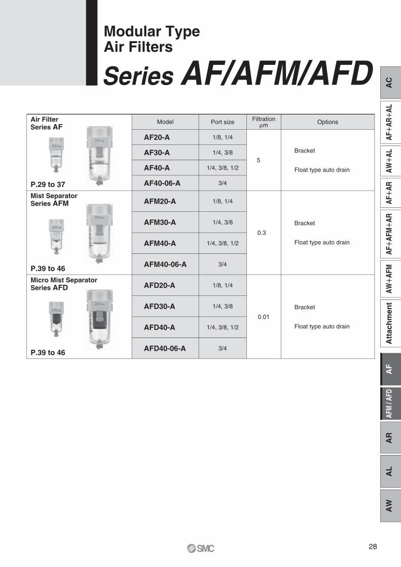
Air FilterSeries AF
Mist SeparatorSeries AFM
P.29 to 37
P.39 to 46
P.39 to 46
Micro Mist SeparatorSeries AFD
AFM20-A
AFM30-A
AFM40-A
AFM40-06-A
AFD20-A
AFD30-A
AFD40-A
AFD40-06-A
Options
Bracket
Float type auto drain
Bracket
Float type auto drain
Bracket
Float type auto drain
Port size
1/8, 1/4
1/4, 3/8
1/4, 3/8, 1/2
3/4
1/8, 1/4
1/4, 3/8
1/4, 3/8, 1/2
3/4
1/8, 1/4
1/4, 3/8
1/4, 3/8, 1/2
3/4
Filtrationμm
5
0.3
0.01
Model
AF20-A
AF30-A
AF40-A
AF40-06-A
Series AF/AFM/AFDModular TypeAir Filters
AC
AFAR
ALAW
ALAF
ARAF
AFM
ARAW
AFM
AF
AFM
/ AF
DA
RA
LA
WA
ttac
hm
ent
28

Made to Order(Refer to pages 36 and 37 for details.)
+
+
+
+
+
+
+
AF40-AAF20-A
AF A30q
03e
BDr tw
SymbolAir Filter Air Filter with Auto Drain
Note 1) Drain guide is NPT1/8 (applicable to the AF20-A) and NPT1/4 (applicable to the AF30-A to AF40-A). The auto drain port comes with ø3/8" One-touch fitting (applicable to the AF30-A to AF40-A).
Note 2) Drain guide is G1/8 (applicable to the AF20-A) and G1/4 (applicable to the AF30-A to AF40-A).Note 3) A bracket is not assembled and supplied loose at the time of shipment. Including 2 mounting screws.Note 4) When pressure is not applied, condensate which does not start the auto drain mechanism will be left in the bowl. Releasing the residual condensate before
ending operations for the day is recommended.Note 5) If the compressor is small (0.75 kW, discharge flow is less than 100 L/min[ANR]), air leakage from the drain cock may occur during start of operations. N.C. type is recommended.Note 6) Refer to Chemical data on page 32 for chemical resistance of the bowl.Note 7) A bowl guard is provided as standard equipment (polycarbonate).Note 8) Without a valve functionNote 9) For thread type: NPT.Note 10) �: For thread type: NPT onlyNote 11) The combination of float type auto drain: C and D is not available.Note 12) The combination of metal bowl: 2 and 8 is not available.
���
���
���
20 30 40Body sizeDescription
RcNPT
G
Symbol
—N Note 1)
F Note 2)
Thread typew
q
��———
—��——
—����
1/81/43/81/23/4
0102030406
Port sizee
��
��
��
—B Note 3)
Mounting
r
t
aWithout mounting optionWith bracket
��
��
��
—R
Flow directioneFlow direction: Left to rightFlow direction: Right to left
��—
���
���
—C Note 4)
D Note 5)
Float type auto drain
bWithout auto drainN.C. (Normally closed) Drain port is closed when pressure is not applied.N.O. (Normally open) Drain port is open when pressure is not applied.
���—��
����
— Note 7)
— Note 7)
����
— Note 7)
— Note 7)
—268C6C
Bowl Note 6)c
Polycarbonate bowlMetal bowlNylon bowlMetal bowl with level gaugeWith bowl guardWith bowl guard (Nylon bowl)
��——
�—��
�—��
—
J Note 8)
W Note 12)
Drain port Note 11)d
With drain cockDrain guide 1/8Drain guide 1/4Drain cock with barb fitting (for ø6 x ø4 nylon tube)
�� Note 10)
�� Note 10)
�� Note 10)
—Z Note 9)
Pressure unitfName plate and caution plate for bowl in imperial units: MPaName plate and caution plate for bowl in imperial units: psi, °F
21
L
21
L
Opt
ion
Sem
i-sta
ndar
d
a to f.
required, indicate in alphanumeric order.Example) AF30-03BD-R-A
How to Order
AF20-A to AF40-AAir Filter
29

N.C. N.O.
ModelSemi-standard specifications
Bowl material
Polycarbonatebowl
Metal bowl
Nylon bowl
Metal bowl with level gauge
AF40-06-AAF40-AAF30-A
C2SF-C-AAD27-C-AC2SF-J-A
—C2SF-CJ-AC2SF-6-A
C2SF-6C-AAD27-6-A
—AD27-6C-AC2SF-6J-A
—C2SF-6CJ-A
C2SF-2-AAD27-2-A
—C2SF-2J-A
————
——
C3SF-J-AC3SF-W-A
—C3SF-6-A
—AD37-6-AAD38-6-A
—C3SF-6J-AC3SF-6W-A
—C3SF-2-AAD37-2-AAD38-2-AC3SF-2J-AC3LF-8-AAD37-8-AAD38-8-AC3LF-8J-A
——
C4SF-J-AC4SF-W-A
—C4SF-6-A
—AD47-6-AAD48-6-A
—C4SF-6J-AC4SF-6W-A
—C4SF-2-AAD47-2-AAD48-2-AC4SF-2J-AC4LF-8-AAD47-8-AAD48-8-AC4LF-8J-A
AF20-A
Standard Specifications
Air–5 to 60°C (with no freezing)
1.5 MPa1.0 MPa
5 μm
Polycarbonate
8
Semi-standard (Steel)0.08
25
0.18 0.36 0.41
45
Standard (Polycarbonate)
ModelPort sizeFluidAmbient and fluid temperatureProof pressureMaximum operating pressureNominal filtration ratingDrain capacity [cm3]Bowl materialBowl guardWeight [kg]
AF20-A1/8, 1/4
AF30-A1/4, 3/8
AF40-A1/4, 3/8, 1/2
AF40-06-A3/4
Options/Part No.
AF22P-050ASAD27-A
—
AF32P-050ASAD37-AAD38-A
AD47-AAD48-A
AF42P-050AS AF42P-070ASN.C.N.O.
ModelOptional specifications
Bracket assembly Note 1)
Float type auto drain Note 2) Note 3)
AF20-A AF30-A AF40-A AF40-06-A
Semi-standard/Bowl Assembly Part No.
Note 1) Assembly of a bracket and 2 mounting screwsNote 2) Minimum operating pressure: N.O. type–0.1 MPa; N.C. type–0.1 MPa (AD27-A) and 0.15 MPa (AD37-A/47-A).
Please consult with SMC separately for psi and °F unit display specifications.Note 3) Please consult with SMC for details on drain piping to fit NPT or G port sizes.Note) Bowl assembly for the AF20-A to AF40-A models comes with a bowl O-ring.
Withbowlguard
Withbarbfitting
With drain guide
Note 3)
Float type auto drain
Note 2) Note 3)
Air Filter Series AF20-A to AF40-A
—�—————�—�————�———�——
————————�——————�———�—
——�—�—————�—�———�———�
———�———————�—————————
��——�—�——�——�————————
AC
AFAR
ALAW
ALAF
ARAF
AFM
ARAW
AFM
AF
AFM
/ AF
DA
RA
LA
WA
ttac
hm
ent
30

0.10
0.08
0.06
0.04
0.02
00 500 1000 1500
AF20-A Rc1/4
Flow rate L/min [ANR]
Pre
ssur
e dr
op [M
Pa]
0.10
0.08
0.06
0.04
0.02
00 20001000 3000 4000
AF30-A Rc3/8
Flow rate L/min [ANR]
Pre
ssur
e dr
op [M
Pa]
0.10
0.08
0.06
0.04
0.02
00 2000 4000 6000
AF40-A Rc1/2
Flow rate L/min [ANR]
Pre
ssur
e dr
op [M
Pa]
0.10
0.08
0.06
0.04
0.02
00
AF40-06-A Rc3/4
Flow rate L/min [ANR]
Pre
ssur
e dr
op [M
Pa]
2000 4000 6000
Flow-rate Characteristics (Representative values)
P1 =
0.1
MPa
P1 =
0.3
MPa
P1 =
0.5
MPa
P1 =
0.7
MPa
P1
= 0.
1 M
Pa
P1 =
0.3
MPa
P1 =
0.5
MPa
P1 =
0.7
MPa
P1
= 0.
1 M
Pa
P1 =
0.3
MPa
P1 =
0.5
MPa
P1 =
0.7
MPa
P1 =
0.1
MPa
P1 =
0.3
MPa
P1 =
0.5
MPa
P1 =
0.7
MPa
Series AF20-A to AF40-A
31

When the above factors are present, or there is some doubt, use a metal bowl for safety.
Specific Product Precautions
Maintenance
1. Replace the element every 2 years or when the pressure drop becomes 0.1 MPa, whichever comes first, to prevent damage to the element.
WarningWarning
Mounting/Adjustment
1. When the bowl is installed on the air filter, install them so that the lock button lines up to the groove of the front (or the back) of the body to avoid drop or damage of the bowl.
Caution
Lock button
Design/Selection
1. The standard bowl for the air filter, filter regulator, and lubricator, as well as the sight dome for the lubricator are made of polycarbonate. Do not use in an environ-ment where they are exposed to or come in contact with organic solvents, chemicals, cutting oil, synthetic oil, alkali, and thread lock solutions.
Acid
Alkaline
Inorganicsalts
Chlorine solvents
Aromaticseries
Ketone
Alcohol
Oil
Ester
Ether
Amino
Others
Chemical nameType Application examplesMaterial
Acid washing liquid for metals
Degreasing of metalsIndustrial saltsWater-solublecutting oil
Cleansing liquid for metalsPrinting inkDilution
CoatingsDry cleaning
Photographic filmDry cleaningTextile industries
AntifreezeAdhesives
Synthetic oilAnti-rust additives
Brake oil additives
Cutting oilBrake oil additivesRubber accelerator
Hydrochloric acidSulfuric acid, Phosphoric acidChromic acidSodium hydroxide (Caustic soda)PotashCalcium hydroxide (Slack lime)Ammonia waterCarbonate of sodaSodium sulfideSulfate of potashSulfate of sodaCarbon tetrachlorideChloroformEthylene chlorideMethylene chlorideBenzeneToluenePaint thinnerAcetoneMethyl ethyl ketoneCyclohexaneEthyl alcoholIPAMethyl alcohol
GasolineKerosene
Phthalic acid dimethylPhthalic acid diethylAcetic acidMethyl etherEthyl ether
Methyl amino
Thread-lock fluidSeawaterLeak tester
�
�
�
�
�
�
�
�
�
�
�
�
�
�
�
�
�
�
�
�
�
�
�
�
�: Essentially safe. �: Some effects may occur. �: Effects will occur.
—
—
—
Effects of atmosphere of organic solvents and chemicals, and where these elements are likely to adhere to the equipment.Chemical data for substances causing degradation (Reference)
Air Filter Series AF20-A to AF40-A
Be sure to read before handling. Refer to back cover for Safety Instructions, “Handling Precautions for SMC Products” (M-E03-3) and the Operation Manual for F.R.L. Precautions.
Polycar-bonate
Nylon
AC
AFAR
ALAW
ALAF
ARAF
AFM
ARAW
AFM
AF
AFM
/ AF
DA
RA
LA
WA
ttac
hm
ent
32
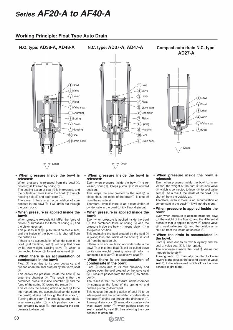
Bowl
Valve
Lever
Float
Valve seatValve seat
Chamber
Piston
Spring
Housing
Seal
Drain cock
q
r
e
w
t
i
u
y
o
!0
!1
Bowl
Valve
Lever
Float
Chamber
Piston
Spring
Housing
Seal
Drain cock
q
r
e
w
t
i
y
u
o
!0
!1
Bowl
Float
Lever
Valve
Valve seat
Knob
q
w
e
r
t
y
Working Principle: Float Type Auto Drain
Even when pressure inside the bowl q is re-leased, spring y keeps piston u in its upward position.This keeps the seal created by the seal !0 in place; thus, the inside of the bowl q is shut off from the outside air.Therefore, even if there is an accumulation of condensate in the bowl q, it will not drain out.
Even when pressure is applied inside the bowl q, the combined force of spring y and the pressure inside the bowl q keeps piston u in its upward position.This maintains the seal created by the seal !0 in place; thus, the inside of the bowl q is shut off from the outside air.If there is no accumulation of condensate in the bowl q at this time float w will be pulled down by its own weight, causing valve r, which is connected to lever e, to seal valve seat t.
Float w rises due to its own buoyancy and pushes open the seal created by the valve seat t. Pressure passes from the bowl q to cham-ber i.The result is that the pressure inside chamber i surpasses the force of the spring y and pushes piston u downward.This causes the sealing action of seal !0 to be interrupted and the accumulated condensate in the bowl q drains out through the drain cock !1.Turning drain cock !1 manually counterclock-wise lowers piston u, which pushes open the seal created by seal !00, thus allowing the con-densate to drain out.
When pressure is released from the bowl q, piston u is lowered by spring y.The sealing action of seal !0 is interrupted, and the outside air flows inside the bowl q through housing hole o and drain cock !1.Therefore, if there is an accumulation of con-densate in the bowl q, it will drain out through the drain cock.
When pressure exceeds 0.1 MPa, the force of piston u surpasses the force of spring y, and the piston goes up.This pushes seal !0 up so that it creates a seal, and the inside of the bowl q, is shut off from the outside air.If there is no accumulation of condensate in the bowl q at this time, float w will be pulled down by its own weight, causing valve r, which is connected to lever e, to seal valve seat t.
Float w rises due to its own buoyancy and pushes open the seal created by the valve seat t.This allows the pressure inside the bowl q to enter the chamber i. The result is that the combined pressure inside chamber i and the force of the spring y lowers the piston u.This causes the sealing action of seal !0 to be interrupted, and the accumulated condensate in the bowl q drains out through the drain cock !1.Turning drain cock !1 manually counterclock-wise lowers piston u, which pushes open the seal created by seal !0, thus allowing the con-densate to drain out.
N.C. type: AD37-A, AD47-AN.O. type: AD38-A, AD48-AAD27-A
Even when pressure inside the bowl q is re-leased, the weight of the float w causes valve r, which is connected to lever e, to seal valve seat t. As a result, the inside of the bowl q is shut off from the outside air.Therefore, even if there is an accumulation of condensate in the bowl q, it will not drain out.
Even when pressure is applied inside the bowl q, the weight of the float w and the differential pressure that is applied to valve r cause valve r to seal valve seat t, and the outside air is shut off from the inside of the bowl q.
Float w rises due to its own buoyancy and the seal at valve seat t is interrupted.The condensate inside the bowl q drains out through the knob y.Turning knob y manually counterclockwise lowers it and causes the sealing action of valve seat t to be interrupted, which allows the con-densate to drain out.
DrainDrain
Drain
Series AF20-A to AF40-A
33

Construction
AF20-A AF30-A to AF40-06-A
OUTOUT
ININ
Drain
Drain
Component PartsNo. Description
Body
Material
Aluminium die-cast White
Colour
1
No. Description
Filter element
Baffle
Bowl O-ring
Bowl assembly Note)
Material
Non-woven fabric
PBT
NBR
Polycarbonate
Part no.
AF20-A AF30-A AF40-A AF40-06-AAF20P-060S
AF22P-040S
C2SFP-260S
C2SF-A
AF30P-060S
AF32P-040S
C32FP-260S
C3SF-A
AF40P-060S
AF42P-040S
C42FP-260S
C4SF-A
2
3
4
5
Replacement Parts
Note) Bowl O-ring is included. Please contact SMC regarding the bowl assembly supply for psi and °F unit specifications.
q
r
w
e
t
q
r
w
e
t
Air Filter Series AF20-A to AF40-A
AC
AFAR
ALAW
ALAF
ARAF
AFM
ARAW
AFM
AF
AFM
/ AF
DA
RA
LA
WA
ttac
hm
ent
34

1/8
B
B B B
1/4
B
1/4
B
M5 x 0.8
B
1/8
B
Thread type/Rc, G: ø10 One-touch fittingThread type/NPT: ø3/8" One-touch fitting
B
1/4
B
Barb fitting Applicable tubing: T0604
B
R
S
Drain
OUTIN
TN
B
Cle
aran
ce fo
r m
aint
enan
ceGA
C
U
V
MD
JBracket(Option)
Q
2 x P (Port size)
S
R
Drain
TN
BC
Clea
ranc
e fo
r m
aint
enan
ceG
A
IN OUT
UJ M
D
VQ
Bracket(Option)
E
2 x P (Port size)
N.C.: GrayN.O.: Black
Width acrossflats 14 Width across
flats 14
Width acrossflats 17
Width acrossflats 17
Width acrossflats 17
AF30-A to AF40-06-A
ModelSemi-standard specifications
With barb fitting With drain guideB—
123.6155.6157.6
B 91.4121.9153.9155.9
Metal bowlB
87.4117.6149.6151.6
Metal bowl with drain guideB
93.9122.1154.1156.1
AF20-AAF30-AAF40-AAF40-06-A
Metal bowl with level gaugeB—
137.6169.6171.6
Metal bowl with level gauge, with drain guideB—
142.1174.1176.1
Drain cock with barb fittingWith drain guideOptional/Semi-standard specifications
Dimensions
Applicable model AF30-A to AF40-06-A
With drain guideWith auto drain (N.C.)Optional/Semi-standard specifications
Dimensions
Applicable model AF20-A AF30-A to AF40-06-A
With auto drain (N.O./N.C.)
Dimensions
AF20-A
ModelStandard specifications
Optional specifications
P1/8, 1/41/4, 3/8
1/4, 3/8, 1/23/4
A40537075
B 87.6115.1147.1149.1
C 9.814 18 20
D20 26.735.535.5
E—
30 38.438.4
G J20 26.735.535.5
M30415050
N27405454
Q22232625
R 5.4 6.5 8.5 8.5
S 8.48
10.510.5
T40537070
U2.32.32.32.3
V28303534
B104.9156.8186.9188.9
AF20-AAF30-AAF40-AAF40-06-A
Bracket mount With auto drain
25354040
Metal bowl with drain guideMetal bowl
Metal bowl with drain guideMetal bowl
with level gaugeMetal bowl with level gauge,
with drain guideMetal bowl
Series AF20-A to AF40-A
35

Note 1) Drain guide is NPT1/8 (applicable to the AF20-A) and NPT1/4 (applicable to the AF30-A to AF40-A).Note 2) Drain guide is G1/8 (applicable to the AF20-A) and G1/4 (applicable to the AF30-A to AF40-A).Note 3) A bracket is not assembled and supplied loose at the time of shipment. Including 2 mounting screws.Note 4) Refer to Chemical data on page 32 for chemical resistance of the bowl.Note 5) Without a valve functionNote 6) The combination of metal bowl: 2 is not available.Note 7) For thread type: NPT.Note 8) �: For thread type: NPT only
Note) Please consult with SMC for dimensions.
20 30 40Body sizeDescription
RcNPT
G
Symbol
—N Note 1)
F Note 2)
Thread typew
q
1/81/43/81/23/4
0102030406
Port sizee
—B Note 3)
Option (Mounting)r
t
Sem
i-sta
ndar
d
Without mounting optionWith bracket
—R
Flow directioncFlow direction: Left to rightFlow direction: Right to left
—26C6C
Bowl Note 4)a
Polycarbonate bowlMetal bowlNylon bowlWith bowl guardWith bowl guard (Nylon bowl)
—
J Note 5)
W Note 6)
Drain portb
With drain cockDrain guide 1/8Drain guide 1/4Drain cock with barb fitting (for ø6 x ø4 nylon tube)
—Z
Note 7)Pressure unitd
Name plate and caution plate for bowl in imperial units: MPaName plate and caution plate for bowl in imperial units: psi, °F
q Long BowlDrain capacity is greater than that of standard models.
a to d.
Example) AF30-03B-2R-A-X64
q
30AF X64w te
03r
Long bowl
Applicable Model/Drain Capacity
Port size
Drain capacity [cm3]
Model AF30-A AF40-A AF40-06-AAF20-A1/8, 1/4
19
1/4, 3/8
43
1/4, 3/8, 1/2 3/4
88
Air Filter/AF20-A to AF40-A
Made to OrderPlease contact SMC for detailed dimensions, specifications, and lead times.
A
+
+
+
+
+
+
���
��———
��
�����
��——
��
�� Note 8)
���
—��——
��
���——
�—��
��
�� Note 8)
���
—����
��
���——
�—��
��
�� Note 8)
AC
AFAR
ALAW
ALAF
ARAF
AFM
ARAW
AFM
AF
AFM
/ AF
DA
RA
LA
WA
ttac
hm
ent
36

w With Element Service IndicatorClogging status of elements can be checked visually.
Applicable Model
Port size
Model
1/8, 1/4 1/4, 3/8 1/4, 3/8, 1/2
a to f.
AF20-A AF40-A AF40-06-AAF30-A3/4
Air Filter/AF20-A to AF40-A
Made to Order
.
�
20 30 40
—NF
w
q
1/81/43/81/23/4
0102030406
e
r
t
Mountinga—
B
—R
e
—CD
b
—
J
W
d
—Z
f
—268C6C
c
q
30AF X2141w te
03r
With element service indicator
A
+
+
+
+
+
+
+
���
��———
��
��—
���—��
��——
��
��
���
—��——
��
���
����
—
—
�—��
��
��
���
—����
��
���
����
—
—
�—��
��
��
37

AC
AFAR
ALAW
ALAF
ARAF
AFM
ARAW
AFM
AF
AFM
/ AF
DA
RA
LA
WA
ttac
hm
ent
38

Made to Order(Refer to pages 45 and 46 for details.)
+
+
+
+
+
+
+
Note 1) Drain guide is NPT1/8 (applicable to the AFM20-A, AFD20-A) and NPT1/4 (applicable to the AFM30-A/40-A, AFD30-A/40-A). The auto drain port comes with ø3/8" One-touch fitting (applicable to the AFM30-A/40-A, AFD30-A/40-A).Note 2) Drain guide is G1/8 (applicable to the AFM20-A, AFD20-A) and G1/4 (applicable to the AFM30-A/40-A, AFD30-A/40-A).Note 3) A bracket is not assembled and supplied loose at the time of shipment. Including 2 mounting screwsNote 4) When pressure is not applied, condensate which does not start the auto drain mechanism will be left in the bowl. Releasing the residual condensate before
ending operations for the day is recommended.Note 5) If the compressor is small (0.75 kW, discharge flow is less than 100 L/min[ANR]), air leakage from the drain cock may occur during start of operations. N.C. type is recommended.Note 6) Refer to Chemical data on page 42 for chemical resistance of the bowl.Note 7) A bowl guard is provided as standard equipment (polycarbonate).Note 8) Without a valve functionNote 9) For thread type: NPT.Note 10) �: For thread type: NPT onlyNote 11) The combination of float type auto drain: C and D is not available.Note 12) The combination of metal bowl: 2 and 8 is not available.
Mist Separator
AFM20-A to AFM40-AMicro Mist Separator
AFD20-A to AFD40-Aμμ
q e r tw
Mist Separator
Micro Mist Separator
��
��
��
��———
—��——
—����
Description
RcNPT
G
Symbol
— Note 1)
Note 2)
—B Note 3)
Thread type
Mounting
�w
1/81/43/81/23/4
Port size�e
�r
Opt
ion
aWithout mounting optionWith bracket
��—
���
���
—C Note 4)
Note 5)
Float typeauto drain
Without auto drainN.C. (Normally closed) Drain port is closed when pressure is not applied.N.O. (Normally open) Drain port is open when pressure is not applied.
���—��
����
— Note 7)
— Note 7)
����
— Note 7)
— Note 7)
—
8C
Bowl Note 6)c
Polycarbonate bowlMetal bowlNylon bowlMetal bowl with level gaugeWith bowl guardWith bowl guard (Nylon bowl)
��——
�—��
�—��
��
��
��
�� Note 10)
�� Note 10)
�� Note 10)
—
J Note 8)
W Note 12)
Drain port Note 11)d
With drain cockDrain guide 1/8Drain guide 1/4Drain cock with barb fitting (for ø6 x ø4 nylon tube)
—R
Flow direction
�t
eFlow direction: Left to rightFlow direction: Right to left
—Z Note 9)
Pressure unitName plate and caution plate for bowl in imperial units: MPaName plate and caution plate for bowl in imperial units: psi, °F
Sem
i-sta
ndar
d
���
���
���
Body size
�q
21
L
21
L
How to Order
a to .
specification is required, indicate in alphanumeric order.Example) AFM30-03BD-R-A
39

Note 1) Assembly of a bracket and 2 mounting screwsNote 2) Minimum operating pressure: N.O. type–0.1 MPa; N.C. type–0.1 MPa (AD27-A) and 0.15 MPa (AD37-A/47-A).
Please consult with SMC separately for psi and °F unit display specifications.Note 3) Please consult with SMC for details on drain piping to fit NPT or G port sizes.Note 4) The bowl assembly includes the bowl O-ring.
ModelSemi-standard specifications
Bowlmaterial
Polycarbonatebowl
Metal bowl
Nylon bowl
Metal bowlwith level gauge
AFM40-06-AAFD40-06-A
AFM40-AAFD40-A
AFM30-AAFD30-A
C2SF-C-AAD27-C-AC2SF-J-A
—C2SF-CJ-AC2SF-6-A
C2SF-6C-AAD27-6-A
—AD27-6C-AC2SF-6J-A
—C2SF-6CJ-A
C2SF-2-AAD27-2-A
—C2SF-2J-A
————
——
C3SF-J-AC3SF-W-A
—C3SF-6-A
—AD37-6-AAD38-6-A
—C3SF-6J-AC3SF-6W-A
—C3SF-2-AAD37-2-AAD38-2-AC3SF-2J-AC3LF-8-AAD37-8-AAD38-8-AC3LF-8J-A
——
C4SF-J-AC4SF-W-A
—C4SF-6-A
—AD47-6-AAD48-6-A
—C4SF-6J-AC4SF-6W-A
—C4SF-2-AAD47-2-AAD48-2-AC4SF-2J-AC4LF-8-AAD47-8-AAD48-8-AC4LF-8J-A
AFM20-AAFD20-A
Note 1) Conditions: Inlet pressure: 0.7 MPa; The rated flow varies depending on the inlet pressure. Keep the air flow within the rated flow to prevent an outflow of lubricant to the outlet side.
Note 2) When the compressor oil mist discharge concentration is 30 mg/m3 (ANR).Note 3) Bowl O-ring and other O-rings are slightly lubricated.
Standard Specifications
Options/Part No.
Model
Port sizeFluidAmbient and fluid temperatureProof pressureMaximum operating pressureMinimum operating pressure
Nominal filtration rating
Outlet side oil mistconcentration
Rated flow [L/min (ANR)] Note 1)
Drain capacity [cm3]Bowl materialBowl guardWeight [kg]
AFM20-A to AFM40-06-AAFD20-A to AFD40-06-AAFM20-A to AFM40-06-AAFD20-A to AFD40-06-AAFM20-A to AFM40-06-AAFD20-A to AFD40-06-A
1/8, 1/4 1/4, 3/8 1/4, 3/8, 1/2
AFM40-06-AAFD40-06-A
AFM40-AAFD40-A
AFM30-AAFD30-A
AFM20-AAFD20-A
3/4Air
– 5 to 60°C (with no freezing)1.5 MPa1.0 MPa0.05 MPa
0.3 μm (99.9% filtered particle size)0.01 μm (99.9% filtered particle size)
MAX 1.0 mg/m3 (ANR) (≈ 0.8 ppm) Note 2) Note 3)
MAX 0.1 mg/m3 (ANR) (Before saturated with oil 0.01 mg/m3 (ANR) or less ≈ 0.008 ppm) Note 2) Note 3)
Polycarbonate
2001208
Semi-standard (Steel)0.09
45024025
0.19Standard (Polycarbonate)
0.38 0.43
1100 60045
AFM40-06-AAFD40-06-A
AFM40-AAFD40-A
AFM30-AAFD30-A
AFM20-AAFD20-A
ModelOptional specifications
Bracket assembly Note 1)
Float type auto drain Note 2) Note 3)
AF42P-070ASAF42P-050ASAF32P-050ASAD37-AAD38-A
AF22P-050ASAD27-A
—AD47-AAD48-A
N.C. N.O.
Semi-standard/Bowl Assembly Part No.
—�—————�—�————�———�——
————————�——————�———�—
——�—�—————�—�———�———�
———�———————�—————————
��——�—�——�——�————————
Float typeauto drain
Note 2) Note 3)
N.C. N.O.
Withbowlguard
Withbarbfitting
Withdrainguide
Note 3)
Mist Separator Series AFM20-A to AFM40-AMicro Mist Separator Series AFD20-A to AFD40-A
AC
AFAR
ALAW
ALAF
ARAF
AFM
ARAW
AFM
AF
AFM
/ AF
DA
RA
LA
WA
ttac
hm
ent
40

AFM20-A
50 100 150 200
0.04
0.03
0.02
0.01
00
Flow rate L/min [ANR]
Pre
ssur
e dr
op [M
Pa]
P1 = 0.3 MPa
P1 = 0.5 MPa
P1 = 0.7 MPa
P1 = 0.3 MPa
P1 = 0.5 MPa
P1 = 0.7 MPa
AFD20-A
50 100
0.04
0.03
0.02
0.01
00
Flow rate L/min [ANR]P
ress
ure
drop
[MP
a]
P1 = 0.3 MPa
P1 = 0.5 MPa
P1 = 0.7 MPa
P1 = 0.3 MPa
P1 = 0.5 MPa
P1 = 0.7 MPa
100 200 300 500400 600
0.04
0.03
0.02
0.01
00
AFM30-A
Flow rate L/min [ANR]
Pre
ssur
e dr
op [M
Pa]
P1 = 0.3 MPa
P1 = 0.5 MPa
P1 = 0.7 MPa
P1 = 0.3 MPa
P1 = 0.5 MPa
P1 = 0.7 MPa
AFD30-A
50 100 150 200
0.04
0.03
0.02
0.01
00
Flow rate L/min [ANR]
Pre
ssur
e dr
op [M
Pa]
P1 = 0.3 MPa
P1 = 0.5 MPa
P1 = 0.7 MPa
P1 = 0.3 MPa
P1 = 0.5 MPa
P1 = 0.7 MPa
200 800 1000400 600
0.04
0.03
0.02
0.01
00
AFM40-A
Flow rate L/min [ANR]
Pre
ssur
e dr
op [M
Pa] P1 = 0.3 M
Pa
P1 = 0.5 MPa
P1 = 0.7 MPa
P1 = 0.3 MPaP1 = 0.5 MPa
P1 = 0.7 MPa
100 200 300 500400 600
0.04
0.03
0.02
0.01
00
AFD40-A
Flow rate L/min [ANR]
Pre
ssur
e dr
op [M
Pa]
P1 = 0.3 MPa
P1 = 0.5 MPa
P1 = 0.7 MPa
P1 = 0.3 MPaP1 = 0.5 MPa
P1 = 0.7 MPa
Flow-rate Characteristics (Representative values)When saturated with oilInitial state
Series AFM20-A to AFM40-ASeries AFD20-A to AFD40-A
41

Air Supply
1. Install an air filter (Series AF) as a pre-filter on the inlet side of the mist separator to prevent premature clogging.
2. Install a mist separator (Series AFM) as a pre-filter on the inlet side of the micro mist separator to prevent premature clogging.
3. Do not install on the inlet side of the dryer as this can cause premature clogging of the element.
Caution
Maintenance
1. Replace the element every 2 years or when the pressure drop becomes 0.1 MPa, whichever comes first, to prevent damage to the element.
Warning
Design
1. Design the system so that the mist separator is installed in a pulsation-free location. The difference between internal and external pressure inside the element should be kept within 0.1 MPa, as exceeding this value could cause damage.
Caution
Caution
Selection
1. Do not allow air flow that exceeds the rated flow. If the air flow is allowed outside the range of the rated flow even momen-tarily, drainage and lubricant may splash at the outlet side or cause damage to the component.
2. Do not use in a low pressure application (such as a blower). F.R.L. unit has its own minimum operating pressure depending on the equipment and is designed specifically to function with compressed air. If used below the minimum operating pres-sure, a loss of performance and malfunction can occur. Please contact SMC if an application under such conditions cannot be avoided.
Caution
Specific Product Precautions
Mounting/Adjustment
1. When the bowl is installed on the mist separator, or micro mist separa-tor, install them so that the lock but-ton lines up to the groove of the front (or the back) of the body to avoid drop or damage of the bowl.
WarningDesign/Selection
1. The standard bowl for the air filter, filter regulator, and lubricator, as well as the sight dome for the lubricator are made of polycarbonate. Do not use in an environment where they are exposed to or come in contact with organic solvents, chemicals, cutting oil, synthetic oil, alkali, and thread lock solutions.
Acid
Alkaline
Inorganicsalts
Chlorine solvents
Aromaticseries
Ketone
Alcohol
Oil
Ester
Ether
Amino
Others
Chemical nameType Application examplesMaterial
Acid washing liquid for metals
Degreasing of metalsIndustrial salts Water-soluble cutting oil
Cleansing liquid for metalsPrinting ink Dilution
CoatingsDry cleaning
Photographic filmDry cleaningTextile industries
AntifreezeAdhesives
Synthetic oilAnti-rust additives
Brake oil additives
Cutting oilBrake oil additives Rubber accelerator
Hydrochloric acidSulfuric acid, Phosphoric acidChromic acidSodium hydroxide (Caustic soda)PotashCalcium hydroxide (Slack lime)Ammonia waterCarbonate of sodaSodium sulfideSulfate of potashSulfate of sodaCarbon tetrachlorideChloroformEthylene chlorideMethylene chlorideBenzeneToluenePaint thinnerAcetoneMethyl ethyl ketoneCyclohexaneEthyl alcoholIPAMethyl alcohol
GasolineKerosene
Phthalic acid dimethylPhthalic acid diethylAcetic acidMethyl etherEthyl ether
Methyl amino
Thread-lock fluidSeawaterLeak tester
�
�
�
�
�
�
�
�
�
�
�
�
�: Essentially safe. �: Some effects may occur. �: Effects will occur.
—
—
—
Effects of atmosphere of organic solvents and chemicals, and where these elements are likely to adhere to the equipment.Chemical data for substances causing degradation (Reference)
Lock button
Mist Separator Series AFM20-A to AFM40-AMicro Mist Separator Series AFD20-A to AFD40-A
Be sure to read before handling. Refer to back cover for Safety Instructions, “Handling Precautions for SMC Products” (M-E03-3) and the Operation Manual for F.R.L. Precautions.
When the above factors are present, or there is some doubt, use a metal bowl for safety.
Polycar-bonate
Nylon
�
�
�
�
�
�
�
�
�
�
�
�
AC
AFAR
ALAW
ALAF
ARAF
AFM
ARAW
AFM
AF
AFM
/ AF
DA
RA
LA
WA
ttac
hm
ent
42

q
e
w
r
OUTIN
q
e
w
r
OUTIN
M5 x 0.8
Float type auto drain (N.C.)
Float type auto drain
Thread type/Rc,G: ø10 One-touch fittingThread type/NPT: ø3/8" One-touch fitting
Thread type/Rc,G: ø10 One-touch fittingThread type/NPT: ø3/8" One-touch fitting
N.C. N.O.
Drain
Drain
Component PartsNo. Description
Body
Material
Aluminium die-cast
Model
AFM20-A to AFM40-06-AAFD20-A to AFD40-06-A
White
Colour
1
No. Description
Element assembly
Bowl seal
Bowl assembly Note)
Material
—
—
NBR
Polycarbonate
Part no.
AFM20-AAFD20-A
AFM30-AAFD30-A
AFM40-AAFD40-A
AFM40-06-AAFD40-06-A
AFM20P-060AS
AFD20P-060AS
C2SFP-260S
C2SF-A
AFM20 to 40
AFD20 to 40
AFM30P-060AS
AFD30P-060AS
C32FP-260S
C3SF-A
AFM40P-060AS
AFD40P-060AS
C42FP-260S
C4SF-A
2
3
4
Replacement Parts
Note) Bowl seal is included. Please contact SMC regarding the bowl assembly supply for psi and °F unit specifications.
AFM30-A to AFM40-06-AAFD30-A to AFD40-06-A
AFM20-AAFD20-A
Construction
Series AFM20-A to AFM40-ASeries AFD20-A to AFD40-A
43

1/8
B
B B B
1/4
B
1/4
B
M5 x 0.8
B
1/8
B
B
Thread type/Rc,G: ø10 One-touch fittingThread type/NPT: ø3/8" One-touch fitting
Barb fitting Applicable tubing: T0604
1/4
B B
R
S
Drain
OUTIN
TN
BC
Cle
aran
ce fo
rm
aint
enan
ceGA
U
V
MD
JBracket(Option)
Q
2 x P (Port size)
S R
Drain
TN
BC
Cle
aran
ce fo
rm
aint
enan
ceG
A
IN OUT
UJ M
D
VQ
Bracket(Option)
E
2 x P (Port size)
N.O.: BlackN.C.: Grey
Width acrossflats 14
Width acrossflats 14
Width acrossflats 17
Width acrossflats 17
Width acrossflats 17
AFM30-A to AFM40-06-AAFD30-A to AFD40-06-A
ModelSemi-standard specifications
With barb fitting With drain guide
B—
123.6155.6157.6
B 91.4121.9153.9155.9
Metal bowl
B 87.4117.6149.6151.6
Metal bowl with drain guide
B 93.9122.1154.1156.1
Metal bowl with level gauge
B—
137.6169.6171.6
Metal bowl with level gauge, with drain guide
B—
142.1174.1176.1
AFM20-A/AFD20-AAFM30-A/AFD30-AAFM40-A/AFD40-AAFM40-06-A/AFD40-06-A
Drain cock with barb fittingWith drain guideOptional/Semi-standard specifications
Dimensions
Applicable model AFM30-A to AFM40-06-A/AFD30-A to AFD40-06-A
With drain guideWith auto drain (N.C.)Optional/Semi-standard specifications
Dimensions
Applicable model AFM20-A/AFD20-A AFM30-A to AFM40-06-A/AFD30-A to AFD40-06-A
With auto drain (N.O./N.C.)
AFM20-AAFD20-A
ModelStandard specifications
Optional specifications
P1/8, 1/41/4, 3/8
1/4, 3/8, 1/23/4
A40537075
B 87.6115.1147.1149.1
C 9.814 18 20
D20 26.735.535.5
E—
30 38.438.4
G J20 26.735.535.5
M N27405454
Q22232625
R5.46.58.58.5
S 8.48
10.510.5
T40537070
U2.32.32.32.3
V28303534
B104.9156.8186.9188.9
AFM20-A/AFD20-AAFM30-A/AFD30-AAFM40-A/AFD40-AAFM40-06-A/AFD40-06-A
Bracket mount With auto drain
30415050
40507575
Dimensions
Metal bowl with drain guideMetal bowl
Metal bowl with drain guideMetal bowl
with level gaugeMetal bowl with level gauge,
with drain guideMetal bowl
Mist Separator Series AFM20-A to AFM40-AMicro Mist Separator Series AFD20-A to AFD40-A
AC
AFAR
ALAW
ALAF
ARAF
AFM
ARAW
AFM
AF
AFM
/ AF
DA
RA
LA
WA
ttac
hm
ent
44

Mist Separator/AFM20-A to AFM40-AMicro Mist Separator/AFD20-A to AFD40-AMade to OrderPlease contact SMC for detailed dimensions, specifications, and lead times.
Note 1) Drain guide is NPT1/8 (applicable to the AFM20-A, AFD20-A) and NPT1/4 (applicable to the AFM30-A/40-A, AFD30-A/40-A).Note 2) Drain guide is G1/8 (applicable to the AFM20-A, AFD20-A) and G1/4 (applicable to the AFM30-A/40-A, AFD30-A/40-A).Note 3) A bracket is not assembled and supplied loose at the time of shipment. Including 2 mounting screws.Note 4) Refer to Chemical data on page 42 for chemical resistance of the bowl.Note 5) Without a valve functionNote 6) The combination of metal bowl: 2 is not available.Note 7) For thread type: NPT.Note 8) �: For thread type: NPT only
20 30 40Body sizeDescription
RcNPT
G
Symbol
—N Note 1)
F Note 2)
Thread typew
q
1/81/43/81/23/4
0102030406
Port sizee
—B Note 3)
Option (Mounting)r
t
Sem
i-sta
ndar
d
Without mounting optionWith bracket
—R
Flow directioncFlow direction: Left to rightFlow direction: Right to left
—26C6C
Bowl Note 4)a
Polycarbonate bowlMetal bowlNylon bowlWith bowl guardWith bowl guard (Nylon bowl)
—
J Note 5)
W Note 6)
Drain portb
With drain cockDrain guide 1/8Drain guide 1/4Drain cock with barb fitting (for ø6 x ø4 nylon tube)
—Z Note 7)
Pressure unitdName plate and caution plate for bowl in imperial units: MPaName plate and caution plate for bowl in imperial units: psi, °F
q Long BowlDrain capacity is greater than that of standard models.
a to d.
Example) AFM30-03B-2R-A-X64
q
30AFD X64w te
03
30AFM X6403
r Long bowl
Applicable Model/Drain Capacity
Port size
Drain capacity (cm3)
Model AFM20-A, AFD20-A AFM40-A, AFD40-A AFM40-06-A, AFD40-06-A1/8, 1/4
19
AFM30-A, AFD30-A1/4, 3/8
43
1/4, 3/8, 1/2 3/4
88
Note) Please consult with SMC for dimensions.
A
A
+
+
+
+
+
+
���
��———
��
�����
��——
��
�� Note 8)
���
—��——
��
���——
�—��
��
�� Note 8)
���
—����
��
���——
�—��
��
�� Note 8)
45

w With Element Service IndicatorClogging status of elements can be checked visually.
q
30AFD X2141w te
03
30AFM X214103
r With element service indicator
Applicable Model
Port size
Model AFM40-A, AFD40-A AFM40-06-A, AFD40-06-AAFM20-A, AFD20-A1/8, 1/4
AFM30-A, AFD30-A1/4, 3/8 1/4, 3/8, 1/2 3/4
Note 1) Drain guide is NPT1/8 (applicable to the AFM20-A, AFD20-A) and NPT1/4 (applicable to the AFM30-A/40-A, AFD30-A/40-A).The auto drain port comes with ø3/8" One-touch fitting (applicable to the AFM30-A/40-A, AFD30-A/40-A).
Note 2) Drain guide is G1/8 (applicable to the AFM20-A, AFD20-A) and G1/4 (applicable to the AFM30-A/40-A, AFD30-A/40-A).
Note 3) A bracket is not assembled and supplied loose at the time of shipment. Including 2 mounting screws
Note 4) When pressure is not applied, condensate which does not start the auto drain mechanism will be left in the bowl. Releasing the residual condensate before ending operations for the day is recommended.
Note 5) If the compressor is small (0.75 kW, discharge flow is less than 100 L/min[ANR]), air leakage from the drain cock may occur during start of operations. N.C. type is recommended.
Note 6) Refer to Chemical data on page 42 for chemical resistance of the bowl.Note 7) A bowl guard is provided as standard equipment (polycarbonate).Note 8) Without a valve functionNote 9) For thread type: NPT.Note 10) �: For thread type: NPT onlyNote 11) The combination of float type auto drain: C and D is not available.Note 12) The combination of metal bowl: 2 and 8 is not available.
DescriptionSymbol
1/81/43/81/23/4
0102030406
Port size�e
�r
Opt
ion
—B Note 3)Mountinga Without mounting option
With bracket
—C Note 4)
D Note 5)
Float typeauto drain
bWithout auto drainN.C. (Normally closed) Drain port is closed when pressure is not applied.N.O. (Normally open) Drain port is open when pressure is not applied.
—
J Note 8)
W Note 12)
Drain port Note 11)d
With drain cockDrain guide 1/8Drain guide 1/4Drain cock with barb fitting (for ø6 x ø4 nylon tube)
�t
—RFlow directione Flow direction: Left to right
Flow direction: Right to left
—Z Note 9)
Pressure unitf Name plate and caution plate for bowl in imperial units: MPaName plate and caution plate for bowl in imperial units: psi, °F
Sem
i-sta
ndar
d
RcNPT
G
—N Note 1)
F Note 2)
Thread type�w
20 30 40Body size
�q
• Option/Semi-standard: Select one each for a to f.• Option/Semi-standard symbol: When more than one specification is
required, indicate in alphanumeric order.Example) AFM30-03BD-R-A-X2141
A
A
—268C6C
Bowl Note 6)c
Polycarbonate bowlMetal bowlNylon bowlMetal bowl with level gaugeWith bowl guardWith bowl guard (Nylon bowl)
+
+
+
+
+
+
+
���
��———
��
��—
���—��
��——
��
�� Note 10)
���
—��——
��
���
����
— Note 7)
— Note 7)
�—��
��
�� Note 10)
���
—����
��
���
����
— Note 7)
— Note 7)
�—��
��
�� Note 10)
A special body type is required to mount the element service indicator. It cannot be mounted on a standard body.
Mist Separator/AFM20-A to AFM40-AMicro Mist Separator/AFD20-A to AFD40-AMade to OrderPlease contact SMC for detailed dimensions, specifications, and lead times.
AC
AF
AR
ALAW
AL
AF
ARAF
AF
M
ARAW
AF
MA
FAF
M /
AFD
AR
AL
AW
Att
ach
men
t
46

47

RegulatorSeries AR
P.49 to 55
Options
Bracket
Round type pressure gauge
∗ Not interchangeable with existing AR series
With set nut (for panel mount)∗
Port size
1/8, 1/4
1/4, 3/8
1/4, 3/8, 1/2
3/4
Model
AR20-A
AR25-A
AR30-A
AR40-A
AR40-06-A
Series ARModular TypeRegulators
AC
AFAR
ALAW
ALAF
ARAF
AFM
ARAW
AFM
AF
AFM
/ AF
DA
RA
LA
WA
ttac
hm
ent
48

+
+
+
+
+
+
+
AR30-AAR20-A
AR A30q
03e
BGr tw
SymbolRegulator
Note 1) Option B, G, H, M are not assembled and supplied loose at the time of shipment.Note 2) Assembly of a bracket and set nutsNote 3) Only for the AR20-A to 40-ANote 4) When the pressure gauge is attached, a 1.0 MPa pressure gauge will be fitted for standard (0.7 MPa) type. 0.4 MPa pressure gauge for 0.2 MPa type.Note 5) Pressure can be set higher than the specification pressure in some cases, but use pressure within the specification range.Note 6) For thread type: NPT
Cannot be used with M: Round pressure gauge (with colour zone). Available by request for special.Note 7) �: For thread type: NPT only
���
25Body sizeDescription
RcNPT
G
Symbol
—NF
Thread type�w
�q
—��——
1/81/43/81/23/4
0102030406
Port size�e
—B Note 2)
HMounting
�r
�t
Sem
i-sta
ndar
d
aWithout mounting optionWith bracketWith set nut (for panel mount) Note 3)
��
—R
Flow directioneFlow direction: Left to rightFlow direction: Right to left
���
���
—GM
bWithout pressure gaugeRound type pressure gauge (with limit indicator)Round type pressure gauge (with colour zone)
—1
c0.05 to 0.7 MPa setting0.02 to 0.2 MPa setting
���
20
��———
���
���
���
���
��
��
��
��
��
��
���
40
—����
��
���
���
30
—��——
��
��
—N
Exhaustmechanism
dRelieving typeNon-relieving type
��
��
��
���
—Y
KnobfDownwardUpward
+�
� Note 7)
��
�� Note 7)
��
�� Note 7)
��
�� Note 7)
—Z Note 6)
Pressure unitgName plate and pressure gauge in imperial units: MPaName plate and pressure gauge in imperial units: psi
21
How to Order
Pressuregauge Note 4)
Setpressure Note 5)
Made to Order(Refer to page 55 for details.)
a to g. Option/Semi-standard symbol: When more than one specification is required, indicate in alphanumeric order.
Example) AR30-03BG-1N-A
Opt
ion N
ote
1)
AR20-A to AR40-ARegulator
49

Standard Specifications
1/8Air
– 5 to 60°C (with no freezing)1.5 MPa1.0 MPa
0.05 to 0.7 MPaRelieving type
ModelPort sizePressure gauge port sizeFluidAmbient and fluid temperatureProof pressureMaximum operating pressureSet pressure rangeConstructionWeight [kg]
AR20-A1/8, 1/4
0.17
AR25-A1/4, 3/8
0.19
AR30-A1/4, 3/8
0.34 0.58 0.60
AR40-A1/4, 3/8, 1/2
AR40-06-A3/4
Options/Part No.
AR22P-270ASAR22P-260S
G36-10-�01G36-4-�01G36-10-�01-LG36-4-�01-L
G46-10-�01G46-4-�01G46-10-�01-LG46-4-�01-L
Standard0.02 to 0.2 MPa setting
Standard0.02 to 0.2 MPa setting
ModelOptional specifications
Bracket assembly Note 1)
Set nut
Pressuregauge
AR20-AAR27P-270ASAR22P-260S
AR25-AAR32P-270ASAR32P-260S
AR30-AAR42P-270ASAR42P-260S
AR40-AAR42P-270ASAR42P-260S
AR40-06-A
Note 1) Assembly of a bracket and set nutsNote 2) � in part numbers for a round pressure gauge indicates a type of connection thread. No indication is necessary for R; however, indicate N for NPT.
Please contact SMC regarding the connection thread NPT and pressure gauge supply for psi unit specifications.
Roundtype
Round type (with colour zone)
Specific Product Precautions
Selection
1. Although exhaust of the residual pressure to the inlet side is possible when eliminating the inlet pressure, exhaust is not possible when the set pressure is 0.15 MPa or less. Use the regulator with backflow function.
Warning
Maintenance
1. When using the regulator between a solenoid valve and an ac-tuator, check the pressure gauge periodically. Sudden pres-sure fluctuations may shorten the durability of the pressure gauge. A digital pressure gauge is recommended for such situation or as deemed necessary.
Warning
Mounting/Adjustment
1. Set the regulator while verifying the displayed values of the in-let and outlet pressure gauges. Turning the regulator knob ex-cessively can cause damage to the internal parts.
2. Do not use tools on the pressure regulator knob as this may cause damage. It must be operated manually.
Warning
1. Be sure to unlock the knob before adjusting the pressure and lock it after setting the pressure. Failure to follow this procedure can cause damage to the knob and the outlet pressure may fluctuate.
verify this with the “orange mark” that appears in the gap.) Push the pressure regulator knob to lock. When the knob is not easily locked, turn it left and right a little and then push it (when the knob is locked, the “orange mark”, i.e., the gap will disap-pear).
2. Pulsation will be generated when the difference between the inlet and the outlet pressure is large. In this case, reduce the pressure difference between the inlet and the outlet. Please consult with SMC if the pulsation problem is not resolved.
Caution
Note 2)
Note 2)
Be sure to read before handling. Refer to back cover for Safety Instructions, “Handling Precautions for SMC Products” (M-E03-3) and the Operation Manual for F.R.L. Precautions.
Regulator Series AR20-A to AR40-A
AC
AFAR
ALAW
ALAF
ARAF
AFM
ARAW
AFM
AF
AFM
/ AF
DA
RA
LA
WA
ttac
hm
ent
50

0.6
0.5
0.4
0.3
0.2
0.1
00 1000 2000 3000 4000
0
0.1
0.2
0.3
0.4
0.5
0.6
0 200 400 600 800
Out
let p
ress
ure
[MP
a]
Out
let p
ress
ure
[MP
a]O
utle
t pre
ssur
e [M
Pa]
Out
let p
ress
ure
[MP
a]O
utle
t pre
ssur
e [M
Pa]
Flow rate L/min [ANR]
Flow rate L/min [ANR]
Flow rate L/min [ANR]
Flow rate L/min [ANR]
Flow rate L/min [ANR]
AR20-A Rc1/4
0
0.1
0.2
0.3
0.4
0.5
0.6
0 500 1000 1500
AR25-A Rc3/8
0
0.1
0.2
0.3
0.4
0.5
0.6
0 500 1000 1500
AR30-A Rc3/8
0
0.1
0.2
0.3
0.4
0.5
0.6
0 1000 2000 3000
AR40-A Rc1/2
AR40-06-A Rc3/4
Condition: Inlet pressure 0.7 MPa
Series AR20-A to AR40-A
Flow-rate Characteristics (Representative values)
51

0.1
0.15
0.2
0.25
0.3
0 0.1 0.2 0.3 0.4 0.5 0.6 0.7 0.8 0.9 1 1.1
AR20-A
0.1
0.15
0.2
0.25
0.3
0 0.1 0.2 0.3 0.4 0.5 0.6 0.7 0.8 0.9 1 1.1
Out
let p
ress
ure
[MP
a]O
utle
t pre
ssur
e [M
Pa]
Out
let p
ress
ure
[MP
a]O
utle
t pre
ssur
e [M
Pa]
Inlet pressure [MPa]Inlet pressure [MPa]
Inlet pressure [MPa]Inlet pressure [MPa]
AR25-A
0.1
0.15
0.2
0.25
0.3
0 0.1 0.2 0.3 0.4 0.5 0.6 0.7 0.8 0.9 1 1.1
AR30-A
0.1
0.15
0.2
0.25
0.3
0 0.1 0.2 0.3 0.4 0.5 0.6 0.7 0.8 0.9 1 1.1
AR40-A/AR40-06-A
Set point
Pressure Characteristics (Representative values)
Set point
Set point Set point
Conditions: Inlet pressure 0.7 MPa, Outlet pressure 0.2 MPa, Flow rate 20 L/min (ANR)
Regulator Series AR20-A to AR40-A
AC
AFAR
ALAW
ALAF
ARAF
AFM
ARAW
AFM
AF
AFM
/ AF
DA
RA
LA
WA
ttac
hm
ent
52

t
q
w
e
r
IN OUT
AR20-A to 40-06-A
Component PartsNo. Description
Body
Bonnet
Material
Aluminium die-cast
Polyacetal
White
White
Colour
1
2
No. Description
Valve assembly
Diaphragm assembly
Valve guide assembly
Material
Stainless steel, HNBR
Weatherable NBR
Polyacetal
Part no.
AR20-AAR22P-060AS
AR22P-150AS
AR22P-050AS
AR25-A AR30-AAR32P-060AS
AR32P-150AS
AR32P-050AS
AR40-AAR42P-060AS
AR42P-150AS
AR42P-050AS
AR40-06-A3
4
5
Replacement Parts
Construction
Series AR20-A to AR40-A
53

Panel fitting dimension
Plate thicknessAR20-A to AR25-A : MAX.4AR30-A to AR40-06-A: MAX.8
U
S
A
OUTIN
R
T
N
2 x P2(Pressure gauge
port size)
Pressure gauge(Option)
F
J
H
2 x P1(Port size)
BC
Q
V
M
D
JBracket(Option)
Y
W
IN OUT
Z
AR20-A to AR40-06-A
Note) The total length of B dimension is the length when the filter regulator knob is unlocked.
ModelStandard specifications
Optional specifications
P1
1/8, 1/4
1/4, 3/8
1/4, 3/8
1/4, 3/8, 1/2
3/4
P2
1/8
1/8
1/8
1/8
1/8
A40
53
53
70
75
BNote)
67.4
70.4
83.5
100
101.5
C23.5
23.5
27
33.5
33.5
D22
22
28.5
34.5
34.5
FM36 x 1.5
M36 x 1.5
M45 x 1.5
M52 x 1.5
M52 x 1.5
J22
22
28.5
34.5
34.5
J58.5
58.5
65
72
72
J59.5
59.5
66
72
72
H Hø37.5
ø37.5
ø37.5
ø42.5
ø42.5
ø37.5
ø37.5
ø37.5
ø42.5
ø42.5
M30
30
41
50
50
N34
34
36
38
38
Q43.9
44.3
46
54
55.5
R5.4
5.4
6.5
8.5
8.5
S15.4
15.4
24
26.5
26.5
U2.3
2.3
2.3
2.3
2.3
V27.3
30.3
32.5
38.4
39.9
W36.5
36.5
45.5
52.5
52.5
Y17.5
17.5
22.5
26
26
Z6
6
7
7
7
AR20-AAR25-AAR30-AAR40-AAR40-06-A
Bracket mount Panel mountRound type
pressure gaugeRound type pressure
gauge (with colour zone)
T55
55
65
70
70
Dimensions
Regulator Series AR20-A to AR40-A
AC
AFAR
ALAW
ALAF
ARAF
AFM
ARAW
AFM
AF
AFM
/ AF
DA
RA
LA
WA
ttac
hm
ent
54

SpecificationsProof pressureMaximum operating pressureNominal filtration rating
1.5 MPa1.0 MPa
0.05 to 0.4 MPa
Applicable Model
Port sizeModel AR25-A AR30-A AR40-AAR20-A
1/8, 1/4 1/4, 3/8 1/4, 3/8 1/4, 3/8, 1/2AR40-06-A
3/4
30ARq
X406030.4 MPa settingw te r
a to f.
q 0.4 MPa Setting
20 25 30 40
q
Regulator/AR20-A to AR40-A
Made to Order
A
�
—B
Ha
—GM
3
b
—N
c
—Y
e
—R
d
—Z
f
—NF
w
1/81/43/81/23/4
0102030406
e
r
t
���
��———
���
���
��
��
��
��
���
—��——
���
���
��
��
��
��
���
—��——
���
���
��
��
��
��
���
—����
���
���
��
��
��
��
+
+
+
+
+
+
+
55

Lubricator Series AL
Model
AL20-A
AL30-A
AL40-A
AL40-06-A
Port size
1/8, 1/4
1/4, 3/8
1/4, 3/8, 1/2
3/4P.57 to 61
Option
Bracket
Series ALModular TypeLubricators
AC
AFAR
ALAW
ALAF
ARAF
AFM
ARAW
AFM
AF
AFM
/ AF
DA
RA
LA
WA
ttac
hm
ent
56

AL 30 03 B A
Note 1) Option B is not assembled and supplied loose at the time of shipment.Note 2) A bowl guard is provided as standard equipment (polycarbonate).Note 3) For thread type: NPT.Note 4) �: For thread type: NPT onlyNote 5) Refer to Chemical data on page 59 for chemical resistance of the bowl.
Symbol
AL20-A AL40-A
q w e r t
20 30 40
���
���
���
��
��
��
�� Note 4)
�� Note 4)
�� Note 4)
��
��
��
��———
—��——
—����
��—
���
���
���—��
����
— Note 2)
— Note 2)
����
— Note 2)
— Note 2)
Body size
�q
+
+
+
+
+
+
Description
RcNPT
G
Symbol
—NF
0102030406
Thread type
Port size
1/81/43/81/23/4
—R
Flow directionFlow direction: Left to rightFlow direction: Right to left
Sem
i-sta
ndar
d
—3
3W
Lubricantexhaust port
Without drain cockWith drain cockDrain cock with barb fitting (for ø6 x ø4 nylon tube)
b
—268C6C
Bowl Note 5)
Polycarbonate bowlMetal bowlNylon bowlMetal bowl with level gaugeWith bowl guardWith bowl guard (Nylon bowl)
a
—B Note 1)
Option (Mounting)Without mounting optionWith bracket
c
—Z Note 3)
Pressure unitName plate and caution plate for bowl in imperial units: MPaName plate and caution plate for bowl in imperial units: psi, °F
d
�w
�e
�r
�t
How to Order
a to d.Option/Semi-standard symbol: When more than one specification is required, indicate in alphanumeric order.
Example) AL30-03B-3RW-A
AL20-A to AL40-ALubricator
57

AL40-06-AAL40-AAL30-A
—
—
——
——
——
AL20-A
——
——
°
Port sizeFluidProof pressureMaximum operating pressureAmbient and fluid temperature
Minimum dripping flow rate[L/min (ANR)] Note)
Oil capacity [cm3]Recommended lubricant Bowl materialBowl guardWeight [kg]
AL20-A AL30-A AL40-A AL40-06-AStandard Specifications
Bracket assembly Note)
AL20-A AL30-A AL40-A AL40-06-A
Option/Part No.
Semi-standard/Bowl Assembly Part No.
�—��—�—��—�—�
———�————�————
—��———��—————
Lubricator Series AL20-A to AL40-A
AC
AFAR
ALAW
ALAF
ARAF
AFM
ARAW
AFM
AF
AFM
/ AF
DA
RA
LA
WA
ttac
hm
ent
58

When the above factors are present, or there is some doubt, use a metal bowl for safety.
Be sure to read before handling. Refer to back cover for Safety Instruc-tions, “Handling Precautions for SMC Products” (M-E03-3) and the Op-eration Manual for F.R.L. Precautions.
Specific Product Precautions
Selection
Pre
ssur
e dr
op [M
Pa]
0.1
0.08
0.06
0.04
0.02
0
AL40-06-A Rc3/4
Flow rate L/min [ANR]0
Pre
ssur
e dr
op [M
Pa]
0.1
0.08
0.06
0.04
0.02
0
AL20-A Rc1/4
Flow rate L/min [ANR]0
Pre
ssur
e dr
op [M
Pa] 0.08
0.1
0.06
0.04
0.02
0
AL30-A Rc3/8
Flow rate L/min [ANR]0
Pre
ssur
e dr
op [M
Pa] 0.08
0.1
0.06
0.04
0.02
0
AL40-A Rc1/2
Flow rate L/min [ANR]0
1000 2000 3000 4000
2000 4000 6000
2000 4000 6000 8000
2000 4000 6000 8000
Maintenance
Caution1. Use a check valve (Series AKM) to pre-
vent back flow of the lubricant when re-directing the air flow before the lubrica-tor.
Warning1. For the AL20-A type, replenish the lubri-
cant after releasing the inlet pressure. Lubrication cannot take place under a pressurised condition.
2. Adjustment of the oil regulating valve for models from the AL20-A to AL40-A should be carried out manually. Turning it counterclockwise increases the drip-ping amount, and turning it clockwise re-duces the dripping amount. The use of tools etc. can result in damage to the unit. From the fully closed position, three rotations will bring it to the fully open position. Please do not rotate it any further than this. Note that the num-bered scale markings are guidelines for adjusting the position, and not indicators of the dripping amount.
1. Check the dripping amount once a day.
Drip failure can cause damage to the components that need lubrication.
Mounting/Adjustment
1. When the bowl is installed, install them so that the lock button lines up to the groove of the front (or the back) of the body to avoid drop or damage of the bowl.
Caution
Caution
Lock button
P1=
0.1
MP
a
P1 =
0.3
MPa
P1 =
0.5
MPa
P1 =
0.7
MPa
P1 =
0.3
MPa
P1 =
0.5
MPa
P1 =
0.7
MPa
P1 =
0.1
MP
a
P1 =
0.3
MPa
P1 =
0.5
MPa
P1 =
0.7
MPa
P1 =
0.1
MP
a
P1 =
0.3
MP
a
P1 =
0.5
MP
aP1
= 0.
7 M
Pa
Acid
Alkaline
Inorganic salts
Chlorine solvents
Aromatic series
Ketone
Alcohol
Oil
Ester
Ether
Amino
Others
Chemicalname
TypeApplicationexamples
MaterialPolycarbonate Nylon
Acid washing liquid for metals
Degreasing of metalsIndustrial saltsWater-soluble cutting oil
Cleansing liquid for metalsPrinting inkDilution
CoatingsDry cleaning
Photographic filmDry cleaningTextile industries
AntifreezeAdhesives
Synthetic oilAnti-rust additives
Brake oil additives
Cutting oilBrake oil additivesRubber accelerator
Hydrochloric acidSulfuric acid, Phosphoric acidChromic acid
Sodium hydroxide (Caustic soda)PotashCalcium hydroxide (Slack lime)Ammonia waterCarbonate of soda
Sodium sulfideSulfate of potashSulfate of soda
Carbon tetrachlorideChloroformEthylene chlorideMethylene chloride
BenzeneToluenePaint thinnerAcetoneMethyl ethyl ketoneCyclohexaneEthyl alcoholIPAMethyl alcohol
GasolineKerosene
Phthalic acid dimethylPhthalic acid diethylAcetic acid
Methyl etherEthyl ether
Methyl amino
Thread-lock fluidSeawaterLeak tester
�
�
�
�
�
�
�
�
�
�
�
�
�
�
�
�
�
�
�
�
�
�
�
�
�: Essentially safe. �: Some effects may occur. �: Effects will occur.
—
—
—
Effects of atmosphere of organic sol-vents and chemicals, and where these elements are likely to adhere to the equipment. Chemical data for substanc-es causing degradation (Reference)
Flow-rate Characteristics (Representative values)
Warning1. Do not introduce air from the outlet side
as this can damage the bumper.2. The standard bowl for the air filter, fil-
ter regulator, and lubricator, as well as the sight dome for the lubricator are made of polycarbonate. Do not use in an environment where they are exposed to or come in contact with organic solvents, chemicals, cutting oil, synthetic oil, alkali, and thread lock solutions.
P1 =
0.1
MP
a
Series AL20-A to AL40-A
59

AL20-A
AL30-A, AL40-A
Component PartsNo. Description
Body
Material
Aluminium die-cast
Model
AL20-A to AL40-A White
Colour
1
No. Description
Sight dome assembly
Lubrication plug assembly
Bumper retainer assembly
Bumper (assembly)
Bowl seal
Bowl assembly Note)
Material
Polycarbonate
—
—
Synthetic resin
NBR
Polycarbonate
Part no.
AL20-A AL30-A AL40-A AL40-06-A
AL22P-060AS
AL20P-030AS
AL20P-040S
C2SFP-260S
C2SL-A
AL32P-060AS
AL30P-030AS
AL30P-040S
C32FP-260S
C3SL-A
AL20P-080AS
AL42P-060AS
C42FP-260S
C4SL-A
AL40P-030AS
AL40P-040S
2
3
4
5
6
7
Replacement Parts
Note) Bowl seal is included. Please contact SMC regarding the bowl assembly supply for psi and °F unit specifications.
w
q
t
y
r
u
e
OUTIN
IN
w
q
t
e
y
r
u
OUT
Construction
Lubricator Series AL20-A to AL40-A
AC
AFAR
ALAW
ALAF
ARAF
AFM
ARAW
AFM
AF
AFM
/ AF
DA
RA
LA
WA
ttac
hm
ent
60

B
B BB
B BB
Barb fittingApplicable tubing: T0604
BB
R
S
OUTIN
TN
CB
A
Cle
aran
ce fo
rm
aint
enan
ceG
UJ M
DBracket(Option)
Q
2 x P (Port size)
R
S
OUTIN
TN
CB
A
Cle
aran
ce fo
rm
aint
enan
ceG
UMJ
DBracket(Option)
Q
E
2 x P (Port size)
AL30-A to AL40-06-A
ModelSemi-standard specifications
With drain cock With barb fittingB
87.7115.1147.1149.1
B—
123.6155.6157.6
Metal bowlB
84.5104.1136.1138.1
Metal bowl with drain cockB
87.5117.6149.6151.6
AL20-AAL30-AAL40-AAL40-06-A
Metal bowl with level gaugeB—
124.1156.1158.1
Metal bowl with level gauge, with drain cockB—
137.6169.6171.6
Metal bowlWith drain cock
Dimensions
Applicable model AL20-A AL30-A to AL40-06-A
Metal bowl with drain cock Metal bowl
Drain cock with barb fittingMetal bowl with level gauge,
with drain cockMetal bowl with drain cockMetal bowl with level gaugeWith drain cock
Dimensions
Applicable model AL30-A to AL40-06-A
AL20-A
Dimensions
ModelStandard specifications
Optional specifications
P1/8, 1/41/4, 3/8
1/4, 3/8, 1/23/4
A40537075
B 79.3104.1136.1138.1
C35.938.139.837.8
D20 26.735.535.5
E—
30 38.438.4
G J20 26.735.535.5
M30415050
60 80110110
N27405454
Q22232625
R5.46.58.58.5
S 8.48
10.510.5
T40537070
U2.32.32.32.3
AL20-AAL30-AAL40-AAL40-06-A
Bracket mount
Optional/Semi-standardspecifications
Optional/Semi-standardspecifications
Series AL20-A to AL40-A
61

Filter RegulatorSeries AW
Model
P.63 to 72
Port size
1/8, 1/4
1/4, 3/8
1/4, 3/8, 1/2
3/4
Options
Bracket
Float type auto drain
Round type pressure gauge
With set nut(for panel mount)∗
AW20-A
AW30-A
AW40-A
AW40-06-A ∗ Mounting pitch is different from existing AW series.
Series AWModular TypeFilter Regulators
AC
AFAR
ALAW
ALAF
ARAF
AFM
ARAW
AFM
AF
AFM
/ AF
DA
RA
LA
WA
ttac
hm
ent
62

Made to Order(Refer to page 71 for details.)
AW A30 03 BG
SymbolFilter Regulator
q w e r t
+
+
+
+
Body sizeDescriptionSymbol
—GM
—C Note 5)
D Note 6)
—N Note 1)
F Note 2)
Thread type
Pressure gauge Note 7)
Float typeauto drain
RcNPT
G
Without auto drainN.C. (Normally closed) Drain port is closed when pressure is not applied.N.O. (Normally open) Drain port is open when pressure is not applied.
�q
Without pressure gaugeRound type pressure gauge (with limit indicator)Round type pressure gauge (with colour zone)
�w
0102030406
Port size
1/81/43/81/23/4
�e
�r b
20
���
���
��—
��———
���
30
���
���
���
—��——
���
40
���
���
���
—����
���
—B Note 4)
HMounting
Without mounting optionWith bracketWith set nut (for panel mount)
a
+
+
—268C6C
Bowl Note 9)
—1
Set pressure Note 8)
Polycarbonate bowlMetal bowlNylon bowlMetal bowl with level gaugeWith bowl guardWith bowl guard (Nylon bowl)
0.05 to 0.7 MPa setting0.02 to 0.2 MPa setting
�t
e
d
���—��
��
����
— Note 10)
— Note 10)
��
����
— Note 10)
— Note 10)
��
L
1 2
How to Order
Opt
ion N
ote
3)S
emi-s
tand
ard
a to .
specification is required, indicate in alphanumeric order.Example) AW30-03BG-1N-A
AW20-A to AW40-A
63

AW20-A AW40-A
ModelPort sizePressure gauge port sizeFluidAmbient and fluid temperatureProof pressureMaximum operating pressureSet pressure rangeNominal filtration ratingDrain capacity [cm3]Bowl materialBowl guardConstructionWeight [kg]
AW20-A1/8, 1/4
8
Semi-standard (Steel)
0.21
AW30-A1/4, 3/8
25
0.41 0.75 0.81
AW40-A1/4, 3/8, 1/2
AW40-06-A3/4
45
1/8Air
−5 to 60°C (with no freezing)1.5 MPa1.0 MPa
0.05 to 0.7 MPa
Polycarbonate
Relieving type
5 μm
Standard (Polycarbonate)
Standard Specifications
+
+
+
—N
—R
Exhaust mechanism
Flow direction
—Z Note 12)Pressure unit
Relieving typeNon-relieving type
Flow direction: Left to rightFlow direction: Right to left
Name plate, caution plate for bowl, and pressure gauge in imperial units: MPaName plate, caution plate for bowl, and pressure gauge in imperial units: psi, °F
�tg
�
�
�
�
�
� Note 13)
�
�
�
�
�
� Note 13)
�
�
�
�
�
� Note 13)
h
i
—
J Note 11)
W Note 15)
Drain port Note 14)
With drain cockDrain guide 1/8Drain guide 1/4Drain cock with barb fitting (for ø6 x ø4 nylon tube)
f
�
�
——
�
—�
�
�
—�
�
Body sizeDescriptionSymbol�q
20 30 40
Note 1) Drain guide is NPT1/8 (applicable to the AW20-A) and NPT1/4 (applicable to the AW30-A to AW40-A). The auto drain port comes with ø3/8" One-touch fitting (applicable to the AW30-A to AW40-A).
Note 2) Drain guide is G1/8 (applicable to the AW20-A) and G1/4 (applicable to the AW30-A to AW40-A).
Note 3) Option B, G, H, M are not assembled and supplied loose at the time of shipment.
Note 4) Assembly of a bracket and set nutsNote 5) When pressure is not applied, condensate
which does not start the auto drain mechanism will be left in the bowl. Releasing the residual condensate before ending operations for the day is recommended.
Note 6) If the compressor is small (0.75 kW, discharge flow is less than 100 L/min[ANR]), air leakage from the drain cock may occur during start of operations. N.C. type is recommended.
Note 7) When the pressure gauge is attached, a 1.0 MPa pressure gauge will be fitted for standard (0.7 MPa) type. 0.4 MPa pressure gauge for 0.2 MPa type.
Note 8) Pressure can be set higher than the specification pressure in some cases, but use pressure within the specification range.
Note 9) Refer to Chemical data on page 66 for chemical resistance of the bowl.
Note 10) A bowl guard is provided as standard equipment (polycarbonate).
Note 11) Without a valve functionNote 12) For thread type: NPT.
Cannot be used with M: Round pressure gauge (with colour zone). Available by request for special.
Note 13) �: For thread type: NPT onlyNote 14) The combination of float type auto drain: C
and D is not available.Note 15) The combination of metal bowl: 2 and 8 is not
available.
Sem
i-sta
ndar
d
Filter Regulator Series AW20-A to AW40-A
AC
AFAR
ALAW
ALAF
ARAF
AFM
ARAW
AFM
AF
AFM
/ AF
DA
RA
LA
WA
ttac
hm
ent
64

Note 1) Assembly of a bracket and set nutsNote 2) � in part numbers for a round pressure gauge indicates a type of connection thread. No indication is necessary for R; however, indicate N for NPT. Please
contact SMC regarding the connection thread NPT and pressure gauge supply for psi unit specifications.Note 3) Minimum operating pressure: N.O. type−0.1 MPa; N.C. type−0.1 MPa (AD27-A) and 0.15 MPa (AD37-A/47-A).
Please consult with SMC separately for psi and °F unit display specifications.Note 4) Please consult with SMC for details on drain piping to fit NPT or G port sizes.
The bowl assembly includes the bowl O-ring.
Metal bowl
Nylon bowl
Metal bowlwith level gauge
C2SF-C-AAD27-C-AC2SF-J-A
—C2SF-CJ-AC2SF-6-A
C2SF-6C-AAD27-6-A
—AD27-6C-AC2SF-6J-A
—C2SF-6CJ-A
C2SF-2-AAD27-2-A
—C2SF-2J-A
————
——
C3SF-J-AC3SF-W-A
—C3SF-6-A
—AD37-6-AAD38-6-A
—C3SF-6J-AC3SF-6W-A
—C3SF-2-AAD37-2-AAD38-2-AC3SF-2J-AC3LF-8-AAD37-8-AAD38-8-AC3LF-8J-A
——
C4SF-J-AC4SF-W-A
—C4SF-6-A
—AD47-6-AAD48-6-A
—C4SF-6J-AC4SF-6W-A
—C4SF-2-AAD47-2-AAD48-2-AC4SF-2J-AC4LF-8-AAD47-8-AAD48-8-AC4LF-8J-A
Options/Part No.Model
Optional specifications
Bracket assembly Note 1)
Set nut
Pressure gauge
Float type auto drain
Round type Note 2)Standard
0.02 to 0.2 MPa settingStandard
0.02 to 0.2 MPa settingN.C.N.O.
Round type Note 2)
(with colour zone)
AR22P-270ASAR22P-260S
AD27-A—
AW20-AAR32P-270ASAR32P-260S
AD37-AAD38-A
AW30-AAR42P-270ASAR42P-260S
AW40-A
G46-10-�01G46-4-�01
G46-10-�01-LG46-4-�01-L
AD47-AAD48-A
G36-10-�01G36-4-�01
G36-10-�01-LG36-4-�01-L
AW40-06-A
—�—————�—�————�———�——
————————�——————�———�—
——�—�—————�—�———�———�
———�———————�—————————
��——�—�——�——�————————
N.C. N.O.
ModelSemi-standard specifications
Withbowlguard
Withbarbfitting
Bowl material
Polycarbonatebowl
AW40-06-AAW40-AAW30-AAW20-AWithdrainguide
Note 4)
Float typeauto drain
Note 3) Note 4)
Note 3) Note 4)
Semi-standard/Bowl Assembly Part No.
Series AW20-A to AW40-A
65

When the above factors are present, or there is some doubt, use a metal bowl for safety.
Specific Product Precautions
Lock button
1. Although exhaust of the residual pressure to the inlet side is possible when eliminating the inlet pressure, exhaust is not possible when the set pressure is 0.15 MPa or less. Use the regulator with backflow function.
2. The standard bowl for the air filter, filter regulator, and lu-bricator, as well as the sight dome for the lubricator are made of polycarbonate. Do not use in an environment where they are exposed to or come in contact with organic solvents, chemicals, cutting oil, synthetic oil, alkali, and thread lock solutions.
Maintenance
1. Replace the element every 2 years or when the pressure drop becomes 0.1 MPa, whichever comes first, to prevent damage to the element.
Warning
Mounting/Adjustment
1. Set the regulator while verifying the displayed values of the in-let and outlet pressure gauges. Turning the regulator knob ex-cessively can cause damage to the internal parts.
2. Do not use tools on the pressure regulator knob as this may cause damage. It must be operated manually.
Warning
Orange mark
Mounting/Adjustment
1. Be sure to unlock the knob before ad-justing the pressure and lock it after setting the pressure. Failure to follow this procedure can cause damage to the knob and the outlet pressure may fluctuate. Pull the pressure regulator knob to unlock. (You can visually verify this with the “orange mark” that appears in the gap.)Push the pressure regulator knob to lock. When the knob is not easily locked, turn it left and right a little and then push it (when the knob is locked, the “orange mark”, i.e., the gap will disappear).
2. Pulsation will be generated when the difference between the inlet and the outlet pressure is large. In this case, reduce the pressure difference be-tween the inlet and the outlet. Please consult with SMC if the pulsation prob-lem is not resolved.
3. When the bowl is installed, install them so that the lock button lines up to the groove of the front (or the back) of the body to avoid drop or damage of the bowl.
Caution
WarningDesign/Selection
Acid
Alkaline
Inorganic salts
Chlorine solvents
Aromatic series
Ketone
Alcohol
Oil
Ester
Ether
Amino
Others
Chemical nameType Application examplesMaterial
Polycarbonate Nylon
Acid washing liquid for metals
Degreasing of metals Industrial saltsWater-soluble cutting oil
Cleansing liquid for metals Printing ink Dilution
Coatings Dry cleaning
Photographic film Dry cleaning Textile industries
AntifreezeAdhesives
Synthetic oilAnti-rust additives
Brake oil additives
Cutting oilBrake oil additivesRubber accelerator
Hydrochloric acidSulfuric acid, Phosphoric acidChromic acidSodium hydroxide (Caustic soda)PotashCalcium hydroxide (Slack lime)Ammonia waterCarbonate of sodaSodium sulfideSulfate of potashSulfate of sodaCarbon tetrachlorideChloroformEthylene chlorideMethylene chlorideBenzeneToluenePaint thinnerAcetoneMethyl ethyl ketoneCyclohexaneEthyl alcoholIPAMethyl alcohol
GasolineKerosene
Phthalic acid dimethylPhthalic acid diethylAcetic acidMethyl etherEthyl ether
Methyl amino
Thread-lock fluidSeawaterLeak tester
�
�
�
�
�
�
�
�
�
�
�
�
�: Essentially safe. �: Some effects may occur. �: Effects will occur.
—
—
—
Effects of atmosphere of organic solvents and chemicals, and where these elements are likely to adhere to the equipment.Chemical data for substances causing degradation (Reference)
Filter Regulator Series AW20-A to AW40-A
Be sure to read before handling. Refer to back cover for Safety Instructions, “Handling Precautions for SMC Products” (M-E03-3) and the Operation Manual for F.R.L. Precautions.
�
�
�
�
�
�
�
�
�
�
�
�
AC
AFAR
ALAW
ALAF
ARAF
AFM
ARAW
AFM
AF
AFM
/ AF
DA
RA
LA
WA
ttac
hm
ent
66

Condition: Inlet pressure 0.7 MPa
Conditions: Inlet pressure 0.7 MPa, Outlet pressure 0.2 MPa, Flow rate 20 L/min [ANR]
0
0.1
0.2
0.3
0.4
0.5
0.6
0 200 400 600 800
AW20-A Rc1/4
0
0.1
0.2
0.3
0.4
0.5
0.6
0 500 1000 1500
AW30-A Rc3/8
0
0.1
0.2
0.3
0.4
0.5
0.6
0 1000 2000 3000
Flow rate L/min [ANR]Flow rate L/min [ANR]Flow rate L/min [ANR]
Flow rate L/min [ANR]
AW40-A Rc1/2
0
0.1
0.2
0.3
0.4
0.5
0.6
0 1000 2000 3000 4000
AW40-06-A Rc3/4
0.1
0.15
0.2
0.25
0.3
0 0.1 0.2 0.3 0.4 0.5 0.6 0.7 0.8 0.9 1 1.1
AW20-A
0.1
0.15
0.2
0.25
0.3
0 0.1 0.2 0.3 0.4 0.5 0.6 0.7 0.8 0.9 1 1.1
AW30-A
0.1
0.15
0.2
0.25
0.3
0 0.1 0.2 0.3 0.4 0.5 0.6 0.7 0.8 0.9 1 1.1
Out
let p
ress
ure
[MP
a]O
utle
t pre
ssur
e [M
Pa]
Out
let p
ress
ure
[MP
a]
Out
let p
ress
ure
[MP
a]O
utle
t pre
ssur
e [M
Pa]
Out
let p
ress
ure
[MP
a]
Out
let p
ress
ure
[MP
a]
Inlet pressure [MPa]Inlet pressure [MPa]Inlet pressure [MPa]
AW40-A/AW40-06-A
Set point
Flow-rate Characteristics (Representative values)
Pressure Characteristics (Representative values)
Set point Set point
Series AW20-A to AW40-A
67

w
t
q
y
e
r
u
w
t
q
y
e
r
u
IN OUT
Drain
IN OUT
Drain
Component PartsNo. Description
Body
Bonnet
Material
Aluminium die-cast
Polyacetal
White
White
Colour
1
2
No. Description
Valve assembly
Filter element
Diaphragm assembly
Bowl seal
Bowl assembly Note)
Material
Stainless steel, HNBR
Non-woven fabric
Weatherable NBR
NBR
Polycarbonate
Part no.
AW20-A AW30-A AW40-A AW40-06-AAW22P-060AS
AF20P-060S
AR22P-150AS
C2SFP-260S
C2SF-A
AW32P-060AS
AF30P-060S
AR32P-150AS
C32FP-260S
C3SF-A
AW42P-060AS
AF40P-060S
AR42P-150AS
C42FP-260S
C4SF-A
3
4
5
6
7
Replacement Parts
Note) Bowl seal is included. Please contact SMC regarding the bowl assembly supply for psi and °F unit specifications.
AW20-A AW30-A to AW40-06-A
Construction
Filter Regulator Series AW20-A to AW40-A
AC
AFAR
ALAW
ALAF
ARAF
AFM
ARAW
AFM
AF
AFM
/ AF
DA
RA
LA
WA
ttac
hm
ent
68

1/8
B
B B B
1/4
B
1/4
B
B
1/4
B
Barb fittingApplicable tubing: T0604
B
Widthacrossflats 17
Widthacrossflats 17
Widthacrossflats 17
Widthacrossflats 14
R
S
Drain
TN
CB
F
IN OUT
Cle
aran
ce fo
rm
aint
enan
ceGA
2 x P2(Pressure
gaugeport size)
U
Pressuregauge
(Option)
H
J M
DJ
Bracket(Option)
QV
2 x P1(Port size)
Panel fitting dimensionY
IN OUTW
Z
R
S
Drain
Cle
aran
ce fo
rm
aint
enan
ceG
TN
F
BC
A
IN OUT
2 x P2(Pressure gauge
port size)
U
Pressuregauge
(Option)
J MDJ
H
QV
Bracket(Option)
2 x P1(Port size)
E
Panel fitting dimensionY
IN OUTZ
W
N.O.: BlackN.C.: Grey
Thread type/Rc,G: ø10 One-touch fittingThread type/NPT: ø3/8" One-touch fitting
Note) The total length of C dimension is the length when the filter regulator knob is unlocked.
Model
Optional specifications Semi-standard specifications
Bracket mount Panel mount Withauto drain
Withbarb fitting
Withdrain guide
M30415050
N34363838
Q43.946 54 55.5
R5.46.58.58.5
S15.424 26.526.5
T55657070
U2.32.32.32.3
V27.332.538.439.9
W36.545.552.552.5
Y17.522.526 26
Z6777
B104.9156.8186.9188.9
B—
123.6155.6157.6
B 91.4121.9153.9155.9
AW20-AAW30-AAW40-AAW40-06-A
B 87.4117.6149.6151.6
B 93.9122.1154.1156.1
B—
137.6169.6171.6
B—
142.1174.1176.1
Metal bowl Metal bowl with drain guide
Metal bowl with level gauge
Metal bowl with level gauge, with drain guide
Metal bowl with drain guide Drain cock with barb fittingWith drain guideMetal bowl with level gauge Metal bowl with level gauge, with drain guideMetal bowlOptional/Semi-standardspecifications
Dimensions
Applicable model AW30-A to AW40-06-A
With drain guide Metal bowl with drain guideMetal bowlWith auto drain (N.C.)Optional/Semi-standardspecifications
Dimensions
Applicable model AW20-A AW30-A to AW40-06-AWith auto drain (N.O./N.C.)
O S
M5 x 0.8
B B
1/8Width across flats 14
AW20-A AW30-A to AW40-06-A
ModelStandard specifications
Optional specificationsRound type pressure gauge
P1 P2 A B CNote) D E G J1/8, 1/41/4, 3/8
1/4, 3/8, 1/23/4
1/81/81/81/8
40537075
87.6115.1147.1149.1
67.4 83.5100 101.5
22 28.534.534.5
—30 38.438.4
22 28.534.534.5
FM36 x 1.5M45 x 1.5M52 x 1.5M52 x 1.5
25354040
Round type pressure gauge(with colour zone)
Hø37.5ø37.5ø42.5ø42.5
J59.566 72 72
Hø37.5ø37.5ø42.5ø42.5
J58.565 72 72
AW20-AAW30-AAW40-AAW40-06-A
Dimensions
Plate thicknessAW20-A : Max.4
Plate thicknessAW30-A to AW40-06-A : MAX.8
Series AW20-A to AW40-A
69

AC
AFAR
ALAW
ALAF
ARAF
AFM
ARAW
AFM
AF
AFM
/ AF
DA
RA
LA
WA
ttac
hm
ent
70

SpecificationsProof pressureMaximum operating pressureSet pressure range
1.5 MPa1.0 MPa
0.05 to 0.4 MPa
Applicable Model
Port sizeModel AW30-A AW40-A AW40-06-AAW20-A
1/8, 1/4 1/4, 3/8 1/4, 3/8, 1/2 3/4
Applicable Model/Drain Capacity
Port sizeDrain capacity (cm3)
Model AW30-A1/4, 3/8
43
AW40-A1/4, 3/8, 1/2
AW40-06-A3/4
AW20-A1/8, 1/4
19 88
30AWq
Option/Semi-standard: Select one each for a to i.Option/Semi-standard symbol: When more than one specification is required, indicate in alphanumeric order.
Example) AW30-03BG-2N-A-X406
Note 1) Drain guide is NPT1/8 (applicable to the AW20-A) and NPT1/4 (applicable to the AW30-A to AW40-A). The auto drain port comes with ø3/8" One-touch fitting (applicable to the AW30-A to AW40-A).
Note 2) Drain guide is G1/8 (applicable to the AW20-A) and G1/4 (applicable to the AW30-A to AW40-A).Note 3) Option B, G, H, M are not assembled and supplied loose at the time of shipment.Note 4) Assembly of a bracket and set nutsNote 5) When pressure is not applied, condensate which does not start the auto drain mechanism will be left in the bowl.
Releasing the residual condensate before ending operations for the day is recommended.Note 6) If the compressor is small (0.75 kW, discharge flow is less than 100 L/min[ANR]), air leakage from the drain cock may occur during start of operations.
N.C. type is recommended.Note 7) When the pressure gauge is attached, a 1.0 MPa pressure gauge will be fitted for standard (0.7 MPa) type. 0.4 MPa pressure gauge for 0.2 MPa type.
q 0.4 MPa Setting w Long BowlThe maximum set pressure is 0.4 MPa. When a pressure gauge is included, the display will show a range from 0 to 0.7 MPa.
Drain capacity is greater than that of standard models.
20 30 40Body sizeDescriptionSymbol
q
20 30 40Body size
q
Filter Regulator/AW20-A to AW40-A
Made to OrderPlease contact SMC for detailed dimensions, specifications, and lead times.
How to Order
0.4 MPa Setting Long Bowl
Note) Please consult with SMC for dimensions.
X40603w te r X406
X640.4 MPa setting
Long bowl
A
1/81/43/81/23/4
0102030406
Port size
Without mounting optionWith bracketWith set nut (for panel mount)
—B Note 4)
H
—GM
Mountinga
Opt
ion
Not
e 3)
Without pressure gaugeRound type pressure gauge (with limit indicator)Round type pressure gauge (with colour zone)
Pressure gaugec
Without auto drainFloat type auto drain (N.C.) Float type auto drain (N.O.)
—C Note 5)
D Note 6)
Float typeauto drain
b
RcNPT
GThread typew
e
r
—N Note 1)
F Note 2)
+
+
+
+
���
��———
���
��—
���
���
—��——
���
���
���
���
—����
���
���
���
���
��———
���
———
�� Note 7)
� Note 7)
���
—��——
���
———
�� Note 7)
� Note 7)
���
—����
���
———
�� Note 7)
� Note 7)
71

Sem
i-sta
ndar
d
Polycarbonate bowlMetal bowlNylon bowlMetal bowl with level gaugeWith bowl guardWith bowl guard (Nylon bowl)
—268C6C
Bowl Note 9)e
Flow direction: Left to rightFlow direction: Right to left
Name plate and caution plate for bowl in imperial units: MPaName plate and caution plate for bowl in imperial units: psi, °F
—R
—Z Note 13)
Flow directionh
Relieving typeNon-relieving type
—N
Exhaustmechanism
g
Pressure uniti
With drain cockDrain guide 1/8Drain guide 1/4Drain cock with barb fitting (for ø6 x ø4 nylon tube)
—
J Note 11)
W Note 12)
ft
0.4 MPa Setting Long Bowl
Drain port Note 10)
Note 8) Pressure can be set higher than the specification pressure in some cases, but use pressure within the specification range.Note 9) Refer to Chemical data on page 66 for chemical resistance of the bowl.Note 10) The combination of float type auto drain: C and D is not available.Note 11) Without a valve functionNote 12) The combination of metal bowl: 2 and 8 is not available.Note 13) For thread type: NPT.
Cannot be used with M: Round pressure gauge (with colour zone). Available by request for special.Note 14) �: For thread type: NPT only
0.05 to 0.7 MPa setting0.02 to 0.2 MPa setting
—1
Setpressure Note 8)d
20 30 40Body sizeDescriptionSymbol
q
20 30 40Body size
q
Filter Regulator Series AW20-A to AW40-A
——
���—��
��——
��
��
�� Note 14)
——
����——
�—��
��
��
�� Note 14)
——
����——
�—��
��
��
�� Note 14)
��
���—��
��——
��
��
�� Note 14)
��
���———
�—��
��
��
�� Note 14)
��
���———
�—��
��
��
�� Note 14)
+
+
+
+
+
AC
AFAR
ALAW
ALAF
ARAF
AFM
ARAW
AFM
AF
AFM
/ AF
DA
RA
LA
WA
ttac
hm
ent
72

Lithuania +370 5 2308118 www.smclt.lt [email protected] +31 (0)205318888 www.smcpneumatics.nl [email protected] +47 67129020 www.smc-norge.no [email protected] +48 (0)222119616 www.smc.pl [email protected] +351 226166570 www.smc.eu [email protected] +40 213205111 www.smcromania.ro [email protected] +7 8127185445 www.smc-pneumatik.ru [email protected] +421 (0)413213212 www.smc.sk [email protected] +386 (0)73885412 www.smc.si [email protected] +34 902184100 www.smc.eu [email protected] +46 (0)86031200 www.smc.nu [email protected] +41 (0)523963131 www.smc.ch [email protected] +90 212 489 0 440 www.smcpnomatik.com.tr [email protected] UK +44 (0)845 121 5122 www.smcpneumatics.co.uk [email protected]
Specifications are subject to change without prior notice and any obligation on the part of the manufacturer.SMC CORPORATION Akihabara UDX 15F, 4-14-1, Sotokanda, Chiyoda-ku, Tokyo 101-0021, JAPAN Phone: 03-5207-8249 FAX: 03-5298-5362
1st printing ST printing ST 00 Printed in Spain
Austria +43 (0)2262622800 www.smc.at [email protected] +32 (0)33551464 www.smcpneumatics.be [email protected] +359 (0)2807670 www.smc.bg [email protected] Croatia +385 (0)13707288 www.smc.hr [email protected] Republic +420 541424611 www.smc.cz [email protected] Denmark +45 70252900 www.smcdk.com [email protected] Estonia +372 6510370 www.smcpneumatics.ee [email protected] +358 207513513 www.smc.fi [email protected] +33 (0)164761000 www.smc-france.fr [email protected] +49 (0)61034020 www.smc-pneumatik.de [email protected] +30 210 2717265 www.smchellas.gr [email protected] +36 23511390 www.smc.hu [email protected] +353 (0)14039000 www.smcpneumatics.ie [email protected] +39 0292711 www.smcitalia.it [email protected] +371 67817700 www.smclv.lv [email protected]
Safety Instructions Be sure to read “Handling Precautions for SMC Products” (M-E03-3) before using.
SMC Corporation (Europe)
1. The compatibility of the product is the responsibility of the person who designs the equipment or decides its specifications.Since the product specified here is used under various operating conditions, its compatibility with specific equipment must be decided by the person who designs the equipment or decides its specifications based on necessary analysis and test results. The expected performance and safety assurance of the equipment will be the responsibility of the person who has determined its compatibility with the product. This person should also continuously review all specifications of the product referring to its latest catalogue information, with a view to giving due consideration to any possibility of equipment failure when configuring the equipment.
2. Only personnel with appropriate training should operate machinery and equipment.The product specified here may become unsafe if handled incorrectly. The assembly, operation and maintenance of machines or equipment including our products must be performed by an operator who is appropriately trained and experienced.
3. . Do not service or attempt to remove product and machinery/equipment until safety is confirmed.1. The inspection and maintenance of machinery/equipment should only be
performed after measures to prevent falling or runaway of the driven objects have been confirmed.
2. When the product is to be removed, confirm that the safety measures as mentioned above are implemented and the power from any appropriate source is cut, and read and understand the specific product precautions of all relevant products carefully.
3. Before machinery/equipment is restarted, take measures to prevent unexpected operation and malfunction.
4. Contact SMC beforehand and take special consideration of safety measures if the product is to be used in any of the following conditions. 1. Conditions and environments outside of the given specifications, or use
outdoors or in a place exposed to direct sunlight.2. Installation on equipment in conjunction with atomic energy, railways, air
navigation, space, shipping, vehicles, military, medical treatment, combustion and recreation, or equipment in contact with food and beverages, emergency stop circuits, clutch and brake circuits in press applications, safety equipment or other applications unsuitable for the standard specifications described in the product catalogue.
3. An application which could have negative effects on people, property, or animals requiring special safety analysis.
4. Use in an interlock circuit, which requires the provision of double interlock for possible failure by using a mechanical protective function, and periodical checks to confirm proper operation.
Warning
Limited warranty and Disclaimer/Compliance Requirements The product used is subject to the following “Limited warranty and Disclaimer” and “Compliance Requirements”.Read and accept them before using the product.
1. The product is provided for use in manufacturing industries.The product herein described is basically provided for peaceful use in manufacturing industries. If considering using the product in other industries, consult SMC beforehand and exchange specifications or a contract if necessary. If anything is unclear, contact your nearest sales branch.
Caution
Limited warranty and Disclaimer1. The warranty period of the product is 1 year in service or 1.5 years after
the product is delivered.∗2)
Also, the product may have specified durability, running distance or replacement parts. Please consult your nearest sales branch.
2. For any failure or damage reported within the warranty period which is clearly our responsibility, a replacement product or necessary parts will be provided. This limited warranty applies only to our product independently, and not to any other damage incurred due to the failure of the product.
3. Prior to using SMC products, please read and understand the warranty terms and disclaimers noted in the specified catalogue for the particular products.
∗2) Vacuum pads are excluded from this 1 year warranty.A vacuum pad is a consumable part, so it is warranted for a year after it is delivered. Also, even within the warranty period, the wear of a product due to the use of the vacuum pad or failure due to the deterioration of rubber material are not covered by the limited warranty.
Compliance Requirements1. The use of SMC products with production equipment for the manufacture of
weapons of mass destruction (WMD) or any other weapon is strictly prohibited.
2. The exports of SMC products or technology from one country to another are governed by the relevant security laws and regulations of the countries involved in the transaction. Prior to the shipment of a SMC product to another country, assure that all local rules governing that export are known and followed.
These safety instructions are intended to prevent hazardous situations and/or equipment damage. These instructions indicate the level of potential hazard with the labels of “Caution,” “Warning” or “Danger.” They are all important notes for safety and must be followed in addition to International Standards (ISO/IEC)∗1), and other safety regulations.
∗1) ISO 4414: Pneumatic fluid power – General rules relating to systems. ISO 4413: Hydraulic fluid power – General rules relating to systems. IEC 60204-1: Safety of machinery – Electrical equipment of machines. (Part 1: General requirements) ISO 10218-1: Manipulating industrial robots - Safety. etc.
Caution indicates a hazard with a low level of risk which, if not avoided, could result in minor or moderate injury.
Warning indicates a hazard with a medium level of risk which, if not avoided, could result in death or serious injury.
Caution:
Warning:
Danger :Danger indicates a hazard with a high level of risk which, if not avoided, will result in death or serious injury.
Safety Instructions