no one could have doubt - dhs elmea tools gmbh ... 4040...impulse noise simulator 6 iins-4020 and...
TRANSCRIPT


No one could have doubt as to the importance of the pulsed EMI test.In fact, in the scheme of international compliance,the Electrical Fast Transient/ Burst test is a must for almost allproducts. As logic circuits get faster, they tend to be more susceptible to higher frequency disturbances. Does your test programrepresent this scenario?
Noise-related malfunctions of electronic equipment containing electronic
control devices, such as information technology equipment, are now
becoming a serious problem in today's society.
One of the best-known sources of interference is the inductive component
through which a current is interrupted. It is represented by the switching
on and off of a relay. This type of noise has a broadband interference
spectrum; thus it is coupled to wires and printed circuits in equipment,
refl ecting and resonating and being amplifi ed by an IC to cause equipment
malfunction.
FEATURES
1ns rise time square pulse containing a frequency component of up to 2 GHz regions
Variable pulse widths from 50ns to 1μs in 50ns steps for compensation for the lack
of a specifi c interference frequency band
Line to line and line to ground coupling modes
Synchronous and asynchronous pulse placement with AC phase angle
Dedicated capacitive and inductive coupling clamps are optionally available
A market proven test method with a 30-year history
WAVEFORMS
Square wave Leading edge
V:500V/Div H:500ns/Div
50Ω termination
V:500V/Div H:0.5ns/Div +60dB INS series pulse power spectrum,50ns and 400ns width (2000V)
Compliance to a standard or to the real world?
A market proven conducted immunity test methodThe Impulse Noise Simulator (abbreviated to INS) design comes from test
equipment invented by an American computer manufacturer in early 1970's
when events of malfunctions of digital equipment had just begun to emerge
in society. Now the INS method is the established test method in Japan and
other Asian countries. In fact, the number of INS units shipped exceeds 5,000.
The fi rst priority is to reproduce the upset of digital equipment If you are facing an immunity problem, the first priority should not be just
testing, but rather built-in solutions in your equipment. The simulator you are
about to use must reproduce the identical phenomena happening in the fi eld.
Complementary to the IEC61000-4-4 EFT/Burst testThe NoiseKen INS-series Impulse Noise Simulators with unique valuable
features and capabilities, most of which are not met by Electrical Fast
Transient/Burst generators, greatly helps to enhance your test program to
ensure your products are really immune from real world phenomena.
FREQUENCY SPECTRUM

Impulse Noise Simulator
CONTROL PANEL
INSINS-AX2 series 220/420/250/450-AX2 series 220/420/250/450INS-AX2 series simulators are the advanced version of the conventional manually operated INS-4020/4040 simulators,
maintaining the identical interference signal characteristics while offering a new level of ease of use.
FEATURESAn innovative, motor driven coaxial switch mechanism eliminates the need to manually plug and unplug coaxial connectors,
allowing a preset test sequence to be carried out seamlessly including pulse width and coupling mode changes, automatic
voltage ramp and others.
As well as manual control, the simulator can be remote-controlled through a fiber optic computer interface. A Windows
control software package is supplied as an included accessory.
Floating output
8 pulse widths installed: 10ns, 50ns, 100ns, 200ns, 400ns, 500ns, 800ns and 1000ns
Internal switchable terminators
Easily changeable and safety-interlocked outlet panel (EUT interface)
3 channels EUT fail input
Turns on or off the EUT LINE.
Selects the polarity
Places the unit in status to accept the output voltage setting. The
output voltage can also be automatically ramped in the selected
steps.
Places the unit in status to accept the pulse width change.
Places the unit in status to accept changes of the pulse
placement phase angle in PHASE mode and pulse repetition
period in VARIABLE mode. These two parameters can also be
automatically ramped in the selected steps.
Calls the test PROGRAM
Places the unit in status to accept changes of test duration at
each step and time interval between each step.
Increment and decrement of the selected parameter.
Selects the line (L1/L2/L3/N) to be injected or selects the PULSE
OUT coaxial port.
Selects the signal return line.
Places the unit in 1 SHOT mode: each time the button is
pressed, a single pulse is generated.
Pauses execution of a test and continues from where it paused
when the PAUSE button is pressed again.
Toggles between PHASE (pulses in synchronization with the EUT
supply frequency) and VARIABLE (pulses generated irrelevantly
to the EUT supply frequency)
2

Impulse Noise Simulator
3
INS-AX2 series 220/420/250/450
INS-AX2-250/450 (4-wire 3-phase) schematic
HV: high voltage supplyR1: charging resistorR2, R3: terminating resistorR4: terminating resistor for externally connected coupling adapterC1: coupling capacitorCC: coaxial cable RL1: contactorRL2: mercury relayRL3 to RL9: coaxial reed relays, for pulse width selectionRL10: relay for terminator settingRL11: relay for PULSE OUT (turns on when an external device is used)RL12: relay for EUT line couplingU1: motor driven coaxial switch unit, for coupled line selectionU2: motor driven coaxial switch unit, for signal return line selection U3: triangular wave unit (factory option)L1 to L4, R5- to R8 and C2 to C5: components to form LC fi lter circuitry.
For the basic INS series simulators operating principle, refer to page 9.
The above schematic illustrates how the INS-AX2 series simulators have achieved complete elimination of the operator’s
intervention in terms of manual plugging and unplugging of coaxial connectors.
The coaxial reed relay RL3 to RL9 work to form given lengths of the charged coaxial line. The pulse width of 10ns is available
when all these relays are open. In contrast, the unit generates the 1000ns width pulse with all the relays closed.
The relays RL10, RL11 and RL12 select the route of the pulse output between PULSE OUTPUT and EUT LINE OUT as well as
the termination method.
The units U1 and U2 are controlled and provide all the combinations of the coupling modes.
The above schematic shows the states of the relays and switches for the sep-up of:
10ns pulse width, charged line 50-ohm terminated, interference signals coupled in common mode (of N to SG).

Impulse Noise Simulator
4
INS-AX2 series 220/420/250/450 SPECIFICATIONS
Parameters specifi cations
Pulse output voltage
0.01~ 2.00kV±10%(220/250) at 0.01kV step
0.01~ 4.00kV±10%(420/450) at 0.01kV step
±0.04kV allowance for <0.1kV setting
When the output is terminated by the internal resistors.
Output polarity Positive /Negative
Pulse
Pulse width 50,100,200,400,500,800,1000ns ±10%, 10ns ±3ns
Rise time <1 ns
Output impedance 50Ω system (53. 5Ω)
Pulse repetition mode
PHASEInjection phase angle 0 to 360 degrees±10 degrees
EUT power supply : > AC90V, 50Hz/60Hz±10%.
VALIABLE10ms~ 999ms ±10%(220/250)
16ms~ 999ms ±10%(420/450)
1SHOT Single pulse generation, each time the 1 SHOT button is pressed.
Synchronized output with phase angle setting in PHASE mode
Power capacity of EUT
Single phase AC240V/DC65V, 20A(220/420)
3-phase (4-wire) AC500V/DC250V, 50A(250/450)
50/60Hz±10%
Power supply AC100~ 240V±10% 50Hz/60Hz±10%
Power consumption 110VA
Operating temperature 15~ 35℃
Operating humidity 25~ 75%
Dimensions (mm) W 430×H 350×D 470 mm, projection excluded
WeightApprox. 30kg (220/420)
Approx. 38kg (250/450)
Mercury relay unit Models 04-00014A and 04-00015A for 2kV and 4kV models, respectively
Triangular pulse addition (Factory Option)
Parameters specifi cations
Output pulse waveform Triangular pulse
Pulse output voltage 2kV (220/250) and 4kV (420/450) max (when the output is terminated by the internal resistors)
Output polarity Positive /Negative
Pulse
Duration 1μs ± 30 %
Rise time <40 ns
When the triangular pulse generator has been built-in, the original model numbers become INS-AX2-220T/420T/250T/450T with
an affi x of “T”

Impulse Noise Simulator
5
INS-AX2 series 220/420/250/450
Controls INS-AX2 via a personal computer.
Easily creates and manages tests and sequence of tests.
Manual mode test offers static tests. Sweep mode test offers tests at ramped voltages and placement phase angles or
repetition periods. Program mode provides the selected sequence of tests.
Test report generation, preview and printing are available.
Remote Control Software (Included accessory)Complete, comprehensive ready-made Windows software to control the INS-AX2 simulator remotely from your PC. To be free
from the EM interference from the simulator, an optical fi ber cable and conversion adapter for your PC are included.
Test set up Window
All test parameters can be set in this window. In Sweep mode, the order of
parameters to be ramped can be changed; Voltage changes fi rst or either
Phase or Variable changes fi rst.
A complete set of all test parameters settings is called “Unit”. One unit
can be a Manual test or a Sweep test. In Program test, units can be freely
combined and run according to the user-defi ned sequence.
Test run Window
While the Program test is run, “units” are listed. The unit currently done is
highlighted for easier identifi cation.
OPTIONAL ACCESSORIES FOR INS-AX2 series Outlet Panel MODEL:18-00070A
CEE7/Schuko type
AC240V/16A max
Outlet Panel MODEL:18-00069A
JP/USA type
AC125V/20A max
Optical Interface Box MODEL:07-00022A
Mercury relay unit for replacement
Model: 04-00014A for INS-AX2-220, 250
Model: 04-00015A for INS-AX2-420, 450
Circuit breaker box MODEL:18-00073A
3-phase AC415V/50A 50/60Hz
Circuit breaker box MODEL:18-00072A
Single phase AC240V/20A 50/60Hz, DC65/20A
Outlet Panel MODEL:18-00071A
Multi type
AC240V/15A max

Impulse Noise Simulator
6
INS-4020 and INS-4040INS-4020 and INS-4040 The NoiseKen's INS-4020/4040 is a further development from our
versatile INS series simulators for greater ease of use, durability and
reliability with new technology specifi cally applied to this new product.
The most significant addition is automatic ramp operation in output
voltage, pulse repetition period and phase angle placement.
FEATURESAutomatic ramp operation for output voltage, phase angle and
repetition period
Floating output
Coupling mode selection by plugging the supplied coaxial connector
to the selected port
Easily changeable mercury relay
Built-in 50-ohm terminator
Up to 5 test settings can be stored in the memory
Easily changeable outlet panel
CONTROL PANEL
STANDARD ACCESSORIES
Description Quantity Note
Coaxial cable 02-00013A 8 30cm length
SG short plug 02-00106A 1
Outlet panel 18-00061B
(Terminal block type)1
AC240V/16A DC60V/16A maximum
Leaves the factory with this panel attached to the main unit.
Instruction manual 1
INS-4020
Selects the polarity
Increment and decrement of the selected parameter
Confi rms the setting for each parameter in ramp mode.
Saves or calls up test setting.
Places the unit in variable period mode. Pulse generated irrelevantly to
the EUT supply frequency. The period can also be ramped according to
the settings.
Places the unit in 1 shot mode: each time the button is pressed, a single
pulse is generated.
Places the unit in phase mode. Pulse generated in synchronization
with the EUT supply frequency. The phase angle can also be ramped
according to the settings.
Places the unit in status to accept the output voltage setting. The output
voltage can also be ramped according to the settings.
Places the unit in external trigger mode.
Blinks during the test to warn the operator against HV
potential.
Starts and stops the test.

Impulse Noise Simulator
7
INS-4020/4040 SPECIFICATIONS
Parameters INS-4020 INS-4040
Output voltage0.01~2.00kV ±10% with 50Ω Load
(±0.04kV for <0.1kV)
0.01~4.00kV ±10% with 50Ω Load
(±0.04kV for <0.1kV)
Polarity Positive or negative
Square
wave
Pulse width50ns, 100ns, 200ns, 250ns, 400ns and any combination thereof, maximum width 1μs , or 10ns±3ns (the shortest
connection)
Rise time <1ns
Output impetance 50Ω system (53.5Ω)
Pulse
repetition
mode
PHASE 50 or 60Hz, Injection phase angle 0~359°(Synchronized with L1, L2 of power supply to be injected, or external terminal.)
VARIABLE 10ms ~ 999ms ±10% 16ms ~ 999ms ±10%
EXT>10ms
TTL/Open collector negative logic
>16ms
TTL/Open collector negative logic
1 SHOT By trigger switch, a single pulse injection to any phase angle of the power line
Power capacity of EUT AC240V Single phase, DC60V, 16A
Power supply 100 ~ 240 VAC 50/60 Hz
Power consumption 140VA
Operating temperature and humidity 15 ~ 35℃ 25 ~ 75% (No dewing shall occur.)
Dimensions and weight (W)430 x (H)249 x (D)420 mm (Projections exluded) / Approx. 19 kg
INS 4020 and 4040
OPTIONAL ACCESSORIES FOR INS-4020/4040 Triangular wave unit MODEL:02-00099A
Pulse shape: Triangular wave
Pulse voltage: 4,000V (with 50Ω terminated)
Pulse width: 1μs ±30%
Rise time: <40ns
Polarity: Positive or negative
Injection Unit MODEL:IJ-4050
Input voltage: 8,000V (without 50Ω terminated)
EUT power capacity: 3-phase/5-wire AC415V/50A
Coupling selection: By connecting cable
Coupling mode: Normal or Common mode by SG short
plug
Line synchronization: Detects L1-L2 voltage and outputs
the synchronization signal from SYNC OUT terminal
Coupling attenuation characteristic: <-10dB ~ 1GHz
Power supply: AC100~240V 50/60Hz 20VA max
Outlet Panel MODEL:18-00060B
CEE7 Schuko type
AC240V/16A max
Outlet Panel MODEL:18-00059C
JP/USA type
AC125V/20A max
Outlet Panel MODEL:18-00061B
Terminal block type
AC240V/16A, DC60V/16A
Circuit breaker box MODEL:18-00072A
Single phase AC240V/20A 50/60Hz, DC65V/20A
Mercury relay unit for replacement MODEL:INS-RL2K for INS-4020
Mercury relay unit for replacement MODEL:INS-RL4KB for INS-4040

Impulse Noise Simulator
8
INS series
OPTIONAL ACCESSORIES FOR INS
EMS Probe Kit MODEL:Model: H2-B
A diagnostic tool for locating sensitive spots on the circuits under test to the electric or magnetic transient fi eld. This kit consists of
3 electric and 3 magnetic fi eld probes, all in a different probe head size for a variety of applications. Connected to the INS or FNS
(Electrical Fast Transient Burst) simulator, each probe works as a transient fi eld source.
Features
Detects possible noise immunity problem spots
Generates transient electrical or magnetic fi elds
Application for modules, components, conductors and ICs
Convenient handling by pencil shape, light plug-type cable with snap-action coupling
Coupling Adapter CA-806 Model:15-00007A
Input voltage: 2,000V max
Input pulse width: 50n~1μs
Coupling ratio: 10:1
Terminator: 50Ω terminator built-in
Diameter for clamping cable: 27mm max
Coupling Adapter MODEL:CA-803A
Input voltage: 2,000V max
Input pulse width: 50n~1μs
Coupling ratio: 20:1
Terminator: 50Ω terminator built-in
Diameter for clamping cable: 15mm max
Attenuator for waveform observation MODEL:AT-810
Input voltage: 4,000V max
Input pulse width: 50n~1μs
Attenuation: 1:100 (40dB)
Input impedance: 50Ω
Output impedance: 50Ω
Frequency characteristics: DC to 500MHz (-4dB)
Radiation Probe Model:01-00006A~ 10A
Input voltage: 4,000V max
Input pulse width: 50n~1μs
Loop diameter: 50, 75, 100, 150, 200mm
Cable length: Approx. 2m
Coupling Adapter Model:CA-805B
Input voltage: 4,000V max
Input pulse width: 50n~1 μs
Diameter for clamping cable: 26mm max

Impulse Noise Simulator
9
FOR PERFECT MATCHING
INS SERIES ELECTRICAL SCHEMATIC
PULSE GENERATION PRINCIPLE
The main components of the pulse generator circuitry of this
unit are coaxial cables, HV power supply, charging resistor,
mercury relay, and terminating resistor. The coaxial cables
form a distributed constant circuit consisting of the inductance
of the inner conductor and capacitance between the inner
and outer conductors. When this line is terminated by a 50Ω
resistance, it works as a square wave pulse generator. Pulse
widths vary depending on the delay time of the coaxial line
(length of the cable). The proportion of pulse widths to the
length is approximately 10 ns per meter. Pulse waveforms
and amplitudes depend on the relation between terminator
resistance and coaxial cable characteristic impedance.
The HV power supply charges up the capacitance component
of the coaxial line through the charging resistor when the
mercury relay is in off status. The stored energy is discharged
when the mercury relay contacts turn on, generating a HV
square wave pulse across the 50Ω terminating resistor. The
injection unit couples this pulse through a capacitor to an EUT
LINE. Also provided is a decoupling circuit consisting of an
inductor and a capacitor, working as a high impedance circuit
when seen from the injection point. This enables the unit to
effectively couple the interference signals to the EUT and to
reduce their leakage into the power supply side (LINE IN).
Pulse waveforms and amplitudes are dependent on the value
of a termination resistor being connected to the PULSE OUT
terminal. The figures and equation shown at the right show
their relations. To generate square wave pulses, this unit
adopts a 50Ω(strictly, 53.5Ω resistance ), an equal value to
the characteristic impedance of the coaxial cables.
Vp=R2/(Zo+R2) x E
Vp: Peak voltage being measured across the terminating
resistor
R2: Value of terminating resistor
Zo: Characteristics impedance of the cable
E: Output voltage from the HV power supply
INS 4020 and 4040
Impulse Noise Simulator
10
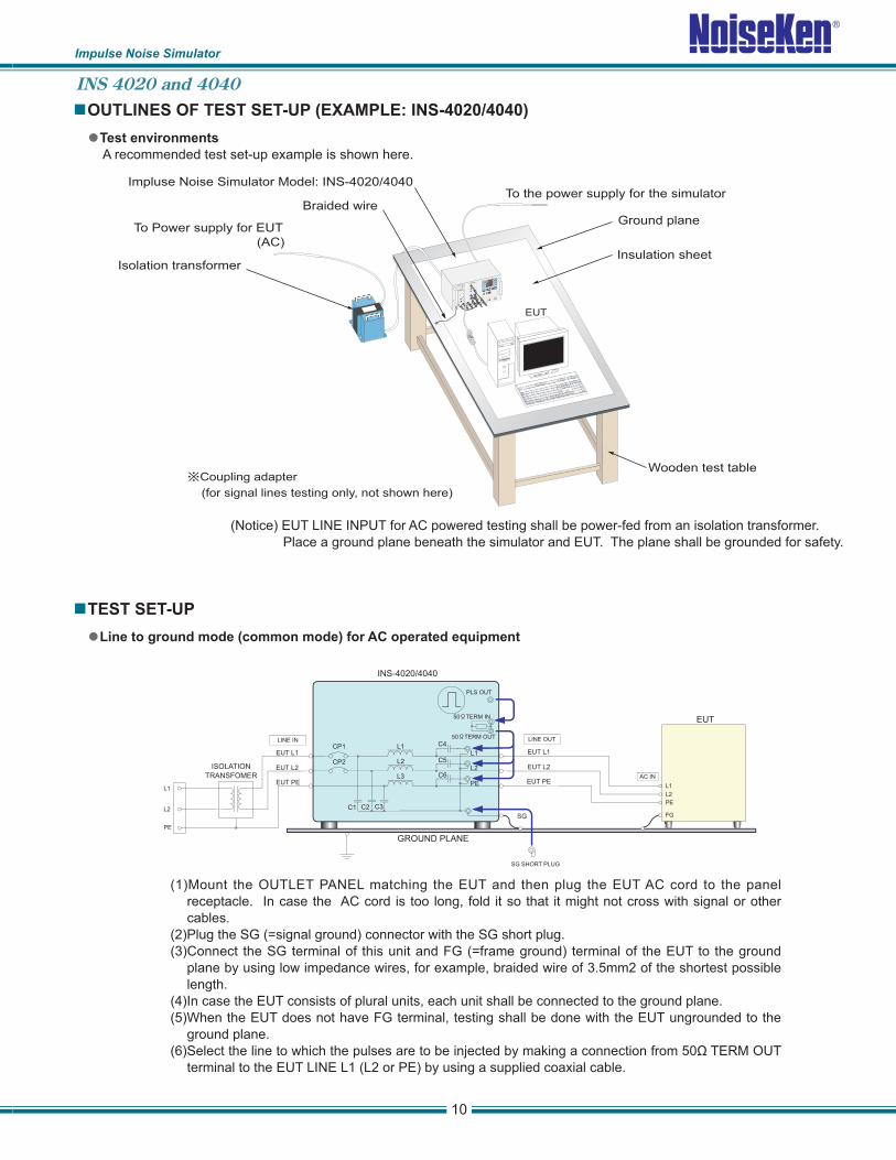
TEST SET-UP
Line to ground mode (common mode) for AC operated equipment
(Notice) EUT LINE INPUT for AC powered testing shall be power-fed from an isolation transformer.
Place a ground plane beneath the simulator and EUT. The plane shall be grounded for safety.
(1)Mount the OUTLET PANEL matching the EUT and then plug the EUT AC cord to the panel
receptacle. In case the AC cord is too long, fold it so that it might not cross with signal or other
cables.
(2)Plug the SG (=signal ground) connector with the SG short plug.
(3)Connect the SG terminal of this unit and FG (=frame ground) terminal of the EUT to the ground
plane by using low impedance wires, for example, braided wire of 3.5mm2 of the shortest possible
length.
(4)In case the EUT consists of plural units, each unit shall be connected to the ground plane.
(5)When the EUT does not have FG terminal, testing shall be done with the EUT ungrounded to the
ground plane.
(6)Select the line to which the pulses are to be injected by making a connection from 50Ω TERM OUT
terminal to the EUT LINE L1 (L2 or PE) by using a supplied coaxial cable.
Test environments
A recommended test set-up example is shown here.
OUTLINES OF TEST SET-UP (EXAMPLE: INS-4020/4040)
INS 4020 and 4040

Impulse Noise Simulator
TEST SET UP
NOISE LABORATORY CO., LTD.
1-4-4, Chiyoda, Sagamihara City,
Kanagawa Pref., 229-0037 Japan
Tel: +81(0)42-712-2051 Fax: +81(0)42-712-2050
http://www.noiseken.co.jp/
E-mail: [email protected] H
(1)Mount the OUTLET PANEL matching the EUT and then plug the EUT AC cord to the panel receptacle.
In case the AC cord is too long, fold it so that it might not cross with signal or other cables.
(2)Testing shall be done with the SG terminal not being connected to the ground plane. In case the
EUT have an FG terminal, test it both with the FG connected to the ground plane and with the FG
disconnected form the plane.
(3)Select the line to which the pulses are to be injected by making a connection from 50ΩTERM OUT
terminal to the EUT LINE L1 (or L2) by using a supplied coaxial cable.
(4)Plug the L2 (or L1) connector with the SG short plug, while the SG connector shall remain open circuit.
Line to line (normal mode) for AC operated equipment
Capacitive coupling test for signal lines (by using CA-805B coupling adapter)
(1)Open the coupling adapter (option) and clamp the interface cable under test. The PULSE OUT
terminal shall be connected to one side of the adapter and the 50ΩTERM IN terminal shall be
connected to the other side. (Changing the injection and termination sides is also recommended as
test results may vary.)
(2)EUT power can be supplied from the service outlet directly, as the HV pulses are not injected to these
lines.
(3)Connect the SG terminal of this unit and FG terminal of each unit of the EUT to the ground plane.
INS 4020 and 4040
Designs and specifi cations are subject to change without notice.