ome201102 gsm bts3012a hardware structure issue1.0
TRANSCRIPT

Huawei Confidential. All Rights Reserved
OME201102 GSM BTS3012A Hardware Structure
ISSUE 1.0

2 Internal Use
ObjectivesObjectives
Upon completion of this course, you will be able to:
Know the functions and features of BTS
Master the BTS hardware structure
Master the cable connection of BTS
3 Internal Use
References References
BTS3012A Technical Manual
BTS3012A Installation Manual
BTS312 User Manual

4 Internal Use
Chapter 1 Overview
Chapter 2 Auxiliary Cabinet
Chapter 3 Main Cabinet
Chapter 4 Antenna and Feeder System

5 Internal Use
LocationLocation
MS: Mobile Station HLR: Home Location Register MSC: Mobile Switching Center VM: Voice Mailbox BTS: Base Transceiver Station AUC: Authentication Center
VLR: Visitor Location Register OMC: Operation and Maintenance Center
EIR: Equipment Identity Register BSC: Base Station Controller SMC: Short Message Center
PSTNISDN
PSPDN
Um Interface
BTS
BTS
BTS
BTS
OMC
HLR/AUC/EIR
BSCMSC/VLR
SMC/VM
A Interface
MAP MAP
TUP,ISUP
MS
MS
MS
6 Internal Use
Features and FunctionsFeatures and Functions
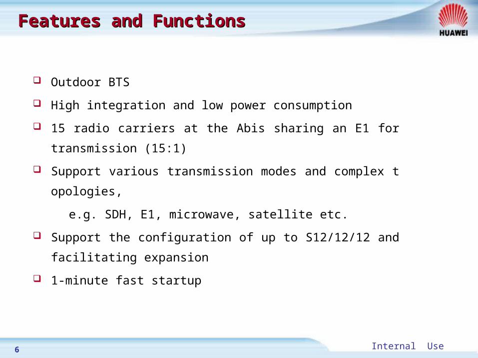
Outdoor BTS
High integration and low power consumption
15 radio carriers at the Abis sharing an E1 for transmission (15:1)
Support various transmission modes and complex topologies,
e.g. SDH, E1, microwave, satellite etc.
Support the configuration of up to S12/12/12 and facilitating expa
nsion
1-minute fast startup

7 Internal Use
Features and FunctionsFeatures and Functions
Support GSM900,DCS1800,EGSM and RGSM
Support GSM PHASE 1 、 PHASE 2 and PHASE 2+
Support GPRS and EDGE
Support baseband hopping and RF hopping
Support FR, HR, EFR and AMR
Support A5/1 and A5/2 encryption/decryption

8 Internal Use
Hardware StructureHardware Structure
DATA_BUS/CONTROL_BUS/TIMING_BUS
TMU
Transmission device
PMU
FH_BUS
CDU
PSU
TRX
TRX
TRX
Signal Processing UnitCommon Unit
CDU
CDU
antenna
antenna
antenna
Antenna Feeder Unit
External control
External alarm
Opt. fiber
XDSL
E1

9 Internal Use
Cabinet and BoardsCabinet and Boards
Boards in Cabinet:
CDU: Combiner & Divider Unit
TRX: Transceiver
PMU: Power Monitoring Unit
TMU: Timing/Transmission &
Management Unit
PSU: Power Supply Unit
TDU: Time Distribution Unit
TCU: Temperature Control Unit
ABB: Abis By-pass Board
TSU: Transmission Power Suppl
y Unit
EMUA: Environment Monitor Un
it Analyzer
Transmission device
Sub-rack
TSU
CDU
CDU
CDU
CDU
CDU
CDU
TRX
TRX
TRX
TRX
TRX
TRX
TRX
TRX
TRX
TRX
TRX
TRX
TCU
PSU
PSU
PSU
PSU
PSU
PMU
PSU
FAN
FAN FAN
FAN
Switch Box
Cable Inlet
AC power distribution
Sub-rack
E1 lighteningProtection sub-rack
DC powerdistribution
Sub-rack
Battery Cabin
Cable Inlet
TMU
ABB
ABB
Auxiliary CabinetAuxiliary Cabinet Main CabinetMain Cabinet

10 Internal Use
Chapter 1 Overview
Chapter 2 Auxiliary Cabinet
Chapter 3 Main Cabinet
Chapter 4 Antenna and Feeder System

11 Internal Use
Auxiliary SystemAuxiliary System
Um
MS
BTS3012A
Auxiliary CabinetMain Cabinet BSC
Abis
Environment monitoring system
Temperature adjustment system
PowerDistribution system
12 Internal Use
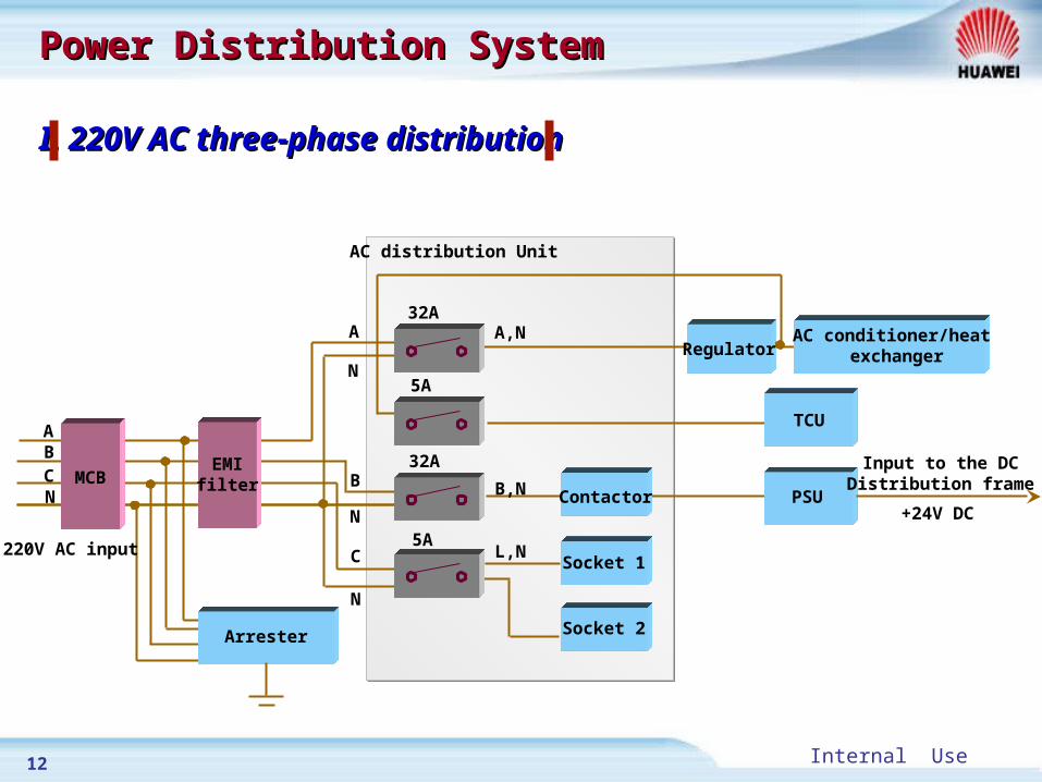
I. 220V AC three-phase distributionI. 220V AC three-phase distribution
Power Distribution SystemPower Distribution System
A
N
N
B
C
N
32A
5A
32A
5A
A,N
B,N
L,N
Contactor
AC distribution Unit
TCU
PSU
Arrester
MCBEMIfilter
220V AC input
+24V DC
Input to the DCDistribution frame
Socket 1
Socket 2
AC conditioner/heat exchanger
ABCN
Regulator

13 Internal Use
II. 220V AC single-phase distributionII. 220V AC single-phase distribution
Power SupplyPower Supply
L
N
N
L
L
N
32A
5A
32A
5A
L,N
L,N
Contactor
AC distribution Unit
TCU
PSU
Arrester
MCBEMIfilter
220V AC input
+24V DC N
Socket 1
Socket 2
Input to DCDistribution frame
AC conditioner/heat exchanger
RegulatorL,N
L

14 Internal Use
III. 110V AC three-phase distributionIII. 110V AC three-phase distribution
Power SupplyPower Supply
A
N
N
B
C
N
32A
5A
32A
5A
B,N
C,N
AC distribution Unit
TCU
PSU
Arrester
MCBEMIfilter
110V AC input
+24V DC
Input to the DCDistribution frame
AC conditioner/heat exchanger
A
B
C
N
Regulator
Transformer
TransformerA,N
Contactor
Socket 1
Socket 2
15 Internal Use
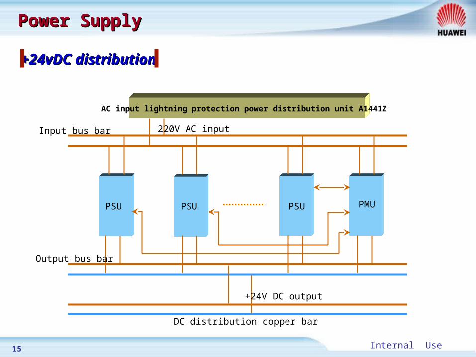
+24vDC distribution+24vDC distribution
Power SupplyPower Supply
AC input lightning protection power distribution unit A1441Z
PSU PSU PSU PMU
+24V DC output
DC distribution copper bar
Output bus bar
Input bus bar 220V AC input

16 Internal Use
PSU ConfigurationPSU Configuration
mode Capacity (TRX) Boards (PSU) Boards (PMU) notes
220/110VAC 1 ~ 3 3 1
One PSU for backup
4 ~ 6 4 1
7 ~ 9 5 1
10 ~ 12 6 1

17 Internal Use
TSU (optional)TSU (optional)
The TSU works under 1+! backup mode. Normally the two TSUs outp
ut equalized current. When one TSU gets faulty, another TSU will sup
ply power to the transmission equipment and report alarms.
-
+24VDC IN+
-
-48VDC IN+
Transmission device
TSUTSU
18 Internal Use
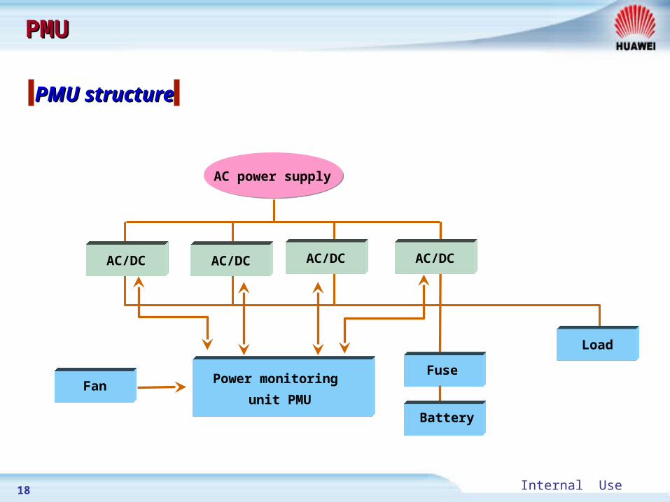
PMU structurePMU structure
PMUPMU
AC/DC
AC power supply
Power monitoring
unit PMUFan
Fuse
Load
AC/DC AC/DC AC/DC
Battery

19 Internal Use
FMUFMU
Fan feeding
Fan revolution speed control
Alarm detection
+24V power supply input interface
Functions of FMUFunctions of FMU

20 Internal Use
TCUTCU
TCU real-time monitors the temperature
in the cabinet. By controlling the power
distribution of the cabinet, it can prevent
the damage of over-high or over-low
temperature to the equipment and
components.
TCU controls the 220V AC input from
the external power supply, the +24V DC
output of the storage batteries
(excluding the power distribution of the
air-conditioner) and the power-on/off
commands for some boards according
to the temperature of the cabinet.
Functions of TCUFunctions of TCU
Sensor
PMU
TCU
TMU
AC lightning protection board
Storage battery
TRX/CDU
Voltage Stabilizer
Air conditioner/heat exchangerMonitoring
Subsystem
Alarm
signals
Control
signals
Control
signals
Temperature Test Access test Water testSmoke test

21 Internal Use
ABB (optional)ABB (optional)
It is in charge of the BTS transmission trunk. When power failure occurs at a c
ertain level (in the middle) of BTS in the chain networking, ABB will bypass the
Abis transmission line off this site, and directly connect it to the downstream B
TS.
ABB can also perform loop back at the transmission line, so that in the case of
power failure at the last level BTS, ABB will loop back the E1 signal for BSC to
detect the quality of the entire transmission link.
Functions of ABBFunctions of ABB
Sites 1 Sites 2 Sites 3
ABBBSC
TMU
ABB
TMU
ABB
TMU

22 Internal Use
ABB (optional)ABB (optional)
Digit 1 Digit 2 Digit 3 Digit 4 Detailed indication
OFF OFF X XNot end site, transmission terminal loopback not sup
ported (default setting)
ON ON X XEnd site, transmission terminal loopback supported
Caution:
The “X” means that the status of switch has no relation with the DIP function.
S2 is not allowed to set as any status apart from the above two .

23 Internal Use
TMUTMU
Provide E1 connection interface
Provide channel multiplexing and flexible networking modes
Provide Man-machine interface (MMI) and operation &
maintenance link
Provide centralized BTS clock
Provide alarm signal input ports
Functions of TMUFunctions of TMU

24 Internal Use
Indictors on TMUIndictors on TMU
Indicator Name
Color Meaning Explanation Normal State
PWR Green PowerOn: Normal
Off: AbnormalOn
RUN Green Running StateFlash(0.5Hz): Normal
On or Off: AbnormalFlash
LI1,2,3,4 GreenE1 Transmission
On: Local Alarm
Flash: Remote Alarm
Off: Normal
Off
M/S GreenMaster/Slave indication
Slow flash(1HZ): Master
Quick flash(2Hz): Slave
Master Board: Slow flash
Slave Board: Quick flash
PLL GreenPhase identification indicator
On: Free oscillation
Quick flash(4Hz): Catching
Slow flash(1Hz): Locked
Off: Abnormal
Slow flash
TMU
MMI
T13M
FCK
T2M
DBG
RST
PWR
M/S
RUN
LI1
LI2
LI3
LI4
PLL

25 Internal Use
Temperature Adjustment SystemTemperature Adjustment System
The heat dissipation and heating under low temperature of
outdoor BTS3012A are accomplished by temperature adjustment
system. The temperature adjustment system has high reliability
performance and reports alarms when faults occur. The
temperature adjustment of BTS3012A is accomplished by the air-
conditioner or the heat exchanger.
26 Internal Use
Chapter 1 Overview
Chapter 2 Auxiliary Cabinet
Chapter 3 Main Cabinet
Chapter 4 Antenna and Feeder System

27 Internal Use
TRXTRX
Baseband speech processing
Um and Abis interface signaling processing
Modulation and demodulation
RF signal amplification
Functions of TRXFunctions of TRX

28 Internal Use
TRX Module StructureTRX Module Structure
TBPU:TRX Baseband signal Processing Unit RPU:RF signal Processing Unit
SCP: Signaling Processing Unit DSP: Digital Signal Processing Unit
CUI: Carrier Unit Interface
TDP: Transmitter Driver and PLL Unit PAU: Power Amplifier Unit
RCU: Receiving Unit
DBUS: Data Bus CBUS: Control Bus
TBUS: Timing Bus
FH_BUS: Frequency Hopping Bus
PAU Transmitter
DBUS
TBUS
SCP CUI
Clock processing partClock processing part
TBPU
DSP
FH_BUS
TDP
RCU
RPU
Receiver
Diversityreceiver
CBUS

29 Internal Use
Output Power of TRXOutput Power of TRX
Normal: 40W(46dBm) or 60W(48dBm)
PBU: 80W(49dBm)
EDGE TRX: GMSK: 60W, 8PSK: 40W

30 Internal Use
When the standing wave ratio at the power amplifier output port
exceeds 1.5, it reports standing wave alarm to the baseband unit
When the temperature of the power amplifier exceeds 85 , the p℃ower amplifier unit reports the over-temperature alarm via the bas
eband unit, and automatically turns off the power amplifier
Over standing wave alarmOver standing wave alarm
Over-temperature alarmOver-temperature alarm
Alarms of TRXAlarms of TRX

31 Internal Use
Indicators on TRXIndicators on TRX
Indicator Name
Color Meaning ExplanationNormal State
PWR Green PowerOn: Normal
Off: AbnormalOn
RCP GreenSCP Running State
Flash(0.5Hz): Normal
On or Off: Abnormal
Flash
RDP GreenDSP Running State
Flash(0.5Hz): Normal
On or Off: Abnormal
Flash
FAIL RedAlarm Indicator
On: Alarm
Off: No alarmOff
TX OUT
PWR
RCP
RDP
FAIL
RST
MMI
RXA IN
RXB IN
TRX

32 Internal Use
CDUCDU
Combine and filter transmitted signals
Filter ,amplify and distribute received signals
Provide power for the tower-top amplifier
Alarm detection
Functions of CDUFunctions of CDU

33 Internal Use
CDU StructureCDU Structure
Combiner
Divider
Divider
DuplexerTX1
TX2
TX-COMBTX-DUP
RX1RX2RX3RX4
HL-out
RX6RX7RX8
RX5
HL-in
RXD-ANT
TX/RX-ANT
RXD-out
LNA
LNA Filter
34 Internal Use
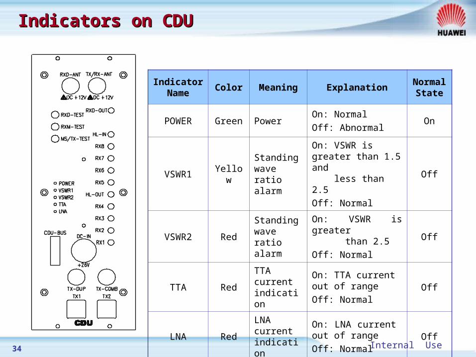
Indicators on CDUIndicators on CDU
Indicator Name
Color Meaning ExplanationNormal State
POWER Green PowerOn: Normal
Off: AbnormalOn
VSWR1 YellowStanding wave ratio alarm
On: VSWR is greater than 1.5 and less than 2.5
Off: Normal
Off
VSWR2 RedStanding wave ratio alarm
On: VSWR is greater than 2.5
Off: NormalOff
TTA RedTTA current indication
On: TTA current out of range
Off: NormalOff
LNA RedLNA current indication
On: LNA current out of range
Off: NormalOff

35 Internal Use
Rear Panel of CDURear Panel of CDU
MAIN: TTA power feeding selection knob of main receiving channel
DIVERSE: TTA power feeding selection knob of diversity receiving channel
FUSE :1.5A
Setting MAIN DIVERSE Unit
0 off off
1 100 65 mA
2 107 100 mA
3 205 205 mA
Correspondence between knob setting and current strength of TTA
Note: MAIN is recommended to be set at 1(100mA),and DIVERSE to be set at 2(100mA).Other modes of setting are not recommended

36 Internal Use
Alarm DetectionAlarm Detection
VSWR (Voltage Standing Wave Ratio) monitoring: CDU Monitors the
status of antenna system. When the detected standing wave ratio
exceeds the preset threshold (1.5 or 2.5), CDU will generate
corresponding alarms
Low noise amplifier fault alarm: The signal is extracted from the
power supply current of the low noise amplifier. When the current
exceeds a certain level ,alarm signals are generated
Tower-top amplifier alarm: When there is a tower-top amplifier on
service, the CDU monitors the status of tower-top amplifier by its
working current. If the current exceeds a certain level , alarm signals
are generated
37 Internal Use
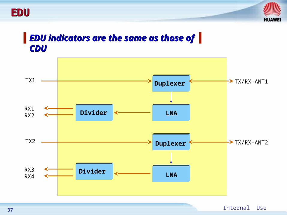
EDUEDU
EDU indicators are the same as EDU indicators are the same as those of CDUthose of CDU
Divider
DuplexerTX1
RX1RX2
TX/RX-ANT1
Divider
DuplexerTX2
RX3RX4
TX/RX-ANT2
LNA
LNA
38 Internal Use
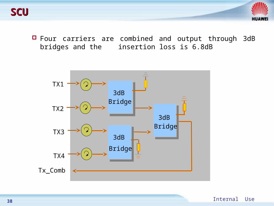
SCUSCU
Four carriers are combined and output through 3dB bridges and the insertion loss is 6.8dB
Tx_Comb
TX4
TX3
TX2
TX1
3dB
Bridge
3dBBridge
3dBBridge

39 Internal Use
Chapter 1 Overview
Chapter 2 Auxiliary Cabinet
Chapter 3 Main Cabinet
Chapter 4 Antenna and Feeder System

40 Internal Use
S1/1/1S1/1/1
TX OUT
RXA
RXB
DUP
1:4
1:4
TX/RX ANT
TX
RX
HL OUT
HL IN
COMB
TX COMB
TX DUP
RXD OUT
RXD ANT
(RXB)
(TX/RXA)
41 Internal Use
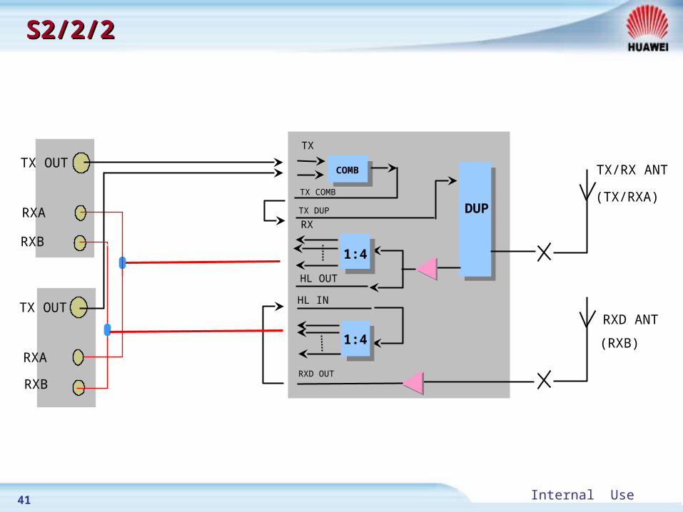
S2/2/2S2/2/2
TX OUT
RXA
RXB
DUP
1:4
1:4
TX/RX ANT
TX OUT
RXA
RXB
TX
RX
HL OUT
HL IN
COMB
TX COMB
TX DUP
RXD OUT
RXD ANT
(RXB)
(TX/RXA)

42 Internal Use
S4/4/4 2CDUS4/4/4 2CDU
Duplexer
Distributor Distributor Distributor DistributorCombiner Combiner
Duplexer

43 Internal Use
S4/4/4 SCU+CDUS4/4/4 SCU+CDU
TX OUT
RXA
RXB
TX OUT
RXA
RXB
TX
COMB
TX COMB
TX OUT
RXA
RXB
DUP
1:4
1:4
TX/RX ANT
TX OUT
RXA
RXB
TX
RX
HL OUT
HL IN
COMBTX COMB
TX DUP
RXD OUT
SCU
RXD ANT
(TX/RXB)
(RXA)
CDU

44 Internal Use
2CDU+SCU2CDU+SCU
Duplexer Duplexer
Combiner Combiner DistributorDistributorDistributor Distributor Combiner Combiner
Combiner

45 Internal Use
Lightning Arrester is used to
prevent the equipment from
being damaged by the
lightening current inducted
by the core line of the feeder
feeder
jumper
Lightning ArresterLightning Arrester
Lightning Arrester
46 Internal Use
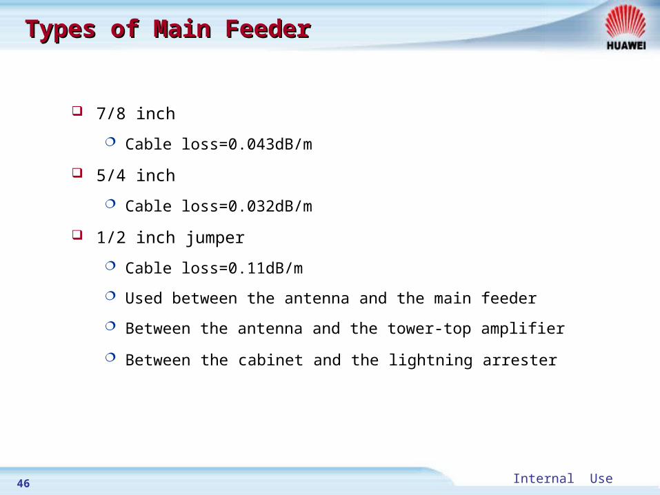
Types of Main FeederTypes of Main Feeder
7/8 inch
Cable loss=0.043dB/m
5/4 inch
Cable loss=0.032dB/m
1/2 inch jumper
Cable loss=0.11dB/m
Used between the antenna and the main feeder
Between the antenna and the tower-top amplifier
Between the cabinet and the lightning arrester

47 Internal Use
TTA (Optional)TTA (Optional)
The tower-top amplifier is installed close to the receiving antenna
It can be used to increase the receiving sensibility of the base statio
n
Consisting of:
Simplex TTA
Duplex TTA
Triplex TTA

48 Internal Use
TTA (Optional)TTA (Optional)
antenna
simplex TTA duplex TTA triplex TTA
Low noise amplifier
TX filter
bypassBias TeeBTS
triplex TTA
DC
RX filterRX filter

49 Internal Use
Antenna PatternAntenna Pattern
The antenna pattern describes the radiating abilities of antennas in all
directions
360¡ ã
Omni Antenna Directional antenna
120¡ ã 90¡ ã 65¡ ã
50 Internal Use
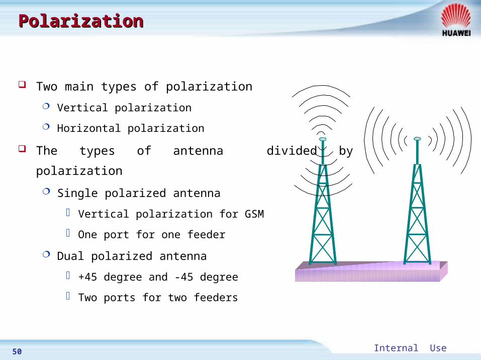
PolarizationPolarization
Two main types of polarization
Vertical polarization
Horizontal polarization
The types of antenna divided by polarization
Single polarized antenna
Vertical polarization for GSM
One port for one feeder
Dual polarized antenna
+45 degree and -45 degree
Two ports for two feeders
51 Internal Use
SummarySummary
Functions and features of BTS BTS hardware structure Antenna and feeder system
SummarySummary

Huawei Confidential. All Rights Reserved