operating instructions. kavo prophycenter® 1058 p. · 2014-03-20 · safety checks for primus 1058...
TRANSCRIPT
Operating Instructions.KaVo PROPHYcenter® 1058 P.
Always on the safe side.

Vertrieb/distribution:KaVo Dental GmbHBahnhofstraße 20 • D-88447 WarthausenTel.: 0 73 51 / 56-0 • Fax: 0 73 51 / 1 22 14
Hersteller/manufacturer:Kaltenbach & Voigt GmbHBismarckring 39D-88400 Biberach
0
12
4
11
KaVo PROPHYcenter® 1058 P
A 1 User information . . . . . . . . . . . . . . . . . . . . . . . . . . . . . . . . . . . . . . . . . . . . . . . . . . . . . . . . . . . . . . . . . . . . . . . . . . . . . . .3A 1.1 Meaning of the pictograms ....................................................................................................................................3A 1.2 Important information ............................................................................................................................................3A 1.3 Requirements for proper technical operation ........................................................................................................3A 1.4 Safety checks ........................................................................................................................................................3A 1.5 Purpose and potential applications ......................................................................................................................4A 1.6 Customer Service ..................................................................................................................................................5
A 2 Description of unit . . . . . . . . . . . . . . . . . . . . . . . . . . . . . . . . . . . . . . . . . . . . . . . . . . . . . . . . . . . . . . . . . . . . . . . . . . . . . .6A 2.1 Dental chair ............................................................................................................................................................6A 2.2 Dental chair COMPACTchair ..................................................................................................................................6A 2.3 Unit base ................................................................................................................................................................7A 2.4 Unit body with patient's part ..................................................................................................................................7A 2.5 A 2.4 Assistant's element ......................................................................................................................................8A 2.6 Dentist's element ....................................................................................................................................................8A 2.7 Control panel ..........................................................................................................................................................9A 2.8 Rating plate and type plates ................................................................................................................................10
A 3 General operation . . . . . . . . . . . . . . . . . . . . . . . . . . . . . . . . . . . . . . . . . . . . . . . . . . . . . . . . . . . . . . . . . . . . . . . . . . . . .11A 3.1 Main switch ..........................................................................................................................................................11
A 4 Operation of multifunction footcontrol . . . . . . . . . . . . . . . . . . . . . . . . . . . . . . . . . . . . . . . . . . . . . . . . . . . . . . . . . . . .12A 4.1 Control elements ..................................................................................................................................................12
A 5 Operation of dental chair . . . . . . . . . . . . . . . . . . . . . . . . . . . . . . . . . . . . . . . . . . . . . . . . . . . . . . . . . . . . . . . . . . . . . . .13A 5.1 Arm rest for Primus patient chair ........................................................................................................................13A 5.2 Armrest for COMPACTchair patient chair (additional equipment) ......................................................................13A 5.3 Primus patient chair seat adjustment for the treatment of children ......................................................................13A 5.4 Operation of the headrest ....................................................................................................................................14A 5.5 Removing the head upholstery ..........................................................................................................................14A 5.6 two-joint headrest (Dental chair COMPACTchair) .............................................................................................. 15A 5.7 Turning the head upholstery ................................................................................................................................15A 5.8 Safety cut-out ......................................................................................................................................................16A 5.9 Motor assistance for headrest / patient`s component COMPACTchair ................................................................17A 5.10 Chair position adjustment for Primus ..................................................................................................................21A 5.11 Chair position adjustment for COMPACTchair ....................................................................................................22A 5.12 Calling up automatic chair positions......................................................................................................................23
COMPACTchair and Primus patient chair ............................................................................................................23A 5.13 Saving of automatic chair movements ................................................................................................................24
COMPACTchair and Primus patient chair ............................................................................................................24A 5.14 Special chair functions ........................................................................................................................................25
A 6 Dentist's element . . . . . . . . . . . . . . . . . . . . . . . . . . . . . . . . . . . . . . . . . . . . . . . . . . . . . . . . . . . . . . . . . . . . . . . . . . . . . .26A 6.1 Movement of the dentist's element ......................................................................................................................26A 6.2 Switching between the memory level dentist 1 / dentist 2 ..................................................................................26A 6.3 Spittoon bowl and tumbler filler ............................................................................................................................27A 6.4 X-ray viewer (kit) ..................................................................................................................................................27A 6.5 Hydroclean ..........................................................................................................................................................27A 6.6 Priority circuit ........................................................................................................................................................28
A 7 Settings and handling of the instrument . . . . . . . . . . . . . . . . . . . . . . . . . . . . . . . . . . . . . . . . . . . . . . . . . . . . . . . . . . .29A 7.1 Memory level selection with Memospeed (kit) ....................................................................................................29A 7.2 Settings on the turbine ........................................................................................................................................30
Setting on the turbine with Memospeed ..............................................................................................................31A 7.3 Settings on the INTRA K 200 motor / KL 701 motor ............................................................................................32
Settings on the INTRA K 200 motor/ KL 701 motor with Memospeed ................................................................33A 7.4 Settings on the PIEZOlux ....................................................................................................................................34
Settings on the PIEZOlux with Memospeed ........................................................................................................34A 8 Handling of the three- and multifunction handpiece . . . . . . . . . . . . . . . . . . . . . . . . . . . . . . . . . . . . . . . . . . . . . . . . .35A 9 Handling POLYlux II . . . . . . . . . . . . . . . . . . . . . . . . . . . . . . . . . . . . . . . . . . . . . . . . . . . . . . . . . . . . . . . . . . . . . . . . . . . .37A 10 Time settings on the Memospeed . . . . . . . . . . . . . . . . . . . . . . . . . . . . . . . . . . . . . . . . . . . . . . . . . . . . . . . . . . . . . . . .37
A 10.1 Setting the time ....................................................................................................................................................37A 10.2 Setting the timer ..................................................................................................................................................37A 10.3 Handling function keys ..........................................................................................................................................38
A 11 Assistant's element with patient's part . . . . . . . . . . . . . . . . . . . . . . . . . . . . . . . . . . . . . . . . . . . . . . . . . . . . . . . . . . . .38A 11.1 Moving the patient's part and assistant's element ..............................................................................................38A 11.2 Handling of the suction tubings ............................................................................................................................39A 11.3 Vacu-Stop ............................................................................................................................................................39A 11.4 Spittoon bowl and tumbler filler ............................................................................................................................39
A 12 Elimination of faults . . . . . . . . . . . . . . . . . . . . . . . . . . . . . . . . . . . . . . . . . . . . . . . . . . . . . . . . . . . . . . . . . . . . . . . . . . .40A 13 Adaptable accessories and kits . . . . . . . . . . . . . . . . . . . . . . . . . . . . . . . . . . . . . . . . . . . . . . . . . . . . . . . . . . . . . . . . . .42
A 13.1 Unit base ..............................................................................................................................................................42A 13.2 Patient’s chair ......................................................................................................................................................42A 13.3 Patient’s part with unit body and assistant’s element ..........................................................................................42A 13.4 Dentist’s element ..................................................................................................................................................42
Technical date . . . . . . . . . . . . . . . . . . . . . . . . . . . . . . . . . . . . . . . . . . . . . . . . . . . . . . . . . . . . . . . . . . . . . . . . . . . . . . . . . . . . .43Safety checks for Primus 1058 P . . . . . . . . . . . . . . . . . . . . . . . . . . . . . . . . . . . . . . . . . . . . . . . . . . . . . . . . . . . . . . . . . . . . . .44
22
KaVo PROPHYcenter® 1058 P
KaVo Dental Ltd.Industrial EstateRaans RoadAmersham Bucks. HP6 6JLEnglandTel. ++ 44 / 14 94 / 73 30 00Fax ++ 44 / 14 94 / 43 11 68e-mail: [email protected]
KAVO FRANCEZAC PARIS NORD IIParc des RefletsBP 4004495912 ROISSY CDG CedexFRANCETel. ++ 33 / 1 / 56 48 72 00Fax ++ 33 / 1 / 56 48 72 05e-mail: [email protected]
KaVo Dental S.A.c/o Joaquín María López 4128015 MadridSpanienTel. ++ 34 / 91 / 5 49 37 00Fax ++ 34 / 91 / 5 43 70 54
KaVo AustriaDentalwarenhandels GmbHGutheil-Schoder-Gasse 7AA-1100 WienTel. ++ 43 / 1 / 66 50 13 30Fax ++ 43 / 1 / 66 50 13 317e-mail: [email protected]
KaVo Scandinavia ABOptimusvägen 12 BS-194 84 Upplands VäsbySchwedenTel. ++ 46 / 85 9 / 00 47 00Fax ++ 46 / 85 9 / 0047 10e-mail: [email protected]
KaVo Benelux S.A.Allée de la Recherche 10B-1070 BruxellesTel. ++ 32 / 2 / 5 20 44 70Fax ++ 32 / 2 / 5 20 69 67
KaVo Nederland B.V.Hagenweg 7 C4131 LX VianenNiederlandeTel. ++ 31 / 34 73 / 7 36 56Fax ++ 31 / 34 73 / 7 75 96e-mail: 106053.3166@
compuserve.com
KaVo Dental AG Steinbruchstraße 11 5200 Brugg 3SchweizTel. ++ 41 / 56 / 460 78 78Fax ++ 41 / 56 / 460 78 79e-mail: [email protected]
KaVo Italia S.p.A.Via R. Merello, 8/AI-16141 GenovaItaliaTel. ++ 39 / 0 / 10 / 8 33 21Fax ++ 39 / 0 / 10 / 8 33 22 10e-mail: [email protected]
KaVo Dental GmbHBahnhofstr. 20
D-88445 WarthausenD-88447 Warthausen
Tel. ++ 49 / 73 51 / 56 - 0Fax ++ 49 / 73 51 / 1 22 14
KaVo Dental GmbHBismarckring 39
D-88396 BiberachD-88400 Biberach
Tel. ++ 49 / 73 51 / 56 - 0Fax ++ 49 / 73 51 / 56 16 27e-mail: [email protected]
KaVo Dental Russland GmbHnab. reki Fontanki, 130 A198005 St. PetersburgRußlandTel: ++7 / 812 / 259 66 43
++7 / 812 / 251 01 98Fax: 007 812 / 251 06 55e-mail: [email protected]
KaVo DentalASIA-PACIFIC (Pte.) Ltd.7500 A, Beach RoadNo. 09-303/309The Plaza / Singapore 199591Tel. ++ 65 / 62 96 17 90Fax ++ 65 / 62 97 29 58e-mail: [email protected]
KaVo America Corp.340 East Main StreetLake Zurich, Illinois 60047USATel. ++ 1 / 8 47 / 5 50 68 00Fax ++ 1 / 8 47 / 5 50 68 25e-mail: [email protected]
KaVo Dental SupplyMalaysia (SDN) BHDNo. 50, Jalan SS 26/11Taman Mayang Jaya47301 Petaling Jaya, SelangorMalaysiaTel. ++ 60 / 3 / 703 32 90Fax ++ 60 / 3 / 703 24 64e-mail: [email protected]
KaVo do Brasil Ind. Com. Ltda.Rua Chapecó, 8689221-040 - Joinville - SCBrasilTel.: ++55 47 451 0100Fax: ++55 47 451 0214www.kavo.com.bre-mail: [email protected]
KaVo CZ spol. s. r.o.Nezarecka 85/IV.37701 Jindrichuv HradecTschechische RepublikTel. ++ 420 / 3 84 - 36 24 65Fax ++ 420 / 3 84 - 36 20 48e-mail: [email protected]
KaVo Dental (India) Pvt. Ltd.301, SigmaHiranandani Business ParkPowaiMumbai - 400 076IndiaTel. ++ 91 / 22 / 56 60 64 64Fax ++ 91 / 22 / 56 60 65 65
KaVo ChinaService and Sales officeBlock 2 Huiwan Overseas-Chinese ApartmentsArea 3 of HuianliChaoyang District # 12-03Unit 2Beijing 100101Tel. ++ 86 / 10 64 / 91 65 87Fax ++ 86 / 10 64 / 91 65 87
KaVo Polska sp.z.o.o.ul. Pomorska 251 P 40592-214 LodzPolskaTel. ++ 48 / 42 / 6 75 75 36Fax ++ 48 / 42 / 6 75 75 36
KaVo OsakaYotsubashi Okawa Building11 Fl. 1-6-23, ShinmachiNishi-KuOsaka 550-0013JapanTel. ++ 81 / 6 / 65 38 58 50Fax ++ 81 / 6 / 65 38 58 55e-mail: [email protected]
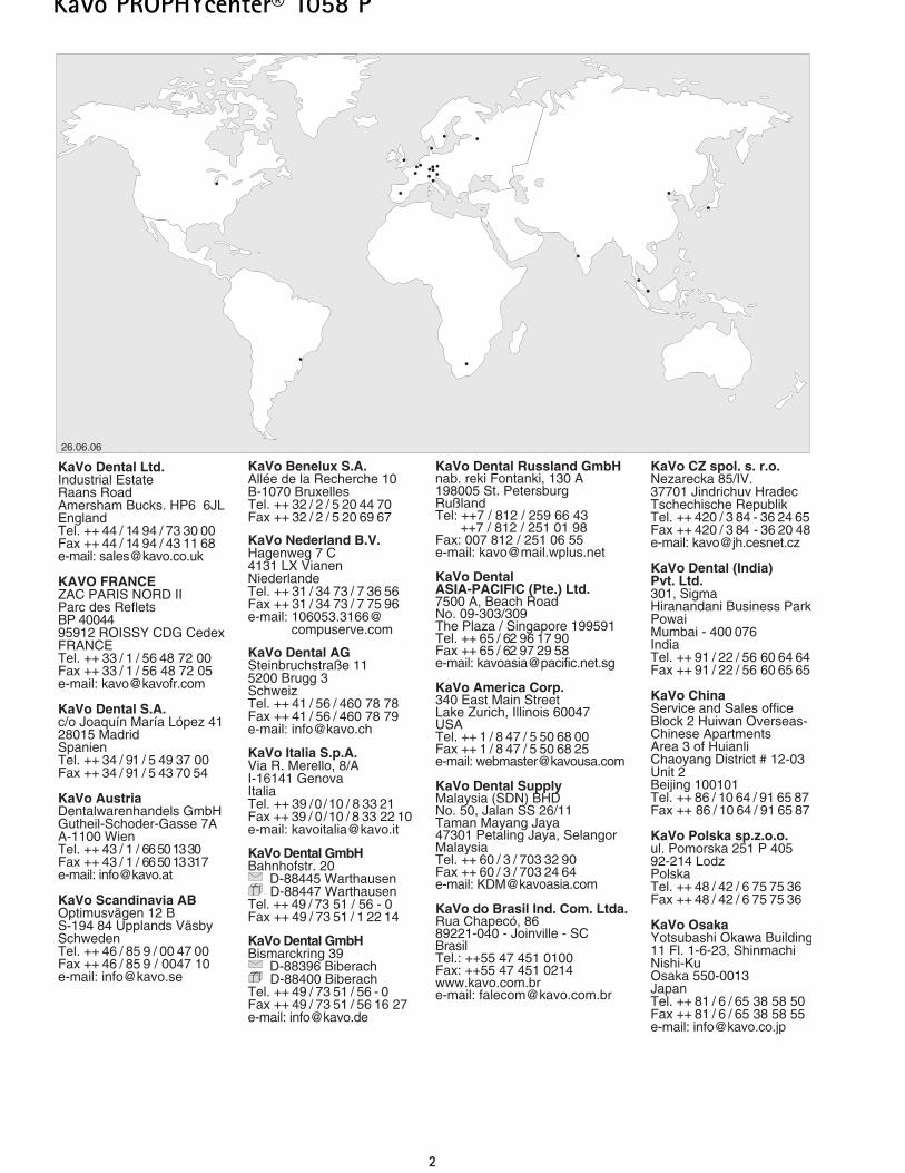
26.06.06
33
KaVo PROPHYcenter® 1058 P
A 1 User information
A 1.1 Meaning of the pictograms
Situation which may lead to danger,damage to material or to operating
faults if the information is ignored.
Important information for operatorand engineer.
A 1.2 Important information
The KaVo PROPHYcenter 1058 P is adental treatment unit according to ISO
74 94 with a dental chair according to ISO68 75.
The operating instructions should beread by the user before the unit is put
into operation for the first time, in order toavoid incorrect operation and other damage.If further language versions are required,please request these from your responsibleKaVo agent.
Duplication and distribution of the operatingand assembly instructions/engineers'instructions require the prior consent of KaVo.All technical data, information and propertiesof the equipment described in these instruc-tions were compiled to the best of our knowl-edge and correspond to the state on goingto press.
The product may be modified on the basisof new technical developments.This does not imply a right to upgrading ofexisting units.
KaVo assumes no responsibility for dam-age arising from:• external effects (poor quality of the media
or poor installation),• use of incorrect information,• use of the unit for purposes other
than the intended purpose,• improperly performed installation, com-
missioning and repairs.
The following are authorized to repair andmaintain KaVo products:• the engineers of KaVo agents
throughout the world,• those engineers of the KaVo dealers
who have been specially trained by KaVo,• independent Service Technicians specially
trained by KaVo.
The approvals shall become null and voidif the unit is modified by third parties.
A 1.3 Requirements for proper tech-nical operation
Responsibility shall be assumed for thesafety, reliability and performance of theunit if
• installation, extensions, adjustments, modi-fications or repairs are carried out by per-sons trained by KaVo and the installationwas reported to KaVo by means of a trans-fer protocol,
• the electrical installation of the relevantroom meets the requirements and specifi-cations according to VDE 0100-710
• and the unit is operated in conformity withthe operating instructions.
It is advisable to use only KaVo originalspare parts for operation and for repair
since these are subjected to extensive testswith regard to their safety, function andspecific suitability.
Legal provisions
The general guidelines and/or national lawsapplicable to medical products, nationalregulations and the rules of the industryshould be applied to the KaVo product forcommissioning and during operation inaccordance with the prescribed purpose andshould be fulfilled.
INTRA LUX motor K200/INTRA LUXmotor KL 701
The mode 2 min operation/5 min pauserepresents the possible limiting load of themotor (full load at maximum speed). Inpractice, pulsed loads lasting for secondsand pauses lasting for seconds to minutesare realistic, the maximum possible motorcurrent usually not being reached. This cor-responds to the usual dental procedure.
A 1.4 Safety checks
PROPHYcenter 1058 P unit system is notapproved for operation in areas where thereis a risk of explosion. Each time before the unit is used, theuser must be sure of the operational safetyand proper condition of the unit. Never continue working with damagedfunctional parts. Instrument tubing may not be treatedwith adhesive. Instrument tubing must be regularly sub-jected to visual inspection and must bereplaced immediately if damaged. Repairs to instrument tubing may be per-formed only by the persons mentioned inSection A 1.2. The insufflation of spray air or blown airinto open wounds in the operation areamust be avoided since otherwise there isthe danger of air embolism or cutaneousemphysema. Because of stagnation, water- or air-con-veying lines in treatment units must beflushed or blown through before initial operation andafter standing times (weekend, public holi-day, vacation, etc.). Remove every hand-piece/motor (without attached instrument)from the holder and operate alternatelywith water and air. Operate the tumbler filler several times. After the end of the treatment, removerotating instruments from turbines, straightand contra-angle handpieces and treatmentheads. Never change the scaler tip without akey – risk of injury and infection. Before leaving the practice, switch offthe main switch. In the case of new installations and aftermaintenance work, interventions andrepairs on the product, the unit must bemade ready for operation in accordancewith VDE 0751-1 (according to the state ofthe art) before being put into operation again.
44
KaVo PROPHYcenter® 1058 P
Further annual measures:
Visual inspection based on DIN EN ISO6875, DIN EN ISO 7494 and DIN EN60601-1 for:• Mechanical stability of the unit• Proper movement sequences of the compo-
nents of the unit• Stability and mechanical intactness of the
spring arms• Intactness of the housing claddings and
covers• Penetrated moisture and abrasion of the
connections
To ensure continuous availability andvalue of your KaVo treatment unit we
suggest that you have it serviced, by a qua-lified KaVo Service Engineer, annually.
During the maintenance work, all safetydevices should be checked by the serviceengineer:• Braking and locking devices• End positions and stopping devices of mov-
ing parts• Safety system of the building water con-
nection according to DIN 1988-4 and DINEN 1717
Interference with electromedical equip-ment by radio telephones
To ensure the operational safety of elec-tromedical devices, it is advisable to pro-hibit the operation of mobile telephones inthe area of the practice or clinic.
Cardiac pacemakers
Risks caused by electromagneticfields.
Electromagnetic fields may interfere withthe functions of implanted systems (such aspacemakers). Consult the patient before treatment.
References:
• Machtens, E.: Die zahnärtzliche Behandlung von Patienten mit Herzschrittmachern. Dtsch. zahnärztl. Z. 38: 1048 - 1052 (1983).
• Wahl, G.: Diskussionsbeitrag zu Machtens zur Beeinflußbarkeit von Herzschrittmachern in der zahnärztlichen Praxis. Dtsch. zahnärztl. Z. 42: 11 -16 (1987)
• Aderhold, L. , J. Kreuzer: Untersuchungen zur Beeinflußbarkeit vonHerzschrittmachern in der zahnärztlichen Praxis. Dtsch. zahnärztl. Z. 42: 11 - 16 (1987)
Electromagnetic compatibility
In accordance with legal stipulations gov-erning electromagnetic compatibility (EMC-DIN EN 6061-1-2,of October 2002),wemust point out that:• Electrical medical devices are subject to
special EMC safety measures and,as aresult,the KaVo Assembly instructions mustbe closely adhered to.• Portable and mobile high-frequency elec-
tronic communications equipment mayinterfere with electrical medical devices.
• Further information about technical elec-tromagnetic compatibility requirementscan be provided upon request.
Disposal of wastes and residues from theunit and the accessories at the end of theservice life
The resultant wastes should be recycled ordisposed of in such a way that they presentno danger for people and the environment,the applicable national regulations beingcomplied with. In the event of queries,please contact your nearest KaVo agent(see Overview A 1.6).
Please note that the EC Directive onwaste electrical and electronic equip-
ment applies to this product. Within Europetherefore, this product must undergo specialdisposal.Full processing (disinfection /_sterilisation)must be performed before disassembly /disposal of the product, as laid down in the“Processing Methods” Section.For more detailed information about this,please contact KaVo or your specialist den-tal supplier.
A 1.5 Purpose and potential applica-tions
Instruments
Motors and turbines, as well as straight andcontra-angle handpieces, are designed onlyfor dental treatment.It is therefore necessary to consult theappropriateinformation in the respective instructionsfor the instruments.
For technicians' work where a pressurehigher than that during work in the oralcavity is required, for example when grind-ing prostheses, etc., a special technicians'machine must be used. Stronger bearingshave been used in these machines.
Dental chair
The maximum load of 135 kg for the lift-ing movement must not be exceeded.
Loading of the tray support
The maximum loading of the table traysupports is dependent on the instrumentsused.
In principle, the following basic values(free load) may be assumed:
1058 T dentist's element 2 kg
Assistant's tray support 1 kg
These values must not be exceeded.
55
KaVo PROPHYcenter® 1058 P
A 1.6 Customer Service
Technical support for the KaVo equipmentis provided by your dental depot.
The dental depot engineers trained byKaVo constantly take part in training cours-es and special advanced training courses atthe factory and are familiar with the entireKaVo product range.
In order to ensure that the KaVo equipmentis always ready for operation and maintainsits value, the recommended maintenanceservices should be regularly performed.
In Germany, it is mandatory for all operators,equipment supervisors and handlers to operateequipment in compliance with the stipulationsof the German Medical Devices Act.Maintenance services incorporate all the testingactivities stipulated in § 6 of the GermanOrdinance on Operating Medical Devices (MPBetreiber V).
In the event of queries, please contact:
KaVo Dental GmbHCustomer Service CenterBahnhofstr. 2088447 WarthausenGermanyTel.: 0 73 51 - 56 0Instruments Division Tel.: 0 7351-56 1500Equipment Division Tel.: 0 7351-56 2500
In the event of queries, always indicate theexact unit type designations and serial num-bers.
66
KaVo PROPHYcenter® 1058 P
A 2 Description of unit
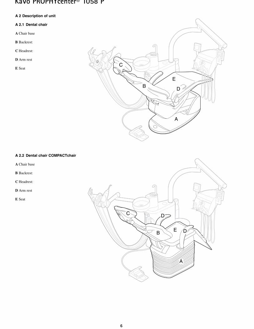
A 2.1 Dental chair
A Chair base
B Backrest:
C Headrest:
D Arm rest
E Seat
A 2.2 Dental chair COMPACTchair
A Chair base
B Backrest:
C Headrest:
D Arm rest
E Seat
B
A
C
D
E
A
B
C
D
D
E
77
KaVo PROPHYcenter® 1058 P
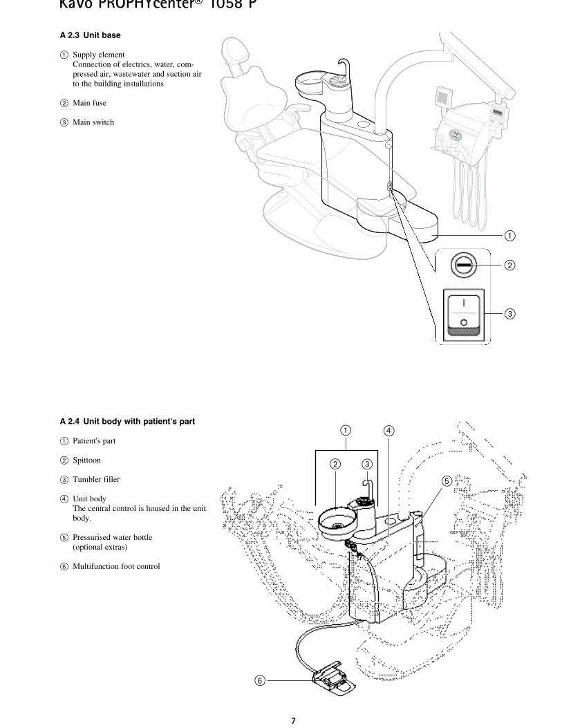
A 2.3 Unit base
@ Supply element Connection of electrics, water, com-pressed air, wastewater and suction airto the building installations
” Main fuse
# Main switch
A 2.4 Unit body with patient's part
@ Patient's part
” Spittoon
# Tumbler filler
£ Unit bodyThe central control is housed in the unitbody.
fi Pressurised water bottle(optional extras)
Ì Multifunction foot control
@
”
£
Ì
fi
#
@
#
”
88
KaVo PROPHYcenter® 1058 P
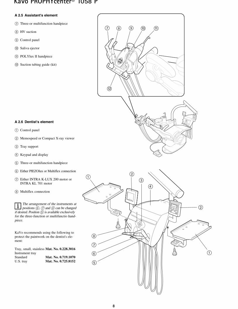
A 2.5 Assistant's element
\ Three-or multifunction handpiece
| HV suction
· Control panel
¯ Saliva ejector
» POLYlux II handpiece
„ Suction tubing guide (kit)
A 2.6 Dentist's element
@ Control panel
” Memospeed or Compact X-ray viewer
# Tray support
£ Keypad and display
fi Three-or multifunction handpiece
Ì Either PIEZOlux or Multiflex connection
\ Either INTRA K-LUX 200 motor orINTRA KL 701 motor
| Multiflex connection
The arrangement of the instruments atpositions Ì, \ and | can be changed
if desired. Position fi is available exclusivelyfor the three-function or multifunctio hand-piece.
KaVo recommends using the following toprotect the paintwork on the dentist's ele-ment:
Tray, small, stainless Mat. No. 0.228.3016Instrument tray Standard Mat. No. 0.719.1070U.S. tray Mat. No. 0.725.8152
#”
@
fi
£
\
Ì
|
@
”
| · 0\ q
„
99
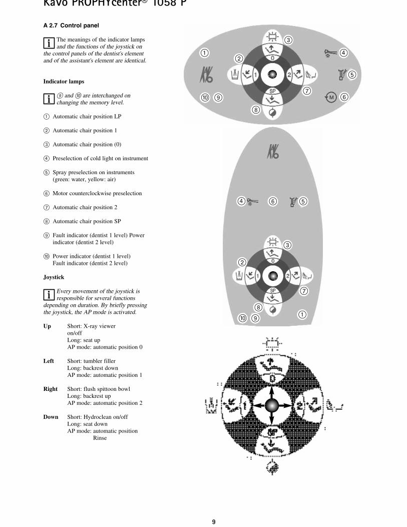
A 2.7 Control panel
The meanings of the indicator lampsand the functions of the joystick on
the control panels of the dentist's elementand of the assistant's element are identical.
Indicator lamps
· and ¯ are interchanged on changing the memory level.
@ Automatic chair position LP
” Automatic chair position 1
# Automatic chair position (0)
£ Preselection of cold light on instrument
fi Spray preselection on instruments(green: water, yellow: air)
Ì Motor counterclockwise preselection
\ Automatic chair position 2
| Automatic chair position SP
· Fault indicator (dentist 1 level) Powerindicator (dentist 2 level)
¯ Power indicator (dentist 1 level)Fault indicator (dentist 2 level)
Joystick
Every movement of the joystick isresponsible for several functions
depending on duration. By briefly pressingthe joystick, the AP mode is activated.
Up Short: X-ray viewer on/offLong: seat up AP mode: automatic position 0
Left Short: tumbler fillerLong: backrest downAP mode: automatic position 1
Right Short: flush spittoon bowlLong: backrest upAP mode: automatic position 2
Down Short: Hydroclean on/offLong: seat downAP mode: automatic position
Rinse
Ì
|·
fi
\
@
”
#
£
KaVo PROPHYcenter® 1058 P
Ì
|
·
fi
\
@”
#
£
¯
¯
1100
KaVo PROPHYcenter® 1058 P
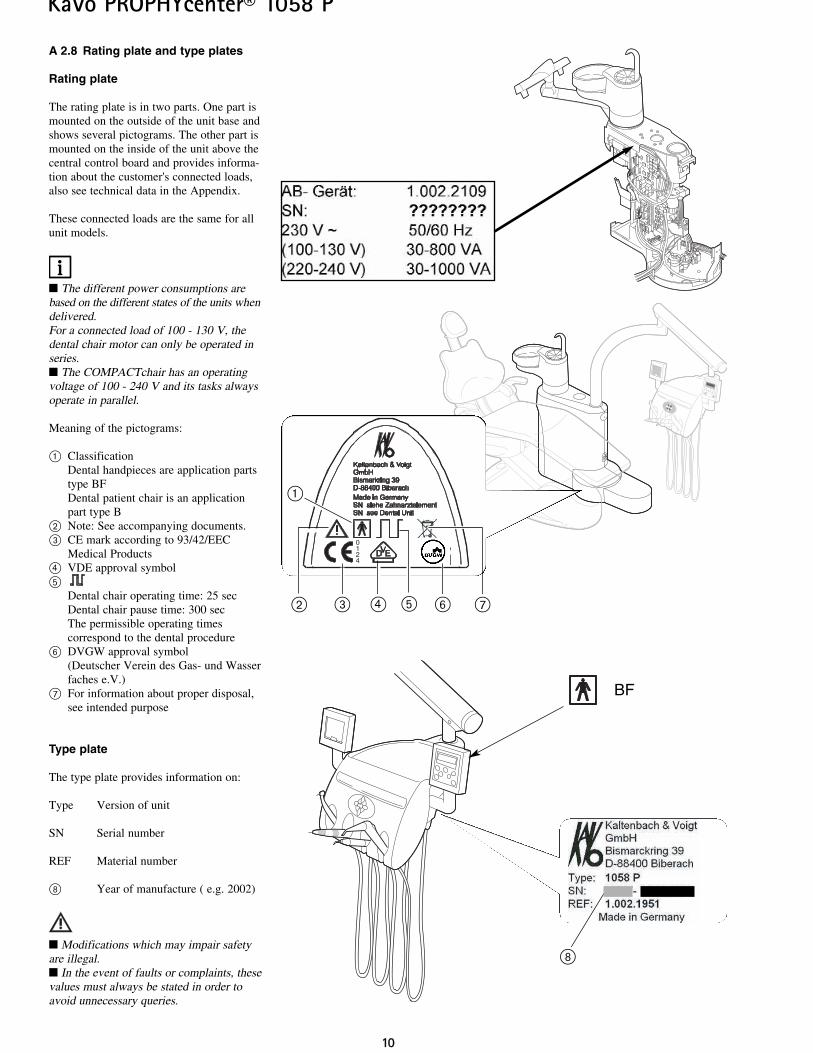
A 2.8 Rating plate and type plates
Rating plate
The rating plate is in two parts. One part ismounted on the outside of the unit base andshows several pictograms. The other part ismounted on the inside of the unit above thecentral control board and provides informa-tion about the customer's connected loads,also see technical data in the Appendix.
These connected loads are the same for allunit models.
The different power consumptions arebased on the different states of the units whendelivered.For a connected load of 100 - 130 V, thedental chair motor can only be operated inseries. The COMPACTchair has an operatingvoltage of 100 - 240 V and its tasks alwaysoperate in parallel.
Meaning of the pictograms:
@ ClassificationDental handpieces are application partstype BFDental patient chair is an applicationpart type B
” Note: See accompanying documents.# CE mark according to 93/42/EEC
Medical Products£ VDE approval symbolfi
Dental chair operating time: 25 secDental chair pause time: 300 secThe permissible operating times correspond to the dental procedure
Ì DVGW approval symbol(Deutscher Verein des Gas- und Wasserfaches e.V.)
\ For information about proper disposal,see intended purpose
Type plate
The type plate provides information on:
Type Version of unit
SN Serial number
REF Material number
| Year of manufacture ( e.g. 2002)
Modifications which may impair safetyare illegal. In the event of faults or complaints, thesevalues must always be stated in order toavoid unnecessary queries.
|
BF
0124
# £ fi” Ì
@
\
KaVo PROPHYcenter® 1058 P
11
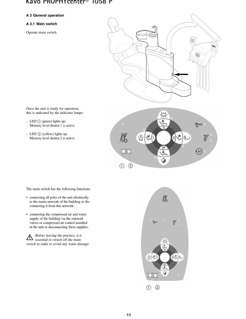
A 3 General operation
A 3.1 Main switch
Operate main switch.
Once the unit is ready for operation,this is indicated by the indicator lamps:
- LED @ (green) lights up:Memory level dentist 1 is active.
- LED ” (yellow) lights up:Memory level dentist 2 is active.
The main switch has the following functions:
• connecting all poles of the unit electricallyto the mains network of the building or dis-connecting it from this network.
• connecting the compressed air and watersupply of the building via the solenoidvalves or compressed air control installedin the unit or disconnecting these supplies.
Before leaving the practice, it isessential to switch off the main
switch in order to avoid any water damage.
@ ”
@ ”
1122
KaVo PROPHYcenter® 1058 P
@
”
#
£
fi
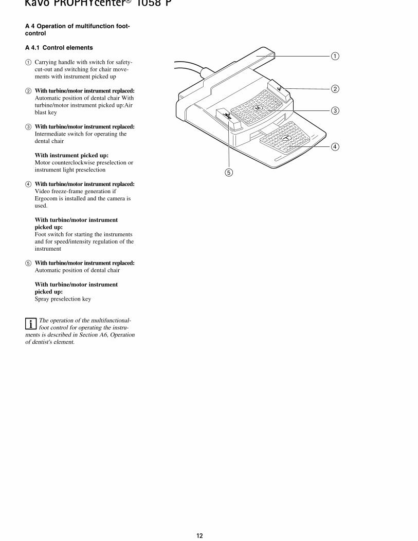
A 4 Operation of multifunction foot-control
A 4.1 Control elements
@ Carrying handle with switch for safety-cut-out and switching for chair move-ments with instrument picked up
” With turbine/motor instrument replaced:Automatic position of dental chair Withturbine/motor instrument picked up:Airblast key
# With turbine/motor instrument replaced:Intermediate switch for operating thedental chair
With instrument picked up:Motor counterclockwise preselection orinstrument light preselection
£ With turbine/motor instrument replaced:Video freeze-frame generation ifErgocom is installed and the camera isused.
With turbine/motor instrumentpicked up:Foot switch for starting the instrumentsand for speed/intensity regulation of theinstrument
fi With turbine/motor instrument replaced:Automatic position of dental chair
With turbine/motor instrumentpicked up:Spray preselection key
The operation of the multifunctional-foot control for operating the instru-
ments is described in Section A6, Operationof dentist's element.
1133
KaVo PROPHYcenter® 1058 P
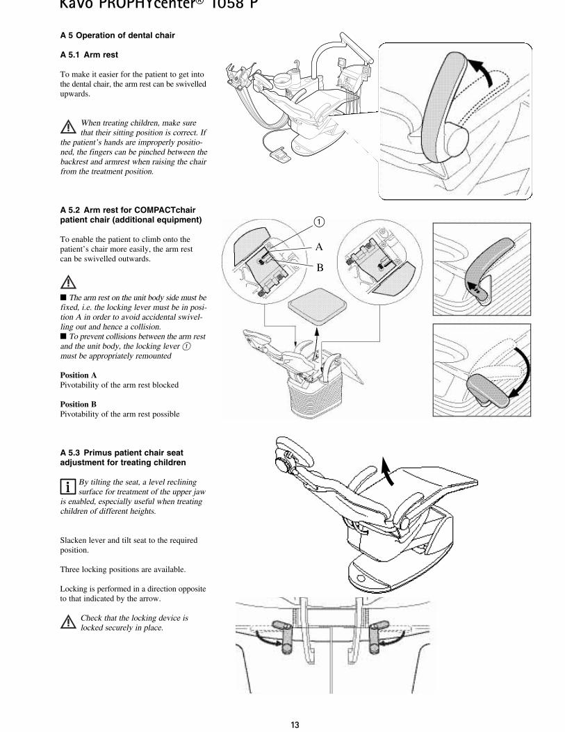
A 5 Operation of dental chair
A 5.1 Arm rest
To make it easier for the patient to get intothe dental chair, the arm rest can be swivelledupwards.
When treating children, make surethat their sitting position is correct. If
the patient’s hands are improperly positio-ned, the fingers can be pinched between thebackrest and armrest when raising the chairfrom the treatment position.
A 5.2 Arm rest for COMPACTchairpatient chair (additional equipment)
To enable the patient to climb onto thepatient’s chair more easily, the arm rest can be swivelled outwards.
The arm rest on the unit body side must befixed, i.e. the locking lever must be in posi-tion A in order to avoid accidental swivel-ling out and hence a collision. To prevent collisions between the arm restand the unit body, the locking lever @must be appropriately remounted
Position APivotability of the arm rest blocked
Position BPivotability of the arm rest possible
A 5.3 Primus patient chair seatadjustment for treating children
By tilting the seat, a level recliningsurface for treatment of the upper jaw
is enabled, especially useful when treatingchildren of different heights.
Slacken lever and tilt seat to the requiredposition.
Three locking positions are available.
Locking is performed in a direction oppositeto that indicated by the arrow.
Check that the locking device islocked securely in place.
A
B
@
1144
KaVo PROPHYcenter® 1058 P
@
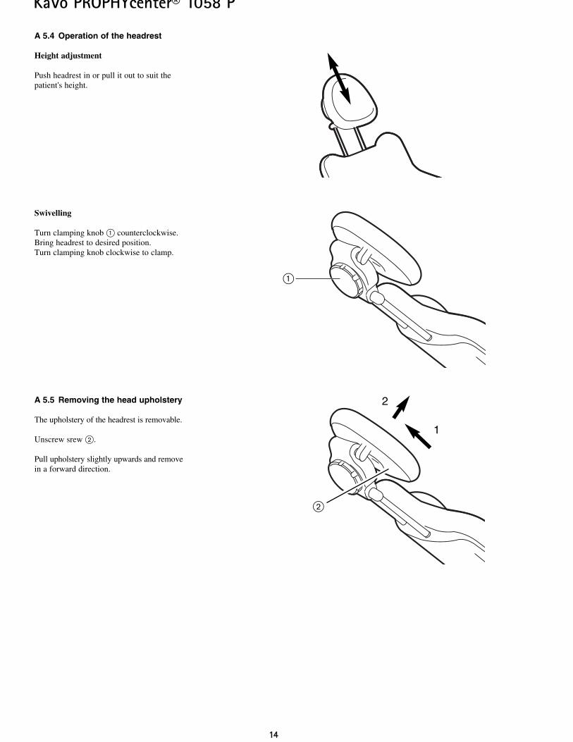
A 5.4 Operation of the headrest
Height adjustment
Push headrest in or pull it out to suit thepatient's height.
Swivelling
Turn clamping knob @ counterclockwise.Bring headrest to desired position.Turn clamping knob clockwise to clamp.
A 5.5 Removing the head upholstery
The upholstery of the headrest is removable.
Unscrew srew ”.
Pull upholstery slightly upwards and removein a forward direction.
1
2
”
1155
KaVo PROPHYcenter® 1058 P
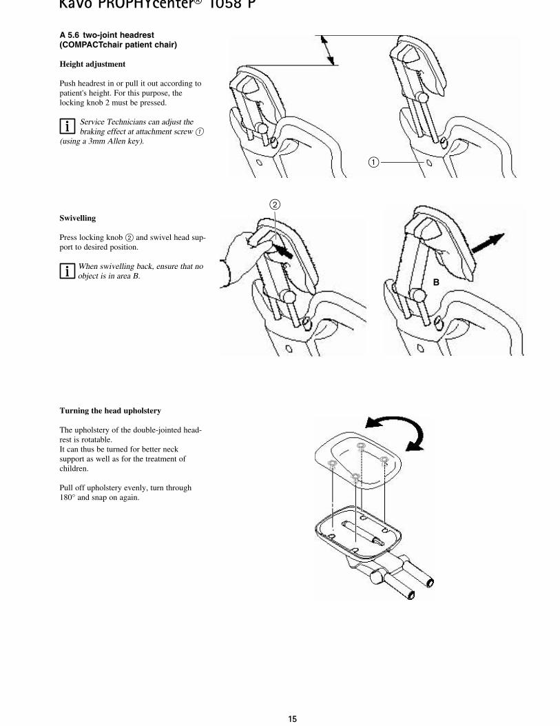
A 5.6 two-joint headrest(COMPACTchair patient chair)
Height adjustment
Push headrest in or pull it out according topatient's height. For this purpose, thelocking knob 2 must be pressed.
Service Technicians can adjust thebraking effect at attachment screw @
(using a 3mm Allen key).
Swivelling
Press locking knob ” and swivel head sup-port to desired position.
When swivelling back, ensure that noobject is in area B.
Turning the head upholstery
The upholstery of the double-jointed head-rest is rotatable.It can thus be turned for better neck support as well as for the treatment ofchildren.
Pull off upholstery evenly, turn through180° and snap on again.
B
@
”
1166
KaVo PROPHYcenter® 1058 P
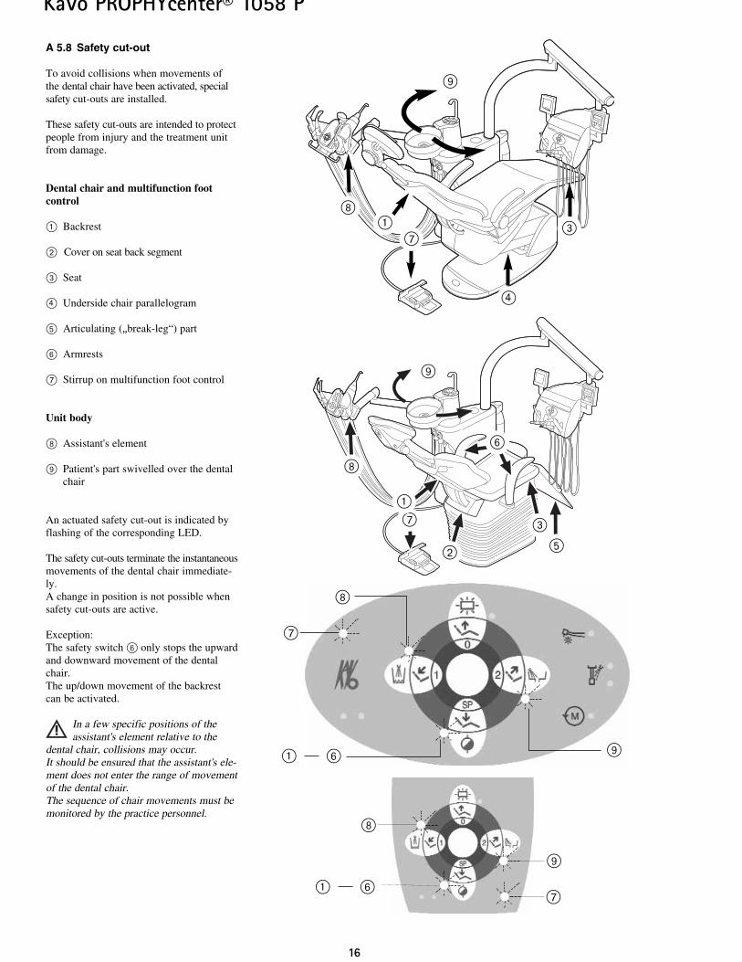
A 5.8 Safety cut-out
To avoid collisions when movements ofthe dental chair have been activated, specialsafety cut-outs are installed.
These safety cut-outs are intended to protectpeople from injury and the treatment unitfrom damage.
Dental chair and multifunction footcontrol
@ Backrest
” Cover on seat back segment
# Seat
£ Underside chair parallelogram
fi Articulating („break-leg“) part
Ì Armrests
\ Stirrup on multifunction foot control
Unit body
| Assistant's element
· Patient's part swivelled over the dentalchair
An actuated safety cut-out is indicated byflashing of the corresponding LED.
The safety cut-outs terminate the instantaneousmovements of the dental chair immediate-ly.A change in position is not possible whensafety cut-outs are active.
Exception:The safety switch Ì only stops the upwardand downward movement of the dentalchair.The up/down movement of the backrestcan be activated.
In a few specific positions of theassistant's element relative to the
dental chair, collisions may occur.It should be ensured that the assistant's ele-ment does not enter the range of movementof the dental chair.The sequence of chair movements must bemonitored by the practice personnel.
@ #\
|
·
£
·
|
\
·
|
@ Ì\
|
·
fi
#\@
Ì
”
@ Ì
1177
KaVo PROPHYcenter® 1058 P
A 5.9 Motor support (optional) forCOMPACTchair headrest/patient part
The movement sequences of themotor assistance are set at the
factory. During commissioning or repairs,these settings should be checked with theaid of the following descriptions and ifnecessary adjusted.
Operation of the patient’s component
The position of the patient’s component issaved together with the chair position.
Two memory positions are available:
1. Storing with SP
The patient’s component swivels to therinse position after the end of the chairmovement.
2. Storing with AP0 or AP1 or AP2
The patient's component swivels to the restposition before the sequence for the auto-matic position.
Storage:Set chair position.Swivel patient's component to desired position.
Press AP key on which the position is to bestored until a signal is heard.
The patient’s component can also beswivelled manually.
1188
KaVo PROPHYcenter® 1058 P
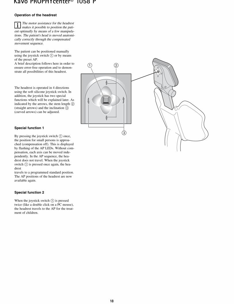
Operation of the headrest
The motor assistance for the headrestmakes it possible to position the pati-
ent optimally by means of a few manipula-tions. The patient's head is moved anatomi-cally correctly through the compensatedmovement sequence.
The patient can be positioned manuallyusing the joystick switch @ or by meansof the preset AP.A brief description follows here in order toensure error-free operation and to demon-strate all possibilities of this headrest.
The headrest is operated in 4 directionsusing the soft silicone joystick switch. Inaddition, the joystick has two special functions which will be explained later. Asindicated by the arrows, the stem length ”(straight arrows) and the inclination #(curved arrows) can be adjusted.
Special function 1
By pressing the joystick switch @ once,the position for small persons is approa-ched (compensation off). This is displayedby flashing of the AP LEDs. Without com-pensation, each axis can be moved inde-pendently. In the AP sequence, the hea-drest does not travel. When the joystickswitch @ is pressed once again, the hea-drest travels to a programmed standard position.The AP positions of the headrest are nowavailable again.
Special function 2
When the joystick switch @ is pressedtwice (like a double click on a PC mouse),the headrest travels to the AP for the treat-ment of children.
#
”@
1199
KaVo PROPHYcenter® 1058 P
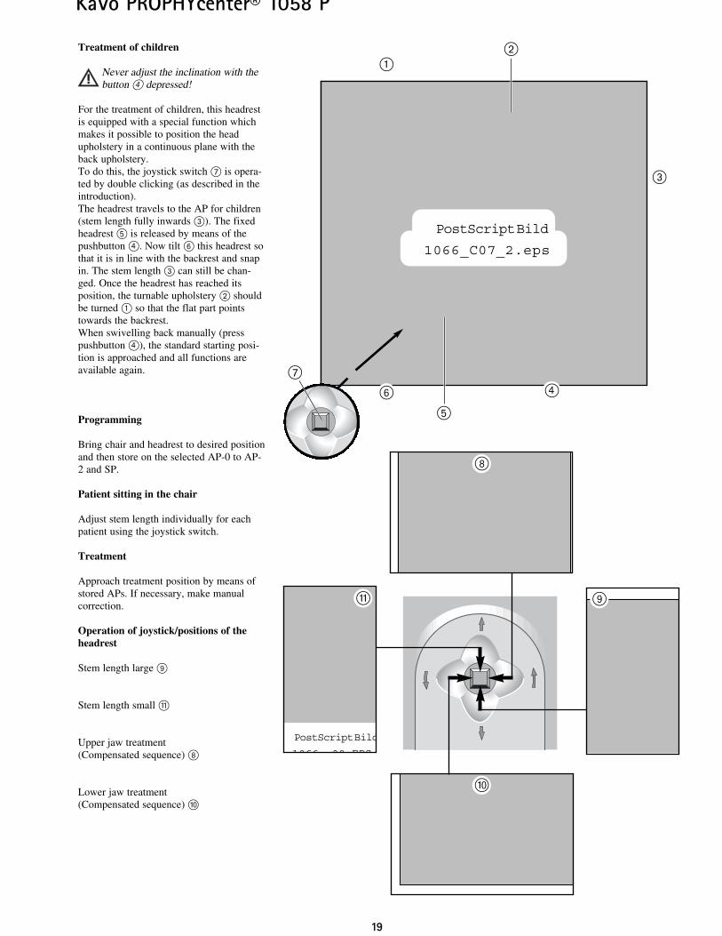
Treatment of children
Never adjust the inclination with thebutton £ depressed!
For the treatment of children, this headrestis equipped with a special function whichmakes it possible to position the headupholstery in a continuous plane with theback upholstery.To do this, the joystick switch \ is opera-ted by double clicking (as described in theintroduction).The headrest travels to the AP for children(stem length fully inwards #). The fixedheadrest fi is released by means of thepushbutton £. Now tilt Ì this headrest sothat it is in line with the backrest and snapin. The stem length # can still be chan-ged. Once the headrest has reached itsposition, the turnable upholstery ” shouldbe turned @ so that the flat part pointstowards the backrest.When swivelling back manually (press pushbutton £), the standard starting posi-tion is approached and all functions areavailable again.
Programming
Bring chair and headrest to desired positionand then store on the selected AP-0 to AP-2 and SP.
Patient sitting in the chair
Adjust stem length individually for eachpatient using the joystick switch.
Treatment
Approach treatment position by means ofstored APs. If necessary, make manual correction.
Operation of joystick/positions of theheadrest
Stem length large ·
Stem length small »
Upper jaw treatment(Compensated sequence) |
Lower jaw treatment(Compensated sequence) ¯
PostScript Bild
1066 09 EPS
|
·»
¯
PostScript Bild
1066_C07_2.eps
@
#
£Ì
fi
”
\
2200
KaVo PROPHYcenter® 1058 P
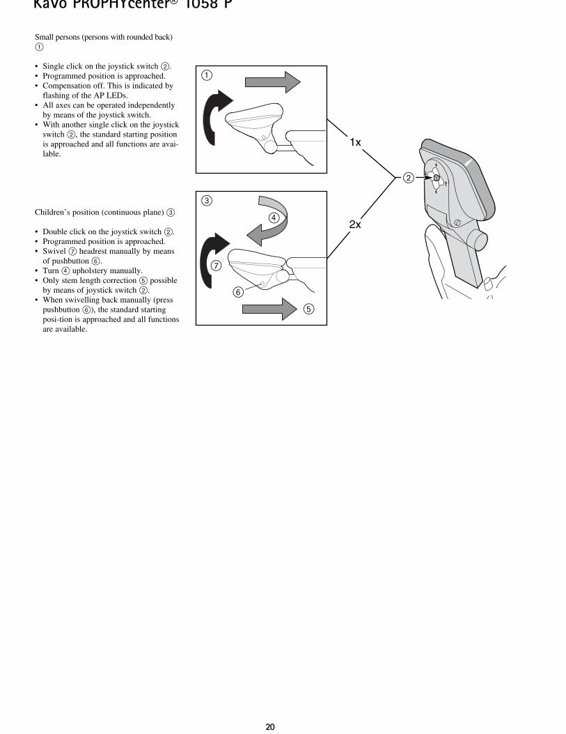
Small persons (persons with rounded back)@
• Single click on the joystick switch ”.• Programmed position is approached.• Compensation off. This is indicated by
flashing of the AP LEDs.• All axes can be operated independently
by means of the joystick switch.• With another single click on the joystick
switch ”, the standard starting positionis approached and all functions are avai-lable.
Children’s position (continuous plane) #
• Double click on the joystick switch ”.• Programmed position is approached.• Swivel \ headrest manually by means
of pushbutton Ì.• Turn £ upholstery manually.• Only stem length correction fi possible
by means of joystick switch ”.• When swivelling back manually (press
pushbutton Ì), the standard startingposi-tion is approached and all functionsare available.
”
@
#
fi
\
£
1x
2x
Ì
2211
KaVo PROPHYcenter® 1058 P
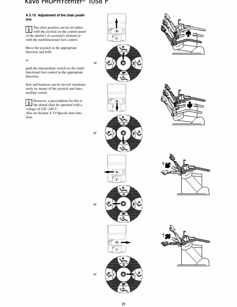
A 5.10 Adjustment of the chair positi-ons
The chair position can be set either-with the joystick on the control panel
of the dentist's or assistant's element orwith the multifunctional foot control.
Move the joystick in the appropriatedirection and hold
or
push the intermediate switch on the multi-functional foot control in the appropriatedirection.
Seat and backrest can be moved simultane-ously by means of the joystick and inter-mediate switch.
However, a precondition for this isthe dental chair be operated with a
voltage of 220 -240 V.Also see Section A 5.9 Special chair func-tions
T
M
T
M
T
M
T
M
or
or
or
or
2222
KaVo PROPHYcenter® 1058 P
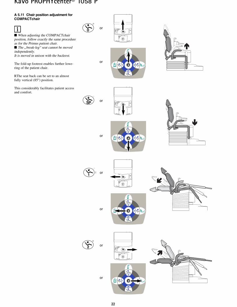
A 5.11 Chair position adjustment forCOMPACTchair
When adjusting the COMPACTchairposition, follow exactly the same procedureas for the Primus patient chair. The „break-leg“ seat cannot be movedindependently.It is moved in unison with the backrest.
The fold-up footrest enables further lowe-ring of the patient chair.
RThe seat back can be set to an almostfully vertical (85°) position.
This considerably facilitates patient accessand comfort.
T
Mor
T
Mor
T
M
or
T
M
or
or
or
or
or
2233
KaVo PROPHYcenter® 1058 P
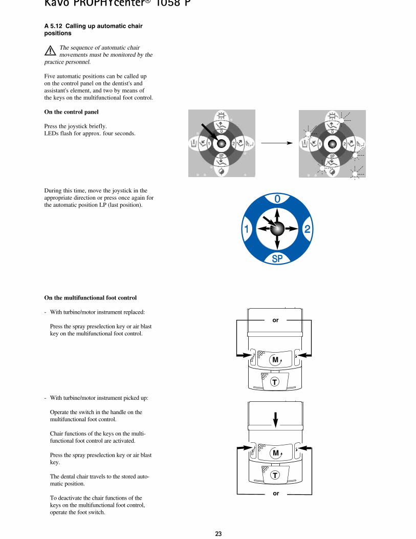
A 5.12 Calling up automatic chairpositions
The sequence of automatic chairmovements must be monitored by the
practice personnel.
Five automatic positions can be called upon the control panel on the dentist's andassistant's element, and two by means ofthe keys on the multifunctional foot control.
On the control panel
Press the joystick briefly.LEDs flash for approx. four seconds.
During this time, move the joystick in theappropriate direction or press once again forthe automatic position LP (last position).
On the multifunctional foot control
- With turbine/motor instrument replaced:
Press the spray preselection key or air blastkey on the multifunctional foot control.
- With turbine/motor instrument picked up:
Operate the switch in the handle on themultifunctional foot control.
Chair functions of the keys on the multi-functional foot control are activated.
Press the spray preselection key or air blastkey.
The dental chair travels to the stored auto-matic position.
To deactivate the chair functions of thekeys on the multifunctional foot control,operate the foot switch.
T
M
or
T
M
or
2244
KaVo PROPHYcenter® 1058 P
T
M
T
M
+
or
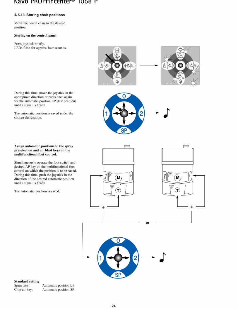
A 5.13 Storing chair positions
Move the dental chair to the desired position.
Storing on the control panel
Press joystick briefly.LEDs flash for approx. four seconds.
During this time, move the joystick in theappropriate direction or press once againfor the automatic position LP (last position)until a signal is heard.
The automatic position is saved under thechosen designation.
Assign automatic positions to the spraypreselection and air blast keys on themultifunctional foot control.
Simultaneously operate the foot switch and-desired AP key on the multifunctional footcontrol on which the position is to be saved.During this time, push the joystick in thedirection of the desired automatic positionuntil a signal is heard.
The automatic position is saved.
Standard settingSpray key: Automatic position LPChip air key: Automatic position SP
+
2255
KaVo PROPHYcenter® 1058 P
A 5.14 Special chair functions
At an operating voltage above 200 V, thespindle motors can be operated in parallel,i.e. chair movement and backrest movementoccur simultaneously in the automatic pro-gram.
At an operating voltage below 200 V, themovements in the automatic program musttake place in succession owing to the powerconsumptions.The conversion is performed by a serviceengineer.
The COMPACTchair has an operatingvoltage of 100 - 240 V and its tasks alwaysoperate in parallel.
The lifting motor and backrest motorare provided with thermal fuses.
The motors are switched off at an operating temperature of 140 °C.Depending on the ambient temperature, thecooling phase takes about 15 minutes.After the end of the cooling phase, the lift-ing motor and backrest motor are ready foroperation again.In customary operation in the practice, suchtemperatures are not reached.In demonstrations and exhibitions, the cut-out temperature may be reached in the eventof frequent operation, particularly in thecase of the lifting movement (about 8 com-plete movement sequences).
2266
KaVo PROPHYcenter® 1058 P
T
M
+
E123
A 6 Dentist's element
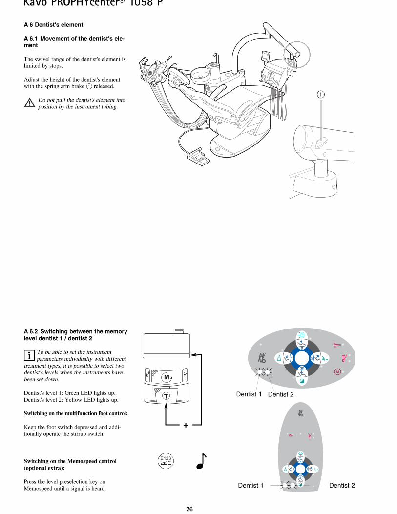
A 6.1 Movement of the dentist's ele-ment
The swivel range of the dentist's element islimited by stops.
Adjust the height of the dentist's elementwith the spring arm brake @ released.
Do not pull the dentist's element intoposition by the instrument tubing.
A 6.2 Switching between the memorylevel dentist 1 / dentist 2
To be able to set the instrumentparameters individually with different
treatment types, it is possible to select twodentist's levels when the instruments havebeen set down.
Dentist's level 1: Green LED lights up.Dentist's level 2: Yellow LED lights up.
Switching on the multifunction foot control:
Keep the foot switch depressed and addi-tionally operate the stirrup switch.
Switching on the Memospeed control(optional extra):
Press the level preselection key onMemospeed until a signal is heard.
Dentist 2Dentist 1
Dentist 1 Dentist 2
@
2277
KaVo PROPHYcenter® 1058 P
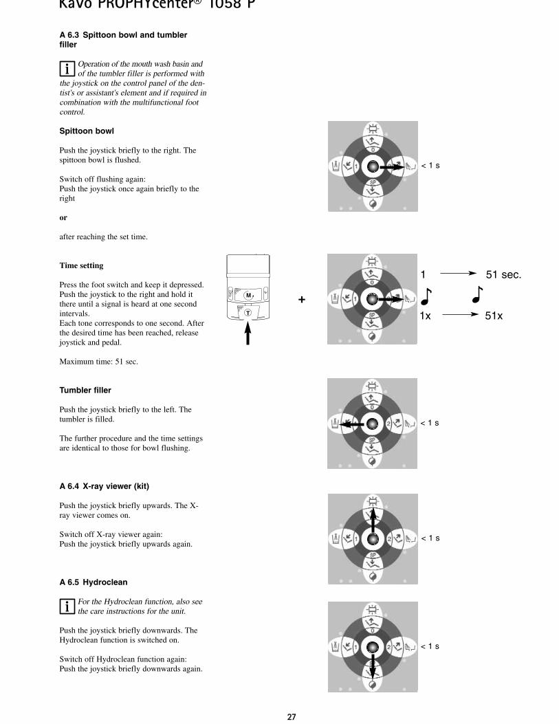
A 6.3 Spittoon bowl and tumblerfiller
Operation of the mouth wash basin andof the tumbler filler is performed with
the joystick on the control panel of the den-tist's or assistant's element and if required incombination with the multifunctional footcontrol.
Spittoon bowl
Push the joystick briefly to the right. Thespittoon bowl is flushed.
Switch off flushing again:Push the joystick once again briefly to theright
or
after reaching the set time.
Time setting
Press the foot switch and keep it depressed.Push the joystick to the right and hold itthere until a signal is heard at one secondintervals.Each tone corresponds to one second. Afterthe desired time has been reached, releasejoystick and pedal.
Maximum time: 51 sec.
Tumbler filler
Push the joystick briefly to the left. Thetumbler is filled.
The further procedure and the time settingsare identical to those for bowl flushing.
A 6.4 X-ray viewer (kit)
Push the joystick briefly upwards. The X-ray viewer comes on.
Switch off X-ray viewer again:Push the joystick briefly upwards again.
A 6.5 Hydroclean
For the Hydroclean function, also seethe care instructions for the unit.
Push the joystick briefly downwards. TheHydroclean function is switched on.
Switch off Hydroclean function again:Push the joystick briefly downwards again.
1 51 sec.
1x 51x
< 1 s
T
M
< 1 s
+
< 1 s
< 1 s

2288
KaVo PROPHYcenter® 1058 P
A 6.6 Priority circuit
All instruments, except for three-function-handpiece, on the dentist's element are pro-tected from simultaneous use by a prioritylogic circuit.
Only the instrument first removed is readyfor operation.All instruments subsequently removed can-not be activated.
On these instruments, it is now possible tochange e.g. bur or PIEZOlux tips.
2299
KaVo PROPHYcenter® 1058 P
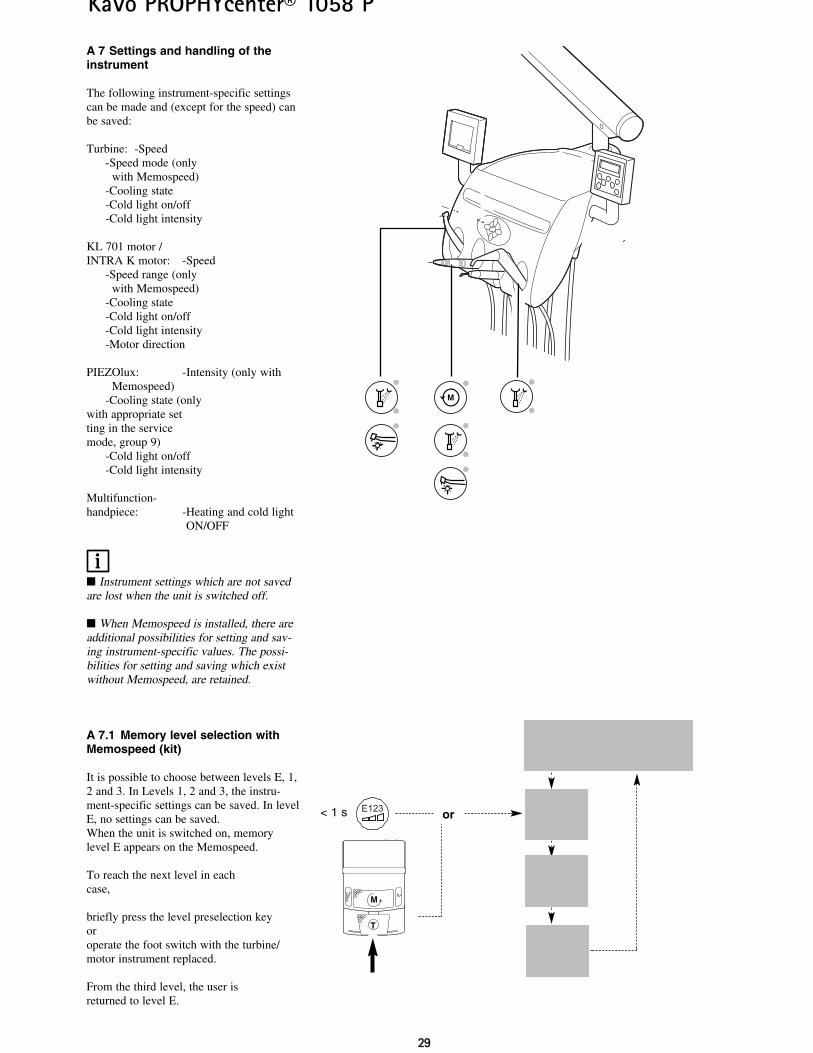
A 7 Settings and handling of theinstrument
The following instrument-specific settingscan be made and (except for the speed) canbe saved:
Turbine: -Speed-Speed mode (only
with Memospeed)-Cooling state-Cold light on/off-Cold light intensity
KL 701 motor /INTRA K motor: -Speed
-Speed range (onlywith Memospeed)
-Cooling state-Cold light on/off-Cold light intensity-Motor direction
PIEZOlux: -Intensity (only withMemospeed)
-Cooling state (only with appropriate setting in the service mode, group 9)
-Cold light on/off-Cold light intensity
Multifunction- handpiece: -Heating and cold light
ON/OFF
Instrument settings which are not savedare lost when the unit is switched off.
When Memospeed is installed, there areadditional possibilities for setting and sav-ing instrument-specific values. The possi-bilities for setting and saving which existwithout Memospeed, are retained.
A 7.1 Memory level selection withMemospeed (kit)
It is possible to choose between levels E, 1,2 and 3. In Levels 1, 2 and 3, the instru-ment-specific settings can be saved. In levelE, no settings can be saved.When the unit is switched on, memorylevel E appears on the Memospeed.
To reach the next level in eachcase,
briefly press the level preselection keyoroperate the foot switch with the turbine/motor instrument replaced.
From the third level, the user isreturned to level E.
T
M
E123 or< 1 s
3300
KaVo PROPHYcenter® 1058 P
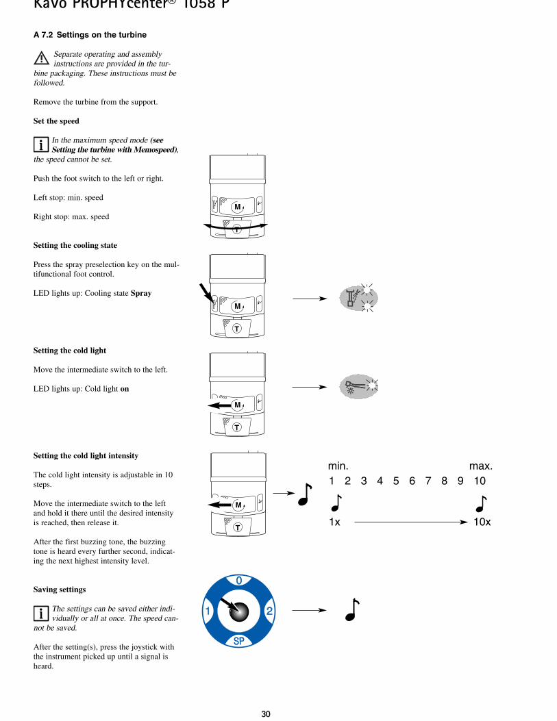
A 7.2 Settings on the turbine
Separate operating and assemblyinstructions are provided in the tur-
bine packaging. These instructions must befollowed.
Remove the turbine from the support.
Set the speed
In the maximum speed mode (seeSetting the turbine with Memospeed),
the speed cannot be set.
Push the foot switch to the left or right.
Left stop: min. speed
Right stop: max. speed
Setting the cooling state
Press the spray preselection key on the mul-tifunctional foot control.
LED lights up: Cooling state Spray
Setting the cold light
Move the intermediate switch to the left.
LED lights up: Cold light on
Setting the cold light intensity
The cold light intensity is adjustable in 10steps.
Move the intermediate switch to the leftand hold it there until the desired intensityis reached, then release it.
After the first buzzing tone, the buzzingtone is heard every further second, indicat-ing the next highest intensity level.
Saving settings
The settings can be saved either indi-vidually or all at once. The speed can-
not be saved.
After the setting(s), press the joystick withthe instrument picked up until a signal isheard.
T
M
T
M
T
M
T
M
1 2 3 4 5 6 7 8 9 10
1x 10x
min. max.
3311
KaVo PROPHYcenter® 1058 P
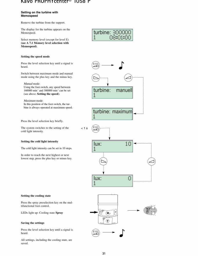
Setting on the turbine withMemospeed
Remove the turbine from the support.
The display for the turbine appears on theMemospeed.
Select memory level (except for level E)(see A 7.1 Memory level selection withMemospeed).
Setting the speed mode
Press the level selection key until a signal isheard.
Switch between maximum mode and manualmode using the plus key and the minus key.
Manual mode:Using the foot switch, any speed between160000 min-1 and 300000 min-1 can be set(see above: Setting the speed).
Maximum mode:In this position of the foot switch, the tur-bine is always operated at maximum speed.
Press the level selection key briefly.
The system switches to the setting of thecold light intensity.
Setting the cold light intensity
The cold light intensity can be set in 10 steps.
In order to reach the next highest or nextlowest step, press the plus key or minus key.
Setting the cooling state
Press the spray preselection key on the mul-tifunctional foot control.
LEDs light up: Cooling state Spray
Saving the settings
Press the level selection key until a signal isheard.
All settings, including the cooling state, aresaved.
E123
turbine:
E123
turbine: manuell
turbine: maximum
lux:
lux:
E123
T
M
< 1 s
KaVo PROPHYcenter® 1058 P
T
M
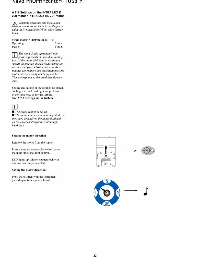
A 7.3 Settings on the INTRA LUX K200 motor / INTRA LUX KL 701 motor
Separate operating and installationinstructions are included in the pack-
aging. It is essential to follow these instruc-tions.
Mode motor K 200/motor KL 701Operating 2 min.Pause 5 min.
The mode 2 min operation/5 minpause represents the possible limiting
load of the motor (full load at maximumspeed). In practice, pulsed loads lasting forseconds and pauses lasting for seconds tominutes are realistic, the maximum possiblemotor current usually not being reached.This corresponds to the usual dental proce-dure.
Setting and saving of the settings for speed,cooling state and cold light are performedin the same way as for the turbine (see A 7.2 Settings on the turbine).
The speed cannot be saved. The minimum or maximum magnitude ofthe speed depends on the motor used andon the attached straight or contra-anglehandpiece.
Setting the motor direction
Remove the motor from the support.
Press the motor counterclockwise key onthe multifunctional foot control.
LED lights up: Motor counterclockwiserotation has bee preselected.
Saving the motor direction
Press the joystick with the instrumentpicked up until a signal is heard.
3322
3333
KaVo PROPHYcenter® 1058 P
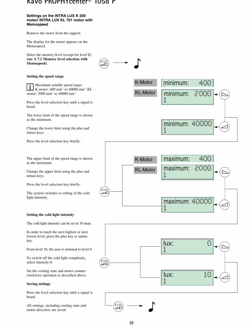
Settings on the INTRA LUX K 200motor/ INTRA LUX KL 701 motor withMemospeed
Remove the motor from the support.
The display for the motor appears on theMemospeed.
Select the memory level (except for level E)(see A 7.1 Memory level selection withMemospeed).
Setting the speed range
Maximum settable speed range:K motor: 400 min-1 to 40000 min-1 KL
motor: 2000 min-1 to 40000 min-1
Press the level selection key until a signal isheard.
The lower limit of the speed range is shownas the minimum.
Change the lower limit using the plus andminus keys.
Press the level selection key briefly.
The upper limit of the speed range is shownas the maximum.
Change the upper limit using the plus andminus keys.
Press the level selection key briefly.
The system switches to setting of the coldlight intensity.
Setting the cold light intensity
The cold light intensity can be set in 10 steps.
In order to reach the next highest or nextlowest level, press the plus key or minuskey.
From level 10, the user is returned to level 0.
To switch off the cold light completely,select intensity 0.
Set the cooling state and motor counter-clockwise operation as described above.
Saving settings
Press the level selection key until a signal isheard.
All settings, including cooling state andmotor direction, are saved.
E123
E123
KL-Motor minimum:
minimum:K-Motor
minimum:
maximum:
maximum:
KL-Motor
K-Motor
maximum:
lux:
lux:
E123
E123
3344
KaVo PROPHYcenter® 1058 P
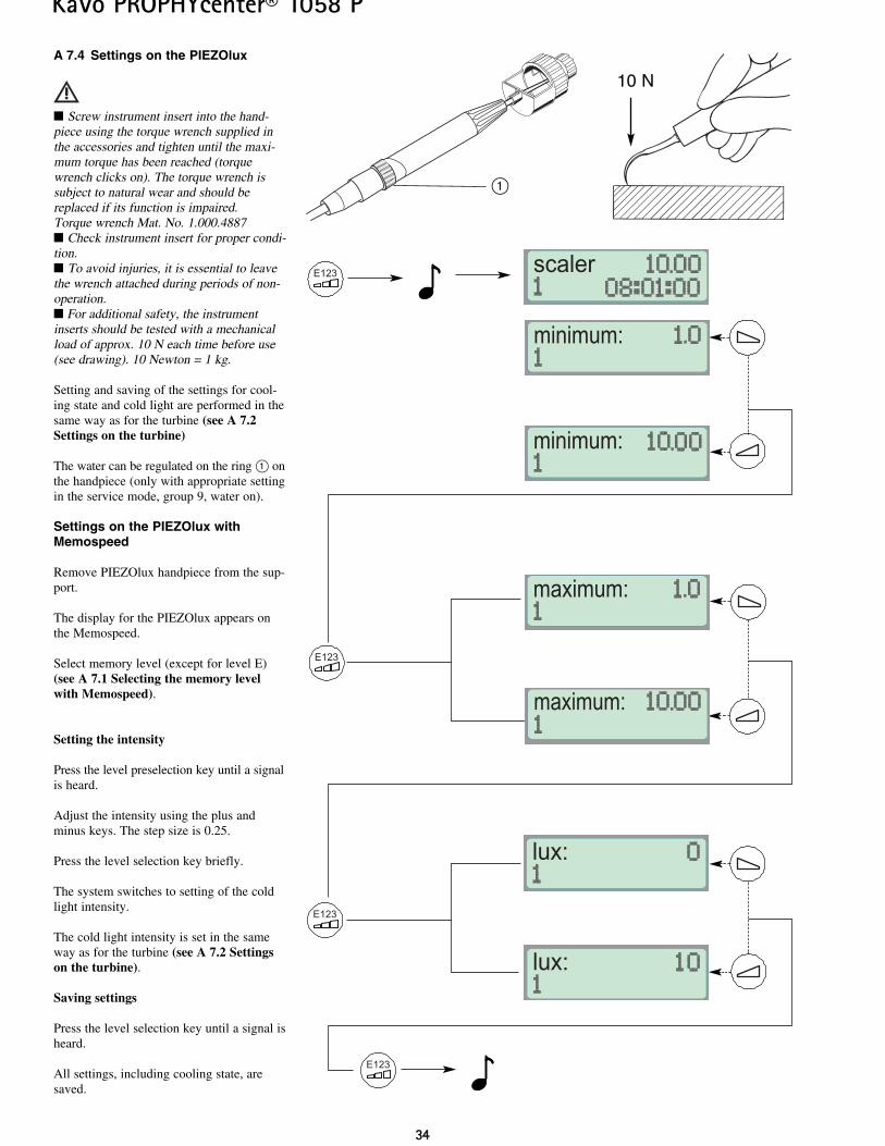
A 7.4 Settings on the PIEZOlux
Screw instrument insert into the hand-piece using the torque wrench supplied inthe accessories and tighten until the maxi-mum torque has been reached (torquewrench clicks on). The torque wrench issubject to natural wear and should bereplaced if its function is impaired.Torque wrench Mat. No. 1.000.4887 Check instrument insert for proper condi-tion. To avoid injuries, it is essential to leavethe wrench attached during periods of non-operation. For additional safety, the instrumentinserts should be tested with a mechanicalload of approx. 10 N each time before use(see drawing). 10 Newton = 1 kg.
Setting and saving of the settings for cool-ing state and cold light are performed in thesame way as for the turbine (see A 7.2Settings on the turbine)
The water can be regulated on the ring @ onthe handpiece (only with appropriate settingin the service mode, group 9, water on).
Settings on the PIEZOlux withMemospeed
Remove PIEZOlux handpiece from the sup-port.
The display for the PIEZOlux appears onthe Memospeed.
Select memory level (except for level E)(see A 7.1 Selecting the memory levelwith Memospeed).
Setting the intensity
Press the level preselection key until a signalis heard.
Adjust the intensity using the plus andminus keys. The step size is 0.25.
Press the level selection key briefly.
The system switches to setting of the coldlight intensity.
The cold light intensity is set in the sameway as for the turbine (see A 7.2 Settingson the turbine).
Saving settings
Press the level selection key until a signal isheard.
All settings, including cooling state, aresaved.
E123
E123
minimum:
minimum:
maximum:
maximum:
lux:
lux:
scalerE123
E123
@
10 N
3355
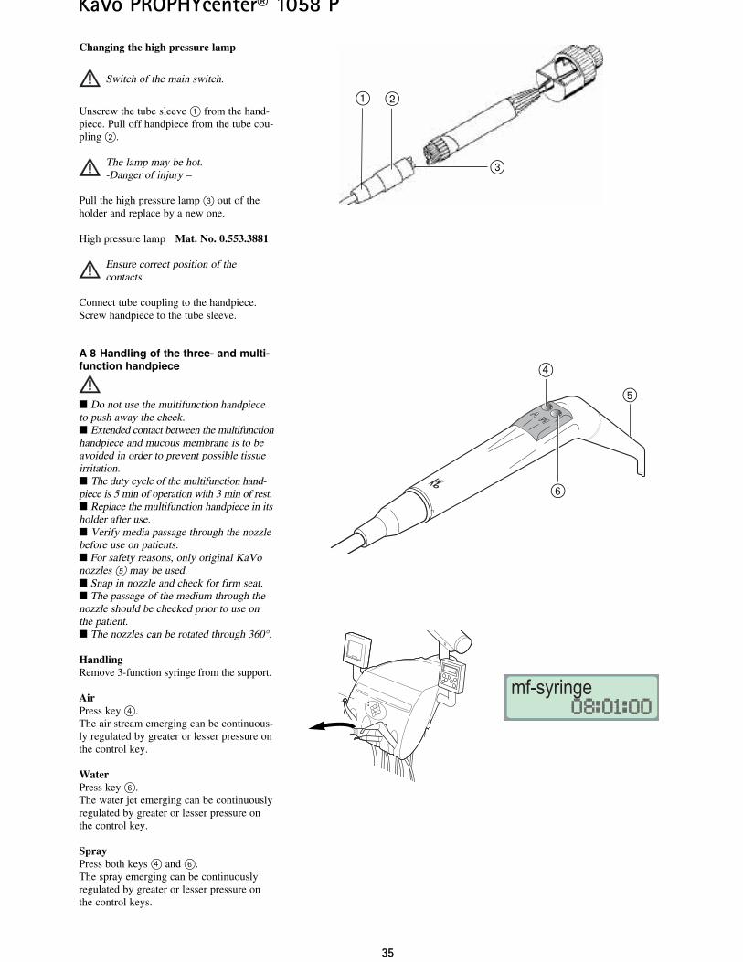
Changing the high pressure lamp
Switch of the main switch.
Unscrew the tube sleeve @ from the hand-piece. Pull off handpiece from the tube cou-pling ”.
The lamp may be hot.-Danger of injury –
Pull the high pressure lamp # out of theholder and replace by a new one.
High pressure lamp Mat. No. 0.553.3881
Ensure correct position of the contacts.
Connect tube coupling to the handpiece.Screw handpiece to the tube sleeve.
A 8 Handling of the three- and multi-function handpiece
Do not use the multifunction handpieceto push away the cheek. Extended contact between the multifunctionhandpiece and mucous membrane is to beavoided in order to prevent possible tissueirritation. The duty cycle of the multifunction hand-piece is 5 min of operation with 3 min of rest. Replace the multifunction handpiece in itsholder after use. Verify media passage through the nozzlebefore use on patients. For safety reasons, only original KaVonozzles fi may be used. Snap in nozzle and check for firm seat. The passage of the medium through thenozzle should be checked prior to use onthe patient. The nozzles can be rotated through 360°.
HandlingRemove 3-function syringe from the support.
AirPress key £. The air stream emerging can be continuous-ly regulated by greater or lesser pressure onthe control key.
WaterPress key Ì. The water jet emerging can be continuouslyregulated by greater or lesser pressure onthe control key.
SprayPress both keys £ and Ì. The spray emerging can be continuouslyregulated by greater or lesser pressure onthe control keys.
KaVo PROPHYcenter® 1058 P
#
”@
fi
£
Ì
mf-syringe
3366
KaVo PROPHYcenter® 1058 P
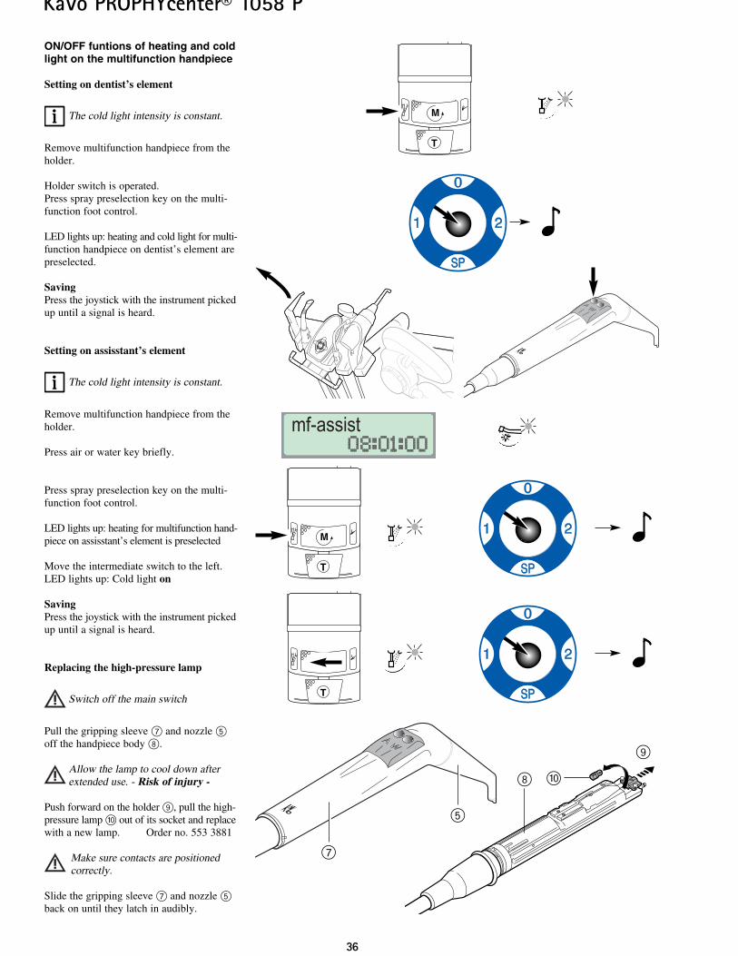
ON/OFF funtions of heating and coldlight on the multifunction handpiece
Setting on dentist’s element
The cold light intensity is constant.
Remove multifunction handpiece from theholder.
Holder switch is operated.Press spray preselection key on the multi-function foot control.
LED lights up: heating and cold light for multi-function handpiece on dentist’s element arepreselected.
SavingPress the joystick with the instrument pickedup until a signal is heard.
Setting on assisstant’s element
The cold light intensity is constant.
Remove multifunction handpiece from theholder.
Press air or water key briefly.
Press spray preselection key on the multi-function foot control.
LED lights up: heating for multifunction hand-piece on assisstant’s element is preselected
Move the intermediate switch to the left.LED lights up: Cold light on
SavingPress the joystick with the instrument pickedup until a signal is heard.
Replacing the high-pressure lamp
Switch off the main switch
Pull the gripping sleeve \ and nozzle fioff the handpiece body |.
Allow the lamp to cool down afterextended use. - Risk of injury -
Push forward on the holder ·, pull the high-pressure lamp ¯ out of its socket and replacewith a new lamp. Order no. 553 3881
Make sure contacts are positioned correctly.
Slide the gripping sleeve \ and nozzle fiback on until they latch in audibly.
¯
·
|
fi
\
mf-assist
T
M
T
M
T
M
3377
KaVo PROPHYcenter® 1058 P
A 9 Handling POLYlux II
For operation, see the POLYlux II operatinginstructions supplied separately.
A 10 Time settings and functionkeys on the Memospeed
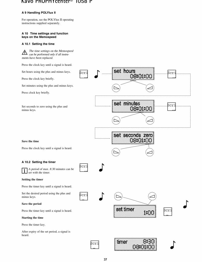
A 10.1 Setting the time
The time settings on the Memospeedcan be performed only if all instru-
ments have been replaced.
Press the clock key until a signal is heard.
Set hours using the plus and minus keys.
Press the clock key briefly.
Set minutes using the plus and minus keys.
Press clock key briefly.
Set seconds to zero using the plus andminus keys.
Save the time
Press the clock key until a signal is heard.
A 10.2 Setting the timer
A period of max. 8:30 minutes can beset with the timer.
Setting the timer
Press the timer key until a signal is heard.
Set the desired period using the plus andminus keys.
Save the period
Press the timer key until a signal is heard.
Starting the time
Press the timer key.
After expiry of the set period, a signal isheard.
Scri
e Uh
Scri
Tas
Scri
e Uh
Scri
e Uh
Scri
e Uh
Scri
Tas
Scri
Tas
3388
KaVo PROPHYcenter® 1058 P
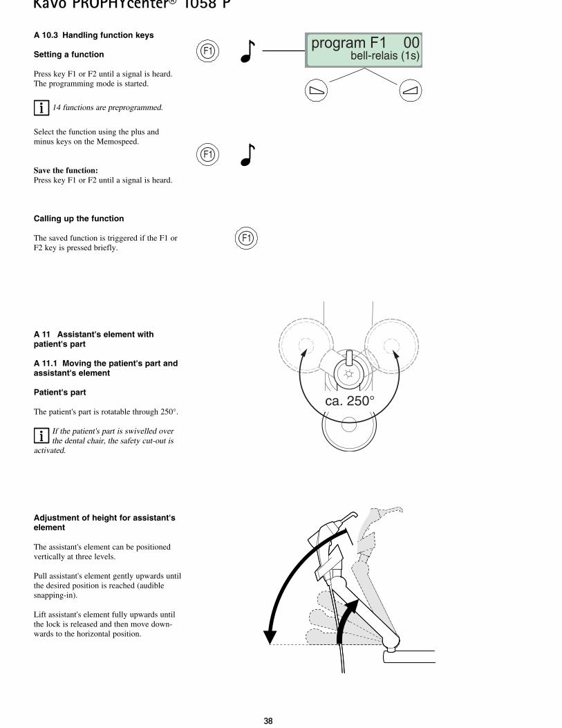
A 10.3 Handling function keys
Setting a function
Press key F1 or F2 until a signal is heard.The programming mode is started.
14 functions are preprogrammed.
Select the function using the plus andminus keys on the Memospeed.
Save the function:Press key F1 or F2 until a signal is heard.
Calling up the function
The saved function is triggered if the F1 orF2 key is pressed briefly.
A 11 Assistant's element withpatient's part
A 11.1 Moving the patient's part andassistant's element
Patient's part
The patient's part is rotatable through 250°.
If the patient's part is swivelled overthe dental chair, the safety cut-out is
activated.
Adjustment of height for assistant'selement
The assistant's element can be positionedvertically at three levels.
Pull assistant's element gently upwards untilthe desired position is reached (audiblesnapping-in).
Lift assistant's element fully upwards untilthe lock is released and then move down-wards to the horizontal position.
ca. 250°
F1program F1 00 bell-relais (1s)
F1
F1
3399
KaVo PROPHYcenter® 1058 P
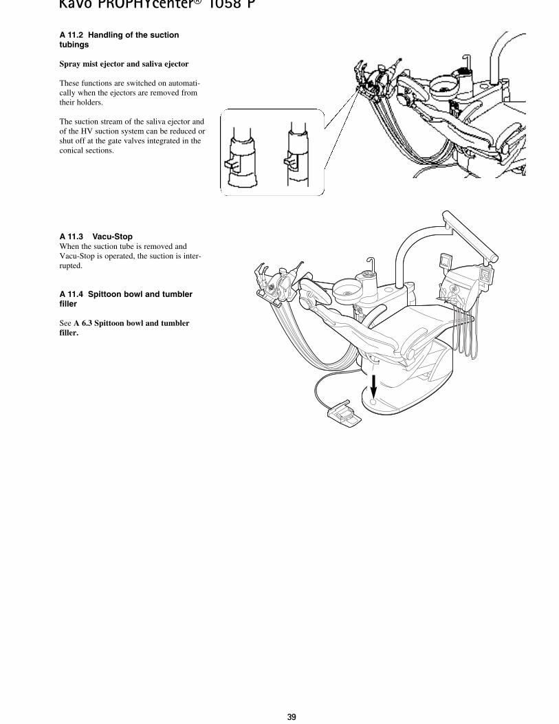
A 11.2 Handling of the suction tubings
Spray mist ejector and saliva ejector
These functions are switched on automati-cally when the ejectors are removed fromtheir holders.
The suction stream of the saliva ejector andof the HV suction system can be reduced orshut off at the gate valves integrated in theconical sections.
A 11.3 Vacu-StopWhen the suction tube is removed andVacu-Stop is operated, the suction is inter-rupted.
A 11.4 Spittoon bowl and tumblerfiller
See A 6.3 Spittoon bowl and tumblerfiller.
4400
KaVo PROPHYcenter® 1058 P
Rectification
Switch on main switch
Check main fuse and if necessary replaceMicrofuse T 6.3 H Mat. No. 0.223.2783The main fuse is located next to the mainswitch
Preselect cold light (see A 6.7)
Replace high-pressure lamp(see the instructions supplied with theinstruments)
Preselect spray (see A 6.7)
Open spray regulation ring
Open main tap
Switch on compressor
Replace turbine rotorFollow turbine instructions
Clean spray nozzles according to instrumentinstructions supplied
Replace O-rings
Replace all O-rings of the Multiflex cou-pling
Open slides
Clean filters
Release foot switch
Check fuse of the suction machine
Follow operating instructions of the amal-gam separator
Cause
Main switch off
Main fuse blown
Cold light not preselected
High-pressure lamp faulty
No spray preselected
Spray regulation on the instruments closed
Main tap in practice closed
Compressor not switched on
Turbine rotor faulty
Spray nozzles soiled or coated withlimescale
O-rings on Multiflex / motor coupling dam-aged
O-rings of Multiflex coupling damaged
Slides on the conical pieces are closed
Filters in extraction connector are blocked
Vacu-Stop foot switch has been actuated
Suction machine does not run
Amalgam separator does not run correctly
A 12 Elimination of faults
This part of the instructions is intend-ed to be an aid to self-help. If faults
cannot be localized with the aid of thistroubleshooting scheme, an engineer spe-cially trained by KaVo must be contactedfor assistance.
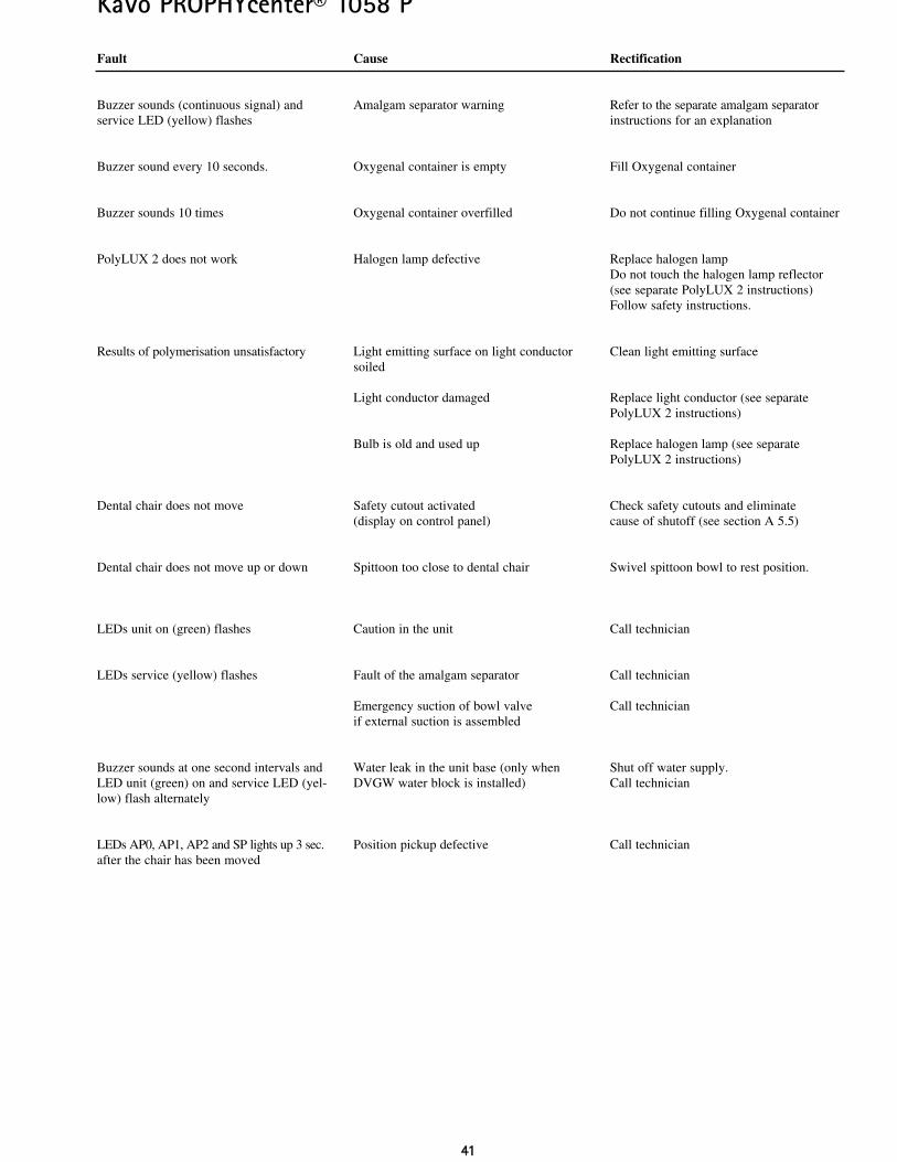
Fault
Nothing functions
Cold light does not function
No spray at the instruments
Turbine makes loud noises when running
Poor spray at the instruments
Leak in the instruments
Water in return-air filter
Suction hoses do not operate
4411
KaVo PROPHYcenter® 1058 P
Fault
Buzzer sounds (continuous signal) andservice LED (yellow) flashes
Buzzer sound every 10 seconds.
Buzzer sounds 10 times
PolyLUX 2 does not work
Results of polymerisation unsatisfactory
Dental chair does not move
Dental chair does not move up or down
LEDs unit on (green) flashes
LEDs service (yellow) flashes
Buzzer sounds at one second intervals andLED unit (green) on and service LED (yel-low) flash alternately
LEDs AP0, AP1, AP2 and SP lights up 3 sec.after the chair has been moved
Cause
Amalgam separator warning
Oxygenal container is empty
Oxygenal container overfilled
Halogen lamp defective
Light emitting surface on light conductorsoiled
Light conductor damaged
Bulb is old and used up
Safety cutout activated (display on control panel)
Spittoon too close to dental chair
Caution in the unit
Fault of the amalgam separator
Emergency suction of bowl valveif external suction is assembled
Water leak in the unit base (only whenDVGW water block is installed)
Position pickup defective
Rectification
Refer to the separate amalgam separatorinstructions for an explanation
Fill Oxygenal container
Do not continue filling Oxygenal container
Replace halogen lampDo not touch the halogen lamp reflector(see separate PolyLUX 2 instructions)Follow safety instructions.
Clean light emitting surface
Replace light conductor (see separatePolyLUX 2 instructions)
Replace halogen lamp (see separatePolyLUX 2 instructions)
Check safety cutouts and eliminate cause of shutoff (see section A 5.5)
Swivel spittoon bowl to rest position.
Call technician
Call technician
Call technician
Shut off water supply.Call technician
Call technician
4422
KaVo PROPHYcenter® 1058 P
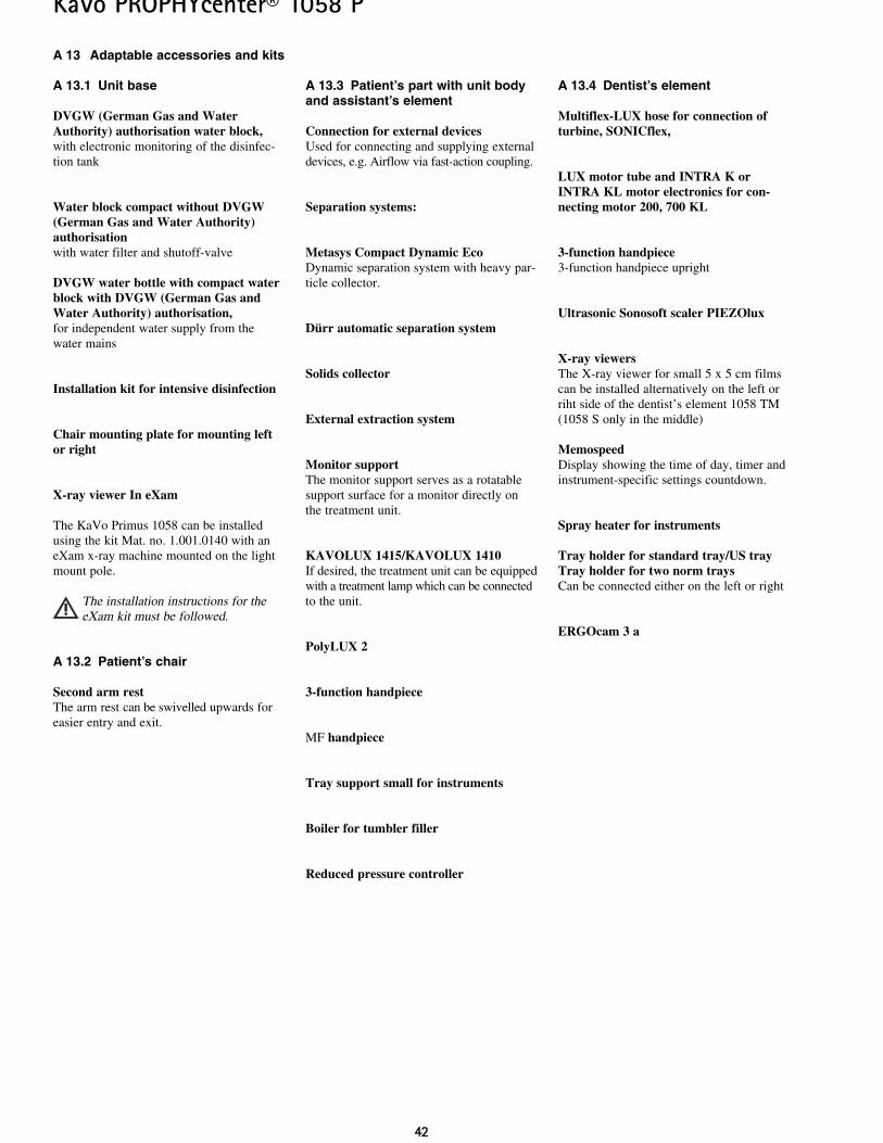
A 13.4 Dentist’s element
Multiflex-LUX hose for connection ofturbine, SONICflex,
LUX motor tube and INTRA K orINTRA KL motor electronics for con-necting motor 200, 700 KL
3-function handpiece3-function handpiece upright
Ultrasonic Sonosoft scaler PIEZOlux
X-ray viewersThe X-ray viewer for small 5 x 5 cm filmscan be installed alternatively on the left orriht side of the dentist’s element 1058 TM(1058 S only in the middle)
MemospeedDisplay showing the time of day, timer andinstrument-specific settings countdown.
Spray heater for instruments
Tray holder for standard tray/US trayTray holder for two norm traysCan be connected either on the left or right
ERGOcam 3 a
A 13.3 Patient’s part with unit bodyand assistant’s element
Connection for external devicesUsed for connecting and supplying externaldevices, e.g. Airflow via fast-action coupling.
Separation systems:
Metasys Compact Dynamic EcoDynamic separation system with heavy par-ticle collector.
Dürr automatic separation system
Solids collector
External extraction system
Monitor supportThe monitor support serves as a rotatablesupport surface for a monitor directly onthe treatment unit.
KAVOLUX 1415/KAVOLUX 1410If desired, the treatment unit can be equippedwith a treatment lamp which can be connectedto the unit.
PolyLUX 2
3-function handpiece
MF handpiece
Tray support small for instruments
Boiler for tumbler filler
Reduced pressure controller
A 13 Adaptable accessories and kits
A 13.1 Unit base
DVGW (German Gas and WaterAuthority) authorisation water block,with electronic monitoring of the disinfec-tion tank
Water block compact without DVGW(German Gas and Water Authority)authorisationwith water filter and shutoff-valve
DVGW water bottle with compact waterblock with DVGW (German Gas andWater Authority) authorisation,for independent water supply from thewater mains
Installation kit for intensive disinfection
Chair mounting plate for mounting leftor right
X-ray viewer In eXam
The KaVo Primus 1058 can be installedusing the kit Mat. no. 1.001.0140 with aneXam x-ray machine mounted on the lightmount pole.
The installation instructions for theeXam kit must be followed.
A 13.2 Patient’s chair
Second arm restThe arm rest can be swivelled upwards foreasier entry and exit.
4433
KaVo PROPHYcenter® 1058 P
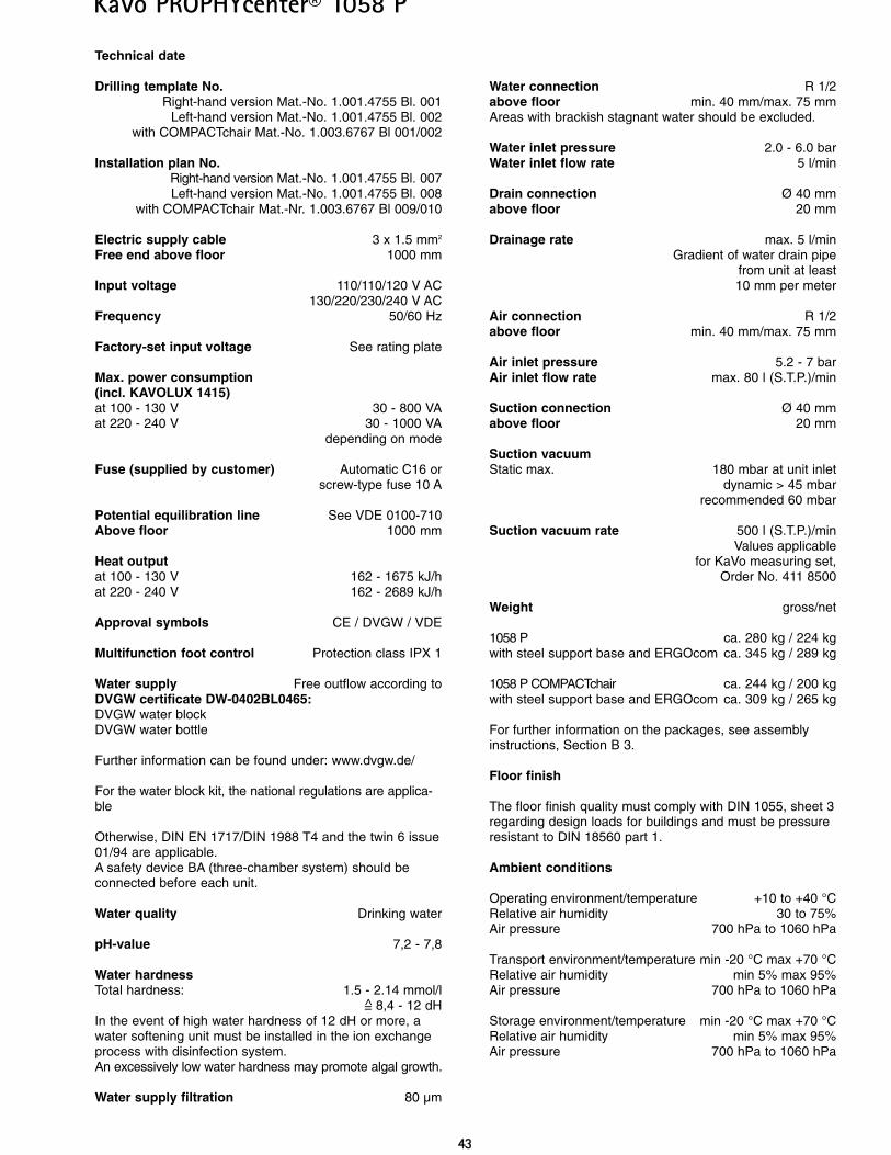
Technical date
Drilling template No.Right-hand version Mat.-No. 1.001.4755 Bl. 001
Left-hand version Mat.-No. 1.001.4755 Bl. 002with COMPACTchair Mat.-No. 1.003.6767 Bl 001/002
Installation plan No.Right-hand version Mat.-No. 1.001.4755 Bl. 007Left-hand version Mat.-No. 1.001.4755 Bl. 008
with COMPACTchair Mat.-Nr. 1.003.6767 Bl 009/010
Electric supply cable 3 x 1.5 mm2
Free end above floor 1000 mm
Input voltage 110/110/120 V AC130/220/230/240 V AC
Frequency 50/60 Hz
Factory-set input voltage See rating plate
Max. power consumption(incl. KAVOLUX 1415)at 100 - 130 V 30 - 800 VAat 220 - 240 V 30 - 1000 VA
depending on mode
Fuse (supplied by customer) Automatic C16 orscrew-type fuse 10 A
Potential equilibration line See VDE 0100-710Above floor 1000 mm
Heat outputat 100 - 130 V 162 - 1675 kJ/hat 220 - 240 V 162 - 2689 kJ/h
Approval symbols CE / DVGW / VDE
Multifunction foot control Protection class IPX 1
Water supply Free outflow according toDVGW certificate DW-0402BL0465:DVGW water blockDVGW water bottle
Further information can be found under: www.dvgw.de/
For the water block kit, the national regulations are applica-ble
Otherwise, DIN EN 1717/DIN 1988 T4 and the twin 6 issue01/94 are applicable.A safety device BA (three-chamber system) should beconnected before each unit.
Water quality Drinking water
pH-value 7,2 - 7,8
Water hardnessTotal hardness: 1.5 - 2.14 mmol/l
= 8,4 - 12 dHIn the event of high water hardness of 12 dH or more, awater softening unit must be installed in the ion exchangeprocess with disinfection system. An excessively low water hardness may promote algal growth.
Water supply filtration 80 µm
Water connection R 1/2above floor min. 40 mm/max. 75 mmAreas with brackish stagnant water should be excluded.
Water inlet pressure 2.0 - 6.0 barWater inlet flow rate 5 l/min
Drain connection Ø 40 mmabove floor 20 mm
Drainage rate max. 5 l/minGradient of water drain pipe
from unit at least10 mm per meter
Air connection R 1/2above floor min. 40 mm/max. 75 mm
Air inlet pressure 5.2 - 7 barAir inlet flow rate max. 80 l (S.T.P.)/min
Suction connection Ø 40 mmabove floor 20 mm
Suction vacuumStatic max. 180 mbar at unit inlet
dynamic > 45 mbarrecommended 60 mbar
Suction vacuum rate 500 l (S.T.P.)/minValues applicable
for KaVo measuring set,Order No. 411 8500
Weight gross/net
1058 P ca. 280 kg / 224 kgwith steel support base and ERGOcom ca. 345 kg / 289 kg
1058 P COMPACTchair ca. 244 kg / 200 kgwith steel support base and ERGOcom ca. 309 kg / 265 kg
For further information on the packages, see assemblyinstructions, Section B 3.
Floor finish
The floor finish quality must comply with DIN 1055, sheet 3regarding design loads for buildings and must be pressureresistant to DIN 18560 part 1.
Ambient conditions
Operating environment/temperature +10 to +40 °CRelative air humidity 30 to 75%Air pressure 700 hPa to 1060 hPa
Transport environment/temperature min -20 °C max +70 °CRelative air humidity min 5% max 95%Air pressure 700 hPa to 1060 hPa
Storage environment/temperature min -20 °C max +70 °CRelative air humidity min 5% max 95%Air pressure 700 hPa to 1060 hPa
4444
KaVo PROPHYcenter® 1058 P
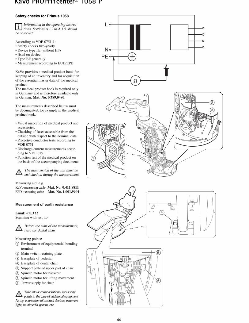
Safety checks for Primus 1058
Information in the operating instruc-tions, Sections A 1.2 to A 1.5, should
be observed.
According to VDE 0751-1:• Safety checks two-yearly• Device type IIa (without HF)• fixed on device• Type BF generally• Measurement according to EUD/EPD
KaVo provides a medical product book forkeeping of an inventory and for acquisitionof the essential master data of the medicalproduct.The medical product book is required onlyin Germany and is therefore available onlyin German, Mat. No. 0.789.0480.
The measurements described below mustbe documented, for example in the medicalproduct book.
• Visual inspection of medical product andaccessories.
• Checking of fuses accessible from theoutside with respect to the nominal data
• Protective conductor tests according to VDE 0751
• Discharge current measurements accor-ding to VDE 0751
• Function test of the medical product onthe basis of the accompanying documents
The main switch of the unit must beswitched on during the measurement.
Measuring aid: e.g.KaVo measuring cable Mat. No. 0.411.8811EPD measuring cable Mat. No. 1.001.9904
Measurement of earth resistance
Limit: < 0,3 ΩScanning with test tip
Before the start of the measurement,raise the dental chair
Measuring points:@ Environment of equipotential bonding
terminal” Main switch retaining plate# Baseplate of pedestal£ Baseplate of dental chairfi Support plate of upper part of chairÌ Spindle motor for backrest\ Spindle motor for lifting movement| Power supply for chair
Take into account additional measuringpoints in the case of additional equipment
X: e.g. connection of external devices, treatmentlight, multimedia system, etc.
L
NPE
Ω
@
fi
Ì\
£
”
#
4455
KaVo PROPHYcenter® 1058 P
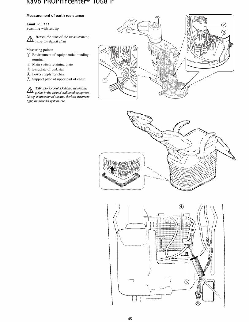
Measurement of earth resistance
Limit: < 0,3 ΩScanning with test tip
Before the start of the measurement,raise the dental chair
Measuring points:@ Environment of equipotential bonding
terminal” Main switch retaining plate# Baseplate of pedestal£ Power supply for chairfi Support plate of upper part of chair
Take into account additional measuringpoints in the case of additional equipment
X: e.g. connection of external devices, treatmentlight, multimedia system, etc.
@
”
#
£
fi
4466
KaVo PROPHYcenter® 1058 P
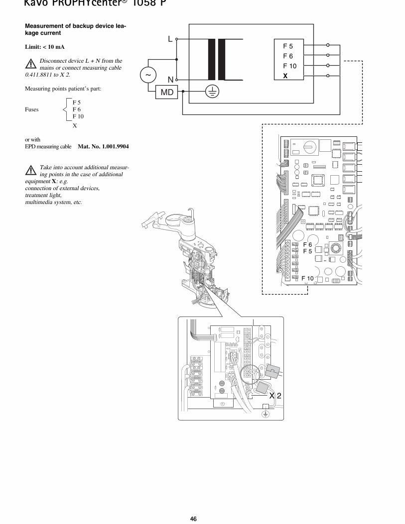
Measurement of backup device lea-kage current
Limit: < 10 mA
Disconnect device L + N from themains or connect measuring cable
0.411.8811 to X 2.
Measuring points patient’s part:
F 5Fuses F 6
F 10
X
or withEPD measuring cable Mat. No. 1.001.9904
Take into account additional measur-ing points in the case of additional
equipment X: e.g. connection of external devices,treatment light,multimedia system, etc.
L
N
MD
~
F 5
F 6
F 10
X
F 6F 5
F 10
X 2
4477
KaVo PROPHYcenter® 1058 P
~ MD
L
N
F 5
F 6
F 10
X
F 6F 5
F 10
X 2
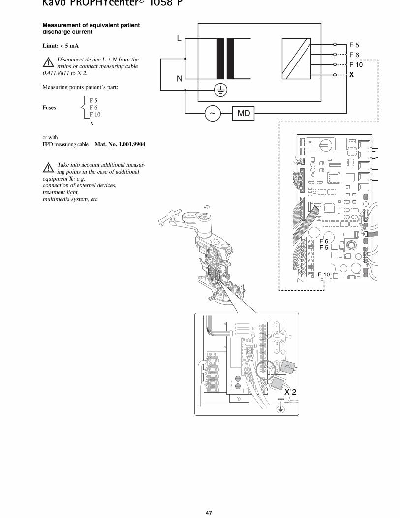
Measurement of equivalent patientdischarge current
Limit: < 5 mA
Disconnect device L + N from themains or connect measuring cable
0.411.8811 to X 2.
Measuring points patient’s part:
F 5Fuses F 6
F 10
X
or withEPD measuring cable Mat. No. 1.001.9904
Take into account additional measur-ing points in the case of additional
equipment X: e.g.connection of external devices,treatment light,multimedia system, etc.
KaVo Dental GmbH. D-88400 Biberach/RissTelefon +49 7351 56-0 Fax +49 7351 56-1488
Internet: www.kavo.com1.00
2.42
32
En
04
/05-
04
en