operating instructions mettler toledo multirange id3stx ... · system overview 8 guide for...
TRANSCRIPT

Operating instructions
METTLER TOLEDO MultiRangeID3sTx explosionproof weighing terminal
www.mt.com/support

Operating instructions 22000429C 05/08 3
ID3sTx
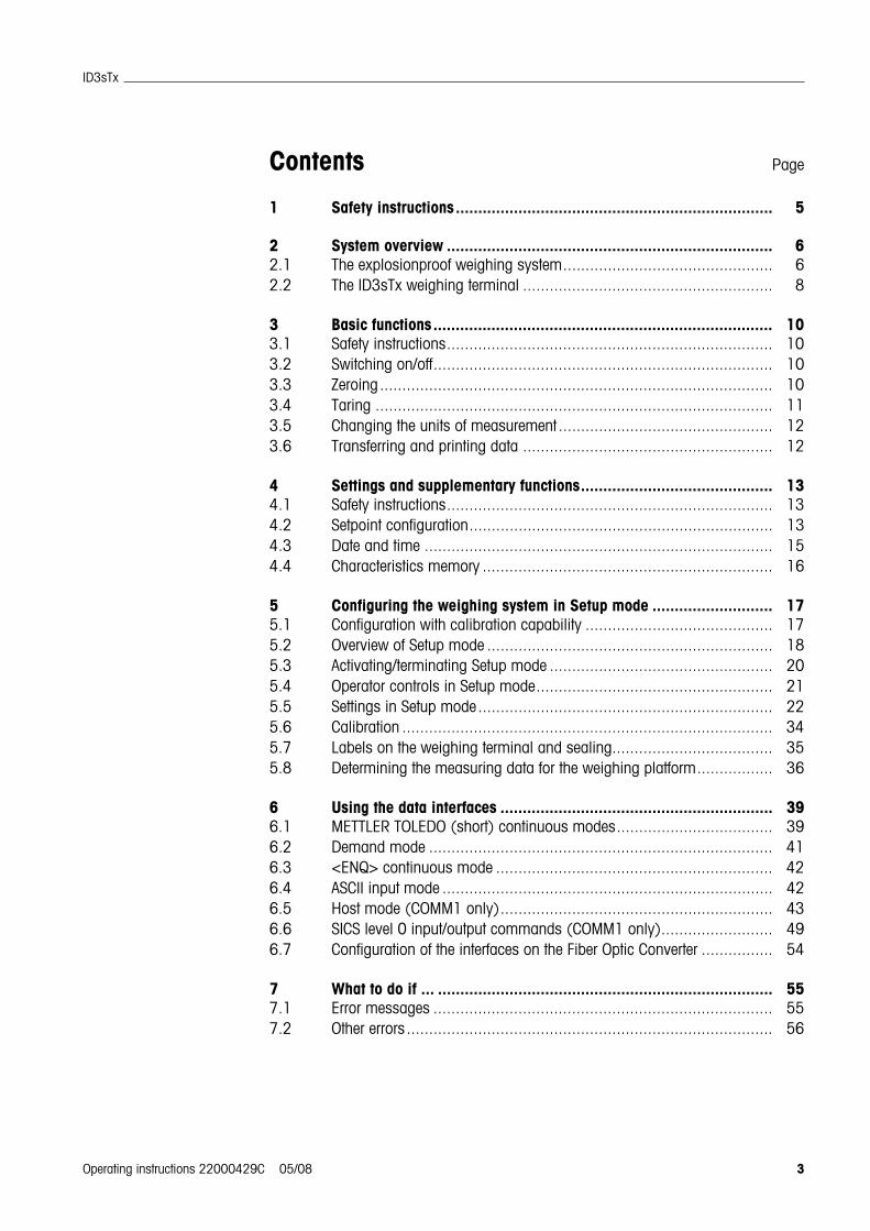
Contents Page
1 Safety instructions....................................................................... 5
2 System overview ......................................................................... 62.1 The explosionproof weighing system............................................... 62.2 The ID3sTx weighing terminal ........................................................ 8
3 Basic functions............................................................................ 103.1 Safety instructions......................................................................... 103.2 Switching on/off............................................................................ 103.3 Zeroing........................................................................................ 103.4 Taring ......................................................................................... 113.5 Changing the units of measurement ................................................ 123.6 Transferring and printing data ........................................................ 12
4 Settings and supplementary functions........................................... 134.1 Safety instructions......................................................................... 134.2 Setpoint configuration.................................................................... 134.3 Date and time .............................................................................. 154.4 Characteristics memory ................................................................. 16
5 Configuring the weighing system in Setup mode ........................... 175.1 Configuration with calibration capability .......................................... 175.2 Overview of Setup mode ................................................................ 185.3 Activating/terminating Setup mode .................................................. 205.4 Operator controls in Setup mode..................................................... 215.5 Settings in Setup mode.................................................................. 225.6 Calibration ................................................................................... 345.7 Labels on the weighing terminal and sealing.................................... 355.8 Determining the measuring data for the weighing platform................. 36
6 Using the data interfaces ............................................................. 396.1 METTLER TOLEDO (short) continuous modes................................... 396.2 Demand mode ............................................................................. 416.3 <ENQ> continuous mode .............................................................. 426.4 ASCII input mode .......................................................................... 426.5 Host mode (COMM1 only)............................................................. 436.6 SICS level 0 input/output commands (COMM1 only)......................... 496.7 Configuration of the interfaces on the Fiber Optic Converter ................ 54
7 What to do if ... ........................................................................... 557.1 Error messages ............................................................................ 557.2 Other errors .................................................................................. 56

4 Operating instructions 22000429C 05/08
ID3sTx
8 Cleaning and charging the battery................................................ 588.1 Safety instructions ........................................................................ 588.2 Cleaning...................................................................................... 588.3 Charging the battery...................................................................... 58
9 Technical data............................................................................. 609.1 General data ................................................................................ 609.2 Electrical data .............................................................................. 619.3 Functions .................................................................................... 629.4 Compatible weighing platforms ...................................................... 62
10 Accessories ................................................................................ 6310.1 Mechanical accessories ................................................................ 6310.2 Power supply............................................................................... 6410.3 Data interfaces ............................................................................. 64
11 Appendix .................................................................................... 6511.1 Table of Geo values ...................................................................... 65
Safety instructions
Guide for installers 22000429C 05/08 5
ID3sTx
1 Safety instructions
There is an increased risk of injury and damage when the explosionproof ID3sTxweighing terminal is used in a potentially explosive atmosphere.Special care must be taken when working in such hazardous areas. The code ofpractice is oriented to the "Safe Distribution" concept drawn up by METTLER TOLEDO.
Competence The ID3sTx weighing terminal may only be installed, maintained and repaired byauthorized METTLER TOLEDO service personnel.
The ID3sTx weighing terminal with built-in power supply unit may only be con-nected or disconnected to/from the mains by a qualified electrician.
Ex approval No modifications may be made to the terminal and no repair work may beperformed on the modules. Any weighing platform or system modules that areused must comply with the specifications contained in the installation instruc-tions. Non-compliant equipment jeopardizes the intrinsic safety of the system,cancels the Ex approval and renders any warranty or product liability claims nulland void.
The safety of a weighing system including the ID3sTx weighing terminal is onlyguaranteed when the weighing system is operated, installed and maintained inaccordance with the respective instructions.
Also comply with the following:
– the instructions for the system modules, – the relevant national regulations and standards,– the applicable statutory requirements for electrical equipment installed in
hazardous atmospheres in the respective country,– all instructions related to safety issued by the operator.
The explosion-protected weighing system must be checked to ensure compliancewith the requirements for safety before being put into service for the first time, fol-lowing any service work and every 3 years, at least.
Operation Prevent the build-up of static electricity. Always wear suitable working clotheswhen operating or performing service work on the system.
Never use protective hoods from other weighing terminals.
Battery operation Always charge the batteries in a safe zone. Install and use METTLER TOLEDObattery chargers in the safe zone. Use the chargers specified by METTLERTOLEDO only.
Never try to open or repair batteries. They are intrinsically safe and are irrepar-able. Recycle defective batteries or dispose of them in the proper manner.

System overview
6 Guide for installers 22000429C 05/08
ID3sTx
2 System overview
2.1 The explosionproof weighing systemA weighing system designed for operation in hazardous zones 1 and 21 comprisesthe following components:
ID3sTx weighing terminal
The weighing terminal designed for use in a potentially explosive atmosphere is char-acterized by the following features:
• Stainless steel enclosure with large high-contrast liquid-crystal display.
• Numerical keypad to enter default tare values, for example.
• Power supplied by an internal or external battery or an internal power supply unit.
• Up to 2 fiber-optic data interfaces for data communication with peripheral equip-ment, such as printer, PC or setpoint controller.
Type of protection II 2 G EEx ib IIC T4II 2 D IP65 T 50 °C
IP degree of protection IP65
Max. 100m
RWMx
Ex1 system solution
Max.100m
LWL,
Dual ChannelFiber Optic Converter
RSPC
CL
Printer
Hazardous zone Safe zone
1 weighingmachineconnection
ID3sTx weighing terminal
max. 300m
Ext. battery
Max. 1.5 m
PBA430xMax. 3m
D..TxPTA459xPUA579x

System overview
Guide for installers 22000429C 05/08 7
ID3sTx
Intrinsically safe powersupply
There are 3 intrinsically safe power supplies to the weighing terminal and weighingplatform for the ID3sTx weighing terminal:
Internal batteryType of protection II 2 G EEx ib IIC T4When the ID3sTx is used in a zone 21 area, the internal battery may only beoperated within the housing of the ID3sTx.
External batteryThe terminal is equipped with a 1.5 m cable to enable connection to an external bat-tery.Type of protection II 2 G EEx ib IIC T4
II 2 D IP65 T 120 °C
Internal AC power supply unitType of protection II 2 G EEx m e [ib] IIC T4Preassembled mains cable 5 mIn a hazardous zone, the terminal must be connected up to the mains in accordancewith the applicable national installation regulations.When the ID3sTx is used in a zone 21 area, the internal AC power supply unit mayonly be operated within the housing of the ID3sTx.
Weighing platforms …x METTLER TOLEDO weighing platforms are available for various maximum loads andreadability requirements, equipped with explosionproof extension measuring cells.Weighing platforms manufactured by other companies may only be connected to theterminal if they fulfil the specifications in the terminal connection diagram (see guidefor installers).
DN…Tx, PTA459x, PUA579xType of protection II 2 G EEx ia IIC T4
II 2 D IP68 T 80 °CIP degree of protection IP68Preassembled cable 5 m long
DB…Tx, DCS...Tx Type of protection II 2 G EEx ia IIC T4
II 2 D IP67 T 80 °CIP degree of protection IP67Preassembled cable 5 m long

System overview
8 Guide for installers 22000429C 05/08
ID3sTx
PBA430xType of protection II 2 G EEx ia IIC T4
II 2 D IP65 T 150 °CIP degree of protection IP68, IP69KPreassembled cable 1.5 m capacity ≤ 30 kg 2.5 m capacity ≥ 60 kg
RWM1x (0.5 t / 1 t)Type of protection II 2 G EEx ib IIC T6
II 2 D IP67 T 70 °CIP degree of protection IP67Preassembled cable 5 m longSystem solution Ex1 is required for RWM1x. Up to 4 RWMx can be connected to thissystem solution. Preassembled cable: 5 m long
Dual ChannelFiber Optic Converter
The Dual Channel Fiber Optic Converter has 2 data interfaces; it may only by used inthe safe zone. An RS232 or CL terminal is available at each data interface. The weighing terminal must be equipped with one or two fiber optic data interfacesfor data transfer.
2.2 The ID3sTx weighing terminal
2.2.1 Display
1 Battery symbol – lights up when the battery needs charging
2 Clock symbol – lights up when the time is displayed or entered
3 6-digit digital display
4 Weight units
5 Status indicators – one of the symbols lights up for stationary weight values
2
3 4
51

System overview
Guide for installers 22000429C 05/08 9
ID3sTx
2.2.2 Keypad
1 CLEAR
2 PRINT
3 UNITS
4 ZERO
5 FUNCTION supplementary functions are activated in combination with numerical keys
6 Numeric keypad
7 ENTER
8 OFF
9 ON
10 RECALL
11 TARE
2.2.3 Connections
1 Battery compartment – for internal battery only
2 Power supply – external battery (with cable), AC power supply unit (with cable);terminal not provided when internal battery used
3 Optional interface terminals
4 Weighing platform terminal
5 Equipotential bonding terminal
CLEAR
T
UNITS
ZERO
0
ID
7
FUNCTION
F
SP
4
SP
1
T&D
8
5
SP
2
SLEEP
9
TOL.2
6
SP
3
ENTER
TARE
T
RECALL
ON
OFF
TOL.1
0
T
1
2
3
4
5 6 7 8
11
10
9
11

Basic functions
10 Operating instructions 22000429C 05/08
ID3sTx
3 Basic functions
3.1 Safety instructions
EXPLOSION HAZARD
Always comply with the safety instructions in Chapter 1 when working with theID3sTx weighing terminal.
3.2 Switching on/off
3.2.1 Switching on
1. Remove any load acting on the weighing platform.
2. Press the ON key; the display indicates 0.000 kg.
3.2.2 Switching off manually
1. Remove any load acting on the weighing platform.
2. Press the OFF key; the display goes dark.
CautionThe FUNCTION + 9 key combination must be used to switch the terminal off insteadof the OFF key if automatic switch-off with retention of the zero and tare values whenreactivated has been programmed in Setup mode. Error message E11 will otherwiseappear when the terminal is switched on again.
3.2.3 Automatic switch-off
Requirement
– Sleep mode must have been activated in Setup.
The ID3sTx weighing terminal switches off automatically if no actions are performedat the terminal within the period programmed in Setup.
CautionThe FUNCTION + 9 key combination must be used to switch the terminal off insteadof the OFF key if automatic switch-off with retention of the zero and tare values whenreactivated has been programmed in Setup mode. Error message E11 will otherwiseappear when the terminal is switched on again. The entered zero point, tare valueand ID number are then erased. To remedy the problem, refer to Section 7.1.
3.3 ZeroingZeroing compensates for the weight of dust and slight soiling on the load plate. Zero-ing can only be performed within the range programmed in Setup mode.
1. Remove any load acting on the weighing platform.
2. Press the ZERO key; the displayed value changes to 0.000 kg.

Basic functions
Operating instructions 22000429C 05/08 11
ID3sTx
3.4 Taring
3.4.1 Taring manually
1. Place an empty container on the plate.
2. Press the TARE key; the displayed value is reset to 0.000 kg and the "Net" symbollights up.
All values displayed from now on are net weights referred to the stored tare weight.
3.4.2 Tare weight input
1. Place a full container on the weighing platform.
2. Use the numeric keypad to enter the known weight of the container.
3. Press the TARE key; the display changes to the net weight display, and the "Net" symbol lights up.
All values displayed from now on are net weights referred to the stored tare weight.
NoteIf restrictions have been entered for the taring function in Setup, you will only be ableto enter a known tare weight when there is no load acting on the weighing platform.
3.4.3 Recalling the tare weight
Press the RECALL key.
The stored tare weight is displayed briefly. The weighed net value is then returned tothe display.
3.4.4 Erasing the tare weight
Erasing the tare weight manually
Requirement
– The taring function must be set to "not protected" in Setup.
Press the CLEAR key.
The entered tare weight is erased and gross weight values are displayed again.
Erasing the tare weight automatically
Requirement
– Automatic tare value erasure must have been activated in Setup.
The tare weight is erased automatically when the load is removed from the weighingplatform following the weighing operation.

Basic functions
12 Operating instructions 22000429C 05/08
ID3sTx
3.5 Changing the units of measurementNotes
• The units available for selection are kg, lb and a user-defined unit of measure-ment.
• The "Change units" function will not be available if the statutory calibration require-ments in the country concerned only permit one unit of measurement.
• The user-defined unit is displayed without a unit symbol.
Requirements
– The weighing system has been calibrated in kg or lb.
– Unit changeover has been activated in Setup.
– If required: the user-defined unit has been defined.
Press the UNITS key; the current weight is displayed in the second unit ofmeasurement.
3.6 Transferring and printing dataRequirement
– The optional serial interface has been installed and demand mode has been acti-vated in Setup.
Press the PRINT key.The currently displayed data is transferred via the serial interface and is output inaccordance with the formatting programmed in Setup.
NoteIt will not be possible to transfer and print data if the weighing platform
• is not at rest,
• is operating at high resolution, or
• is in underload or overload range.

Settings and supplementary functions
Operating instructions 22000429C 05/08 13
ID3sTx
4 Settings and supplementary functions
4.1 Safety instructions
EXPLOSION HAZARD
Always comply with the safety instructions in Chapter 1 when working with theID3sTx weighing terminal.
4.2 Setpoint configurationSetpoint values can be used to increase or reduce the metered quantity of weighedgoods in metering applications. The ID3sTx offers the following facilities for thisaccording to the setting programmed in Setup:
Filling to setpoint at the same metering speed4 metering operations can be programmed with this procedure. The meteringoperation is determined by the following values:
• Setpoint = Target weight
• After-flow compensation
• Tolerance, can be selected as a setpoint tolerance or a zero tolerance
"4 setpoints" must be set in Setup for this.
Filling with coarse and fine flow rateThis involves filling the material into containers at 2 different speeds. The materialflows at high speed (coarse flow) up to a programmable changeover point, afterwhich it continues to flow at a slower speed (fine flow) up to the cut-off point. It is therefore possible to program 2 different metering operations. The metering operation is determined by the following values:
• Setpoint = Target weight
• After-flow compensation
• Changeover point between coarse and fine flow
• Tolerance, can be selected as a setpoint tolerance or a zero tolerance
"2 setpoints" must be set in Setup for this.
After-flow compensation Material continues to flow after the filling operation is terminated. The cut-off point forthe filling machine must be selected in such a way as to ensure that the final weightis achieved following the after-flow to ensure that the actual weight is not higher orlower than the required value.

Settings and supplementary functions
14 Operating instructions 22000429C 05/08
ID3sTx
4.2.1 Entering setpoint values for the same metering speed
Requirement
– "4 setpoints" activated in Setup.
NoteThe input prompts must be confirmed without delay as the weighing terminal other-wise returns to normal mode.
Entering the targetweight
1. Press the FUNCTION key and select one of the four setpoint values using thenumerical keypad; [SP- x] appears on the display.
2. Press the ENTER key; the programmed target weight appears on the display.
3. Use the numerical keypad to enter a new target weight and confirm it by pressingthe ENTER key or press the ENTER key to confirm the displayed target weight.
Entering the after-flowcorrection factor
4. [Pr- x] is displayed. Press the ENTER key; the programmed cut-off point appearson the display.
5. Use the numerical keypad to enter a new cut-off point and confirm it by pressingthe ENTER key or press the ENTER key to confirm the current cut-off point.
Entering tolerance If parameter 82 = 0 and parameter 83 = 0: Enter zero tolerance for target value 1 and target value 2.
6. Press the FUNCTION key and the 5 key to select the tolerance for setpoint 1 or the6 key to select the tolerance for setpoint 2. [0tol - x] appears on the display.
7. Press the ENTER key; the programmed zero tolerance appears on the display.
8. Use the numerical keypad to enter a new tolerance and confirm by pressing theENTER key or press the ENTER key to confirm the current tolerance.
9. Press the ENTER key again; the weighing terminal returns to normal mode.
If parameter 82 = 1 and parameter 83 = 1: Enter target value tolerance for target value 1 and target value 2.
6. [tol- x] is displayed. Press the ENTER key; the currently set shutoff point appearsin the display.
7. Use the numerical keypad to enter a new tolerance and confirm by pressing theENTER key or press the ENTER key to confirm the current tolerance.
8. Press the ENTER key again; the weighing terminal returns to normal mode.
4.2.2 Entering two setpoint values
Requirement
– "2 setpoints" activated in Setup.
NoteThe input prompts must be confirmed without delay as the weighing terminal other-wise returns to normal mode.

Settings and supplementary functions
Operating instructions 22000429C 05/08 15
ID3sTx
Entering the targetweight
1. Press the FUNCTION key and, using the numerical keypad, select one of the twosetpoints; [SP- x] appears on the display.
2. Press the ENTER key; the programmed target weight appears on the display.
3. Use the numerical keypad to enter a new target weight and confirm by pressingthe ENTER key or press the ENTER key to confirm the programmed target weight.
Entering thecoarse flow / fine flow
switchover point
4. [Dr- x] is displayed. Press the ENTER key; the currently programmed switchoverpoint appears on the display.
5. Use the numerical keypad to enter a new switchover point and confirm by press-ing the ENTER key or press the ENTER key to confirm the programmed switchoverpoint.
Entering the after-flowcorrection factor
6. [Pr- x] is displayed. Press the ENTER key; the currently programmed cut-off pointappears on the display.
7. Use the numerical keypad to enter a new cut-off point and confirm by pressing theENTER key or press the ENTER to confirm the currently programmed cut-off point.
Entering the tolerance 8. [tol- x] or [0tol- x] is displayed. Press the ENTER key; the currently programmedcut-off point appears on the display.
9. Use the numerical keypad to enter a new tolerance and confirm by pressing theENTER key or press the ENTER to confirm the currently programmed tolerance.
10.Press the ENTER key again; the weighing terminal returns to normal mode.
4.3 Date and timeThe time is always displayed in 24-hour format; the date is displayed in accordancewith the format specified in Setup.NoteThe input prompts must be confirmed without delay as the weighing terminal other-wise returns to normal mode.
Entering the time 1. Press the FUNCTION key followed by the 8 key; the set time appears on the dis-play.
2. Press the ENTER key to confirm the displayed time or the CLEAR key to erase thedisplayed time.
3. Use the numerical keypad to enter the time in 24-hour format and confirm bypressing the ENTER key.
The time has now been stored and the set date appears on the display automatically.
Entering the date 4. Press the ENTER key to confirm the displayed date or the CLEAR key to erase thedisplayed date.
5. Use the numerical keypad to enter the date in the displayed format.
6. Press the ENTER key; the weighing terminal returns to normal mode.

Settings and supplementary functions
16 Operating instructions 22000429C 05/08
ID3sTx
4.4 Characteristics memoryThe ID3sTx is equipped with a characteristics memory to facilitate identification of theweighing system or individual weighing operations. You can perform the followingoperations with the 6-digit ID number stored in this memory:
• change it,
• print it or
• transfer it via the data interface.
NoteThe input prompts must be confirmed without delay as the weighing terminal other-wise returns to normal mode.
4.4.1 Changing the ID number
1. Press the FUNCTION key, followed by the 7 key; the current content of the charac-teristics memory (ID number) appears on the display.
2. Press the ENTER key to confirm the current ID number or the CLEAR key to erasethe current ID number.
3. Use the numerical keypad to enter another 6-digit ID number.
4. Press the ENTER key; the weighing terminal returns to normal mode.

Configuring the weighing system in Setup mode
Operating instructions 22000429C 05/08 17
ID3sTx
5 Configuring the weighing system in Setup mode
EXPLOSION HAZARD
The weighing terminal enclosure may only be opened and programmed in Setupmode by suitable qualified personnel.
5.1 Configuration with calibration capabilityAll METTLER TOLEDO weighing platforms of the D...Tx, PTA459x, PUA579x andPBA430x can be operated with the ID3sTx in a configuration with calibration capabil-ity. Special-purpose weighing platforms, comprising METTLER TOLEDO RWM1x mod-ules, and weighing platforms manufactured by other companies may only be oper-ated in a configuration with calibration capability if they fulfill the requirements forminimum sensitivity for each calibration value, refer to Section 5.8.
Settings approved for calibrationNot all of the settings that are possible in Setup mode are approved for calibration.Restrictions are imposed on the parameters given in the table below for operationsthat are subject to calibration requirements.The weighing system cannot be calibrated if the setting for one of the parametersgiven in the table is not approved.Parameters that are not included in this table do not affect calibration capability.
Parameter Settings approved for calibration Remarks
13 1 = ≤ ±0.5 d Automatic zeroing within the ≤ ±0.5 d range only
15 1 = ±2 % Resetting range ±2 % of the maximum load
16 1 = ≥ 0.5 d2 = ±1 d
Values that only differ by the set value are regarded as being stationary weight values
18 Entered value ≤ maximum load +9 e Overload display when the maximum load has been exceeded by 9 e at the latest
37, 57 0 = Print negative net weights with sign
43, 63 1 = Printout with weight unit
71 0 = No unit changeover1 = Changeover kg <-> lb
Undefined units are not permitted in opera-tions that are subject to calibration require-ments
74 1 = PT Numerically specified tare values must be identified by PT
91 0 = Normal resolution Higher resolution not permitted for opera-tions that are subject to calibration require-ments

Configuring the weighing system in Setup mode
18 Operating instructions 22000429C 05/08
ID3sTx
5.2 Overview of Setup mode• Settings approved for calibration are identified by a *.
• Factory setting are printed in bold type.
00 Calibration
01 Calibration unit0 = lb1 = kg2 = g3 = t
02 Linearity compensation0 = off1 = on
04 Maximum load1 ... 100000
05 Reading accuracyEnter numerical increment and positionof the decimal point
08 Calibration0 = terminate calibration1 = start calibration
09 Update rate0 = 16 measurements/s1 = 14 measurements/s2 = 12 measurements/s3 = 10 measurements/s4 = 9 measurements/s5 = 8 measurements/s6 = 7 measurements/s
10 Zeroing and filters
11 Set absolute zero 0 = go on to 121 = save
12 Set span 0 = go on to 131 = enter the span
13 Automatic zeroing0 = off
* 1 = within range ≤ ±0.5 d2 = within range ≤ ±1 d3 = within range ≤ ±3 d4 = within range ≤ ±0.5 d5 = within range ≤ ±1 d6 = within range ≤ ±3 d
14 Automatic zeroingat switch-on 0 = off (Restart active)1 = ±2 % of capacity 2 = ±10 % of capacity
15 Automatic zeroingby pressing a key 0 = off
*1 = ±2 % of capacity2 = ±20 % of capacity
16 Standstill check0 = off
*1 = ≥ 0.5 d *2 = ±1.0 d
3 = > 2.0 d4 = > 3.0 d
17 Vibration adapter(filter settings)0 = 0.25 s 1 = 0.35 s 2 = 0.60 s 3 = 0.75 s 4 = 1.2 s 5 = 1.6 s 6 = 2.0 s 7 = 2.4 s
18 Overload/underloaddisplayEnter weight value
*Approved for calibration: max. + 9 e
19 Geo value 01... 26, 19
20 Tare and timers
21 Tare0 = off1 = by pressing a key 2 = by pressing a key and
tare preset
22 Protect taring function0 = not protected1 = protected
24 Tare autoclear0 = off1 = clear tare automatically
at zero gross weight
25 Weighing system ID01 ... 99
26 Date format0 = MM:DD:YY1 = DD:MM:YY2 = YY:MM:DD
27 Sleep mode0 = off1... 99 = switch-off time
in min.
30/50COMM1/COMM2
31/51 Output operatingmodes
0 = no serial interface1 = continuous mode2 = demand mode3 = <ENQ> continuous
mode4 = short continuous mode5 = host mode (31 only)6 = SICS level 0 mode
(31 only)
32/52 ASCII remoteinput mode
0 = off1 = on
33/53 Baud rate3001200240048009600
34/54 Parity bit0 = 01 = odd2 = even3 = 14 = no parity bit
35/55 Number of data bits 0 = 7 bits1 = 8 bits
36/56 Checksum0 = no check byte1 = check byte will be
transferred
37/57 Print net weight with positive sign(in demand mode only)
*0 = print normally 1 = display normally, but
print with pos. sign 2 = display and print with
pos. sign
38/58 STX (in demand mode only)
0 = no STX transfer1 = STX transfer
39/59 Line format whenprinting(in demand mode only)
0 = one line1 = several lines

Configuring the weighing system in Setup mode
Operating instructions 22000429C 05/08 19
ID3sTx
41/61 Data fields for printout(in demand mode only)
0 = field off1 = displayed weight2 = gross weight3 = tare weight4 = net weight5 = weighing system
number6 = empty line7 = date/time8 = characteristics memoryFactory setting: 523400
42/62 Print with higher resolution(in demand mode only)
0 = normal resolution 1 = higher resolution
43/63 Print weight unit(in demand mode only)
0 = do not print *1 = print kg/lb
44/64 Print the time0 = 24-hour format1 = 12-hour format
45 COMM1 link(in host mode only)0 = address each ID3sTx
directly1 = address all ID3sTx in
in series
70 Country-specific settings
71 Unit switchover *0 = Unit key inactive *1 = switch kg/lb
2 = switch between calibrated and user-defined unit
72 Weight unit at switch-onCalibration unit lb/kg(Parameter 01 = 0/1); Switchover lb/kg orno switchover (Parameter 71 = 0/1):0 = kg1 = lb
Calibration unit kg(Parameter 01 = 1); Switchover calibrated/user-defined unit (Parameter 71 = 2): 0 = kg1 = user-defined unit
Calibration unit lb (Parameter 01 = 0); Switchover calibrated/user-defined unit (Parameter 71 = 2): 0 = user-defined unit1 = lb
73 Print weight value in brackets (in demand mode only)0 = print normally 1 = print in brackets
74 Tare symbol(in demand mode only)0 = print T
*1 = print PT
75 Decimal point/decimal comma0 = display and print
decimal point 1 = display and print
decimal comma
76 Display zero (Z) 0 = Z off
*1 = display Z at ±0.25 dof the gross zero value
2 = display Z at gross or net zero
77 Tare autoclear following printout 0 = off1 = on
78 Printout initiation0 = printout for every key
depression1 = one printout per
weighing operation (at standstill)
2 = automatic printoutat standstill
79 Excursion for triggeringof automatic printout0 = no excursion value
defined1 = 10 d2 = 100 d3 = 500 d
80 Setpoint values
81 Setpoint mode0 = off1 = 4 setpoints2 = 2 setpoints
82 Tolerance 1for 4 setpoints:0 = zero tolerance assigned
to key 51 = tolerance for setpoint 1for 2 setpoints:0 = zero tolerance1 = setpoint 1
83 Tolerance 2for 4 setpoints:0 = zero tolerance assigned
to key 61 = tolerance for setpoint 2for 2 setpoints:0 = zero tolerance1 = setpoint 2
84 Setpoint status bit0 = setpoint status bit from
0 to 1 for positiveweight signal
1 = setpoint status bit from0 to 1 when absoluteweight > setpoint value
90 Miscellaneous
91 High resolution *0 = normal resolution
1 = high resolution
92 User-defined unit, position of decimal point in theconversion factor[0.0001]Change value with numerical key 0 and confirm with the ENTER key
93 User-defined unit, conversion factor[XXXXXX]Enter conversion factor0 = no user-defined unit
94 User-defined unit, position of decimal point in the display0.00010.0010.010.11
95 Interface Board Function0 = off1 = on
96 External control 0 = off1 = tare2 = zero setting3 = print
99 Restore factory settings for parameters0 = selected settings
are active1 = restore US factory
settings2 = restore European
factory settings [SUrE] is displayed.Confirm reset with key 1 or 2.

Configuring the weighing system in Setup mode
20 Operating instructions 22000429C 05/08
ID3sTx
5.3 Activating/terminating Setup mode
CAUTIONIf the ID3sTx weighing terminal is used for operations that are subject to calibrationrequirements, the calibration seal is destroyed when the enclosure is opened toaccess Setup mode.
The weighing system must be calibrated and sealed again following terminationof Setup mode.
CAUTIONFluctuations or interruptions in the power supply to the weighing terminal while inSetup mode can lead to calibration errors or a loss of data. A lot of energy is requiredin Setup mode. This detrimentally affects the service life of the battery.
Check the battery symbol. Do not activate Setup mode if the battery symbol lightsup.
Insert a spare battery and put the original battery on charge.
NoteYou do not need to switch the ID3sTx weighing terminal off in order to access Setupmode.
5.3.1 Opening the enclosure
CAUTIONThe clips on the enclosure cover have sharp edges.
Avoid touching the cover in the areas around the (four) clips to prevent injury toyour fingers.
1. Slide a screwdriver into the holes at the front of the cover until you hear an aud-ible snapping noise and the front clips are released.
2. Lift the cover at the front and press towards the read. The rear clips are releasedaudibly.
3. Lift the cover and remove carefully towards the front. The main PCB, which is fit-ted inside the cover, is now accessible.

Configuring the weighing system in Setup mode
Operating instructions 22000429C 05/08 21
ID3sTx
5.3.2 Setting jumper
Set jumper W2, on the right-hand side at the front of the main PCB, to the INposition.
The display indicates [--].
5.3.3 Terminating Setup mode
CAUTIONRisk of data loss.
Never switch the ID3sTx weighing terminal off while it is in Setup mode, or youwill lose all of your settings and changes.
1. Remove jumper W2 to transfer the changes to the memory and return to normalmode.
2. Replace the cover on the weighing terminal enclosure and press down until all ofthe clips are heard to latch into place, making sure that no cables are trapped.
CAUTIONObserve the calibration specifications.
If you are using the ID3sTx weighing terminal for operations that are subject tocalibration requirements, make sure that all settings are approved for calibrationbefore terminating Setup mode, refer to the overview in Section 5.2.
5.4 Operator controls in Setup modeThe Setup mode for the ID3sTx weighing terminal is divided into groups of settingparameters.
• When a group is called up, the parameters for the respective group are automati-cally called up in succession (exception: group 30/50).
• Individual parameters can also be called up directly.
W2

Configuring the weighing system in Setup mode
22 Operating instructions 22000429C 05/08
ID3sTx
Calling a group
1. Use the numerical keypad to enter the group number, e.g. "10". The first parameter of the group, e.g. "11", appears on the display.
2. Enter the setting on the keypad.
3. Confirm by pressing the ENTER key.The next parameter for the group appears on the display.
Calling parameters directly
1. Use the numerical keypad to enter the parameter number, e.g. "11".Parameter "11" appears on the display.
2. Enter the setting on the keypad.
3. Confirm by pressing the ENTER key.
Changing the setting
1. Use the numerical keypad to enter the required setting.
2. Press the 0 key to move the decimal point.
Switching between predefined settings
Press the 0 key.
Erasing an input error
Press the CLEAR key.
Returning to the previous step
Press the ZERO key.
Adopting the setting
Press the ENTER key.
5.5 Settings in Setup mode
5.5.1 Overview of parameter groups
00 Calibration (refer to 5.5.2)
10 Zeroing and filters (refer to 5.5.3)
20 Tare and timers (refer to 5.5.4)
30 Serial interface COMM1 (refer to 5.5.5)
50 Serial interface COMM2 (refer to 5.5.5)
70 Country-specific settings (refer to 5.5.6)
80 Setpoint values (refer to 5.5.7)
90 Miscellaneous (refer to 5.5.8)

Configuring the weighing system in Setup mode
Operating instructions 22000429C 05/08 23
ID3sTx
Notes
• Settings that are approved for calibration are identified by an *.
• If none of the settings for a parameter is identified with an *, then the parameterdoes not affect calibration capability.
• Factory settings are printed in bold type.
5.5.2 Parameter group 00 "Calibration"Parameters 01 to 05 are called up, one after the other.Parameter 04 can also be called up directly.
01 Calibration unit0 = lb1 = kg2 = g3 = t
02 Linearity compensation0 = off1 = on
04 Maximum loadStored value appears.Permitted values: 1... 100000
05 Reading accuracyStored value appears. Enter the numerical increment and the position of the decimal point.
Example The reading accuracy for a weighing platform with 30 kg maximum load and a reso-lution of 3000 d amounts to 0.01 kg.
Enter the value 0.01 and press the ENTER key to confirm.
08 CalibrationNoteA weighing platform must be calibrated before it can be used in conjunctionwith the ID3sTx weighing terminal. Failure to comply with this ruling may resultin errors occurring if the calibration data stored in the I/O ROM is not the sameas the data stored in the weighing platform. 0 = terminate calibration1 = start calibration (refer to Section 5.6 for the calibration procedure)

Configuring the weighing system in Setup mode
24 Operating instructions 22000429C 05/08
ID3sTx
09 Update rateThis parameter can only be selected following calibration.0 = 16 measurements/s1 = 14 measurements/s2 = 12 measurements/s3 = 10 measurements/s4 = 9 measurements/s5 = 8 measurements/s6 = 7 measurements/s
5.5.3 Parameter group 10 "Zeroing and filters"Parameters 11 to 19 are called up, one after the other.All of the parameters in this group can be called up directly.
11 Setting absolute zeroWith no load acting on the weighing platform, store the displayed gross weightin the nonerasable memory as the absolute zero point:0 = go on to parameter 121 = save
NoteThe weighing system must be recalibrated if the absolute zero point is changed.
12 Setting the spanThis function can be used to adjust the weighing system within the preferredrange.0 = go on to parameter 13
Requirement– The preferred weight is acting on the weighing platform when Setup mode is acti-
vated.
Procedure
1. Press key 1.
2. Enter the correct weight. The entered value must be a multiple of the set numerical increment (1 d, 2 d, 5 d).
Example The display indicates 9.998 kg, but the correct value is 10.000 kg.
Enter the value 10.000 and confirm by pressing the ENTER key.

Configuring the weighing system in Setup mode
Operating instructions 22000429C 05/08 25
ID3sTx
13 Automatic zeroing0 = off
*1 = within range ≤ ±0.5 d (gross mode only)2 = within range ≤ ±1 d (gross mode only)3 = within range ≤ ±3 d (gross mode only)4 = within range ≤ ±0.5 d (gross and net modes)5 = within range ≤ ±1 d (gross and net modes)6 = within range ≤ ±3 d (gross and net modes)
Example Numerical increment d = 2 gFactory setting for automatic zeroing: within range ±1 g
14 Automatic zeroing at switch-on 0 = off (Restart active) 1 = ±2 % of capacity 2 = ±10 % of capacity
15 Automatic zeroing by pressing a key0 = off
*1 = ±2 % of capacity2 = ±20 % of capacity
16 Standstill checkWhen the standstill check is activated, the weight unit is not displayed until theweighing system has come to rest. In this case, zeroing, taring and printout areonly possible when the weighing system is stationary.0 = off
*1 = ≥0.5 d*2 = ±1.0 d3 = >2.0 d4 = >3.0 d
17 Vibration adapter (filter settings) 0 = 0.25 s 1 = 0.35 s 2 = 0.60 s 3 = 0.75 s 4 = 1.2 s 5 = 1.6 s 6 = 2.0 s 7 = 2.4 s
18 Overload/underload displayA weight value, whereby an upper-limit violation of this value is indicated by theoverload symbol [|-----|] .The overload value also determines the value at which the underload symbol
[|-----|] is displayed: underload value = maximum load – overload value* Maximum overload value approved for calibration: maximum load + 9 e
Configuring the weighing system in Setup mode
26 Operating instructions 22000429C 05/08
ID3sTx
19 Geo valueCorrection factor to adapt the weighing system to its installation location. Theapplicable value for each country is given in the table in the appendix.01 ... 26Factory setting: 19
5.5.4 Parameter group 20 "Tare and timers"Parameters 21 to 28 are called up, one after the other.All of the parameters in this group can be called up directly.
21 Tare0 = off1 = by pressing a key2 = by pressing a key and tare preset
22 Protecting the tare functionThe following restrictions apply if the tare function is protected:– The tare value can only be erased and predefined for zero gross weight,– Multiple taring is not permitted,– Standstill check cannot be recognized.0 = tare function not protected1 = tare function protected
24 Tare autoclear0 = off1 = tare value is erased automatically at zero gross weight
25 Weighing system identificationPermitted values: 01 ... 99
NoteEach terminal in a network is assigned a separate 2-digit weighing systemidentification number. This may only be used once, unlike the 6-digit ID numberthat can be stored in the characteristics memory.
26 Date format0 = MM:DD:YY1 = DD:MM:YY2 = YY:MM:DD
27 Sleep modeBattery save mode activates itself if no actions take place on the weighing sys-tem during the programmed period.0 = sleep mode off 1 ... 99 = switch-off time in minutes

Configuring the weighing system in Setup mode
Operating instructions 22000429C 05/08 27
ID3sTx
5.5.5 Parameter group 30 "Serial interface COMM1"Parameter group 50 "Serial interface COMM2"Not all parameters appear in all operating modes.All of the parameters in this group can be called up directly.
31, 51 Output operating modes0 = no serial interface 1 = METTLER TOLEDO continuous mode2 = demand mode3 = <ENQ> continuous mode4 = METTLER TOLEDO short continuous mode5 = host mode (for COMM1, parameter 31 only)6 = SICS level 0 mode (for COMM1, parameter 31 only)
32, 52 ASCII remote input modeIt is possible for an interface to receive and execute commands while the otherinterface is receiving a print command in this operating mode. This mode mustbe activated in <ENQ> continuous mode and for Z, T, P and C inputs. 0 = off1 = on
33, 53 Baud rate3001200240048009600
34, 54 Parity bit0 = 01 = odd2 = even3 = 14 = no parity bit
35, 55 Number of data bits0 = 7 bits1 = 8 bits
36, 56 Checksum0 = no check byte1 = check byte will be transferred

Configuring the weighing system in Setup mode
28 Operating instructions 22000429C 05/08
ID3sTx
37, 57 Print net weight with positive sign These parameters only appear if demand mode has been selected.This function also enables printout of the net weight with a positive sign if thetare weight > the gross weight.
*0 = print net weight normally1 = display net weight normally but print with positive sign2 = display and print net weight with positive sign
38, 58 STX These parameters only appear if demand mode has been selected.0 = no STX transfer1 = transfer STX as the first byte of the data to be printed
39, 59 Line format when printingThese parameters only appear if demand mode has been selected.0 = one line1 = several lines
41, 61 Data fields for printoutThese parameters only appear if demand mode has been selected.[uvwxyz] appears in the display, each letter represents one of the six field thatcan be selected for printout.0 = field off1 = displayed weight2 = gross weight3 = tare weight4 = net weight5 = weighing system identification number6 = empty line7 = date/time8 = characteristics memoryFactory setting: 523400 = printout of weighing system identification number,gross weight, tare weight, net weight
42, 62 Print with higher resolutionThese parameters only appear if demand mode has been selected.0 = print with normal resolution1 = print with higher resolution
43, 63 Print weight unitThese parameters only appear if demand mode has been selected.Only possible if the weighing system has been calibrated in kg or lb0 = do not print weight unit
*1 = print weight unit kg/lb

Configuring the weighing system in Setup mode
Operating instructions 22000429C 05/08 29
ID3sTx
44, 64 Print the timeThese parameters only appear if demand mode has been selected.0 = 24-hour format1 = 12-hour format (AM/PM)
45 Link, COMM1 onlyThis parameter only appears if host mode has been selected.If several weighing terminals are used in the same application, they can eitherbe addressed by the control computer directly or in series, one after the other.0 = address each ID3sTx directly1 = address all ID3sTx in series
5.5.6 Parameter group 70 "Country-specific settings"Parameters 71 to 79 are called up, one after the other.All of the parameters in this group can be called up directly.
71 Unit switchover
Requirements– The weighing system must have been calibrated in kg or lb.
– No load may be acting on the weighing platform when activating this function.
*0 = Unit key inactive*1 = Unit key switches between kg and lb2 = Unit key switches between calibrated unit and user-defined unit
Example Switching between kg and g is possible if g has been configured as the user-definedunit.The following settings must be made for this:
• Parameter 71 = 2 user-defined unit activated
• Parameter 72 = 0 calibration unit kg
• Parameter 92 = 0.001 position of the decimal point in conversion factor kg -> g (1 / 0.001 = 1000)
• Parameter 93 = 0.001 conversion factor kg -> g(1 / 0.001 = 1000)
• Parameter 94 = xxx number of digits for the user-defined unit

Configuring the weighing system in Setup mode
30 Operating instructions 22000429C 05/08
ID3sTx
72 Weight unit at switch-on
73 Print weight value in bracketsThis parameter only appears if demand mode has been selected.0 = print normally1 = print value in brackets
74 Tare symbolThis parameter only appears if demand mode has been selected.0 = print T
*1 = print PT
75 Decimal point/decimal comma0 = display and print decimal point1 = display and print decimal comma
76 Display zero (Z)0 = Z off
*1 = display Z at ±0.25 d of the gross zero value2 = display Z at gross or net zero
77 Tare autoclear following printout0 = off1 = on
78 Printout initiation0 =printout every time the key is pressed1 =only one printout possible for each weighing operation (when the
weighing system is stationary)2 =automatic printout (when the weighing system is stationary)
Default settings Options
• Calibration unit kg (parameter 01 = 1) or lb (parameter 01 = 0)
• Switchover kg/lb (parameter 71 = 1) or no switchover (parameter 71 = 0)
0 = kg1 = lb
• Calibration unit kg (parameter 01 = 1)
• Switchover kg/user-defined (parameter 71 = 2)
0 = kg1 = user-defined unit
• Calibration unit lb (parameter 01 = 0) and
• Switchover lb/user-defined (parameter 71 = 2)
0 = user-defined unit1 = lb

Configuring the weighing system in Setup mode
Operating instructions 22000429C 05/08 31
ID3sTx
79 Excursion for triggering of automatic printout0 = no excursion value defined1 = 10 d2 = 100 d3 = 500 d(d = numerical increment on the display)
5.5.7 Parameter group 80 "Setpoint values"All of the parameters in this group can be called up directly when setpoint mode isactivated in parameter 81.
81 Setpoint mode0 = off1 = 4 setpoints with after-flow compensation for 4 different filling operations2 = 2 setpoints with coarse/fine flow switchover and after-flow compensation
for 2 different filling operations
82 Tolerance 1
83 Tolerance 2
84 Setpoint status bit0 = status bit switches from 0 to 1 in response to a positive weight signal1 = status bit switches from 0 to 1 when absolute weight > setpoint value
For 4 setpoints(parameter 81 = 1)
For 2 setpoints(parameter 81 = 2)
0 = Zero tolerance assigned to key 5
1 = Setpoint tolerance for setpoint 1
0 = Zero tolerance 1 = Setpoint 1
For 4 setpoints(parameter 81 = 1)
For 2 setpoints(parameter 81 = 2)
0 =Zero tolerance assigned to key 6
1 =Setpoint tolerance for setpoint 2
0 = Zero tolerance 1 = Setpoint 2
Configuring the weighing system in Setup mode
32 Operating instructions 22000429C 05/08
ID3sTx
5.5.8 Parameter group 90 "Miscellaneous"Parameters 91 to 99 are called up, one after the other.Parameter 91 can also be called up directly.
91 High resolution*0 = normal resolution1 = high resolution
92 User-defined unit, position of decimal point in the conversion factorThe display indicates: [0.0001].The displayed value determines the position of the decimal point in the recipro-cal of the conversion factor.Use the 0 key to change the value and confirm by pressing the ENTER key.
Example Calibrated unit kg, user-defined unit gConversion factor kg -> g: 1000
Change value to 0.001 and confirm by pressing the ENTER key.
93 User-defined unit, conversion factorThe display indicates: [XXXXXX].Enter the reciprocal of the conversion factor between the weight unit and theuser-defined unit.0 = no user-defined unit
Example Calibrated unit kg, user-defined unit gConversion factor kg -> g: 1000
Enter value 0.001 and confirm by pressing the ENTER key.
94 User-defined unit, position of decimal point in the displayThe displayed weight values are rounded up or down according to the selectedposition of the decimal point.The display indicates: [0.0001]. The following are possible:0.00010.0010.010.11
95 Activate Input Board functionWhen this function is activated, the parameters 50 – 64 are not available, andparameter 96 is automatically deactivated.0 = Input Board function not active1 = Input Board function active

Configuring the weighing system in Setup mode
Operating instructions 22000429C 05/08 33
ID3sTx
96 External control of weighing terminalWith this parameter a basic function of the weighing terminal can be controlledexternally, e.g. with a foot switch. The option 0917-0272 is required for thispurpose.When this function is activated, the parameters 50 – 64 are not available, andparameter 95 is automatically deactivated.0 = External control not active1 = Taring2 = Zero setting3 = Printing
99 Restore factory settings for parameters0 = selected setting are active1 = restore US factory settings2 = restore European factory settings
Procedure
1. Press key 1 or 2; [SUrE] appears on the display.
2. Press key 1 or 2 again. [Ld Epr] appears on the display while the factory settingsare being restored.

Configuring the weighing system in Setup mode
34 Operating instructions 22000429C 05/08
ID3sTx
5.6 Calibration In Setup mode, call parameter 08 and select 1. This starts the calibration proce-
dure.
5.6.1 Determining the zero point
1. [E SCL] appears on the display: remove any load acting on the weighing plat-form.
2. Press any key to calibrate the zero point.
The display counts backwards from [16 CAL] to [01 CAL]. The previous zero valueis overwritten.
5.6.2 Calibration without linearity compensation
1. [Add Ld] appears on the display. Apply the maximum load.
2. Enter the weight value in numbers and confirm by pressing the ENTER key.
When calibrating the maximum load, the display counts backwards from [16 CAL]to [01 CAL]. [CAL d] then appears on the display. The calibration procedure is termi-nated and the display changes to [--].
5.6.3 Calibration with linearity compensation
1. [Add FL] appears on the display. Apply the maximum load.
2. Enter the weight value in numbers and confirm by pressing the ENTER key.
When calibrating the maximum load, the display counts backwards from [16 CAL]to [01 CAL]. [CAL d] then appears on the display.
3. [Add LQ] appears on the display. Apply half of the maximum load.
4. Enter the weight value in numbers and confirm by pressing the ENTER key.
When calibrating half of the maximum load, the display counts backwards from[16 CAL] to [01 CAL]. [CAL d] then appears on the display. The calibration proce-dure is terminated and the display changes to [--].

Configuring the weighing system in Setup mode
Operating instructions 22000429C 05/08 35
ID3sTx
5.7 Labels on the weighing terminal and sealingThe following labels must be applied to the ID3sTx weighing terminal in order toidentify the weighing system:
Measuring data label for the connected weighing platform
• on the front panel
• next to the rating plate
Rating plate for the connected weighing platform
• above the ID3sTx rating plate and the measuring data label for the weighing plat-form
Sealing with a push-on seal (when used for operations that are subject to cali-bration requirements only)
• over one of the front clips
• over the rating plate and measuring data label for the connected weighing platform

Configuring the weighing system in Setup mode
36 Operating instructions 22000429C 05/08
ID3sTx
5.8 Determining the measuring data for the weighing platformIt is only necessary to determine the measuring data for the weighing platform underthe following conditions
• when special-purpose weighing platforms, comprising METTLER TOLEDO systemmodules are connected to the ID3sTx weighing terminal,
• when weighing platforms manufactured by other companies are used.
5.8.1 Determining the required carrying load for the weighing cellThe required carrying load for each weighing cell Emin is calculated according to thefollowing formula:
Max Weighing range in kgN Number of weighing cellsE0 Tare weight of carrier, container etc. in kgEN Zeroing range (4 %) + resetting range (20 %) = 24 %Emin Required carrying load for each load corner
Example Selection of the rind load cells to be used with a container weighing system with thefollowing requirements:
Max 6000 kg weighing rangeN 4 load cornersE0 1500 kg tare weightEN 24 % zeroing and resetting range
The required carrying load of 2235 kg can be achieved with ring load cell RLC 3.5 twith load corners.
EminMax E0
Max EN×100
-------------------------+ +
N--------------------------------------------------------=
Emin6000kg 1500kg 6000kg 24%×
100------------------------------------+ +
4----------------------------------------------------------------------------------------------------- 2235kg= =

Configuring the weighing system in Setup mode
Operating instructions 22000429C 05/08 37
ID3sTx
5.8.2 Determining the sensitivity for each calibrated valueThe ID3sTx weighing terminal requires a minimum sensitivity per calibrated valueUmin/e of 0.32 µV/e when used for operations that are subject to calibration require-ments.
Umin/e is calculated according to the following formula:
Ue Terminal power supplyS Measuring cell output signal in mV/Vn Resolution in eMax Weighing range in kgE Carrying load of the selected cell in kgN Number of load cornersUmin Minimum voltage per calibrated value in µV
Example Calculation of Umin/e for the load corners selected above:
Max 6000 kg weighing rangeN 4 load cornersUe 1.6 V DCS 2 mV/Vn 3000 eE 3500 kg carrying load of the cell
The calculated minimum voltage for each calibrated value is well above the requiredvalue. This means that the weighing equipment concerned can be used in conjunc-tion with the ID3sTx weighing terminal for operations that are subject to calibrationrequirements.
Umine
------------Ue S Max 1000×××
n E N××----------------------------------------------------=
Umine
-------------- 1 6V 2mV/V×, 6000kg× 1000×3000e 3500kg× 4×
--------------------------------------------------------------------------------------------------0 457µV,
e---------------------------- 0 32µV,
e------------------------>= =

Configuring the weighing system in Setup mode
38 Operating instructions 22000429C 05/08
ID3sTx
5.8.3 Simple determination of noncertified configurationsWith the help of the configuration graph you can determine the configurationpossibilities of the ID3sTx in dependence on the resolution, update rate and loadingof the weighing cell(s) without a great deal of computation.Permissible resolutions: 1,000 - 25,000 points
Example Determination for a tank scale with a load capacity of 6,000 kg
Design 4 ring load cells with an individual load capacity of3.5 t each
Nominal load of all load cells 4 x 3.5 t = 15 tMax. load 3,000 kgDegree of loading of load cells 3,000 kg / 15,000 kg = 20 %Increment size 200 gResolution 3,000 kg / 0.2 kg = 15,000 points, not certified
Degree of loading (%) with 2mV/V load cells Measured values/s
Noncertified resolution (number of points)
All measured value rates below the point of intersection of the degree of loading(20 %) and resolution (15,000 points) are permissible.As a result, update rates of 7, 8, 9 or 10 measured values/s can be configured in theset-up mode in our example.

Using the data interfaces
Operating instructions 22000429C 05/08 39
ID3sTx
6 Using the data interfaces
The two optional data interfaces can be used in one of the following operatingmodes, independent of one another. The settings required on the terminal side aremade in Setup mode.
6.1 METTLER TOLEDO (short) continuous modesThese operating modes are suitable for the continuous transfer of data to METTLERTOLEDO equipment, e.g. to a second display, to a setpoint controller, or to AnalogOutput modules in real time.Data is also transferred when the weighing system is not stationary and when thegross weight = 0.
Continuous modeNet and tare weights are transferred continuously.
Short continuous modeOnly net values are transferred continuously.
Output formatWeight values are always transferred in the following format:
LegendSTX hex 02, ASCII character for "start of text"
is required for some printers, can be deactivated in Setup.SB... Status bytesDF1 Data field with 6 digits for the weight value,
transferred without decimal point or unitDF2 Data field with 6 digits for the tare weight,
not transferred in short continuous modeCR Carriage return (hex 0D)CHK Checksum (two's complement of the binary sum of the 7 lower bits of all
previously transmitted characters, including STX and CR).
STX SB1 SB2 SB3 DF1 DF2 CR CHK
Using the data interfaces
40 Operating instructions 22000429C 05/08
ID3sTx
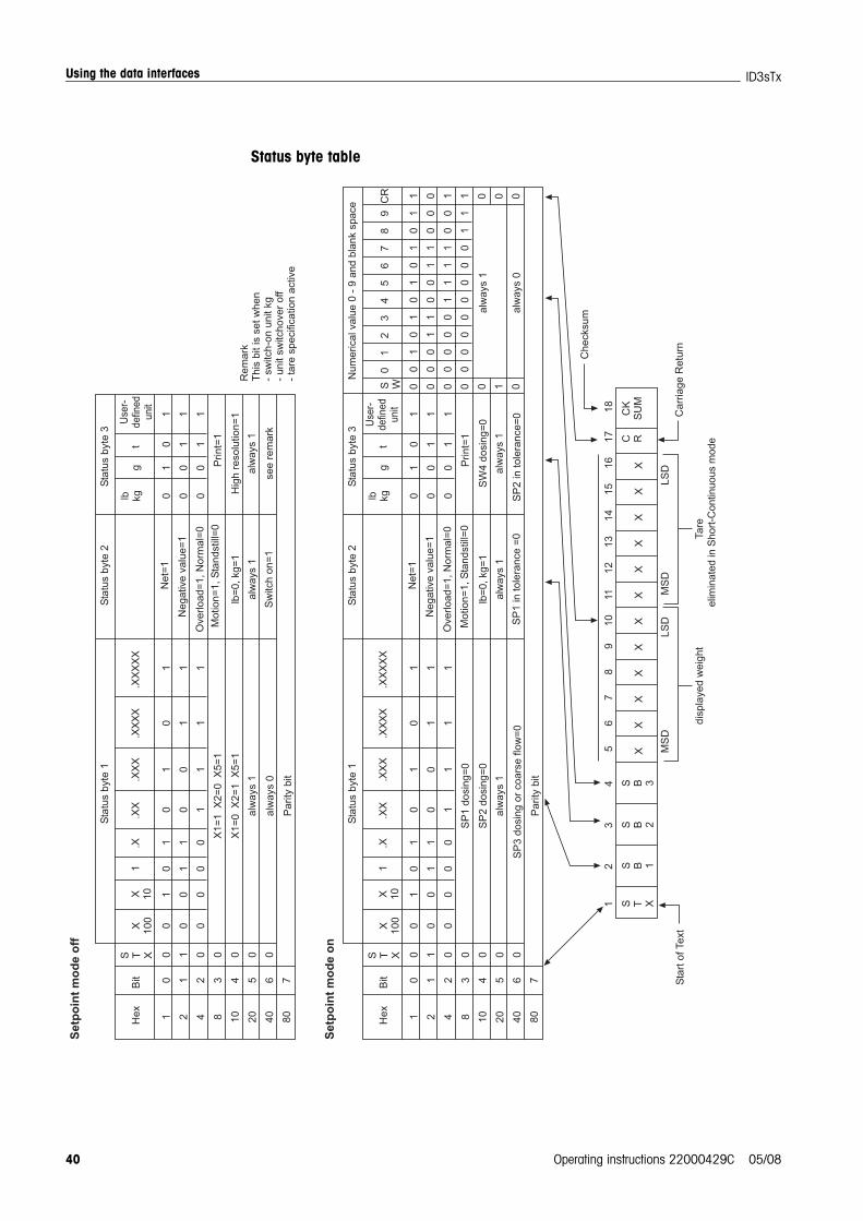
Status byte table
!
! "
#
#
$#
%&
'!
% (
)%
%*
'
*&
'+"
,-
%*
+""
.
/
& 0*
&*
*
"
-
%
%*
(
+
&%
*"
&%
*"
&%
*"
% ,%
0%
!
! "
#
#
$#
%&
'!
% (
)%
%*
'
*&
'+"
*
%
*,
+""
.
/
& 0*
&*
*
1
&%
*"
*
%
*,
1
2
3
!(
,
#
/
*&
*+
4,
2 3
25
.
)
)
67
67
6)
6
&4
&
"-
%
0
2
" 3
*
2-
,+
(
(
*
&*
-%
/2
%**
%
(%&
3 (
+
-
- *
/
,-/
%*
*+
"/*
,-%
# %0
0/
4 ,
0,
%*
,#

Using the data interfaces
Operating instructions 22000429C 05/08 41
ID3sTx
6.2 Demand modeThis operating mode is suitable for the transfer of data to a printer.Transfer commences as soon as a print command is received, e.g. when the PRINTkey is pressed.Data is only transferred when the weighing system is at rest and when the grossweight is ≠ 0 in demand mode. Data records of up to 6 fields can be transferred in demand mode. Data record con-figuration and printout takes place in Setup mode.
Output formatData records are transferred in the following formats:
in a single line:
in several lines:
.
.
.
LegendSTX hex 02, ASCII character for "start of text"
is required for some printers, can be deactivated in Setup.DF1 ... 6 Weight field, data field with 8 characters for the weight value. The first char-
acter is blank for positive values and – for negative values. This is followed by 7 characters for the actual weight, 1 of which being thedecimal point. If the value is transferred without a decimal point, it is prefixed by a blank.The data field for broad printing is prefixed by the ASCII character SO(hex 0E) and the associated unit field is suffixed by the ASCII character SI(hex 0F).When printing in brackets, a measured weight is framed by:< >, unlike avalue entered by hand.
UF1 ... 6 Unit field, which can contain the following units:Gross weight: lb, kg, g, t; Net weight: lbN, kgN, gN, tN,Tare weight: lbT/lbPT, kgT/kgPT, gT/gPT, tT/tPT.Can be deactivated in Setup.
CR Carriage return (hex 0D)CHK Checksum (two's complement of the binary sum of the 7 lower bits of all
previously transmitted characters, including STX and CR).LF Line feed (hex 0A)
STX DF1 UF1 DF2 UF2 ... DF6 UF6 CR CHK LF
STX DF1 UF1 CR CHK LF
STX DF2 UF2 CR CHK LF
STX DF6 UF6 CR CHK LF

Using the data interfaces
42 Operating instructions 22000429C 05/08
ID3sTx
Other possible data fields (DF):Weighing system number:
Data field with 8 characters, 5 of which = SCALE, 1 space, 2 characters forthe weighing system number
Date and time:Data field with 17 characters, 8 of which in the selected date format, 1 space, 2 characters for the hours, 1 character for a colon, 2 charactersfor the minutes, 1 space, 2 characters to enter AM/PM
Characteristics memory:Data field with 14 characters, 6 of which are spaces, 1 character for #,1 space, 6 characters for the ID number of the characteristics memory
Empty field: Data field with 7 spaces
6.3 <ENQ> continuous modeA computer can call weight data from the weighing terminal in <ENQ> continuousmode.ASCII command <ENQ> (= hex 05) initiates the transfer of a continuous mode datarecord.
Output formatAs for continuous mode.
6.4 ASCII input modeSome weighing terminal functions can be controlled by an external computer in ASCIIinput mode as long as demand mode or one of the continuous modes has been pro-grammed for data output.
The interfaces recognize the following ASCII characters in upper-case letters:
• C = CLEAR key
• P = PRINT key
• T = TARE key
• Z = ZERO key
It is not necessary to define the command with CR (carriage return) and LF (linefeed).
NoteEach command needs approx. 2 update intervals in the terminal. While a commandis being processed, all other incoming commands are ignored.
Wait for two update intervals between two commands. (refer to section 5.5.2 for information concerning update intervals).
Using the data interfaces
Operating instructions 22000429C 05/08 43
ID3sTx
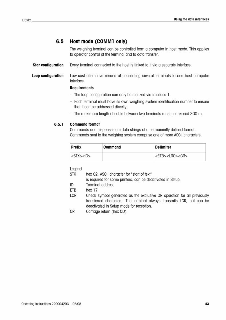
6.5 Host mode (COMM1 only)The weighing terminal can be controlled from a computer in host mode. This appliesto operator control of the terminal and to data transfer.
Star configuration Every terminal connected to the host is linked to it via a separate interface.
Loop configuration Low-cost alternative means of connecting several terminals to one host computerinterface.
Requirements
– The loop configuration can only be realized via interface 1.
– Each terminal must have its own weighing system identification number to ensurethat it can be addressed directly.
– The maximum length of cable between two terminals must not exceed 300 m.
6.5.1 Command formatCommands and responses are data strings of a permanently defined format.Commands sent to the weighing system comprise one of more ASCII characters.
LegendSTX hex 02, ASCII character for "start of text"
is required for some printers, can be deactivated in Setup.ID Terminal addressETB hex 17LCR Check symbol generated as the exclusive OR operation for all previously
transferred characters. The terminal always transmits LCR, but can bedeactivated in Setup mode for reception.
CR Carriage return (hex 0D)
Prefix Command Delimiter
<STX><ID> <ETB><LRC><CR>

Using the data interfaces
44 Operating instructions 22000429C 05/08
ID3sTx
6.5.2 Response formatThe commands received by the weighing system via the data interface are acknowl-edged by the weighing system in a response data record.
LegendACK Command executedNAK Error message indicating correct ID, but incorrect LCR, command or com-
mand parameterRefer to Section 6.5.1 for STX, ID, ETB, LCR, CR.
The following description does not refer to the prefixes, delimiters or the acknow-ledgment part of the response in detail. It merely refers to the commands and, whereapplicable, the responses.
6.5.3 Commands and responses
Overview<D> Interrogating and entering the date<F> Interrogating and entering the time<T> Taring<K> Specifying the tare weight<Z> Zeroing<P> Printing<S> Interrogating and entering setpoint values<M> Unit switchover<W> Interrogating weight values<L> Locking the keypad<I> Interrogating the weighing system identification number<B> Storing unit, tare weight, zero value and weighing system identification<C> Interrogating Setup status<Q> Interrogating status values
Interrogating the date
Entering the date
Prefix Acknowledgment Response Delimiter
<STX><ID> <ACK> or<NAK>
Not mandatory <ETB><LRC><CR>
Command <D>
Response <Date> Date: ASCII characters, format as programmed in Setup
Command <D><Date><1> Date: ASCII characters, format as programmed in Setup

Using the data interfaces
Operating instructions 22000429C 05/08 45
ID3sTx
Interrogating the time
Entering the time
Taring
Specifying the tare weight
Zeroing
Printing
Interrogating setpoint values
Command <F>
Response <Time> Time: ASCII characters, format HHMMX, HH = 00 ... 12, MM = 00 ... 59, X = 1 = PM, X = 2 = AM
Command <F><Time><1> Time: ASCII characters, format HHMMX, HH = 00 ... 12, MM = 00 ... 59, X = 1 = PM, X = 2 = AM
Command <T>
Command <K><Tare weight> Tare weight: 8 ASCII characters incl. decimal point, enter the tare weight with leading zeros, where applicable. The weighing terminal adjusts the position of the decimal point and rounds up or down automatically.
Command <Z>
Command <P>
Command <S><#><,> #: Setpoint number
Response <Setpoint> Setpoint value: 8 ASCII characters incl. decimal point, with leading zeros, where applicable.

Using the data interfaces
46 Operating instructions 22000429C 05/08
ID3sTx
Entering setpoint values
Unit switchover
Interrogating weight values
Locking the keypad
Command <S><#><,><Setpoint>#: Setpoint number:0 = Setpoint 11 = Setpoint 22 = Setpoint 33 = Setpoint 44 = Setpoint 1 (after-flow compensation)/(coarse/fine changeover)5 = Setpoint 2 (after-flow compensation)/(coarse/fine changeover)6 = Setpoint 3 or Setpoint 1 (after-flow compensation)7 = Setpoint 4 or Setpoint 2(after-flow compensation)8 = Tolerance 1 zero/Setpoint 19 = Tolerance 2 zero/Setpoint 2
Setpoint:8 ASCII characters incl. decimal point, enter leading zeros, where applicable, the position of the deci-mal point is adjusted by the weigh-ing terminalThe rounding up or down of the set-point value must be in accordance with the rounding up or down pro-grammed in the terminal.
Command <M><0><M><1>
Switch over to lbSwitch over to kg/user-defined unit
Command <W><0><W><1><W><2><W><3>
Net weightGross weightTare weightDisplayed weight
Response <Type><Unit><Weight value>
Type:G = GrossT = TareN = NetO = OverloadH = Tare presetU = Underload
Unit:L = poundsK = kilogramsA = user-defined unit G = gramsT = ton
Weight value:8 characters, with decimal point, leading zeros dis-played as spaces
Command <L><0><L><1>
Release the keypadLock the keypad
Using the data interfaces
Operating instructions 22000429C 05/08 47
ID3sTx
Interrogating the ID number in the characteristics memory
Entering an ID number into the characteristics memory
Storing unit, tare weight, zero value and ID number
Interrogating Setup status
Command <I>
Response <ID number> ID number: 6 ASCII characters between 0 and 9 and 20h (space)
Command <I><ID number> ID number: 6 ASCII characters between 0 and 9 and 20h (space)
Command <B>
Command <C><##> ##: 2 ASCII characters = number of the Setup parameter
Response <Status value> Status value: 8 ASCII characters = current parameter value

Using the data interfaces
48 Operating instructions 22000429C 05/08
ID3sTx
Interrogating status values
Command <Q>
Response <S1><S2><S3><S4><S5><S6> S1...S6 = Status bytes
Meanings of the status bytesThe only bits given here are those which provide information about a status. The others are always set to state 0. Bit 7 is always the parity bit.
Status byte 1Bit 2 1 0 = Position of the
decimal point0 0 0 = xxxx000 0 1 = xxxxx00 1 0 = xxxxxx0 1 1 = xxxxx.x1 0 0 = xxxx.xx1 0 1 = xxx.xxx1 1 0 = xx.xxxx
Bit 4 3 = Rounding0 1 = 11 0 = 21 1 = 5
Bit 6 1 = Print demand
Status byte 2Bit 0 1 = Net
0 = GrossBit 1 1 = Pounds
0 = KilogramsBit 2 1 = User-defined unit activeBit 6 1 = Tare enabled
0 = Tare disabled
Status byte 3Bit 2 1 = Weighing system
not at rest Bit 3 1 = Zero indication for
gross/netBit 5 1 = OverloadBit 6 1 = Unit switchover
active
Status byte 4Bit 0 1 = Negative weightBit 2 1 = Manual taring Bit 5 1 = Keypad lockedBit 6 1 = Higher resolution on
Status byte 5 (Starting state)Bit 3 1 = ON state
0 = Normal stateBit 4 1 = Setpoint mode on
Status byte 6Bit 0 0 = Setpoint 1,
Fine flow on Bit 1 0 = Setpoint 2,
Fine flow onBit 2 0 = Setpoint 3/Setpoint 1,
Coarse flow onBit 3 0 = Setpoint 4/Setpoint 2,
Coarse flow onBit 4 0 = Setpoint 1/
Zero tolerance 1 Fine flow on
Bit 5 0 = Setpoint 1/Zero tolerance 1Fine flow on

Using the data interfaces
Operating instructions 22000429C 05/08 49
ID3sTx
6.6 SICS level 0 input/output commands (COMM1 only)SICS level 0 commands enable operation of networked METTLER TOLEDO weighingterminals using the same application software.
6.6.1 Command formatCommands and responses are data strings of a permanently defined format.
Commands that are sent to the weighing system comprise one or several ASCII char-acters. The following rules must be observed:
• All commands must be entered in upper-case letters.
• The individual parameters in a command must be separated from one another,and from the command name itself, by a "_" (ASCII 32 dec.).
• Conclude each command string with "CR LF" (ASCII 13 dec., 10 dec.).The characters "CR LF" are usually entered by pressing the Enter/Return key andare therefore not given explicitly in the table of commands.
• A command string must not contain more than 24 characters, including "CR LF".
Command format
6.6.2 Response formatThe weighing system acknowledges every command received via the data interfacewith a response. Formats are distinguished by the following criteria:
• Responses with weight values
• Responses without weight values
Example of the response format with weight value
Command Delimiter
1 – 3 characters CR LF
Identification – Status – Weight value – Unit Delimiter
1 ... 2 characters for specification of the com-mand
1 character 10 charac-ters, incl. sign
1 ... 3 characters
CR LF

Using the data interfaces
50 Operating instructions 22000429C 05/08
ID3sTx
6.6.3 Error messagesAll error messages comprise 2 characters and the string delimiter CR LF.Possible error messages:
• ES Syntax errorThe weighing system has not recognized the received command.
• ET Transmission errorThe weighing system has received a "garbled" command.
• EL Logical errorThe weighing system cannot execute the command.
6.6.4 Commands
OverviewI1 Identification string 1, interrogate the type of command setI2 Identification string 2, interrogate the weighing system identificationS Transmit the weight value at restSI Transmit the weight value immediatelySIR Transmit the weight value immediately and repeatT TareZ Zero@ Reset
Tips for the programmer
Command and response You can improve the reliability of your application software by evaluating the weigh-ing system's response to a command issued by your program. The responseacknowledges the fact that the weighing system has received the command.
Reset When establishing a communication link between the weighing system and the sys-tem, you should always send a reset command to the weighing system to ensurethat it has assumed a defined state. Erroneous characters may be received or trans-mitted when the weighing system or system is switched on or off.
I1 – Interrogating the type of command set
Command I1 Transmit the code for the implemented command set
Response I1_A_0_2.10 = SICS level 0, Version 2.10 (command set S, SI, SIR, T, Z, I1, I2, @)
I1_I Unable to execute command

Using the data interfaces
Operating instructions 22000429C 05/08 51
ID3sTx
I2 – Interrogating the weighing system identification
S – Transmit the weight value at rest (Send)SI – Transmit the weight value immediately (Send Immediately)SIR – Transmit the weight value immediately and repeat (SI and Repeat)
Command I2 Transmit weighing system identification
Response I2_A_text Identification
I1_I Unable to execute command
Remark • The length of the "text" character string is determined by the type of weighing system
Example Command: I2Response: I2_A_"ID3sTx_1500.0_kg"
Command S Send the current net weight value at rest
SI Send the current net weight value irrespective of whether the weighing system is at rest or not
SIR Send the current net weight value repeatedly irrespective of whether the weighing system is at rest or not
Response S_S_weightvalue_unit
Current weight value at rest in the first unit
S_D_weightvalue_unit
(Dynamic) weight value not at rest in the first unit(Commands SI and SIR only)
S_I Unable to execute command, weighing system currently exe-cuting another command (e.g. taring or timeout, not at rest)
S_– Weighing system in the underload range
S_+ Weighing system in the overload range
Remarks • The duration of the timeout is determined by the type of weighing system.
• The first unit is the weight unit displayed at switch-on.
• The last weight value (static or dynamic) prior to receiving the SI command issent.
• SIR is overwritten (canceled ) by the S, SI and @ commands.
Example Command: SIRResponse: S_D_ _ _ _ _12.07_kg; S_D_ _ _ _ _12.08_kg;
S_S_ _ _ _ _12.08_kgThe weighing system transmits dynamic (status D) or stationary (status S) weight values repeatedly.

Using the data interfaces
52 Operating instructions 22000429C 05/08
ID3sTx
T – Taring (Tare)
Command T Taring, i.e. storing the next weight value recorded at rest as the new tare value.
Response T_S_weightvalue_unit
Taring executed, i.e. stationary criterion and taring range observed. The new tare value corresponds to the change in the weight acting on the weighing system since the last zeroing operation.
T_I Unable to execute tare command as the weighing system is currently executing another command (e.g. zeroing or time-out, not at rest)
T_+ Upper-limit violation of the taring range
T_– Lower-limit violation of the taring range
Remarks • The value in the tare memory is overwritten by the next value.
• The duration of the timeout is determined by the type of weighing system.
• The first unit is the weight unit displayed at switch-on.
Example Command: TResponse: T_S_100.00_kg
The weighing system has been tared, the value 100.00 kg has been stored in the tare memory.

Using the data interfaces
Operating instructions 22000429C 05/08 53
ID3sTx
Z – Zeroing (Zero)
@ – Reset
Command Z Zeroing the weighing system
Response Z_A Zeroing executed, i.e. stationary criterion and zeroing range observed. According to this: gross = net = tare = 0.
Z_I Unable to execute the zeroing command as the weighing system is currently executing another command, e.g. taring or timeout and is therefore not at rest.
Z_+ Upper-limit violation of the zeroing range
Z_– Lower-limit violation of the zeroing range
Remarks • The tare memory is erased during a zeroing operation.
• The zero point, which is determined at switch-on, is not influenced by this command, i.e. the measuring ranges remain unaffected.
• The duration of the timeout is determined by the type of weighing system.
Example Command: ZResponse: Z_A Zeroing executed.
Command @ Returns the weighing system to its state at switch-on without zeroing.
Response I4_A_"text"
Weighing system identification, the weighing system is ready for ser-vice.
Remarks • The reset command is always executed.
• All parameters that have been changed via the interface are reset.
• Unanswered commands are erased.
• The tare memory is reset to zero.
• If the weighing terminal is on standby, this command switches it on.
• If a reset command is received during the calibration and test phase, it will not be executed until the phase has terminated.
Example Command: @Response: I4_A_"0123456789"
The weighing system has been reset and transmits its weighing sys-tem identification.

Using the data interfaces
54 Operating instructions 22000429C 05/08
ID3sTx
6.7 Configuration of the interfaces on the Fiber Optic ConverterEach of the two channels of the Dual Channel Fiber Optic Converter can be used as a20 mA CL interface or a RS232 interface. Jumpers must be set on the Dual ChannelFiber Optic Converter PCB in order to configure the interfaces.
Undo the four Phillips screws in the Dual Channel Fiber Optic Converter enclosureand remove the cover.
Jumper positions for the two channels on the converter PCB
Set the jumper for channel 1 or channel 2 as shown in the diagram.
Replace the cover and secure to the converter enclosure with the 4 screws. The4 fixing straps can be fitted permanently, if required.
JU1
JU2
JU7
JU9
JU8
JU10
JU3
JU4
JU5
JU6
Channel 1
Channel 2
32
1
65
4
32
1
1234
65
4
32
1
65
4
32
1
32
1
65
4
32
1
1234
5
4
32
1
6
65
4
32
1
!
"#
$!
%&
%
!
&
%
!
!%
&
%
!
&
%
!
!
"#
$!
%
!
&
%
!
!%
&
%
!
&
%
!
%&
What to do if ...
Operating instructions 22000429C 05/08 55
ID3sTx
7 What to do if ...
EXPLOSION HAZARD
Always comply with the instructions for safety in Chapter 1 when working withthe ID3sTx weighing terminal.
7.1 Error messages
Error message Cause Remedy
E1 … E4 Internal error Call METTLER TOLEDO Service.
E10 Setpoint mode activated in Setup but no setpoint values entered
Press the CLEAR key and enter set-point values or deactivate setpoint mode in Setup.
E11 Power supply interrupted while sleep mode activated, e.g. OFF key pressed; zero point, tare value and weighing plat-form number lost
Press the CLEAR key and reenter values or deactivate sleep mode in Setup.
E16 Calibration values incorrectError message E24 erased and calibra-tion started
1. Press the CLEAR key and go to Setup.
2. Enter correct values in parameter 04.
Conversion factor ≠ 0 selected in parameter 93
1. Press the CLEAR key and go to Setup.
2. Set the conversion factor = 0 in parameter 93.
E21 (in Setup) Maximum load incorrect Press the CLEAR key and enter the permitted maximum load.
E26 (in Setup) Maximum number of 25000 points exceeded
Press the CLEAR key and enter ≤ 25000 points.
E27 (in Setup) Overload value entered incorrectly Enter overload value ≥ maximum load.
E32 Calibrating weight too light Press the CLEAR key and apply additional calibrating weight.
Wrong signal from the weighing plat-form
1. Check the weighing platform for mechanical faults.
2. Check the maximum load in Setup.
3. Call METTLER TOLEDO Service.

What to do if ...
56 Operating instructions 22000429C 05/08
ID3sTx
7.2 Other errors
E34 Calibrating weight too heavy Press the CLEAR key and reduce the calibrating weight to < 105 % of the maximum load.
E35 (in Setup) Calibrating weight entered incorrectly 1. Press the CLEAR key.
2. Recalibrate the weighing platform; the entered calibrating weight must be a multiple of the specified point size.
SP Err Setpoint value incorrect Enter an acceptable setpoint value.
EEE Upper-limit violation of the tolerance for automatic zeroing when switching on and/or tare interlock activated
1. Remove the load from the weighing platform and reset to zero.
2. Recalibrate the weighing platform.
-EEE Lower-limit violation of the tolerance for automatic zeroing when switching on, e.g. because load plate missing, and/or tare interlock activated
1. Increase weight to 0, e.g. apply load plate.
2. Recalibrate the weighing platform.
3. Increase the tolerance range for automatic zeroing when switching on (parameter 14).
Error message Cause Remedy
Error Cause Remedy
Terminal does not switch on
Terminal switched off or sleep mode active
Switch terminal on.
Internal or external battery flat or defec-tive
Connect up to another battery and recharge the flat battery.
Connected equipment defective Check or replace connected equip-ment.
Internal error Call METTLER TOLEDO Service.
Basic functions do not respond
Contradictory settings in Setup Select Setup parameter 99 = 2 and confirm restoration of the factory set-tings.
What to do if ...
Operating instructions 22000429C 05/08 57
ID3sTx
Displayed information incorrect
Weighing platform not zeroed correctly Remove the load, reset to zero and repeat the weighing operation.
Tare value incorrect Erase tare value and/or enter the cor-rect tare value.
Load plate / weighed article making contact with surrounding surface
Adjust until there is no contact.
Weighing platform on a slant Level the weighing platform.
Displayed information unstable
Disturbances at the installation location Adjust vibration adapter.
Draft Eliminate draft.
Load plate / weighed article making contact with surrounding surface
Adjust until there is no contact.
Fault in the power supply Call METTLER TOLEDO Service.
Display blocked Internal error Call METTLER TOLEDO Service.
Displayed information changes suddenly
Weighing platform cable moved or "dragging"
Reroute the weighing platform cable so that it is protected and reduce the possibility of movement to a mini-mum.
Display slow to respond Weighing platform failure Check weighing platform.
Keypad input impossible Keypad defective Call METTLER TOLEDO Service.
Weighing terminal does not work properly
Poor electrical contact Call METTLER TOLEDO Service.
Terminal fails to cali-brate
Initial load >2/3 cell capacity Reduce the initial load to less than 2/3 of the cell capacity.
Wrong date/time Power supply from internal battery inter-rupted for longer than 30 s
Set the date and time in Setup.
Error Cause Remedy

Cleaning and charging the battery
58 Operating instructions 22000429C 05/08
ID3sTx
8 Cleaning and charging the battery
8.1 Safety instructions
EXPLOSION HAZARD
Always comply with the safety instructions in Chapter 1 when working with theID3sTx weighing terminal.
8.2 Cleaning
RISK OF DAMAGING THE SURFACE
Make sure that the enclosure cover and battery compartment cover are closedproperly as the requirements of IP65 are not fulfilled if this is not the case.
Never use aggressive cleaning agents.
Never spray the cleaner directly onto the terminal.
Use a clean, soft cloth and mild cleaning agent to wipe the keypad and theenclosure.
8.3 Charging the battery
EXPLOSION HAZARD
Always charge the batteries in the safe zone.
Only use METTLER TOLEDO battery chargers and only use these to chargeMETTLER TOLEDO battery packs.
Only install and use METTLER TOLEDO battery chargers in the safe zone.
Notes
• Never fully discharge the battery unit (lead rechargeable)! No "memory" effect.
• When the battery symbol appears on the display, charge the battery as soon aspossible. The battery then has sufficient capacity to run for approx. 8-10 h.
• When used continuously, a second battery pack should be available, so that thiscan be used while the original battery pack is being charged. Leave the other bat-tery unit on the charger until used (float charging)!
• In the event of longer pauses (over several days), remove the battery unit andcharge it until it is reused.
• Replace the battery pack after it has been recharged approx. 250 times.
• The battery compartment is located on the right-hand side of the ID3sTx enclosure.
Disposal
Dispose of used batteries properly!

Cleaning and charging the battery
Operating instructions 22000429C 05/08 59
ID3sTx
8.3.1 Charging the internal battery
1. If sleep mode has been activated, switch the weighing terminal off with the FUNC-TION and 9 keys or, if this is not the case, with the OFF key.
2. Use a screwdriver to undo the two screws and remove the cover from the batterycompartment.
3. Remove the battery pack.
4. Insert another fully charged battery pack within 30 seconds to ensure that thedate and time information is retained.
5. Replace the cover on the battery compartment and tighten the two screws.
6. Move the original battery pack to the safe zone and recharge with the METTLERTOLEDO charger.
7. Follow the operating instructions for the charger.
8.3.2 Charging the external battery
EXPLOSION HAZARD
Restore equipotential bonding after charging the external battery.
1. If sleep mode has been activated, switch the weighing terminal off with the FUNC-TION and 9 keys or, of this is not the case, with the OFF key.
2. Release the bayonet lock on the battery.
3. Connect up another fully charged battery pack within 30 seconds to ensure thatthe date and time information is retained.
4. Plug the connector on the end of the battery cable into the socket in the batterypack. Press the two together carefully, turning at the same time, until the bayonetlock latches into place.
5. Turn the retainer on the cable clockwise to secure the joint.
6. Move the discharged battery pack to the safe zone and recharge with theMETTLER TOLEDO charger.
7. Follow the operating instructions for the charger.
Technical data
60 Operating instructions 22000429C 05/08
ID3sTx
9 Technical data
9.1 General data
Enclosure Stainless steel enclosureType of protection: II 2 G EEx ib IIC T4
II 2 D IP65 T 50 °CIP degree of protection: IP65
Display High-resolution LCD with 7-segment display, 6 digitsCharacters 25 mm highWeight displayed in kg, lb, g, tOptional decimal point or commaSymbols for Charge battery, Gross weight (G), Tare weight (T or PT), Net weight(Net) and Zero (Z)
Keypad Tactile feedback membrane keypad, 4 x 5 keys
Operating temperature –10 °C ... +40 °C, relative humidity: 10 % ... 95 %
Storage temperature –18 °C ... +60 °C, relative humidity: 10 % ... 95 %
Weight With internal battery approx. 3.2 kgFor connection to the external battery approx. 3.1 kg With internal power supply unit approx. 4.5 kg
Dimensions Terminal
External battery
254 mm
165 mm
191 mm
101.6 mm
178 mm
217.9 mm
M4 M4
21.4 mm
!""%
!
!%% %
!!& &
& &
$ &
!
! &
"&
$
! &'

Technical data
Operating instructions 22000429C 05/08 61
ID3sTx
Dual Channel Fiber Optic Converter
9.2 Electrical data
ID3sTx Ui = 14.3 V; Ii = 935 mA; Pi = 3.3 W
Internal battery U0 = 13.6 V; I0 = 890 mA; P0 = 2.9 W1.2 AH; intrinsically safeAluminium enclosure; weight approx. 0.97 kgOperating time approx. 25 – 55 h, determined by the update rate and the number ofweighing cells and interfaces connectedCharging time approx. 32 hMax. temperature while charging 30 °C, ideally less than 10 °CRecommended storage temperature: +5 °C – +25 °C
Type of protection: II 2 G EEx ib IIC T4
External battery U0 = 13.6 V; I0 = 895 mA; P0 = 3.0 W7 AH; intrinsically safeStainless steel enclosure; weight approx. 4.3 kg; connected to the ID3sTx weighingterminal via a non-detachable cableOperating time approx. 200 – 350 h, determined by the update rate and the numberof weighing cells and interfaces connectedCharging time approx. 12 hMax. temperature while charging 30 °C, ideally less than 10 °CRecommended storage temperature: +5 °C – +25 °C
Type of protection: II 2 G EEx ib IIC T4II 2 D IP65 T 120 °C
Internal power supplyunit
U0 = 12.65 V; I0 = 888 mA; P0 = 2.8 WInput voltage: 230 V AC, output voltage: 11.8 – 14.0 V DCTypical short-circuit current: 213 mA
Type of protection: II 2 G EEx m e [ib] IIC T4
!%
!
%%
"
!!!&!

Technical data
62 Operating instructions 22000429C 05/08
ID3sTx
9.3 Functions
Print When the key is pressed as long as the data interface is installed
Unit switchover Switch between kg and lb or a user-defined unit by pressing the key
Zeroing Automatic (at ±2 % or ±10 % of the weighing system's capacity) or manual (at ±2 % or ±20 % of the weighing system's capacity)
Tare compensation By pressing the key or automatic
Tare recall By pressing the key
Sleep mode Switch-off time adjustable from 1 to 99 minutes
Power management Automatic switch-off when the voltage drops below 11.1 V DC
Setpoints 4 setpoints with tolerances for 4 filling operations at one speed or 2 setpoints and tolerances for 2 filling operations with coarse and fine flow
Date/time Date in European or US format, time in 24-hour format
Weighing systemidentification
6-digit
Update rate Adjustable between 7 and 16 measurements per second
Standstill check Adjustable in 5 stages
Display update Adjustable between 0.25 and 2.4 seconds
9.4 Compatible weighing platforms
METTLER TOLEDOweighing platforms
D..Tx, PTA459x, PUA579x, PBA430x, RWM1x
Weighing cells fromother manufacturers
Up to 4 weighing cells with 2mV/V, cell resistance 350 ΩWeighing cells with 3 mV/V if the weighing range + preload < 2/3 nominal load of the bending rodUse at least 39 % of the cell capacity for spanConnect weighing cells via the junction box

Accessories
Operating instructions 22000429C 05/08 63
ID3sTx
10 Accessories
10.1 Mechanical accessories
Order No.
Wall mounting To secure the ID3sTx weighing terminalto the wall, incl. fixing material, stainless steel throughout
00 504 130
Floor stand For a free-standing installation of the ID3sTx weighingterminal, incl. fixing material to bolt the tripod to thefloor, stainless steel throughout
00 504 132
Base For mobile installation of the floor stand, stainless steelthroughout
00 503 701
Trestle stand To secure the ID3sTx weighing terminalto the trestle for KB or KC weighing platforms, stainless steel throughout
00 504 128
Scale stand To secure the ID3sTx weighing terminal to DB30sTx/DB60sTx, stainless steel throughout
00 504 439
To secure the ID3sTx weighing terminal to PBA430x weighing platforms
• Dimensions 240 x 300 mm and 300 x 400 mmStand height 330 mm from load plate 21 254 243
• Dimensions 400 x 500 mm and 500 x 650 mmStand height 600 – 800 mm from load plate 21 254 244
Retainer To secure the ID3sTx weighing terminal to the shaft of aPTA459x weighing platform, complete
00 505 638
Battery holder To secure the external battery to the shaft of a PTA459xweighing platform
00 505 640
To secure the external battery to a trestle orfloor stand
22 000 150

Accessories
64 Operating instructions 22000429C 05/08
ID3sTx
10.2 Power supply
10.3 Data interfaces
Order No.
Internal battery pack 12 V DC / 1.2 AH, rechargeable, intrinsically safe, Ex approval for zone 1
22 000 144
Battery charger for theinternal battery pack
12 V DC / 1.2 AH, mains lead/plug with earthing contact(Europe)
22 000 145
12 V DC / 1.2 AH, mains lead/plug GB 22 000 146
External battery pack 12 V DC / 7 AH, rechargeable, intrinsically safe, Ex approval for zones 1 and 21
22 000 147
Battery charger for theexternal battery pack
12 V DC / 7 AH, mains lead/plug with earthing contact(Europe)
22 000 148
12 V DC / 7 AH, mains lead/plug GB 22 000 149
Power Supply 24 VDC Power supply unit for zone 1, without power cable 22 000 164
Power Supply 110 VAC Power supply unit for zone 1, without power cable 22 000 163
Order No.
Fiber-optic data I/O PCB For installation in the ID3sTx, to connect peripheral equip-ment via the Dual Channel Fiber Optic Converter
22 000 175
Dual Channel Fiber OpticConverter
2 serial interfaces, programmable as RS232 or CL 20 mA
Dual Channel Fiber Optic Converter for Europe 22 000 143
Dual Channel Fiber Optic Converter for GB 22 000 142
Input Board For installation in ID3sTx, for connection of passive powerelectronic equipment, e.g. tilt switch
22 002 364
METTLER TOLEDOFiber-optic cable
2 cables (transmit and receive), length between 1 m and300 m, specify desired length when orderingAlso order: End ferrules, see below
22 000 251
End ferrules For fiber-optic cable 22 000 138

Appendix
Operating instructions 22000429C 05/08 65
ID3sTx
11 Appendix
11.1 Table of Geo values
Country Geo value Country Geo value
A Austria 19 MA Morocco 13
AUS Australia 12 MAL Malaysia 5
B Belgium 21 MEX Mexico 5
BR Brazil 8 N Norway 24
CDN Canada 18 NL Netherlands 21
CH Switzerland 18 NZ New Zealand 16
CO Columbia 2 P Portugal 15
D Germany 20 PE Peru 6
DK Denmark 23 PRC China 10
E Spain 15 RA Argentina 13
EC Ecuador 1 RCH Chile 12
ET Egypt 11 RI Indonesia 6
F France 19 ROC Taiwan 10
GB Great Britain 21 ROK South Korea 15
GR Greece 15 S Sweden 24
HK Hong Kong 9 SA Saudi Arabia 8
I Italy 17 SF Finland 24
IL Israel 12 SGP Singapore 5
IND India 8 T Thailand 6
IR Iran 12 TA Turkey 16
IRL Ireland 22 USA United States 16
IS Iceland 26 YUG Yugoslavia 18
J Japan 14 YV Venezuela 5
JOR Jordan 11 ZA South Africa 12
KWT Kuwait 11

*22000429C* 22000429C
Subject to technical changes © Mettler-Toledo (Albstadt) GmbH 05/08 Printed in Germany 22000429C
Mettler-Toledo (Albstadt) GmbHD-72458 AlbstadtTel. ++49-7431-14 0, Fax ++49-7431-14 232
www.mt.com/support